SPECIFICATION I ICAT. Commercial 30 Ton. Water Source/Geothermal Heat Pump
|
|
|
- Sydney Lamb
- 5 years ago
- Views:
Transcription


1 SPEIFIATION I IAT ION ATA O ommercial 30 Ton Water Source/eothermal Heat Pump
2
3 ENVISION SEIES 30 TON SPEIFIATION ATA Table of ontents Model Nomenclature AHI Data The Envision Series 30 Ton Inside the Envision Series 30 Ton ontrols Hot as eheat/hot as Bypass Application Notes Water Quality Installation Notes Dimensional Data Physical Data Electrical Data Blower Performance Data Antifreeze orrections eference alculations Legend and Notes Operating Limits orrection Factor Tables Pressure Drop Performance Data Wiring Schematics Engineering uide Specifications evision uide
4 ENVISION SEIES 30 TON SPEIFIATION ATA Model Nomenclature W A5 D V 360 * T A B A 0 1 F 1 A 2 SSS Brand W WaterFurnace 60Hz Model Type A5 ommercial Water-to-Air Large Packaged ompressor Type D Dual Single Stage Scroll abinet onfiguration V Vertical T Vertical Take-a-Part 1 Vertical with Factory Installed WSE 3 Vertical Take-a-Part with Factory Installed WSE Unit apacity (MBTUH) 360 Vintage * Factory Use Only Supply onfiguration T Top Upflow S Side Discharge eturn onfiguration ight Hand L Left Hand Voltage /60/ /60/ /60/3 Electrical Option A Non-Fused Disconnect, Phase uard Fused Disconnect, Phase uard Notes: 1 Not available with cabinet configuration 1 or 3 Non-Standard Options SSS None Drain Pan Option 2 Stainless Steel Filter Option A Standard, MEV4 B MEV13 Air oil Option 1 All-Aluminum, Uncoated 2 All-Aluminum, AlumiSeal Blower Option F VFD Motor/Standard Static Water ontrol Option 1 Standard, None 2 Motorized Isolation Valve 1 Water oil Option opper, Uninsulated D opper, Insulated N upronickel, Uninsulated P upronickel, Insulated efrigeration Option 0 Standard, None 6 Hot as Bypass 7 Hot as eheat 8 Hot as Bypass with Hot as eheat abinet Option A Standard, Painted Sound Kit Option B Standard, Sound Kit ontrol Option A Aurora Base ontrol E Aurora Base ontrol with Aurora UP DD F Aurora Base ontrol with Aurora UP DD with N ev.: 04 March 2015D 4

5 ENVISION SEIES 30 TON SPEIFIATION ATA AHI Data AHI/ASHAE/ISO English (IP) Units Water Loop Heat Pump round Water Heat Pump round Loop Heat Pump Model apacity Modulation Flow ate ooling EWT 86 F gpm cfm apacity Btuh EE Btuh/W Heating EWT 68 F apacity Btuh OP ooling EWT 59 F apacity Btuh EE Btuh/W Heating EWT 50 F apacity Btuh ooling EWT 77 F OP apacity Btuh EE Btuh/W Heating EWT 32 F apacity Btuh OP 360* Full Load , , , , , , Part Load , , , , , , ooling capacities based upon 80.6 F DB, 66.2 F WB entering air temperature Heating capacities based upon 68 F DB, 59 F WB entering air temperature All ratings based upon 208V operation. * atings are outside the scope of the AHI Water to Air/Brine to Air Heat Pumps ertification Program. 7/24/2015 All Envision Series 30 Ton product is safety listed under UL thru and performance tested in accordance with AHI/ISO standard
6 ENVISION SEIES 30 TON SPEIFIATION ATA AHI Data cont. The performance standard AHI/ASHAE/ISO became effective January 1, 2000 and replaces AHI Standards 320, 325, and 330. This new standard has three major categories: Water Loop (comparable to AI 320), round Water (AI 325), and round Loop (AI 330). Although these standards are similar there are some differences: Unit of Measure: The ooling OP The cooling efficiency is measured in EE (US version measured in Btu/h per Watt. The Metric version is measured in a cooling OP (Watt per Watt) similar to the traditional OP measurement. Water onditions Differences Entering water temperatures have changed to reflect the centigrade temperature scale. For instance the water loop heating test is performed with 68 F (20 ) water rounded down from the old 70 F (21.1 ). Air onditions Differences Entering air temperatures have also changed (rounded down) to reflect the centigrade temperature scale. For instance the cooling tests are performed with 80.6 F (27 ) dry bulb and 66.2 F (19 ) wet bulb entering air instead of the traditional 80 F (26.7 ) DB and 67 F (19.4 ) WB entering air temperatures. 80.6/66.2 data may be converted to 80/67 using the entering air correction table. This represents a significantly lower relative humidity than the old 80/67 of 50% and will result in lower latent capacities. Pump Power orrection alculation Within each model, only one water flow rate is specified for all three groups and pumping Watts are calculated using the following formula. This additional power is added onto the existing power consumption. Pump power correction = (gpm x ) x (Press Drop x 2990) / 300 Where gpm is waterflow in gpm and Press Drop is the pressure drop through the unit heat exchanger at rated water flow in feet of head. Blower Power orrection alculation Blower power is corrected to zero external static pressure using the following equation. The nominal airflow is rated at a specific external static pressure. This effectively reduces the power consumption of the unit and increases cooling capacity but decreases heating capacity. These Watts are significant enough in most cases to increase EE and OPs fairly dramatically over AI 320, 325, and 330 ratings. Blower Power orrection = (cfm x 0.472) x (esp x 249) / 300 Where cfm is airflow in cfm and esp is the external static pressure at rated airflow in inches of water gauge. ISO apacity and Efficiency alculations The following equations illustrate cooling calculations: ISO ooling apacity = ooling apacity (Btu/h) + (Blower Power orrection (Watts) x 3.412) ISO EE Efficiency (W/W) = ISO ooling apacity (Btu/h) x / [Power Input (Watts) - Blower Power orrection (Watts) + Pump Power orrection (Watt)] The following equations illustrate heating calculations: ISO Heating apacity = Heating apacity (Btu/h) - (Blower Power orrection (Watts) x 3.412) ISO OP Efficiency (W/W) = ISO Heating apacity (Btu/h) x / [Power Input (Watts) - Blower Power orrection (Watts) + Pump Power orrection (Watt)] omparison of Test onditions AI 320 ISO/AHI WLHP AI 325 ISO/AHI WHP AI 330 onversions: Airflow (lps) = cfm x 0.472; Water Flow (lps) = gpm x ; esp (Pascals) = esp (in wg) x 249; Press Drop (Pascals) = Press Drop (ft hd) x 2990 ISO/AHI LHP ooling Entering Air - DB/WB F 80/ / / / / /66.2 Entering Water - F / Fluid Flow ate * ** ** ** ** ** Heating Entering Air - DB/WB F Entering Water - F / Fluid Flow ate * ** ** ** ** ** Note *: Flow rate is set by 10 F rise in standard cooling test Note **: Flow rate is specified by the manufacturer Part load entering water conditions not shown. WLHP = Water Loop Heat Pump; WHP = round Water Heat Pump; LHP = round Loop Heat Pump 6
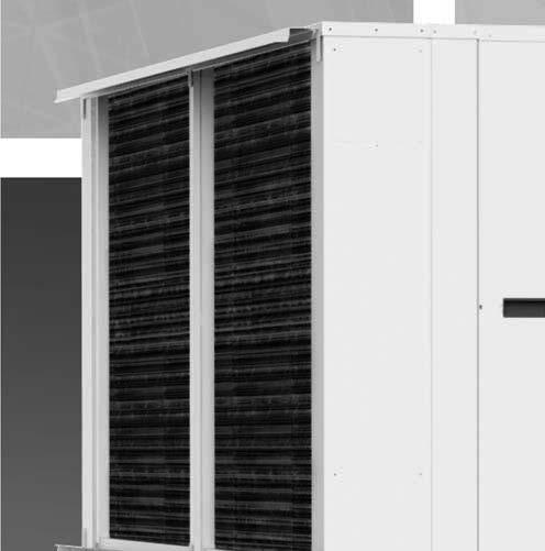
7 ENVISION SEIES 30 TON SPEIFIATION ATA The Envision Series 30 Ton WaterFurnace has expanded large water-to-air packaged heat pumps by introducing the Envision Series 30 Ton that comes with a host of new features. The Envision Series 30 Ton features a take-a-part design that allows the unit to simply be separated in the field for those jobs with not much room to maneuver. By splitting the air handling section from the compressor section, the design can be taken into a building in two different sections which makes it lower weight and smaller footprint. The sections can easily be rejoined. The unit features refrigerant quick disconnects that enable the unit to be factory charged and run tested yet allow separation in the field without touching a refrigerant gauge. Additional new features of the Envision Series 30 Ton is the variable frequency drive (VFD) with an LD display to adjust blower speeds eliminating manual pulley adjustments. Other advantages of Envision Series 30 Ton is the broad range of factory installed features such as hot gas reheat, internal 2-way water control valves, waterside economizer, electrical disconnects, and many others valuable features that make this product stand in a class of its own. Envision Series 30 Ton Highlights apacities ranging from 360,000 Btu/h output omplete commercial voltage selection of V/60 Hz/3ph, 460/60/3, and 575/60/3 Innovative features such as: Variable frequency drives provide a smooth start/stop operation & LD touchpad for speed change Optional take-a-part cabinet design featuring refrigerant quick disconnect fittings Optional factory installed waterside economizer reduces installation time and provides minimal piping Short ircuit urrent ating values of 100 ka Aurora DD controls 7

 utouts for wire routing Take-a-part cabinet offers flexible maneuvering and installation")
8 ENVISION SEIES 30 TON SPEIFIATION ATA The Envision Series 30 Ton cont. Product Features: Vertical abinet Variable frequency drives provide smooth start/stop operation and eliminates manual sheave adjustments Factory installed waterside economizer option Optional hot gas bypass & hot gas reheat valve Hinged control panel access with disconnect switch Aurora & UP DD controls platform Large coaxial heat exchanger High efficiency scroll compressors (x2) utouts for wire routing Take-a-part cabinet offers flexible maneuvering and installation efrigerant quick disconnects Fork pockets A true left and right return option is available. 8


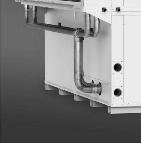
9 ENVISION SEIES 30 TON SPEIFIATION ATA The Envision Series 30 Ton cont. Product Features: Large aluminum rifled tube-in-fin heat exchanger Factory assembled Waterside Economizer piping Flush mount water connection Internal 3-way valve for Waterside Economizer option Optional fused electrical disconnect 24VA transformer ube fuses Aurora Base ontrol with optional Aurora Expansion Board ompressor contactor UP DD ontrol 9


10 ENVISION SEIES 30 TON SPEIFIATION ATA Inside the Envision Series 30 Ton ompressors Envision Series 30 Ton water-to-air units use high efficiency -410A, hermetically sealed; scroll compressors that are mounted on rubber grommets for vibration isolation. Scroll compressors provide high efficiency while providing greater tolerance to liquid refrigerant entering the suction port. Water-to-efrigerant Heat Exchanger Large oversized coaxial refrigerant to water heat exchangers provide unparalleled efficiency. The coaxes are designed for the low pressure drop and low flow rates. All coaxes are pressure rated at 450 psig water side and 600 psig on the refrigerant side. Optional refrigerant and coaxial heat exchanger insulation is available to prevent condensation in low temperature loop operation. All-Aluminum Air oil These air coils are constructed of lanced fin and rifled tube aluminum that is not susceptible to formicary corrosion. For additional condensate runoff and meeting project specifications, an optional AlumiSeal e-coating is available. Thermostatic Expansion Valve All units utilize balanced port, bidirectional, thermostatic expansion valves (TXV) for refrigerant metering. These valves have stainless steel capillary tube and bulb for improved robustness over conventional copper sensing capillary lines. The valve consists of a laser-welded power-head, forged brass valve body and diaphragm optimized for -410A applications. This valve design allows precise refrigerant flow in a wide range of entering water variation geothermal systems. 4-Way eversing Valve Units feature a reliable allbrass pilot operated refrigerant reversing valve. The reversing valve operation is limited to change of mode by the control to enhance reliability. Service onnections and Serviceability Two Schrader service ports are provided in every refrigerant circuit. The suction side and discharge side ports are for field charging and servicing access. All valves are 7/16 in. SAE connections. Vibration Absorbers Vibration absorbers are factory installed on every compressor suction and discharge tube to dampen the vibrations introduced by compressor on the refrigerant piping. These absorbers are constructed from corrugated copper tubing wrapped with stainless steel wire braid to provide strength and flexibility. abinet All units are constructed of corrosion resistant galvanized sheet metal with polyester powder coat paint rated for more than 1,000 hours of salt spray. Large lift-out access panels provide access to the compressor section from multiple sides. Air handler access panels allow servicing of the blower motor, blower, VFD, and drain pan. Side or top discharge option is available. Hot as Bypass/eheat The hot gas bypass option is designed to limit the minimum evaporating pressure in the cooling mode to prevent the air coil from icing. Hot gas reheat option provides consistent comfort by removing moisture from the air without over cooling the space. These options are available together or standalone. Internally Mounted Solenoid Valve Option When variable speed circulating pump systems are designed, low pressure drop (high v) solenoid valves are specified at each unit to vary the pump according to flow required. It is important that these valves be low pressure drop to avoid unwanted pump Watts. This option can be factory installed inside the unit. Water onnections Flush mount FPT water connection fittings allow one wrench leak-free connections and do not require a backup wrench. Blower Motor and Variable Frequency Drive Envision Series 30 Ton units are all equipped with a NEMA Premium motor equipped with a variable frequency drive. Variable frequency drives (VFD) provide smooth start/ stop operation to eliminate noise and vibration in the cabinet. VFDs also make service and installation easier by eliminating manual sheave adjustments. 10

 board, optional expansion board, control transformer, and optional UP DD control.")

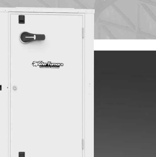
11 ENVISION SEIES 30 TON SPEIFIATION ATA Inside the Envision Series 30 Ton cont. ontrol Panel Envision Series 30 Ton control panel features a heavy-duty, hinged service door for ease of service and installation. The keyed service door features a factory mounted disconnect switch. The left interior of the control panel features high voltage components such as the electrical disconnect, fuses, and compressor contactors. The right interior of the panel features the Aurora Base ontrol (AB) board, optional expansion board, control transformer, and optional UP DD control. The control panel was designed with the technician in mind to provide convenient, clear wiring with plenty of working space. Electrical Disconnect A factory mounted, internally wired, disconnect is available to provide electrical isolation from high voltage supply at the heat pump. Separate circuit protection must be field installed in the power wiring and must comply with National Electric ode (NE) and/or local codes. Disconnect features include: Non-fused, rotary disconnect with on/off position Door interlocked, external pistol handle keeps door closed when disconnect is on Lockout/Tagout feature to keep the unit off during service omplies with NE Article Short ircuit urrent ating An optional factory mounted, fused disconnect provides the same benefits as the non-fused version yet increases the short circuit current rating, S to comply with buildings with a high available fault current. Adding the fused disconnect option ensures the equipment will comply with NE Article 409. Separate circuit protection must be field installed in the power wiring and must comply with National Electric ode (NE) and/or local codes. Disconnect features include: Increases S to 100 ka Door interlocked, external pistol handle keeps door closed when disconnect is on Lockout/Tagout feature to keep the unit off during service omplies with NE Article omplies with NE Article 409 for Short ircuit urrent ating Phase uard Factory mounted phase guard device is available to protect the compressor against loss of phase, reverse rotation, or phase imbalance. Fuses Envision Series 30 Ton units come with non-indicating UBEFuse which is a finger-safe, time-delay, power fuse with a small footprint, lass J rating, and have high fault interrupting rating. UBEFuse includes dual-element fuse construction that can withstand inrush current yet still allow low let-through currents during a fault condition. Drain Pan All units feature a stainless steel condensate pan that will not rust or corrode. All condensate connections are made with a 7/8 stainless steel drain tube stubbed from the unit. Units shall be externally trapped and vented according to local and national codes. Filter ail All units come standard with an open filter rail which can accommodate duct connections. For an optional deluxe filter rack, this can be done by special request. ontact a factory representative for availability. Filter options include both MEV 4, 2 in [5.1 cm] or an optional 2 in. [5.1 cm] MEV 13 for LEED certification points and high efficiency filtration. efrigerant Envision Series 30 Ton products all feature zero ozone depletion and low global warming potential refrigerant -410A. Air Handler Insulation Washable air handler insulation surface provides cleanability to further enhance IAQ. Factory Quality All refrigerant brazing is performed in a nitrogen environment. omputer controlled deep vacuum and refrigerant charging system. All joints are leak detected for maximum leak rate of less than 1/4 oz. per year. omputer bar code equipped assembly line ensures all components are correct. All units are computer run-tested with water to verify both function and performance. 11
12 ENVISION SEIES 30 TON SPEIFIATION ATA ontrols - Aurora Base ontrol Aurora Base ontrol The Aurora Base ontrol (AB) System is a complete residential and commercial comfort system that brings all aspects of the HVA system into one cohesive module network. Aurora uses the Modbus communication protocol to communicate between modules. Each module contains the logic to control all features that are connected to the module. The Aurora Base ontrol (AB) has two Modbus channels. The first channel is configured as a master for connecting to devices such as a communicating thermostat, expansion board, or other slave devices. The second channel is configured as a slave for connecting the Aurora Interface Diagnostic (AID) Tool. Aurora Unitary Protocol onverter (UP) The optional Aurora UP control provides unparalleled capability in several areas including energy, refrigerant, and performance monitoring, humidity, energy management, and service diagnostics, and then communicates it all thru standard DD protocols like N2, Lon and BAnet MS/TP. The most unique feature is integration of the Aurora Base ontrol and UP into the Envision Series 30 Ton as an integrated heat Pump and DD controller providing both a cost advantage and providing features not typically found on WSHP controls. This integration allows heat pump monitoring sensors, status and service diagnosis faults to be communicated thru the DD direct to the building automation system (BAS), giving building supervisors detailed and accurate information on every piece of equipment without removing an access panel! ontrol eneral Description Application Display/Interface Protocol Aurora Base ontrol The AB microprocessor provides all the features necessary to operate today s standard WSHPs that utilize dual capacity compressors and variable speed EM/5 speed EM blower motors with hot gas reheat. This control can communicate to a handheld diagnostic tool to help the installing contractor or service technician with equipment setup and service. By utilizing Modbus TU communication protocol, the AB board can communicate with additional devices on the Aurora network Used for residential and commercial applications that use single or dual capacity compressors with PS, 5-speed EM, or variable speed EM blower motors. This base control can also communicate to the AID Tool to display faults, inputs/outputs, and software revision. ommercial features such as hot gas reheat, slow opening water valve, and random start are also capable with the AB board. Optional AID toll can be used for field service. Standalone Aurora Base ontrol w/up BAnet or N2 The Aurora Unitary Protocol onverter (UP) is an integrated solution and communicates directly with the Aurora Heat Pump ontrols and allows access/control of a variety of internal Aurora heat pump operations such as sensors, relay operation, faults and other information. In turn, the UP then converts internal Aurora Modbus protocol to BAnet MS/TP, or N2 protocols and communicates to the BAS system. This provides the great benefit of complete control integration and a myriad of information available to the BAS from the heat pump control. Plus it also allows individual unit configuration such as EM fan speeds or freeze protection setting directly over the BAS without the need for access to the actual heat pump. The Aurora UP is implemented with the Aurora Base ontroller (AB) heat pump control into our latest water source heat pumps. All Internal Aurora points are accessible to the UP via firmware providing an integrated solution. All zone temperatures and zone sensors are connected to the UP on an Net bus, simplifying hook up at the unit. Net sensors can include a combination of zone temperature and humidity, O2, and VO sensors. The UP includes built-in support for a custom configurable keypad/display unit. Optional Equipment Touch display BAnet MS/ TP or N2 Open (DIP selectable) Aurora Base ontrol w/up LonWorks The Aurora Unitary Protocol onverter (UP) is an integrated solution and communicates directly with the Aurora Heat Pump ontrols and allows access/control of a variety of internal Aurora heat pump operations such as sensors, relay operation, faults and other information. In turn, the UP then converts internal Aurora Modbus protocol to NWorks protocol and communicates to the BAS system. The Aurora UP is implemented with the Aurora Base ontroller (AB) heat pump control into our latest water source heat pumps. All Internal Aurora points are accessible to the UP via firmware providing an integrated solution. All zone temperatures and zone sensors are connected to the UP on an Net bus, simplifying hook up at the unit. Net sensors can include a combination of zone temperature and humidity, O2, and VO sensors. The UP includes built-in support for a custom configurable keypad/display unit. Optional Equipment Touch display LonWorks AXB Expansion Board (Future Availability) Aurora Advanced ontrol adds the Aurora AXB expansion board and provides added I/O and standard features. AXB can be added to any of the above packages to enhance the I/O of the controls. efrigeration Monitoring provides Suction and discharge pressure, Suction, liquid line temps and superheat and subcooling. Performance Monitoring provides entering and leaving loop water temperatures, loop flow rate as well as heat of extraction or rejection rate into the loop. Energy Monitoring provides realtime power measurement (Watt) of compressor, fan, auxiliary heat and zone pump. Plus many more I/O options 12
 Test/onfiguration Button (See SW1 Operation Table) NOTE: efer to the Aurora Base ontrol Application and Troubleshooting uide")

13 ENVISION SEIES 30 TON SPEIFIATION ATA ontrols - Aurora Base ontrol cont. Aurora Base ontrol Field Selectable Options via Hardware DIP Switch (SW1) Test/onfiguration Button (See SW1 Operation Table) NOTE: efer to the Aurora Base ontrol Application and Troubleshooting uide and the Instruction uide: Aurora Interface and Diagnostics (AID) Tool for additional information. ontrol Features Software AB Standard Version 3.0 Single or Dual apacity ompressors Either single or dual capacity compressors can be operated. Variable Speed EM Blower Motor Option (If Applicable) A Variable Speed EM blower motor can be driven directly using the onboard PWM output. Four blower speeds are available based upon the, Y1, Y2, and W input signals to the board. The blower speeds can be changed either by the EM manual configurations mode method or by using the Aurora AID Tool directly. All four blower speeds can be set to the same speed if desired. 5-Speed EM Blower Motor Option (If Applicable) A 5-Speed EM blower motor will be driven directly using the thermostat connections. Any of the, Y1, or Y2/W signals can drive any of the 5 available pre-programmed blower speeds on the motor. All 5 Series "" vintage units will be wired this way at the factory. Other ontrol Features andom start at power up Anti-short cycle protection High and low pressure cutouts Loss of charge Water coil freeze detection Air coil freeze detection Over/under voltage protection ondensate overflow sensor Load shed Dehumidification (where applicable) Emergency shutdown Hot gas reheat operation (where applicable) Diagnostic LED Test mode push button switch Two auxiliary electric heat outputs Alarm output Accessory output with N.O. and N.. Modbus communication (master) Modbus communication (slave) 13 Test Mode The control is placed in the test mode by holding the push button switch SW1 for 2-5 seconds. In test mode most of the control timings will be shortened by a factor of sixteen (16). LED3 (green) will flash at 1 second on and 1 second off. Additionally, when entering test mode LED1 (red) will flash the last lockout one time. Test mode will automatically time out after 30 minutes. Test mode can be exited by pressing and holding the SW1 button for 2 to 5 seconds or by cycling the power. NOTE: Test mode will automatically be exited after 30 minutes. Variable Speed EM onfiguration Mode (If Applicable) The control is placed in the EM configuration mode by holding the pushbutton switch SW1 for 5 to 10 seconds, the high, low, and EM speeds can be selected by following the LED display lights. LED2 (yellow) will fast flash when entering the EM configuration. When setting speed LED3 (green) will be continuously lit, for low speed LED1 (red) will be continuously lit, and for high speed both LED3 (green) and LED1 (red) will be continuously lit. During the EM configuration mode LED2 (yellow) will flash each of the 12 possible blower speeds 3 times. When the desired speed is flashed press SW1, LED2 will fast flash until SW1 is released. speed has now been selected. Next select low speed, and high speed blower selections following the same process above. After third selection has been made, the control will exit the EM configuration mode. Aux fan speed will remain at default or current setting and requires the AID Tool for adjustment. eset onfiguration Mode The control is placed in reset configuration mode by holding the push button switch SW1 for 50 to 60 seconds. This will reset all configuration settings and the EEPOM back to the factory default settings. LED3 (green) will turn off when entering reset configuration mode. Once LED3 (green) turns off, release SW1 and the control will reset. DIP Switch (SW2) SW2-1 FP1 Selection Low water coil temperature limit setting for freeze detection. On = 30 F; Off = 15 F. SW2-2 FP2 Selection On = 30 F; Off = N/A SW2-3 V O/B - thermostat type. Heat pump thermostats with O output in cooling or B output in Heating can be selected. On = O; Off = B. SW2-4 Access elay Operation (P2) and 2-5 Access elay Operation SW2-4 SW2-5 ycle with Blower ON ON ycle with ompressor OFF OFF Water Valve Slow Opening ON OFF ycle with omm. T-stat Hum md OFF ON
14 ENVISION SEIES 30 TON SPEIFIATION ATA ontrols - Aurora Base ontrol cont. ycle with Blower - The accessory relay will cycle with the blower output. ycle with ompressor - The accessory relay will cycle with the compressor output. Water Valve Slow Opening - The accessory relay will cycle and delay both the blower and compressor output for 90 seconds. SW2-6 Operation selection of single or dual capacity compressor. On = Single Stage; Off = Dual apacity SW2-7 Lockout and Alarm Outputs (P2) selection of a continuous or pulsed output for both the and ALM Outputs. On = ontinuous; Off = Pulsed SW2-8 Future Use Alarm Jumper lip Selection From the factory, ALM is connected to 24 VA via JW2. By cutting JW2, ALM becomes a dry contact connected to AL. Variable Speed EM Blower Speeds The blower speeds can be changed either by using the EM manual configurations mode method or by using the Aurora AID Tool directly (see Instruction uide: Aurora Interface and Diagnostics (AID) Tool topic). Field Selectable Options via Software (Selectable via the Aurora AID Tool) EM Blower Speeds An EM blower motor can be driven directly using the onboard PWM output. Four blower speeds are available, based upon the, Y1 (low), Y2 (high), and Aux input signals to the board. The blower speeds can be changed either by the EM manual configurations mode method (see EM onfiguration Mode topic) or by using the Aurora AID Tool directly. All four blower speeds can be set to the same speed if desired. Aux blower speed will remain at default or current setting and requires the AID Tool for adjustment. Safety Features The following safety features are provided to protect the compressor, heat exchangers, wiring and other components from damage caused by operation outside of design conditions. Fuse a 3 amp automotive type plug-in fuse provides protection against short circuit or overload conditions. Anti-Short ycle Protection 4 minute anti-short cycle protection for the compressor. andom Start 5 to 80 second random start upon power up. Fault etry in the fault condition, the control will stage off the outputs and then try again to satisfy the thermostat Y input call. Once the thermostat input calls are satisfied, the control will continue on as if no fault occurred. If 3 consecutive faults occur without satisfying the thermostat Y input call, then the control will go to Lockout mode. Lockout when locked out, the blower will operate continuously in speed, and PS blower motor output will remain on. The Alarm output (ALM) and Lockout output (L) will be turned on. The fault type identification display LED1 (ed) shall flash the fault code. To reset lockout conditions with SW2-8 On, thermostat inputs Y1, Y2, and W must be removed for at least 3 seconds. To reset lockout conditions with SW2-8 Off, thermostat inputs Y1, Y2, W, and DH must be removed for at least 3 seconds. Lockout may also be reset by turning power off for at least 30 seconds or by enabling the emergency shutdown input for at least 3 seconds. Lockout With Emergency Heat - if the control is locked out in the heating mode, and a Y2 or W input is received, the control will operate in the emergency heat mode while the compressor is locked out. The first emergency heat output will be energized 10 seconds after the W input is received, and the blower will shift to high speed. If the control remains locked out, and the W input is present, additional stage of emergency heat will stage on after 2 minutes. When the W input is removed, all of the emergency heat outputs will turn off, and the EM blower will shift to speed and PS blower motor output will remain on. High Pressure fault is recognized when the Normally losed High Pressure Switch, P4-9/10 opens, no matter how momentarily. The High Pressure Switch is electrically in series with the ompressor ontactor and serves as a hardwired limit switch if an overpressure condition should occur. Low Pressure - fault is recognized when the Normally losed Low Pressure Switch, P4-7/8 is continuously open for 30 seconds. losure of the LPS any time during the 30 second recognition time restarts the 30 second continuous open requirement. A continuously open LPS shall not be recognized during the 2 minute startup bypass time. Loss of harge fault is recognized when the Normally losed Low Pressure Switch, P4-7/8 is open prior to the compressor starting. ondensate Overflow - fault is recognized when the impedance between this line and 24 VA common or chassis ground drops below 100K ohms for 30 seconds continuously. Freeze Detection (oax) - set points shall be either 30 F or 15 F. When the thermistor temperature drops below the selected set point, the control shall begin counting down the 30 seconds delay. If the thermistor value rises above the selected set point, then the count should reset. The resistance value must remain below the selected set point for the entire length of the appropriate delay to be recognized as a fault. This fault will be ignored for the initial 2 minutes of the compressor run time. Freeze Detection (Air oil) - uses the FP2 input to protect against ice formation on the air coil. The FP2 input will operate exactly like FP1 except that the set point is 30 degrees and is not field adjustable. 14
15 ENVISION SEIES 30 TON SPEIFIATION ATA ontrols - Aurora Base ontrol cont. Over/Under Voltage Shutdown - An over/under voltage condition exists when the control voltage is outside the range of 18 VA to 30 VA. If the over/under voltage shutdown lasts for 15 minutes, the lockout and alarm relay will be energized. Over/under voltage shutdown is selfresetting in that if the voltage comes back within range of 18 VA to 30 VA for at least 0.5 seconds, then normal operation is restored. Operation Description Power Up - The unit will not operate until all the inputs and safety controls are checked for normal conditions. The unit has a 5 to 80 second random start delay at power up. Then the compressor has a 4 minute anti-short cycle delay after the random start delay. Standby In standby mode, Y1, Y2, W, DH, and are not active. Input O may be active. The blower and compressor will be off. Heating Operation Single ompressor Heating, 2nd Stage (Y1, Y2) The compressor will be staged to full capacity 20 seconds after Y2 input is received. The EM blower will shift to high speed seconds after the Y2 input is received. Dual ompressor Heating, 2nd Stage (Y1, Y2) In dual compressor operation, two AB boards used in 24 VA operation, there will be a Y2 call to the Y1 input on the second AB. The compressor will stage to full capacity 30 seconds after Y1 input is received to the second board. Single ompressor Heating, 3rd Stage (Y1, Y2, W) The hot water pump is de-energized and the first stage of electric heat is energized 10 seconds after the W command is received. If the demand continues the second stage of electric heat will be energized after 5 minutes. Dual ompressor Heating, 3rd Stage (Y1, Y2, W) - The first stage of electric heat is energized 10 seconds after the W command is received. If the demand continues the second stage of electric heat will be energized after 5 minutes Emergency Heat (W) - The blower will be started on speed, 10 seconds later the first stage of electric heat will be turned on. 5 seconds after the first stage of electric heat is energized the blower will shift to Aux speed. If the emergency heat demand is not satisfied after 2 minutes the second electric heat stage will be energized. ooling Operation In all cooling operations, the reversing valve directly tracks the O input. Thus, anytime the O input is present, the reversing valve will be energized. Single ompressor ooling, 2nd Stage (Y1, Y2, 0) The compressor will be staged to full capacity 20 seconds after Y2 input was received. The EM blower will shift to high speed 15 seconds after the Y2 input was received. Dual ompressor ooling, 2nd Stage (Y1, Y2, O) In dual compressor operation, two AB boards used in 24 VA operation, there will be a Y2 call to the Y1 input on the second AB. The compressor will stage to full capacity 30 seconds after Y1 input is received to the second board. Blower () - The blower will start immediately upon receiving a thermostat command. If there are no other commands from the thermostat the EM will run on speed until the command is removed. egardless of blower input () from the thermostat, the blower will remain on for 30 seconds at the end of each heating, cooling, and emergency heat cycle. Dehumidification (Y1, O, DH or Y1, Y2, O, DH) - When a DH command is received from the thermostat during a compressor call for cooling the EM blower speed will be reduced by 15% to increase dehumidification. Emergency Shutdown - Four (4) seconds after a valid ES input, P2-7 is present, all control outputs will be turned off and remain off until the emergency shutdown input is no longer present. The first time that the compressor is started after the control exits the emergency shutdown mode, there will be an anti-short cycle delay followed by a random start delay. Input must be tied to common to activate. ontinuous Blower Operation - The blower output will be energized any time the control has a input present, unless the control has an emergency shutdown input present. The blower output will be turned off when input is removed. Load Shed - The LS input disables all outputs with the exception of the blower output. When the LS input has been cleared, the anti-short cycle timer and random start timer will be initiated. Input must be tied to common to activate. Blower () - The blower will start immediately upon receiving a thermostat command. If there are no other commands from the thermostat the EM will run on speed until the command is removed. egardless of blower input () from the thermostat, the blower will remain on for 30 seconds at the end of each heating cycle. 15

 Flash ode 3 (Future Use) Flash ode 4 Load Shed Flash ode 5 ESD Flash ode 6 (Future Use) Flash ode 7 onfiguration LED (LED2, Yellow) Description of Operation No Software Overwritten DIP Switch")

16 ENVISION SEIES 30 TON SPEIFIATION ATA ontrols - Aurora Base ontrol cont. Aurora Base ontrol LED Displays These three LEDs display the status, configuration, and fault codes for the control. These can also be read in plain English via the Aurora AID Tool. Status LED (LED3, reen) Description of Operation Fault LED, reen Normal Mode ON ontrol is Non-functional OFF Test Mode Slow Flash Lockout Active Fast Flash Dehumidification Mode Flash ode 2 (Future Use) Flash ode 3 (Future Use) Flash ode 4 Load Shed Flash ode 5 ESD Flash ode 6 (Future Use) Flash ode 7 onfiguration LED (LED2, Yellow) Description of Operation No Software Overwritten DIP Switch was Overwritten EM onfiguration Mode Fault LED (LED1, ed) ed Fault LED onfiguration LED, Yellow Flashing EM Setting Slow Flash Fast Flash LED Flash ode* Lockout eset/ emove Normal - No Faults OFF Fault - Input 1 No Auto Fault - High Pressure 2 Yes Hard or Soft Fault - Low Pressure 3 Yes Hard or Soft Fault - Freeze Detection FP2 4 Yes Hard or Soft Fault - Freeze Detection FP1 5 Yes Hard or Soft Fault - ondensate Overflow 7 Yes Hard or Soft Fault - Over/Under Voltage 8 No Auto Fault - FP1 & FP2 Sensor Error 11 Yes Hard or Soft NOTE: All codes >11 use long flash for tens digit and short flash for the ones digit. 20, 30, 40, 50, etc. are skipped. AB Basic Faults Aurora Interface and Diagnostics (AID) Tool The Aurora Interface and Diagnostics (AID) Tool is a device that is a member of the Aurora network. The AID Tool is used to troubleshoot equipment which uses the Aurora control via Modbus TU communication. The AID Tool provides diagnostics, fault management, EM setup, and system configuration capabilities to the Aurora family of controls. An AID Tool is recommended, although not required, for EM airflow settings. The AID Tool simply plugs into the exterior of the cabinet in the AID Tool port. AB ontrol Board Layout 2 2 HP HP LP LP FP2 FP2 FP1 FP1 EV EV HI F F F Y1 JW2 - Alarm Factory Factory P2 P4 P5 PWM FM EM PWM P13 SW1 Test V K1 K2 Hi K3 Fan K4 Alarm K5 Acc K6 Fi eld onnections Faul t LED3 A Dip 5 Dual/Single L Pulse/ontinuous Status eheat/normal P9 P1 LED1 Factory Use P11 AUOA BASE ONTOL Off FP1 15 o F/30 o F FP2 15 o F/30 o F Factory Fan onnection O/B V B/O A Dip 4 Y1 Y2 Fi eld onnections 8 SW2 W On 1 LED2 2 Y 3 onfig DH om1 om2 3A-Fuse P3 Factory P6 S485 Exp P7 S 485 P8 S485 NET EH1 EH2 EH1 O N/A (+) (-) ES LS ALM AL A c A no A nc O/B Y1 Y2 W DH 16
 is designed to allow water source heat pumps to be integrated into Building Automation Systems (BAS) with ease.")


17 ENVISION SEIES 30 TON SPEIFIATION ATA ontrols - UP DD ontrol (optional) Aurora UP ontroller ZS Series Sensors The Aurora Unitary Protocol onverter (UP) is designed to add-on to any Aurora based heat pump control. The Aurora Unitary Protocol onvertor (UP) is designed to allow water source heat pumps to be integrated into Building Automation Systems (BAS) with ease. The Aurora UP is an integrated solution and communicates directly with the Aurora Heat Pump ontrols and allows access/control of a variety of internal Aurora heat pump operations such as sensors, relay operation, faults and other information. In turn, the UP then converts internal Aurora Modbus protocol to BAnet MS/TP, N, or N2 protocols and communicates to the BAS system. This provides the great benefit of complete control integration and a myriad of information available to the BAS from the heat pump control. Plus it also allows individual unit configuration such as EM fan speeds or freeze protection setting directly over the BAS without the need for access to the actual heat pump. The Aurora UP is programmed using the powerful Eikon object oriented. The Aurora UP is implemented with the Aurora Base ontroller (AB) heat pump control into our latest water source heat pumps. This will allow for a BAS to integrate and communicate to the heat pump thru a choice of 3 different communication protocols. The Aurora UP has the ability to communicate BAnet MS/TP, N2 open, or LonWorks (requires N Plugin card). This flexibility is possible due to the onboard dipswitches which allow for the desired protocol and baud rate to be selected in the field. All zone temperatures and zone sensors are connected to the UP on an Net bus, simplifying hook up at the unit. Net sensors can include a combination of zone temperature and humidity, O2, and VO sensors. The UP includes built-in support for a custom configurable keypad/display unit - BAview6 (4-line by 40 character per line display) or BAview5 (2-line by 16 character per line display). Up to 2 Keypad/display units can be mounted remotely for configuration and troubleshooting. There are an extensive number of points that the UP has available over the network for integration into the BAS. ontrol programmers need to carefully determine which points they want to add into the BAS database. A list of the BAnet points, N2 points, and N SNVTs are available along with their individual point descriptions by contacting the ommercial Solutions roup at


 to be connected for space temperature averaging if desired.")

18 ENVISION SEIES 30 TON SPEIFIATION ATA ontrols - UP DD ontrol (optional) cont. N2 Modbus BAS BAnet LonWorks net Aurora UP Features ugged enclosure made of E 2950 ycoloy plastic Built-in surge transient protection circuitry Operating range of -20 to 140 F; 10 to 95% relative humidity, non-condensing Onboard 123A battery has a life of 10 years with 720 hours of cumulative power outage Multi-Protocol field selectable communication port that supports: EIA-485 BAnet 9600, 19.2k, 38.4k, 76.8k baud Metasys N2 Open LonWorks TP/FT-10 (equires optional N plug-in communication card) Status of all unit operating conditions and fault lockouts Visual LED s for status of power, network communication, processor operation, and errors Provides gateway into Aurora heat pump controls for unsurpassed control flexibility Network point for commanding unit into load shed Network point for commanding unit into emergency shutdown Network points to assist in fan speed selection Network points for freeze protection settings Heating and cooling control from a remotely located zone sensor net communication port which allows for multiple net zone sensors (5) to be connected for space temperature averaging if desired. Local laptop or BAview connection for field service F, UL and E listed. BTL ertification is pending Aurora UP Optional Features BAview handheld display, needed for field configuration of fan speeds, set points, etc. AID Tool for Aurora AB configuration and troubleshooting. Aurora Advanced ontrol adds the Aurora AXB expansion board and provides added I/O and standard features Optional Sensor Kits (requires Aurora Advanced ontrol with AXB - Future Availability on Select Models/onfigurations) efrigeration Monitoring provides Suction and discharge pressure, Suction, liquid line temps and superheat and subcooling. Performance Monitoring provides entering and leaving loop water temperatures, loop flow rate as well as heat of extraction or rejection rate into the loop. Energy Monitoring provides real-time power measurement (Watt) of compressor, fan, auxiliary heat and zone pump. raphics packages available in the future 18
 cont.")
.")
.")


19 ENVISION SEIES 30 TON SPEIFIATION ATA ontrols - UP DD ontrol (optional) cont. Port 1a is used to communicate to the Building Automation System (BAS). This port s settings are configured through the onboard dip switches. Port 2 is used to communicate to the Aurora Base ontroller (AB). Port 1b is used for the LonWorks plugin. 24Vac Dip switches for configuring the communication port protocol and baud rate for the BAS port. net port is used for communicating zone sensors. Mac address is set by 2 rotary dials. BAview or local laptop connection. Aurora Touch Interface Utilizing a touch-screen interface, the UP provides a technician the ability to configure and diagnose equipment at the unit or from any room sensor for added accessibility and simpler troubleshooting. The technician will have full access to equipment status, parameter values, temperature, and humidity sensing as well as access to alarm and trend history. With website-like navigation, the Aurora Touch Interface is easy to use and provides important insight into the system so your building can operate as efficiently as possible. 19
20 ENVISION SEIES 30 TON SPEIFIATION ATA ontrols - UP DD ontrol (optional) cont. 1. Leaving Air Temperature (LAT) Sensor This 10 kohm NT sensor is factory installed on all UP equipped heat pumps. It typically is attached to wiring inside the blower cabinet on the suction side of the blower. This sensor is attached on AB FP2 pins available as LAT AU ompressor Proving Sensors This optional factory installed current sensor is connected to confirm compressor operation via the power wires. The sensor is attached at AB Y1 and available at point BV Valve End Switch This optional input is setup for a field installed flow valve end switch. This end switch input is attached at AB Y2 and available at point BV Fan Proving Sensors This optional factory installed current sensor is connected to confirm fan operation via the power wires. The sensor is attached at AB and available at point BV Occupancy Sensor - This standard feature includes a field installed and wired room sensor with occupancy sensor typically found in DD systems. The Net room sensors can be found thru your commercial representative. The occupancy Sensors are attached at AB 0 and can be found at point BV Dirty Filter Switch This optional field installed switch is connected to confirm dirty filter operation. The dirty filter switch can be found thru your commercial representative. The sensor is attached at AB W and available at point BV Fault, onfiguration, and Status odes The codes can be visible to the BAS if desired Aurora Base Fault odes (AB Only) Fault LED (LED1, ed) ed Fault LED LED Flash ode* Lockout eset/ emove Normal - No Faults OFF Fault - Input 1 No Auto Fault - High Pressure 2 Yes Hard or Soft Fault - Low Pressure 3 Yes Hard or Soft Fault - Freeze Detection FP2 4 Yes Hard or Soft Fault - Freeze Detection FP1 5 Yes Hard or Soft Fault - ondensate Overflow 7 Yes Hard or Soft Fault - Over/Under Voltage 8 No Auto Fault - FP1 & FP2 Sensor Error 11 Yes Hard or Soft NOTE: All codes >11 use long flash for tens digit and short flash for the ones digit. 20, 30, 40, 50, etc. are skipped. AB Basic Faults Aurora Advanced Fault odes (AB + AXB Expansion Board) Fault LED (LED1, ed) AB Basic Faults ed Fault LED LED Flash ode * Lockout eset/ emove Fault ondition Summary Normal - No Faults Off - Fault-Input 1 No Auto Tstat input error. Autoreset upon condition removal. Fault-High Pressure 2 Yes Hard or Soft HP switch has tripped (>600 psi) Fault-Low Pressure 3 Yes Hard or Soft Low Pressure Switch has tripped (<40 psi for 30 continuous sec.) Fault-Freeze Detection FP2 4 Yes Hard or Soft Freeze protection sensor has tripped (<15 or 30 degf for 30 continuous sec.) Fault-Freeze Detection FP1 5 Yes Hard or Soft Freeze protection sensor has tripped (<15 or 30 degf for 30 continuous sec.) Fault-ondensate Overflow 7 Yes Hard or Soft ondensate switch has shown continuity for 30 continuous sec. Fault-Over/Under Voltage 8 No Auto Instantaneous voltage is out of range. **ontrols shut down until resolved. Fault-FP1 & 2 Snsr Error 11 Yes Hard or Soft If FP1 or 2 Sensor Error Fault-ompressor Monitor 10 Yes Hard or Soft Open rkt, un, Start or welded cont Non-riticAXBSnsrErr 13 No Auto Any Other Sensor Error riticaxbsnsrerr 14 Yes Hard or Soft Sensor Error for EEV or HW Alert-HotWtr 15 No Auto HW over limit or logic lockout. HW pump deactivated. Fault-VarSpdPump 16 No Auto Alert is read from PWM feedback. Not Used 17 No Auto IZ2 om Fault. Autoreset upon condition removal. Non-ritomErr 18 No Auto Any non-critical com error Fault-ritomErr 19 No Auto Any critical com error. Auto reset upon condition removal Alarm - Low Loop Pressure 21 No Auto Loop pressure is below 3 psi for more than 3 minutes Alarm - Home Automation 1 23 No Auto losed contact input is present on Dig 2 input - Text is configurable Alarm - Home Automation 2 24 No Auto losed contact input is present on Dig 3 input - Text is configurable NOTES: *All codes >11 use long flash for tens digit and short flash for the ones digit. 20, 30, 40, 50 etc. are skipped! Alert is a noncritical sensor or function that has failed. Normal operation of the heat pump is maintained but service is desired at some point. AB & AXB Advanced Faults 20
21 ENVISION SEIES 30 TON SPEIFIATION ATA ontrols - UP DD ontrol (optional) cont. Aurora Base or Advanced ontrol onfiguration and Status odes Status LED (LED3, reen) Description of Operation Fault LED, reen Normal Mode ON ontrol is Non-functional OFF Test Mode Slow Flash Lockout Active Fast Flash Dehumidification Mode Flash ode 2 Load Shed Flash ode 5 Emergency Shutdown Flash ode 6 On Peak Mode Flash ode 7 (Future Use) Flash ode 8 (Future Use) Flach ode 9 onfiguration LED (LED2, Yellow) Description of Operation No Software Overwritten DIP Switch Overwritten EM onfiguration Mode eset onfiguration Mode onfiguration LED, Yellow EM Setting Slow Flash Fast Flash OFF 9. Alarm elay The Alarm relay (ALM) is factory connected to 24 VA via jumper JW2. By cutting JW2, AB ALM becomes a dry contact connected to AB AL. The elay is field switchable between Factory setting as an Alarm output or available for other uses. 10. Accessory elay1 A configurable, accessory relay on the AB is provided that can be cycled with the compressor, blower, or the Dehumidifier (DH) input. A third (factory) setting cycles the relay with the compressor but delays the compressor and blower output for 90 sec. Source pump or slow opening solenoid valves in well systems or variable speed primary pumping systems would be a prime use of this feature. Access elay Operation SW2-4 SW2-5 ycle with Blower ON ON ycle with ompressor OFF OFF Water Valve Slow Opening ON OFF ycle with omm. T-stat Hum md OFF ON 11. Electric Heat EH1 A digital 24VD output is provided for electric heat powering. UP s Default programming has EH1 set for AUX/ELE Heat operation and will be controlled using the UP s internal P.I.D. logic. However it can be changed by the BAS to be network controlled. 12. Electric Heat EH2 A digital VD output is provided for field options converted from the original EH2 output. Default UP program has the EH2 output set for Network ontrol but can be changed by the BAS to be controlled by the UP s internal P.I.D. logic. 21
22 ENVISION SEIES 30 TON SPEIFIATION ATA ontrols - UP DD ontrol (optional) cont. Aurora Advanced ontrol onfiguration and Options (Future Availability on Select Models/onfigurations) 1. Accessory elay2 A second, configurable, accessory relay on the AXB is provided that can be cycled with the compressor 1 or 2, blower, or the Dehumidifier (DH) input. This is to complement the Accessory 1 elay on the AB board. Position DIP 4 DIP 5 Description 1 ON ON ycles with Fan or EM (or ) 2 OFF ON ycles with 1 first stage of compressor or compressor spd ON OFF ycles with 2 second stage of compressor or compressor spd OFF OFF ycles with DH input from AB board 2. Analog Out A standard 0-10VD analog output is provided. This output can be used to drive modulating dampers etc. 3. Variable Speed Pump or Modulating Water Valve (If applicable) - This input and output are provided to drive and monitor a variable speed pump. The VS pump output is a PWM signal to drive the variable speed pump. The minimum and maximum level are set using the AID Tool. 75% and 100% are the default settings respectively. The VS data input allows a separate PWM signal to return from the pump giving fault and performance information. Fault received from the variable speed pump will be displayed as E16. Modulating Water Valve - This Variable speed PWM output is provided to optionally drive a modulating water valve. Through advanced design a 0-10VD valve can be driven directly from the VS pump output. The minimum and maximum level are set in the same way as the VS pump using the AID Tool. 75% and 100% are the default settings respectively. 4. Loop Pump Slaving (If applicable) - This input and output are provided so that two units can be slaved together with a common flow center. When either unit has a call for loop pump, both unit s loop pump relays and variable speed pumps are energized. The flow center then can simply be wired to either unit. The output from one unit should be routed to the input of the other. If daisy chained up to 16 heat pumps can be wired and slaved together in this fashion. 22
23 ENVISION SEIES 30 TON SPEIFIATION ATA ontrols - UP DD ontrol (optional) cont. Aurora Advanced ontrol Optional Sensor Kits (Future Availability on Select Models/onfigurations) 1. Energy Monitoring (Standard Sensor Kit on Advanced models) - The Energy Monitoring Kit includes two current transducers (blower and electric heat) added to the existing two compressor sensors so that the complete power usage of the heat pump can be measured. The BAview Tool provides configuration detail for the type of blower motor and a line voltage calibration procedure to improve the accuracy. This real time power usage information can be displayed on the AID Tool and is available thru network points when using BAnet or N2 Open. ompressor urrent 1 ompressor urrent 2 Fan urrent Aux Heat urrent Pump Selection Voltage ompressor Watts Fan Watts Aux Heat Watts Pump Watts (VS Only) 3. Performance Monitoring (optional sensor kit) - The optional Performance Monitoring Kit includes: three temperature sensors, entering and leaving water, leaving air temperature and a water flow rate sensor. With this kit, heat of extraction and rejection will be calculated. This requires configuration using the BAview Tool for selection of water or antifreeze. Leaving Air Temperature (supply) Alt Leaving Air Temperature (Supply) Entering Water Temperature Leaving Water Temperature Water Flow Meter Entering Air Temperature (from zone sensor) Brine Selection (water/antifreeze) Heat of Extraction/ejection 2. efrigerant Monitoring (optional sensor kit) - The optional efrigerant Monitoring Kit includes two pressure transducers, and three temperature sensors, heating liquid line, suction temperature and existing cooling liquid line (FP1). These sensors allow the measurement of discharge and suction pressures, suction and liquid line temperatures as well as superheat and subcooling. This information can be displayed on the BAview Tool, or the network when using BAnet and N2. Htg Liquid Line lg Liquid Line Discharge pressure Suction Pressure Discharge Saturated Temp Suction Saturated Temperature Superheat Subooling 23
24 ENVISION SEIES 30 TON SPEIFIATION ATA ontrols - UP DD ontrol (optional) cont. ZS Series Net Sensor Overview The ZS Series line of intelligent zone sensors provides the function and flexibility you need to manage the conditions important to the comfort and productivity of the zone occupants. The ZS sensors are available in a variety of zone sensing combinations to address your application needs. These combinations include temperature, relative humidity, and indoor air quality (carbon dioxide or VOs (Volatile Organic ompounds)). They are built to be flexible allowing for easy customization of what the user/ technician sees. Designed to work with the Aurora UP controllers the ZS sensor line includes the ZS Base, ZS Plus, ZS Pro and ZS Pro-F. The UP uses a proprietary communication called net to receive the space temperature from the zone sensor. This is done using (2) 18 AW twisted pair unshielded cables for a total of 4 wires connected to the net port. The sensor gets its power from the UP controller and connecting multiple sensors to one UP will allow for space temperature averaging. The UP can support one ZS Pro or ZS Pro F with up to four ZS standard sensors wired to the net port on the UP for a total of 5 zone sensors. The sensors use a precise 10k ohm thermistor with less than 0.18 F drift over a ten year span, this allows for less maintenance or re-calibration after installation. The sensors also have a hidden communication port for connecting a BAview or local laptop that provides access to the equipment for commissioning and maintenance. The table below shows the features of each of the four sensors that are currently available. ZS Base ZS Plus ZS Pro ZS Pro-F Features ZS Base ZS Plus ZS Pro ZS Pro-F Temp, O 2, Humidity, and VO Options Neutral olor Addressable/supports daisy chaining Hidden communication port Mounts on a standard 2 by 4 electrical box Occupancy Status indicator LED Push button occupancy override Setpoint adjust Large, easy to read LD Alarm indicator F to conversion button Options Part Number Part Number Part Number Part Number Temperature Only ZSU ZSUPL ZSUP ZSUPF Temp with O 2 ZSU- ZSUPL- ZSUP- ZSUPF- Temp with Humidity ZSU-H ZSUPL-H ZSUP-H ZSUPF-H Temp with Humidity, O 2 ZSU-H ZSUPL-H ZSUP-H ZSUPF-H Temp, Humidity, VO ZSU-HV ZSUPL-HV ZSUP-HV ZSUPF-HV Temp with VO ZSU-V ZSUPL-V ZSUP-V ZSUPF-V 24
 -4 to 122 F (-20 to 50 ) ±0.35 F (0.")
25 ENVISION SEIES 30 TON SPEIFIATION ATA ontrols - UP DD ontrol (optional) cont. Net Sensor Physical and Electrical Data Sensing Element ange Accuracy Temperature (on non-humidity models) -4 to 122 F (-20 to 50 ) ±0.35 F (0.2 ) Temperature (on Humidity models) 50 F to 104 F (10 to 40 ) ±0.5 F (0.3 ) Humidity 10% to 90% ±1.8% typical O2 400 to 1250 PPM 1250 to 2000 PPM ±30PPM or +/-3% of reading (greater of two) ±5% of reading plus 30 PPM VO 0 to 2,000 PPM ±100 PPM Power equirements Sensor Type Power equired Temperature Only All Models 12 8 ma Temperature with Humidity All Models ma (idle) to 190 ma (O2 measurement cycle) Temp with VO, or Temp/VO/Humidity All Models ma Temp with O2, or Temp/ O2/Humidity All Models ma (idle) to 190 ma (O2 measurement cycle) Power Supply ommunication Local Access Port Environmental Operating ange Mounting Dimensions A controller supplies the net sensor network with ma. Additional power may be required for your application. See sensor ZS Installation uide 115 kbps net connection between sensor(s) and controller 15 sensors max per net network; 5 sensors max per control program For connecting a laptop computer to the local equipment for maintenance and commissioning 32 to 122 F (0-50 ), 10% to 90% relative humidity, non-condensing Standard 4 x 2 electrical box using provided 6/32 x 1/2 mounting screws 25
26 ENVISION SEIES 30 TON SPEIFIATION ATA Hot as eheat/hot as Bypass Hot as eheat Description The refrigerant flows in normal heat pump path in heating and cooling mode. During the eheat mode, the operation begins with superheated vapor leaving the compressor going through the reheat valve to the reheat air coil. In the reheat coil the high temperature high pressure gas reheats the air exiting the unit to near neutral. Next, the refrigerant exits the reheat coil and passes through a check valve, which is used to prevent refrigerant flow into the reheat coil during normal heating and cooling operation. The refrigerant passes through the check valve and is then diverted to the coaxial heat exchanger by the four way reversing valve. The hot gas enters the coaxial heat exchanger which will condense the gas to a high pressure liquid due to heat being rejected to the loop fluid. The high pressure liquid leaves the coax and enters the inlet of the TXV. After passing through the TXV the low pressure mixture of liquid/vapor refrigerant expands in the air coil evaporating into a low pressure low temperature gas and moves back through the reversing valve and into the compressor suction. The cycle then starts again by compressing the low pressure low temperature gas into a superheated vapor. A small copper bleed line is located on the reheat/reclaim valve to allow refrigerant that has migrated to the reheat coil to escape. Hot as Bypass Description The hot gas bypass (HB) option is designed to limit the minimum evaporating pressure in the cooling mode to prevent the air coil from icing. The HB valve senses pressure at the outlet of the evaporator by an external equalizer. If the evaporator pressure decreases to 115 psig the HB valve will begin to open and bypass hot discharge gas into the inlet of the evaporator. The valve will continue to open as needed until it reaches its maximum capacity. Upon a rise of suction pressure, the valve will begin to close back off and normal cooling operation will resume. 26
27 ENVISION SEIES 30 TON SPEIFIATION ATA Hot as eheat/hot as Bypass cont. Hot as eheat Dehumidification Overview Dehumidification - The Need for eheat With tighter construction and more and more ventilation air being introduced into buildings, there is more need now than ever for proper humidity control. Ensuring dehumidification can provide consistent employee comfort, a reduction in mold liability, a reduction in cooling costs. educed humidity also provides an improvement in indoor air quality (IAQ) thru lower humidity levels which can reduce allergen levels, inhibit mold and bacterial growth, and provide an improved computer environment. ASHAE 90.1 speaks of an acceptable humidity range in all commercial buildings. Typical eheat Applications eheat can be used wherever moisture is a problem. Schools, high latent auditorium and theaters, makeup air units*, and computer rooms are typical applications. Although reheat equipped water source heat pumps (wshp s) can condition limited amounts of outdoor air, the percentage of this outdoor air should never exceed 50% of the return air to the unit limiting the mixed return air temperature to a minimum of 50 F. When cold entering air conditions are anticipated, hot gas bypass option should be considered to prevent air coil freeze up. *A dedicated outdoor air system (DOAS) should be investigated for 100% outdoor air applications. The Design of eheat Equipment Hot gas reheat can help maintain specific humidity levels and neutral air in a building. ASHAE recommends a relative humidity range of 30-60% with levels greater than 65% making mold growth a possibility. The dehumidification relative humidity set points of 57% (on) and 52% (off) are recommended. During reheat the leaving air temperature (LAT) will approximate neutral air. The included chart (Leaving Air Temperature vs. Entering Water and Air onditions hart) shows the LAT vs entering water temperature (EWT) to the unit at differing entering air conditions. At F EWT the unit will provide nearly neutral air. Moisture emoval apacity The amount of moisture removal may be calculated by subtracting the sensible cooling capacity from the total cooling capacity in the equipment performance data of the specifications catalog or submittal data. An example is shown below: Model WA5D*360, 8800 cfm, 90 gpm, 90 F EWT T S = L MBtu/h = 94.6 MBtu/h Where T = total cooling capacity, S=sensible capacity, L=latent capacity Leaving Air Temperature vs. Entering Water and Air onditions hart 27
28 ENVISION SEIES 30 TON SPEIFIATION ATA Hot as eheat/hot as Bypass cont. Hot as eheat Dehumidification Overview cont. Btu/hr may be converted to lbs/hr or grains per hour as shown in the equations below. 94,600 Btu/h / 1,069 Btu/lb of water vapor at 80/67 DB/WB F = lbs/hr lbs/hr x 7,000 grains/lb = 619,457 grains/hr External Static Pressure Adjustment With a reheat coil option installed an adjustment for external static pressure (ESP) needs to be made. The following table will show the reduction in ESP for any model relating coil air velocity and ESP. Model WA5D*360, 8800 cfm, H x W = SA 40 x 40 x 2 = 3200 in. 2 = ft. 2 Where H=fin height of air coil, W=fin length of air coil, SA=fin surface area alculate air velocity, fpm, cfm / SA 8800 cfm / ft. 2 = 396 fpm efer to the ESP vs. oil Velocity Table and look up the fpm to find ESP increase. If air velocity is below 250 cfm assume 0.10 increase in ESP. Interpolation of data within the table is permitted. ESP vs. oil Velocity Table oil Velocity (fpm) ESP Increase (in. wg.) Hot as Bypass with Hot as eheat Layout eheat oil Air oil oax V Suction ompressor TXV Discharge heck Valve eheat Valve Hot as Bypass Valve 28
29 ENVISION SEIES 30 TON SPEIFIATION ATA Hot as eheat - ontrols Hot as eheat ontrols The reheat option is available with the Aurora control. The following schemes are available: oom wall dehumidistat An optional room wall dehumidistat that controls the reheat mode thru a 24VA Hum input (On or Off). Setpoint and deadband is determined by the dehumidistat. Duct humidity sensor (UP only) An optional duct humidity sensor is installed. The UP control reads the humidity from the sensor and determines operation mode. Setpoint and deadband are internally set by the UP control and are adjustable. ontinuous blower operation is a requirement for this mode to accurately measure relative humidity during the off cycle. oom wall humidity sensor (UP only) An optional wall humidity sensor is installed. The UP control reads the humidity from the sensor and determines operation mode. Setpoint and deadband are internally set by the UP control and are adjustable. ontinuous blower operation is NOT a requirement for this mode. The unit will cycle thru a flush cycle to purge refrigerant and oil from the idle heat exchanger once every 24 hours when in cooling mode. The UP control will provide an option to set back reheat to an adjustable unoccupied humidity set point during unoccupied time periods. This option is factory set to OFF so reheat will control to one set point at all times. If set back is required during unoccupied times the option must be set to ON in the field by the building automation system or a user interface. The dehumidification set back will only work when using a duct humidity sensor or room wall humidity sensor. Mode of Operation Please refer to the refrigeration circuit diagram (Hot as eheat - efrigerant section) and the hot gas reheat wiring schematic. Heating Mode Operation Upon a call for heating (Y), blower relay is energized immediately, and the compressor contactor will be energized after a 90 second delay. ooling Mode Operation Upon a call for cooling (Y, O), blower relay and reversing valve coil are energized immediately, and the compressor contactor is energized after a 90 second delay. If there is a call from the de-humidistat or the internal control logic see the humidity sensor has reached set point the blower cfm will be reduced by 15% to increase the unit s latent capacity. Dehumidification Mode Operation Upon a call for dehumidification, the blower relay and reversing valve coil are energized immediately, and the compressor contactor will energize after a 90 second delay. The reheat valve coil will energize once the compressor has been operational for 30 seconds. If a call for space heating is received during reheat operation the compressor will shut down for 5 minutes and the unit will restart in the heating mode. Once the requirement for space heating has been satisfied the unit will shut down for 5 minutes and re-start in reheat mode. If a call for space cooling is received during reheat operation the reheat valve coil will be disabled until the space cooling requirements have been satisfied. Once the space cooling requirements have been satisfied the reheat valve coil will be energized with out shutting down the compressor. Dehumidification Set Point (used only with a humidity sensor) The factory default set point for dehumidification is 52% this is field adjustable from 30% to 60%. In addition there is a factory default differential of 5% field adjustable from 5% to 15%. The control will enable re-heat when the space humidity rises above the set point plus the differential. Depending upon the environmental conditions within the building and the operating parameters of the water source heat pump, the unit may not be capable of maintaining the lower control limit of 30% relative humidity over extended periods of time. eheat operation during periods of unoccupancy This unoccupied set point is useful to reduce energy use in dehumidification. Many system designs greatly reduce or even eliminate fresh air makeup during the unoccupied hours and the need for reheat is lessened. The control logic contains an unoccupied set point that can be used for the unoccupied mode if desired. The factory default for the set point is 60% and is adjustable from 30% to 60%. The unoccupied setback must be enabled either through a building automation system or with a user interface. Factory default for unoccupied setback is off. Space Humidity High and Low Alarm Limit (building automation system only) The control has a high and low alarm limit that can be enumerated over a building automation system. The factory default set point for these alarm limits is 0% for the low alarm and 100% for the high alarm limit. These limits can be adjusted though a building automation system. aution should be used in selecting these limits so as not to cause nuisance alarms. 29

30 ENVISION SEIES 30 TON SPEIFIATION ATA Application Notes The losed Loop Heat Pump oncept The basic principle of a water source heat pump is the transfer of heat into water from the space during cooling, or the transfer of heat from water into the space during heating. Extremely high levels of energy efficiency are achieved as electricity is used only to move heat, not to produce it. Using a typical WaterFurnace Envision Series 30 Ton, one unit of electricity will move four to five units of heat. When multiple water source heat pumps are combined on a common circulating loop, the ultimate in energy efficiency is created: The WaterFurnace units on cooling mode are adding heat to the loop which the units in heating mode can absorb, thus removing heat from the area where cooling is needed, recovering and redistributing that heat for possible utilization elsewhere in the system. In modern commercial structures, this characteristic of heat recovery from core area heat generated by lighting, office equipment, computers, solar radiation, people or other sources, is an important factor in the high efficiency and low operating costs of WaterFurnace closed source heat eturn Water The losed Loop Advantage A properly applied water source heat pump system offers many advantages over other systems. First costs are low because units can be added to the loop on an as needed basis - perfect for speculative buildings. Installed costs are low since units are self-contained and can be located adjacent to the occupied space, requiring minimal ductwork. Maintenance can be done on individual units without system shut-down. onditions remain comfortable since each unit operates separately, allowing cooling in one area and heating in another. Tenant spaces can be finished and added as needed. Power billing to tenants is also convenient since each unit can be individually metered: each pays for what each uses. Nighttime and/or weekend uses of certain areas are possible without heating or cooling the entire facility. A decentralized system also means if one unit should fault, the rest of the system will continue to operate normally, as well as eliminating air cross-contamination problems and expensive high pressure duct systems requiring an inefficient electric resistance reheat mode. The Envision Series 30 Ton Approach Vertical - losed Loop/round Source Envision 2 Unit Envision 2 Unit Heater/ ejector Envision 2 Unit Envision 2 Unit Envision2 Unit Envision 2 Unit Pumps Supply Water pump systems. In the event that a building's net heating and cooling requirements create loop temperature extremes, Envision Series 30 Ton units have the extended range capacity and versatility to maintain a comfortable environment for all building areas. Excess heat can be stored for later utilization or be added or removed in one of three ways; by ground-source heat exchanger loops: plate heat exchangers connected to other water sources, or conventional cooler/ boiler configurations. Your WaterFurnace representative has the expertise and computer software to assist in determining optimum system type for specific applications. There are a number of proven choices in the type of Envision Series 30 Ton system which would be best for any given application. Most often considered are: losed Loop/round-Source Systems utilize the stable temperatures of the earth to maintain proper water source temperatures (via vertical or horizontal closed loop heat exchangers) for Envision Series 30 Ton extended range heat pump system. Sizes range from a single unit through many hundreds of units. When net cooling requirements cause closed loop water temperatures to rise, heat is dissipated into the cooler earth through buried high strength plastic pipe heat exchangers. onversely if net space heating demands cause loop heat absorption beyond that heat recovered from building core areas, the 30


31 ENVISION SEIES 30 TON SPEIFIATION ATA Application Notes cont. loop temperature will fall causing heat to be extracted from the earth. Due to the extended loop temperatures, AHI/ ISO round Loop Heat Pumps are required for this application. Because auxiliary equipment such as a fossil fuel boiler and cooling tower are not required to maintain the loop temperature, operating and maintenance costs are very low. round-source systems are most applicable in residential and light commercial buildings where both heating and cooling are desired, and on larger envelope dominated structures where core heat recovery will not meet overall heating loads. Both vertical and horizontally installed closed-loops can be used. The land space required for the heat exchangers is sq. ft./ton on vertical (drilled) installations and sq. ft./ton for horizontal (trenched) installations. losed loop heat exchangers can be located under parking areas or even under the building itself. Surface Water - losed Loop/round Source Plate Heat Exchanger - losed Loop/round Water contacted when designs for heating dominated structures are required. On large multi-unit systems, sizing the closed loop heat exchanger to meet only the net heating loads and assisting cooling loads with a closed circuit cooling tower may be the most cost effective choice. losed Loop/round-Source Surface Water Systems also utilize the stable temperatures of Surface Water to maintain proper water source temperatures for Envision Series 30 Ton extended range heat pump systems. These systems have all of the advantages of horizontal and vertical closed loop systems. Due to the extended loop temperatures, AHI/ISO round Water or round Loop Heat Pumps are required for this application. In cooling dominated structures, the ground-source surface water systems can be very cost effective especially where local building codes require water retention ponds for short term storage of surface run-off. Sizing requirements for the surface water is a minimum of 500 sq. ft./ton of surface area at a minimum depth of 8 feet. WaterFurnace should be 31

32 ENVISION SEIES 30 TON SPEIFIATION ATA Application Notes cont. ooler/boiler - losed Loop losed Loop /ooler-boiler Systems utilize a closed heat recovering loop with multiple water source heat pumps in the more conventional manner. Typically a boiler is employed to maintain closed loop temperatures above 60 F and a cooling tower to maintain loop temperatures below 90 F. These systems are applicable in medium to large buildings regardless of whether the load is heating or cooling dominated. Due to the moderate loop temperatures, AHI/ISO Water Loop Heat Pumps are required for this application. Water Quality In ground water situations where scaling could be heavy or where biological growth such as iron bacteria will be present, a closed loop system is recommended. The heat exchanger coils in ground water systems may, over a period of time, lose heat exchange capabilities due to a buildup of mineral deposits inside. These can be cleaned, but only by a qualified service mechanic, as special solutions and pumping equipment are required. Hot water generator coils can likewise become scaled and possibly plugged. In areas with extremely hard water, the owner should be informed that the heat exchanger may require occasional flushing. Failure to adhere to the guidelines in the water quality table could result in loss of warranty. Units with cupronickel heat exchangers are recommended for open loop applications due to the increased resistance to build-up and corrosion, along with reduced wear caused by acid cleaning. Material opper 90/10 upronickel 316 Stainless Steel ph Acidity/Alkalinity Scaling alcium and (Total Hardness) (Total Hardness) (Total Hardness) Magnesium arbonate less than 350 ppm less than 350 ppm less than 350 ppm Hydrogen Sulfide Less than 0.5 ppm (rotten egg smell appears at 0.5 ppm) ppm Less than 1 ppm Sulfates Less than 125 ppm Less than 125 ppm Less than 200 ppm hlorine Less than 0.5 ppm Less than 0.5 ppm Less than 0.5 ppm hlorides Less than 20 ppm Less than 125 ppm Less than 300 ppm arbon Dioxide Less than 50 ppm ppm ppm orrosion Ammonia Less than 2 ppm Less than 2 ppm Less than 20 ppm Ammonia hloride Less than 0.5 ppm Less than 0.5 ppm Less than 0.5 ppm Ammonia Nitrate Less than 0.5 ppm Less than 0.5 ppm Less than 0.5 ppm Ammonia Hydroxide Less than 0.5 ppm Less than 0.5 ppm Less than 0.5 ppm Ammonia Sulfate Less than 0.5 ppm Less than 0.5 ppm Less than 0.5 ppm Total Dissolved Solids (TDS) Less than 1000 ppm ppm ppm LSI Index +0.5 to to to -0.5 Iron, FE 2 + (Ferrous) Iron Fouling Bacterial Iron Potential < 0.2 ppm < 0.2 ppm < 0.2 ppm (Biological rowth) Less than 1 ppm, above this Less than 1 ppm, above this Less than 1 ppm, above this Iron Oxide level deposition will occur level deposition will occur level deposition will occur Suspended Solids Erosion Threshold Velocity (Fresh Water) NOTES: rains = ppm divided by 17 mg/l is equivalent to ppm Less than 10 ppm and filtered for max. of 600 micron size 32 Less than 10 ppm and filtered for max. of 600 micron size Less than 10 ppm and filtered for max. of 600 micron size < 6 ft/sec < 6 ft/sec < 6 ft/sec 2/22/12
.")
33 ENVISION SEIES 30 TON SPEIFIATION ATA Installation Notes Typical Unit Installation Unit Location Locate the unit in an indoor area that allows for easy removal of the filter and access panels. Location should have enough space for service personnel to perform maintenance or repair. Provide sufficient room to make water, electrical and duct connection(s). If the unit is located in a confined space, such as a closet, provisions must be made for return air to freely enter the space by means of louvered door, etc. Any access panel screws that would be difficult to remove after the unit is installed should be removed prior to setting the unit. Water Piping Piping is usually designed as reverse return to equalize flow paths through each unit. A short flexible pressure rated hose is used to make connection to the fixed building piping system. This hose is typically stainless steel braid and includes a swivel fitting on one end for easy removal and is flexible to help isolate the unit for quieter operation. Isolation valves for servicing, y-strainers for filtering and memory-stop flow valve or a balancing valve can be provided for consistent water flow through the unit. All unit source water connections are fittings that accept a male pipe thread (MPT). Insert the connectors by hand, then tighten the fitting with a wrench to provide a leakproof joint. The open and closed loop piping system should include pressure/temperature ports for serviceability. The proper water flow must be provided to each unit whenever the unit operates. To assure proper flow, use pressure/ temperature ports to determine the flow rate. These ports should be located at the supply and return water connections on the unit. The proper flow rate cannot be accurately set without measuring the water pressure drop through the refrigerant-to-water heat exchanger. Limit hose length to 10 feet per connection. heck carefully for water leaks. 33
34 34 ENVISION SEIES 30 TON SPEIFIATION ATA Dimensional Data
35 ENVISION SEIES 30 TON SPEIFIATION ATA Dimensional Data cont. 35
36 36 ENVISION SEIES 30 TON SPEIFIATION ATA Dimensional Data cont.
37 37 ENVISION SEIES 30 TON SPEIFIATION ATA Dimensional Data with Waterside Economizer
38 ENVISION SEIES 30 TON SPEIFIATION ATA Dimensional Data with Waterside Economizer cont. 38
39 ENVISION SEIES 30 TON SPEIFIATION ATA Physical Data ompressor (2 each) Scroll Factory harge 410A, oz [kg] (per circuit) 236 [6.70] Fan Motor & Blower (2 each) Fan Motor- hp [W] 5 [3729] Blower Wheel Size (Dia x W), in. [mm] 15x15 [381x381] oax and Water Piping Water onnections Size - FPT - in [mm] 2 [50.8] HW onnection Size - FPT - in [mm] N/A oax & Piping Water Volume - gal [l] 7.4 [28.0] Air oil & Filters Air oil Dimensions (H x W), in. [mm] 40x40 (2) [1016x1016] Air oil Total Face Area, ft2 [m2] [2.06] Air oil Tube Size, in [mm] 3/8 [9.52] Air oil Number of rows 3 Filter Standard - 2 [50.8], in [mm] 40x42 (2) [1016x1067] Weight - Operating, lb [kg] 2410 [1095] Weight - Packaged, lb [kg] 2793 [1270] 5/21/

40 ENVISION SEIES 30 TON SPEIFIATION ATA Electrical Data Model ated Voltage Min/Max ompressor* M LA LA Fan Motor FLA* Fan HP Total Unit FLA*** Min irc Amp**** Max Fuse / HA /60/3 187/ /60/3 414/ /60/3 518/ * atings per each compressor - unit supplied with two 5/21/2015 ** atings per each fan motor - unit supplied with two. *** Based on compressor LA and maximum continuous input current of VFD **** Based on compressor LA and VFD maximum continuous input current HA circuit breaker in USA only Blower Performance Data Airflow in FM with dry coil and clean air filter. For applications requiring higher static pressures, contact your local representative. Performance data does not include drive losses and is based on sea level conditions. Do not operate in gray region. na = information not available at time of printing. All airflow is rated at lowest Voltage if unit is dual Voltage rated, i.e. 208V for V units. For wet coil performance first calculate the face velocity of the air coil (Face Velocity [fpm] = Airflow [cfm] / Face Area [sq ft]). Then for velocities of 200 fpm reduce the static capability by 0.03 in. wg, 300 fpm by 0.08 in. wg, and 400 fpm by 0.12 in. wg. 40
41 ENVISION SEIES 30 TON SPEIFIATION ATA AntiFreeze orrections Antifreeze orrections atalog performance can be corrected for antifreeze use. Please use the following table and note the example given. Antifreeze Type Antifreeze % by wt ooling apacity Heating apacity Pressure Drop EWT - degf [Deg] 90 [32.2] 30 [-1.1] 30 [-1.1] Water Ethylene lycol Propylene lycol Ethanol Methanol Warning: ray area represents antifreeze concentrations greater than 35% by weight and should be avoided due to the extreme performance penalty they represent. Antifreeze orrection Example Antifreeze solution is Propylene lycol 20% by weight. Determine the corrected heating and cooling performance at 30 F and 90 F respectively as well as pressure drop at 30 F for an WA5D*360. The corrected cooling capacity at 90 F would be: MBtu/h x = MBtu/h The corrected heating capacity at 30 F would be: MBtu/h x = MBtu/h The corrected pressure drop at 30 F and 90 gpm would be: 34.1 ft. hd x = ft. hd. 41
42 ENVISION SEIES 30 TON SPEIFIATION ATA eference alculations Heating alculations: HE LWT = EWT - gpm x 500 ooling alculations: H LWT = EWT + gpm x 500 LAT = EAT + H cfm x 1.08 LAT(DB) = EAT(DB) - S cfm x 1.08 TH = H + HW L = T - S S S/T = T Legend and Notes ABBEVIATIONS AND DEFINITIONS: cfm = airflow, cubic feet/minute EWT = entering water temperature, Fahrenheit gpm = water flow in gallons/minute WPD = water pressure drop, psi and feet of water EAT = entering air temperature, Fahrenheit (dry bulb/wet bulb) H = air heating capacity, MBtu/h T = total cooling capacity, MBtu/h S = sensible cooling capacity, MBtu/h kw = total power unit input, kilowatts H = total heat of rejection, MBtu/h HE = total heat of extraction, MBtu/h HW = hot water generator capacity, MBtu/h EE = Energy Efficient atio = BTU output/watt input OP = oefficient of Performance = Btu output/btu input LWT = leaving water temperature, F LAT = leaving air temperature, F TH = total heating capacity, MBtu/h L = latent cooling capacity, MBtu/h S/T = sensible to total cooling ratio Notes (efer to Performance Data tables) Performance ratings are based on 80 F DB / 67 F WB EAT for cooling and 70 F DB EAT for heating. Three flow rates are shown for each unit. The lowest flow rate shown is used for geothermal open loop/well water systems with a minimum of 50 F EWT. The middle flow rate shown is the minimum geothermal closed loop flow rate. The highest flow rate shown is optimum for geothermal closed loop systems and the suggested flow rate for boiler/ tower applications. Entering water temperatures below 40 F assumes 15% antifreeze solution. For non-standard EAT conditions, apply the appropriate correction factors on (efer to orrection Factor Tables). Interpolation between EWT, gpm, and cfm data is permissible. 42
43 ENVISION SEIES 30 TON SPEIFIATION ATA Operating Limits Operating Limits ooling Heating ( F) ( ) ( F) ( ) Air Limits Min. Ambient Air ated Ambient Air Max. Ambient Air Min. Entering Air ated Entering Air db/wb 80.6/ / Max. Entering Air db/wb 110/83 43/ Water Limits Min. Entering Water Normal Entering Water Max. Entering Water /21/15 Notes: Minimum/maximum limits are only for start-up conditions, and are meant for bringing the space up to occupancy temperature. Units are not designed to operate at the minimum/maximum conditions on a regular basis. The operating limits are dependant upon three primary factors: 1) water temperature, 2) return air temperature, and 3) ambient temperature. When any of the factors are at the minimum or maximum levels, the other two factors must be at the normal level for proper and reliable unit operation. orrection Factor Tables ooling apacity orrections Entering Air WB ºF Total lg ap Sensible ooling apacity Multipliers - Entering DB ºF Power Input Heat of ejection * * * * * * * * * * * * * * * * * * * Note: * Sensible capacity equals total capacity at conditions shown. 05/21/15 Heating apacity orrections Ent Air DB F Heating orrections Htg ap Power Heat of Ext /21/15 Air Flow orrections (Dual ircuit) Airflow ooling Heating FM Per Ton of lg % of Nominal Total ap Sens ap Power Heat of ej Htg ap Power Heat of Ext % % % % % % % % % % % /21/15 43
44 ENVISION SEIES 30 TON SPEIFIATION ATA Pressure Drop 44
45 ENVISION SEIES 30 TON SPEIFIATION ATA Performance Data apacity Data (8800 FM) EWT WATE FW WPD HEATIN - EAT 70 F OOLIN - EAT 80/67 F F PM PSI FT H KW HE LAT OP T S S/T KW H EE Operation not recommended Operation not recommended Operation not recommended Operation not recommended Operation not recommended Operation not recommended Operation not recommended Interpolation is permissible, extrapolation is not. All entering air conditions are 80ºF DB and 67ºF WB in ooling and 70ºF DB in Heating. All performance data is based upon the lower voltage of dual voltage units. Operation below 60ºF EWT requires optional insulated water/refrigerant circuit. Operation below 40ºF EWT is based upon 15% antifreeze solution. See performance correction tables for operating conditions other than those listed above. 05/20/15 45

46 ENVISION SEIES 30 TON SPEIFIATION ATA Wiring Schematics Aurora ontrol with UP - Dual ompressor Orange ed White Black To AB-A - P8 Blue reen Brown Yellow To AB-B - P8 Orange ed Blue reen BAnet or N2 Network onnections Devices Must Be Wired in Daisy hain onfiguration White Black Brown Yellow Optional N Add-On Module N O NET+ NET- NET- OM NET+ OM NET+ NET- POWE ND 24 VA N Network onnections OM NET+ LED1 TX LED2 X LED3 POWE FOMAT BATT Devices Must Be Wired in Daisy hain onfiguration 2 1 Service LED1 LED2 Tx LED3 x Net LED4 1 2 EHEN NET- N/ N/ Signal ND NET+ NET- +12V NET LED7 2W X 4W ND LN+ LN- +12 /S N ADAPTE POT LED6 TX AL AESS LED4 LED5 UN E ON TEN S ONE S ommunication Options NOTE 1 MA Address Setting 1 2 ZS Sensor 1 Addr: 0 ND NET+ NET- +12V ZS Sensor 2 Addr: 1 ND NET+ NET- +12V ZS Sensor 3 Addr: 2 ND NET+ NET- +12V ZS Sensor Information Zone Sensors can be wired in daisy chain as show or in a star or hybrid configuration. Maximum of 5 sensors per UP. Maximum allowable load 210mA. See the UP install manual for possible sensor combinations. Notes 1. Use DIP Switches 5 8 to change communication protocol and DIP switches 1 2 to change BAnet baud rate DIP Switch Value ON Each ZS sensor must have a unique address, but the addresses do not need to be sequential. Use the DIP switches on the back of the ZS sensor to set an address from 0 to 4. (0 is the factory default.) Each DIP switch has the value shown in the figure to the left. Turn on as many DIP switches as you need so that their total value equals the address. Legend Factory Low Voltage Wiring Field Low Voltage Wiring J45 onnector Page 1 46
SPECIFICATION CATALOG. Commercial kW. Geothermal/Water Source Heat Pump 50Hz
 SPEIFIATION ATALO ommercial 005-017 eothermal/water Source Heat Pump 50Hz VESATE BASE SEIES SPEIFIATION ATALO Table of ontents Model Nomenclature..............................................................
SPECIFICATION CATALOG. Low Sill Console 0.75 to 1.5 Ton. Geothermal/Water Source Heat Pump
 SPEIFIATION ATALO Low Sill onsole 0.75 to 1.5 Ton eothermal/water Source Heat Pump ENVISION LOW SILL ONSOLE SPEIFIATION ATALO Table of ontents Model Nomenclature..............................................................
COMPACT Commercial 005 to 017 kw
 SPEIFIATION ATALO OMPAT ommercial 005 to 017 Water Source/eothermal Heat Pump - 50 Hz Table of ontents Model Nomenclature............................................................. 4 BS EN 14511 Performance
SPECIFICATION CATALOG. Console - 50Hz Commercial 2 to 5 kw. Geothermal/Water Source Heat Pump
 SPEIFIATION ATALO onsole - 50Hz ommercial 2 to 5 kw eothermal/water Source Heat Pump Table of ontents Model Nomenclature.............................................................. 4 AHI Data......................................................................
RCL Series. RCL Series Low Sill Console Engineering i Guide
 L Series LOW SILL ONSOLE eothermal/water Source Heat Pump -410A efrigerant 0.75-1.5 Ton Single Speed Design Features Factory Options Accessories Dimensional Data Physical Data Performance Data Engineering
SPECIFICATION CATALOG. Commercial 10 to 15 Ton. Water Source/Geothermal Heat Pump
 SPEIFIATION ATALOG ommercial 10 to 15 Ton Water Source/Geothermal Heat Pump Table of ontents Model Nomenclature.............................................................. 4 Electrical Availability..............................................................
RC Series. RC Series Engineering Guide. CONSOLE Geothermal/Water Source Heat Pump R-410A Refrigerant Ton Single Speed.
 Series ONSOLE eothermal/water Source Heat Pump -410A efrigerant 0.75-1.5 Ton Single Speed Design Features Series Engineering uide Factory Options Accessories Dimensional Data Physical Data Performance
SPECIFICATION CATALOG. Commercial 3 to 6 Ton. Water Source/Geothermal Heat Pump
 SPEIFIATION ATALOG ommercial 3 to 6 Ton Water Source/Geothermal Heat Pump Table of ontents Model Nomenclature.............................................................. 4 Electrical Availability..............................................................
SPECIFICATION CATALOG. Commercial 7 to 25 Tons. Geothermal/Water Source Heat Pump
 SPECIFICATION CATALO Commercial 7 to 25 Tons eothermal/water Source Heat Pump Table of Contents Model Nomenclature........................................................... 4 AHRI Data...................................................................5-6
Specification Catalog. 5 Series 500RO11. Outdoor Split Geothermal Heat Pump 2-6 ton (dual capacity)
") Specification atalog 5 Series 500O11 Outdoor Split eothermal Heat Pump 2-6 ton (dual capacity) 5 SEIES 500O11 SPEIFIATION ATALO Table of ontents The 5 Series Outdoor Split.........................................................
Specification atalog 5 Series 500O11 Outdoor Split eothermal Heat Pump 2-6 ton (dual capacity) 5 SEIES 500O11 SPEIFIATION ATALO Table of ontents The 5 Series Outdoor Split.........................................................
SPECIFICATION CATALOG
 SPEIFIATION ATALO HEATIN OOLIN HOT WATE www.geostar-geo.com AFFODABLE ENEWABLE LEAN ASTON SEIES OUTDOO PAKAED UNIT ASTON SEIES PAKAED OUTDOO HEAT PUMP SPEIFIATION ATALO Table of ontents Model Nomenclature............................................................
Specification Catalog. 7 Series 700A11. Geothermal heat pump 3-5 ton (variable speed)
") Specification atalog 7 Series 700A eothermal heat pump 3-5 ton (variable speed) 7 SEIES 700A SPEIFIATION ATALO Table of ontents Model Nomenclature... 5 AHI/ISO 356- Performance atings.... 6 7 Series Design
Specification atalog 7 Series 700A eothermal heat pump 3-5 ton (variable speed) 7 SEIES 700A SPEIFIATION ATALO Table of ontents Model Nomenclature... 5 AHI/ISO 356- Performance atings.... 6 7 Series Design
Envision Series 30 Ton Installation Manual
 OMMEIAL 30 TON Water Source/eothermal Heat Pump -410A efrigerant ommercial 30 TON Installation Information Water Piping onnections Hot Water onnections Electrical Startup Procedures Troubleshooting Envision
SPECIFICATION CATALOG
 SPEIFIATION ATALO EOTHEMAL HEAT PUMPS AFFODABLE ENEWABLE LEAN ASTON SINLE HYDONI UNIT WITH ASTON SINLE HYDONI WITH OPTIHEAT SPEIFIATION ATALO Table of ontents Model Nomenclature..............................................................
SPECIFICATION CATALOGUE. Premium Variable Speed Forced Air Geothermal Comfort System. TEC-SPC-V-0213v1
 Premium Variable Speed Forced Air eothermal omfort System eothermal Heat Pumps -40A efrigerant 3-5 35 Ton Variable Speed Design Features Unit omponents Performance Dimensional Data Physical Data Electrical
SPECIFICATION CATALOG. NSKW Commercial 1.5 to 6 Tons. Water Source/Geothermal Heat Pump
 SPEIFIATION ATALO NSKW ommercial 1.5 to 6 Tons Water Source/eothermal Heat Pump Table of ontents Model Nomenclature.............................................................. 4 The Versatec Ultra NSKW........................................................
SPECIFICATION CATALOG. Console 0.75 to 1.5 Tons. Geothermal/Water Source Heat Pump
 SPECIFICATION CATALOG Console 0.75 to 1.5 Tons Geothermal/Water Source Heat Pump Table of Contents Model Nomenclature.............................................................. 4 AHRI Data......................................................................
SPECIFICATION CATALOG
 SPEIFIATION ATALO EOTHEMAL HEAT PUMPS AFFODABLE ENEWABLE LEAN ASTON SINLE HYDONI UNIT Table of ontents Model Nomenclature.............................................................. The Single Speed
ASTON SERIES SINGLE HYDRONIC
 ASTON SEIES SINLE HYDONI O M M E I A L U N I T S Proof# Distributed eturn by Approved to Publish As Is Project Manager VP of Engineering Approved to Publish With Marked orrections Project Manager VP of
GEOTHERMAL/WATER SOURCE OUTDOOR SPLIT HEAT PUMP 2 TO 6 TONS DUAL CAPACITY SPECIFICATION CATALOG
 GEOTHEMAL/WATE SOUE OUTDOO SPLIT HEAT PUMP TO 6 TONS DUAL APAITY SPEIFIATION ATALOG Table of ontents Model Nomenclature.... AHI Data... 6- Design Features... 8 NDS Split Features... 9 Physical Data...
*IG1583EW* Aurora Touch UPC Kit Instruction Guide. Aurora Touch UPC Kit Instruction Guide
 Aurora Touch UPC Kit Instruction Guide For use in single compressor water-to-air equipment utilizing fi rmware UPCSWASTD01-01 Aurora Touch UPC Kit Instruction Guide *IG1583EW* IG1583EW 08/14 Aurora Touch
Heating and Air Conditioning
 Heating and Air Conditioning SPECIFICATION CATALOG AFFINITY LARGE COMMERCIAL GEOTHERMAL/ WATER SOURCE HEAT PUMPS SINGLE AND DUAL CAPACITY MODELS: HORIZONTAL: YL080-120 (7 THRU 10 NOMINAL TONS) VERTICAL:
SPECIFICATION CATALOG. Commercial 0.75 to 6 Tons. Geothermal/Water Source Heat Pump
 SPECIFICATION CATALOG Commercial 0.75 to 6 Tons Geothermal/Water Source Heat Pump Table of Contents Model Nomenclature........................................................... 4 AHRI Data...................................................................5-6
EC MODEL. EC Model & Split Systems Water Source Heat Pump. 6 to 30 tons
 E & Split Systems Water Source Heat Pump 6 to 30 tons The E, including Split Systems, provides the best combination of performance, comfort and one-of-a-kind features that satisfy the high demands of any
AIR HANDLER R-410A Refrigerant 2-5 Tons. Submittal Data English Language/IP Units SD1008HN 07/15
 AI HANDLE -0A efrigerant - Tons Submittal Data English Language/IP Units SD00HN 0/ ontractor: ENVISIN AI HANDLE - Tons Model Nomenclature - - - 0 NAH 0 * 00 0 Model NAH Envision Series Air Handler Unit
CXM/DXM. Application, Operation & Maintenance Instructions 97B0003N08 Revision: 01/10/05. CXM/DXM Digital Heat Pump Controllers.
 CXM/DXM CXM/DXM Digital Heat Pump Controllers Application, Operation & Maintenance Instructions 97B0003N08 Revision: 01/10/05 Table of Contents CXM / DXM Control Features Comparison 2 Part I - CXM Control
NEW Series 504W11 Installation Manual
 504W11 eothermal Hydronic Heat Pump 3 to 6 Tons NEW Series Installation Information Water Piping onnections Electrical Data Startup Procedures Preventive Maintenance NEW Series 504W11 Installation Manual
WaterFurnace FX10 Application Guide Reversible Chiller
 2011 WaterFurnace FX10 Application Guide Reversible Chiller Introduction This manual provides information about the FX10 Water Source Heat Pump (WSHP) controller as it relates to dual compressor water
DXM CONTROLS. DXM Digital Heat Pump Controllers. Application, Operation, & Maintenance. Table of Contents
 Table of Contents DXM CONTROLS DXM Electronic Controls Features Comparison 2 DXM Electronic Heat Pump Controls 3 DXM Physical Dimensions & Layout 4 DXM Controls 5 DXM Service & Application Notes 13 Troubleshooting
GUIDE SPECIFICATIONS AQUARIUS ii
 Catalog (AP Technical Data Sheet) GUIDE SPECIFICATIONS AQUARIUS ii AP Series Two Stage R-410A GENERAL Units shall be performance certified to ISO standard 13256-1 for Water Loop Heat Pump, Ground Water
INSTALLATION MANUAL AFFORDABLE RENEWABLE CLEAN ASTON SERIES OUTDOOR SPLIT HEATING COOLING HOT WATER.
 INSTALLATION MANUAL HEATIN OOLIN HOT WATE www.geostar-geo.com AFFODABLE ENEWABLE LEAN ASTON SEIES OUTDOO SPLIT ASTON DUAL-APAITY OUTDOO SPLIT SEIES INSTALLATION MANUAL Table of ontents Model Nomenclature..............................................................
NAH Series HYDRONIC AIR HANDLER 2 TO 5 TONS. Submittal Data English Language IP/Metric Units SD1028HG1 05/17
 HYDNI AI HANDLE T TNS Submittal Data English Language IP/Metric Units SD0H 0/ ontractor: Model Nomenclature - Tons 0Hz - - - 0 NAH 0 * 00 0 H Model NAH Unit apacityacity 0 MBTUH 0 MBTUH 0 MBTUH 00 MBTUH
Envision Air Handler Specification Catalog
 Air Handler Design Features Factory ptions Accessories Dimensional Data Physical Data Performance Data Engineering uide Specifications Envision Air Handler Specification atalog S00HN 0/ ENVISIN AI HANDLE
SPECIFICATION CATALOG
 SPEIFIATIN ATAL ETHEMAL HEAT PUMPS AFFDABLE ENEWABLE LEAN ASTN SEIES AI HANDLE ASTN SEIES AI HANDLE SPEIFIATIN ATAL Table of ontents Air Handler Nomenclature...........................................................
UNIT DIGITAL CONTROLS APPLICATION, OPERATION & MAINTENANCE
 DM2 Digital Heat Pump Controller Rev: 3 November 2017 DM2 Overview 3 Physical Dimensions and Layout 4 Layout and Connections 5 Field Selectable Inputs 6 Safety Features 8 Unit Operation Description 10
TECHNICAL GUIDE DESCRIPTION SPLIT-SYSTEM AIR-COOLED CONDENSING UNITS MODELS: HF-07 FEATURES B-0703
 TECHNICAL GUIDE SPLIT-SYSTEM AIR-COOLED CONDENSING UNITS MODELS: HF-07 DESCRIPTION These Sunline 2000 units are completely assembled, piped and wired at the factory to provide one-piece shipment and rigging.
DXM2 Digital Heat Pump Controller
 APPLICATION, OPERATION & MAINTENANCE MANUAL DM2 Digital Heat Pump Controller Heat Controller, Inc. 1900 Wellworth Ave. Jackson, MI 49203 (517)787-2100 www.heatcontroller.com Application, Operation, & Maintenance
BasicTroubleshooting Information and Guidelines
 BasicTroubleshooting Information and Guidelines BasicTroubleshooting Information and Guidelines Information and Guidelines May 2017 BasicTroubleshooting PRIOR TO CONTACTING CLIMATEMASTER TECHNICAL SUPPORT,
I/O ZONE 560/583 AND OPERATION MANUAL
 UPM I I/O ZONE 560/583 INSTALLATION AND OPERATION MANUAL 1 UNIT PROTECTION MODULE HARDWARE OPERATION IMPORTANT: This manual is for UPM board part numbers 8733 800 259. See controller label as shown in
Greensource Residential Water Source Heat Pumps. Simply Smart. i Series: SV Model. boschheatingandcooling.com
 Greensource Residential Water Source Heat Pumps i Series: SV Model Simply Smart The i Series SV Model is a cost-effective single stage water source heat pump that is designed for commercial retrofit and
GTIP60 ISO GT Series, Inch Pounds - 60 Hz GT (iso) Spec Guide Drawings Spec Sheets Low Temp Heating P/T Charts
 Spec Guide Drawings Spec Sheets Low Temp Heating P/T Charts") GTIP60 ISO GT Series, Inch Pounds 60 Hz GT010070 (iso) Spec Guide Drawings Spec Sheets Low Temp Heating P/T Charts Rev: 903 Rev 1 Revisions: 31103 Changed HZ dwg to field convertible 5902 changed Unit
GTIP60 ISO GT Series, Inch Pounds 60 Hz GT010070 (iso) Spec Guide Drawings Spec Sheets Low Temp Heating P/T Charts Rev: 903 Rev 1 Revisions: 31103 Changed HZ dwg to field convertible 5902 changed Unit
EP Model. EP Model Water Source Heat Pump. ½ to 6 Ton
 EP Water Source Heat Pump ½ to 6 Ton Industry-leading single-stage efficiencies, standard features, and a variety of options - providing energy efficient solutions to accommodate your building requirements.
ASTON CONSOLE SERIES
 ASTON CONSOLE SERIES C O M M E R C I A L U N I T S AFFORDABLE RENEWABLE CLEAN Table of Contents Model Nomenclature.............................................................. 4 AHRI Data.....................................................................
SPECIFICATION CATALOG. Low Sill Console 0.75 to 1.5 Ton. Geothermal/Water Source Heat Pump
 SPECIFICATION CATALOG Low Sill Console 0.75 to 1.5 Ton Geothermal/Water Source Heat Pump Table of Contents Model Nomenclature.............................................................. 4 AHRI Data......................................................................
TECHNICAL GUIDE. Description SPLIT-SYSTEM AIR-COOLED CONDENSING UNITS YD360, 480 & THRU 50 NOMINAL TONS YTG-B-0811
 Description These units are completely assembled, piped and wired at the factory to provide one-piece shipment and rigging. Each unit is pressurized with a holding charge of Refrigerant R-410A for storage
INSTALLATION, OPERATION, MAINTENANCE Supersedes: NOM9 (314) Form NOM1 (317) RCL SERIES LOW SILL CONSOLE SINGLE SPEED 0.75 TON - 1.
 Form NOM1 (317) RCL SERIES LOW SILL CONSOLE SINGLE SPEED 0.75 TON - 1.") WATE SOUE HEAT PUMP INSTALLATION, OPEATION, MAINTENANE Supersedes: 146.00-NOM9 (314) Form 146.09-NOM1 (317) L SEIES LOW SILL ONSOLE SINLE SPEED 0.75 TON - 1.5 TON -410A Issue Date: March 29, 2017 IMPOTANT!
WATE SOUE HEAT PUMP INSTALLATION, OPEATION, MAINTENANE Supersedes: 146.00-NOM9 (314) Form 146.09-NOM1 (317) L SEIES LOW SILL ONSOLE SINLE SPEED 0.75 TON - 1.5 TON -410A Issue Date: March 29, 2017 IMPOTANT!
ASTON LOW SILL SERIES
 ASTON LOW SILL SEIES OMMEIAL Water Source/eothermal Heat Pump -410A efrigerant ommercial 0.75-6 Ton Installation Information Water Piping onnections Hot Water onnections Electrical Aston Low Sill Series
I/O ZONE 560/583 USERS GUIDE
 I/O ZONE 560/583 USERS GUIDE 641-224 641-242 641-237 1 Table of Contents Hot Gas Re-Heat Valve On/Off:... 15 THE ZONE CONTROLLER...4 Modulating Re-Heat Valve:... 16 SPECIFICATIONS...5 CONTROLLER COMPONENTS...6
ENGINEERING SPECIFICATIONS
 ENGINEERING SPECIFICATIONS RH-24-HAC-P-1L-C-SDE*F Horizontal Single Stage R410a Model Size 24 Reversing (Heating AND Cooling) 208/230-1-60VAC Liquid to Air Geothermal Heat Pumps Maritime Geothermal Ltd.
Envision Low Sill Console Installation Manual
 LOW SILL ONSOLE eothermal/water Source Heat Pump -410A efrigerant 0.75-1.5 Ton Single Speed Installation Information Water Piping onnections Electrical Startup Procedures Troubleshooting Preventive Maintenance
Product Data. Features/Benefits. OMNIZONE 50BV Remote Air-Cooled and Water-Cooled Indoor Self-Contained Systems and Water Source Heat Pumps
 Product Data OMNIZONE 50BV020-064 Remote Air-Cooled and Water-Cooled Indoor Self-Contained Systems and Water Source Heat Pumps 18 to 60 Nominal Tons omnizonebwlogo 50BVC,E,J,K,Q020-034 SINGLE PIECE OMNIZONE
ENGINEERING SPECIFICATIONS
 ENGINEERING SPECIFICATIONS RH-12-HAC-P-1L-C-SDE*F Horizontal Single Stage R410a Model Size 12 Reversing (Heating AND Cooling) 208/230-1-60VAC Liquid to Air Geothermal Heat Pumps Maritime Geothermal Ltd.
Envision Console Installation Manual
 ONSOLE eothermal/water Source Heat Pumps -410A efrigerant 0.75-1.5 Ton Single Speed Installation Information Water Piping onnections Electrical Startup Procedures Envision onsole Installation Manual Troubleshooting
Installation and Maintenance Manual OM
 Installation and Maintenance Manual OM 1149-3 Group: WSHP Document PN: 910208203 Date: April 2017 MicroTech III SmartSource Unit Controller with I/O Expansion Module for Single and Two Stage Water Source
water to water heat pumps
 AQUARIUS WW SERIES water to water heat pumps O ur Aquarius WW Series water-cooled modular reverse cycle chillers are designed to meet all your replacement or new construction chiller requirements. Specifically
Application, Operation and Maintenance Guide. DXM Electronic Heat Pump Control
 Application, Operation and Maintenance Guide DXM Electronic Heat Pump Control TABLE OF CONTENTS DXM Overview 3 Physical Dimensions and Layout 3 General Operating Parameters 4 Control Features 4 Field Selectable
Outstanding Performance; Application Flexibility
 PORTLE HILLER4EP2 SERIES Outstanding Performance; pplication Flexibility EP2 Series Portable hillers are designed for 4 to 43 ton applications. Units are available in air-cooled, water-cooled and remote
Reinventing Energy Efficiency
 Commercial WATER2AIR EC LARGE SERIES Reinventing Energy Efficiency www.fhp-mfg.com Environmental stewardship is a core philosophy for FHP Manufacturing from design to production to the reduction in our
CAS. Product Specifications. COMMERCIAL SPLIT SYSTEMS CONDENSING UNITS R 410A, 6 to 12.5 TONS BUILT TO LAST, EASY TO INSTALL AND SERVICE
 COMMERCIAL SPLIT SYSTEMS CONDENSING UNITS R 410A, 6 to 12.5 TONS BUILT TO LAST, EASY TO INSTALL AND SERVICE CAS Product Specifications Single stage cooling capacity control on all models with Micro channel
VariCool VAV Engineering Guide
 Engineering Guide Effective September 2017 Water-Cooled and Chilled Water, Variable Air Volume Contents Product Features... 3 UNIT FEATURES... 3 Product Features... 4 Marvel Plus Microprocessor Control
SPECIFICATION CATALOG. Commercial 7 to 25 Tons. Geothermal/Water Source Heat Pump
 SPECIFICATION CATALOG Commercial 7 to 25 Tons Geothermal/Water Source Heat Pump Table of Contents The Envision Series... 2-6 Inside the Envision Series.... 7-8 Envision Controls.... 9-14 Envision Application
GUIDE SPECIFICATIONS AQUARIUS ii
 Catalog (AP Technical Data Sheet) GUIDE SPECIFICATIONS AQUARIUS ii AP Series Two Stage R-410A GENERAL Units shall be performance certified to ISO standard 13256-1 for Water Loop Pump, Ground Water Pump
ClimaDry II. Table of Contents. ClimaDry II Whole House Dehumidification Option. Tranquility 30 Tranquility 20
 ClimaDry II ClimaDry II Whole House Dehumidification Option Tranquility 30 Tranquility 20 Applications Guide 97B0051N01 Revision: 10 Feb., 2016 Table of Contents Model Nomenclature Example 3 ClimaDry Overview
OPERATION INSTRUCTIONS DEMAND DEFROST CONTROL BOARD MODEL FOR USE WITH MODELS: AFFINITY, ECHELON, ACCLIMATE HEAT PUMP SERIES
 OPERATION INSTRUCTIONS DEMAND DEFROST CONTROL BOARD MODEL 500644 FOR USE WITH MODELS: AFFINITY, ECHELON, ACCLIMATE HEAT PUMP SERIES A047-001 FIGURE 1: Demand Defrost Control Module ANTI-SHORT CYCLE DELAY
MACH N-407 Heat Pump Air-Cooled Chiller
 MACH060-01-N-407 Heat Pump Air-Cooled Chiller Heat Pump Air-Cooled Chillers for Global Residential and Light Commercial Microclimates MACH NOMENCLATURE BREAKDOWN MACH-060-01 - N - 407 Refrigerant Type
TECHNICAL GUIDE DESCRIPTION SPLIT-SYSTEM AIR-COOLED CONDENSING UNITS. HA300, HB360, HB480 & HB thru 50 NOMINAL TONS (50 Hz)
") DESCRIPTION These units are completely assembled, piped and wired at the factory to provide one-piece shipment and rigging. Each unit is pressurized with a holding charge of refrigerant-22 for storage
DESCRIPTION These units are completely assembled, piped and wired at the factory to provide one-piece shipment and rigging. Each unit is pressurized with a holding charge of refrigerant-22 for storage
MAC-120HE-03 Air-Cooled Chiller
 MAC-120HE-03 Air-Cooled Chiller 10 Ton / 120,000 BTUH Air-Cooled Chiller 380/415/460-3-50/60 1 HVAC Guide Specifications Air-Cooled Liquid Chiller Nominal Size: 10 Tons Multiaqua Model Number: MAC-120HE-03
Product Data. Single-Package Horizontally Mounted Water Source Heat Pumps with Electronic
 Product Data Aquazone 0RHE006-060 Water Source Heat Pumps Horizontal Unit 0 Hz, CE Mark R-407C 1.to13.7NominalkW(Cooling) 1.8 to 16. 8 Nominal kw (Heating) TM Copyright 2004 Carrier Corporation Single-Package
LRP14HP/LRP14DF/LRP14AC/LRP14GE/LRP16GE/LRP16HP SERIES UNITS
 Service Literature orp. 1501-L2 August 2016 Revised March 2017 LRP14HP/DF/A/GE LRP16GE/HP 2 to 5 Ton (7.0 to 17.6 kw) LRP14HP/LRP14DF/LRP14A/LRP14GE/LRP16GE/LRP16HP SERIES UNITS The LRP14/16 series packaged
Compact, Self-Contained unit that offer low installation cost plus dependable performance.
 0 Compact, Self-Contained unit that offer low installation cost plus dependable performance. From carrier s excellence in engineering come a new, compact of single package horizontal and vertical water
Commercial High-Efficiency Condensing Units
 FORM NO. A22-194 REV. 2 Supersedes Form No. A22-194 Rev. 1 Commercial High-Efficiency Condensing Units RAWL High Efficiency 6.5 & 7.5 TON MODEL [22.86 & 26.38 kw] TABLE OF CONTENTS Model Number Designation...2
Versatec Compact 50 Hz Series Installation Manual
 ommercial 002-017kW eothermal/water Source Heat Pump 50Hz Installation Information Water Piping onnections Electrical Startup Procedures Troubleshooting Preventive Maintenance Versatec ompact 50 Hz Series
B. Unit construction shall comply with ASHRAE 15 Safety Code, NEC, and ASME applicable codes (U.S.A. codes).
.") Guide Specifications PART 1 GENERAL 1.01 SYSTEM DESCRIPTION Microprocessor controlled, air-cooled liquid chiller utilizing scroll compressors, low sound fans, hydronic pump system and optional fluid storage
Guide Specifications PART 1 GENERAL 1.01 SYSTEM DESCRIPTION Microprocessor controlled, air-cooled liquid chiller utilizing scroll compressors, low sound fans, hydronic pump system and optional fluid storage
MAC N-407 Air-Cooled Chiller
 MAC036-01-N-407 Air-Cooled Chiller Air-Cooled Chillers for Global Residential and Light Commercial MicroClimates MAC036 NOMENCLATURE BREAKDOWN MAC036-01 - N - 407 Refrigerant Type Air-Cooled Chiller 036=
700A11. Geothermal Heat Pump 3-5 ton (variable speed) Submittal Data English Language/IP Units SD2700AN 12/17
 Submittal Data English Language/IP Units SD2700AN 12/17") 700A eothermal Heat Pump -5 ton (variable speed) Submittal Data English Language/IP Units SD700AN /7 ontractor: 7 Series 700A Model Nomenclature -6 7 8 9 0 5 N V V 06 * 0 L 0 J 6 N Model N 7 series Water-to-Air
700A eothermal Heat Pump -5 ton (variable speed) Submittal Data English Language/IP Units SD700AN /7 ontractor: 7 Series 700A Model Nomenclature -6 7 8 9 0 5 N V V 06 * 0 L 0 J 6 N Model N 7 series Water-to-Air
Operation and Maintenance Manual OM MicroTech III Unit Controller with I/O Expansion Module for Two Compressor Water Source Heat Pumps
 Operation and Maintenance Manual OM 239 Group: WSHP Document PN: 906530 Date: July 205 MicroTech III Unit Controller with I/O Expansion Module for Two Compressor Water Source Heat Pumps Large Capacity
Greensource iseries Water Source Heat Pumps. SV Model. Made in Florida boschheatingandcooling.com
 boschheatingandcooling.com 1 Greensource iseries Water Source Heat Pumps SV Model Made in Florida boschheatingandcooling.com 1 Replacement Water Source Heat Pump About the Bosch Group The Bosch Group has
Mammoth Water Source Heat Pumps
 Mammoth Water Source Heat Pumps Products Mammoth WSHP Group November 2014 Copyright 2014 CES Group. All rights reserved. Water Source Heat Pump Products Single Circuit U Vintage ¾ to 5 tons Horizontal
Refrigeration Controller Operator s Manual (HRC) PO Box 6183 Kennewick, WA
 PO Box 6183 Kennewick, WA") Refrigeration Controller Operator s Manual (HRC) PO Box 6183 Kennewick, WA 99336 www.jmcvr.com 1-509-586-9893 Table of Contents TABLE OF FIGURES...1 OVERVIEW OF THE HRC CAPABILITIES...2 INSTALLATION AND
Refrigeration Controller Operator s Manual (HRC) PO Box 6183 Kennewick, WA 99336 www.jmcvr.com 1-509-586-9893 Table of Contents TABLE OF FIGURES...1 OVERVIEW OF THE HRC CAPABILITIES...2 INSTALLATION AND
Engineered for flexibility and performance
 Enfinity Large Vertical Water Source Heat Pumps with R-410A Refrigerant Vertical Models LVC Standard Range & LVW Geothermal Range Unit Sizes 072 290 (6 to 25 Tons) R-410A Refrigerant Catalog 1109-5 Engineered
GUIDE SPECIFICATIONS. WW Series Water-to-Water Reverse Cycle Chillers & Low Temp Boilers. WW Reverse Cycle Chillers / Low Temperature Boilers
 GUIDE SPECIFICATIONS WW Series Water-to-Water Reverse Cycle Chillers & Low Temp Boilers WW024-072 Reverse Cycle Chillers / Low Temperature Boilers GENERAL Units shall be Underwriter Laboratories (UL) listed
Product Data. Features/Benefits. GEMINI 38AKS Commercial Air-Cooled Split Systems 50/60 Hz. 25 to 40 Nominal Tons (82.8 to 127.
 Product Data GEMINI 38AKS028-044 Commercial Air-Cooled Split Systems 50/60 Hz 25 to 40 Nominal Tons (82.8 to 127.0 kw) These dependable split systems match Carrier s indoor-air handlers with outdoor condensing
Heating and Air Conditioning
 Heating and Air Conditioning SPECIFICATION CATALOG AFFINITY GEOTHERMAL HEAT PUMPS DUAL-CAPACITY HYDRONIC MODELS: YAWT100-180 (8 THRU 15 NOMINAL TONS) Due to continuous product improvement, specifications
SPLIT SYSTEM HEAT PUMP 1½ 5 TON HERITAGE 13 MODELS 2A6H A American Standard Heating & Air Conditioning
 SPLIT SYSTEM HEAT PUMP 1½ 5 TON HERITAGE 13 MODELS 2A6H3018-060A 2008 American Standard Heating & Air Conditioning PUB. NO. 12-1216-02 June 2008 Features and Benefits Duration compressor Efficiency up
Commercial High-Efficiency Condensing Units
 FORM NO. A22-193 REV. 3 Supersedes Form No. A22-193 Rev. 2 Commercial High-Efficiency Condensing Units 15 & 20 TON MODEL [52.8 & 70.3 kw] 10 & 12.5 TON MODEL [35.2 & 44.0 kw] 10 THROUGH 20 NOMINAL TON
TECHNICAL GUIDE MODELS: H5CE090, H3CE120 & H1CE /2, 10, & 12-1/2 NOMINAL TONS EER DESCRIPTION
 TECHNICAL GUIDE SPLIT-SYSTEM AIR-COOLED CONDENSING UNITS SUNLINE 2000ô MODELS: H5CE090, H3CE120 & H1CE150 7-1/2, 10, & 12-1/2 NOMINAL TONS 9.0-9.5 EER DESCRIPTION These Sunline 2000ô units are completely
VERTICAL STACK INNKEEPER GUIDE SPECIFICATION CGC Hybrid Heat Pump System
 VERTICAL STACK INNKEEPER GUIDE SPECIFICATION CGC Hybrid Heat Pump System PART 1 SYSTEM DESCRIPTION 1.1 The HVAC system is based on the CGC HYBRID Hydronic Heat Pump System. 1.2 The system will automatically
CCH/CCW, VFC/VFW, MHC/MHW, LVC/LVW
 Operation & Maintenance Manual OM 931-6 Group: WSHP Part Number: 910157590 Date: September 2014 MicroTech III Unit Controller for Water Source Heat Pump Units Used with Enfinity Models CCH/CCW, VFC/VFW,
SPECIFICATION CATALOG. Commercial 7 to 25 Tons. Geothermal/Water Source Heat Pump
 SPECIFICATION CATALOG Commercial 7 to 25 Tons Geothermal/Water Source Heat Pump Table of Contents Model Nomenclature.... 4 The Envision Series... 5-9 Inside the Envision Series.... 10-11 Envision Controls....
Guide Specifications PART 1 GENERAL 1.01 SUMMARY
 Guide Specifications PART 1 GENERAL 1.01 SUMMARY A The environmental control system shall be designed specifically for precision temperature control applications. It will automatically monitor and control
NAH Series. NAH Series Hydronic Air Handler Installation Manual. Air Handler. Installation Information. Water Piping Connections
 NAH Series Air Handler Installation Information Water Piping onnections Electrical onnections Startup Procedures Preventive Maintenance NAH Series Hydronic Air Handler Installation Manual IM0H 0/ NAH
Versatec Ultra NSW Installation Manual
 NSW eothermal Hydronic Heat Pump Installation Information Water Piping onnections Electrical Data Startup Procedures Preventive Maintenance Versatec Ultra NSW Installation Manual IM2556WN 06/16 VESATE
INDOOR PACKAGED EQUIPMENT COMMERCIAL WATER SOURCE / GEOTHERMAL HEAT PUMP SERIES RB R-410A TON
 INDOO PAKAED EQUIPMENT INSTALLATION, OPEATION, MAINTENANE Supersedes: 46.00-NOM7 (0) Form 46.00-NOM7 (54) OMMEIAL WATE SOUE / EOTHEMAL HEAT PUMP SEIES B -40A 0.5-6 TON Issue Date: May 0, 04 Table of ontents
SECTION SEQUENCE OF OPERATIONS FOR HVAC CONTROLS
 PART 1 - GENERAL SECTION 23 09 93 SEQUENCE OF OPERATIONS FOR HVAC CONTROLS 1.1 SUMMARY A. This Section includes control sequences for HVAC systems, subsystems, and other equipment. B. See Division 23 Section
ENGINEERING GUIDE. Water-Cooled Self-Contained Units C-Series, Vertical
 ENGINEERING GUIDE Water-Cooled Self-Contained Units C-Series, Vertical TABLE OF CONTENTS Introduction...2 Product Overview...3 Nomenclature...4 General Data...5 Cooling Performance Data....6 Evaporator
NDS Installation Manual
 Geothermal/Water Source Outdoor Split Heat Pump to Tons Dual apacity NDS Installation Manual Installation Information Water Piping onnections Electrical Data Startup Procedures Troubleshooting Preventive
SPLIT SYSTEM COOLING 1½ 5 TON ALLEGIANCE 14 MODELS 4A7A C/30-060B American Standard Heating & Air Conditioning
 SPLIT SYSTEM COOLING 1½ 5 TON ALLEGIANCE 14 MODELS 4A7A4018-24C/30-060B 2009 American Standard Heating & Air Conditioning PUB.. 12-1173-04 April 2009 Features and Benefits Duration compressor Efficiency
WHA WHA. Ground source water to water heat pumps A ++ A ++ Versions
 WH ++ ++ +60 82 WH Ground source water to water heat pumps WH heat pumps are particularly suitable for applications that utilise ground source probes.these units have been designed for use with radiant
Pioneer Gold Controller Technical Guide
 Pioneer Gold Controller Technical Guide Pioneer Gold Controller Code: Version 1.03 Electric Heat Expansion Module Code: Version 1.0 Used with AAON WSHP WV Series Vertical and WH Series Horizontal This