SERVICE MANUAL # Model: Uber Boiler. Marco Beverage Systems Limited. 63d Heather Road, Sandyford Industrial Estate, Dublin 18.
|
|
|
- Camilla Bruce
- 5 years ago
- Views:
Transcription


1 SERVICE MANUAL Model: Uber Boiler # Marco Beverage Systems Limited. 63d Heather Road, Sandyford Industrial Estate, Dublin 18. Ireland Tel: +353 (0) Ireland Fax: +353 (0) Marco Beverage Systems Limited. Shire House, Strixton Manor, Strixton, Wellingborough, Northants, NN29 7PA UK Tel: +44 (0) UK Fax: +44 (0)
2 CONTENTS 1- INSTALLATION: 1.1 Unit Installation Information Safety Instructions Installation Details Cleaning Limescale Precautions Installation Template 2- OPERATION 2.1 Principle of Operation Simplified Operation First Operation 2.2 Display and Controls 2.3 Operation Modes Prime Mode Boost Mode 2.4 User Setup 3 - SERVICE 3.1 Service Setup Delta Values 3.2 Uber Boiler Calibration Instructions Weighing scale calibration instructions 3.3 Uber Boiler Internal Plumbing Flow Rate Adjustment Temperature Calibration 3.4 Uber Boiler Pump Replacement 3.5 Display Board Replacement Disconnecting The Machine Removal/Replacement of Display Board Bracket 2
3 3 - SERVICE (cont d) 3.6 Uber Boiler Load Cell Replacement Attaching Loadcell to Tile Fixing Support Platform to Loadcell Platform Adjustment Screws Font Dial Replacement 3.7 Font to Tile Installation Instructions Aligning the Font on the Tile Connecting the Font Tubing 3.8 Water Level Probes Installation 4 - TECHNICAL 4.1 Uber Boiler Functional Diagram 4.2 Spare Parts Diagrams 4.3 Electrical Schematic 3
4 1.1 UNIT INSTALLATION INFORMATION Safety: Risk of scalding. Beware of accidentally operating the water drawoff dial or push buttons especially when cleaning. If the dial is left in the ON position (shown later) then pressing boost will cause water to flow immediately from the font. This appliance must be earthed. If the plug supplied is not used then ensure that the green/yellow cable is connected to a suitable earth. Risk of flooding inlet hose. The hose supplied with this unit is non-toxic food quality tested to 190psi. However, a hose is not a permanent connection. It is, therefore, advisable to switch off boiler and close the stopcock valve when boiler is not in use, e.g. overnight, weekends etc. Risk of flooding overflow hose. Water spilling in the scale platform area will run down a waste tube which should be plumbed this is not intended to be used as a dedicated drain facility. If a waste bucket is used it risks overfilling. The utmost care has been taken in the manufacture and testing of this unit. Failure to install, maintain and / or operate this boiler according to the manufacturer s instructions may result in conditions that can cause injury or damage to property. If in any doubt about the serviceability of the boiler always contact the manufacturer or your own supplier for advice. Children should be supervised to ensure that they do not play with the appliance In the event any wires are damaged, such wires can only be replaced by experts or professional afterservice staff from the manufacturer, afterservice department or similiar function departments Installation Details: Electrical installation: Electrical specification: 2.8kW-230V-50Hz The electrical power supply must be connected in accordance with the applicable regulations of the country of installation. Plumbing installation procedure: Mains water pressure required (limits): 5-50psi (35-345kPa) Fit a stop Valve on a cold water line and attach a 3/4" BSP male fitting, (e.g. 3/4" x 1/2" 311 or washing machine type stop valve). For US versions use 3/8 NPT male fitting. Connect straight tailpiece of the hose to the stop valve fitting. Make sure that the preattached sealing washer is fitted. Turn on the water to flush any impurities, dust etc from the inlet hose and water pipe. Allow several gallons through. Connect right-angled tailpiece of the hose to the inlet valve of the boiler (3/4" BSP). Make sure the sealing washer is fitted here also. Turn on water and check for leaks. 4

5 1.1.3 Cleaning: The exterior of these machines may be cleaned with a damp cloth and a light detergent. Do not use abrasive cloths or creams, as this will spoil the finish of the machine. Do not use a water jet or spray. NB: To avoid the possibility of accidentally operating the Font Dial or buttons when cleaning the front of the machine, switch the unit off using the switch at the bottom of the unit Limescale: In common with all water boiler manufacturers, service calls resulting from limescale are not covered by warranty. Fitting a scale reducer or in-line filter is recommended, especially in hard water areas. This can reduce the build-up of scale but may not stop it altogether. The frequency that descaling is required depends on the local water supply; hard water areas need more attention. Descaling of the machine should ideally be carried out by qualified service personnel. Descaling Instructions Descale agents/solution should be added to the Tank via the large tube as shown in photo below. Follow the descale agent instuctions. Bring the Uber Boiler up to temperature and allow to fill and heat until Prime Ready Full is shown on the screen. Turn off the water supply to the Uber Boiler. Mix a concentrated descale solution for a 6 litre tank, according to the instructions on the descaler container. Press the Boost button and dispense water equal to the volume of the concentrated descale solution. Add the concentrated descale solution via the descale hose on the front of the tank and continue to follow usage instructions on the descaler container. Allow the descale solution to recirculate in Boost mode two or three times during the recommended descale time, normally 30 minutes. Drain the descale solution from the tank using the drain hose. Turn the water on and thoroughly flush the tank, taking care to use Boost mode to flush the pump and font plumbing, also. Operate Uber Boiler as normal. 5
6 1.1.5 Precautions: NEVER lift or lower the unit by holding the font! use the upper wide tile or lift from the base. The unit requires a counter thick enough to support the weight of the machine when full, when full it could be up to 30kg in total. Never overload the scale platform with a force greater than 9kg. Ensure the flow control dial is in the OFF position as shown below. On Off The Font Dial operates anticlockwise to begin the flow of water. Check the dimensions shown for the counter cutout and the upper tile. Leave adequate clearance on your counter top and check the space below the counter/cabinet to ensure there is enough room. Cut out the counter top to be 410x195mm. This dimension includes clearance/tolerance space for the lower part of the machine (the actual machine is approx 405x190mm). The full dimensions are shown on the following page. Hold the machine by the tile and slowly lower it down into the cutout. It is advisable to wear thick work gloves. A second person may be needed to hold the machine at the bottom. Be careful not to trap fingers under the tile as it is lowered. The weight of the machine when filled should be enough to ensure it does not move. If further fixing is required, silicone can be used to stick the tile to the counter. However, it is advisable to leave the machine free to be taken out for servicing. 6
7 1.1.6 Installation Template: 7

8 Uber Boiler Front View 8

9 Uber Boiler Top View 9

10 Uber Boiler Side View 10
11 2.PRINCIPLE OF OPERATION The Uber Boiler is designed to be a highly accurate hot water delivery system. This temperature accuracy is achieved by several features; o In stand-by the water is maintained at a set temperature [Prime Mode] This is controlled via a thermistor in the tank o In [Boost Mode] the hot water is circulated through the FONT (to reduce any temperature loss) a second thermisor located in the FONT is now used to control the temperature of the water and therefore ensure the accuracy of the delivered water a specialised software algorithm APLogic TM is used to control the temperature within +/- 0.2ºC, Simplified Operation: 1. The unit is preset to a Prime Temperature at the factory (this may be changed by the user). This is the stand-by mode and the temperature is displayed on the display panel as Tank Temp. 2. The user presses the Boost button and holds this button down until the desired set temperature is displayed on the display panel. 3. The Uber Boiler will now ramp the tank temperature from the Prime setting up to the Set Temp while recirculating the water through the Font. 4. When the set temperature is reached the user will rotate the Font Dial counterclockwise to start the flow of water. 5. To select another set temperature the user should press the Prime button return the unit to the Prime Mode and repeat step 2 to the new temperature. 6. If a user has several brews/volumes to dispense they should remain in boost mode where possible, otherwise the tank will refill with cold water when you return to Prime and will take approx 2min to heat each 1Litre of water. If you have several brews in a row at different temperatures it is best practice to do your colder brew first and then heat up while still in Boost, as you cannot cool down in boost mode First Operation: Check that all installation procedures have been carried out Ensure water valve is on Ensure Font Dispense Knob is in the Off position Plug boiler into 13A socket and operate the Power Switch located on the bottom of the boiler See Photo 1 for location and name of each feature The boiler will take in water to the middle level probe and commence heating. The display will show : PRIME FILL and the TANK TEMP: will show the temperature of the water in the tank. Once the temperature reaches the set point, the boiler will continue filling the tank in short bursts to maintain constant temperature. The display will show PRIME READY at this stage and the BOOST button will be enabled. Once the water level in the tank has reached the high level probe (full) the heater will turn off and display will show PRIME READY FULL The boiler is now ready for use 11

12 Use of the Time and Weigh Features: o Time : 00:00 when the Timer Button is pressed the display will indicate time elapsed in minutes : seconds. This can be used to indicate the brewing time. Pressing the button once quickly will pause the current time which can be restarted again. Pressing the button for more than 2 seconds resets the Timer display to zero. o Weight : 0000 this is in grams. Pressing the Weigh button will reset the weighing scale. The brewing vessel can be placed on the scale/drip tray and the display will show its weight. Pressing the Weight button again will zero (tare) the scale so that when the coffee grind is added to the basket, its weight can be displayed. This is to help control the Coffee / Water ratio. 1ml of water weights approx 1gram. o 9kg is the max allowable weight on the scales. DO NOT OVERLOAD Weighing scale / platform Prime Weigh Display Timer Boost 12

13 2.2 THE DISPLAY AND CONTROLS The Display screen contains 4 lines of information: 1. First line on the display shows status message: Status PRIME FILL PRIME HEAT PRIME READY PRIME READY FULL EMPTYING THE TANK BOOST TEMP: xx.x C LOW TANK LEVEL! Communication error! --- Tank thermistor err! Font thermistor err! Description Tank is filling, not heating until reaches the middle level probe. Boost button disabled. Tank is heating, not filling until temperature in the tank reaches Prime temp. Boost button disabled. Tank is heating and refilling. Temperature is maintained around Prime temp value. Boost button is operational and puts machine into BOOST mode. Tank is not full yet. Tank is heated up to the Prime temp and reheats once the temperature falls 0.5 C below Prime temp. Boost button is operational and puts machine into BOOST mode. Tank is full. Pump is running allowing to dump all water from the tank through the font. Inlet disabled. Option triggered by pressing PRIME button for more than 5 seconds. Press PRIME again to quit. Machine in BOOST mode. Water inlet disabled. Shows the target temperature set by pressing and holding BOOST button. Machine heats up to the set temperature and maintains it within ±0.2 C. Press PRIME button to go back to PRIME mode. Machine in BOOST mode Tank Level is below 2 litres. Only when in LARGE TANK Mode (Service Set up Menu #8) Display board lost communication with boiler PCB (can not receive serial data about temperature and level probes). All actions cancelled. Whenever communication is restored, machine will go back to PRIME FILL mode. Top water level probe covered while low level not. Check low level probe for scale. Boost button disabled. Tank thermistor disconnected or short circuited. Boost button disabled. Font thermistor disconnected or short circuited. Boost button disabled. 13

14 2. The second line shows the live readout of: Tank temperature in PRIME mode, Font temperature in BOOST mode. 3. Third line shows the timer Clicking TIMER button turns on and off the timer clock. Pressing it for longer than 2 seconds resets it and turns it off. 4. Fourth line shows measured weight, scaled in grams. Numbers above 9999 can NOT be displayed ---- will be shown instead. Negative numbers will be shown with minus sign (down to -9999). Pressing WEIGH button will reset scale to zero. Please note that the max weight for the load cell is 4kg and any loads higher than 9kg may destroy it. NOTE: Because the boiler is electronically controlled, no priming is necessary. The element cannot switch on until a safe level of water is reached. On Off The Font Dial operates anticlockwise to begin the flow of water. WARNING: ALWAYS ENSURE THE DIAL IS SET TO OFF BEFORE PRESSING BOOST OR HOT WATER WILL FLOW IMMEDIATELY. 14
15 2.3 OPERATION MODES Prime Mode: After turning on or pressing PRIME button the machine goes into Prime Mode. This is a stand-by mode when the water is prepared for final dispense. The tank will fill to the middle level probe (PRIME FILL) and heat up (PRIME HEAT) to the preset temperature (Prime temp in calibration). Once the temperature gets above (Prime temp - 1 C) the display will show PRIME READY message and the BOOST button will be enabled. From this moment machine will be taking water in short bursts until it fills all the tank (heat fill cycle) and the message PRIME READY FULL will appear. NOTE: The user may use water even before the tank is full. The amount of water available will be in the range between 2 and 6 litres. Prime Mode logic is based on thermostatic principal the water accuracy is around ±2 C from the set point. Prime Mode BOOST Description status button PRIME FILL Tank fills to the top probe; heater off. disabled PRIME HEAT Tank heats up to the preset Prime temp disabled PRIME READY Tank temperature above (Prime temp - 1 C). The tank is still being filled (heat fill cycle). enabled PRIME READY Heat fill cycle finished. Tank is full. FULL enabled To Empty the Tank. In the Prime Mode the tank maybe emptied by Pressing and Holding the PRIME button for >5 seconds. This will switch on the Pump Using the Dial on the FONT the tank may be emptied. To exit this mode press the PRIME button. Note: LARGE TANK setting will empty approx. 8 Litres Boost Mode: In Boost Mode the user sets the desired temperature. This is done by pressing BOOST to turn on the pump and then repeatedly pressing the BOOST button to increase the SET TEMP (shown on the screen) in 0.1 C steps (holding down the button will quickly cycle it upwards). The set-up temperature range is between Prime temp and Max temp. After setting up the machine, it will start to heat to the desired temperature and will maintain it within ±0.2 C. The SET TEMP may be increased at any time by pressing the BOOST button. Pressing PRIME button will make the machine go back to Prime Mode and reset the SET TEMP back to Prime temp. The machine will refill when in Prime mode and so take time to heat back up again. The Boost Mode is based on the Advanced Proportional Logic (APLogic ) control algorithm that controls the heating rate to avoid temperature overshoots.. 15


16 2.4 USER SETUP (software ver 1.10) To change the Prime Temperature setting and the Temperature Unit it is necessary to access the User Setup menu. To enter User Setup press all four buttons on the front tile and then release them. While pressed the screen will show USER SETUP message in its first line. Buttons on the left hand side change calibration option (up/down): See options below Buttons on right hand side adjust the calibrated value (up/down, press longer to repeat). Screen view Options 1 2 Description Sets temperature at which the element clicks off in prime mode. The turning-on temperature is 0.5 degree below this point. Sets temperature measurement units (Celcius / Fahrenheit) Default value (89.0 for 2L) (90.0 for 6L) Celcius Press TIME button to accept all the settings they will be stored in the non-volatile memory. To cancel and come back to the previous settings turn the machine off and on again. 16
.")


17 3.1 SERVICE SETUP (software ver 1.10) The following information is for Calibration purposes and should not be required for normal use conditions. To enter calibration mode press all four buttons on the front tile at the same time and hold them until SERVICE SETUP message will appear on the first line of the screen (approx. 5 seconds). Buttons on the left hand side change calibration option (up/down): See options below Buttons on right hand side adjust the calibrated value (up/down, press longer to repeat). Screen view Options 1 10 Description Sets offset value for tank temperature sensor. The offset is the difference between absolute temperature and a measured one. It is factory set using calibrated instruments. TEMP shows live readout from tank sensor with the applied offset. Sets offset value for font temperature sensor. The offset is the difference between absolute temperature and a measured one. It is factory set using calibrated instruments. TEMP shows live readout from font sensor with the applied offset. Sets maximum temperature at which the element can be switched on. Both sensors (tank and font) are monitored, if any reading is above set value, the element switches off. Sets heating delta factor. This number tells the software how many energized seconds it will take to heat up the tank by one degree. This number is proportional to the size of the tank and inversely proportional to the power of the element. Setting value too high will make the machine overshoot too much; setting too low will make the process of reaching the set temperature slower. This value must be altered for different tank sizes and different voltages (see next page for info & table) Sets the time for which the inlet opens every time the machine needs water. It minimises temperature fluctuations. The value should be picked to allow 0.5 C cooling after water intake and depends on the tank size and element power. This is a factory setting and should only be changed by trained personnel. Default value (8.0 for 2L) (13.0 for


18 Sets dead time (measured in seconds from the beginning of every heating cycle in BOOST mode) when software waits for the tank sensor to record temperature change. Value depends on element time constant and placement of the thermistor. Setting the value too high will make temperature swing too much in BOOST mode; setting too low will make machine overshoot too much. Sets BOOST mode time-out. Timer starts at the beginning of the BOOST mode. Machine goes back to PRIME mode after that time to avoid unit being left in Boost Mode for too long. This sets the tank volume (switching between 2 probes). LARGE is a ~6L drawoff and SMALL is a ~2L drawoff. In SMALL/2L mode the temperature increases faster (e.g. to boost from 90 to 96C will be quicker ). There is no difference in recovery rates, i.e. if you take off 1Litre of water in either mode it takes ~2min for it to heat back to 90C. A 2L setting is typically used when you require lower brew volumes and more varied temperatures between brews. Calibrates weighing scale. 1kg weight is needed. Do NOT press any of the right hand side buttons if you don t have any reference weight! TIMER button sets scale to zero; BOOST button sets new value for 1kg. To recalibrate the scale: - empty the weighing platform, - press TIMER button (reset scale to 0), - place 1kg calibration weight, - press BOOST button (set new value for 1kg) WEIGHT shows live readout of the weight. Press TIME button to accept all the settings they will be stored in the non-volatile memory. To cancel and come back to the previous settings turn the machine off and on again. 00:12 (for both 2L &6L,) 06:
19 3.1.1 Delta Values: [Step 5 in Uber Boiler Calibration]. The default Delta value is based on a 230V power supply and a Large/6L tank volume setting. Varying voltages & volumes require the Delta value to be changed to ensure optimal operation of the machine. The following are optimal settings for different voltages & tank sizes. Tank size: SMALL Tank size: LARGE Voltage Delta Value Delta Value 230V 240V (default) 208V V
20 3.2 UBER BOILER CALIBRATION INSTRUCTIONS Initial Setup & Weighing Scale Calibration: Plumb in and turn on the machine, when the machine is turned on the Version number will be shown on the screen (e.g. 1.8). Enter calibration mode by pressing down all 4 buttons at the same time. Enter your settings as shown on the calibration sheet, some will already be set by default. 1. Tank Temp Offset: This will be set later 2. Font Temp Offset: This will be set later 3. Prime Temp: 90 C (this is your tank standby temp) 4. Max Temp: 97.5 C 5. Delta Value: 13.0 (this will change to 8.0 if a customer requests a preset 2L tank or if they are operating at a different voltage it will be a different value see R&D) 6. Inlet Time: 00:03 7. Dead Time: 00:12 8. Boost Timeout: 06:00 9. Weighing Scale: A calibration should be performed if a New load cell is fitted or if the scale is reading incorrectly. Please see Section Weighing scale calibration. 10. Tank Size: LARGE (this is 6L, it could be set to small if a customer requests it preset.) 11. Save & Exit: Once settings are correct press Time to save WEIGHTING SCALE CALIBRATION INSTRUCTIONS Enter Service set-up by pressing all 4 buttons for 6 secs Scroll the menu using the left hand buttons. Prime = up Scroll to Menu 9 weight Select top right hand button Time to zero scales Place the 1kg weight on the centre of the scales and press bottom right button boost to enter the weight. To save press bottom left button and scroll to the words Save and Enter appear. Press Timer button, top right to Exit The load cell is now calibrated and ready for use. NOTE: If you do not have a 1 kg weight use a scales to measure a weight of 1kg jug containing water. Accuracy of scales plus or minus 1gram 20

21 3.3 UBER BOILER INTERNAL PLUMBING Below is a picture of the top of the tank. The first tube on the left is the tank vent which attaches to the driptray to vent out any steam. The middle tube is the recirculation tube feeding back into the tank. You can see the position of the ball valve handle on this tube. This is approximately the position to give a good flow rate. If dispense flow is low and there does not appear to be a kink in the tubing, you could try adjusting this ball valve for more or less dispense pressure from the font. By moving the lever to the left (more inline with the pipe) it will open up the valve more. This will result in more water returning to the tank and a lower flow rate from the font. It would also allow foreign objects to pass through if there is debris in the tubes. By pushing the lever downwards, it will close the valve. It should not be closed completely as this would stop circulation in the system completely. It would, however, increase the flow rate from the font. The last tube on the right is the tube from the pump. The thermistor (thermometer) is in the metal T-piece. This is the tube which could be pushed up or pulled down slightly to relieve any kinks at the bottom. 21
 press Boost and change up to 94.5-95.5 C. Place an empty container on the scale and zero the scale.")
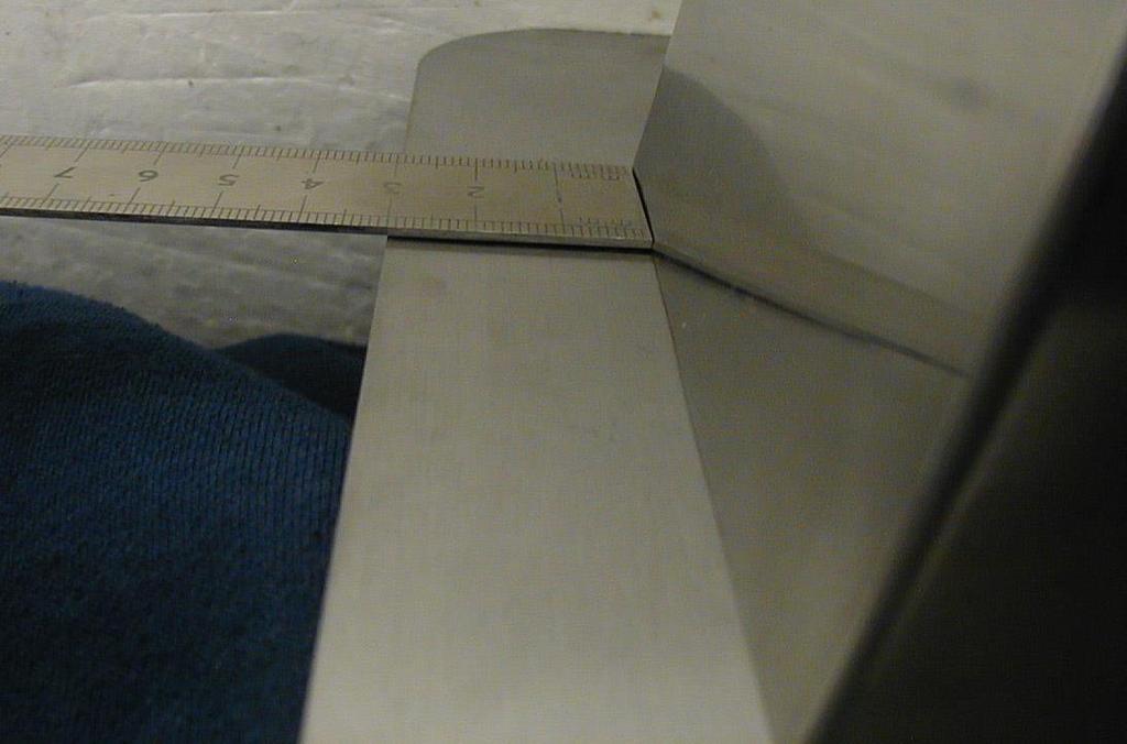
22 3.3.1 Flow Rate Adjustment: The ball valve on the back of the tank should be set to the approximate position as shown below. When the tank is full (displaying PRIME READY FULL) press Boost and change up to C. Place an empty container on the scale and zero the scale. Fully open the dispense dial on the font and at the same time start the timer, close the dial after 20seconds. Note the weight of the water, if it is out of the g range, then adjust the ball valve. Turning the valve handle up so it is inline with the pipe (open) will decrease flowrate from the font. Now screw on the back panel ensuring the hose is not kinking. Repeat the 20second flow test (this is to ensure the hose is not kinked or compressed after the back panel is in place). 22

23 3.3.2 Temperature Calibration : The flow rate must be calibrated before the temperatures as a low flow rate will effect temperature readings. The thermometer used must be calibrated each day by R&D, who will sign the test bench form. The thermistors should be calibrated between C. When the tank is full press Boost and set to 95.5 C, and leave it pumping/circulating for several minutes to ensure an even temperature throughout the tank. Now press all 4 buttons to enter calibration mode. Go to option 2 to first calibrate the Font thermistor. hold the wire thermometer probe under the spout about 10-20mm and set it to note the max reading, now dispense about 1L of water and adjust the offset until the current reading matches the max temp recorded on the thermometer. It is important to allow time for the probe to heat up to give the true max reading so pour slowly at first and then faster. While in calibration mode the tank will not heat so it will be slowly dropping in temperature so you must act quickly when setting your offset to match the max temp reading. The font thermistor is far more sensitive than the tank thermistor, since it is now calibrated you can use it to set the tank temp. There is a temperature drop of 0.5 C between the tank and font outlet (i.e. the tank is always 0.5 C hotter). While in calibration mode you can note the current font temp readout and quickly scroll back to option 1 to set the tank temperature. e.g. if your calibrated font temp is 95 C then set your tank to 95.5 C. If either thermistor offset is greater than +/-1 C then the thermistor should be replaced and recalibrated. If the font thermistor is out of range, it must be replaced before calibrating the tank temperature. Scroll to the Save & Exit option and press Time to Save. 23

24 Above are photos of the tube feeding from the pump into the tank The photo below shows the pipe bending up towards the font. This is the tube which is most likely to have a kink in it. When the back panel is put in place it could press against the tube and cause a kink. If there is a kink you can try to squeeze the tub and reposition it to remove the kink. If it is too long or too short you can try to gently pull or push this tube near the font area to make it slacker or tighter to remove the kink. 24

25 3.4 UBER BOILER PUMP REPLACEMENT Remove the back panel for access to the Nikkiso pump. In the photo below, the water feed from the tank and the pump outlet tube going up to the font can be clearly seen. To replace the pump, remove the two mounting screws from the pump mounting bracket. Release the tube clamps and remove the input and output tubing from the pump. Disconnect the pump wiring at the bullet connectors. Install the replacement pump using the steps above in reverse order. Note: The orientation of the pump head may need to be changed to the orientation shown above. To change the orientation of the pump head, remove the four retaining screws, rotate the head to the required position and replace the four retaining screws. 25


26 3.5 DISPLAY BOARD REPLACEMENT PROCEDURE Note: Prior to replacing the Display, it is recommended that the current settings for the Uber Boiler are recorded so that they may be reset with the new Display. The New Display contains factory settings which may or may not have been changed by the user. Special notice should be made of the Temp Offset settings. These should be the factory settings, as they are to do with the optimum operation of the Boiler and should not be changed by the user. See Service Setup Section for details of how to review the boiler settings Disconnecting the Machine: Turn off the machine and unplug it at the mains and allow it to cool completely. Remove the front service panels, unscrew the 4 screws on each panel and they should drop off. Front Boiler panel Access screws highlighted Removing and Replacing the Display Board Bracket: Unplug all 5 connections from the PCB, you must gently push the plastic tabs back and then pull the connections out. Unscrew the 4 M6 nuts using a 10mm socket driver, be careful as the screen will fall away when all screws are removed. 10mm Socket Driver Remove the transparent protective plastic from the PCB screen. Attach the new screen using the same nuts making sure the orientation is the same but do not fully tighten the nuts yet. There may have been washers on the old display bracket but these are not essential and would be difficult to replace, so you can just use the M6 nuts. 26


27 To make sure your new display is centred & straight look at an angle into the window and see that the metal border on the display is in line with the metal line on the tile. It is OK for the metal border to be slightly visible on the edge furthest away from the driptray/scale. This is since a user is viewing the screen from an angle and will not see this border when looking at the machine from the front When the display is aligned correctly, tighten up the 4 nuts underneath. Now replace all connections as before. 27


28 3.6 UBER BOILER LOADCELL REPLACEMENT Remove the Display Board Bracket, as described previously Loadcell Attachment to Tile: Ensure the loadcell has the connector crimped on. Place 2 x O-rings on the 2 x M5 screws and place 2 x M6 washers between the load cell and the mounting plate. Tighten the 2 x M5 screws into the threaded holes on the loadcell, as shown below. Do not over-tighten the screws or the O-rings will squash out the side. The O-rings are needed to ensure a watertight seal. The washers are needed to to provide operational clearance between the load cell and mounting plate. Note the arrow mark on the loadcell showing which way the load is to be applied. Ensure visually that the holes are centrally in line with the 32mm diameter hole in the driptray Fixing Support Platform to Loadcell: Ensure the platform support is fully sanded and that M4 rivet nuts are attached. Pass the 2 x M5 screws through the top and through the plastic spacers. Now place it on the loadcell and loosely begin to screw them in, locating the threaded holes in the loadcell. Be careful not to press down hard with the screwdriver and overload the loadcell which should only be subjected to 5kg of force or it will break. When it is level and ready to be tightened, place the 4 spacers around the sides and tighten it fully. Again be careful not to press down too hard. The spacers will keep it central. Any suitable spacers can be used to centre the platform. 28


29 3.6.3 Platform Adjustment Screws: Place springs on the 16mm nylon screws and screw them into the rivet nuts. Use a ruler or other straight edge to visually ensure all 4 screw heads are level and approximately 2mm below the surface of the tile be careful not to scratch the tile. (Nylon screws should be used even though stainless steel screws are shown in the photo). Replace the service panel and the machine is ready to use. The machine will require the weighing scale to be recalibrated. 29


30 3.6.4 Font Dial Replacement: Place the font on a large sponge to prevent scratching. Check the dial is polished and sanded fully and can turn in the ball valve and the slide bearing freely. Insert the slide bearing into the font side. Check the position of the ball valve using the guide rod as shown. At this point the valve can be moved freely toward, or away from, the front of the font. When aligned properly, insert the dial using the guide rod to locate it onto the mating ball valve. The black dot on the dial should be visible from the front of the machine in the closed position and visible from the top when open. Look down from the top of the font (not the 30

.")
31 front) and visually examine the dial to see if the dial is parallel to the side of the font. Move the valve forward or back until it is aligned parallel. When parallel, lock the valve in place firmly using a 22mm spanner. Make sure the spanner is covered in tape or otherwise protected to prevent scratching the font. Look at the font from the front to check the dial is parallel with the sides. If this is not parallel then the metal must be bent slightly to adjust it. To do this, remove the dial and slide bearing (the fitting should be fully locked in place at this stage). Now insert a strong screwdriver and lever the fitting up or down until it appears aligned. Refit the slide bearing and dial, and confirm that it s parallel. 31


32 When it is parallel in both directions insert the socket head screw to secure the dial in place. 32

33 To remove the Uber Font Dial and spindle connected to the Font head ball valve, loosen the grub screw, accessible from the centre of the Dial. If the ball valve is found to be dripping/leaking, check that the spindle is not worn, allowing the ball valve to rotate past the Off position. When refitting the ball valve/nozzle assembly, use the nylon slide bearing on the spindle to centre the assembly before tightening the fittings. 33

34 3.7 FONT TO TILE INSTALLATION INSTRUCTIONS Make sure all parts are on clean sponges or polystyrene to stop scratching. Build up a platform so the font can rest on its side at the correct height to be bolted onto the tile. Now place tape around the 4 sides of the opening in the tile to prevent the tubes rubbing off the bare metal cut-out. Insert the locking bracket into the bottom of the Font.(see diagram on next page). Carefully place the Font against the tile. Loosely screw in the 4 bolts. Insert locking bracket inside Service manual bottom April 2017 of Uber the boiler Font 34


35 Loosely screw in 4x M6 bolts Aligning the Font on the Tile: : Check that the back of the font is square with the tile, to do this measure the distance from the edge of the tile to the font, it should be equal on both left and right corners, the dimension itself is not important. When confirmed square, fully tighten the 4 bolts down. 35
36 36

37 3.7.2 Connecting the Font Tubing: Tape on edges to stop damage to tubes during installation. Connect the return silicone tube marked black to the ball valve on the tank. Connect the other font tube to the thermistor tee piece. Connect the drip tray overflow to the tank overflow. Secure all hoses with plastic hose clips, F clips on the tank tit and ball valve, G clips on the Tee piece. Ensure the hose clips are turned in towards the tank so they do not crash against the surround panel. Thermistor T-Piece 37


38 3.8 WATER LEVEL PROBES INSTALLATION INSTRUCTIONS The new software requires that the 3 level probes are connected if the Uber already has the 3 probes connected no change is required. In earlier version of the Uber Boiler only 2 probes may have been connected. This kit contains a probe wiring loom, see below. This should be connected to the Probes as in the photo below. Top probe is Red Wire, Middle probe is Green Wire and bottom Probe is Yellow Wire. Red Wire Green Wire Yellow Wire Connector to PCB Water Level Probes Harness Update An updated, generic water level probes harness is now available as a spare part P/N: The original bullet connectors which attach to the water level probes have been replaced with ring connectors and there are wires for connection to the dispense push-button on pushbutton models. 38

39 4.1 Uber Boiler Functional Diagram 39
40 4.2 Spare Parts Schematic Item No. Part No. Description Qty Push Button Metal Domed 16mm Uber Display Window Load Cell 5Kg M5 with Connector Drain Valve 1/4" BSP Flow Control Dial Uber Bearing Slide Nylon 12.5 x 18 x 24 x 18 x 2 1 6a Bearing Slide Nylon 13.2 x 18 x 24 x 18 x Elbow 1/4" BSP Female x 3/8" BSP Male Adaptor 1/8" F x 1/4" M (Gauge) O-Ring for Sight Glass Fastener - Ball Socket Ball Head - Steam Pipe PCB Uber Display 4 x 20 Characters Spacer Polystyrene 5.2 x 10 x Steam Spout Set Adaptor 1/4"BSP 6S/S Spout Adaptor Aerator Aerator Tomlinson M205Za 1 40
41 Item No. Part No. Description Qty PCB Ecoboiler Slave Valve Inlet Solenoid 240V 3/4" BSP Leg 50mm Nylon 22mm Diameter Switch Power On/Off Element 2.8kW 230V M-Shape Long T-Piece 1/2" 36 x 60mm T-Piece 1/4" BSP F Equal Chrome Thermister M5 Brass Submersible Thermister Assembly Probe Assembly Sub-Con (40mm Tab) Pump Nikkiso Water Level Probes Wiring Harness 1 41
42 4.3 Electrical Schematic 42
43 43
Marco Beverage Systems Ltd. INSTRUCTIONS FOR MODEL Revision 9 th Mar Uber Boiler
 Marco Beverage Systems Ltd. INSTRUCTIONS FOR MODEL Revision 9 th Mar 2010 Uber Boiler P/N: 1000680 Uber Boiler 6L 2.8kW P/N: 1000681 Uber Boiler 2L 2.8kW MARCO is an ISO9001:2000 Registered Company. Water
Marco Beverage Systems Ltd. INSTRUCTIONS FOR MODEL. Uber Boiler
 Marco Beverage Systems Ltd. INSTRUCTIONS FOR MODEL Uber Boiler Part/Model Number: 1000680# 1000681 (where # is a suffix of one or more alphanumeric characters) INCORPORATING SOFTWARE 1.10 Water pressure
Marco Beverage Systems Ltd. INSTRUCTIONS FOR MODELS
 Marco Beverage Systems Ltd. INSTRUCTIONS FOR MODELS Ecoboiler UC4L 2.4kW (1000740#) Ecoboiler UC10L 2.8kW (1000741#) Ecoboiler UC10L 5.6kW (1000742#) Ecoboiler UC4L 1.5kW 110V (1000747) Ecosmart UC4L 2.4kW
Marco Beverage Systems Ltd.
 Marco Beverage Systems Ltd. INSTRUCTIONS FOR MODELS ECOSMART PB10, ECOSMART PB10 Hi Deck ECOSMART T10 (P/N: 1000677#, 1000678#, 1000674#) Water pressure : 5-50 psi (min.-max.)35-345 kpa (min.-max.) Marco
MIX Boiler & Font Range Service Manual
 MIX Boiler & Font Range Service Manual 1000870# 1000871# 1000875# 1000880# 1000887# 1000878 1000879 2300268 www.marcobeveragesystems.com Ireland Tel: +353 (1) 295 2674 UK Tel: +44 (0207) 2744577 Service
INSTRUCTIONS FOR MODEL
 Marco Beverage Systems Ltd. INSTRUCTIONS FOR MODEL Font Uber Style Marco Beverage Systems Limited. 63d Heather Road, Sandyford Industrial Estate, Dublin 18. Ireland Tel: +353 (0)1 295 2674 Ireland Fax:
Mix Boiler & Font Range ( #, #, #, , )
") Mix Boiler & Font Range (1000870#, 1000871#, 1000880#, 1000878, 1000879) Service Manual Marco Beverage Systems Ltd. 63d Heather Road, Sandyford Industrial Estate, Dublin 18, Republic of Ireland Ireland
Mix Boiler & Font Range (1000870#, 1000871#, 1000880#, 1000878, 1000879) Service Manual Marco Beverage Systems Ltd. 63d Heather Road, Sandyford Industrial Estate, Dublin 18, Republic of Ireland Ireland
Ecoboiler T20 & T30 SERVICE MANUAL. Marco Beverage Systems Ltd. 63d Heather Road, Sandyford Industrial Estate, Dublin 18, Republic of Ireland
 Ecoboiler T20 & T30 SERVICE MANUAL Marco Beverage Systems Ltd. 63d Heather Road, Sandyford Industrial Estate, Dublin 18, Republic of Ireland Ireland Tel: (01) 295 2674 Ireland Fax: (01) 295 3715 UK Tel:
SERVICE MANUAL. Ecoboiler Model range: T20 ( ) T30 ( )
 T30 ( )") SERVICE MANUAL Ecoboiler Model range: T20 (1000662) T30 (1000663) Marco Beverage Systems Ltd. 63d Heather Road, Sandyford Industrial Estate, Dublin 18, Republic of Ireland Ireland Tel: (01) 295 2674 Ireland
SERVICE MANUAL Ecoboiler Model range: T20 (1000662) T30 (1000663) Marco Beverage Systems Ltd. 63d Heather Road, Sandyford Industrial Estate, Dublin 18, Republic of Ireland Ireland Tel: (01) 295 2674 Ireland
Instruction Manual Machine P/N: # & #
 Instruction Manual Machine P/N: 1000830# & 1000831# 1 CONTENTS 1. INFORMATION...3 1. Introduction...3 2. Safety...3 3. Warning Notes...3 4. Contact...4 5. Electrical Installation Procedure...4 6. Plumbing
EcoSmart boiler SERVICE MANUAL
 EcoSmart boiler SERVICE MANUAL Marco Beverage Systems Ltd. 63d Heather Road, Sandyford Industrial Estate, Dublin 18, Republic of Ireland Ireland Tel: (01) 295 2674 Ireland Fax: (01) 295 3715 UK Tel: (0207)
Ecoboiler SERVICE MANUAL. Marco Beverage Systems Ltd. 63d Heather Road, Sandyford Industrial Estate, Dublin 18, Republic of Ireland
 Ecoboiler SERVICE MANUAL Marco Beverage Systems Ltd. 63d Heather Road, Sandyford Industrial Estate, Dublin 18, Republic of Ireland Ireland Tel: (01) 295 2674 Ireland Fax: (01) 295 3715 UK Tel: (0207) 274
UNDERCOUNTER SERVICE MANUAL. Ecoboiler UC4L 2.4kW Ecoboiler UC10L 2.8kW Ecoboiler UC10L 5.6kW Ecosmart UC4L 2.
 UNDERCOUNTER SERVICE MANUAL Ecoboiler UC4L 2.4kW 1000740 Ecoboiler UC10L 2.8kW 1000741 Ecoboiler UC10L 5.6kW 1000742 Ecosmart UC4L 2.4kW 1000750 Ecosmart UC10L 2.8kW 1000751 Ecosmart UC10L 5.6kW 1000752
AQUARIUS 45 MARINE SERVICE MANUAL
 AQUARIUS 45 MARINE SERVICE MANUAL CONTENTS: PAGE 1. INTRODUCTION 3 2. SAFETY INSTRUCTIONS 4 3. BASIC INSTRUCTIONS 5 3.1. Installation Details 5 3.2. Operating the Boiler for the First Time 6 3.3. Troubleshooting
SERVICE MANUAL. Marco Beverage Systems Ltd. 63d Heather Road, Sandyford Industrial Estate, Dublin 18, Republic of Ireland
 SERVICE MANUAL Under Counter Range, Model UC45 1000743 (2.8kW) 1000744 (5.6kW) 1000744US (5.6kW) 1000745 (8.4kW) 1000753 (2.8kW) 1000754 (5.6kW) 1000755 (8.4kW) 1000743A (2.8kW) 1000744A (5.6kW) 1000745A
T5 ( ) T10 ( ) PB5 ( ) PB10
 T10 ( ) PB5 ( ) PB10") SERVICE MANUAL Ecoboiler Model range: T5 (1000660) T10 (1000661) PB5 (1000665) PB10 (1000666) Marco Beverage Systems Ltd. 63d Heather Road, Sandyford Industrial Estate, Dublin 18, Republic of Ireland Ireland
SERVICE MANUAL Ecoboiler Model range: T5 (1000660) T10 (1000661) PB5 (1000665) PB10 (1000666) Marco Beverage Systems Ltd. 63d Heather Road, Sandyford Industrial Estate, Dublin 18, Republic of Ireland Ireland
SERVICE MANUAL UBER FONT
 SERVICE MANUAL UBER FONT Marco Beverage Systems Ltd. 63d Heather Road, Ireland Tel: (01) 295 2674 Ireland Fax: (01) 295 3715 Sandyford Industrial Estate, Dublin 18, Republic of Ireland UK Tel: (0207) 274
CONTENT PAGE INFORMATION INSTALLATION BREWER SETUP BREWING CLEANING KEY BREWER GRINDER MANUAL MODE DILUTION GRINDER MODE PACKS MODE
 1900097 1JET6 TWIN CONTENT PAGE INFORMATION 3 INSTALLATION 6 BREWER GRINDER 6 7 BREWER SETUP 11 BREWING 12 MANUAL MODE DILUTION GRINDER MODE PACKS MODE 12 14 15 17 CLEANING 19 KEY READ OPERATORS MANUAL
Jet 6 Twin SERVICE MANUAL
 Jet 6 Twin SERVICE MANUAL Service manual Aug 2017 - Jet 6 Twin Page 1 of 17 Marco Beverage Systems Ltd. 63d Heather Road, Sandyford Industrial Estate, Dublin 18, Republic of Ireland Ireland Tel: (01) 295
User and Installation Instructions. Wall Mounted Water Boiler WMB3F/B and WMB3F/W IS435 ECN3461
 User and Installation Instructions Wall Mounted Water Boiler WMB3F/B and WMB3F/W IS435 ECN3461 Dear Customer Thank you for purchasing this Lincat product. With correct use and careful maintenance as described
Zip Autoboil Installation and Operating Instructions
 Zip Autoboil Installation and Operating Instructions 315052 Zip Autoboil 15 Litre White 313051 Zip Autoboil 15 Litre Stainless Steel 325052 Zip Autoboil 25 Litre White 325051 Zip Autoboil 25 Litre Stainless
SCHWAN INSTALLATION GUIDE
 SCHWAN INSTALLATION GUIDE For Schwan Versatap SC52E Instant Hot Cold Filtered Water FOR SERVICE OR ASSISTANCE CALL MERQUIP ON 0800 636 0 636. Schwan recommends that a qualified tradesperson installs your
MK 8706 / MB 8706 CONCEALED THERMOSTATIC SHOWER VALVE INSTALLATION GUIDE
 MK 8706 / MB 8706 CONCEALED THERMOSTATIC SHOWER VALVE INSTALLATION GUIDE DIMENSIONS 150mm 55mm 200mm 67mm Hot water ¾ BSP Parallel Cold water ¾ BSP Parallel 160mm x 120mm aperture behind face plate for
Aquamixa. Thermo. Thermostatic shower valve with manual bath fill
 Aquamixa Thermo Thermostatic shower valve with manual bath fill Aquamixa Thermo thermostatic shower valve with manual bath fill installation instuctions page 1 Shower systems Aquamixa Thermo (300.01) with
Installation, Operating and Servicing Instructions
 Installation, Operating and Servicing Instructions Wall Mounted Water Boiler WMB3F/B,WMB3F/W Please make a note of your product details for future use: Date Purchased: Model Number: Serial Number: Dealer:
Thermostatic bar mixer valve with adjustable head Installation guide
 Bar valve Thermostatic bar mixer valve with adjustable head Installation guide Index Introduction p.3 - Safety information p.3 - Product specification p.3 Connection to supplies p.3 - Flushing p.4 - Filters
Thermostatic Concealed Shower Valve
 Thermostatic Concealed Shower Valve Product may differ from image. Please retain this booklet for future aftercare reference Component Breakdown - Three Handle Valve Component breakdown Two Handle Valve
Autofill wall mounted water. boiler. Getting the best from your water. boiler. Please read and keep these instructions
 Autofill wall mounted water boiler Please read and keep these instructions For Burco wall mounted boilers 76700 (SKU 444448534), 76702 (SKU 444448546), & 76704 (SKU444448548) Getting the best from your
HWD-2110 Hot Water Dispenser
 User s Guide t f Touch Function Selector Technology HWD-2110 Hot Water Dispenser. NOTICE TO INSTALLER: Please leave this book with the machine. Temperature On Demand US design patent applied for. Other
4L Instant Water Boiler Instructions for Use
 Power Details: 220-240Va.c. 50Hz-60Hz 2200-2600W Capacity: 4.0L Accessories: 2 Water aid trays Water Filters are not included and can be purchased separately Item Code 10747 IMPORTANT NOTES FOR YOUR INSTANT
SERVICE MANUAL DISHWASHERS DIVA ACCESSIBILITY DISHWASHERS
 SERVICE MANUAL DISHWASHERS DIVA ELECTROLUX HOME PRODUCTS S.p.A. Publication no. Spares Operations Italy Corso Lino Zanussi,30 I - 33080 PORCIA /PN (ITALY) 599 38 70-09 Fax +39 0434 394096 EN DISHWASHERS
The Professional s Choice
 CPF Series Models: CPF2100, CPF210, CPF310, CPF4100-3, CPF4100-6 & CPF6100 Auto-Fill Catering Water Boiler With Integrated Multi-Filter Installation And User Instructions The Professional s Choice INSTANTA
Autofill counter top water boiler
 Autofill counter top water boiler Please read and keep these instructions For Burco counter top water boilers 76500 (SKU 444448531) and 76502 (SKU 444448533) Getting the best from your water boiler Remove
HWD-2105 Hot Water Dispenser. NOTICE TO INSTALLER: Please leave this book with the machine.
 User s Guide t f Touch Function Selector Technology HWD-2105 Hot Water Dispenser. NOTICE TO INSTALLER: Please leave this book with the machine. Temperature On Demand US design patent applied for. Other
Manual / Handbuch Spare parts list / Ersatzteilliste
 Manual / Handbuch Spare parts list / Ersatzteilliste Equipment Imp.-Exp. GmbH Zitterpappelweg 9 D - 22391 Hamburg Tel.: + 49 40 60009468-0 Fax: + 49 40 536 75 01 E - M a i l : i n f o @ w e s c o - n a
MIDAS. Installation instructions 110/220
 MIDAS Installation instructions 110/220 INDEX INTRODUCTION Page 3 Safety information Page 3 Product specification Page 3 Important information CONNECTION TO SUPPLIES Page 4 Flushing Page 4 Filters Page
What to expect from your water softener
 What to expect from your water softener All water softeners work on the same basic principal. Hard water flows through a bed of resin and the calcium and magnesium, the minerals that are responsible for
INSTALLATION AND OPERATION INSTRUCTIONS LC-D SERIES COFFEE CONCENTRATE BREWER WITH DIGITAL ELECTRONIC CONTROL CENTER
 107353 1-00 INSTALLATION AND OPERATION INSTRUCTIONS LC-D SERIES COFFEE CONCENTRATE BREWER WITH DIGITAL ELECTRONIC CONTROL CENTER PLUMBER'S INSTALLATION INSTRUCTIONS CAUTION: Power to brewer must be OFF
SCHWAN INSTALLATION GUIDE
 1 SCHWAN INSTALLATION GUIDE For Schwan SC60 FOR SERVICE OR ASSISTANCE CALL MERQUIP ON 0800 636 0 636. Schwan recommends that a qualified tradesperson installs your Schwan system. 2 INFORMATION AND SAFETY
Quartz. Thermo. Concealed shower valve with adjustable head. Quartz Thermo installation guide page 1
 Quartz Thermo Concealed shower valve with adjustable head Quartz Thermo installation guide page 1 Shower systems Components Quartz Thermo built-in shower valve with adjustable head QZ3111 Quartz Thermo
Dream DCV. Thermostatic Dual control mixer valve range. Installation guide
 Dream TM DCV Thermostatic Dual control mixer valve range Installation guide Index Introduction p.3 - Safety information p.3 - Product specification p.3 Connection to supplies p.4 - Pipe sizing p.4 - Flushing
Hot Chocolate Dispenser
 Hot Chocolate Dispenser Instruction manual Model: CN219-A AU Telephone Helpline: 1300225960 Safety Tips Position on a flat, stable surface. A service agent/qualified technician should carry out installation
Enzo Concealed Shower Mixing Valve
 Enzo Concealed Shower Mixing Valve EZ40010CP, EZ40013CP & EZ40014CP Installation and Maintenance Instructions In this procedure document we have endeavoured to make the information as accurate as possible.
Models: GW/R-T GW/R-2-T GW/R-3-T
 Part# GW/R-T-OM 1/12/04 TN Models: GW/R-T GW/R-2-T GW/R-3-T This manual contains important information concerning the installation and operation of the gun washers listed above. Read manual thoroughly
Introduction... 3 Setup & Suggestions... 4 Basic Use... 4 Setting Time... 4 Setting Temperature... 5 Setting Height / Pressure...
 Table of of Contents Contents... 2 Introduction... 3 Setup & Suggestions... 4 Basic Use... 4 Setting Time... 4 Setting Temperature... 5 Setting Height / Pressure... 6 Aligning the pedestal... 6 Guidelines
JOHN DEERE GATOR HPX/XUV 2 PASSENGER HEATER INSTALLATION INSTRUCTIONS (p/n: 9PH20S30)
") P. 1 of 12 JOHN DEERE GATOR HPX/XUV 2 PASSENGER HEATER INSTALLATION INSTRUCTIONS (p/n: 9PH20S30) Item: Qty: Description: 1 2 1 x 1 x 5/8 Tee Fitting 2 2 Plastic Snap-in Hose Grommet 3 4 1-1/2" Hose Clamps
P. 1 of 12 JOHN DEERE GATOR HPX/XUV 2 PASSENGER HEATER INSTALLATION INSTRUCTIONS (p/n: 9PH20S30) Item: Qty: Description: 1 2 1 x 1 x 5/8 Tee Fitting 2 2 Plastic Snap-in Hose Grommet 3 4 1-1/2" Hose Clamps
MODEL A5-2 SOLVENT & WATER RECOVERY SYSTEMS (EXPLOSION PROOF UNITS)
") MODEL A5-2 SOLVENT & WATER RECOVERY SYSTEMS (EXPLOSION PROOF UNITS) FOR PROPER AND SAFE USE OF THIS CHEMCHAMP EQUIPMENT, PLEASE FOLLOW THIS DOCUMENT AND LOCAL AUTHORITY. KEEP THIS DOCUMENT FOR FUTURE REFERENCE.
MODEL A5-2 SOLVENT & WATER RECOVERY SYSTEMS (EXPLOSION PROOF UNITS) FOR PROPER AND SAFE USE OF THIS CHEMCHAMP EQUIPMENT, PLEASE FOLLOW THIS DOCUMENT AND LOCAL AUTHORITY. KEEP THIS DOCUMENT FOR FUTURE REFERENCE.
Enzo Safe Touch Thermostatic Shower EZ10010CP & EZ10014CP
 Enzo Safe Touch Thermostatic Shower EZ10010CP & EZ10014CP Installation and Maintenance Instructions In this procedure document we have endeavoured to make the information as accurate as possible. We cannot
Quartz. Digital. Concealed with adjustable height and fixed head. Quartz Digital concelaed adjustable/fixed installation instuctions page 1
 Quartz Digital Concealed with adjustable height and fixed head The Waste Electrical and Electronic Equipment (Producer Responsibility) Regulation 2004 This product is outside the scope of the European
Installation & Operating Guide
 5-036 HOT WATER TANK Installation & Operating Guide Read all instructions thoroughly. Keep this guide for future reference. Proof of purchase is required for Warranty. Staple receipt or proof of purchase
The Professional s Choice
 SureFlow compact range: 1000-C & 1000-M Auto-Fill Catering Water Boiler Installation And User Instructions The Professional s Choice CONTENTS CONTENTS & INTRODUCTION 2 SAFETY & ENVIRONMENTAL INFORMATION
FLAVIA CREATION C500 User Guide
 FLAVIA CREATION C500 User Guide www.marsdrinks.com CONTENTS Page Safety & Installation Guidelines... 1-2 Brewer Layout... 3 Setting up your Brewer... 4-5 Selecting Cups to Use... 6 The FLAVIA CREATION
SuperKlean Washdown Products
 February 2012 DURAMIX 8000 INSTALLATION AND MAINTENANCE INSTRUCTIONS **DO NOT THROW AWAY AFTER INSTALLATION** **SAVE AND DISPLAY PROMINENTLY WHERE THIS EQUIPMENT IS USED** WARNING HIGH PRESSURE AND HOT
Recirculating Chiller RC350G-RC400G RC1400G-RC3000G. Operating Manual
 Recirculating Chiller RC350G-RC400G RC1400G-RC3000G Operating Manual Part No 09931/Issue 10 Page 2 April 2010 CONTENTS 1 Safety 4 2 Installation 5 2.1 Connection for closed loop circulation 6 2.2 Connection
Zip Autoboil. Installation and Operating Instructions
 Zip Autoboil Installation and Operating Instructions 303052 Zip Autoboil 3 Litre White 303051 Zip Autoboil 3 Litre Stainless Steel 305052 Zip Autoboil 5 Litre White 305051 Zip Autoboil 5 Litre Stainless
Enzo and Enzo Deluxe Safe Touch Thermostatic Shower EN10031CP & EN10035CP
 Enzo and Enzo Deluxe Safe Touch Thermostatic Shower EN10031CP & EN10035CP Installation and Maintenance Instructions In this procedure document we have endeavoured to make the information as accurate as
THE BOILING WATER DISPENSER INSTALLATION & OPERATING INSTRUCTIONS IMPORTANT: READ AND SAVE THESE INSTRUCTIONS FOR THE BENEFIT OF THE USER
 THE BOILING WATER DISPENSER INSTALLATION & OPERATING INSTRUCTIONS IMPORTANT: READ AND SAVE THESE INSTRUCTIONS FOR THE BENEFIT OF THE USER Thank you for choosing a quality Redring product manufactured by
OPERATING AND MAINTENANCE MANUAL
 Enter Serial No. here. In the event of an enquiry please quote this serial number. www.monoequip.com OPERATING AND MAINTENANCE MANUAL COMPACT SERIES 643 3 TRAY OVEN FILE 52 643 compact 3 TRAY RevA17 10-4-17
Installation & Operating Guide
 HOT WATER DISPENSER Installation & Operating Guide Read all instructions thoroughly. Keep this guide for future reference. Proof of purchase is required for Warranty. Staple receipt or proof of purchase
INTA ION MODERN BAR / BATH SHOWER MIXER CP
 INTA ION MODERN BAR / BATH SHOWER MIXER 910000CP INSTALLATION, OPERATION AND MAINTENANCE INSTRUCTIONS PLEASE LEAVE THESE INSTRUCTIONS WITH THE USER Page 1 of 10 INTRODUCTION This installation guide has
Aquatique. Shower heads. Fixed and adjustable height heads. Aquatique shower kits installation guide page 1
 Aquatique Shower heads Fixed and adjustable height heads Aquatique shower kits installation guide page 1 Components Aquatique adjustable height shower kit concealed Chrome 560.01 / Gold 560.04 Aquatique
OC Series - Automatic coffee machines. OLC1 Lucia High performance liquid coffee dispenser. Users Handbook - 1 -
 OLC1 Lucia High performance liquid coffee dispenser Users Handbook - 1 - Every effort has been made to ensure that the information contained in this manual is up to date and correct. However, the author,
PRO 2000i LOW LEVEL DEPOSITOR
 DEPOSITORS AND AUTOMATED CAKE PRODUCTION SYSTEMS PRO 2000i LOW LEVEL DEPOSITOR OPERATION AND SPARE PARTS MANUAL Serial No. PR2L- (Please quote this number when ordering spares, and making service calls)
Page 1 of 18. Part# /5/2013
 Part# 1002655-06 8/5/2013 This manual contains important information concerning the installation and operation of the gun washers listed above. Read manual thoroughly and keep for future reference INSTRUCTIONS
Mira Sport Max with Airboost
 Mira Sport Max with Airboost 9.0 & 10.8 kw These instructions must be left with the user Installation Guide 1 INTRODUCTION our instructions and recommendations. inside the shower. The Mira Sport Max with
OPERATING & SERVICE PARTS MANUAL HDS-215 COMBINATION SHRINK SYSTEM
 OPERATING & SERVICE PARTS MANUAL HDS-215 COMBINATION SHRINK SYSTEM FOR HOT KNIFE AND IMPULSE MACHINES READ ALL INSTRUCTIONS CAREFULLY BEFORE OPERATING EQUIPMENT TABLE OF CONTENTS Electrical Requirements
Issue 4 Oct Panamatic Top loading Maxi & Optima 3 Installation
 Issue 4 Oct 2005 Panamatic Top loading Maxi & Optima 3 Installation Please Do handle the unit with care, to avoid scuffs and scratches during installation. Do not over-tighten plumbing or any other mechanical
Minimalist Bottom Outlet Thermostatic Bar Shower. Telephone Product Specification
 Product Specification ~ Minimum Working Pressure 0.5 bar ~ Maximum Working Pressure 4.0 bar ~ Cold Water Supply Temp 4-20 c ~ Hot Water Supply Temp 55-85 c ~ Fixing Centres 150mm +/- 20mm ~ Outlet size
Service Parts
 GM Operator Manual !!!! WARNING Before installation and commisioning, you must read the safety instructions and warnings carefully and all the warning labels attached to the equipment. IMPORTANT Failure
BOILING UNIT REDITAP. Installation and User Guide. IMPORTANT: This booklet should be left with the user after installation and demonstration
 in tap Boiling water to in tap sink Drain Valve (as high as possible) REDITAP CONNECTION SUMMARY Amp mains supply cold mains water into in tap optional filter cold water in hot water BOILING UNIT Installation
ELECTRIC WATER BOILER
 JJ3 ELECTRIC WATER BOILER OWNER S MANUAL Click here for Parts List Manual Part No: 930150-01 Electric Water Boiler - 1 Model No. Product Description Rev. Date Jackson Junior Boiler JJ3 Jackson Junior Boiler
Digital Marine Exhaust Temperature Alarm
 Digital Marine Exhaust Temperature Alarm Model: SM007D/S INTRODUCTION COMPONENTS Marine water cooled exhaust systems are designed to withstand temperatures of up to about 120 C. However the exhaust gases
User and Installation Instructions. Electric Auto-Fill Water Boilers EB3F, EB4F, EB6F, EB6TF IS339 ECN3539
 User and Installation Instructions Electric Auto-Fill Water Boilers EB3F, EB4F, EB6F, EB6TF IS339 ECN3539 Dear Customer Thank you for purchasing this Lincat product. With correct use and careful maintenance
OPERATING INSTRUCTIONS
 OPERATING INSTRUCTIONS BAKE-KING KING OVEN BEDIENUNGSANLEITUNG MODE D EMPLOI GEBRUIKSAANWIJZING PLEASE READ CAREFULLY (Rev 1; 01/03/2012 INSTALLATION INSTRUCTIONS We recommend that wherever possible, the
ROTA-SPRAY PROCESSOR MODEL 1210 (ROTARY-JET) INSTRUCTIONS MEGA PART NO: &
 INSTRUCTIONS MEGA PART NO: &") ROTA-SPRAY PROCESSOR MODEL 1210 (ROTARY-JET) INSTRUCTIONS MEGA PART NO: 500-702 & 500-713 PLEASE READ IMPORTANT UNPACKING INSTRUCTIONS 1. Carefully consider where the unit will be located. It should be
ROTA-SPRAY PROCESSOR MODEL 1210 (ROTARY-JET) INSTRUCTIONS MEGA PART NO: 500-702 & 500-713 PLEASE READ IMPORTANT UNPACKING INSTRUCTIONS 1. Carefully consider where the unit will be located. It should be
Coffee Machine Zia series
 Coffee Machine CoEx Brewer - Freshbrew EN Picture: Filename: Zia-6000_9CND_UserManual_5DUCNP20a_EN_v01-02.docx Disclaimer Manufacturer: Although this user manual has been put together with the utmost care,
Table of Contents. FETCO, and Driven To Pioneer Innovation are trademarks or trade names of Food Equipment Technologies Company.
 www.fetco.com Hot Water Dispensers User s Guide Maritime Versions Rated IP44 Table of Contents Contact Information... 2 Specifications... 2 Dimensions... 3 Installation... 4 Operating Instructions...6
Installation Instructions EFS Hand Washing Station
 Installation Instructions EFS Hand Washing Station Both water and soap are sequenced and dispensed from outlet. Override button allows for non potable, water-only dispensing. Lighted icons indicate the
SAFETY OPERATION & MAINTENANCE MANUAL X-405 CARPET EXTRACTOR This unit is intended for commercial use.
 SAFETY OPERATION & MAINTENANCE MANUAL X-405 CARPET EXTRACTOR This unit is intended for commercial use. READ AND FOLLOW ALL INSTRUCTIONS, WARNINGS AND CAUTIONS BEFORE USING THIS EXTRACTOR Address: 777 South
WATER BOILER METOS MARINE WKI MG MW,
 WATER BOILER METOS MARINE WKI MG4164349MW, 4164349, 4164354, 4164356 User manual WKI10n 27.10.2015 27.10.2015 Water boiler Metos Marine WKI M L K J A B I C H G F D E fig. 1 / Abb. 1 2 Water boiler Metos
Where the tap has a removable aerator on the spout exit it can be removed and cleaned periodically to maintain optimum flow performance.
 TAP6000 3 in Hot Tap Guarantee (UK only): 04-7 Your tap has the benefit of a comprehensive manufacturer s guarantee, details of which are shown on your Proof of Purchase Document. Any claim during the
Installation Instructions. Filtered Chilled drinking water for commercial kitchens and tea rooms.
 Installation Instructions Zip HydroTap Filtered Chilled drinking water for commercial kitchens and tea rooms. Affix Model Number Label Here 801525 801525 - Zip HydroTap Installation Instructions - Nov.
SAFETY AND OPERATING MANUAL
 SAFETY AND OPERATING MANUAL HOT WATER ELECTRIC WATER BLASTERS Read Safety & Operating Instructions Before Commencing Operation THESE INSTRUCTIONS MUST BE READ AND ADHERED TO BEFORE OPERATING THIS MACHINE.
Installation guide Billi B-3000 Sparkling Dual levered slimline tap option
 Installation guide Billi B-3000 Sparkling Dual levered slimline tap option Installation requirements. IMPORTANT: This Billi appliance is to be installed by a licensed trades person in accordance with AS/NZS
INSTALLTION FOR THERMOSTATIC VALVES
 SS-TH1000 ½ THERMOSTATIC VALVE SS-TH3000 ¾ THERMOSTATIC VALVE SS-TH2000 ½ THERMOSTATIC VALVE WITH BUILT IN VOLUME CONTROL SS-TH4000 ¾ THERMOSTATIC VALVE WITH BUILT IN VOLUME CONTROL Features: Ability to
Water Softener Installation Guide Effective for all Softeners from our Range
 Water Softener Installation Guide Effective for all Softeners from our Range Planning Your Installation Always observe the water byelaws. Ensure there is only one rising main, that you have allowed space
Basin Set INSTALLATION INSTRUCTIONS
 P24130-CR, P24130-LV, P24131-CR, P24131-LV, P24400-CR, P24400-LV, P24401-CR, P24401-LV, P24402-CR, P24402-LV, P24500-LV, P24500-TT 1 of 5 INSTALLATION INSTRUCTIONS Thank You For Choosing Kallista We appreciate
Lavatory Faucet INSTALLATION INSTRUCTIONS P24490-CR, P24490-LV, P24491-CR, P24491-LV, P24492-CR, P24492-LV, P24700, P24705, P24706, P24736, P24800
 P24490-CR, P24490-LV, P24491-CR, P24491-LV, P24492-CR, P24492-LV, P24700, P24705, P24706, P24736, P24800 2018 1 of 7 KALLISTA THANK YOU FOR CHOOSING KALLISTA We appreciate your commitment to KALLISTA quality
Bx OVEN SET UP AND OPERATION OF OVEN AND CONDENSER UNIT (IF FITTED) CLASSIC
 CLASSIC") www.monoequip.com OVEN SERIAL NO. OVEN CODE 149 150 153 156 158 159 180 CONDENSER SERIAL No. (IF FITTED) In the event of an enquiry please quote these numbers. Bx OVEN SET UP AND OPERATION OF OVEN AND
www.monoequip.com OVEN SERIAL NO. OVEN CODE 149 150 153 156 158 159 180 CONDENSER SERIAL No. (IF FITTED) In the event of an enquiry please quote these numbers. Bx OVEN SET UP AND OPERATION OF OVEN AND
INSTALLATION MANUAL. TBA Evaporative Cooler. (English) (TBA) ILL1456-A
 (TBA) ILL1456-A") INSTALLATION MANUAL TBA Evaporative Cooler ILL1456-A (English) (TBA) TIMER AUTO COOL ILL1128-A ILL239-D TIMER AUTO COOL ILL1128-A ILL972-A Step 1 Step 2 Step 3 Step 4 SAFETY FIRST! 1. Read & understand
INSTALLATION MANUAL TBA Evaporative Cooler ILL1456-A (English) (TBA) TIMER AUTO COOL ILL1128-A ILL239-D TIMER AUTO COOL ILL1128-A ILL972-A Step 1 Step 2 Step 3 Step 4 SAFETY FIRST! 1. Read & understand
Zip HydroTap Miniboil
 Installation and Operating Instructions Zip HydroTap Miniboil Boiling and Ambient drinking water for kitchens and the home. Miniboil BA tap HydroTap Classic BA tap Affix Model Number Label Here 89585 GP
Installation Instructions and User Guide. Thermostatic Recessed Dual Control Shower Valve. Models covered: CAS SHCVO C, COB SHCVO C, ORB SHCVO C,
 Installation Instructions and User Guide Thermostatic Recessed Dual Control Shower Valve Models covered: CAS SHCVO C, COB SHCVO C, ORB SHCVO C, EXD SHCVO C, SAI SHCVO C, GLR SHCVO C, BRG SHCVO C, HOU SHCVO
ECOJET EJ-10E & EJ-7E ELECTRIC CONVECTION STEAMER W/TWIN GENERATORS PARTS AND SERVICE MANUAL
 ECOJET EJ-10E & EJ-7E ELECTRIC CONVECTION STEAMER W/TWIN GENERATORS PARTS AND SERVICE MANUAL EFFECTIVE JULY 31, 2014 Superseding All Previous Parts Lists. The Company reserves the right to make substitution
Important Safeguards. Topic 2 SAVE THESE INSTRUCTIONS - FOR HOUSEHOLD USE ONLY SAVE THESE INSTRUCTIONS - FOR HOUSEHOLD USE ONLY 3
 User s Manual Index Topic Important safeguards 03 Safety features 05 Parts and accessories 05 Before first use 06 Operating instructions 06 Programme settings 08 Care and cleaning 09 Pressure canning guide
MINIATURE THERMOSTATIC VALVE
 SS-TH500-1/2 Features: Ability to pre-select water temperature thus conserving water Compensates for water pressure fluctuations preventing scalding Safety button at 100 F prevents accidental scalding
568X, 587X, 588X Series
 Please read and save this Repair Parts Manual. Read this manual and the General Operating Instructions carefully before attempting to assemble, install, operate or maintain the product described. Protect
THERMAPHASE INSTALLATION AND OPERATING INSTRUCTIONS
 Page 1 of 10 THERMAPHASE INSTALLATION AND OPERATING INSTRUCTIONS Purpose of Manual The purpose of this manual is to provide operating, servicing and repair instructions for the Summit standard models ThermaPhase
Rheem Australia Pty Ltd ABN
 Rheem Australia Pty Ltd ABN 21 098 823 511 SERVICE INSTRUCTIONS Lazer 441, 451, 741, 751, 761, 771, 781 & 791 Series TM001 Revision: AD Issued: Jan 14 Lazer 1 & 2 Silhouette (Designer Series) Classic (Modular
Quartz. Digital. Bath with bath waste filler. Quartz Digital Bath with bath waste filler installation instuctions page 1
 Quartz Digital Bath with bath waste filler The Waste Electrical and Electronic Equipment (Producer Responsibility) Regulation 2004 This product is outside the scope of the European Waste Electrical and
Transmission Cooling System J Operation Manual. TRANSFLOW Transmission Cooling System Service Tool J
 Transmission Cooling System J-45096 Operation Manual TRANSFLOW Transmission Cooling System Service Tool J-45096 1 Safety Precautions WARNING: TO PREVENT PERSONAL INJURY AND/OR DAMAGE TO EQUIPMENT: ALLOW