Executive Summary. CNBC Global Headquarters Christine Cajilig
|
|
|
- Emil Harris
- 5 years ago
- Views:
Transcription
1 Executive Summary This report contains an analysis and description of the existing electrical distribution of the including the distribution type, emergency power, uninterruptible power system, over current protection, equipment layout, and lighting system characteristics. A calculation of the building design load was also performed per NEC 2002 in order to compare the electrical distribution equipment ratings. Mechanical, receptacle, lighting, and other relevant equipments were factored in using the appropriate procedures and demand factors set by the NEC. The calculated design load in kva was then compared to the capacity of the existing substation transformers to ensure that it is greater than the design load. The main distribution panel, in this case, the (2) main switchgears and the feeders leaving it were also checked for size to assure proper ampere ratings to supply other distribution panels, which it feeds. This report concludes that all distribution equipments were properly sized: substation transformers, switchgears, and feeders leaving the switchgears. Further comparison of the design loads with the actual yearly energy usage also reaffirms that the electrical distribution was properly sized and that the design loads were indeed very conservative. In actuality, the (2) substation transformers that have a total capacity of 5000 kva are only being utilized at 3,000 kva for the peak demand load of the building. Analysis of the generator concludes that it no longer performs its original design intent. The paralleling generators were designed so that in the event that one fails, the other will be capable of carrying the load of the entire building. The actual energy usage data reports an increasing trend in building load consumption which may be due to an increase in occupancy in the building. Therefore, one 2,000 kva generator can no longer support 3,000 kva of the actual building energy usage. 1
2 Distribution Type and Building Utilization Voltages A radial system is used to distribute incoming power from the utility. The system is not reliable from the primary utility feed standpoint; thus, as explained further in the report, redundancy was heavily invested throughout the rest of the electrical distribution. A single incoming feed from the utility, PSE&G enters through the self-contained pre-packaged transformer substation owned by CNBC located adjacent to the exterior generator housing. Because CNBC has ownership of the service transformers, they are able to obtain a lower primary high voltage rate. Another benefit of owning the service transformers is that CNBC was able to obtain a larger transformer than the utility could supply. The available short circuit current from the utility, PSE&G is 10,500 AIC (substation transformer primary). The single utility feed with a voltage of 13.2 kv is stepped down by (2) Y-Y 2500kVA dry-type transformers in the substation unit to the building utilization voltage of 480/277V, 3-phase, 4- wire + ground, where the 3-phase line to line short circuit current is 49,775 AIC. The (2) 480/277V feeds from the transformers are then delivered to (2) 4000A, 3-phase, 4-wire + ground switchboards located in the in the basement of the CNBC building. The majority of the lighting operates at 277V and primary mechanical equipments have an operating voltage of 460V. Voltage is stepped down to 208/120V for general power use and some lighting loads. Distribution panels vary in sizes from 800A to 1600A, while the branch panels serving loads are all rated for 225A for both 480/277V and 208/120V. Dry-type delta-wye transformers are used to step down the voltage. K-rated transformers are use where computer and other technical loads are served. 150kVA PDUs are also used to step down voltage in order to serve computer loads. The PDU panels have an incoming feed of 480V, which its integral transformer steps down to 208/120V to serve the computer loads accordingly. This was done to save on cost of not having to supply a high voltage panel, a K-rated transformer, and a low voltage panel. In order to address the harmonics problem that is ensued by the computer loads, harmonics neutralizers are used in conjunction with the PDU panels to filter out the 3 rd harmonic. Please see the power riser diagram in Appendix A for a more detailed visual representation of the entire electrical distribution system. Emergency Power The entire building (power, lighting, mechanical, etc.) is backed by (2) factory packaged generator set with a continuous standby rating of 2,000 kw, 2,500 kva, 0.8 power factor, 480Y/277V, 3-phase, 4-wire, 60 Hz. The generator set is operated in conjunction with the generator control switchgear as an automatically started parallel generating plant. Each of the 2
3 generators has a 4000AF/trip insulated case circuit breaker for over current protection of the feeders to the paralleling switchgear. The generator switchboard is 480/277V, 6,000A, 3-phase, 4-wire, from which feeds the (12) 3-pole bypass isolation type automatic transfer switches (ATS) in the building. Each of the 2,000 kw generators was designed to be capable of carrying the full load of the building. The generators also have the ability to shed load in order to avoid an overload condition. The automatic transfer switches are programmed to drop-off from the generator in a predetermined sequence once the generators have reached a pre-assigned load. Although costly, having two generators where each can carry the building s entire load is one of the redundancies built into the power distribution system what the owner was willing to pay to ensure continuous broadcasting. Uninterruptible Power System It is very crucial that power shall be maintained in the studios at all times. To further secure the continuous power supply for the broadcasting studios a power-tied redundant uninterruptible power system was applied. The system is composed of (2) 1000kVA, 900kW uninterruptible power system (UPS-A and UPS-B) backed up with least 13 minutes of power for 800kW from 4 battery packs (2 storage batteries for each). The two units operate in parallel and simultaneously while sharing the load. Each of the 1000kVA UPS is capable of carrying the combined loads from the individual UPS. This is done so that if a malfunction on one of the modules occurs, that module can be disconnected while the other operating module shall continue to carry the two loads. The power-tie control regulates which circuit breakers are open or closed to deliver power from the (2) critical panel boards from either UPS-A or UPS-B, the maintenance by-pass, or the SCC input. Overcurrent Protection Thermal magnetic, quick-make, quick-break circuit breakers are used throughout the entire distribution system, with the exception of fuses for disconnects of mechanical equipment and fuses in the utility side of the transformer substation. All circuit breakers for 480/277V have a short circuit current rating of 10,000A symmetrical, and circuit breakers for 208/120V have a short circuit current rating of 14,000A symmetrical. All of the high voltage distribution panels (480/277V) and other high voltage panels they serve have main lugs only, therefore, those panels can only be shut off from circuit breaker in the distribution panel from which it was served. Low voltage panels (208/120V) immediately after step-down transformers have main circuit breakers to serve as the over current protection on the transformer secondary side. Fuses are of UL class K for 0-600A and UL class L for over 600A. 3
4 Equipment layout The generators and the substation are located outside of the CNBC Headquarters. The generators and the substation come in a prepackaged housing and are not exposed to the elements. The (2) switchboards for normal power, the generator paralleling switchgear, main distribution panels, ATS switches, and UPS-A, UPS-B with their 4 battery packs are located in the building s basement level. Equipments for branch circuit distribution are located among (3) electrical/mechanical closets in each floor: NW, SW, SE closets. The motor control center is located in the roof penthouse of the building. PDUs are located in the computer equipment room, which they serve. Electrical panels serving the studio and the kitchen are located within the corresponding spaces. Motor Power Distribution All roof top base building mechanical units are served by (2) 1600A, 480V, 3-phase, 4- wire motor control center panels. Mechanical equipment at the branch distribution level have fused disconnect switches for 3-phase motors, and junction boxes for 1-phase motors. The entire mechanical system of the building also has low voltage wiring to the building management system. The building management system is used to monitor all HVAC units and control their schedules of operation. Lighting System and Lighting Equipment Characteristics A great majority of the lighting system is rated for 277V operation. General space lighting utilizes fluorescent lamps. However, multi-story spaces such as the Business News room and the East Lobby uses metal halide lamps. Specialty low voltage lighting 120/12V and incandescent lighting is used in large conference rooms, the cafeteria, production control rooms, and other high-end spaces. Exterior façade and plaza lighting are all 277V luminaries with metal halide lamps. See the table below for characteristics of lamps and corresponding ballasts utilized. No specific ballasts were specified for each lamp. However, electronic fluorescent ballasts were called for in the specification as UL Class P with minimum power factor of 0.9, minimum ballast factor of 0.95, and less than 20% total harmonic distortion. 4
5 Lamp Lamp Voltage Ballast BF PF Input Amps Watts Watts F54T5HO/ Electronic CF26DD/E/ Electronic MR16IR/WFL /12 120/12V XFMR N/A F28T5/ Electronic F54T5/ Electronic (2) F32T8/ Electronic F32T8/ Electronic CF32TT/E/ Electronic CF32DT/E/ Electronic CF42DT/E/ Electronic PAR16/NFL N/A N/A N/A N/A PAR20/NFL NA N/A N/A N/A MR16/NSP /12 120/12V XFMR N/A MR16/SP /12 120/12V XFMR N/A BC60BT15/HAL/W N/A N/A N/A N/A 0.5 F40T8/5000K Electronic F32T8/ Electronic MR16/NSP /12 120/12V XFMR N/A BC150BT15/HAL/W N/A N/A N/A N/A PAR38/NFL N/A N/A N/A N/A AR111/8/SP /12 120/12V XFMR N/A Q50T3/12V/CL /12 120/12V XFMR N/A PAR30/H/SP N/A N/A N/A N/A MH/PAR30L AUTO-REG N/A CDM70MH/PAR30L AUTO-REG N/A CDM150MH/T6/ AUTO-REG N/A W MH ED AUTO-REG N/A W MH ED AUTO-REG N/A Power Factor Correction There are no capacitor banks used for power factor correction. In order to maintain a good power factor throughout the building, a high power factor at the equipment level is specified. 5
6 Important Design Requirements Because this is a broadcasting facility, the reliability of the power distribution system is critical. CNBC cannot afford a power outage in the entire building, especially for the broadcasting studios. Therefore, the power distribution has to be configured so that there is no single point of failures, and if failure does occur, it is a malfunction of the equipment itself and not within the power distribution system. NEC Building Design Loads Total Connected Mechanical Load: kVA See mechanical load tables below for 3-phase and 1-phase mechanical load calculations and notes. Note: Full load currents were used to estimate this value; therefore it is a very conservative estimate because it was assumed that these motors are all operating simultaneously at full load. Moreover, the excess in mechanical load reflects all of the anticipated cooling due to the heat from the tenant installed broadcasting studio fixtures which were not part of the base building lighting system) Total General Lighting Load by Occupancy: kva See lighting load tables below for general lighting load calculations and area distribution and notes. Total Demand Receptacle Load: kva See receptacle load tables below for receptacle connected and demand load calculations and notes. Total Design Load for Entire Building: kva Note: Although this estimate comes very close to the incoming utility feed available at 5,000kVA, this estimate is once again very conservative due to the assumption that all the mechanical equipments and motors are simultaneously in operation at full load. Furthermore, the peak kw usage for the year according to the electrical utility load data in the section to follow indicates a maximum usage of only 3,000kW for the year. 6
7 3-Phase Mechanical Loads Designation Mechanical Unit Type Phase Voltage HP kw Amps/FLA Connected kva AHU-NW-G-1 Air Handling Unit AHU-NW-G-2 Air Handling Unit AHU-NW-1-1 Air Handling Unit AHU-NW-1-2 Air Handling Unit AHU-NW-2-1 Air Handling Unit AHU-NW-2-2 Air Handling Unit AHU-SW-G-1 Air Handling Unit AHU-SW-G-2 Air Handling Unit AHU-SW-1-1 Air Handling Unit AHU-SW-1-2 Air Handling Unit AHU-SW-2-1 Air Handling Unit AHU-SW-2-2 Air Handling Unit AHU-SE-G-1 Air Handling Unit AHU-SE-G-2 Air Handling Unit AHU-SE-1-1 Air Handling Unit AHU-SE-1-2 Air Handling Unit AHU-SE-2-1 Air Handling Unit AHU-SE-2-2 Air Handling Unit TX-SE Toilet Exhaust Fan TX-SW Toilet Exhaust Fan TX-NW Toilet Exhaust Fan TX-S Toilet Exhaust Fan GX-SE General Exhaust Fan GX-SW General Exhaust Fan GX-NW General Exhaust Fan KX-1 Kitchen Exhaust Fan SP-NW Spill Exhaust Fan EF-B-1 General Exhaust Fan EF-PH-1 Garage Exhaust Fan EF-PH-2 Garage Exhaust Fan EDH-B-1 Electric Duct Heater PCWP-1 Primary Pump PCWP-2 Primary Pump PCWP-3 Primary Pump SCWP-1 Secondary Pump SCWP-2 Secondary Pump SCWP-3 Secondary Pump PCHP-1 Chilled Water Pump PCHP-2 Chilled Water Pump PCHP-3 Chilled Water Pump
8 Designation Mechanical Unit Type Phase Voltage HP kw Amps/FLA Connected kva GWP-1 Hot Water Pump CT-1 Cooling Tower Cell CT-1 Cooling Tower Cell CT-1 Cooling Tower Cell CH-2 Electric Chiller CH-3 Electric Chiller CH-4 Electric Chiller EB-1 Electric Boiler UH-G-1 Electric Unit Heater UH-G-2 Electric Unit Heater UH-G-3 Electric Unit Heater UH-G-4 Electric Unit Heater UH-G-5 Electric Unit Heater UH-G-6 Electric Unit Heater UH-G-7 Electric Unit Heater UH-B-15 Electric Unit Heater UH-B-16 Electric Unit Heater UH-B-17 Electric Unit Heater UH-B-18 Electric Unit Heater UH-B-19 Electric Unit Heater UH-B-20 Electric Unit Heater UH-B-21 Electric Unit Heater CH-B-1 Electric Unit Heater CH-B-2 Electric Unit Heater CH-G-3 Electric Unit Heater CH-G-4 Electric Unit Heater UH-PH-1 Electric Unit Heater UH-PH-2 Electric Unit Heater UH-PH-3 Electric Unit Heater UH-PH-4 Electric Unit Heater UH-PH-5 Electric Unit Heater UH-PH-6 Electric Unit Heater UH-PH-7 Electric Unit Heater HV-1 Heating/Ventilating Unit HV-2 Heating/Ventilating Unit HV-2A Heating/Ventilating Unit HV-3 Heating/Ventilating Unit KMU-1 Heating/Ventilating Unit AHU-G-1 Air Handling Unit AHU-2-1 Air Handling Unit AHU-2-2 Air Handling Unit
9 Designation Mechanical Unit Type Phase Voltage HP kw Amps/FLA Connected kva AHU-2-3 Air Handling Unit AHU-2-4 Air Handling Unit AHU-2-5 Air Handling Unit AHU-2-6 Air Handling Unit AHU-2-7 Air Handling Unit CAC-B-1 Chilled Water AHU CAC-B-3 Chilled Water AHU CAC-G-1 Chilled Water AHU CAC-G-2 Chilled Water AHU CAC-G-4 Chilled Water AHU CAC-G-6 Chilled Water AHU CAC-G-7 Chilled Water AHU CAC-G-8 Chilled Water AHU CAC-G-10 Chilled Water AHU CAC-G-11 Chilled Water AHU CAC-G-12 Chilled Water AHU CAC-G-14 Chilled Water AHU CAC-G-15 Chilled Water AHU CAC-G-17 Chilled Water AHU FP-VAV-A/5 Fan Powered VAV Box FP-VAV-A/6 Fan Powered VAV Box FP-VAV-A/8 Fan Powered VAV Box FP-VAV-B/5 Fan Powered VAV Box FP-VAV-B/6 Fan Powered VAV Box FP-VAV-B/8 Fan Powered VAV Box FP-VAV-B/10 Fan Powered VAV Box FP-VAV-C/5 Fan Powered VAV Box FP-VAV-C/6 Fan Powered VAV Box FP-VAV-C/8 Fan Powered VAV Box FP-VAV-C/10 Fan Powered VAV Box FP-VAV-C/12 Fan Powered VAV Box FP-VAV-D/8 Fan Powered VAV Box FP-VAV-D/10 Fan Powered VAV Box FP-VAV-D/12 Fan Powered VAV Box UH-B-1 Electric Unit Heater UH-B-2 Electric Unit Heater UH-B-3 Electric Unit Heater UH-B-4 Electric Unit Heater UH-B-5 Electric Unit Heater UH-B-6 Electric Unit Heater UH-B-7 Electric Unit Heater
10 Designation Mechanical Unit Type Phase Voltage HP kw Amps/FLA Connected kva UH-B-8 Electric Unit Heater UH-B-9 Electric Unit Heater UH-B-10 Electric Unit Heater UH-B-11 Electric Unit Heater UH-B-12 Electric Unit Heater UH-B-13 Electric Unit Heater UH-B-14 Electric Unit Heater CH-G-1 Electric Unit Heater CH-G-2 Electric Unit Heater Total Connected kva Mechanical Unit Connected Demand Designation Type Phase Voltage HP Amps/FLA kva kva ELEV-1 Elevator Motor ELEV-2 Elevator Motor ELEV-3 Elevator Motor ELEV-4 Elevator Motor Total Demand kva Phase Mechanical Loads Designation Mechanical Unit Type Phase Voltage HP kw Amps/FLA kva FCU-B-1 Fan Coil Unit FCU-B-2 Fan Coil Unit FCU-G-1 Fan Coil Unit FCU-G-2 Fan Coil Unit FCU-G-1-1 Fan Coil Unit FCU-G-1-2 Fan Coil Unit FCU-G-3 Fan Coil Unit FCU-G-4 Fan Coil Unit FCU-1-1 Fan Coil Unit FCU-1-2 Fan Coil Unit FCU-1-3 Fan Coil Unit FCU-2-1 Fan Coil Unit FCU-2-2 Fan Coil Unit TX-G-1 Exhaust Fan TX-1-1 Exhaust Fan TX-1-2 Exhaust Fan
11 Designation Mechanical Unit Type Phase Voltage HP kw Amps/FLA kva EF-G-1 Exhaust Fan EF-1-1 Exhaust Fan OAF-G-1 Outside Air Fan OAF-2-1 Outside Air Fan TX-R-1 Exhaust Fan Total Connected kva 12.9 Mechanical Load Notes: 1. Full Load Current for 3-phase motors were taken from NEC 2002 Table Full Load Currents for 1-phase motors were taken from NEC 2002 Table CAC units in kw have electric reheat and infrared humidifiers. Power for which are already taken into account in the total kw as per the mechanical equipment schedules. 3. Units that were on stand-by were omitted from the load calculations because of extended inactivity % demand for elevators taken from NEC 2002 Table General Lighting Loads by Occupancy Building Floor SF Unit Load kva Cellar Loading Dock/Storage 7, Mech/Elec. Room 7, Ground Loading Dock/Storage 4, Food Service/Seating 12, Office 33, Technical Production 11, Broadcast Studio 15, Computer Equip. Room 12, Common Space 25, Mech/Elec Room 2, st Office 56, Gym 5, Common Space 16, Mech/Elec Room 2, nd Mechanical Floor 115, Total kva:
12 Lighting Load Note: 1. Unit Loads obtained from NEC 2002 Table 220.3(A) General Lighting Loads by Occupancy Receptacle Demand Load # Duplex kva kva Building Floor Receptacles/Equipment Connected Demand Ground General Receptacles Equipment Racks IT Racks IT Servers Kitchen Equipment st General Receptacles Total kva: Receptacle Demand Load Notes: 1. kva for duplex receptacles was taken as 0.180kVA per NEC 2002 code. Demand was taken as 100% of the first 10kVA and 50% of the remainder. 2. kva for racks and kitchen equipment were taken from electrical schedules in the construction documents. Actual equipment loads were used to represent receptacles serving the racks in the computer equipment room and business equipment room as well as appliance load for kitchen equipments. Demand of 65% for more than 6 kitchen equipments taken from table Demand Factors for Kitchen Equipment Other Than Dwelling Unit(s). 12
13 Feeder Sizing Check Switchboard A Equipment Served EDP (via ATS2) Equipment Current Rating Feeder Size Feeder Capacity 1200A* see Note 2 (2) 4#500MCM 860A Sized Appropriately? NO* see Note2 DP-ELEC-A (via ATS3) 2000A (6) 4#400MCM 2010A YES DP-MECH-A (via ATS5) 2000A (6) 4#400MCM 2010A YES STUDIO LIGHTING A (via ATS7) 1200A (4) 3#350MCM 1240A YES UPS-INPUT A (via ATS11) 1600A (4) 3#500MCM 1520A YES* see Note 3 SPARE (for ATS9) 800A (3) 3#500MCM 1140A YES Switchboard B Equipment Served Equipment Current Rating Feeder Size Feeder Capacity Sized Appropriately? FIRE PUMP (via ATS1) 477A (2) 3#500MCM 760A YES DP-ELEC-B (via ATS4) 2000A (6) 4#400MCM 2010A YES DP-MECH-B (via ATS6) 2000A (6) 4#400MCM 2010A YES STUDIO LIGHTING B (via ATS8) 1200A (4) 3#350MCM 1240A YES UPS-INPUT B (via ATS12) 1600A (4) 3#500MCM 1520A YES* see Note 3 SPARE (for ATS10) 800A (3) 3#500MCM 1140A YES Feeder Sizing Check Notes: 1. Feeder ampacities checked in accordance to NEC 2002 Article (A)(1) for feeders supplied by less than 600V. 2. Panel EDP is rated at 1200A. However it is fed from Switchboard A with an 800A circuit breaker. If inspected for feeder capacity based on an 800A rating on the circuit breaker in Switchboard A, the feeder is sized appropriately. This discrepancy may have been resolved at later issued drawings. The panelboard however contains loads with more than 800A and therefore, the conclusion that it is undersized still remains. 13
14 3. The feeders for the distribution panel UPS-INPUT A and UPS B appear to be undersized by 80A. However, this panelboard contains (3) 800A circuit breakers for the UPS input, Maintenance Bypass input, and SCC input. Only one of these inputs is utilized at a time. Therefore, a feeder with an ampere rating of 1520A is more than sufficient to supply an 800A current. Service Transformers Capacity Check The two transformers in the substation are rated at 2,500 kva. Total Transformer kva Capacity: 2 x 2,500 kva x 0.8 = 4000 kva (The 0.8 multiplier is a result of a design practice where transformers should ideally be operated at 80% of its rated capacity.) The total design load for the entire building is kva. It appears that the transformers are undersized. However, upon inspection of the peak kw usage for the year according to the electrical utility load data in the section to follow, there is a maximum usage of only 3,000kW for the year. In addition, the estimated design load is also very conservative because it assumed that all mechanical/hvac units are operating simultaneously at full load. Switchboard Capacity Check Ampere rating needed to carry 2,500 kva (for one service transformer rating) Needed Switchboard Ampere rating: 2,500 kva/(1.732*0.48v) = 3,007 A The two main switchboards are each rated at 4,000A. The switchboard is sized properly. Emergency Generator Capacity Check The generator set was designed so that in a situation where one fails, the other should be able to carry the full load of the building. Upon comparison with the total design load, one 2000 kva generator is not able to carry 4, kva. Moreover, in comparison with the annual building energy consumption data, one generator is still about 1000 kva below the peak building load consumption. It appears that as the year progresses, energy consumption in the building is also increasing. In the beginning of the year, data shows that the peak building demand load was at 2,179 kva and has increased to 2,964 kva by the end of the year of the data collected. Thus, the 2,000 kva generator that was once designed to be able to carry 100% of the building load no longer fulfills that function. 14
15 Utility Rate Structure 15


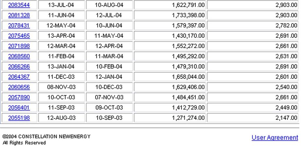
16 Electric Utility Load Data 16
Building Electrical System Overview
 Philip Mackey L/E Dr. Mistrick Holy Cross Hospital North Addition Silver Spring, MD 0/3/05 Building Electrical System Overview Executive Summary: The following report describes the existing emergency power
ELECTRICAL EXISTING CONDITIONS AND DESIGN ANALYSIS
 Executive Summary ELECTRICAL EXISTING CONDITIONS AND DESIGN ANALYSIS Sara Lappano Ltg./Elec. Corron Cultural Center Middletown, VA Faculty Advisor: Dr. Moeck 11.4.2002 As in the prior lighting technical
Chandler City Hall Chandler, Arizona
 Chandler City Hall Chandler, Arizona AE481W: Architectural Engineering Senior Thesis Wednesday October 27 th, 2010 Stephanie Romanias Lighting/Electrical Faculty Consultant Dr. Kevin Houser/Professor Dannerth
Technical II Report Electrical Systems
 Technical II Report Electrical Systems Kelly Chan Consultant: Prof T. Dannerth, P.E. Part A Drawings Drawings needed for single-line diagram EE1.01 title sheet (electrical drawings) EE2.09 penthouse/roof
Technical Report #2. Newseum and Freedom Forum Headquarters. Washington, D.C. Ryan Wise Lighting/Electrical Prof. Dannerth November 2, 2007
 Technical Report #2 Ryan Wise Lighting/Electrical Prof. Dannerth November 2, 2007 Newseum and Freedom Forum Headquarters Washington, D.C. Table of Contents Power Distribution Systems Executive Summary
Brown University Revised June 29, 2012 Facilities Design & Construction Standards SECTION ELECTRICAL DESIGN CRITERIA
 PART 1 - GENERAL 1.1 Background SECTION 26 00 10- ELECTRICAL DESIGN CRITERIA A. Brown University maintains it own campus electrical distribution system which serves the majority of the buildings and facilities
Lord Stirling Community School Electrical Systems Existing Conditions & Building Load Summary Technical Assingment#2 Due October 26, 2004
 Electrical Systems Existing Conditions & Building Load Summary Technical Assingment#2 Due October 26, 2004 Table of Content: Page 1 ~ Single Line Diagram 1 2 ~ Electrical System Narrative 2-3 3 ~ Lamp
Corbin Building. Technical Assignment 2. Matthew Trethaway Lighting/ Electrical AE 481W 10/26/2011 Advisor: Ted Dannerth
 Corbin Building Technical Assignment 2 Matthew Trethaway Lighting/ Electrical AE 481W 10/26/2011 Advisor: Ted Dannerth 10/26/2011 Technical Report II 1 Executive Summary The following report is an overview
Lindsay Frederick. Lighting + Electrical. Ron Dodson Faculty Advisor. Native American Cultural Center Arizona. Technical Report 2
 Lindsay Frederick Lighting + Electrical Ron Dodson Faculty Advisor Native American Cultural Center Arizona Technical Report 2 Native American Cultural Center Technical Report 2 p. 2 Executive Summary The
Electrical System (N) PANELBOARD "L1" VOLTAGE: 208/120 A, 3P :MAIN C/B PHASE: 3 A :BUSSING WIRE: 4 :MOUNTING
 PANELBOARD L1 VOLTAGE: 208/120 A, 3P :MAIN C/B PHASE: 3 A :BUSSING WIRE: 4 :MOUNTING") Electrical System After re-designing the lighting system for the children s computer, circulation and storytelling areas, the electrical system had to be redesigned as well. These are the new panel board
Electrical System After re-designing the lighting system for the children s computer, circulation and storytelling areas, the electrical system had to be redesigned as well. These are the new panel board
ELECTRICAL Seminar. B A L A Consulting Engineers, Inc. Edward J. Lynch, PE Vice President, Electrical Department Manager.
 B A L A Consulting Engineers, Inc. PECO Line 13.2kV Incoming Service No. 1 Utility/Generator Medium Voltage Switchgear PECO Line 13.2kV Incoming Service No. 2 Unit Substation ELECTRICAL Seminar HVAC Equip.
Technical Report 2: Electrical Systems Criteria and Existing Conditions
 Technical Report 2: Electrical Systems Criteria and Existing Conditions Princeton Theological Seminary Library Princeton, NJ Stephanie Deckard Lighting Electrical Faculty Advisor Dr. Kevin Houser 10/12/2012
Electrical Systems Existing Conditions and Building Load Summary Report
 The building was constructed a few years ago to act as both a Headquarters and to be a display of what the product they manufacture can accomplish when put to work. The building features both office and
Chang Liu Lighting + Electrical M.A.E./B.A.E. Integrated Degree. Technical Assignment 2 October 12, 2012 Faculty Consultants: Ron Dodson
 M.A.E./B.A.E. Integrated Degree Technical Assignment 2 October 12, 2012 Faculty Consultants: Ron Dodson Renzo Museum of American Art Executive Summary This report provides an analysis of the electrical
Technical Assignment #2 Electrical Systems Existing Conditions & Building Load Summary
 Technical Assignment #2 Electrical Systems Existing Conditions & Building Load Summary William H. Gates Hall Seattle, WA Katherine Jenkins Lighting/Electrical Option October 27, 2006 Faculty Advisor: Ted
Technical Report Two
 Technical Report Two Yale Sculpture Building Advisors: Ted Dannerth Richard Mistrick Date: October 31, 2006 Electrical Systems Existing Conditions and Building Load Summary Report Executive Summary: This
MID MICHIGAN COMMUNITY COLLEGE HARRISON CAMPUS Harrison, Michigan 2015 MASTER PLAN
 MID MICHIGAN COMMUNITY COLLEGE HARRISON CAMPUS Harrison, Michigan 2015 MASTER PLAN September 30, 2015 PBA Project No. 2015.0140.00 PETER BASSO ASSOCIATES INC. CONSULTING ENGINEERS 5145 LIVERNOIS ROAD,
DESIGN AND CONSTRUCTION STANDARDS GENERAL DESIGN GUIDELINES
 2.07 ELECTRICAL GENERAL DESIGN AND CONSTRUCTION STANDARDS GENERAL DESIGN GUIDELINES - 2.07 It is expected that the electrical design professional will conform to accepted good engineering design practices.
TONY ESPOSITO LIGHTING/ELECTRICAL TECHNICAL REPORT II SEPTEMBER 15, 2011 HUNTER S POINT SOUTH INTERMEDIATE SCHOOL AND HIGH SCHOOL QUEENS, NY
 LIGHTING/ELECTRICAL TECHNICAL REPORT II SEPTEMBER 15, 2011 HUNTER S POINT SOUTH INTERMEDIATE SCHOOL AND HIGH SCHOOL QUEENS, NY 1 1A. POWER DISTRIBUTION SYSTEMS a. EXECUTIVE SUMMARY b. SUMMARY DESCRIPTION
Element D Services Electrical
 PART 1 - GENERAL 1.01 OVERVIEW A. This Section includes design standards and requirements for electrical service and distribution. This is a design standard and is not intended to be used as a Specification.
Newark, Delaware Architectural Engineering Senior Thesis Portfolio. Electrical Analysis
 Electrical Analysis The AstroPower Headquarters building was constructed a few years ago to act as both a Headquarters and to be a display of what the product they manufacture can accomplish when put to
Electrical Systems Existing Conditions and Building Load Summary Broadway Plaza, Rochester, MN. Appendix A
 Appendix A Single Line Diagram Power Riser Diagram Dimming System Schematic Diagrams Dry-Type Transformer Schedule Primary Lamp and Ballast Table Mechanical Equipment Table Utility Rate Structure Breakdown
ELECTRIC SERVICE EVALUATIONS ELECTRICAL / BOILER REPLACEMENTS. Clarkstown Central School District. June Arch Proj. #
 ELECTRICAL ELECTRIC SERVICE EVALUATIONS / BOILER REPLACEMENTS Clarkstown Central School District June 2015 CSArch Arch Proj. # 151-1501.00 151 Table of Contents SECTION 1 Executive Summary... 1 SECTION
Ho-Chunk Gaming THUNDERBIRD ENGINEERING, INC. MILWAUKEE: (414) MADISON: (608)
 MADISON: (608)") Ho-Chunk Gaming POWER SYMBOLS X ELECTRICAL PANEL - REFER TO DRAWINGS FOR WIDTH AND PANEL SCHEDULES PANEL NAMING: XXP-#X: DENOTES PANEL FUNCTION: L = LIGHTING P = GENERAL POWER E = EMERGENCY S = OPTIONAL
Ho-Chunk Gaming POWER SYMBOLS X ELECTRICAL PANEL - REFER TO DRAWINGS FOR WIDTH AND PANEL SCHEDULES PANEL NAMING: XXP-#X: DENOTES PANEL FUNCTION: L = LIGHTING P = GENERAL POWER E = EMERGENCY S = OPTIONAL
Please refer to the drawing and notes for each particular plan view. Site Plan S1-1 Site Drawing. Electrical E1-1 Main Electrical Drawing
 The property that I discuss is an actual property that I helped to build. My position was as the Facility/Project Manager while the building was under construction. I worked very closely with the Senior
Computing Services Center
 Continuous Commissioning Report for the Computing Services Center Building #516 Submitted to: Utilities Energy Office Physical Plant Department Texas A&M University Prepared by: Energy Systems Laboratory
Electrical Design Guidelines Table of Contents
 C: Compliant Rev. 3 Dated June 13 11 NC: Non-Compliant NA: Not Applicable Page1 16.1 General 16.2 Single Line Diagrams 16.3 Electric Motor Equipment and Controls 16.4 Lighting 16.5 Emergency Lighting 16.6
NORTH CENTRAL MICHIGAN COLLEGE PETOSKEY CAMPUS. Facilities Conditions Assessment Mechanical And Electrical Petoskey, Michigan
 NORTH CENTRAL MICHIGAN COLLEGE PETOSKEY CAMPUS Facilities Conditions Assessment Mechanical And Electrical Petoskey, Michigan PBA Project No. 2014.0137.00 Prepared By: Wayne Kerbelis Terry Cleis September
ELECTRICAL SYSTEMS ASSESSMENT Hanover High School
 ELECTRICAL SYSTEMS ASSESSMENT Hanover High School ELECTRICAL DISTRIBUTION SYSTEM:?? The existing electrical service consists of an underground primary service originating at a utility pole on Cedar Street,
STATEWIDE CAREER/TECHNICAL EDUCATION COURSE ARTICULATION REVIEW MINUTES
 STATEWIDE CAREER/TECHNICAL EDUCATION COURSE ARTICULATION REVIEW MINUTES Articulation Agreement Identifier: ELT 118 (2005-1) Identifier is the postsecondary course prefix followed by Plan-of-Instruction
Technical Assignment 3 11/15/04. Executive Summary
 Executive Summary This report is an analysis of the existing systems within the Outreach Innovation Building in University Park, PA. One significant design criteria was a lower than average noise criteria
EADQUARTERS. Technical Report One. Stephanie Kunkel Mechanical Option
 EADQUARTERS 707 N. Calvert St. Technical Report One ASHRAE Standard 62.1 Ventilation ASHRAE Standard 90.1 Energy Design Stephanie Kunkel www.engr.psu.edu/ae/thesis/portfolios/2011/slk5061 Mechanical Option
Retrocommissioning Findings Summary: Building X #1 Priority: Major Comfort/Control Problems
 IMPORTANT NOTICE: This sample document is provided for instructional purposes only. CCC is not rendering advice concerning any commission project or practices. This document is neither approved nor intended
1080 Marina Village Parkway, Suite 501 Alameda, CA (510) Fax (510) HVAC DESIGN INTENT
 Fax (510) HVAC DESIGN INTENT") Taylor Engineering 1080 Marina Village Parkway, Suite 501 Alameda, CA 94501-1142 (510) 749-9135 Fax (510) 749-9136 LLC HVAC DESIGN INTENT PART 1 - GENERAL 1.1 Overview A. The project consists of a 3-story
Taylor Engineering 1080 Marina Village Parkway, Suite 501 Alameda, CA 94501-1142 (510) 749-9135 Fax (510) 749-9136 LLC HVAC DESIGN INTENT PART 1 - GENERAL 1.1 Overview A. The project consists of a 3-story
ELECTRICAL/MECHANICAL INFRARED INSPECTION REPORT. The Corporate Facility 2001 Freedom Way United City, USA
 ELECTRICAL/MECHANICAL INFRARED INSPECTION REPORT for The Corporate Facility 2001 Freedom Way United City, USA January 01, 2012 Job Number: 1111-12 TABLE OF CONTENTS I - Introduction to the Report Explains
Dates of Construction Construction Start 2/28/1999 Date of Completion 4/2000 Occupancy 5/2000
 Executive Summary The Milton S. Hershey Medical Center Academic Support Building is located on The Pennsylvania State University's campus in Hershey, PA. The building is owned by The Pennsylvania State
NYC Department of Education
 NYC Department of Education Building Assessment Survey 2017-2018 Asset: P.S. 135 - QUEENS, 207-11 89TH AVENUE, New York, 11427 Inspection Id Inspection Type Time In Last Edited EE : Electrical 2018-03-20
PANELBOARDS & BUILDING DISTRIBUTION
 262416 PANELBOARDS & BUILDING DISTRIBUTION PART 1 GENERAL 1.01 SUMMARY A. Section Includes: 1. Distribution panelboards 2. Power panelboards B. Related Sections: 1.02 POLICY 1. CU Standard 260500, Basic
Technical Report #3 Mechanical Systems Existing Conditions Evaluation
 Mechanical Option Technical Report #3 Technical Report #3 Mechanical Systems Existing Conditions Evaluation Instructor: Dr. Bahnfleth 11.15.04 Building Sponsor: CCG Facilities Integration Table of Contents
LIGHT LEVEL REQUIREMENTS MINIMUM ACCEPTABLE FOOT CANDLES
 LIGHT LEVEL REQUIREMENTS LOCATION Classrooms and instrumental areas- Study Halls, Lecture Rooms, Art Rooms, Offices, Libraries, Conference Rooms, Work Rooms, Shops, Laboratories and Secondary School Cafeterias.
NYC Department of Education
 NYC Department of Education Building Assessment Survey 2017-2018 Asset: P.S. 56 - STATEN ISLAND, 250 KRAMER AVE., New York, 10309 Inspection Id Inspection Type Time In Last Edited EE : Electrical 2017-10-20
UltraLITE Model ELU Centralized Emergency Lighting Inverter 4.2 KW- 5 KW
 12/23/16 Rev 9 UltraLITE Model ELU General Specification 4.2 KW to 5 KW UltraLITE Model ELU Centralized Emergency Lighting Inverter 4.2 KW- 5 KW 1.0 General General Specification This specification describes
Senior Thesis Centre Community Hospital East Wing Addition - Proposal Keith Beidel Mechanical Option 12/05/02 1
 Table of Contents Page Number(s) Executive Summary 2 Project Background 3 Proposed Depth Alternatives 4 Proposed Depth Redesign 5-7 Justification of Proposed Depth Redesign 8 Proposed Breath Redesign 9
Currently, all electrical upgrades would be voluntary, but there are situations in which upgrades would be required.
 Executive Summary The current electrical system is functional but requires some understanding in order to avoid overloading circuits. Certain outlets can be used for space heaters while others cannot and
Technical Assignment 3
 0 David H. Koch Institute for Integrative Cancer Research Senior Capstone Mechanical Option Technical Assignment 3 Mechanical Systems and Existing Conditions Report David H. Koch Institute for Integrative
Old Jail HVAC Replacement Feasibility Report
 Old Jail HVAC Replacement Feasibility Report Madera, CA Prepared by Kitchell for the County of Madera, California Job No. 6168A3 Executive Summary On October 21, 2016, Kitchell conducted a Feasibility
Infrared Electrical Inspection Report
 Infared Inspections * Switchgear Testing & Cleaning Vibration Analysis * Arc Flash Hazard Analysis & Training SAMPLE REPORT Company Address City, ST 12345 Inspected on: 9/29/2016 Infrared Electrical Inspection
FIRE ALARM: BY OTHERS, IF REQUIRED.
 x x x x x x OS LIGHTING S FLUORESCENT LIGHT FIXTURE, SEE LIGHT FIXTURE SCHEDULE FOR SIZE AND MOUNTING. CAPITAL LETTER DENOTES TYPE, LOWER CASE LETTER DENOTES SWITCH LEG. FLUORESCENT STRIP LIGHT FIXTURE,
Division 26 ELECTRICAL TABLE OF CONTENTS
 Division 26 ELECTRICAL TABLE OF CONTENTS 26 1000 GENERAL... 33 A. CODE... 3 B. RELATED SECTIONS... 3 C. ABBREVIATIONS... 3 D. DEFINITIONS... 3 E. DRAWING REQUIREMENTS... 3 F. EQUIPMENT SERVICE ACCESS AND
ENGINE GENERATORS AND ACCESSORIES
 ENGINE GENERATORS AND ACCESSORIES GENERAL INFORMATION 1.1 This section applies to engine generators and accessories. DESIGN REQUIREMENTS 2.1 The Engineer of Record will consult with the University s Engineering
Mechanical Technical Report 1. ASHRAE Standard 62.1 Ventilation Compliance Evaluation
 Mechanical Technical Report 1 Standard 62.1 Ventilation Compliance Evaluation Lutheran Theological Seminary at Philadelphia The New Learning Center Prepared For: William P. Bahnfleth, Ph.D., P.E. Department
Rocky Mountain Chapter IAEI Annual Meeting Northglenn, CO March 18-19, 2004
 Rocky Mountain Chapter IAEI Annual Meeting Northglenn, CO March 18-19, 2004 1. A 2 PVC conduit was installed in the ground prior to setting a factory manufactured home on the foundation. The required service
FIRE ALARM: BY OTHERS, IF REQUIRED.
 x x x x x x OS LIGHTING S FLUORESCENT LIGHT FIXTURE, SEE LIGHT FIXTURE SCHEDULE FOR SIZE AND MOUNTING. FLUORESCENT STRIP LIGHT FIXTURE, SEE LIGHT FIXTURE SCHEDULE FOR SIZE AND MOUNTING. WALL BRACKET FLUORESCENT
Michigan State University DESIGN GUIDELINES. ELECTRICAL DESIGN Page 1 TABLE OF CONTENTS 1
 Page 1 TABLE OF CONTENTS 1 ELECTRICAL 2 Summary Sustainability Electrical Distribution Lighting Detection and Alarm Communication Systems Lightning Protection Clock Systems Access Control Housekeeping
Electrical Inspection Service & Distribution
 0911 Distribution Panels & Switchgear Equipment, conduit, feeders, and grounding 480 Volt Switchboard: This switchboard contains the utility meter and two main, service, circuit breakers. One circuit breaker
Cook - Wissahickon Elementary School
 Cook - Wissahickon Elementary School 201 E. Salaignac St., Philadelphia, PA 19128 HVAC Replacement Project Scope Determination Report May 10, 2018 Prepared by: G.P. Lamina, Jr., P.E., MBA School District
AIR-CONDITIONING SYSTEMS AND APPLICATIONS. Abdullah Nuhait Ph D. King Saud University
 AIR-CONDITIONING SYSTEMS AND APPLICATIONS Abdullah Nuhait Ph D. King Saud University AIR-CONDITIONING SYSTEMS Earliest air conditioning system used only for heating (winter) Provided heated air for comfort
TABLE LIGHTING POWER DENSITIES FOR BUILDING EXTERIORS ASHRAE Uncovered Parking Areas. Building Grounds. Walkways 10 feet wide or greater
 TABLE 9.4.5 LIGHTING POWER DENSITIES FOR BUILDING EXTERIORS ASHRAE 90.1 Uncovered Parking Areas Parking Lots and drives Building Grounds Walkways less that 10 feet wide Walkways 10 feet wide or greater
Spectron LSN (Life Safety Network) Suggested Specifications
 Suggested Specifications") 1. General 1.1 Scope A Dual-Lite Spectron LSN (Life Safety Network) Series Inverter System shall be furnished to provide a reliable source of power, and shall operate during a utility line deficiency without
1. General 1.1 Scope A Dual-Lite Spectron LSN (Life Safety Network) Series Inverter System shall be furnished to provide a reliable source of power, and shall operate during a utility line deficiency without
NYC Department of Education
 NYC Department of Education Building Assessment Survey 2017-2018 Asset: P.S. 314 - BROOKLYN, 330 59 STREET, New York, 11220 Inspection Id Inspection Type Time In Last Edited EE : Electrical 2018-04-23
Building Division 201 SE 3 rd STREET (Second Floor) OCALA, FL Phone: (352) BUILDING CODE GUIDELINES FOR ELECTRICAL INSPECTIONS
 OCALA, FL Phone: (352) BUILDING CODE GUIDELINES FOR ELECTRICAL INSPECTIONS") BUILDING CODE GUIDELINES FOR ELECTRICAL INSPECTIONS Building Code compliance is the obligation of design professionals and/or contractors. Plan Review and Inspection Guidelines are intended to be used
BUILDING CODE GUIDELINES FOR ELECTRICAL INSPECTIONS Building Code compliance is the obligation of design professionals and/or contractors. Plan Review and Inspection Guidelines are intended to be used
CHAPTER 20 SERVICE EQUIPMENT
 SERVICE EQUIPMENT CHAPTER 20 SERVICE EQUIPMENT Service equipment includes service cabinets and the equipment and materials necessary for installation. 20.1 Signal Service Cabinet For MnDOT traffic control
BASIC ELECTRICAL ENGINEERING FOR CE
 EE24 BASIC ELECTRICAL ENGINEERING FOR CE LECTURE NO. B-2 Basic Electrical Code Provisions Codes/Standards/Organizations PEC Philippine Electrical Code NEC National Electrical Code IEEE - Institute of Electrical
Related Sections: TBD. Effective Date: January 1, 2016
 Description: The purpose of the section is to highlight the current applicable UMCP Design Standards for the design, selection and, installation of lighting fixtures within buildings. Related Sections:
NEC Study Guide CORRECT: C NEC (A)(1)
(1)") 1 According to the NEC, the maximum distance from the point of entrance to the building that the water pipe may be used as a grounding electrode interconnect is: A. 3' B. 4' C. 5' D. 6' CORRECT: C NEC
1 According to the NEC, the maximum distance from the point of entrance to the building that the water pipe may be used as a grounding electrode interconnect is: A. 3' B. 4' C. 5' D. 6' CORRECT: C NEC
Terminal. Las Vegas, NV. Technical
 McCarran International port Terminal 3 Technical Assignment 3 Mechanical System Existing Conditions Evaluation December 3, 2007 Prepared By: Faculty Advisor: Dr. William Bahnfleth, Ph.D., P..E. Table of
UNIVERSITY OF MISSOURI Heating Ventilating and Air-Conditioning (HVAC) 2016 Q1
 2016 Q1") GENERAL: This section provides general standards for overall sizing and design of Heating, Ventilating, and Air Conditioning (HVAC) systems. Other sections contain specific standards for each system per
GENERAL: This section provides general standards for overall sizing and design of Heating, Ventilating, and Air Conditioning (HVAC) systems. Other sections contain specific standards for each system per
NYC Department of Education
 NYC Department of Education Building Assessment Survey 2017-2018 Asset: DIV. COMPUTER INFO-DATA CENTER-K, 2 METROTECH CENTER, New York, 11211 Inspection Id Inspection Type Time In Last Edited EE : Electrical
Guide Specification Model CTG Automatic Transfer Switch
 Guide Specification Model CTG Automatic Transfer Switch PART 1 GENERAL 1.1 Scope A. It is the intent of this specification to secure a transfer switch that has been prototype tested, factory built, production
Andrea Borowski The Pennsylvania State University University Park, PA November 11, 2002 Consultant: Dr. Bahnfleth Technical Assignment M-3
 Existing System Evaluation Executive Summary The MBNA Career Services Center is a 44,000 square foot, 4-story office type building at Penn State University, University Park Campus. The building is located
Architectural Engineering Senior Thesis Mechanical System Redesign
 Saint Joseph Medical Center Architectural Engineering Senior Thesis Mechanical System Redesign Chris Nicolais Building Description Existing Mechanical System Proposed Redesign Alternative Option Emergency
Mechanical System Redesign. Dedicated Outdoor Air System. Design Criteria
 Mechanical System Redesign Dedicated Outdoor Air System Design Criteria The outdoor air conditions used were for Philadelphia, Pennsylvania IAP at a 0.4% occurrence. The supply air conditions were developed
Technical Report 2: Electrical Systems Existing Conditions and Building Load Summary Report. 100% Submission. Sherrerd Hall, Princeton University, NJ
 Technical Report 2: Electrical Systems Existing Conditions and Building Load Summary Report 100% Submission Sherrerd Hall, Princeton University, NJ Faculty Consultant: Ted Dannerth 4 November 2009 Table
4. OVERVIEW OF MECHANICAL SYSTEM
 4. OVERVIEW OF MECHANICAL SYSTEM The 87,000 SF SLCC is served by six (6) Trane M-Series Climate Changer Air Handing Units (AHUs). Each unit serves a distinct zone within the facility that is unique in
ELECTRICAL POWER SYSTEMS
 Scope The various Codes applicable to the University's electrical power system are mainly based upon a model of a single utility service, connected to a single premise. The University s electrical system,
NEC Requirements for Standby Power Systems. New England Building Officials Education Association Annual Conference October 5, 2015
 NEC Requirements for Standby Power Systems New England Building Officials Education Association Annual Conference October 5, 2015 Emergency & Standby Power Systems Alternative power sources are utilized
Title: YALE OFFICE OF FACILITIES PROCEDURE MANUAL Chapter: 01 - Yale Design Standard Division: Electrical Standards
 Change History Date Description of Change Pages / Sections Modified Change Approver Initials 8/1/17 Updated section on Manufacturers 3 1. 6/15/16 Updated division section from 16120 to 26 05 00, - mgl44
GPS 140 NEC Requirements for Generators. Professional Development Seminar Series NEC Requirements for Generators
 GPS 140 NEC Requirements for Generators WHAT YOU WILL LEARN NEC requirements for on-site power generation. Recent events have created increased interest in standby power This module organizes NEC requirements
GARCIA GALUSKA DESOUSA Consulting Engineers
 L#57297 /Page 1/July 21, 2017 ELECTRICAL SYSTEMS NARRATIVE REPORT The following is the Electrical Systems narrative, which defines the scope of work and capacities of the Power and Lighting systems, as
MEP CONDITION ASSESSMENT
 MAINE EAST MEP CONDITION ASSESSMENT MAINE EAST HIGH SCHOOL This report section includes an overview of the existing mechanical cooling and heating systems serving Maine East High School. The sections will
Proposed Mechanical, Plumbing, and Electrical Systems For the LEDYARD POLICE DEPARTMENT LEDYARD, CT
 DESIGN ASSOCIATES INC MECH/ELEC DESIGN & CONSULTING 422 Highland Ave, Cheshire, CT. 06410 (203) 271-3787, fax (203) 271-2886 Proposed Mechanical, Plumbing, and Electrical Systems For the LEDYARD POLICE
elite Model ELN Centralized Emergency Lighting Inverter Systems 550 W to 1.5 KW Systems
 5/25/16 rev 6 elite Model ELN General Specification 550 W to 1.5 KW elite Model ELN Centralized Emergency Lighting Inverter Systems 550 W to 1.5 KW Systems 1.0 General General Specification This specification
Job Name Control Systems Description Date
 Job Name Control Systems Description Date Project Overview The project is a describe the building and its major HVAC systems (e.g. three-story office building, served by a rooftop unit VAV system ). In
PART 1. Executive Summary. The Frederick College of Cardiology
 Executive Summary This report will summarize the electrical system of the Frederick College of Cardiology. First, an estimation of the possible building electrical loads will be performed. The actual loads
A. Section includes distribution panelboards and lighting and appliance branch-circuit panelboards.
 SECTION 262416 - PANELBOARDS PART 1 - GENERAL 1.1 SUMMARY A. Section includes distribution panelboards and lighting and appliance branch-circuit panelboards. 1.2 PERFORMANCE REQUIREMENTS A. Seismic Performance:
ELECTRICAL CURRICULA OUTLINE CORE CURRICULUM 2015
 ELECTRICAL CURRICULA OUTLINE CORE CURRICULUM 2015 Basic Safety (Construction Site Safety Orientation) (12.5 Hours) (Module ID 00101-15) Presents basic jobsite safety information to prepare workers for
Renovate MCRC Facilities Great Lakes, IL
 6. ENGINEERING SYSTEMS REQUIREMENTS D50 ELECTRICAL SYSTEM DESCRIPTION The electrical repair work includes the design and construction of the electrical distribution system for the B3200 Marine Corps Reserve
ITC 2000 HEATING CONTROL CABINET. Installation & Operation Manual
 ITC 2000 HEATING CONTROL CABINET Installation & Operation Manual VTI, Incorporated 24 McMillan Way Newark, DE 19713 Phone (302) 738 0500 FAX (302) 738 6594 Revision Level 0.03 Manual No. 90003314 June,
SCHOOL DISTRICT PALM BEACH COUNTY BUILDING DEPARTMENT PLAN REVIEW CHECK LIST -- ELECTRICAL
 SCHOOL DISTRICT PALM BEACH COUNTY BUILDING DEPARTMENT PLAN REVIEW CHECK LIST -- ELECTRICAL 3300 SUMMIT BOULEVARD WEST PALM BEACH, FLORIDA 33406 TEL (561) 688-7687 FAX (561) 688-7654 http://www.palmbeach.k12.fl.us/fm/bd/index.htm
CITY OF LOS ANGELES LARUCP ELECTRICAL PLAN CHECK LIST
 CITY OF LOS ANGELES LARUCP ELECTRICAL PLAN CHECK LIST Plan Check No. Plan Check Expiration Date Job Address: Square Footage Use Zone Fire Zone Occ. Group Type of Construction No. of Stories Applicant Phone
SECTION PANELBOARDS Painting Wire and Cable Overcurrent Protective Devices.
 SECTION 16470 PANELBOARDS PART 1 GENERAL 1.01 SUMMARY A. Related Sections: 1. 09900 - Painting. 2. 16120 - Wire and Cable. 3. 16475 - Overcurrent Protective Devices. 1.02 SYSTEM DESCRIPTION A. Performance
WIRING AND PROTECTION
 5997ch02.qxd_mg_cc 4/6/05 12:42 PM Page 5 2 WIRING AND PROTECTION (Excerpts from Chapter 2) 210.1 Scope ARTICLE 210 BRANCH CIRCUITS I. General Provisions Article 210 applies to all branch circuits except
CARRIER edesign SUITE NEWS. Modeling 100% OA Constant Volume Air Systems. Volume 6, Issue 1. Page 1 Modeling 100% OA Constant Volume Air Systems
 Volume 6, Issue 1 CARRIER edesign SUITE NEWS Modeling 100% OA Constant Volume Air Systems This article provides an overview of how to model a stand-alone constant air volume (CAV) 100% OA system in HAP.
CONNECTICUT. Downloaded
 Housekeeping/Laundry/Maintenance J. Laundry. CONNECTICUT Downloaded 01.15.11 (1) This service, if provided, shall be used exclusively for laundry and shall be remote from resident and food service areas,
Student Services & Classroom Addition. A. Section includes distribution panelboards and lighting and appliance branch-circuit panelboards.
 SECTION 262416 - PANELBOARDS PART 1 - GENERAL 1.1 SUMMARY A. Section includes distribution panelboards and lighting and appliance branch-circuit panelboards. 1.2 PERFORMANCE REQUIREMENTS A. Seismic Performance:
The Creative and Performing Arts High School (CAPA) Pittsburgh, PA 11/11/2002 Andrew Tech Mechanical Option Prof. S. A. Mumma
 Pittsburgh, PA 11/11/2002 Andrew Tech Mechanical Option Prof. S. A. Mumma") Objectives and Requirements For the Creative and Performing Arts High School (CAPA), the main objective of the mechanical design is to provide an energy efficient system that is easily maintainable and
Objectives and Requirements For the Creative and Performing Arts High School (CAPA), the main objective of the mechanical design is to provide an energy efficient system that is easily maintainable and
MECHANICAL, ELECTRICAL, PLUMBING, AND FIRE PROTECTION CONDITIONS FACILITIES MASTER PLAN MAY
 MECHANICAL, ELECTRICAL, PLUMBING, AND FIRE PROTECTION CONDITIONS FACILITIES MASTER PLAN MAY 2018 57 MECHANICAL ASSESSMENT MECHANICAL ASSESSMENT This report section includes an overview of the existing
.4 Do complete installation in accordance with latest Electrical Bulletins of the local inspection authority.
 Fitness Facility Addition Page 1 1.1 CODES AND STANDARDS.1 Do complete installation in accordance with the latest edition of the CSA C22.1 as amended by the latest editions of the National Building Code
NYC Department of Education
 Building Assessment Survey 2017-2018 Asset: NEW SCH FOR ARTS AND SCIENCE - X, 965 LONGWOOD AVENUE, New York, 10459 Inspection Id Inspection Type Time In Last Edited EE : Electrical 2017-12-01 8:13 AM 2017-12-01
INITIAL ELECTRICAL SAFETY ASSESSMENT - EXPANSION
 INITIAL ELECTRICAL SAFETY ASSESSMENT - EXPANSION Yunusco (BD) Ltd(Formerly Shore To Shore Textiles Ltd.) Plot# 224-233, Adamjee EPZ, Shiddirgonj, Narayangonj Siddirgonj The Alliance for Bangladesh Worker