NORTH CENTRAL MICHIGAN COLLEGE PETOSKEY CAMPUS. Facilities Conditions Assessment Mechanical And Electrical Petoskey, Michigan
|
|
|
- Primrose Campbell
- 5 years ago
- Views:
Transcription


1 NORTH CENTRAL MICHIGAN COLLEGE PETOSKEY CAMPUS Facilities Conditions Assessment Mechanical And Electrical Petoskey, Michigan PBA Project No Prepared By: Wayne Kerbelis Terry Cleis September 2014 PETER BASSO ASSOCIATES INC CONSULTING ENGINEERS TROY, MICHIGAN NEUMANN SMITH ARCHITECTS SOUTHFIELD, MICHIGAN
2 TABLE OF CONTENTS Tab 2014 Five Year Master Plan Summary Campus Overview 1 Campus Map Campus Mechanical Equipment Description Campus Electrical System Description Electrical Building Component Life Expectancy Schedule Proposed Campus Chilled Water Loop Site Plan Proposed Campus Chilled Water Loop Schematic Administration Building 2 Mechanical Equipment Description Mechanical Building Component Life Expectancy Schedule Electrical Equipment Description Electrical Building Component Life Expectancy Schedule Heating Plant 3 Mechanical Equipment Description Mechanical Building Component Life Expectancy Schedule Electrical Equipment Description Electrical Building Component Life Expectancy Schedule Library 4 Mechanical Equipment Description Mechanical Building Component Life Expectancy Schedule Electrical Equipment Description Electrical Building Component Life Expectancy Schedule Maintenance Building 5 Mechanical Equipment Description Mechanical Building Component Life Expectancy Schedule Electrical Equipment Description Electrical Building Component Life Expectancy Schedule Residence Hall 6 Mechanical Equipment Description Mechanical Building Component Life Expectancy Schedule Electrical Equipment Description Electrical Building Component Life Expectancy Schedule Student and Community Resource Center 7 Mechanical Equipment Description Mechanical Building Component Life Expectancy Schedule Electrical Equipment Description
3 Electrical Building Component Life Expectancy Schedule Student Cafeteria/Conference Center 8 Mechanical Equipment Description Mechanical Building Component Life Expectancy Schedule Electrical Equipment Description Electrical Building Component Life Expectancy Schedule Technology Building 9 Mechanical Equipment Description Mechanical Building Component Life Expectancy Schedule Electrical Equipment Description Electrical Building Component Life Expectancy Schedule
4
5
6
7
8
9 CAMPUS MECHANICAL EQUIPMENT DESCRIPTIONS General Campus Description North Central Michigan College s Petoskey Campus was established in 1962 with construction of the Heating Plant and Chemistry Building. NCMC Petoskey Campus has undergone many renovations and additions from 1962 to present including mechanical and electrical systems, infrastructure upgrades, building renovations, and additions. Campus Existing Facilities: Campus Hot Water Heating System - The campus heating hot water system (boilers) located in the Heating Plant was upgraded in 2010 and serves the heating requirements for all the contiguous Petoskey Campus Buildings with the exception of the Early Childhood education Building. Heating hot water is generated by eight high efficiency condensing gas fired heating hot water boilers. Heating hot water distribution system is piped in a primary loop arrangement. Two variable flow primary pumps (one operates continuously while the other is stand-by) circulate heating hot water through the primary loop through the campus tunnel system from the boilers to each of the building(s) heating equipment. Building heating equipment utilize 2-way and 3-way control valves controlled to maintain space temperatures. Heating hot water system is controlled by the campus energy management and control system. Campus Cooling System Currently there are currently six electric chillers on campus two are serving the administration and classroom building, two serves the Student center Building, one serves the Student and Community Resource Building and one chiller serves the Libraries. The Technology and Maintenance Building is cooled from individual direct expansion unit with remote condenser units that are located just outside of each of the buildings. Findings: The heating hot water piping system is routed in two branch runs from the heating plant. One branch is routed in tunnel and feeds the Administration/Classroom Building, Library, Student Center Cafeteria & Conference Center, Residence Hall and Student & Community Resource Center. The other hot water heating branch is routed in the tunnel and feeds the Maintenance building, Technology Building and Health Education & Science Center. As a result of this configuration the campus is experiencing flow and pumping issues. In addition, extra hot water heating pump energy is required to meet the building demands and future campus expansion is limited by hot water heating flow distribution. The campus cooling system is currently configured where each campus building has its own individual cooling system. If a chiller fails for any reason cooling is lost to the CM-1
10 building (no back up). In addition, the individual building chillers do not modulate and are cycled to maintain cooling set points as a result the cooling system is less efficient and produced additional wear to the equipment. Recommendations: 1. Provide additional tunnel and hot water heating piping to form a campus loop. The campus loop will provide improved flow to each building, more efficient hot water distribution and expand capacity in the campus heating system. 2. Provide a de-centralized chilled water campus loop. If the tunnel is expanded in a campus loop the individual campus building chillers can be connected together to common campus cooling system. The benefits of a campus de-centralized chilled water loop system are as follows: Potential electrical cooling energy saving 20%-30%. Provides redundancy in campus cooling systems. o If a campus chiller fails another chiller connected to loop will provide cooling. o No cooling down time to conditioning campus buildings. Extends life expectancy of chilled water equipment. Reduced maintenance. Improves cooling controllability throughout campus. Installs infrastructure for consolidating campus chillers in future. Provided economical equipment replacement as existing chillers age. 3. As building equipment ages the calibration, comfort control and energy efficiencies diminish. To keep the campus buildings operating at the peak, each building should be retro- commissioned every five years. CM-2
11 CAMPUS ELECTRICAL SYSTEMS DESCRIPTIONS General Campus Description North Central Michigan College s Petoskey Campus was established in 1962 with construction of the Heating Plant and Chemistry Building. NCMC Petoskey Campus has undergone many renovations and additions from 1962 to present including mechanical and electrical systems, infrastructure upgrades, building renovations, and additions. Campus Power: The existing 12,470V primary distribution system was upgrade in The system currently consists of a long radial arm with taps to feed the major buildings. Some of the smaller buildings are fed from systems in the larger buildings. Completion of the tunnel system will close the loop around campus. When this is achieved, the primary system should be reworked to create a primary loop. This will provide flexibility in how each building is fed, and will allow buildings to be isolated from the rest of the campus while still keeping rest of campus powered. There is a mixture of voltages in the buildings. Some buildings contain both 480/277V and 208/120V systems, while other buildings are entirely 208/120V. Emergency Power: Currently there only two generators on Campus and these units are primarily dedicated to backing up telecommunication systems. The emergency egress lighting in all of the buildings consist of emergency fixtures with dedicated battery units. This type of system requires monthly testing of batteries, and ongoing maintenance to insure that all of the units are operating properly. Adding generation capabilities could all many of these fixtures to be removed and could utilize existing fixtures for emergency egress functions. This would replace battery testing, maintenance, and replacement, with generator maintenance and testing. Additional benefits often include better egress lighting coverage, and the ability to provide backup power to selected loads like sump pumps to prevent flooding or boilers to prevent freezing. CE-1
12 Site Several site lighting issues have been identified. There are existing concrete poles that are failing and need to be replaced. There are planned changes to the ring road and to the parking lots that will require modifications to the site lighting. Occupancy sensor and LED technologies could also provide energy cost savings. The existing art lighting is also in need of an upgrade that could include energy cost savings. CE-2
13
14
15
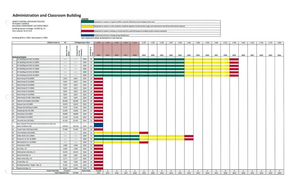
16 ADMINISTRATION / CLASSROOM BUILDING MECHANICAL EQUIPMENT DESCRIPTIONS General Building Description The Administration and Classroom Building is located between the Library and Heating Plant. The Administration and Classroom Building was constructed in 1965 and underwent a major renovation of HVAC equipment and alterations to room layout in Building mechanical equipment is currently served by campus heating hot water system. The building is a two story building that consists of approximately 52,000 square feet. Classrooms and administrative offices are located in the Administration and Classroom Building. Building Cooling System Two Air cooled chillers that are located in the basement of the building serving AHU-10, AHU-11, AHU-14, AHU-17, AHU-18, AHU-19, and Unit Ventilators which were upgraded in 2004 and serves the cooling requirements for the Administration and Classroom Building. Chilled Water piping is piped to each of the units located in the plenum space of on each of the floors of the building and serves the AHU s located in the penthouse. Air Handler Unit AHU-10, located in Mechanical Room 59 of the Administration and Classroom Building; is a constant volume, mixed air system installed in The system consists of outside air dampers, relief louver with relief air dampers, filters, hot water heating coil with circulating pump for freeze protection and chilled water cooling coil. The AHU-10 serves the East portion of the building spaces on the Lower Level of the Administration and Classroom Building and supplies air to the spaces thru individual tempering coils and diffusers Air Handler Unit AHU-11, located in Mechanical Room 56 of the Administration and Classroom Building; is a constant volume, mixed air system installed in The system consists of an outside air damper, relief louver with relief air dampers, filters, hot water heating coil with circulating pump for freeze protection and chilled water cooling coil. The AHU-11 serves the West portion of the building spaces on the Lower Level of the Administration and Classroom Building and supplies air to the spaces after passing thru individual tempering coils and diffusers Air Handler Unit AHU-14, located in Mechanical Room of the Administration and Classroom Building; is a constant volume, mixed air system installed in The system consists of an outside air damper, relief louver with relief air dampers, filters, hot water heating coil with circulating pump for freeze protection, chilled water cooling coil. The AHU-14 serves the Art/ Ceramics Classrooms on the Lower Level of the Administration and Classroom Building and supplies air to the spaces thru individual tempering coils and diffusers. AM-1
17 Air Handler Unit AHU-17, located in the penthouse; is a constant volume, mixed air system installed in The system consists of an outside air damper, relief louver with relief air dampers, filters, hot water heating coil with circulating pump for freeze protection, chilled water cooling coil. The AHU-17 serves the Nursing 27 on the Lower Level of the Administration and Classroom Building and supplies air to the space with diffusers. Air Handler Unit AHU-18, located in the penthouse; is a constant volume, mixed air system installed in The system consists of an outside air damper, relief louver with relief air dampers, filters, hot water heating coil with circulating pump for freeze protection, chilled water cooling coil. The AHU-18 serves the East portion of the building spaces on the Main Level of the Administration and Classroom Building and supplies air to the spaces after passing thru individual terminal units and to the space with diffusers. Air Handler Unit AHU-19, located in the penthouse; is a constant volume, mixed air system installed in The system consists of an outside air damper, relief louver with relief air dampers, filters, hot water heating coil with circulating pump for freeze protection, chilled water cooling coil. The AHU-19 serves Lecture 122 of the building space on the Main Level of the Administration and Classroom Building and supplies air to the space with diffusers. Unit Ventilators located in each of the classrooms are constant air volume, mixed air systems installed in Each system consists of a multi speed air volume integral outside air, hot water heating coil, chilled water coil and a multi speed air volume supply air fan. The vertical unit ventilators serve the classrooms through its diffuser integral with the cabinet. Unit ventilators are controlled by the original campus DDC control system. Exhaust Fan EF-100 is a constant volume exhaust systems with motorized backdraft dampers. EF-100 located in the tunnel, installed in 1965 serves tunnel. Exhaust Fan EF-101 is a constant volume exhaust systems with motorized backdraft dampers. EF-101 located in the electrical room, installed in 1965 serves electrical room. Exhaust Fan EF-120 is a constant volume exhaust systems with motorized backdraft dampers. EF-120 located in the tunnel, installed in 1965 serves men s and women s toilet. Exhaust Fan EF-267 is a constant volume exhaust systems with motorized backdraft dampers. EF-267 located in the penthouse, installed in 1965 serves men s and women s toilet. Exhaust Fan (Penthouse Exhaust Fan) is a constant volume exhaust systems with motorized backdraft dampers. Penthouse exhaust fan located in the penthouse, installed in 1965 serves penthouse. AM-2
18 Plumbing Fixtures are located in the art spaces, bathrooms and janitors closet in the building. The fixtures in the building consist of Lav s, Double bowl sink, Multi-person sink, Service Sink, Drinking fountains, Water closets, and Urinals. These fixtures were installed in 1965 and have served the building since. AM-3
19
20 ADMINISTRATION/ CLASSROOM BUILDING ELECTRICAL EQUIPMENT DESCRIPTIONS General Building Description The Administration/ Classroom Building are located on the North side of campus near the Atkins Street parking lot. The Administration/ Classroom Building was constructed in 1965 and is a two story building that consists of approximately 52,000 square feet of space. Administration/ Classroom Building consists of classrooms, offices, and specialty classrooms (example: art rooms). POWER: The primary power enters the building from the tunnel system. The primary equipment is located in the main electrical room located on the west end of the lower level of the building. This room contains primary distribution equipment, including a primary switches and primary transformer (T4). Most of this equipment appears to be newer and in good condition. The building electrical distribution system consists mainly of branch circuit panelboard scattered around the building. This equipment is 208/120V. There is a mixture of new and older equipment. Most of the branch circuit distribution equipment appears to be the original building equipment. Many of these panelboards were manufactured by Federal Pacific. Federal Pacific went out of business many years ago, so replacement breakers and parts are difficult or impossible to obtain. If these panel are indeed from the original construction, they are surpassed their expected life expectancy and should be scheduled for replacement. There appeared to be electric heat in the Stairwells. Alternate heating systems could be explored for these areas. LIGHTING: Our understanding is that approximately 90% of the linear fluorescent lamps and their associated ballasts on campus have been changed from T12 to T8. It appears that most of the fixtures have been converted. Most of the lighting in the building is fluorescent with some type of prismatic acrylic lens. Many of these fixtures appear to be quite old and probably from the original construction. Most of the fixtures appear to contain their original prismatic lenses, and these lenses have started to yellow. Most of the light fixtures are surface mounted on the existing lay in ceilings. New fixtures and/or lenses could provide additional light and better color in many spaces. New fixtures could also provide energy savings. AE-1
21 It appears that a large portion of the lighting control consists of manual switch control. Current energy codes call for some sort of automatic lighting control. There are opportunities in this building to add lighting controls for energy code compliance. This could come in the form of occupancy sensors and would also result in energy savings and potential utility rebates. PBA was told that in some areas occupancy sensors were installed but later removed due to complaints about how they operated. A properly designed system using newer technology occupancy should be able to be installed and operate properly. There are a few opportunities in this building to provide controls for daylight harvesting. These should be explored for potential energy savings. There is an occupancy sensor for lighting control in the main electrical room. This should be replaced with a standard toggle switch. Code does not allow automatic lighting controls in these types of rooms. EMERGENCY SYSTEMS: There is no generator for power to support emergency egress lighting in this building. Some battery EXIT signs and were observed. Proper emergency light levels along paths should be verified. Monthly testing of all local battery lighting units should be documented and reviewed. AUXILIARY SYSTEMS: The existing fire alarm system consists of horn and strobe notification devices. These devices are mounted throughout the building. Many of these are ceiling mounted. Some smoke detection devices were noted during the tour of the building, however they were not observed throughout the entire building. With a horn based fire alarm system, there is currently no means of making announcements or mass notification of building tenants. The existing voice and data systems are located in closets. The cabling appears to be properly installed and protected. There are existing ceiling mounted WAP devices for wireless connectivity located throughout the building. There is a telecom rack located in a caged area in the penthouse. This should be reviewed to insure that this space meets the temperature requirements and provides a proper environment for this equipment. AE-2
22
23 HEATING PLANT MECHANICAL EQUIPMENT DESCRIPTIONS General Building Description The Heating Plant is located between the Administration and Classroom Building and Maintenance Building. The Heating Plant was constructed in 1965 and underwent a major renovation of mechanical equipment in The building is a single story building that consists of approximately 2,300 square feet. Boiler Room and Electrical room are located in the Heating Plant. Building Cooling System Two Air cooled condenser units that are located on the outside of the building serving the split system in the energy management office and the blower coil unit serving the electrical room which were upgraded in 2004 and serves the cooling requirements for these rooms. Refrigerant piping is piped to each of the units located in the plenum space of on each of the rooms of the building. Blower Coil Unit BCU-1, located in Electrical Room of the Heating Plant; is a constant volume system installed in The system consists of outside air dampers, relief louver with relief air dampers, filters, hot water heating coil with circulating pump for freeze protection, Dx cooling coil, and a constant volume supply fan with discharge damper for supply air volume control. The BCU-1 serves the Electrical room of the building space of the Heating Plant and supplies air to the space. BCU-1 is controlled by a combination of temperature controls and the campus DDC control system. Split system Air conditioner Unit, located in Energy management office of the Heating Plant; is an Air conditioner system installed in 2004 originally from the administration and classroom building. The system consists of a Dx cooling coil, and a constant volume supply fan with discharge damper for supply air volume control. The split system serves the Energy management office of the building space of the Heating Plant and provides cooling to the space. Split system is controlled by a combination of temperature controls and the campus DDC control system. HM-1
24
25 HEATING PLANT ELECTRICAL EQUIPMENT DESCRIPTIONS General Building Description The Heating Plant is located on the Northeast corner of campus next to the Maintenance Building. The Heating Plant was constructed in 1973 and is a single story building that consists primarily of mechanical equipment. There is a small room on the side of the building that contains some primary electrical equipment and some primary and secondary distribution equipment. POWER: The main power enters the building from the adjacent primary electrical room. This building is fed from the primary transformer T1 and then through the 300kVA low voltage transformer T2, located in the primary electrical room. The equipment is all newer and in good condition. The building electrical distribution system consists of branch circuit panelboards. The entire system in this building is 208/120V. There is storage in front of much of the equipment that needs to be cleared. The code required existing for the main electrical room should be reviewed. It appears that there is not sufficient clearance in front of the primary equipment. This needs to be reviewed and addressed. LIGHTING: Our understanding is that approximately 90% of the linear fluorescent lamps and their associated ballasts on campus have been changed from T12 to T8. It appears that most of the fixtures have been converted. Most of the lighting is in satisfactory condition. However, the light coverage could be improved and also made more efficient. EMERGENCY SYSTEMS: There is no generator set up to supply emergency power to support emergency egress lighting in this building. Some battery EXIT signs and both ceiling and wall mounted Emergency Battery Units (EBUs or Bug Eyes ) were noted throughout the facility. Proper emergency light levels along paths should be verified. Monthly testing of all local battery lighting units should be documented and reviewed. HE-1
26 AUXILIARY SYSTEMS: The fire alarm system consists of horn and strobe notification devices. These devices are mounted throughout the building. Many of these are ceiling mounted. With a horn based fire alarm system, there is currently no means of making announcements or mass notification of building tenants. HE-2
27
28 LIBRARY MECHANICAL EQUIPMENT DESCRIPTIONS General Building Description The Library is located on the East side of campus between the Administration/ Classroom Building and Health Education and Student Center. The Library was constructed in 1984 and is a single story building that consists of approximately 19,550 square feet. Building is served from the campus hot water heating system. Library consists of Conference rooms, offices, kitchen, computer room and the Library. Building Cooling System Air cooled chiller that is located in the outside of the building serving AHU-1, AHU-2 which are original to the building and serves the cooling requirements for the Library. Chilled Water piping is piped to each of the units located in the penthouse of the building. Air Handling Unit AHU-1, located in the Mechanical Penthouse of the Library; is a constant volume, mixed air system installed in The system consists of an outside air damper, gravity relief hood with relief air dampers, filters, hot water heating coil with circulating pump for freeze protection, chilled water cooling coil. The AHU-1 serves the library and office space of the building and supplies air to the spaces after passing thru the room specific variable volume box with heating coil. Air Handler Unit AHU-2 located in the Mechanical Penthouse of the Library; is a constant volume, mixed air system installed in The system consists of an outside air damper, gravity relief hood with relief air dampers, filters, hot water heating coil with circulating pump for freeze protection, chilled water cooling coil. The AHU-2 serves the conference rooms, office space and kitchen area of the building and supplies air to the spaces after passing thru the room specific variable volume box with heating coil. Exhaust Fans EF-1 is a constant volume exhaust systems with motorized backdraft dampers. EF-1 located on the roof, installed in 1984 serves Men s and Women s toilet rooms. Plumbing Fixtures are located in the kitchen space bathrooms and janitors closet in the building. The fixtures in the building consist of Lav s, Triple bowl Kitchen sink, Service Sink, Drinking fountains, Water closets, and Urinals. These fixtures were installed in 1984 and have served the building since. LM-1
29 Findings: The majority of the buildings HVAC systems have well reached their service life as defined by the American Society of Heating, Refrigeration and Air-Conditioning Engineers (ASHRAE). Refer to building component life expectancy graphs for itemized building equipment list. Recommendations: It is recommended that the Library HVAC have exceeded their service life and should be replaced. In addition, replacement of HVAC is recommended based on reasons of potential failure, general obsolescence, reduce reliability, excessive maintenance cost and change in system requirements due to such influences as building characteristics, and energy usage considerations. LM-2
30
31 LIBRARY ELECTRICAL EQUIPMENT DESCRIPTIONS General Building Description The Library is located on the East side of campus between the Administration/ Classroom Building and Health Education and Student Center. The Library was constructed in 1984 and is a single story building that consists of approximately 19,550 square feet. Library consists of Conference rooms, offices, kitchen, computer room and the Library. POWER: The primary power enters the building from the tunnel system. The primary equipment is located in penthouse of the building in a combined mechanical/electrical room. This room contains primary distribution equipment, including a primary switches and primary transformer (T6). This equipment appears to be a mixture of newer equipment and older equipment. The older appears that it may be from the original construction. If that is the case, the original equipment has reached its anticipated life expectancy and should be scheduled for replacement. The building electrical distribution system consists mainly of branch circuit panelboards scattered around the south corner of the building. This equipment is 208/120V. There is a mixture of new and older equipment. Most of the branch circuit distribution equipment appears to be the original building equipment. These panelboards were manufactured by Square D. If these panel are indeed from the original construction, they have reached their life expectancy and should be scheduled for replacement. LIGHTING: Our understanding is that approximately 90% of the linear fluorescent lamps and their associated ballasts on campus have been changed from T12 to T8. It appears that most of the fixtures have been converted. Because of the varied usage of the different spaces in this building, there is a mixture of various types of light fixtures. Some of the light fixtures appear to be in satisfactory condition. The original design light levels are unknown, but the fixtures should be replaced to use less energy and provide better lighting,. This is particularly important in the library area. There are ballasts located in the penthouse for the lighting in the building. These could be removed if newer, more efficient lighting is installed. It appears that a large portion of the lighting control consists of manual switch control. Current energy codes call for some sort of automatic lighting control. There are opportunities in this building to add lighting controls for energy code compliance. LE-1
32 This could come in the form of occupancy sensors and would also result in energy savings and potential utility rebates. There may also be the potential for a timer controlled lighting control in the book storage area. EMERGENCY SYSTEMS: There is an abandoned emergency central battery and inverter system in this building. This system should be removed. There is no generator for power to support emergency egress lighting in this building. Some battery EXIT signs and Emergency Battery Units (EBUs or Bug Eyes) were observed. Proper emergency light levels along paths should be verified. Monthly testing of all local battery lighting units should be documented and reviewed. AUXILIARY SYSTEMS: The fire alarm system consists of horn and strobe notification devices. These devices are mounted throughout the building. Many of these are ceiling mounted. Some smoke detection devices were noted during the tour of the building, however they were not observed throughout the entire building. With a horn based fire alarm system, there is currently no means of making announcements or mass notification of building tenants. The existing voice and data systems are located in closets. The cabling appears to be properly installed and protected. There are existing ceiling mounted WAP devices for wireless connectivity located throughout the building. LE-2
33
34 MAINTENANCE BUILDING MECHANICAL EQUIPMENT DESCRIPTIONS General Building Description The Maintenance Building is located near the Heating Plant and Technology Building. The Maintenance Building was constructed in The building is a single story building that consists of approximately 3,400 square feet and is served hot water heating by the campus heating plant. Equipment Storage and Maintenance and Women s / Men s Toilets are located in the Maintenance Building. Air Handler Unit AHU-1, located in the plenum space of the Technology Building; is a constant volume, mixed air system installed in The system consists of an outside air damper, gravity relief hood with relief air dampers, filters, hot water heating coil with circulating pump for freeze protection. The AHU-1 serves the Toilet rooms and the south portion of the Maintenance Area space with diffusers. Air Handler Unit AHU-2, located in the plenum space of the Technology Building; is a constant volume, mixed air system installed in The system consists of an outside air damper, gravity relief hood with relief air dampers, filters, hot water heating coil with circulating pump for freeze protection. The AHU-2 serves the Maintenance Area space with diffusers. Exhaust Fans EF-1 is a constant volume exhaust systems with motorized backdraft dampers. EF-1 located on the roof, installed in 1973 serves Men s and Women s toilet rooms. Exhaust Fans EF-2 is a constant volume exhaust systems with motorized backdraft dampers. EF-2 located inline of the duct work that serves the hood in the maintenance area. Unit Heaters - are in place for heating the Maintenance area and Storage room. Convectors - are located in each of the Toilet areas to heat each of the spaces Plumbing Fixtures are located in the bathrooms and janitors closet in the building. The fixtures in the building consist of Lav s, Service Sink, Drinking fountains, Water closets, and Urinals. These fixtures were installed in 1973 and have served the building since. MM-1
35
36 MAINTENANCE BUILDING AND ELECTRICAL EQUIPMENT DESCRIPTIONS General Building Description The Maintenance Building is located on the Northeast corner of campus next to the Heating Plant. The Maintenance Building was constructed in 1973 and is a single story building with a small mezzanine that consists primarily of a garage and a shop. POWER: The main power enters the building from the nearby primary electrical room. This building is fed with a 400A feeder from the switchboard in the adjacent Heating Plant. The building electrical distribution system consists of branch circuit panelboards. The entire system in this building is 208/120V. LIGHTING: Our understanding is that approximately 90% of the linear fluorescent lamps and their associated ballasts on campus have been changed from T12 to T8. It appears that most of the fixtures have been converted. Most of the lighting is in satisfactory condition. EMERGENCY SYSTEMS: There is no generator set up to supply emergency power to support emergency egress lighting in this building. Some battery EXIT signs and both ceiling and wall mounted Emergency Battery Units (EBUs or Bug Eyes ) were noted throughout the facility. Proper emergency light levels along paths should be verified. Monthly testing of all local battery lighting units should be documented and reviewed. AUXILIARY SYSTEMS: The fire alarm system consists of horn and strobe notification devices. These devices are mounted throughout the building. Many of these are ceiling mounted. With a horn based fire alarm system, there is currently no means of making announcements or mass notification of building tenants. ME-1
37
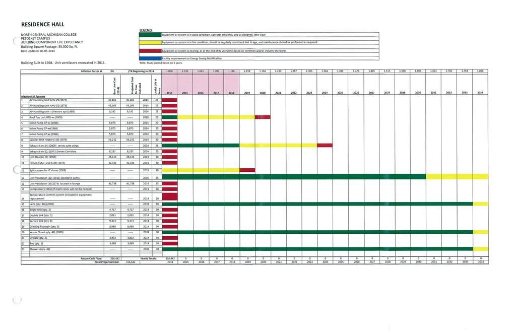
38 RESIDENCE HALL BUILDING MECHANICAL EQUIPMENT DESCRIPTIONS General Building Description The Residence Hall is located on the Southwest side of campus just south of the Student Center Cafeteria. The Residence Hall was constructed in 1973 and is a four story building that consists of approximately 35,000 square feet. The Residents Hall consists of Student Dorms. Air Handler Unit AHU-29, located in Mechanical Room 607 of the Residence Hall; is a constant volume, mixed air system installed in The system consists of outside air dampers, relief louver with relief air dampers, filters, hot water heating coil with circulating pump for freeze protection. The AHU-29 serves the West portion of the building spaces on the Basement Level of the Residence Hall Building and supplies air to the spaces thru individual tempering coils and diffusers. Air Handler Unit AHU-32, located in Mechanical Room of the Residence Hall; is a constant volume, mixed air system installed in The system consists of outside air dampers, relief louver with relief air dampers, filters, hot water heating coil with circulating pump for freeze protection. The AHU-32 serves the South portion of the building spaces on the Basement Level of the Residence Hall Building and supplies air to the spaces thru individual tempering coils and diffusers. Roof Top Unit RTU-xx, located on the roof of the student Lounge area of the building of the Residence Hall; is a constant volume, mixed air system installed in The system consists of outside air dampers, relief louver with relief air dampers, filters, hot water heating coil with circulating pump for freeze protection. The RTU-xx serves the North portion of the building spaces on the First Floor Level of the Residence Hall Building and supplies air to the spaces thru individual tempering coils and diffusers. Exhaust Fan EF-xx is a constant volume exhaust systems with motorized backdraft dampers. Exhaust Fan EF-xx is a constant volume exhaust systems with motorized backdraft dampers. Exhaust Fan EF-xx is a constant volume exhaust systems with motorized backdraft dampers. Exhaust Fan EF-xx is a constant volume exhaust systems with motorized backdraft dampers. RM-1
39 Plumbing Fixtures are located in the kitchen spaces, bathrooms and janitors closet in the building. The fixtures in the building consist of Lav s, Single bowl sink, Double bowl sink, Service Sink, Drinking fountains, Water closets, Showers, and Urinals. These fixtures were installed in 1973 and have served the building since. RM-2
40
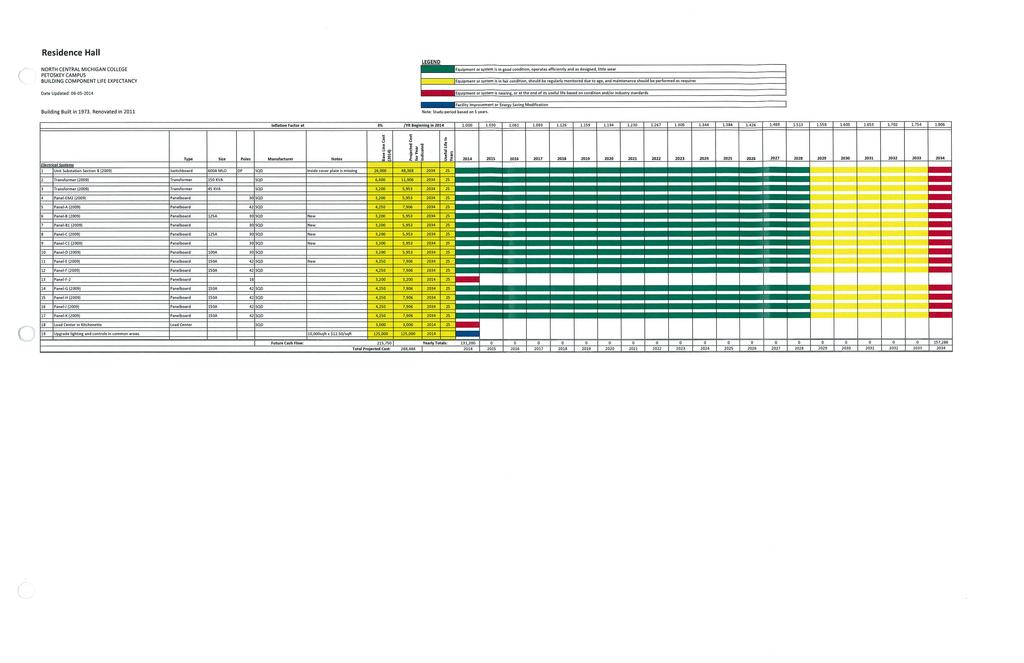
41 RESIDENCE HALL ELECTRICAL EQUIPMENT DESCRIPTIONS General Building Description The Residence Hall is located on the Southwest side of campus just south of the Student Center Cafeteria. The Residence Hall was constructed in 1973 and is a four story building that consists of approximately 35,000 square feet. The Residents Hall consists of Student Dorms. POWER: The main power enters the building through the tunnel system. The main equipment is located in the basement of the building. This building is fed from the primary equipment located in the adjacent SCRC building. The power for this building originates from a 150kVA 480V-208/120V transformer located in the basement Main Electrical Room. The main electrical equipment appears to be newer and in good condition. The building electrical distribution system consists mainly of branch circuit panelboards scattered throughout the building. Many of the panelboards have been replaced with newer Square D panelboards, but the balance of the electrical distribution system consists of older equipment, possibly from the original construction. Any equipment from the original construction has surpassed its anticipated life expectancy and should be scheduled for replacement. There is storage in front of electrical equipment in several locations in the building. These areas need to be kept clear. LIGHTING: Our understanding is that approximately 90% of the linear fluorescent lamps and their associated ballasts on campus have been changed from T12 to T8. It appears that most of the fixtures have been converted to T8 of have been retrofit with newer technology lamps like LED. The light levels and distribution should be improved. New, more efficient light fixtures should be explored. Many of the light fixtures are showing signs of age. Newer lighting could provide aesthetic and quality improvements as well as save energy. Most of the observed lighting control consists of toggle switches. Current energy codes call for some sort of automatic lighting control. There are several areas in this building where daylight harvesting opportunities are present. RE-1
42 The lighting in the basement should be all be replaced to save energy and to provide better better quality and quantity of lighting. EMERGENCY SYSTEMS: There is no generator set up to supply emergency power to support emergency egress lighting in this building. Some battery EXIT signs and both ceiling and wall mounted Emergency Battery Units (EBUs or Bug Eyes ) were noted throughout the facility. Proper emergency light levels along paths should be verified. Monthly testing of all local battery lighting units should be documented and reviewed. AUXILIARY SYSTEMS: This building contains a main telecommunication hub in the basement. The service provider fiber optic systems enter the campus through this room. This room is backed up by generator power. The fire alarm system consists of horn and strobe notification devices. These devices are mounted throughout the building. Many of these are ceiling mounted. The building contains a sprinkler system. With a horn based fire alarm system, there is currently no means of making announcements or mass notification of building tenants. The existing voice and data systems are located in closets. The cabling appears to be properly installed and protected. It appears that there are existing wall and ceiling mounted WAP devices for wireless connectivity located throughout the building. RE-2
43
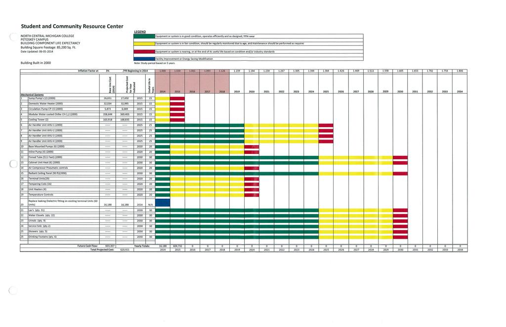
44 STUDENT AND COMMUNITY RESOURCE CENTER MECHANICAL EQUIPMENT DESCRIPTIONS General Building Description The Student and Community Resource Center is located between the Student Center and Health Education & Science Center. The SCRC was constructed in 19xx and underwent a major renovation of HVAC equipment in The building is a two story building that consists of approximately 85,200 square feet. The SCRC consists of conference rooms, offices, a large open multipurpose space, and a bookstore. Building Cooling System Two Air cooled chillers that are located in the basement of the building and in the second floor mechanical room serving AHU-1, AHU-2, AHU-3, AHU-4 which were upgraded in 2000 and serves the cooling requirements for the SCRC. Chilled Water piping is piped to each of the units located in the Mechanical space of the building. Air Handler Unit AHU-1, located in Mechanical Room 216 of the Student and Community Resource Center; is a constant volume, mixed air system installed in The system consists of outside air dampers, relief louver with relief air dampers, filters, hot water heating coil with circulating pump for freeze protection, chilled water cooling coil. The AHU-1 serves the multipurpose portion of the building spaces of the Student and Community Resource Center and supplies air to the spaces after passing thru individual tempering coil and diffusers. Air Handler Unit AHU-2, located in Mechanical Room 216 of the Student and Community Resource Center; is a constant volume, mixed air system installed in The system consists of an outside air damper, relief louver with relief air dampers, filters, hot water heating coil with circulating pump for freeze protection, chilled water cooling coil. The AHU-2 serves the Weight training and Aerobics room and first floor locker rooms the of the building spaces on the upper & lower level of the Student and Community Resource Center and supplies air to the spaces after passing thru individual tempering coil and diffusers. Air Handler Unit AHU-3, located in Mechanical Room 3 in the basement of the Student and Community Resource Center; is a constant volume, mixed air system installed in The system consists of an outside air damper, relief louver with relief air dampers, filters, hot water heating coil with circulating pump for freeze protection, chilled water cooling coil. The AHU-3 serves the tutor center and office space on the lower level of the Student and Community Resource Center and supplies air to the spaces after passing thru individual tempering coil and diffusers. SCRCM-1
45 Air Handler Unit AHU-4, located in the Mechanical Room 3; is a constant volume, mixed air system installed in The system consists of an outside air damper, relief louver with relief air dampers, filters, hot water heating coil with circulating pump for freeze protection, chilled water cooling coil. The AHU-4 serves the college store and office space of the building spaces on the lower Level of the Student and Community Resource Center and supplies air to the spaces after passing thru zone specific terminal units and to the space with diffusers. Plumbing Fixtures are located in the Locker rooms, bathrooms and janitors closet in the building. The fixtures in the building consist of Lav s, showers, Service Sink, Drinking fountains, Water closets, and Urinals. These fixtures were installed in 19xx and have served the building since. SCRCM-2
46
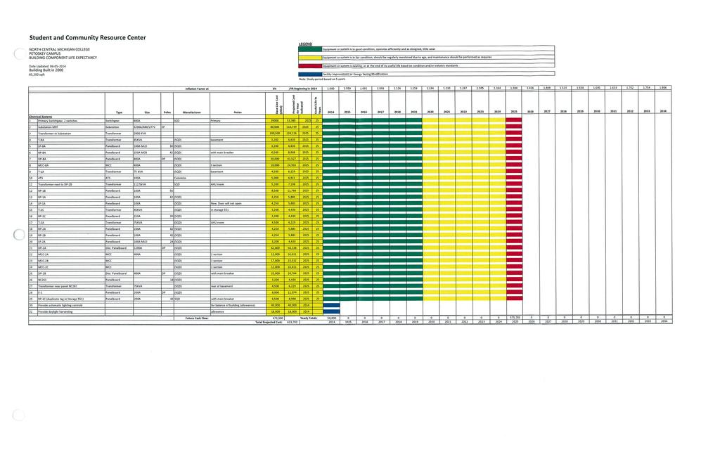
47 STUDENT AND COMMUNITY RESOURCE CENTER ELECTRICAL EQUIPMENT DESCRIPTIONS General Building Description The Student and Community Resource Center (SCRC) is located on the South side of campus adjacent to the Cafeteria and next to the Heath Education and Science Center. The SCRC was constructed in 2000 and is a two story building that consists of approximately 85,200 square feet. The SCRC consists of conference rooms, offices, a large open multipurpose space, and a bookstore. POWER: The primary power enters the building from the tunnel system. The primary equipment is located in main electrical room in the basement of the building. This room contains primary distribution equipment, including a primary switches and unit substation containing a primary transformer (T9). There are other large portions of the electrical distribution system located in the tunnels and in various Mech/Elect Rooms throughout the facility. This equipment appears to be a mixture of newer equipment and older equipment. The building electrical distribution system consists mainly of branch circuit panelboards scattered throughout the building. There is a mixture of both 480/277V and 208/120V branch circuit distribution equipment. There is a mixture of new and older equipment, including some panelboards manufactured by Federal Pacific, who has been out of business for many years. There are also some newer panelboards that were manufactured by Square D. LIGHTING: Our understanding is that approximately 90% of the linear fluorescent lamps and their associated ballasts on campus have been changed from T12 to T8. It appears that most of the fixtures have been converted or are newer energy efficient fixtures. Because of the varied usage of the different spaces in this building, there is a mixture of various types of light fixtures. The light fixtures appear to be in satisfactory condition and are likely providing light base on their original design intentions. The lighting control systems varied throughout the facility. Current energy codes call for some sort of automatic lighting control. There are several opportunities for daylight harvesting in this facility. This would save energy and eliminate artificial lighting trying to compete with natural light. SCRCE-1
48 There is existing automatic occupancy sensor lighting control in the main electrical room. Code does not allow for automatic lighting control in this type of space. This should be replaced with a manual control system. EMERGENCY SYSTEMS: There is no generator set up to supply emergency power to support emergency egress lighting in this building. Some battery EXIT signs and both ceiling and wall mounted Emergency Battery Units (EBUs or Bug Eyes ) were noted throughout the facility. Proper emergency light levels along paths should be verified. Monthly testing of all local battery lighting units should be documented and reviewed. AUXILIARY SYSTEMS: The fire alarm system consists of horn and strobe notification devices. These devices are mounted throughout the building. Many of these are ceiling mounted. Some smoke detection devices were noted during the tour of the building, however they were not observed throughout the entire building. With a horn based fire alarm system, there is currently no means of making announcements or mass notification of building tenants. The existing voice and data systems are located in closets. The cabling appears to be properly installed and protected. There are existing ceiling mounted WAP devices for wireless connectivity located throughout the building. SCRCE-2
49
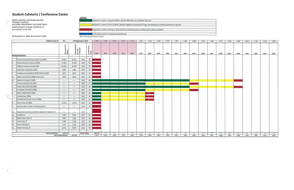
50 STUDENT CAFETERIA / CONFERENCE CENTER BUILDING MECHANICAL EQUIPMENT DESCRIPTIONS General Building Description The Student Cafeteria / Conference Building is located between the Maintenance Building and Health Education and Science Center. The Student Center Building was constructed in 1968 and underwent a major renovation of HVAC equipment and alterations to room layout in The building is a two story building that consists of approximately 18,500 square feet. Offices, conferences, and Cafeteria are located in the Student Center Building. Building Cooling System Air cooled chiller that is located in the first floor mechanical room of the building serving AHU-5 which were upgraded in 2000 and serves the cooling requirements for the Student Center Building. Chilled Water piping is piped to the unit located in the mechanical space on the first floor of the building. Air Handler Unit AHU-1, located in the Mechanical space of the Student Center Building; is a constant volume, mixed air system installed in The system consists of an outside air damper, gravity relief hood with relief air dampers, filters, hot water heating coil with circulating pump for freeze protection, and Chilled water cooling coil. The AHU-1 serves the building spaces of the Student Center Building and supplies air to the spaces after passing thru room specific terminal unit and diffusers. Roof Top Unit RTU-1 thru 4, located on the roof of the Student Center Building; is a constant volume, mixed air system installed in 19xx. The system consists of an outside air damper, gravity relief hood with relief air dampers, filters, hot water heating coil with circulating pump for freeze protection, Dx cooling coil. The RTU-1 thru 4 serves the cafeteria and kitchen of the Student Center Building to the space with diffusers. Exhaust Fans EF-109 is a constant volume exhaust systems with motorized backdraft dampers. EF-1 located in the mechanical space on first floor, installed in 19xx serves Mechanical Space. Plumbing Fixtures are located in the Kitchen, bathrooms and janitors closet in the building. The fixtures in the building consist of Lav s, Double Sinks, showers, Service Sink, Water closets, and Urinals. These fixtures were installed in 19xx and have served the building since. SCM-1
51
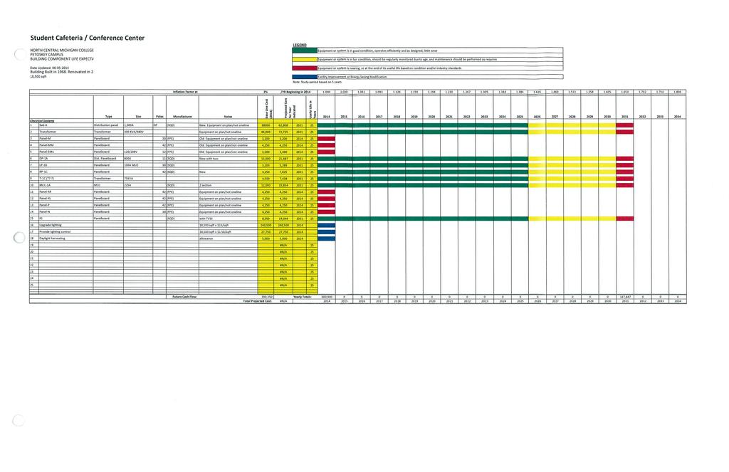
52 STUDENT CAFETERIA / CONFERENCE CENTER BUILDING ELECTRICAL EQUIPMENT DESCRIPTIONS General Building Description The Student Cafeteria / Conference Center are located on the South side of campus adjacent to the SCRC and just north of Residence Hall. The SCC was constructed in 1968 and is a two story building that consists of approximately 18,500 square feet. The SCC consists of cafeteria, kitchen, dining area, meeting rooms, and offices. POWER: The main power enters the building from the tunnel system. The main equipment is located in the basement of the building in a space that is part of the tunnel system. This building is fed from the primary equipment located in the adjacent SCRC building. Most of the power for this building originates from a 300kVA 480V-208/120V transformer located in the tunnel space. There are other large portions of the electrical distribution system located in the tunnels and in various Mech/Elect Rooms throughout the facility. This equipment appears to be a mixture of newer equipment and older equipment. The building electrical distribution system consists mainly of branch circuit panelboards scattered throughout the building. Some of the panelboards are located in the tunnel system. There is a mixture of new and older equipment, including some panelboards manufactured by Federal Pacific, who has been out of business for many years. There are also some newer panelboards that were manufactured by Square D. LIGHTING: Our understanding is that approximately 90% of the linear fluorescent lamps and their associated ballasts on campus have been changed from T12 to T8. It appears that most of the fixtures have been converted. Because of the varied usage of the different spaces in this building, there is a mixture of various types of light fixtures. Some of the light fixtures are showing signs of age. Most of the observed lighting control consists of toggle switches. In the dining area, these switches are grouped together in a large bank of 12 switches. Current energy codes call for some sort of automatic lighting control. With the large existing window openings, there are several areas in this building where daylight harvesting opportunities are present. SCE-1
53 EMERGENCY SYSTEMS: There is no generator set up to supply emergency power to support emergency egress lighting in this building. Some battery EXIT signs and both ceiling and wall mounted Emergency Battery Units (EBUs or Bug Eyes ) were noted throughout the facility. Proper emergency light levels along paths should be verified. Monthly testing of all local battery lighting units should be documented and reviewed. AUXILIARY SYSTEMS: The fire alarm system consists of horn and strobe notification devices. These devices are mounted throughout the building. Many of these are ceiling mounted. Some smoke detection devices were noted during the tour of the building, however they were not observed throughout the entire building. With a horn based fire alarm system, there is currently no means of making announcements or mass notification of building tenants. The existing voice and data systems are located in closets. The cabling appears to be properly installed and protected. It appears that there are existing wall and ceiling mounted WAP devices for wireless connectivity located throughout the building. SCE-2
54
MID MICHIGAN COMMUNITY COLLEGE HARRISON CAMPUS Harrison, Michigan 2015 MASTER PLAN
 MID MICHIGAN COMMUNITY COLLEGE HARRISON CAMPUS Harrison, Michigan 2015 MASTER PLAN September 30, 2015 PBA Project No. 2015.0140.00 PETER BASSO ASSOCIATES INC. CONSULTING ENGINEERS 5145 LIVERNOIS ROAD,
State College Area School District High School South Building EXISTING CONDITIONS ASSESSMENT
 State College Area School District High School South Building Prepared by CenterPoint Engineering 08 February 2013 FACILITY ASSESSMENT SUMMARY PHYSICAL PLANT General HVAC This report is a snapshot of the
Appendix B. Facilities Assessment Report
 Mile Lane Army Reserve Center Redevelopment Plan September 2008 Appendix B Facilities Assessment Report RKG Associates, Inc. Mile Lane Army Reserve Base Middletown, CT MEP System Evaluation For RKG Associates
HOLUM EDUCATION CENTER. Architectural. January 13, 2014 DeForest Area School District
 HOLUM EDUCATION CENTER Architectural The existing building has approximately 41,823 square feet and sets on a lot about 4.14 acres in size. Parking lots are located along the east and west sides of the
PLATTEVILLE MIDDLE SCHOOL
 Architectural The building has aluminum clad wood awning windows in combination with aluminum fixed glass units. They appear to be exterior glazed with insulated glazing. See photo 2. Platteville Middle
Florence High School / Middle School Page 1 of 3 Florence, WI
 Florence High School / Middle School Page 1 of 3 Florence, WI Plumbing Systems Review: The following report is the result of a site visit by Tim Kehoe of Muermann Engineering, LLC that occurred on October
Brown University Revised June 29, 2012 Facilities Design & Construction Standards SECTION ELECTRICAL DESIGN CRITERIA
 PART 1 - GENERAL 1.1 Background SECTION 26 00 10- ELECTRICAL DESIGN CRITERIA A. Brown University maintains it own campus electrical distribution system which serves the majority of the buildings and facilities
MOUNT PLEASANT MIDDLE SCHOOL HVAC. M-01 Heating Plant: M-02 Heating & Ventilating Systems: Livingston School District Mount Pleasant Middle School
 MOUNT PLEASANT MIDDLE SCHOOL HVAC M-01 Heating Plant: The existing boilers have recently been upgraded. (3) steam boilers (8660 mbh each) manufactured by Weil- McLain have been installed. Newer hot water
State College Area School District High School North Building EXISTING CONDITIONS ASSESSMENT
 State College Area School District High School North Building Prepared by CenterPoint Engineering 08 February 2013 FACILITY ASSESSMENT SUMMARY PHYSICAL PLANT General HVAC This report is a snapshot of the
S AGE E NGINEERING A SSOCIATES, LLP
 S AGE E NGINEERING A SSOCIATES, LLP 1211 Western Avenue Albany, NY (518) 453 6091 F (518) 453 6092 Kingston Library Mechanical and Electrical Systems Field Report Date of Visits: Mechanical - September
1080 Marina Village Parkway, Suite 501 Alameda, CA (510) Fax (510) HVAC DESIGN INTENT
 Fax (510) HVAC DESIGN INTENT") Taylor Engineering 1080 Marina Village Parkway, Suite 501 Alameda, CA 94501-1142 (510) 749-9135 Fax (510) 749-9136 LLC HVAC DESIGN INTENT PART 1 - GENERAL 1.1 Overview A. The project consists of a 3-story
Taylor Engineering 1080 Marina Village Parkway, Suite 501 Alameda, CA 94501-1142 (510) 749-9135 Fax (510) 749-9136 LLC HVAC DESIGN INTENT PART 1 - GENERAL 1.1 Overview A. The project consists of a 3-story
Sprinkler: The building does not have a fire protection system installed. MECHANICAL / PLUMBING / SPRINKLER SYSTEMS RECOMMENDATIONS
 EXISTING MECHANICAL CONDITIONS SUMMARY The items listed below are based on our site visit on Nov 10, 2016. Our review is based on current conditions and anticipated future use of these building. In the
Computing Services Center
 Continuous Commissioning Report for the Computing Services Center Building #516 Submitted to: Utilities Energy Office Physical Plant Department Texas A&M University Prepared by: Energy Systems Laboratory
DIVISION 23 - HVAC HVAC
 DIVISION 23-23 00 00 PART 1 - GENERAL 1.01 GENERAL CRITERIA A. The heating system typical set point shall be 70 F inside. 1. The winter outdoor design temperature for most systems shall be -6 F. 2. The
Corbin Building. Technical Assignment 2. Matthew Trethaway Lighting/ Electrical AE 481W 10/26/2011 Advisor: Ted Dannerth
 Corbin Building Technical Assignment 2 Matthew Trethaway Lighting/ Electrical AE 481W 10/26/2011 Advisor: Ted Dannerth 10/26/2011 Technical Report II 1 Executive Summary The following report is an overview
Currently, all electrical upgrades would be voluntary, but there are situations in which upgrades would be required.
 Executive Summary The current electrical system is functional but requires some understanding in order to avoid overloading circuits. Certain outlets can be used for space heaters while others cannot and
Executive Summary. CNBC Global Headquarters Christine Cajilig
 Executive Summary This report contains an analysis and description of the existing electrical distribution of the including the distribution type, emergency power, uninterruptible power system, over current
Madeira City Schools Madeira, Ohio. HVAC Assessment. December 2011 (Revised February 2012)
") Madeira City Schools Madeira, Ohio HVAC Assessment December 2011 (Revised February 2012) Prepared by: CMTA Engineering Consultants, Inc. 10411 Meeting Street Prospect, KY 40059 www.cmtaegrs.com (502) 326-3085
Madeira City Schools Madeira, Ohio HVAC Assessment December 2011 (Revised February 2012) Prepared by: CMTA Engineering Consultants, Inc. 10411 Meeting Street Prospect, KY 40059 www.cmtaegrs.com (502) 326-3085
Facility Condition Assessment Summary Report. British Columbia Institute of Technology NE6 - Plumbing and Pipefit Building
 Facility Condition Assessment Summary Report British Columbia Institute of Technology NE6 - Plumbing and Pipefit Building Submitted by: VFA Canada Corp. Burnaby Centre 4211 Kingsway Burnaby, BC V5H 1Z6
Agustin Lara Elementary Academy
 Facility Assessment Summary This report summarizes the findings of a facility assessment completed on the date noted in the document footer below. Assessors rate each facility feature and system by visual
Calmeca Academy of Fine Arts and Dual Language
 Facility Assessment Summary This report summarizes the findings of a facility assessment completed on the date noted in the document footer below. Assessors rate each facility feature and system by visual
UNIVERSITY OF MISSOURI Heating Ventilating and Air-Conditioning (HVAC) 2016 Q1
 2016 Q1") GENERAL: This section provides general standards for overall sizing and design of Heating, Ventilating, and Air Conditioning (HVAC) systems. Other sections contain specific standards for each system per
GENERAL: This section provides general standards for overall sizing and design of Heating, Ventilating, and Air Conditioning (HVAC) systems. Other sections contain specific standards for each system per
2 Existing Mechanical System
 2 Existing Mechanical System 2.1 Design Objectives and Requirements The Gossett Field House project consists of a 25,000 sqft addition and a 40,000 sqft renovation of the existing facility for the University
Element Z General Design Requirements Existing Facilities Information
 Charles M. LeMaistre PART 1 - INTRODUCTION 1.01 OVERVIEW A. This Section provides general information for building systems and components. B. Refer to the Owner s Design Guideline Elements A though G and
ENGINEERING REPORT - MECHANICAL / ELECTRICAL / PLUMBING
 Mechanical Systems Information The mechanical system at Duncanville High School is comprised entirely of DX/Gas rooftop units (RTUs) and DX split systems. A vast majority of the RTUs are Trane units that
Richard Henry Lee Elementary School
 Facility Assessment Summary This report summarizes the findings of a facility assessment completed on the date noted in the document footer below. Assessors rate each facility feature and system by visual
4. OVERVIEW OF MECHANICAL SYSTEM
 4. OVERVIEW OF MECHANICAL SYSTEM The 87,000 SF SLCC is served by six (6) Trane M-Series Climate Changer Air Handing Units (AHUs). Each unit serves a distinct zone within the facility that is unique in
Edward Jenner Elementary Academy of the Arts
 Facility Assessment Summary This report summarizes the findings of a facility assessment completed on the date noted in the document footer below. Assessors rate each facility feature and system by visual
HVAC 101. H V A C S y s t e m s
 H V A C 1 0 1 S y s t e m s Introduction & Overview Should you care? Mechanical System Types Components & operation Popular Application Key Issues and Design Considerations System Comparisons First Cost
NYC Department of Education
 Asset: LIBERTY HS - MANHATTAN, 250 WEST 18 STREET, New York, 10011 Inspection Id Inspection Type Time In Last Edited ME : Mechanical 2018-01-29 11:32 AM 2018-02-01 10:16 AM Asset Data Are there fuel tanks?
MUKWONAGO AREA SCHOOL DISTRICT CAPITAL IMPROVEMENT / MAINTENANCE STUDY
 ARCHITECTURE ROLLING HILLS ELEMENTARY SCHOOL Rolling Hills Elementary was built in 1999 and is the newest addition to the Mukwonago Area School District. The building contains approximately 64,900 gross
2 Main Office Building BLDG-955A Building Purpose Building Area Administration offices. Training room 7,610 SF Inspection Date August 16, 2016 Inspect
 1 Site Summary Address 7200 Bluff Springs Road Austin, TX 78744 Number of Permanent Campus Facilities 2 Original Year of Construction 2014 Total Campus Building Area (combined) 25,314 SF Introduction The
NYC Department of Education
 Asset: J. K. ONASSIS HS FOR INT CAREERS-M, 120 WEST 46 STREET, New York, 10036 Inspection Id Inspection Type Time In Last Edited ME : Mechanical 2017-12-11 11:37 AM 2017-12-26 12:18 PM Asset Data Are there
Submitted to. Texas A&M University at Galveston The Texas A&M University System. Submitted by. Yeqiao Zhu Dan Turner David Claridge
 ESL-TR-99/12-05 Report of Energy Efficiency Study and Metering/Utilities Profile for Electricity Deregulation at the Texas A&M University at Galveston (TAMU-G) Galveston, Texas Submitted to Texas A&M University
The Creative and Performing Arts High School (CAPA) Pittsburgh, PA 11/11/2002 Andrew Tech Mechanical Option Prof. S. A. Mumma
 Pittsburgh, PA 11/11/2002 Andrew Tech Mechanical Option Prof. S. A. Mumma") Objectives and Requirements For the Creative and Performing Arts High School (CAPA), the main objective of the mechanical design is to provide an energy efficient system that is easily maintainable and
Objectives and Requirements For the Creative and Performing Arts High School (CAPA), the main objective of the mechanical design is to provide an energy efficient system that is easily maintainable and
21. Plumbing fixture mixing valves, PRV, electronic faucets and flush valve(excluding batteries)optional Cost proposal to include these device
optional Cost proposal to include these device") DIVISION 23800 APPENDIX A ASHTABULA CAMPUS: 1. Air Handling Equipment And Appurtenances 2. Exhaust Fans 3. Fume Hood Exhaust Fans 4. Fume Hood monitoring devices and annual certification of face velocity
DIVISION 23800 APPENDIX A ASHTABULA CAMPUS: 1. Air Handling Equipment And Appurtenances 2. Exhaust Fans 3. Fume Hood Exhaust Fans 4. Fume Hood monitoring devices and annual certification of face velocity
EADQUARTERS. Technical Report One. Stephanie Kunkel Mechanical Option
 EADQUARTERS 707 N. Calvert St. Technical Report One ASHRAE Standard 62.1 Ventilation ASHRAE Standard 90.1 Energy Design Stephanie Kunkel www.engr.psu.edu/ae/thesis/portfolios/2011/slk5061 Mechanical Option
Element Z General Design Requirements Existing Facilities Information
 PART 1 - INTRODUCTION 1.01 OVERVIEW A. This Section provides general information for building systems and components. B. Refer to the Owner s Design Guideline Elements A though G and Element Z for technical
Josefa Ortiz De Dominguez Elementary School
 Facility Assessment Summary This report summarizes the findings of a facility assessment completed on the date noted in the document footer below. Assessors rate each facility feature and system by visual
Charles W Earle Elementary School
 Facility Assessment Summary This report summarizes the findings of a facility assessment completed on the date noted in the document footer below. Assessors rate each facility feature and system by visual
Francis M McKay Elementary School
 Facility Assessment Summary This report summarizes the findings of a facility assessment completed on the date noted in the document footer below. Assessors rate each facility feature and system by visual
Oscar DePriest Elementary School
 Facility Assessment Summary This report summarizes the findings of a facility assessment completed on the date noted in the document footer below. Assessors rate each facility feature and system by visual
Siemens Building Technology MEP Existing Conditions
 Electrical Existing Conditions Report Executive Summary: The electrical systems for the are generally of the original vintage. The site is primary metered with the meter located in the main Electric Room.
FINAL REPORT INFRASTRUCTURE MASTER PLAN UPDATE. Harper College. Palatine, Illinois
 FINAL REPORT INFRASTRUCTURE MASTER PLAN UPDATE Palatine, Illinois Grumman/Butkus Associates Energy Efficiency Consultants and Sustainable Design Engineers 820 Davis Street, Suite 300 Evanston, Illinois
Washington Irving Elementary School
 Facility Assessment Summary This report summarizes the findings of a facility assessment completed on the date noted in the document footer below. Assessors rate each facility feature and system by visual
Architectural Engineering Senior Thesis Mechanical System Redesign
 Saint Joseph Medical Center Architectural Engineering Senior Thesis Mechanical System Redesign Chris Nicolais Building Description Existing Mechanical System Proposed Redesign Alternative Option Emergency
GARCIA GALUSKA DESOUSA Consulting Engineers
 L#57295/Page 1/July 21, 2017 HVAC SYSTEMS NARRATIVE REPORT The following is the HVAC system narrative, which defines the scope of work and capacities of the HVAC system as well as the Basis of Design.
Electrical Inspection Lighting & Power
 0921 Light Fixtures & Controls Fixtures, controls, conduit, wiring, etc. Interior classroom and corridor lighting consists of T12 fluorescent lamps with magnetic ballasts. In the classrooms the luminaires
NYC Department of Education
 Asset: P.S. 198 - BRONX, 1180 TINTON AVENUE, New York, 10456 Inspection Id Inspection Type Time In Last Edited ME : Mechanical 2018-01-24 8:14 AM 2018-01-24 9:32 PM Asset Data Are there fuel tanks? Total
ELECTRICAL Seminar. B A L A Consulting Engineers, Inc. Edward J. Lynch, PE Vice President, Electrical Department Manager.
 B A L A Consulting Engineers, Inc. PECO Line 13.2kV Incoming Service No. 1 Utility/Generator Medium Voltage Switchgear PECO Line 13.2kV Incoming Service No. 2 Unit Substation ELECTRICAL Seminar HVAC Equip.
ELECTRICAL SYSTEMS ASSESSMENT Hanover High School
 ELECTRICAL SYSTEMS ASSESSMENT Hanover High School ELECTRICAL DISTRIBUTION SYSTEM:?? The existing electrical service consists of an underground primary service originating at a utility pole on Cedar Street,
NYC Department of Education
 Asset: P.S. 86 ANNEX - BRONX, 124 EAMES PLACE, New York, 10468 Inspection Id Inspection Type Time In Last Edited ME : Mechanical 2018-04-05 1:03 PM 2018-04-27 1:35 PM Asset Data Are there fuel tanks? Total
NYC Department of Education
 Asset: P.S. 69 - STATEN ISLAND, 144 KEATING PLACE, New York, 10314 Inspection Id Inspection Type Time In Last Edited ME : Mechanical 2018-01-19 8:39 AM 2018-01-23 4:33 PM Asset Data Are there fuel tanks?
SECTION SEQUENCE OF OPERATIONS FOR HVAC CONTROLS
 SECTION 23 09 93 SEQUENCE OF OPERATIONS FOR HVAC CONTROLS PART 1 - GENERAL 1.1 SUMMARY A. This Section includes control sequences for HVAC systems, subsystems, and equipment. B. See Division 23 Section
Submitted to. Texas A&M University-Corpus Christi The Texas A&M University System. Submitted by. Yeqiao Zhu Dan Turner David Claridge
 ESL-TR-99/12-04 Report of Energy Efficiency Study and Metering/Utilities Profile for Electricity Deregulation at the Texas A&M University-Corpus Christi (TAMU-CC) Corpus Christi, Texas Submitted to Texas
Technical Report #3 Mechanical Systems Existing Conditions Evaluation
 Mechanical Option Technical Report #3 Technical Report #3 Mechanical Systems Existing Conditions Evaluation Instructor: Dr. Bahnfleth 11.15.04 Building Sponsor: CCG Facilities Integration Table of Contents
AGENDA. 1. Call to Order. 2. Approval of Minutes. 3. Approval of Invoices and Commitments. 4. Review Updated Site Analysis and Permitting
 PROJECT MANAGEMENT AGENDA Project: George Keverian School Feasibility Study Project No.: 16049 Re: School Building Committee Meeting Meeting Date: 3/22/2017 Meeting Location: Mayor s Conference Room, City
NYC Department of Education
 Asset: I.S. 45 - BRONX, 2502 LORILLARD PLACE, New York, 10458 Inspection Id Inspection Type Time In Last Edited ME : Mechanical 2017-12-05 9:14 AM 2017-12-20 11:42 AM Asset Data Are there fuel tanks? Total
John Palmer Elementary School
 Facility Assessment Summary This report summarizes the findings of a facility assessment completed on the date noted in the document footer below. Assessors rate each facility feature and system by visual
Dates of Construction Construction Start 2/28/1999 Date of Completion 4/2000 Occupancy 5/2000
 Executive Summary The Milton S. Hershey Medical Center Academic Support Building is located on The Pennsylvania State University's campus in Hershey, PA. The building is owned by The Pennsylvania State
AIR-CONDITIONING SYSTEMS AND APPLICATIONS. Abdullah Nuhait Ph D. King Saud University
 AIR-CONDITIONING SYSTEMS AND APPLICATIONS Abdullah Nuhait Ph D. King Saud University AIR-CONDITIONING SYSTEMS Earliest air conditioning system used only for heating (winter) Provided heated air for comfort
Evaluation. ems. Prepared By: Martha. a s Vineyard. Box P.O. Box June 2015
 Martha a s Vineyard Regional High School Vineyard Haven, MA 2 2015 HVAC Syste ems Evaluation Prepared For: Martha s Vineyard Regional School District Box 1385 Oaks Bluff, MA 02557 Prepared By: BLW Engineers,
MECHANICAL, ELECTRICAL, PLUMBING, AND FIRE PROTECTION CONDITIONS FACILITIES MASTER PLAN MAY
 MECHANICAL, ELECTRICAL, PLUMBING, AND FIRE PROTECTION CONDITIONS FACILITIES MASTER PLAN MAY 2018 57 MECHANICAL ASSESSMENT MECHANICAL ASSESSMENT This report section includes an overview of the existing
Senior Thesis Centre Community Hospital East Wing Addition - Proposal Keith Beidel Mechanical Option 12/05/02 1
 Table of Contents Page Number(s) Executive Summary 2 Project Background 3 Proposed Depth Alternatives 4 Proposed Depth Redesign 5-7 Justification of Proposed Depth Redesign 8 Proposed Breath Redesign 9
Cook - Wissahickon Elementary School
 Cook - Wissahickon Elementary School 201 E. Salaignac St., Philadelphia, PA 19128 HVAC Replacement Project Scope Determination Report May 10, 2018 Prepared by: G.P. Lamina, Jr., P.E., MBA School District
Mechanical System Description
 1. Building Description: Mechanical System Description The building is a Type-1B construction, 9-levels, non-high rise building with 67 affordable family housing units. The first level of the structure
NYC Department of Education
 Asset: P.S. 29 - STATEN ISLAND, 1581 VICTORY BLVD, New York, 10314 Inspection Id Inspection Type Time In Last Edited ME : Mechanical 2018-01-10 11:28 AM 2018-01-17 11:37 AM Asset Data Are there fuel tanks?
VOTER BOND REFERENDUM 2018 SUMMARY OF WORK PROPOSED
 Ashton Elementary School 1 Masonry Repair $ 42,781.50 2 Replace HVAC $ 375,000.00 3 Replace SAT @ Various Locations $ 92,364.00 3 Recoat & Resurface Exterior Paved Play Area $ 135,978.30 3 Various Technological
Civil Engineering Building
 Continuous Commissioning Report For the Civil Engineering Building Building 492 Submitted to: Utilities Energy Office Physical Plant Department Texas A&M University Prepared by: Energy Systems Laboratory
Electrical Inspection Service & Distribution
 0911 Distribution Panels & Switchgear Equipment, conduit, feeders, and grounding 480 Volt Switchboard: This switchboard contains the utility meter and two main, service, circuit breakers. One circuit breaker
Facilities Master Planning
 Facilities Master Planning DeForest Area School District DeForest, WI PRA Project #130343-01 January 13, 2014 DRAFT Table of Contents DeForest Area School District PRA Project # 130217-01 Section 1 Existing
ENGINEERING REPORT - MECHANICAL / ELECTRICAL / PLUMBING
 Mechanical Systems Information The mechanical system at Reed Middle School is comprised of seventy six Trane DX/Gas rooftop units (RTUs). The recommended useful life for DX equipment is 15 years. Seventy
Technical Report Three
 Technical Report Three Existing Conditions for Mechanical Systems Contents Executive Summary...2 Building Overview...2 Mechanical Systems Overview...2 Mechanical System...3 Outdoor & Indoor Design Conditions...3
NORTH CAROLINA. Downloaded (l) For each nursing unit, or fraction thereof on each floor, the following shall be provided:
 For each nursing unit, or fraction thereof on each floor, the following shall be provided:") Housekeeping/Laundry/Maintenance NORTH CAROLINA Downloaded 01.15.11 (l) For each nursing unit, or fraction thereof on each floor, the following shall be provided: (3) a soiled utility room with counter,
Housekeeping/Laundry/Maintenance NORTH CAROLINA Downloaded 01.15.11 (l) For each nursing unit, or fraction thereof on each floor, the following shall be provided: (3) a soiled utility room with counter,
LIGHT LEVEL REQUIREMENTS MINIMUM ACCEPTABLE FOOT CANDLES
 LIGHT LEVEL REQUIREMENTS LOCATION Classrooms and instrumental areas- Study Halls, Lecture Rooms, Art Rooms, Offices, Libraries, Conference Rooms, Work Rooms, Shops, Laboratories and Secondary School Cafeterias.
Tighe&Bond. Groton Heights School Mechanical Evaluation. 1 Existing Conditions. 1.1 Water Service Entrance
 Groton Heights School Mechanical Evaluation TO: FROM: Amy Vaillancourt, Project Manager Harley Langford, Project Manger Jason Curtis, P.E. DATE: February 24, 2016; Revised May 31, 2016 On Monday, December
Genevieve Melody Elementary School
 Facility Assessment Summary This report summarizes the findings of a facility assessment completed on the date noted in the document footer below. Assessors rate each facility feature and system by visual
November 11, City of Sparks 215 S. 21 st St. Sparks, NV
 November 11, 2014 City of Sparks 215 S. 21 st St. Sparks, NV 89432-0857 Attn: Brian Cason Re: Sparks City Hall HVAC Upgrade Project-Alerton Direct Digital HVAC Control System to Match Existing City of
NYC Department of Education
 Asset: A. PHILLIP RANDOLPH HS - MANHATTAN, 443 WEST 135 STREET, New York, 10031 Inspection Id Inspection Type Time In Last Edited ME : Mechanical 2018-02-02 8:11 AM 2018-06-14 1:21 PM Asset Data Are there
SECTION HVAC TABLE OF CONTENTS PART 1 - SYSTEM DESCRIPTION / OUTLINE SPECIFICATIONS FILED SUB BID PROJECT OVERVIEW...
 SECTION 230001 TABLE OF CONTENTS SECTION 230001 PART 1 - SYSTEM DESCRIPTION / OUTLINE SPECIFICATIONS... 1 1.00 FILED SUB BID... 1 1.01 PROJECT OVERVIEW... 2 1.02 DESIGN CRITERIA... 4 1.03 CODE ISSUES...
Electrical Design Guidelines Table of Contents
 C: Compliant Rev. 3 Dated June 13 11 NC: Non-Compliant NA: Not Applicable Page1 16.1 General 16.2 Single Line Diagrams 16.3 Electric Motor Equipment and Controls 16.4 Lighting 16.5 Emergency Lighting 16.6
NYC Department of Education
 Asset: P.S. 205B (ECF) - BRONX, 2375 SOUTHERN BLVD, New York, 10460 Inspection Id Inspection Type Time In Last Edited ME : Mechanical 2018-01-12 12:29 PM 2018-01-12 3:14 PM Asset Data Are there fuel tanks?
MINOOKA FIRE PROTECTION DISTRICT Fire Prevention Bureau Fire Inspector Rodney Bradberry
 MINOOKA FIRE PROTECTION DISTRICT Fire Prevention Bureau Fire Inspector Rodney Bradberry Fire Alarm Systems Plan Review Checklist Date: Permit Number: Business Name: Address: Fire Alarm System Submittal
GARCIA GALUSKA DESOUSA Consulting Engineers
 L#56566/Page 1/May 23, 2017 HVAC Heating Plant The original Town Hall building and Addition building are primarily heated by a gas fired hot water plant that is located in the basement. The boiler plant
Submitted to. Texas A&M University at Commerce The Texas A&M University System. Submitted by. Guanghua Wei Craig Campbell David Claridge Dan Turner
 ESL-TR-99/12-09 Report of Energy Efficiency Study and Metering/Utilities Profile for Electricity Deregulation at the Texas A&M University at Commerce (TAMU-Commerce) Commerce, Texas Submitted to Texas
SCHEDULE OF FEES. Penalty Fees. Building Fee Schedule FEE
 SCHEDULE OF S Penalty Fees. The fee for construction work performed before securing permit(s), where required, may be charged a fee of TWO TIMES THE COST OF THE PERMIT (S). Building Fee Schedule Residential
Technical Report Two
 Technical Report Two Yale Sculpture Building Advisors: Ted Dannerth Richard Mistrick Date: October 31, 2006 Electrical Systems Existing Conditions and Building Load Summary Report Executive Summary: This
NYC Department of Education
 Asset: P.S. 22 - STATEN ISLAND, 1860 FOREST AVENUE, New York, 10303 Inspection Id Inspection Type Time In Last Edited ME : Mechanical 2017-12-08 8:51 AM 2017-12-18 4:14 PM Asset Data Are there fuel tanks?
Existing Mechanical System Operation
 majority of the air handlers. There are louvers along the north side of the building that allow for outdoor air to come in and feed the air handlers. On levels 4-8 the research laboratories are variable
NYC Department of Education
 Asset: AUTOMOTIVE TRADES VOC HS - K, 50 BEDFORD AVENUE, New York, 11222 Inspection Id Inspection Type Time In Last Edited ME : Mechanical 2018-05-01 8:09 AM 2018-05-10 2:18 PM Asset Data Are there fuel
Mechanical Inspection Plumbing
 0811 Fixtures Sinks, drinking fountains, water closets, showers, etc. Classroom Sinks. Classroom sinks (19) are enameled cast iron self rimming side ledge with gooseneck faucet trim with index handles,
Sidney Sawyer Elementary School
 Facility Assessment Summary This report summarizes the findings of a facility assessment completed on the date noted in the document footer below. Assessors rate each facility feature and system by visual
NYC Department of Education
 Asset: P.S. 128 - MANHATTAN, 560 WEST 169 STREET, New York, 10032 Inspection Id Inspection Type Time In Last Edited ME : Mechanical 2017-12-07 8:50 AM 2018-06-14 1:16 PM Asset Data Are there fuel tanks?
Air Flow Diagram. Orange County Sanitation District SP-194 Section 05 Conceptual Design
 Orange County Sanitation District SP-194 Section 05 Conceptual Design Air Flow Diagram Two options are being analyzed for air distribution and temperature control within the building: Conditioned air shall
ELECTRIC SERVICE EVALUATIONS ELECTRICAL / BOILER REPLACEMENTS. Clarkstown Central School District. June Arch Proj. #
 ELECTRICAL ELECTRIC SERVICE EVALUATIONS / BOILER REPLACEMENTS Clarkstown Central School District June 2015 CSArch Arch Proj. # 151-1501.00 151 Table of Contents SECTION 1 Executive Summary... 1 SECTION
MUKWONAGO SCHOOL DISTRICT CAPITAL IMPROVEMENT / MAINTENANCE STUDY
 MUKWONAGO SCHOOL DISTRICT ARCHITECTURE PARK VIEW MIDDLE SCHOOL The original school building was dedicated in 1954 as the High School, with an addition in 1959, a library addition in 1970, and an addition/renovation
NYC Department of Education
 Asset: P.S. 146 - BRONX, 968 CAULDWELL AVENUE, New York, 10456 Inspection Id Inspection Type Time In Last Edited ME : Mechanical 2017-12-01 8:57 AM 2018-05-31 2:59 PM Asset Data Are there fuel tanks? Total
Appendix: Physical Assessment
 Appendix: Physical Assessment Del Valle Sports & Fitness Clubhouse 2015-0123 Prepared for: The Sports Management Group Prepared by: Kristina Santi PM and Electrical lead Ed Dizon Plumbing Justin Chadwick
Ventilation System Description. September 8, 2000 HETA
 September 8, 2000 HETA 99-0250 Harry Enoch, Ph.D. Director, Environmental Health and Safety University of Kentucky 252 East Maxwell Street Lexington, KY 40506-0314 Dear Dr. Enoch: On June 7, 1999, the
Please refer to the drawing and notes for each particular plan view. Site Plan S1-1 Site Drawing. Electrical E1-1 Main Electrical Drawing
 The property that I discuss is an actual property that I helped to build. My position was as the Facility/Project Manager while the building was under construction. I worked very closely with the Senior