DCIF Training Guide Variable Temperature Bruker B400 and B401 (last update )
|
|
|
- Kristina York
- 5 years ago
- Views:
Transcription
1 DCIF Training Guide Variable Temperature Bruker B400 and B401 (last update ) The probe in both the Bruker 400 and Bruker 401 is a BBO auto-tunable and auto-shimmable probe. The manufacturer s specifications state that the probe s temperature range is +150ºC to -150ºC. HOWEVER, extreme caution must be used when approaching these temperature limits. This document assumes that the user understands how to collect a basic 1D spectrum on the Bruker 400 and 401NMRs in the DCIF. *All users must be trained by DCIF before changing the probe temperature!!!*!!! Make sure you use the correct spinner!!! If you use the incorrect spinner, you risk damaging the probe. Ask a DCIF staff member for the Ceramic or Kel-F spinner if you need to use it. Before you begin: What temperature do you want to measure at? What instrument/probe is appropriate? Ask a DCIF staff member for recommendations. Does your NMR tube have any cracks or chips?: What is the boiling and freezing points of your solvent?: **Stay 5 degrees away from the freezing or boiling point.** How much time you do you need to reserve?: 1
2 Make sure you reserve enough time! The probe must be returned to 25ºC by the end of your reserved time. NO EXCEPTIONS! IN AN EMERGENCY: ****PLEASE make sure that the gas flow to the probe is not turned off or interrupted for any reason.**** If the power fails and/or the gas flow is interrupted, you may notice a burning smell. That is the probe overheating. This is very bad. IMMEDIATELY STOP ALL VT ACTIVITIES! 1. Immediately turn heater off (Turn VT off in the edte window). 2. Immediately remove the liquid nitrogen evaporator (if you are using this). 3. Immediately remove your sample. 4. Immediately contact the NMR Facility staff 2
3 Summary of Methodology In other words, what you need to do. 1. Calculate how much time you will need and reserve an appropriate amount of time on the NMR. 2. Lock, tune, and shim. 3. Select the correct carrier gas (see chart on next page). 4. Type edte to open the Temperature Control Suite. 5. Monitor the temperature changes (10 increments) and watch for any problems. 6. Once you reach your target temperature, check the lock, and re-tune and re-shim before you collect your spectrum 7. Once finished, ramp back up or down to 25 C (10 increments). 8. Make sure the carrier gas is set back to air. 9. Clean up after yourself, and return all settings and equipment to their default values, settings and positions. *** Make sure you are using the correct spinner. *** Temperature Range Spinner +120 C to +180 C Ceramic 0 C to -150 C Ceramic 0 C to +80 C Standard POM spinner (blue) +80 C to +120 C Kel-F Ask a DCIF staff for the Ceramic and/or Kel-F spinner. 3
4 RAISING THE TEMPERATURE 1. Insert your sample. Load parameters. Lock, tune, and shim. 2. Select the carrier gas based on the temperature range. For the 400, the gas valves are located on the wall directly above the spectrometer computer. For the 401, the gas values are located behind the 401 magnet and to the right of the Varian 500 computer. Consult the posted diagram for the correct valve configuration. Temperature Range Cooling Device Gas +50 to +100 C None Nitrogen +20 to +50 C None Air 3. Type edte to open the Temperature Control Suite. DO NOT EXCEED THE -150 to +150 C RANGE WITHOUT TALKING TO THE DCIF STAFF! 4
5 4. You will want to keep a close watch on the Probe Temperature box located in the lower status bar of TopSpin. If the value is green, you are at the target temperature (the default is 25ºC). If it is blue, the probe is below the target temperature and if it its red, it is above the target temperature. If you want this value to read Kelvin, Celsius or Fahrenheit, click on the Configuration tab in the Temperature Control Suite, and under General Configuration, select the Temperature unit you desire. You can also change the temperature units by right clicking on the Probe Temperature, selecting Options, and then using the drop down menu, selecting the desired temperature units. 5. You also want to watch the Shim Coil Temperature (located to the left of the Probe Temperature, in the lower status bar of TopSpin). The shim coil is a package of epoxy and copper flex prints (X and Y shims) and conventional copper coils (Z shims). The epoxy can be damaged if the coil is heated to higher than +80 ºC. The system will shut down to protect itself if shim cooling is not activated (a warning message will be displayed in TopSpin. Notify the DCIF staff IMMEDIATELY if you see this warning message. We will make any necessary adjustments.). If you want to change the units that Shim Coil Temperature is displayed in, right click on the Shim Coil Temperature, select set shim coil temperature units, and then using the drop down menu, select the desired temperature units. 5
6 6. Click on the Monitoring tab. Make sure the Current Temperature, Target Temperature, Current Power, and Current Gas Flow boxes are all checked. 6

 before going up the next 10")
7 7. Click back on the Temperature tab in the Temperature Control Suite. To set a new Target Temperature, click on the set button. Remember you are to increase your temperature in 10 C increments. Wait for the temperature to be stable (Probe Temperature green for 5 minutes) before going up the next 10 C increment. 8. Adjust the Target Gas Flow for the Probe Gas based on your target temperature (the default is 400l/h). 7
8 Recommended Target Gas Flow Rates Sample T (in ºC) Gas Flow Rate (l/h) 25 to +80 ºC +80 to +120 ºC +120 to +150 ºC 400 to to to 800 Keep in mind these are ranges. You may need to try more than one value in order to maintain your target temperature. 9. In the Monitoring tab, watch for any signs of trouble. If you see the Current Temperature or Current Power changing erratically, let a DCIF staff member know IMMEDIATELY. Never leave the NMR unattended while conducting a VT experiment. 10. Once the Target Temperature has been reached and the Probe Temperature in the bottom status bar has been green and stable for 10 minutes, close the Temperature Control Suite by clicking the X in the upper right corner of the Temperature Control Suite window. 11. Check your lock level. Retune and reshim the instrument. You may now collect a spectrum. 12. When you are finished, reopen the Temperature Control Suite, decrease your temperature in 10 C increments. The system should be left at 25ºC and the Target Gas Flow set to 400 l/h for the next user. Close the Temperature Control Suite, exit TopSpin, and log off the computer. 8


9 LOWERING THE TEMPERATURE 1. PLEASE NOTE: Users are responsible for providing their own liquid nitrogen. Please make sure you fill the nitrogen Dewar BEFORE you begin your VT experiment. The Dewar should be full. Liquid Nitrogen Dewar and Heat Exchanger 9


10 2. Connect the LN2 cable (runs from the heat exchanger) to the cable that runs from the back of the 400 and 401 consoles (Lower right side, VT Aux 1). This cable monitors the nitrogen level in the Dewar. It does NOT control temperature in any way. If it is already plugged in, leave it plugged in. 3. Insert your sample. Load parameters. Lock, tune, and shim. 4. Select the carrier gas based on the temperature range. For the 400, the gas valves are located on the wall directly above the spectrometer computer. For the 401, the gas values are located behind the 401 magnet and to the right of the Varian 500 computer. Consult the posted diagram for the correct valve configuration. Temperature Range Cooling Device Gas -150 to +25 C Liquid Nitrogen Dewar Nitrogen 10
11 5. Type edte to open the Temperature Control Suite. 6. You will want to keep a close watch on the Probe Temperature box located in the lower status bar of TopSpin. If the value is green, you are at the target temperature (the default is 25ºC). If it is blue, the probe is below the target temperature and if it its red, it is above the target temperature. If you want this value to read Kelvin, Celsius or Fahrenheit, click on the Configuration tab in the Temperature Control Suite, and under General Configuration, select the Temperature unit you desire. You can also change the temperature units by right clicking on the Probe Temperature, selecting Options, and then using the drop down menu, selecting the desired temperature units. 11
12 7. You also want to watch the Shim Coil Temperature (located to the left of the Probe Temperature, in the lower status bar of TopSpin). The Shim Coil Temperature should never go below -52 ºC. TopSpin warns and should remember to activate shim gas when the temperature drops below +5 ºC. If TopSpin does display this warning, please notify the DCIF staff. Shim gas is used to dry (prevent freezing) the whole shim system and to stabilize the falling temperature with the shim coil. The shim coil can safely get down to 193K (-80 C), but it not recommended. If you want to change the units that Shim Coil Temperature is displayed in, right click on the Shim Coil Temperature, select set shim coil temperature units, and then using the drop down menu, select the desired temperature units. 12
13 8. Click on the Monitoring tab. Make sure the Current Temperature, Target Temperature, Current Power, and Current Gas Flow boxes are all checked. 13

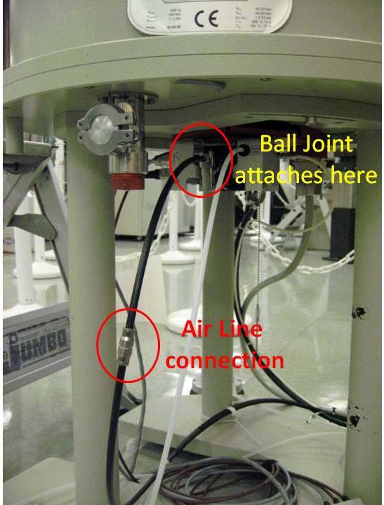
14 9. Turn off the VT in edte. This will turn off the probe heater, and it s now safe to unhook the air lines to the probe. 10. It helps to have two people for the next several steps, one working by the instrument, the other at the computer. Insert the heat exchanger into the liquid nitrogen Dewar. Connect the tube with the ball joint to the probe. Be careful, the clip is magnetic! Connect the black air line from the heat exchanger to the air line. Undo the "double female" connector and attach the heat exchanger's air line to the air line that runs to the back of the console. This connector is currently black plastic on the 400 and tan/gray plastic on the
15 15
16 11. As soon as the heat exchanger is in line, turn the probe heater back on in edte. You do not want to have the cold air running into the probe without the probe heater on, as this will cause the probe temperature to plummet very fast. Set your target temperature for 10 ºC and the gas flow for l/h. WATCH TO MAKE SURE THE PROBE TEMPERATURE DOES NOT DROP DANGERUOSLY FAST. 12. Set your Target Temperature (10 C increments, with 5 minutes of stability in between each increment) and adjust the Target Gas Flow as necessary. You may have to increase the gas flow from 200 l/h to help the instrument get down to temperature. DO NOT CRANK UP THE GAS FLOW TO MAKE THINGS GO FASTER. Be patient! Recommended Target Gas Flow Rates Sample T (in ºC) Gas Flow Rate (l/h) -150 to -80 ºC -80 to 0 ºC 0 to +25 ºC 300 to to to 300 Keep in mind these are ranges. You may need to try more than one value in order to maintain your target temperature. 13. In the Monitoring tab, watch for any signs of trouble. If you see the Current Temperature or Current Power changing erratically, let a DCIF staff member know IMMEDIATELY. Never leave the NMR unattended while conducting a VT experiment. 14. Once the Target Temperature has been reached and the Probe Temperature in the bottom status bar has been green and stable for 10 minutes, close the Temperature Control Suite by clicking the X in the upper right corner of the Temperature Control Suite window. 15. Check your lock level. Retune and reshim the instrument. You may now collect a spectrum. 16. When you are finished, bring the probe back up to 0ºC (adjust gas flow rate as needed) in 10 increments. Once the sample temperature has reached 0ºC, pull the heat exchanger out of the Dewar and set it on the floor. DO NOT TURN OFF THE GAS FLOW OR DISCONNECT THE AIR LINES FROM THE PROBE. The lines from the heat exchanger are short, you may need to tip the Dewar a bit to help you pull the heat exchanger out. It helps to have two people do this. Do not yank on or twist the gas lines! 16
17 17. Set the target temperature to 10 ºC and allow it to come up to about 15 ºC. 18. Turn off the probe heater (turn off the VT in the edte) and return all air lines to their default position. Disconnect the heat exchanger from the probe. Select the correct carrier gas (valves on the wall) that means air for room temperature. 19. Turn the probe heater back on (turn on the VT in the edte) and set the Target Temperature to 25ºC. Set the Target Gas Flow back to 400 l/h and wait for the probe temperature to return to 25ºC before closing the Temperature Control Suite, exiting TopSpin, and logging off the computer. NOTE: If the VT needs to be reset, you can do this by closing edte and then TopSpin. On the floor by the magnet should be a small tan TC-T2 box. Disconnect the cable from the TC-T2 box, reconnect it, open TopSpin, and type edte. NEVER TURN OFF THE GAS FLOW TO THE PROBE. Any questions? Please contact the DCIF staff! DO NOT attempt anything in this document until AFTER you have been trained by the DCIF staff! NEVER turn off the gas flow to the probe while the VT is on!!! 17
Justin Douglas KU NMR Labs v1 10/29/09
 High Temperature NMR Justin Douglas (justindouglas@ku.edu) KU NMR Labs v1 10/29/09 Special Note: This guide is intended to supplement proper training and formal check out by the NMR facility manager. Improper
Temperature Control and VT Experiments on Varian Spectrometers
 Varian Users Guide Pg 1 Temperature Control and VT Experiments on Varian Spectrometers updated: 2008 Feb 19 Calibration of Sample Temperature: See section 3.5.3 in Claridge, and/or use the thermocouple
User Manual. Digi-Sense TC9500 Advanced Multiparameter Temperature Controller with Thermocouple, Thermistor, and RTD Inputs
 User Manual Digi-Sense TC9500 Advanced Multiparameter Temperature Controller with Thermocouple, Thermistor, and RTD Inputs Models 89800-03 and 89800-04 THE STANDARD IN PRECISION MEASUREMENT Table of Contents
User Manual. Digi-Sense TC9600 Advanced Multiparameter Temperature Controller with Thermocouple, Thermistor, and RTD Inputs
 User Manual Digi-Sense TC9600 Advanced Multiparameter Temperature Controller with Thermocouple, Thermistor, and RTD Inputs Models 89800-13 and 89800-14 THE STANDARD IN PRECISION MEASUREMENT Table of Contents
Digi-Sense TC9000 Advanced PID and On/Off Temperature Controller with Thermocouple Input
 User Manual 99 Washington Street Melrose, MA 02176 Phone 781-665-1400 Toll Free 1-800-517-8431 Visit us at www.testequipmentdepot.com Digi-Sense TC9000 Advanced PID and On/Off Temperature Controller with
Autoclave Operations Manual
 UNIVERSITY OF ILLINOIS AT URBANA/CHAMPAIGN - COMPOSITES MANUFACTURING LAB Autoclave Operations Manual Version 1 Written by KRH 2/21/2011 Contents ACCS... 4 Alarms... 7 Main Display Tabs... 7 Process Control
NMR SAMPLING ACCESSORIES CLEANING NMR SAMPLE TUBES
 CLEANING NMR SAMPLE TUBES It is important to understand that NMR sample tubes are NOT laboratory glassware and should not be treated as such. Because of the precision tolerances and the very thin wall
Oakton TEMP 9500 Advanced Multiparameter Controller
 Oakton TEMP 9500 Advanced Multiparameter Controller Models: 89800-03 & 89800-04 Oakton Instruments 625 E Bunker Ct. Vernon Hills, IL 60061, USA 1-888-4OAKTON (1-888-462-5866) info@4oakton.com Contents
ELECTRONIC COMMUNICATING THERMOSTAT
 O M N I S T A T ELECTRONIC COMMUNICATING THERMOSTAT Installation Manual RC-81 Single Stage Heat/Cool Real Time Pricing System Document Number 13I00-2 January, 1997 Copyright 1997 Home Automation, Inc.
MVE TS Controller (Touch Screen)
") MVE TS Controller (Touch Screen) Quick Reference Guide i Table of Contents Product Identification Display / Control Panel................................................. 2 Bottom Panel / Electrical /
MVE TS Controller (Touch Screen) Quick Reference Guide i Table of Contents Product Identification Display / Control Panel................................................. 2 Bottom Panel / Electrical /
Tempco Part Number PCT30006 Temperature Control Enclosure with Relay Output for Tote Tank Heating Applications
 Instruction Manual Tempco Part Number PCT30006 Temperature Control Enclosure with Relay Output for Tote Tank Heating Applications Manual PCT30006, Revision 9/20/2016 The PCT30006 control enclosure incorporates
Autofire Express Ramp/Hold Controller Instruction Guide
 ra1 = 0250 F 1 = 0750 HLd1 = 00.00 ra2 = 0900 F 2 = 1425 HLd2 = 00.30 ra3 = FULL F 3 = 1050 HLd3 = 00.00 ra4 = 0150 F 4 = 0750 HLd4 = 00.00 ra5 = 0000 4. The display shows Strt after the final entry above.
Tempered Water Logic Control OPERATION l TROUBLE SHOOTING
 Tempered Water Logic Control OPERATION l TROUBLE SHOOTING English For MPE Multiple Chiller Units Control Panel TEMPERED WATER SYSTEMS L-2199 Rev. 20080223 Revision: L-2199 20101104 *** IMPORTANT NOTICE
MODEL SF-10 CONTROL OPERATION AND INSTRUCTION MANUAL
 MODEL SF-10 CONTROL OPERATION AND INSTRUCTION MANUAL The SF-10 Temperature Control () is an efficient boiler operator with a digital LCD display with backlight, a boiler pump output, and an alarm. The
RC-112 Two Speed Heat Pump 3 Stage Heat / 2 Stage Cool With Energy Efficient Control
 O M N I S T A T ELECTRONIC COMMUNICATING THERMOSTAT Installation Manual RC-112 Two Speed Heat Pump 3 Stage Heat / 2 Stage Cool With Energy Efficient Control Document Number 13I00-5 November, 1997 CONTENTS
For Quick Set-Up go to Page 14
 Talking Thermostat Model VT3000 Guide SmartWay Solutions, Inc. US Patent 6,608,560 & 7,62,253 For Quick Set-Up go to Page 4 Model VT3000, a universal thermostat for use on most Gas or Electric, Conventional
HEAT PUMP PROGRAMMABLE THERMOSTAT
 HEAT PUMP PROGRAMMABLE THERMOSTAT SA PM 3 COOL TEMP Form 44014-01 r010408 Model 43168 Owners Manual 1 Congratulations! Heat Pump Programmable Thermostat Model 43168 THERMOSTAT CONTROLS Switches & Buttons...15
HERMS (Heat Exchanger Recirculating Mash System) Controller
 Controller") HERMS (Heat Exchanger Recirculating Mash System) Controller Your new HERMS controller Thanks for buying your controller from us!!! Your controller is based on two MYPIN TA4 series PID controllers. Unlike
HERMS (Heat Exchanger Recirculating Mash System) Controller Your new HERMS controller Thanks for buying your controller from us!!! Your controller is based on two MYPIN TA4 series PID controllers. Unlike
800 MHz US 2 NMR system
 800 MHz US 2 NMR system To achieve ultra-high-fields (>700 MHz), the magnet must be cooled to below (ambient pressure) liquid He temperature. The He cryostat is divided into two sections. The upper section
Quick-Start Guide Digi-Sense TC9000 Advanced PID and On/Off Temperature Controller with Thermocouple Input Models and
 Quick-Start Guide Digi-Sense TC9000 Advanced PID and On/Off Temperature Controller with Thermocouple Input THE STANDARD IN PRECISION MEASUREMENT 1 Getting Started: 7 6 2 1 Front 5 4 3 1) RUN/STOP Button
Refrigerated air dryers
 Refrigerated air dryers OPERATING AND MAINTENANCE MANUAL Original instructions 38178800319 OPERATING AND MAINTENANCE MANUAL - Contents 1 CONTENTS CONTENTS... 1 Chapter 1 IDRY ELECTRONIC CONTROLLER...
RC-101 Heat Pump Real Time Pricing System 2 Stage Heat / 1 Stage Cool
 O M N I S T A T ELECTRONIC COMMUNICATING THERMOSTAT Installation Manual RC-101 Heat Pump Real Time Pricing System 2 Stage Heat / 1 Stage Cool Document Number 13I00-4 January, 1997 Copyright 1997 Home Automation,
VF X Series. User Manual. SKOPE Vertical Freezer. MAN11137 Rev. 1.1 Sep VF650X
 VF X Series SKOPE Vertical Freezer MAN11137 Rev. 1.1 Sep. 2016 VF650X SKOPE Warranty Protection Register now for peace of mind It s quick and simple. Take a few minutes to register your SKOPE product and
Tempco PCT-3000 Series Temperature Control Console with Relay Output for Heating or Cooling Applications
 Instruction Manual Tempco PCT-3000 Series Temperature Control Console with Relay Output for Heating or Cooling Applications Manual PCT-3000 Revision 9/2014 The PCT-3000 series control console incorporates
Linkam Scientific Instruments
 Probe Systems for Microscopy and Spectroscopy There are many applications that require the measurement of electrical parameters whilst making microscopic or spectroscopic observations. Linkam have designed
THERMAL PROCESSING THEORY
 THERMAL PROCESSING THEORY 9.1 Infrared Waves Infrared waves form part of the electromagnetic spectrum. Electromagnetic waves with wavelengths from 0.78 µm to 1000 µm are called infrared waves. You are
Oven Control System Operation - Ver 2.8
 Version 2.8 - Pg:1 - Ver 2.8 This operation manual contains important information about your oven. All operators should review this manual before operating the oven. When you turn on the switch, the control
XSTREAM Valve System With A.R.M.E.D. Technology Service & Installation Instructions Page 1
 Page 1 WHY should I install the XSTREAM Valve System? XDX is more efficient, saving on power consumption. Use of XDX system decreases defrost cycles. XDX maintains more consistent product temperatures,
# TFB-S-120, TFB-L-120 TFB-S-220, TFB-L-220 FWS-S-120, FWS-L-120 FWS-S-220, FWS-L-220
 Tissue Flotation Bath Flotation Work Station Catalog # TFB-S-120, TFB-L-120 TFB-S-220, TFB-L-220 FWS-S-120, FWS-L-120 FWS-S-220, FWS-L-220 Operator s Manual Version 1.3, Jan 2012 Be certain to read this
RC-90 / RC-90B Single Stage Heat/Cool Thermostat for Zone Control Systems Installation Instructions
 RC-90 / RC-90B Single Stage Heat/Cool Thermostat for Zone Control Systems Installation Instructions DESCRIPTION The RC-90 is a precision digital thermostat designed for 24 VAC single stage heating and
User manual and installation guide
 User manual and installation guide 31046005 Copyright Phason Inc. All rights reserved. Printed in Canada About the manual The manual describes the features of your control and how to use them; it does
Welcome to Unilux VFC Wall-mount Thermostat
 Welcome to Unilux VFC Wall-mount Thermostat User Guide Welcome to your new home and Unilux VFC Wall-mount Thermostat. Please refer to this user guide to help set up your thermostat. Table of Contents Unilux
OIL COOLER INSTRUCTION HANDBOOK
 OIL COOLER INSTRUCTION HANDBOOK INDEX 1. GENERALITY 2 1.1 OPERATING RANGE 1.2 IMPORTANT 2. INSTALLATION 3 2.1 TRANSPORTATION 2.2 INSTALLATION LOCATION 2.3 PIPING 2.4 WIRING (see the electrical diagram
Set & $ave. Model Programmable Thermostat. installation and operation manual
 Set & $ave Programmable Thermostat installation and operation manual Model 44110 42707-01 8-21-06 2 Table of Contents Important Information... 5 Tools... 6 Uninstalling the Existing Unit... 7 Installing
QD-ENG-68 Controller for Thermoelectric Thermal Management
 INSTALLING THE CONTROLLER QD-ENG-68 Controller for Thermoelectric Thermal Management The Ice Qube TMS controller is shipped complete with mounting hardware and electrical cables for easy installation.
PHASE DMC USER S MANUAL
 PHASE 7.4.2 DMC USER S MANUAL American Dryer Corporation 88 Currant Road, Fall River MA 02720-4781 USA Telephone: +1 (269) 923-3000 / Fax: +1 (508) 678-9447 e-mail: mdl-service@whirlpool.com / www.adclaundry.com
PRO SERIES IMPORTANT SAFETY INFORMATION
 INSTALLATION INSTRUCTIONS & HOME OWNERS MANUAL PRO SERIES IMPORTANT SAFETY INFORMATION When installing or using any high voltage electrical appliance, basic safety precautions should always be followed.
Spas with 2 or 3 Pumps
 Topside Control Instructions for Spas with 2 or 3 Pumps 15bp501tp60102 1 Programming Menu Sequence 2 Powering on Your Spa After filling the spa through the filter assembly to the correct level remove the
INSTALLATION & USER MANUAL
 INSTALLATION & USER MANUAL HC Digital Automatic Humidistat (Y3760) CONTROLS 506808-01 3/2016 Supersedes 6/2011 picture goes here THIS MANUAL MUST BE LEFT WITH THE HOMEOWNER FOR FUTURE REFERENCE NOTICE
PRO Installation. Thermostat Wi-Fi
 PRO Installation Thermostat Wi-Fi 1 Designed by the pros for the pros There are a lot of choices when it comes to buying a thermostat, but only one combines 125 years of experience and the latest connected
VF Series. User Manual. SKOPE Vertical Freezer. MAN10521 Rev. 3.3 Jun VF1000
 VF Series SKOPE Vertical Freezer MAN10521 Rev. 3.3 Jun. 2016 VF1000 SKOPE Warranty Protection Register now for peace of mind It s quick and simple. Take a few minutes to register your SKOPE product and
ACQUITY UPLC HT Column Heater Instructions
 ACQUITY UPLC HT Column Heater Instructions Note: This document is an addendum to Revision C of the ACQUITY UPLC System Operator s Guide. Contents: Topic Page Overview 1 Connecting the cable 4 Installing
HOBO U14 Data Logger User Manual
 HOBO U14 Data Logger User Manual The U family of data loggers offers reliability and convenient monitoring for applications that require higher accuracy, better resolution, more memory, or USB connectivity
The EGT-1 is a single channel fully programmable digital EGT (Exhaust Gas Temperature) gauge.
 gauge.") EGT-1 EGT (Exhaust Gas Temperature) Gauge Operating Manual English 1.02 Introduction The EGT-1 is a single channel fully programmable digital EGT (Exhaust Gas Temperature) gauge. The EGT-1 s high accuracy
EGT-1 EGT (Exhaust Gas Temperature) Gauge Operating Manual English 1.02 Introduction The EGT-1 is a single channel fully programmable digital EGT (Exhaust Gas Temperature) gauge. The EGT-1 s high accuracy
Table Of Contents
 DRS25 User s Guide Table Of Contents Chapter 6: Profile Tutor Software 6 Profile Tutor Guide...3 6.0 Physical Set Up...4 6.1 Running Profile Tutor Software...5 6.2 Overview of the Tutor Events...8 6.3
HOMEADVANTAGE II IMPORTANT SAFETY INFORMATION
 INSTALLATION INSTRUCTIONS & HOME OWNERS MANUAL HOMEADVANTAGE II HA008240 HA011240 HA013240 HA018240 HA024240 HA027240 HA036240 IMPORTANT SAFETY INFORMATION When installing or using any high voltage electrical
Dixell Installing and Operating Instructions release 7.0
 XR160C - XR160D - XR170C - XR170D - XR162C - XR172C CONTENTS 1. GENERAL WARNING 2 1.1 Please read before using this manual 2 1.2 Safety Precautions 2 2. GENERAL DESCRIPTION 2 3. CONTROLLING LOADS 2 3.1
LeakSafe. solutions. WaterSwitch2. Installation Instructions
 LeakSafe solutions TM WaterSwitch2 Installation Instructions QUICK USER GUIDE 1. Turning water ON or OFF using the WaterSwitch Valve Control To turn the water ON, press and hold down the WATER ON button
Exercise 2-4. Heat Exchangers (Optional Exercise) EXERCISE OBJECTIVE DISCUSSION OUTLINE. Description of a brazed plate heat exchanger DISCUSSION
 EXERCISE OBJECTIVE DISCUSSION OUTLINE. Description of a brazed plate heat exchanger DISCUSSION") Exercise 2-4 Heat Exchangers (Optional Exercise) EXERCISE OBJECTIVE In this exercise, you will become familiar with plate heat exchangers. You will set up a cooling and a heating loop passing through the
Exercise 2-4 Heat Exchangers (Optional Exercise) EXERCISE OBJECTIVE In this exercise, you will become familiar with plate heat exchangers. You will set up a cooling and a heating loop passing through the
! WARNING To avoid risk of electrical shock, personal injury or death; disconnect power to oven before servicing, unless testing requires power.
 Technical Information Electric Slide-In Range JES8850ACB/S/W JES9750ACB/W JES9800ACB/S/W JES9860ACB/S/W Due to possibility of personal injury or property damage, always contact an authorized technician
MODEL EM-10 ELECTRIC BOILER CONTROL OPERATION AND INSTRUCTION MANUAL
 MODEL EM-10 ELECTRIC BOILER CONTROL OPERATION AND INSTRUCTION MANUAL The EM-10 Boiler Temperature Control (BTC) is an efficient boiler operator with a digital LCD display with backlight, a boiler pump
Thermohygrometer with Single Type K Input and Superheat Function
 User Manual 99 Washington Street Melrose, MA 02176 Phone 781-665-1400 Toll Free 1-800-517-8431 Visit us at www.testequipmentdepot.com Thermohygrometer with Single Type K Input and Superheat Function with
Smart Temp. Model
 Smart Temp Model 42-160 SINGLE STAGE PROGRAMMABLE THERMOSTAT 1 Heat / 1 Cool Single Stage Thermostat. 5+2 Programmable, Compatible with Gas Heat & Heat Pump System Installation and Operation Manual SPECIFICATIONS:--------------------------------------------------------------------------------
GMH 285 / GMH 285-BNC
 GMH 285 GMH 285-BNC H69.0.01.6C-02 Operating Manual Pt1000 Precision Thermometer For exchangeable probes, with alarm as of version V1.0 GMH 285 / GMH 285-BNC GMH-GREISINGER GMH-GREISINGER WEEE-Reg.-Nr.
Jetstream Series HPLC - PELTIER COLUMN-THERMOSTATS 1. GENERALITIES
 Generalities HPLC - PELTIER COLUMN-THERMOSTATS GENERALITIES This manual has been updated to the actual standard. It now covers all the features of the actual Jetstream series models. All rights concerning
Service Settings. EASY PFA Universal Biomass Heating System Controller. Technical Documentation
 Service Settings EASY PFA Universal Biomass Heating System Controller Technical Documentation Safety Precautions Caution! Schock Hazard! Risk of electrical schock which may cause serious injuries or death.
OPERATING MANUAL TORREY PINES SCIENTIFIC, INC. DIGITAL HPLC COLUMN HEATER MODEL CO20 DOCUMENT NUMBER CO20-00
 OPERATING MANUAL TORREY PINES SCIENTIFIC, INC. DIGITAL HPLC COLUMN HEATER MODEL CO20 DOCUMENT NUMBER CO20-00 Torrey Pines Scientific, Inc 2713 Loker Ave. West Carlsbad, CA 92010 Phone: 760-930-9400 Fax:
portable induction cooktop Instruction Booklet Model ID1350
 portable induction cooktop Instruction Booklet Model ID1350 IMPORTANT SAFEGUARDS When using electrical appliances, basic safety precautions should always be followed including the following: 1. Read all
G A S W A TE R /A G U A
 G A S W A TE R /A G U A Congratulations! You've just purchased a new Marey Portable tankless water heater and will soon begin to enjoy the benefits of going tankless. Take the time to thoroughly read and
INSTALLATION INSTRUCTIONS & HOME OWNERS MANUAL ECO 18 ECO 24 ECO 27 IMPORTANT SAFETY INFORMATION
 INSTALLATION INSTRUCTIONS & HOME OWNERS MANUAL ECO 18 ECO 24 ECO 27 IMPORTANT SAFETY INFORMATION As when installing or using any high voltage electrical appliance, basic safety precautions should always
PL-1 Thermostat User s Guide
 Table of Contents Introduction... 1 PL-1 Thermostat User s Guide Version 2.0 Firmware Version 2.0 Conventions... 2 Front Panel Layout... 3 Thermostat Modes... 4 Thermostat Mode Programming... 5 Set Point
Digital Refrigerant System Analyzer. MAXMIN Psi kpa Bar MPa C F R TIME P T UNITS
 Digital Refrigerant System Analyzer INSTRUCTION MANUAL ENGLISH LOW START PRS T-LOW SUPERHEAT MAXMIN kpa Bar MPa R TIME P T HIGH END PRS T-HIGH SUBCOOL VAC 1-800-547-5740 Fax: (503) 643-6322 www.ueitest.com
Halo Programmable LED Aquarium Light. Quick Start Guide
 Halo Programmable LED Aquarium Light www.tiaojiou.com Quick Start Guide 1. FEATURES - 25 LED array delivering rich color spectrum - Two groups (channels) of LEDs to optimize the light - Embedded Timers
Psychrologix Controller W/ DHC
 Psychrologix Controller W/ DHC User Manual For Psychrologix version 1.3 Please read this entire document before connecting the Psychrologix controller. 1 *IMPORTANT PLEASE NOTE The Following: First, a
Quick start guide for Altrix Precision Temperature Management System
 Quick start guide for Altrix Precision Temperature Management System Setup Fill the reservoir! Caution Always use sterile distilled water or water that has been passed through a filter less than or equal
Chiltrix 5.1 Thin DC - Inverter Water Fan Coil Unit Floor, Wall or Ceiling Universal Mount Manual
 Chiltrix 5.1 Thin DC - Inverter Water Fan Coil Unit Floor, Wall or Ceiling Universal Mount Manual Version 1.5 1 CONTENTS CHAPTER 1 GENERAL INTRODUCTION...3 1. Preface... 3 2. Product Introduction... 3
RC-122BZ Two Stage Heat/Cool 2 Stage Heat / 2 Stage Cool Thermostat Installation Instructions
 RC-122BZ Two Stage Heat/Cool 2 Stage Heat / 2 Stage Cool Thermostat Installation Instructions DESCRIPTION The RC-122BZ is a precision digital thermostat designed for 24 VAC two-stage heating and cooling
- Data Brochure D 260. Boiler Control /09
 - Data Brochure Boiler Control 260 D 260 03/09 The Boiler Control 260 is designed to control a single stage heat source in order to provide outdoor reset or Domestic Hot Water () operation. The control
Series Temperature Controller Instruction Sheet
 Series Temperature Controller Instruction Sheet Thank you very much for purchasing DELTA A Series. Please read this instruction sheet before using your A series to ensure proper operation and please keep
Tune-Rite Software Operation Manual
 Software Operation Manual P/N: 0024-9504 Revision 0 July 2014 Product Leadership Training Service Reliability Table of Contents SECTION 1. INTRODUCTION... 3 SECTION 2. SAFETY... 4 2.1. Conventions... 4
SSV-DC user manual. Phason
 Phason SSV-DC user manual The SSV-DC has a 0 to 10 VDC signal output and a disconnect relay that allows you to easily and effectively control up to 10 variable frequency drives, slave units, modulating
2 THERMOSTAT DETAILS 3 REMOVING OLD THERMOSTAT
 CONTENTS Installation Instructions for Heating & Air Conditioning 1F79 n-programmable Heat Pump Thermostat Preparations... 1 Thermostat Details... 1 Removing Old Thermostat... 1-2 Mounting and Wiring...
Instruction Manual for HX-DX and HX-DXHP Heat Exchangers 3 / 2017
 Instruction Manual for HX-DX and HX-DXHP Heat Exchangers 3 / 2017 Model No. HX-36DX Model No. HX-120DX Check packing slip and product to see if they match. If not, contact Aqua Logic immediately!! Important:
Installation and user manual
 Installation and user manual Please read carefully and retain for future reference Models EcoHeat: C3, C5, C6, C8, C9, C11, C12 Rev.1_09-07-15 Page 1 Table of Contents 1 IMPORTANT: WARNINGS 1.1 GENERAL
PHASE COIN USER S MANUAL
 PHASE 7.3.2 COIN USER S MANUAL American Dryer Corporation 88 Currant Road Fall River, MA 02720-4781 Telephone: (508) 678-9000 / Fax: (508) 678-9447 E-mail: techsupport@amdry.com www.amdry.com ADC Part
Settings and Maintenance of the CombinAir
 Atmos CombinAir Settings and Maintenance of the CombinAir Issue 13.8.10 Operation and commissioning: The control unit on the front of the CombinAir is used to adjust the settings during commissioning.
LeakSafe. solutions. WaterSwitch2. Installation Instructions
 LeakSafe solutions TM WaterSwitch2 Installation Instructions WATERSWITCH2 COMPONENTS WaterSwitch2 Valve Control Extended Range Valve Driver Valve Water Flow Sensor Leak Detection tape available in 0.3M
DEHUMIDIFIER OWNER S MANUAL. Read this manual carefully before operating the appliance and retain it for future reference.
 OWNER S MANUAL DEHUMIDIFIER ESPAÑOL FRANÇAIS Read this manual carefully before operating the appliance and retain it for future reference. Model : UD701KOG1 P/NO : MFL68026017 www.lg.com TABLE OF CONTENTS
Programmable Thermostat
 Set & $ave Programmable Thermostat Installation and Operation Manual English Model 44360 Form# 42710-01 20091204 2009 Hunter Fan Co. 2 Table of Contents Important Information... 5 Tools... 6 Uninstalling
ST Wiring diagram. Product description. Four-stage controller. Order number
 ST96-35.16 Four-stage controller Order number 99.2 Wiring diagram Product description The four-stage controller with 4-digit setpoint and actual value display, 3 keys and 4 relays was developed for the
TEMPERATURE CONTROLLER (STANDARD MODEL)
") OPERATING MANUAL TEMPERATURE CONTROLLER (STANDARD MODEL) 689-0000 689-0005 Barnant Company 28W092 Commercial Avenue Barrington, Illinois U.S.A. 60010-2392 (847) 381-7050 (847) 381-7053 (Fax) 800-637-3739
OPERATING MANUAL TEMPERATURE CONTROLLER (STANDARD MODEL) 689-0000 689-0005 Barnant Company 28W092 Commercial Avenue Barrington, Illinois U.S.A. 60010-2392 (847) 381-7050 (847) 381-7053 (Fax) 800-637-3739
Varlogic NRC12. Power factor controller. User manual
 Varlogic NRC12 Power factor controller User manual Menu Structure First Startup Startup after preconfiguration Language selection Language selection Main Menu BANK PRECONF AUTO SETUP MANUAL SETUP MEASUREMENTS
B-40/B-41 Modulating Temperature Controller
 INSTALLATION & OPERATING INSTRUCTIONS B-40/B-41 Modulating Temperature Controller For Raytherm Boilers & Water Heaters H2 514-4001 WH2 2100-4001 Catalog No. 5000.70 Effective: 12-21-11 Replaces: NEW P/N
Alarms Updated 03/26/2018
 Updated 03/26/2018 Table of Contents Alarms Alarms in OneView...1 Types of Alarms...1 Setting up Alarms...2 Alarm Configuration...4 Customize Alarm Parameters...5 List of Configured Alarms...7 Acknowledging
MODEL AND MODEL GAS PROPORTIONAL DETECTORS. December 2016 Serial No and Succeeding Serial Numbers
 MODEL 43-37 AND MODEL 43-37-1 GAS PROPORTIONAL DETECTORS Serial No. 086152 and Succeeding Serial Numbers MODEL 43-37 AND MODEL 43-37-1 GAS PROPORTIONAL DETECTORS Serial No. 086152 and Succeeding Serial
HP727S. Single speed swimming pool heat pump controller Operation manual TABLE OF CONTENTS
 HP727S Single speed swimming pool heat pump controller Operation manual TABLE OF CONTENTS 1. General Description 2. Specifications 3. Installation Instructions 4. Electrical Wiring 5. Instrument Wiring
918TS Manual 1/26/09-1 -
 918TS Manual 1/26/09-1 - Table Of Contents: FEATURES...3 INSTALLATION...5 POWERING ON / INITIAL SETUP...5 SETTING DELIEVRY PRESSSURE... 7 OPTIONS & SETTINGS...8 ALARM NOTIFICATION TABLE...10-2 - FEATURES
1F Non-programmable Electronic Digital Heat Pump Thermostat INSTALLATION AND OPERATION INSTRUCTIONS
 FAILURE TO READ AND FOLLOW ALL INSTRUCTIONS CAREFULLY BEFORE INSTALLING OR OPERATING THIS CONTROL COULD CAUSE PERSONAL INJURY AND/OR PROPERTY DAMAGE. DESCRIPTION Your new White-Rodgers Digital Thermostat
TEMPERATURE CONTROLLER R/S (ADVANCED MODEL)
") OPERATING MANUAL TEMPERATURE CONTROLLER R/S (ADVANCED MODEL) 689-0010 689-0015 Barnant Company 28W092 Commercial Avenue Barrington, Illinois U.S.A. 60010-2392 (847) 381-7050 (847) 381-7053 (Fax) 800-637-3739
OPERATING MANUAL TEMPERATURE CONTROLLER R/S (ADVANCED MODEL) 689-0010 689-0015 Barnant Company 28W092 Commercial Avenue Barrington, Illinois U.S.A. 60010-2392 (847) 381-7050 (847) 381-7053 (Fax) 800-637-3739
Table of Contents SECTION PAGE
 Table of Contents SECTION PAGE SECTION 1 INTRODUCTION................... 1.1 Description.............................. 1.2 Features................................ 1.3 Models.................................
MYSTICOOL Max Valve System with Xstream and A.R.M.E.D. Technology Service & Installation Instructions Page 1
 Page 1 WHY should I install the MYSTICOOL Max Valve System? XDX is more efficient, saving on power consumption. Use of XDX system decreases defrost cycles. XDX maintains more consistent product temperatures,
IntelliSync Thermostat / Mobile App Frequently Asked Questions
 IntelliSync Thermostat / Mobile App Frequently Asked Questions This FAQ page addresses the most common questions on Deriva IntelliSync. Why bother setting a heating and cooling schedule? What is ENERGY
Portable Air-conditioner
 Use and Care Manual Portable Air-conditioner Thank you very much for selecting this new model of Portable Air Conditioner, please read this Use and Care Manual carefully before installing and using this
TMC. Installation and Operation Manual TMC. Temperature and Pressure Monitoring for Heating and Cooling Applications. Temperature Monitoring Control
 Installation and Operation Manual Temperature and Pressure Monitoring for Heating and Cooling Applications Temperature Monitoring Control VALVE OPEN ALARM System= 128 o F Alarm At= 130 o F RESET /BACK
Indoor Air Quality Meter Rev. 2.x Meters. The Value Leader TM
 Indoor Air Quality Meter 1010 Rev. 2.x Meters The Value Leader TM www.tpi-thevalueleader.com Contents 1. Introduction 2. General Overview 3. Familiarization 3.1 Front View 3.2 Soft Keys 3.3 Back View 4.
User Guide ems25plus. Page 1. Normal operation. Product interface
 Page 1 Product interface rmal operation During normal operation, EMS controllers display the information below. Assuming the product temperature is correct when the outlet is open, this means that the
OVEN INDUSTRIES, INC.
 OVEN INDUSTRIES, INC. OPERATING MANUAL Model 5C7-252 TEMPERATURE CONTROLLER With PLC Inputs Introduction Thank you for purchasing our controller. The Model 5C7-252 is an exceptionally versatile unit and
RC-2000 Thermostat Installation Instructions
 RC-2000 Thermostat Installation Instructions DESCRIPTION The RC-2000 is a precision digital thermostat designed for 24 VAC heating and cooling systems. The RC-2000 will support the following systems: Single
SolaStat An Intelligent Technology Solution for Water Heating USER GUIDE
 SolaStat -2-3 An Intelligent Technology Solution for Water Heating USER GUIDE Table of Contents Introducing your SolaStat Controller... 1 The Display Panel... 2 Saving Power with SolaStat... 3 Using your
JAG group microwave manual. (updated October ) Table of contents. 1 General information 2. 2 General safety rules 2. 3 The microwave reactor 3
 Table of contents. 1 General information 2. 2 General safety rules 2. 3 The microwave reactor 3") JAG group microwave manual (updated October 4 2016) Table of contents 1 General information 2 2 General safety rules 2 3 The microwave reactor 3 3.1 Setup 3 3.2 Getting started 4 4 Reactions under pressure
JAG group microwave manual (updated October 4 2016) Table of contents 1 General information 2 2 General safety rules 2 3 The microwave reactor 3 3.1 Setup 3 3.2 Getting started 4 4 Reactions under pressure