SECTION COMMON WORK RESULTS FOR ELECTRONIC LIFE SAFETY AND SECURITY
|
|
|
- Clyde Bruce
- 5 years ago
- Views:
Transcription
1 SECTION COMMON WORK RESULTS FOR ELECTRONIC LIFE SAFETY AND SECURITY PART 1 - GENERAL 1.1 SECTION INCLUDES A. Cable Material Requirements. B. Cable Installation Requirements. 1.2 GENERAL REQUIREMENTS A. The requirements of the Contract Documents, including the General and Supplementary General Conditions, and Division 1 General Requirements shall apply to work of this Section. B. At the time of bid, all exceptions taken to these Specifications, any variances to the contract drawing design, and any non-conformance to the operating capabilities called for in this specification, shall be listed in writing and forwarded with the submission of the bid. Any such exception, variance, or non-conformance, which was not listed at the time of bid, and is identified in the submittal, shall be grounds for immediate disapproval without comment. C. Consultant shall reference district MAPPS facility utilization assessments to verify accuracy of room usage and placarding. The contractor is responsible for providing door placards. 1.3 RELATED SECTIONS A. District 11 Technical Guidelines 1.4 SUBMITTALS A. Reference Division 01 Submittal Procedures 1. Product Data: Provide manufacturer s data sheets showing product appearance, electrical characteristics, and connection requirements. 2. Manufacturer s Installation Instructions: Indicate application conditions and limitations of use, as stipulated by the product-testing agency. Include instructions for storage, handling, protection, examination, preparation, installation, and start-up or products. 3. Exceptions: Provide a details listing of any and all exceptions, variances, and non-conformances to the specifications and contract design drawings. Failure to disclose any such items shall be grounds for immediate disapproval of submittals without comment. 4. Samples: Provide samples of the following items. a. Provide a minimum of two (2) samples of all security cable to be installed on the projects. Cable samples shall be of sufficient length to identify cable marking (striping) and cable listing identification. b. provide a minimum of two (2) samples of all cable supporting devices, metal bridle rings, metal mounting brackets, plastic plenum rated wire bushings, and other applicable cable installation equipment to be utilized on the project. 1.5 QUALIFICATIONS A. Manufacturer: Company specializing in manufacturing the products specified in this section with a minimum three (3) years experience, and with service facilities within fifty (50) miles of the project. B. Fire Alarm Installer: Installing Company shall use only NESCO level SimplexGrinnell dealer for programming and final testing. The Bidding Company must specialize in installing the products specified in this section with a minimum three (3) years documented experience. The installer shall employ NICET Level 2 trained technicians to install the products specified in this Section.
2 C. Card Access Installer: Installing Company shall use only Identicard and HSS for programming and final testing of the Card Access System. The Bidding Company must specialize in installing the products specified in this section with a minimum three (3) years documented experience. The installer shall employ factory trained and certified technicians to install the products specified in this Section. PART 2 - PRODUCTS 2.1 ACCESS CONTROL/SECURITY AND SAFETY ALARM SYSTEM WIRE AND CABLE A. Cable for Class 1 Remote Control and Signal Circuits: Copper conductor, 600 volts insulation rated 75 degrees C, individual conductors twisted together, shielded, and covered with a non-metallic jacket, UL listed for use in air handling ducts, hollow spaces used as ducts, and plenums. B. Cable for Class 2 or Class 3 Remote Control and Signal Circuits: Copper conductor, 300 volts insulation rated 75 degrees C, individual conductors twisted together, shielded, and covered with a non-metallic jacket, UL listed for use in air handling ducts, hollow spaces used as ducts, and plenums. C. Miscellaneous Access Control/System Circuits: Power limited fire protective signaling cable for fire and smoke characteristics, copper conductor, 300 volts insulation rated 105 degrees C, UL listed for use in air handling ducts, hollow spaces used as ducts, and plenums. D. Use #18/4 AWG minimum size stranded conductors for security device initiating loop circuits. E. Provide wet environment exterior rated cable for underground raceway or exterior cable applications. F. Install all remote control and signal cables in raceways, or supported every 4 to 6 feet on bridal rings. PART 3 - EXECUTION 3.1 INSTALLATION A. Install products in accordance with manufacturer s instructions. B. Plenum rated cable. 1. Cable routing shall be perpendicular to or parallel to structural building members, and shall utilize a metal bridal ring type support system attached to structural building members only. 2. Mounting cable to other building systems (fire protection, electrical conduit, mechanical ductwork, etc.), or running cable in any fashion other than described, is strictly forbidden. C. Do not exceed 40% fill rate in raceways and back boxes. 1. For retrofit applications, conduit and box fill shall be assessed and approved by the Engineer and District. D. Minimum size for back boxes shall be 4 x 4 x 2-1/8. E. Combination speaker/strobe back boxes shall be ORBIT 4 x 4 x 3-1/2 with associated BH3 mounting bracket or approved equivalent. F. The use of extension rings on new or retrofit construction shall be approved on a case-by-case basis by the Engineer and District. G. Junction boxes for any new or retrofit construction, that have more than four (4) wire splice connections, shall utilize WAGO connectors ( or equivalent as approved by District project manager.
3 H. Provide Wiremold or Plastic surface raceway in all areas that are exposed to the Public. Paint to match existing wall or ceiling finish, unless approved by the Engineer and District. Paint to match existing wall or ceiling finish, unless approved by the Engineer or District. Knockouts are not permitted in exposed back boxes installed in public areas. 1. Conduit shall be provided in exposed joist construction and concealed spaces. Contractor shall utilize Wiremold where permitted in writing by Jefferson County for surface mount in locations accessible to the public. Contractor shall obtain approval from Jefferson County or engineer representative for Wiremold and conduit locations. 2. Conduit shall be in accordance with The National Electrical Code (NEC), local and state requirements. 3. Conduit is not permitted to be secured to the roof deck. All existing conduit utilized for fire alarm shall be removed if improperly secured to the roof deck and new conduit shall be installed. Conduit shall be installed in accordance with NEC spacing requirements from the roof deck. 4. All conduit shall be installed by a licensed electrician. 5. All conduit shall be red, hot-galvanized, fire alarm EMT. Conduit shall be painted to match existing surface if requested by owner. 6. Cable must be separated from any open conductors of power, or Class 1 circuits, and shall not be placed in any conduit, junction box or raceway containing these conductors, per NEC. 7. Conduit shall not enter the fire alarm control panel, or any other remotely mounted control panel equipment or back boxes, except where conduit entry is specified by the FACP manufacturer. 8. Conduit shall be trade size 3/4-inch (19.1 mm) minimum. ½-inch conduit may be allowed if the contractor submits a specific request in writing. 9. Conduit edge protection shall be provided for all transitions from conduit to bridle rings. Reference Open (Plenum) Cable Installation Requirements. 10. Conduit sleeves shall be used for all penetrations through fire rated or non-fire rated walls and partitions. Sleeves through fire rated walls shall be fire caulked on both sides of the wall and filled after cable installation. 11. Knockouts are not permitted in exposed back boxes installed in public areas. Provide and install surface skirts for all surface mounted devices. I. Support all boxes by All-thread or other approved box support device; or bolt directly to building structural members. Do not support boxes to ceiling tie-wires. J. Provide marking paint on support hardware. Red for Fire Alarm, Green for Security and Blue for Video Surveillance systems. Do not allow paint to contaminate any wire. K. Mount end-of-line device in box with last device. L. Mount outlet box for electric door holder to withstand 80 pounds pulling force. Where wall construction is wood or steel frame, utilize Caddy telescopic bracket TSGB16/TSGB24 or approved equivalent.
4 M. Division 28 contractor shall make conduit and wiring connections to door release devices, sprinkler flow switches, sprinkler valve tamper switches, duct smoke detectors, smoke/fire dampers, HVAC units, and other applicable devices, furnished under other Sections. N. Automatic Detector Installation: Conform to NFPA 72. O. Automatic Duct Detector Installation: Conform to NFPA 90A. When patching ducts, utilize steel plates secured by #8 x ½ indented slotted hex washer head type A sheet metal screws and apply mastic which is listed and labeled 181A-M in accordance with UL 181A. Do not use tape. 3.2 OPEN (Plenum) CABLE INSTALLATION REQUIREMENTS A. Open cabling shall be installed in a neat and workmanlike manner, and shall be run perpendicular or parallel to building structural members. Diagonal routing of cable shall not be considered acceptable and shall cause to be removed and reinstalled. B. Open cabling shall be routed away from other building cabling and equipment, and shall be routed to and from the device in a vertical or horizontal manner. Maintain cabling at the same level where possible, Cabling that is not dropped vertically to the device or routed horizontally straight to the device shall not be considered acceptable. Cabling that is routed through, over, under or around other equipment, when a straight horizontal or vertical path is available shall not be considered acceptable and shall cause the cable to be removed and be reinstalled. C. Open cabling shall be supported at a minimum of every 4 to 6 feet to building structural members utilizing metal bridle rings. Cabling that is secured to sprinkler piping, HVAC ductwork, electrical conduit or other non-structural building member shall not be acceptable and shall cause the cable to be re-installed and re-supported in a proper manner. D. Conduits and device back boxes shall have appropriate plastic plenum rated strain relief wire bushings where open cable routing occurs. Do not use Romex type connectors. E. Conduits shall be utilized for all separation (wall, ceiling, fire separation barrier, etc.) penetrations. F. EMT conduit shall be utilized in all wall cavities. Provide appropriate plastic plenum rated wire bushing where open cable routing occurs. Do not use Romex connectors. G. Appropriate fire caulking or sealant shall be utilized where open cabling penetrations through fire separation barriers or building separation walls occur. Rife caulk all conduit ends where conduit sleeves penetrate fire barrier separations, after cable has been installed. Reference Firestopping. 3.3 LABELING A. All fire devices shall have the room number/location description provided in the software programming. Example L1-M1 AHU-1 Return Classrm 201. When necessary to distinguish the locations of two or more detectors, compass directions shall be incorporated in the device location description in programming. B. Label each initiating device with device ID address (L1-D1 format), and control module or monitor module with device ID address and circuit function (L1-M1, Strobes format). Use Kroy lettering machine with ¼-inch minimum black lettering on white background, unless alternate labeling approved by the District. C. Label each notification appliance with notification appliance (NAC) circuit number and device number in circuit (NAC 1:1-1, NAC 1:1-2, etc.). Label notification appliance (NAC) circuit and or line (EOL) device location on the notification appliance where the EOL is located (NAC 1:1 EOL). Use Kroy lettering machine with ¼-inch minimum black lettering on white background, unless alternate labeling approved by the District.
5 D. Label each remote duct detector or beam detector test station with device ID address and associated HVAC unit or beam detector designated (L1-M1 RTU-1 format). Label location of the device associated with the test station, if the test station is not in the direst vicinity of the associated device (L1-M1 RUT-1 Classroom 201 format). Use Kroy lettering machine with ¼-inch minimum black lettering on white background, unless alternate labeling approved by the District. E. Label each concealed device location with device ID address and HVAC unit or module function (L1- D25 AHU-2 Duct Detector) or L1M-40 AHU-5 Shut Down) at the adjacent ceiling tile grid T-bar. Concealed modules are only permitted for unsupervised module functions where NFPA 72 requires the module to be located within 3 feet of the controlled function. Use plastic laminate with engraved ¼-inch lettering. Laminate shall be of red on white core construction (white lettering on red background), unless alternate labeling approved by the District. F. Label each power supply with power supply designation and function. Use plastic laminate with engraved ¼-inch lettering. Laminate shall be of red on white core construction (white lettering on red background), unless alternate labeling approved by the District. G. Label each security device with device ID address (ID # format), and motion detector, keypad, card reader, etc. with device ID address and circuit function with ¼-inch minimum black lettering on white background, unless alternate labeling approved by the District. All motion detectors shall also have the Contact ID Zone number on the label. H. Contractor shall provide and install door frame placards to match facility assessment. The door frame placards shall reflect the MAPPS room designation and shall be engraved phenolic labels with black text on a silver background, 1.75 tall by 5 wide and attached to the latching corner of the door frame (sticky back and screwed). Rooms with multiple entries shall have a placard for each entry. Remove outdated or incorrect signage on door frames. 3.4 ACCESS CONTROL/SECURITY WIRE AND CABLE COLOR CODE A. Provide access control system conductors with insulation color coded as 1. Power Branch Circuit Conductors a. Black, red, blue, white, green 2. Card Reader (In/Out) Circuit a. 6/ C #20 minimum twisted pair with overall shield, stranded (Wire size will change depending on intended wire run length) b. White jacket with green striping 3. Motion Detector Circuit a. 4/C twisted pair, stranded i. Run wires to each device on the polling loop. No individual wire run may exceed the lengths given in the table to follow. In addition, no more than 64mA may be drawn on any individual wire run. When a star configuration is used, the total length of all wire runs combined cannot exceed 4000 ft (2000 ft. if using unshielded wire in conduit or shielded wire). Twisted-pair is recommended for all normal wire runs. b. Maximum Polling Loop Wire Runs i. Wire Gauge Max. Length ii. #22 gauge 650 feet iii. #20 gauge 950 feet iv. #18 gauge 1500 feet v. #16 gauge 2400 feet c. When running polling loop wires, they must not be run within 6" of AC power, telephone, or intercom wiring. Since the polling loop is carrying data between the control panel and the devices, interference on this loop can cause an interruption of this communication. The polling loop can also cause outgoing interference on the intercom or phone lines. If this spacing cannot be achieved, shielded wire must be used. (Note that the maximum total wire length supported is cut in half when shielded wire is used.)
6 d. White jacket with green striping 4. RS-485 Data Circuit a. 2-Pair #18 with overall shield, stranded b. White jacket with green striping 5. Ethernet TCP/IP network cable a. Shall be CAT-6, maximum distance based on industry standards b. White jacket with green striping 6. Door Strike Circuit a. 4/C #18 twisted pair, stranded b. White jacket with green striping 7. Request-to-Exit (RX) Motion Detector Circuit a. 6/C #20 twisted pair with overall shield, stranded b. White jacket with green striping 8. Door Position Switch Circuit a. 4/C #22 twisted pair with overall shield, stranded b. White jacket with green striping 9. Security Keypad Circuit a. Wiring to the Keypads i. Determine wire gauge by referring to the wiring length/gauge chart below. ii. Wire keypads to a single wire run or connect individual keypads to separate wire runs. The maximum wire run length from the control to a keypad, which is homerun back to the control must not exceed the lengths listed in the table. a) Wire Run Length Table b) Wire Gauge Length c) #22 gauge 450 feet d) #20 gauge 700 feet e) #18 gauge 1100 feet f) #16 gauge 1750 feet iii. The length of all wire runs combined must not exceed 2000 feet when unshielded quad conductor cable is used (1000 feet if unshielded cable is run in conduit or if shielded cable issued). iv. If more than one keypad is wired to a run, then the above maximum lengths must be divided by the number of keypads on the run (e.g., the maximum length is 225 feet if two keypads are wired on a #22 gauge run). v. White jacket with green striping 10. Future Data Circuit Spare to each Card Access Door (CAD) a. Cat-6 cable b. White jacket with green striping c. Leave cable coiled in the accessible ceiling space above the RX motion detector. 3.5 VIDEO SURVEILLANCE WIRE AND CABLE COLOR CODE (specific conductor and shielding requirements will be per system manufacturer) A. Conventional Video cameras will use unshielded twisted pair (UTP) Circuit: 1. 1 CAT6 to each camera, cable sharing shall not be permitted in original construction. 2. White jacket with blue striping. (Recommended manufacturers current UTP distances shall prevail) 3. Camera circuits less than 1400 ft: CAT6 with passive UTP individual balun 4. Camera circuits more than 1400 and less than 4000 ft: CAT6 with active UTP individual balun 5. Individual baluns will be used. UTP hubs will not be permitted B. Camera Power Circuit: 1. Interior fixed cameras: 2/C #16 with overall shield, stranded White jacket with blue striping. 2. Exterior fixed cameras: 2/C #14 with overall shield, stranded White jacket with blue striping 3. Interior and Exterior Pan-Tilt-Zoom (PTZ) cameras: 2/C #14 with overall shield, stranded White jacket with blue striping C. Ethernet TCPIP network cable
7 1. CAT-6, maximum distance based on industry standards. 2. White jacket with blue striping 3.6 FIRE ALARM WIRE AND CABLE COLOR CODE A. Provide Fire alarm system conductors with insulation color codes as: 1. SLC wire shall be RED(+)/Black(-). (FPLP jacket with preprinted SLC) 2. IDC wire shall be RED(+)/Black(-). (FPLP jacket with Brown stripe) VDC Power Circuit; #14/2 Solid, Red with Purple Stripe 4. Notification Appliance Circuit (NAC): #14/2 or 14/4 Solid, Red w/green Stripe a. NAC Strobe only wire shall be RED(+)/Black(-). Red w/green Stripe b. NAC Horn\Speaker only wire shall be RED(+)Black(-) Red w/blue Stripe 5. Miscellaneous Fire Circuit: #18/4 Solid, Red w/yellow Stripe 6. Conductor sizing and numbers subject to equipment manufacturer recommendations. B. Wire size shall be as follows: 1. NAC strobe wire shall be 14AWG. 2. NAC speaker wire shall be 14AWG TW. Shield as required by manufacturer. 3. SLC wire shall be 16AWG. 4. IDC wire shall be 16AWG 5. HVAC wire shall be 16AWG. 6. Network audio shall be 16AWG. 7. All 120VAC shall meet NEC standards. 8. Conductor sizing and numbers subject to equipment manufacturer recommendations. 3.7 FIELD QUALITY CONTROL A. Access Control/Security System 1. Test in accordance with District requirements 2. Provide forty-eight (48) hours prior notice to the Engineer and District personnel for rough inspection, prior to installing ceiling tiles or drywall. 3. Provide seven (7) day prior notice to the Engineer and District personnel for scheduled contractor pre-testing of the Security and Safety alarm system. 4. Provide two (2) detailed record of the pre-testing of the system; one for the District and one for the facility s Security System logbook. Pre-testing record must contain a minimum of the device ID, proper device description, proper functionality of the device (panel notification, door unlock, etc.), and date of the testing. Utilize the standard District form available on the District website, or provide Contractor equivalent form approved by the District in advance of the system pre-test. 5. Access Control/Security System Contractor shall sub-contract the Services of a current Identicard Authorized Factory Partner Level Dealer to provide the access control/security system equipment, panel and device terminations, and system programming. B. Fire Alarm System 1. Test in accordance with NFPA 72, District, State, and Authority Having Jurisdiction (AHJ) fire department requirements. Use District Record of Completion and Pretesting forms included in section Provide forty-eight (48) hours prior notice to the Engineer and District personnel for rough inspection, prior to installing ceiling tiles, devices or drywall. 3. Provide seven (7) day prior notice to the Engineer and District personnel for scheduled contractor pre-testing of the system. 4. Provide three (3) day prior notice to the Engineer and District personnel for the scheduled Authority Having Jurisdiction (AHJ) testing of the system. 5. Provide three (3) original copies of the NFPA 72 - Certificate of Completion Form.
8 a. One for the District, one for the Authority Having Jurisdiction (AHJ), and one for the facility s Fire Alarm System Logbook. b. Voltage and current values must be true measured values not estimates. 6. Provide two (2) detailed records of the pre-testing of the system. a. One for the District and one for the facility s Fire Alarm System logbook. b. Pre-testing record must contain a minimum of the device ID, proper annunciator description, proper functionality of the device (audible/visual signaling, shutdown, etc.), and date of the testing. c. Utilize the standard District form available on the District website, or provide Contractor equivalent form approved by the District in advance of the system pre-test. 7. Fire and Security Alarm Contractor shall be responsible for coordination and employing the Controls Contractor to accomplish programming required between Fire and Security Alarm system and Metasys system as well as connection of all interface circuits. 3.8 MANUFACTURER S FIELD SERVICES A. Prepare and start systems. B. Include services of certified technician to supervise installation, adjustments, final connections, and system testing. C. Provide two (2) hard copies and two (2) electronic copies in CD ROM or flash drive format of the final system programming. One set to be delivered to the District Project Manager for the District Central Reporting System programming, and one set to be left at the facility. 3.9 DEMONSTRATION A. Demonstrate normal and abnormal modes of operation, and required responses to each TRAINING A. Provide the services of a factory-certified service representative to demonstrate the system and train Owner s maintenance personnel as specified below. 1. On-Site Training: Provide a minimum of two (2) hours of on-site training of the facility s school staffing in the basic operations and functionality of the access control / security system panel, and field devices. Review field panel locations, typically device locations, and 120vAC power locations (panels, breakers, and circuits). Demonstrate the various system responses to the field off-normal conditions. Simulate card access conditions, supervisory conditions, security conditions, trouble conditions, and ground fault conditions of the various field devices. Demonstrate how to reset various building systems (HVAC units, fire doors, security gates, etc.). Provide written instructions of basic system operating instructions in Fire Alarm Log Book, located adjacent to the fire alarm control panel. a. On-Site System Training shall be completed within six (6) days of completion of the system and Owner Acceptance of the system. b. Schedule on-site training with the District at least three (3) days in advance. 2. Off-Site Training: Provide a minimum of eight (8) hours of off-site training of the District s maintenance personnel in the procedures and schedules involved in operating, troubleshooting, servicing, programming, and preventative maintenance of a system. The off-site training shall be conducted in a classroom type setting, with the content approved by the District in advance. Provide maintenance, service, and programming manuals of the various components of the system. Provide a working (panel and field devices) system demonstration unit; whereby the various system troubleshooting and servicing procedures can be adequately performed in a hands-on scenario. a. Off-Site System Training shall be completed within thirty (30) days of completion of the system and Authority Having Jurisdiction (AHJ) test and/or final Owner Acceptance of the System, unless the District specifically directs and alternate training schedule. b. Schedule Off-Site Training with the District at least fourteen (14) days in advance. END OF SECTION
9
10 SECTION FIRE ALARM & DETECTION SYSTEM PART 1 - GENERAL 1.1 GENERAL REQUIREMENTS A. The requirements of the Contract Documents, including the General and Supplementary General Conditions, and Division 1 General Requirements shall apply to work of this Section. B. At the time of bid, all exceptions taken to these Specifications, any variances to the contract drawing design, and any nonconformance to the operating capabilities called for in this specification, shall be listed in writing and forwarded with the submission of the bid. Any such exception, variance, or nonconformance, which was not listed at the time of bid, and is identified in the submittal, shall be grounds for immediate disapproval without comment. C. Fire Alarm manufacturer shall be required to provide the Owner a licensed copy of any software required to download, modify and maintain the system. Programming access codes shall not be given to the District until after the warranty period. 1.2 SCOPE A. The work covered by this Section of the Specification shall include all labor, equipment, materials, and services to furnish and install a complete fire alarm security and detection system of the zoned, non-coded general alarm type. It shall be complete with all necessary hardware, software, and memory specifically tailored for this installation. The system shall consist of, but not be limited to, the following: 1. Fire Alarm control panels. 2. Annunciator panels. 3. Addressable manual fire alarm stations. 4. Analog/Addressable automatic initiating devices. 5. Fire alarm signaling devices. 6. Auxiliary fire alarm equipment and connections. 1.3 RELATED SECTIONS A. District 11 Technical Guidelines 1.4 APPLICABLE CODES AND STANDARDS A. Materials and workmanship shall conform to the latest issue of all industry standards, publications, or Regulations referenced in this Section, and with the following Codes and Standards, as applicable: 1. All equipment shall be listed and classified by Underwriters Laboratories, under the latest edition of the following standards: a. Signaling Systems. b. UL 228 Door Closers-Holders, With or Without Integral Smoke Detectors. c. UL 639 Intrusion Detection units. d. UL 268 Smoke Detectors of Fire Protective Signaling Systems. e. UL 268A Smoke Detectors for Duct Applications. f. UL 464 Audible Signal Devices for Fire Alarm and Signaling Systems, Including Accessories. g. UL1638 Visible Signaling Devices for Fire Alarm and Signaling Systems, Including Accessories. h. UL 1480 Speakers for Fire Alarm and Signaling Systems, Including Accessories. i. UL 38 Standard for Manual Signaling Boxes for Fire Alarm Systems. j. UL 346 Standard for Waterflow Indicators for Fire Protective Signaling Systems. k. UL 521 Standard for Heat Detectors for Fire Protective Signaling Systems. l. UL 1481 Standard for Power Supplies for Fire-Protective Signaling Systems.
11 1.5 SUBMITTALS m. UL 1711 Standard for Amplifiers for Fire Protective Signaling Systems. n. UL 521 Heat Detectors for Fire Protective Signaling Systems. o. UL 864 Control Units for Fire Protective Signaling Systems. p. UL 1076 Proprietary Burglar Alarm Units and Systems. q. UL 1971 Signaling Devices for the Hearing Impaired. r. FM P7825a Approval Guide Fire Protection s. NFPA 70 - National Electrical Code Current Version adopted By Colorado. t. NFPA 72 - National Fire Alarm Code Current Version adopted By Colorado. u. NFPA 90A Standard for the Installation of Air Conditioning and Ventilating Systems. v. IFC - International Fire Code. Current Version adopted By Colorado w. IBC International Building Code. Current Version adopted By Colorado x. IMC International Mechanical Code. Current Version adopted By Colorado y. ANSI S3.41 Audible Emergency Evacuation Signals. z. EIA ANSI/EIA/TIA2323 Interface between Data Terminal Equipment and Data Circuit Terminating Equipment employing Serial Binary Data Interchange. aa. IEEE C6.41 Surge Voltages in Low Voltage AC Power Circuits. bb. Division 1 District 11 Technical Guidelines. cc. Local AHJ shall enforce State of Colorado Requirements only State of Colorado Requirements. dd. Americans with Disabilities Act (ADA) A. Reference Submittal Procedures. 1. Shop Drawings: Provide shop drawings in compliance with NFPA 72 Chapter 7 including: a. Wiring diagrams showing all equipment, device placement, and wiring connection required. b. One-line riser diagrams. c. Device ID numbers room numbers, room descriptors, and compass direction (if applicable). d. Zone schedules, operational matrix, and location of all end-of-line (EOL) devices. e. Each initiating device and notification appliance device shall include signaling loop circuit or notification appliance circuit number and device ID numbers. 2. Product Data: Provide manufacturer s data sheets showing product appearance, electrical characteristics, and connection requirements. 3. Load Calculations: Provide load calculations for all visual appliance circuits, audible notification appliance circuits, audible/visual notification appliance circuits, system power supplies, and battery standby systems. 4. Manufacturer s Installation Instructions: Indicate application conditions and limitations of use, as stipulated by the product testing agency. Include instructions for storage, handling, protection, examination, preparation, installation, and start-up of products. 5. Exceptions: Provide a detailed listing of any and all exceptions, variances, and non-conformances to the specifications and contract design drawings. Failure to disclose any such items shall be grounds for immediate disapproval of submittals without comment. 6. Samples: Provide samples of various items, when requested. a. Provide a minimum of two (2) samples of all fire alarm cable to be installed on the projects. Cable samples shall be of sufficient length to identify cable marking (striping) and cable listing identification. b. Provide a minimum of two (2) samples of all cable supporting devices, metal bridle rings, metal mounting brackets, plastic plenum rated wire bushings, and other applicable cable installation equipment to be utilized on the project. 1.6 CLOSEOUT SUBMITTALS A. Reference Closeout Procedures B. Record Drawings 1. Record as-built locations of all system components, initiating devices, signaling appliances, and endof-line devices. Include as-built conduit routing and wire counts. The design engineer and District 11 representative shall walk through the building and spot check 5-10% of device locations against the asbuilts. If devices are not as shown, drawings will be rejected for a redraw. Upon resubmittal, another spot check will be performed. If deficiencies are found on the second check, an independent audit to the
12 system by the system manufacturer shall be required. The contractor shall bear the cost of any such audit. 2. As-Built drawings shall consist of two hard copy bond sets and one electronic AutoCAD file copy on CD or flash drive format. 3. As-Built system load and battery calculations shall consist of two full size hard copy bond sets and one electronic copy on CD or flash drive format. Load calculations shall include all audible, visual, and audible/visual notification appliance circuits with calculated voltage drop levels, calculated maximum circuit distance measurements, actual recorded circuit length distance measurements, and actual measured voltage drop levels. 4. Provide two (2) hard copies of all system programming (software). 5. Provide two (2) electronic copies of all system programming (software); on CD ROM or flash drive format. 6. Provide Contractor redline construction drawing set, with mark-ups. 7. Provide two (2) full size hard copy bond sets of As-Built record drawing set. 8. Provide one (1) 11x17 hard copy bond sets of As-Built record drawing set. 9. Provide one (1) electronic copy of As-Built record drawing sets; on CD or flash drive format. 10. Provide all special test equipment, filters, test leads, cords, etc. required to test the system. 11. Record document box shall be located adjacent to FACP and shall contain contractor working set (actual field set not cleaned up version) along with electronic copies as indicated above. C. Operation and Maintenance (O&M) Manuals 1. Operational Data: Provide operating instructions, detailed for the specific project. 2. Maintenance Data: Provide maintenance and repair procedures for each type of equipment provided, as applicable. Include any specific requirements particular to the project. 3. Equipment Data: Provide manufacturer data sheets or catalog sheets for each type of equipment provided. 4. Spare Parts Data: Provide manufacturer s recommended spare parts list, including quantity, and any equipment replaced schedules, as applicable. 5. Supplier Data: Provide system manufacturer and local service organization information. Include contact, phone numbers, and addresses, as applicable. 6. Warranty Data: Provide system warranty information, including all material and/or labor terms. D. Warranty 1. The manufacturer shall guarantee the system equipment for a minimum period of one (1) year from the date of final acceptance of the system. Any additional warranty periods shall be listed in the Operation and Maintenance Data manuals. Any defective equipment, material, or software shall be replaced at no cost to the Owner during this warranty period. 2. The installing contractor shall guarantee all wiring and raceways to be free from inherent mechanical or electrical defects for a minimum period of one (1) year from the date of final acceptance of the system. Any defective material and/or labor shall be replaced at no cost to the Owner. E. Maintenance Service 1. Furnish warranty service and maintenance of the fire alarm system for one (1) year from the date of final acceptance of the system, as follows: a. Basic Services: Systematic, routine maintenance visits, as required; at times coordinated with the Owner. In addition, respond to service calls within 24 hours of notification of system trouble. Adjust and replace defective parts, components, and supplies. b. Additional Services: Perform services within the above two (2) year period, not classified as routine maintenance or as warranty work, when authorized on writing by the Owner. Compensation for additional services shall be agreed upon in writing, prior to performing and additional services. F. Spare Parts 1. Provide extra materials, as follows: a. Provide 5% analog/addressable manual stations minimum 1. b. Provide 5% of each type of automatic smoke or heat detector minimum 1. c. Provide 5% of each type of smoke or heat detector base minimum 1.
13 1.7 QUALIFICATIONS d. Provide 5% of each type of audible, audible/visual, or visual notification appliance minimum 1 of each. e. Provide 5% of each type of addressable monitor module minimum 1. f. Provide 5% of each type of addressable control module minimum 1. g. Provide six (6) of each type of key. A. Manufacturer: Company specializing in manufacturing the products specified in this section with a minimum three (3) years experience, and with service facilities within fifty (50) miles of the project. B. Project Engineer: Company shall employ an engineer of record with a registered P.E. in fire protection engineering, or a registered P.E. in a related engineering discipline, with a minimum of four (4) years experience in fire protection and alarm engineering, or a minimum NICET Level 3 Project engineer. C. Installer: Installing Company shall use only NESCO level SimplexGrinnell dealer for programming and final testing. The Bidding Company must specialize in installing the products specified in this section with a minimum three (3) years documented experience. The installer shall employ NICET Level 2 trained technicians to install the products specified in this Section. PART 2 - PRODUCTS 2.1 MANUFACTURERS A. Subject to compliance with specified requirements, products of the following manufacturers shall be acceptable: 1. Base Bid: Shall be based upon Simplex 4100ES. 2. Substitutions: No substitutions allowed. 2.2 MATERIALS A. FIRE ALARM CONTROL PANEL 1. The fire alarm control panel shall incorporate all control electronics, relays, necessary modules, and components in a semi-flush mounted cabinet. The operating controls and zone/supervisory indicators shall be located for the Fire Department and other authorized operating personnel. The fire alarm control panel shall consist of a base panel, system power supply, and battery charger, with optional modules suitable to meet the requirements of these specifications. 2. The fire alarm control panel shall be supervised, site programmable, and of modular design with expansion modules to provide analog addressable loop modules as required. Allow for 20% spare on both detector and modules. The expansion modules be configurable to either Class A or Class B wiring. 3. The fire alarm control panel shall store all basic system functionality and job specific data in nonvolatile memory and shall survive a complete power failure intact. The fire alarm control panel shall be capable of automatic system operation with support of alarm silence, trouble silence, drill, lamp test and reset common controls. The fire alarm control panel shall allow downloading of job specific custom programming and shall support programming of any input point to any output point or using initiating events to start actions and sequences. 4. The fire alarm control panel shall utilize full digital communications to supervise all addressable loop detectors and modules for proper operation. The fire alarm control panel shall have a UL Listed Detector Sensitivity test feature, and shall support 100% of all remote detectors, remote alarm indicators and modules in alarm at any time. 5. The fire alarm control panel shall supervise all system modules for placement and shall have a digital display for reporting system status and abnormal conditions. The fire alarm control panel shall provide common control indicators (normal, alarm, monitor, ground fault, supervisory, trouble), common control switches (reset, alarm silence, trouble silence, and drill), and zone alarm and trouble LEDs, as required for the system zoning requirements. The fire alarm control panel shall provide system function keys for status, reports, enable, disable, activate, restore, program and test. 6. Provide a District approved Fire Alarm Document Enclosure adjacent to the FACP. 7. Provide a wall mounted 3 ring binder holder for District provided Fire Alarm Log Book adjacent to the FACP. B. Power Supplies:
14 1. The fire alarm power supply shall be switch mode type with line monitoring to automatically switch to batteries upon power failure or brown out conditions and shall be adequate to service all control panel modules, all fire alarm system powered smoke sensors and modules, remote annunciators, control relays, and all fire alarm signaling appliances. The fire alarm power supply shall contain an integral battery charger capable of recharging the standby batteries per NFPA 72 requirements and shall provide battery supervision for placement and low voltage. 2. Provide booster power supply panels as required, to meet project requirements. The booster power supply shall activate via dry contact from the fire alarm control panel. The booster power supply shall generate a fault condition at the main fire alarm control panel, when any fault condition occurs on circuits connected to the booster power supply, or a trouble condition occurs at the booster power supply panel. The booster power supply shall contain an integral battery charger capable of recharging the standby batteries per NFPA 72 requirements and shall provide battery supervision for placement and low voltage. 3. Multiple power supplies may share monitor and control modules ONLY if they are mounted in the same room, not to exceed 3 power supplies per monitor point. Activation of a power supply from another power supply is not permitted. 4. Provide a dedicated booster power supply for 24VDC magnetic door holders. Configure power supply for control only. Do not monitor this power supply and do not provide batteries as magnetic door holders are fail safe. 5. Provide a dedicated booster power supply for NAC modular classroom NAC circuits. C. Standby Batteries: The secondary power source shall be standby batteries. Batteries shall be sealed lead acid type, with a minimum life expectancy of five years, and shall provide twenty-four (24) hours of normal standby operation and five (5) minutes of normal alarm condition at the end of the standby period. System can use four (4) hour battery system if the site has an Automatic-starting, engine-driven generator serving the dedicated branch circuit of the fire alarm system arranged in accordance with NFPA Batteries shall be dated with month and year of installation in the system. 2. Dedicated battery cabinets (when required) shall be located below the fire alarm control panel. Do not locate these panels above finished ceilings. D. System Design Parameters: 1. Design the fire alarm system such that each power supply, initiating device (IDC) circuit, device initiating signaling loop (SLC) circuit, audible/visual notification appliance (NAC) circuit, power supply, and standby battery system shall have a minimum 20% spare capacity included. 2. Design the fire alarm system such that each analog/addressable device initiating loop (SLC) circuit shall have a minimum 20% spare capacity included. 3. Fire Alarm Loop Fault Isolation: Design the fire alarm system such that each analog/addressable device initiating loop (SLC) circuit shall incorporate isolation detector bases and/or loop fault isolation modules, placed at any location where the SLC leaves the building or enters a wet location. 4. Fire Alarm Class B Device Initiating Loop (SLC) Circuits: The analog/addressable device loop (SLC) circuit shall be power limited, electronically supervised and shall be monitored for active (short), trouble (open), and ground fault conditions. The analog/ addressable loop (SLC) circuit shall provide all power, signaling and polling communications to the analog detectors and addressable modules connected to it, and shall monitor all sensors for their analog values, environmental compensation levels, and maintenance conditions. The analog/ addressable device loop (SLC) circuit shall monitor all devices for trouble and alarm conditions and shall place the circuit in trouble mode; but shall not disable any device from initiating an alarm of trouble signal to the fire alarm control panel. The analog/ addressable device loop circuit shall be Class B (Style 4) type. 5. Class B Notification Appliance (NAC) Circuits: The notification appliance (NAC) circuits shall be power limited, electronically supervised, and shall be monitored for trouble (open and/or short) and ground fault conditions. Occurrence of a single ground condition shall place the circuit in trouble mode but shall not disable that circuit from signaling the alarm condition (audible or visual) to the field notification appliances. The alarm notification appliance circuits shall provide all power for the audible, visual, and audible/visual notification appliances, and shall by Style Y (Class B). 6. Audible and Visual (NAC) Appliance Circuits: Provide audible and visual notification appliance (NAC) circuits, such that the visual notification appliances continue to flash until the fire alarm control panel has been reset, even though the audible notification appliances have been silenced. 7. Design the fire alarm system such that the Beam and Duct smoke detectors are intelligent/analog devices. Conventional devices shall not be used without written permission from the engineer and
15 District Project Manager. If conventional devices are approved, a separate 24vDC power source that is resettable from the fire alarm control panel must be installed, as applicable. 8. Owner Fire Alarm System Design Criteria shall be used to provide supplemental coverage. This section shall be printed on the front page of all Fire Alarm Plans submitted to Local AHJ s. It is intended to help local AHJ s understand how the District applies additional selective coverage.
16 District 11 FIRE ALARM SYSTEM DESIGN CRITERIA The fire alarm system design is based upon the following codes: International Building Code (IBC) International Fire Code (IFC) International Mechanical Code (IMC) National Electrical Code (NEC) National Fire Alarm Code (NFPA 72) Elevator Safety Code (ANSI A17.1) 7. Americans with Disabilities Accessibility Guidelines (ADAAG) 8. State of Colorado Requirements 9. Division 28 Technical Guidelines In addition to the state and code requirements, the fire alarm system design incorporates the following additional design criteria: Smoke Detection: 1. Smoke detectors shall be located in all electrical rooms, air handling equipment rooms, and other similar code required areas. 2. Smoke detectors shall be located throughout all common corridors, gyms, cafeterias, and libraries. (Nonsprinklered facilities) 3. Smoke detectors shall be located in all MDF, IDF and other communication type rooms. 4. Smoke detectors shall be located at the fire alarm control panel. 5. Smoke detectors shall be located at all fire alarm remote power supply panels. 6. Smoke detectors shall be located at all distributed amplifier panels. 7. Smoke detectors shall be located in all computer classrooms. 8. Smoke detectors shall be located in all auditoriums. (Non-sprinklered facilities) 9. Smoke detectors shall be located in elevator lobbies, elevator machine room, and the top of shaft for elevator control purposes as allowed by code. 10. Smoke detectors shall be located in each modular classroom. 11. In a sprinklered building, smoke detectors for door release service shall be installed in accordance with NFPA 72 latest edition. 12. Smoke detectors for fire/smoke damper and firefly release shall be located in accordance with IBC latest edition. Contractor shall pretest fire/smoke damper and firefly function prior to start of construction and report deficiencies to District 11. Heat Detection: 1. Heat detectors shall be located in all code required areas not suitable for smoke detection, and shall be intelligent, analog heat detectors F rate of rise heat detectors shall be located in all chemical storage areas, science prep rooms, and science classrooms. (Non-sprinklered facilities) F rate of rise heat detectors shall be located in all student use restrooms. Heat detectors shall be located outside of the airflow path of HVAC registers. Heat detectors that are required in small restrooms in which the detector must be located in the airflow path shall be programmed for fixed temperature. Heat detectors are not required for single toilet rooms with no sink. (Non-sprinklered facilities) F fixed temperature heat detectors shall be located in modular classroom restrooms and mechanical closets F fixed temperature heat detectors shall be located in kitchen areas. (Non-sprinklered facilities) 6. Heat detectors set at the highest programmable fixed temperature possible shall be located in yard equipment storage rooms unless storage is detached from the main school building. 7. Heat detectors set at the highest programmable fixed temperature possible shall be located in all boiler rooms, chiller rooms, and other similar rooms. (Non-sprinklered facilities) 8. Heat detectors set at the highest programmable fixed temperature possible shall be located in the kiln room. (Non-sprinklered facilities) 9. Heat detectors shall be located in the elevator machine room and top of shaft for elevator shunt trip purposes as required by state code F rate of rise heat detectors shall be located in all teacher/staff lounges. (Non-sprinklered facilities)
17 F rate of rise heat detectors shall be located on all middle school and high school stages. (Nonsprinklered facilities) F fixed temperature heat detectors shall be located in all home economics classrooms. (Non-sprinklered facilities) Duct Smoke Detection: 1. Duct smoke detectors shall be intelligent analog/addressable type, which shall report to the fire alarm system as a supervisory type device. 2. Duct smoke detectors shall be located in the return air ductwork of all HVAC units greater than 2,000 cfm. Duct smoke detectors shall be located in the return air ductwork of all HVAC systems with a combined capacity greater than 2,000 cfm. 3. Duct smoke detectors shall be located in the return ductwork of all HVAC units greater than 15,000 cfm where return air risers serve two or more stories such smoke detectors shall be installed at each story per the IMC. 4. Duct smoke detectors shall be located within five feet of each smoke damper or fire/smoke damper used for control purposes unless an alternate method from IMC can be applied. Manual Pull Stations: 1. Manual pull stations shall be dual action type. 2. Manual pull stations shall be located at each double door exit from the school. (Non-sprinklered facilities) 3. Manual pull stations shall be located at the exit doors in gyms, modular classrooms, kitchens, mechanical rooms, electrical rooms, science rooms, cafeterias, library/media centers and art rooms with direct exterior access. (Non-sprinklered facilities) 4. Manual stations shall be mounted with the operating mechanism at 48 above finished floor. 5. A manual pull station shall be located adjacent to the fire alarm control panel in schools protected with automatic sprinklers. Magnetic Door Holders: 1. Existing magnetic door holders shall remain in place. 2. New and existing magnetic door holders shall be 24VDC. Existing 120VAC door holders shall be replaced with 24VDC door holders. 3. Contractor shall remove door stops at locations of new and existing magnetic door holders. 4. Magnetic door holders shall release upon activation of security button. Carbon Monoxide (CO) Sensors: 1. Carbon monoxide (CO) sensors shall be utilized in schools with fuel fired furnaces and appliances in accordance with IFC requirements. 2. Carbon monoxide (CO) sensors shall be located in rooms containing gas fired equipment such as kitchen with gas stove, boiler room, and first room served gas fired AHU. 3. Carbon monoxide (CO) sensors shall be intelligent, integrated combo smoke-carbon monoxide detectors, and shall report to the fire alarm system as an alarm type device. 4. Carbon monoxide (CO) sensors shall have three CO exposure level settings for short, medium, and long duration periods of exposure to CO gas. 5. Carbon monoxide (CO) sensors shall have an integral audible sounder, which shall provide a local temporal 4 alarm signal upon activation of any of the three CO exposure level settings. 6. Additional carbon monoxide detectors are not required for fire alarm upgrades on existing structures unless specifically indicated in project scope Audible, Visual, and Audible/Visual Notification Appliances: 1. Speakers and speaker/strobes shall be generally located to provide a minimum of 15dB above ambient sound levels throughout all building areas. 2. Speaker/strobes shall be located in all mechanical rooms, and other high-noise areas. 3. Speaker/strobes shall be located in all classroom areas. 4. Loudspeakers and strobes shall be located in gymnasiums. 5. All speakers shall be set to the volume setting recommended by manufacturer to meet intelligibility and db level requirements.
18 6. Speaker/strobes shall be located in all common public area spaces, including corridors, classrooms, restrooms, open office areas, and other areas where more than one-person occupancy would be expected. 7. Strobes shall be located in copy rooms, work rooms, storage rooms greater than 400 square feet, and storage rooms where high occupant usage levels are anticipated under normal conditions. 8. Strobes shall be located in clinics and conference rooms. 9. Strobes shall not be installed in single occupant offices. 10. Ceiling mounted speaker/strobes are preferred over wall mounted in classrooms, restrooms, and offices. Ceiling mounted speakers, strobes, and speaker/strobes shall be centered in the space as much as possible, but shall not exceed 5 feet in any direction from the center, unless approved by the engineer or AHJ. 11. When ceiling mounting is not practical, speakers, strobes, and speaker/strobes shall be wall mounted with the bottom of the visual signal (strobe) lens at 80 above finished floor, or with the top of the visual signal (strobe) lens at 6 below the ceiling (for low ceiling areas), whichever is lower. 12. For specific limited applications, the speakers, strobes, and speaker/strobes may be installed with the top of the visual signal (strobe) lens at up to 96 above finished floor. Each location must be approved in writing by the engineer or AHJ. 13. Exterior weatherproof horn/strobes shall be provided at the fire department response point. The horn shall be silenceable and the notification appliance shall be mounted 10 feet above grade. 14. Exterior weatherproof loudspeakers shall be provided at main entry and any playground areas. The speakers shall be silenceable and the notification appliance shall be mounted 10 feet above grade. 15. Speakers and speaker/strobes shall be installed in dedicated zones as required by Division Remote Monitoring: 1. Fire alarm devices in gymnasiums and cafeterias shall be protected with an approved UL listed wire guard. 2. Manual pull stations located in modular classrooms shall be protected with STI-1100 damage stoppers with horn. Remote Monitoring: 1. Safelink module shall be provided and programmed as required for communication with District A radio transmitter is required to transmit fire alarm point contact ID to the monitoring station. END FIRE ALARM SYSTEM DESIGN CRITERIA
19 E. OFFSITE SIGNALING 1. Dialer: Provide digital alarm communicator transmitter (DACT) that shall transmit all control panel off normal condition, including Alarm, Water flow, Supervisory, or Trouble. The DACT shall utilize two (1) Cat6 voice line to comply with NFPA 72 requirements, shall utilize Contact ID type point-by-point communication format. The DACT shall be a Simplex Model SDACT, or District approved equivalent transmitter (DACT). The Contractor shall provide all point-by-point programming to support transmission of all control panel off normal conditions, including Alarm, Supervisory, Water flow and Trouble. 2. Metasys Relay Contacts: Provide separate supervisory Form C relay contacts rated at 120vAC at 1 Amps inductive load, for interconnection to Metasys Building Automation system for each AHU shut down function. These may be stand-alone relays or auxiliary contacts at the duct detectors. 3. Ethernet Communications: Provide Ethernet topology data communications module (LAN) that shall transmit all control panel off normal condition, including Alarm, Water flow, Supervisory, or Trouble via . The LAN module shall utilize a Category 6 RJ45 data Ethernet connection port for interconnection to the District LAN/WAN network. The LAN module shall support remote web browsing and alert functions. 4. Bosch Dialer Capture Ethernet module: a. Extend DACT phone line from MDF 66 block to Bosch module. Phone line shall return to 66 block for connection to a leased voice line. b. The Bosch shall utilize a Category 6 RJ45 data Ethernet connection port for interconnection to the District LAN/WAN network. c. Provide B10R WI medium control panel enclosure which includes: i. B46 external annunciator ii. A keyed lock that matches the FACP iii WI Transformer d. Provide three (3) fire alarm monitor modules to supervise: B465 Loss of 120VAC Power i. B465 Loss of 120VAC Power ii. B465 Battery Fail iii. B465 System Trouble F. SUPPORT FOR INSTALLER AND OWNER PROVISIONS: 1. The fire alarm control panel shall provide a coded self-test test feature, capable of audible or silent testing. The self-test test feature shall signal alarms and troubles during test and shall allow receipt of alarms and programmed operations for alarms from other areas not under self-test. 2. The fire alarm control panel shall provide internal system diagnostics and maintenance user interface controls to display and/or report the power, communications, and general status of specific panel components, detectors, and modules. The fire alarm control panel shall provide device loop controller diagnostics to identify common alarm, trouble, ground fault, and Class A fault conditions. 3. The fire alarm control panel shall allow the user to display/report the condition of the analog/addressable detectors, with analog sensitivity reading, and shall allow the user to report history for alarm, supervisory, monitor, trouble ad restore activity on the system, with time date stamp. 4. The fire alarm control panel shall allow the user to disable/enable devices, zones, actions, and sequences. The fire alarm control panel shall allow the user to activate/restore outputs, actions, and sequences. The fire alarm control panel shall allow the user to service the time and date of the system, and to change passwords for users. All these features shall be password protected. 5. The fire alarm system shall be programmed to District standards for specific general alarm functions, and other common operating functions, as defined by the District s Fire Alarm Maintenance Group. Failure to follow District standards shall be considered cause to reprogram the system to District standards, at contractor s expense. All panels will include a separate general alarm, NAC, HVAC\damper, Door Holder, Sprinkler and Elevator disable function. Fire Drill\Dialer disable function shall not be allowed. 2.3 FIRE ALARM SYSTEM SEQUENCE OF OPERATION A. Alarm Sequence of Operation: Operation of any alarm initiating devices shall automatically: 1. Sound local audible signal and display red common alarm LED. 2. Sound audible notification appliances throughout the building. 3. Flash visual notification appliances throughout the building. 4. Sound/flash the exterior Fire Dept. Response Point horn/strobes.
20 5. Indicate the device in alarm on the fire alarm control panel and remote annunciator. 6. Indicate the location of alarm zone (floor and area) on fire alarm control panel and remote annunciator. 7. Alarm signal transmitted to District central stating receiver. 8. Alarm signal transmitted to list 9. Manual acknowledgement function at the fire alarm control panel silences local audible alarm. Visual alarm condition is displayed until alarm condition is restored and panel is reset. B. Duct Smoke Detector Sequence of Operation: Operation of any duct smoke detector shall automatically: 1. Sound local audible signal and display yellow common supervisory LED. 2. Indicate the device in supervisory on the fire alarm control panel and remote annunciator. 3. Indicate the location of supervisory zone (floor and area) on the fire alarm control panel and remote annunciator. 4. Supervisory signal transmitted to District central station receiver. 5. Shutdown all HVAC unit(s) associated with the duct smoke detector zone, as required by the AHJ. 6. Delay for 60 seconds then close smoke/fire damper(s) associated with the specific HVAC system ductwork, as required by the AHJ. On reset allow 60 second delay of HVAC unit for dampers to open first. 7. A manual acknowledge function at the fire alarm control panel silences local audible alarm. Visual supervisory condition is displayed until supervisory condition is restored. C. Trouble Sequence of Operation: The entire fire alarm system wiring shall be electrically supervised to automatically detect and report trouble conditions to the fire alarm panel. Any opens, grounds, disarrangement of system wiring on alarm initiating circuits, opens, shorts, grounds, or disarrangement of system wiring on alarm notification appliance circuits, or device trouble or maintenance conditions, shall automatically: 1. Sound local audible signal and display yellow common trouble LED. 2. Indicate the device in trouble on the fire alarm control panel and remote annunciator. 3. Indicate the location of trouble condition, as applicable, on the fire alarm annunciator. 4. Trouble signal transmitted to District central station receiver. 5. Manual acknowledgement function at the fire alarm control panel silences local audible signal. Visual trouble condition is displayed until the trouble condition is restored. D. Alarm Reset: System remains in alarm mode until alarm condition is restored and fire alarm system is manually reset with key-accessible reset function. System resets only if initiating circuits are out of alarm. On reset allow 60 second delayed startup of HVAC unit for dampers to open first. E. Alarm Silence: System audible and visual notification appliances remain sounding/flashing until the fire alarm system is manually silenced with a key-accessible alarm silence function. Visual notification appliances remain flashing until the fire alarm system is manually reset as described above. System audible and visual notification appliances shall resound/flash upon reactivation of alarm silence function. F. Drill Switch: Shall not be allowed. G. Lamp Test: A manual lamp test function causes alarm indication of each alarm, trouble and/or system LED at the fire alarm control panel and remote annunciators upon activation of key-accessible lamp test function. Alarm indication of LEDs shall turn off upon reactivation of lamp test function, or upon automatic timeout. H. Card Access Lock down activation shall be monitored and shall release magnetic door holders. (FUTURE) 2.4 ANNUNCIATORS A. Remote Annunciators 1. Alpha Numeric Annunciators: Remote alpha numeric Annunciators shall be located throughout the facility, as indicated on the plans. The annunciator shall operate from system 24vDC, be battery backed up, and shall contain a supervised, backlit, liquid crystal display (LCD) with a minimum of 4 lines with 20 characters per line. Each annunciator shall be capable of supporting custom messages similar to the main fire alarm control panel display. Provide key-accessible Lexan cover for Main Entry Annunciator location only.
21 2.5 GRAPHIC DISPLAY MAPS A. Graphic display maps of the system shall be located at the fire alarm control panel and at all fire alarm annunciator panels, as shown on the plans. The graphic maps shall provide a graphical representation of the building layout with the fire alarm devices and system ID numbering indicated. The maps shall be framed behind clear Lexan glass, and shall be readily modifiable to incorporate future changes in the buildings function. B. Graphic Maps shall be orientated for user reference based on the location in the building and have a You Are Here flag for each location. C. Graphic maps shall include: 1. Building name and address including zip code (Black, Bold, ½ text) 2. Accurate north arrow based on orientation of each map. 3. Symbol legend identifying each device as shown on graphic map. 4. You Are Here arrow indicator (Red, Bold, ¼ text) 5. Room Designations (Black, 1/8 text) 6. Device addresses preceding zeros i.e. L1D001 (Blue, 1/8 text) 7. Initiating Devices (Red) 8. Supervisory Devices (Orange) 9. Controlled HVAC units (Black, 1/8 text in hexagon include AHU, RTU or other) 10. Water Shutoff Location (Blue) 11. Gas Shutoff Location (Green) 12. Electrical Shutoff Location (Red) 13. Fire Hydrant Locations (Red) 14. Sprinkler zone map key plan D. For buildings protected by automatic sprinklers, graphic maps shall include a sprinkler zone map indicating areas of the building protected by automatic sprinklers with associated sprinkler zone labels. 2.6 INTELLIGENT ANALOG/ADDRESSABLE INITIATING DEVICES A. All initiating devices shall be UL Listed for Fire Protective Use. B. INTELLIGENT DETECTORS GENERAL: 1. The system detectors shall be capable of full digital communications using polling protocol and shall be individually addressable. The detectors shall have a separate means of displaying communication and alarm status. As a minimum, each detector shall have a flashing LED to indicate communications status, and a red LED to indicate alarm status of the detector, 2. Each detector shall be capable of providing pre-alarm and alarm signals in addition to normal, trouble and need for cleaning information. Each detector shall be individually programmed to operate at any one (1) of five (5) sensitivity levels. And shall be capable of being programmed for different sensitivities during day/night periods: which allows the detector to be more sensitive during unoccupied periods, when lower ambient background conditions are expected. Each detector shall be provided with an environmental compensation feature, which will adjust the detector s compensation value to counteract the impacts of temperature, humidity, other contaminates, as well as detector aging. The individual detector s environmental compensation feature shall update itself, as a minimum, once every twentyfour (24) period. The detector shall monitor the environmental compensation value and alert the system operator when the detector approaches 80% and 100% of the allowable environmental compensation value. 3. Ionization smoke detectors shall not be used in District facilities. 4. Where necessary to distinguish the locations of two or more detectors, compass directions shall be incorporated in the device location description in programming C. FIRE DETECTION SENSORS 1. Heat Detector, Fixed Temperature/Rate-of-Rise: provide intelligent analog/addressable combination fixed temperature/rate of rise heat detector with a nominal alarm point rating of 135 degrees F, and a rate of raise alarm point of 15 degrees F. The heat detector shall incorporate a low mass thermistor heat sensor and shall operate at a fixed temperature and at a temperature of the air in its surroundings to
22 minimize thermal lag or wall mount installation. The device location description in programing shall include R135 for this type of heat detector. The heat detector shall mount to any of the mounting bases as specified below, and shall be suitable for operation in the following environment: a. Temperature: 32 degrees F to 100 degrees F b. Humidity: 93% RH, non-condensing c. Elevation: No limit 2. Heat Detector, Fixed Temperature: Provide intelligent analog/addressable fixed temperature heat detector with a nominal alarm point rating 135 degrees F and 200 degrees F. The heat detector shall incorporate a low mass thermistor heat sensor and operate at a fixed temperature. The heat detector shall continually monitor the temperature of the air in its surroundings to minimize thermal lag to the time required to report an alarm condition and shall be rated for ceiling or wall mount installation. The device location description in programing shall include F followed by the nominal alarm point rating for each heat detector of this type (F135, F200, etc.) The heat detector shall mount to any of the mounting bases as specified below, and shall be suitable for operating in the following environment: a. Temperature: 32 degrees F to 100 degrees F b. Humidity 93% RH, non-condensing c. Elevation: No limit D. SMOKE DETECTOR SENSORS 1. Photoelectric Smoke Detector: Provide intelligent analog-addressable photoelectric smoke detector. The photoelectric smoke detector shall utilize a light scattering type photoelectric smoke sensor to sense changes in air samples from its surroundings and shall continually monitor any changes in sensitivity due to the environmental effects of dirt, smoke, temperature, aging and humidity. The photoelectric smoke detector shall be rated for ceiling or wall mount installation, and shall be rated for operation in constant air velocities from 4,000 ft/min. The percent smoke obscuration per foot alarm set point shall be field selectable to any of five (5) sensitivity settings, ranging from 1.0% to 3.5% and shall be suitable for operation in the following environment: a. Temperature: 32 degrees F to 100 degrees F b. Humidity 93% RH, non-condensing c. Elevation: No limit 2. Projected Beam Smoke Detectors: Provide intelligent addressable reflector type projected beam type smoke detector, as indicated on the plans. The unit shall be capable of covering distances up to 300 feet, and shall feature automatic gain control, which shall compensate for gradual deterioration from dirt accumulation on lenses. The beam detectors shall be either ceiling mount or wall mount. Provide a key activated remote test switch/annunciator station mounted a minimum of 8ft above the finished floor (accessible from a 6 ladder). Identify the remote test station with the associated device ID number it controls, and the associated beam detector unit identification. 3. Standard Detector Mounting Base with Trim Ring: Provide standard detector mounting base with trim ring suitable for mounting to a standard electrical box or trim ring. The standard detector base shall have the following minimum requirements: a. Removal of the respective smoke detector shall not affect communications with the remaining other detectors. b. Terminal connections shall be made on the room side of the base. c. The base shall be capable of supporting one (1) remote alarm LED indicator, where shown on the drawings. 4. Relay Detector Mounting Base with Trim Ring: Provide relay detector mounting base with trim ring suitable for mounting to a standard electrical box or trim ring. The relay detector base shall have the following minimum requirements: a. Removal of the respective smoke detector shall not affect communications with the remaining other detectors. b. Terminal connections shall be made on the room side of the base. c. The form C dry relay contacts shall have a minimum contact rating of 1 Amp at 30vDC and be listed for pilot duty. d. The operation of the relay shall be controlled from its respective detector and shall automatically de-energize when the detector is removed. 5. Isolator Detector Mounting Base with Trim Ring: Provide isolator detector mounting base with trim ring suitable for mounting to a standard electrical box or trim ring. Isolator devices shall only be used when the SLC leaves the building or enters a wet area. The isolator detector base shall have the following minimum requirements: a. Terminal connections shall be made on the room side of the base.
23 b. The isolator base shall operate upon a short circuit condition on the device initiating loop circuit. c. Following a short circuit condition, each isolator/detector shall be capable of performing an internal self-test procedure to reestablish normal operations. d. Isolator device locations shall be shown on the graphic maps. 6. Duct Detector Housing: Provide smoke detector duct housing assemblies to facilitate mounting an intelligent analog/addressable photoelectric smoke detector, with a standard, relay, or isolator mounting base. Protect the measuring chamber from damage and insects and provide an air exhaust tube and an air sampling inlet tube, which extends into the duct air stream, a minimum length of 75% of the duct width being covered. Provide air sampling inlet tube to cover duct widths up to ten (10) feet. The duct detector shall be suitable for use on ductwork with airflow velocities of 300ft 3 /min to 4,000 ft 3 /min. a. Provide key activated remote test station, as shown on the drawings. b. Provide duct detector housing with auxiliary relay for all HVAC unit locations, for transmission of the alarm signal to the HVAC unit DDC control panel. c. Provide duct detector housing with auxiliary relay for all smoke/fire damper locations and Metasys interface. d. Provide MAGNEHELIC DIFFERENTIAL PRESSURE delta and date of install written on the duct above the detector housing with a BLACK SHARPIE PEN. Also document this value on the permanent Record of Completion. 7. Remote Duct\Beam Detector Test Station: Provide a remote duct detector test station to facilitate testing of intelligent duct smoke detectors programmed actions and sequences. The test station shall be keyoperated, shall feature a red alarm LED, and shall mount to a standard electrical box or trim ring. When the key is in the TEST position, it shall not be possible to remove the key; the alarm LED shall light to indicate that the duct detector is in alarm, and all programmed functions shall occur. Upon system reset, the TEST condition shall clear and the system returns to normal. Mount remote test station in the nearest corridor location in the ceiling tile, or wall mounted at a minimum height of 8 ft from the finished floor (accessible from 6 ladder). Identify the remote test station with the associated device ID number it controls and the associated HVAC until identification. 8. Provide keyed override switch with four (4) hour timer for gym and auditorium beam detectors. Location to be approved by District 11 and Engineer prior to installation. 2.7 INTELLIGENT MODULES GENERAL A. The system modules shall be capable of full digital communications using polling protocol and shall be individually addressable. The modules shall have a separate means of displaying communication and alarm status. As a minimum, each module shall have a flashing LED to indicate communications status, and a red LED to indicate alarm or active control status of the module. The modules input and output circuit wiring shall be supervised for opens and grounds faults, and shall be suitable for operation in the following environment: 1. Temperature: 32 degrees F to 100 degrees F 2. Humidity 93% RH, non-condensing 3. Elevation: No limit 4. Do not mount intelligent modules above finished ceilings. The intelligent monitor and control modules shall be mounted so that the LED is visible. a. Simplex modules must have Simplex listed cover plate to allow view of LED. 5. Multi-input modules shall not be acceptable unless each input has a distinguishable color or pulse. B. FIRE ALARM INITIATING DEVICES 1. Intelligent modules must be mounted at a height accessible from a 6 ladder from a finished floor. 2. Single Input Module: a. Provide intelligent addressable single input module, as applicable, The input module shall mount to a standard electrical box or trim ring, and shall provide one (1) supervised Class B circuit, capable of supporting the following circuit types: i. Normally Open Alarm Latching (Manual Stations, Heat Detectors, etc.) ii. Normally Open Active Non-Latching (Monitors, Fans, Dampers, Doors, etc.) iii. Normally Open Active Latching (Supervisory, Tamper Switches) 3. Single Input Signal Module: Provide intelligent addressable single input signal module. The signal module shall mount to a standard electrical box or trim ring, and shall provide one (1) supervised Class B output circuit, capable of supporting the following circuit types: a. Audible Indicating Appliance Circuit, polarized, rated at 24vDC at 2 Amps.
24 b. Visual Indicating Appliance Circuit, polarized, rated at 24vDC at 2 Amps. c. Supervised Control Circuit, polarized, rated at 24vDC at 2 Amps. 4. Control Relay Module: Provide intelligent addressable control relay module. The control module shall mount to a standard electrical box or trim ring and shall provide one (1) Form C dry relay contact, rated at 2 Amps at 24vDC or 0.5 Amps at 120vDC; to control external appliances or equipment shutdown. The control relay module shall be rated for pilot duty and releasing systems. 5. Fault Isolation Module: Provide intelligent fault isolation module whenever the SLC leaves the building or enters a wet area. The fault isolation module shall mount to a standard electrical box or trim ring and shall be capable of isolating and removing a fault. Isolation devices shall not be installed above ceilings. Device locations shall be documented on the fire alarms graphic maps. 2.8 FIRE ALARM INTEGRATED AUDIO/VISUAL EVACUATION SYSTEMS A. All notification appliances shall be UL Listed for Fire Protective Service. B. All visual notification appliances (strobes) or combination appliances with strobes shall be capable of providing the Equivalent Facilitation allowed under the Americans with Disabilities Act Accessibilities Guidelines (ADAAG) and shall be UL 1971 listed. C. Strobes: Provide standard synchronized UL 1971, 24vDC white strobe unit with 15cd, 30cd, 60cd, 75cd, 95cd, or 115cd flash outputs, as shown on the contract documents. The strobes shall have their lens markings oriented for wall mounting or ceiling mounting, shall be provided with screw terminals for wiring interconnect, and shall mount to a standard electrical box or trim ring. Strobes shall bear ALERT demarcation on the cover of the unit. Provide weatherproof wall box for outdoor mounting. Locate strobes per NFPA 72 and ADA guidelines. D. HORNS & COMBINATION HORN/STROBES 1. Horns/Horn Strobes: Provide 24vDC, red electronic horn, with a selectable low or high dba output, capable of producing a sound rating of 97dBA, and shall have a selectable steady or temporal output. Both selectable features shall be capable of being reversed. Horns that cannot reverse these selectable settings shall not be acceptable. The horn and horn/strobes shall be provided with screw terminals for wiring interconnect and shall mount to a standard electrical box or trim ring. Provide integral, 24vDC. 2. Synchronized UL 1971 strobe unit with 15cd, 30cd, 60cd, 75cd, 95cd, 110cd, or 115cd flash outputs, as shown on the contract documents. The horn/strobes shall have their lens markings oriented for wall mounting or ceiling mounting. Provide weatherproof device and back box, where required. Locate horns and horn/strobes per NFPA 72 and ADA guidelines. E. FIRE ALARM PULL STATIONS 1. Intelligent Manual Station: Provide intelligent addressable manual station. The manual station shall be semi-flush mounted, non-coded, dual action type, shall be red in color, and shall be individually addressable. The manual station shall require a key to reset the station and shall mount a standard electrical box or trim ring. 2.9 ANCILLARY DEVICES A. Remote Relays: provide remote control relays connected to supervised ancillary circuits for control of HVAC units, smoke/fire dampers, door releases, elevator controls, and other uses. Relay coils shall have a diode across its coil for polarity reversal purposes and SPDT contacts rated at 10 Amps at 120vAC. Provide load suppression devices, as required. Provide metal enclosure, as required. B. Heavy Duty Remote Relays: Provide remote control relays connected to supervised ancillary circuits for control of HVAC units, smoke/fire dampers, door releases, elevator controls, and other uses. Relay coils shall have a diode across its coil for polarity reversal purposes and SPDT contacts rated for its interconnected load. Provide load suppression devices, as required. Provide metal enclosure, as required. C. Magnetic Door Holders: Provide 24VDC magnetic door hardware as shown on the floor plans. Connect all existing magnetic door hardware to a new, dedicated remote power supply. Magnetic door hardware shall be capable of 120VAC or 24VDC power and shall have at least 40 pounds of holding power. Magnetic door holders must be on dedicated circuit. Magnet shall be protected against transient surges up to 600 volts. Floor and wall mount models shall be available as well as surface and flush mounting options. Refer to Part 3.1 K for outlet box mounting.
25 D. Protective Device Wire Guards: Device wire guards shall be UL Listed with specific fire alarm device type and installation application. 1. Wire guards shall be installed on all gym and cafeteria initiating devices and notification appliances. 2. Contractor shall reuse/reinstall existing UL listed pull station covers. 3. Protective pull station covers equipped with alarms shall be installed without batteries unless otherwise noted on plans or in writing by the engineer or District Project Manager FIRE ALARM WIRE AND CABLE A. Fire Alarm Power Branch Circuits: Building wire as specified in Section B. Fire Alarm Initiating Device Loop (SLC) Circuits and Notification Appliance (NAC) Circuits: as specified in Section PART 3 - EXECUTION 3.1 INSTALLATION A. Install products in accordance with manufacturer s instructions. B. Install manual station with operating handle at 48 inches above finished floor. C. Install audible and audible/visual notification devices to achieve Code required sound levels as defined in NFPA and ADA Guidelines. D. Install ceiling mounted visual and audible/visual notification appliances in the center of the space as much as possible, but do not exceed 5 feet in any direction from the center, unless approved by the Engineer, District, or AHJ, prior to rough or installation. E. Audible/visual notification appliances shall be wall mounted in all common corridors and other areas where ceiling mounted devices are not practical. F. Install wall mounted visual and audible/visual notification appliances with the bottom of the visual (strobe) lens at 80 above finished floor, or with the top of the visual signal (strobe) lens at 6 below the ceiling (for low ceiling areas), whichever is lower. G. Install ceiling mounted devices located on structural beams and joists with STI-8170 back plate or approved equivalent. Protect accessible back boxes with bell box or back box skirt or approved equivalent. H. Install wiring with plenum rated cable. Cable routing shall be perpendicular to or parallel to structural building members and shall utilize a metal bridle ring type support system attached to structural building members only. Mounting cable to other building systems (fire protection, electrical conduit, mechanical ductwork, etc.) or running cable in any fashion other than described, is strictly forbidden. For each device, neatly loop four feet of cable and support inside the nearest bridle ring. Route cables such that a minimum separation of ½ is maintained between Class 1 wire and power-limited fire alarm circuits. Provide separate relay (MR101C or approved equivalent) where 120VAC is required to release fire/smoke dampers, magnetic door holders, or similar. See paragraph 3.2 below. 1. For specific limited applications, the visual and audible/visual notification appliances may be installed with the top of the visual signal (strobe) lens at up to 96 above finished floor. Each location must be approved in writing by the Engineer, District, or AHJ, prior to rough-in or installation. 2. For specific limited applications, the visual and audible/visual notification appliances may be wall mounted, when no suitable ceiling mount location is available. Each location must be approved in writing by the Engineer, District, or AHJ, prior to rough-in or installation. I. Provide panel breaker locks for all electrical circuits for fire alarm and detection control equipment panels. Fire alarm and detection circuit breaker locks shall be color coded red. Breaker Locks shall be Garvin Item # UBL1-RED.
26 J. Provide and install UL listed surge suppressor on 120VACat the source. for fire alarm control units, remote power supplies, amplifiers and communicators. K. Mount end-of-line device in box with last device. L. Mount outlet box for electric door holder to withstand 80 pounds pulling force. Where wall construction is wood or steel frame, utilize Caddy telescopic bracket TSGB16/TSGB24 or approved equivalent. M. Make conduit and wiring connections to door release devices, duct smoke detectors, smoke/fire dampers, HVAC units, and other applicable devices, furnished under other Sections. N. Automatic Detector Installation: Conform to NFPA 72. O. Automatic Duct Detector Installation: Conform to IMC. When patching ducts, utilize steel plates secured by #8 x ½ indented slotted hex washer head type A sheet metal screws and apply mastic which is listed and labeled 181A-M in accordance with UL 181A. Do not use tape. P. Label each device as specified in Section Q. Fire alarm contractor shall provide up to five (5) fire alarm system programming downloads in his base bid price, to accommodate the required phasing for the project. Fire alarm contractor shall furnish a unit price for one (1) lot of system programming and download for additional system downloads as part of his bid. R. Maintain supervision of existing sprinkler system at all times. Coordinate transfer with District 11 and engineer of record in writing. 3.2 FIRE ALARM WIRE AND CABLE COLOR CODE A. Provide fire alarm circuit conductors with insulation color coded as specified in Section FIELD QUALITY CONTROL A. Test in accordance with NFPA 72, District, State, and Authority Having Jurisdiction (AHJ) fire department requirements. Use District forms for record of completion. B. Provide forty-eight (48) hours prior notice to the Engineer and District personnel for rough Inspection, prior to installing ceiling tiles or drywall. C. Provide seven (7) day prior notice to the Engineer and District personnel for scheduled contractor pre-testing of the system. D. Provide three (3) day prior notice to the Engineer and District personnel for the scheduled Authority Having Jurisdiction (AHJ) testing of the system. E. Provide three (3) original copies of the District Certificate of Completion Form. One for the District, one for the Authority Having Jurisdiction (AHJ), and one for the facility s Fire Alarm System Logbook. Utilize the standard District form available on the District website F. Provide two (2) detailed records of the pre-testing of the system: One for the District and one for the facility s Fire Alarm System logbook. Pre-testing record must contain a minimum of the device ID, proper annunciator description, proper functionality of the device (audible/visual notification, HVAC shutdown, etc.), and date of the testing. Records must be typed in numerical order by device address and include a report generated by the fire alarm control panel. Utilize the standard District form available on the District website. Pre-testing records shall be included as part of the Record of Completion. G. Decibel levels in every room shall be documented on the record drawings. Any rooms exceeding 95dB as measured per NFPA 72 shall be adjusted by the contractor. H. Facilities with voice evacuation systems: Intelligibility CIS scores shall be documented on the record drawings for each acoustically distinguishable space. Any acoustically distinguishable spaces below.8 CIS as
27 measured per NFPA 72 shall be adjusted by the contractor. CIS scores shall also be recorded on the record documents. 3.4 MANUFACTURER S FIELD SERVICES A. Prepare and start systems. B. Include services of factory trained and certified technician to supervise installation adjustments, final connections, and system testing. C. Provide two (2) hard copies and two (2) electronic copies in CD or flash drive format of the final system programming. One set to be delivered to the District Project Manager for the District Central Reporting System (Metasys) programming, and one set to be left inside the facility s Fire Alarm System logbook. 3.5 DEMONSTRATION A. Demonstrate normal and abnormal modes of operation and required responses to each. 3.6 TRAINING A. Provide the services of a factory certified service representative to demonstrate the system and train Owner s maintenance personnel as specified below. 1. On-Site Training: Provide a minimum of two (2) hours of onsite training of the facility s school staff and Maintenance personal in the basic operations and functionality of the fire alarm system panel, annunciator, and field devices. Review field panel locations, typical device locations, and 120vAC power locations (panels, breakers, and circuits). Demonstrate the various system responses to the field off-normal conditions. Simulate alarm conditions, supervisory conditions, security conditions, trouble conditions, and ground fault conditions of the various field devices. Demonstrate how to reset various building systems (HVAC units, fire doors, security gates, etc.). Provide written instructions of basic system operating instructions behind clear Lexan framed glass, located adjacent to the fire alarm control panel. DO NOT EVER TRAIN SCHOOL STAFF ON HOW TO DISABLE ANY POINTS. 2. Offsite Training: Provide a minimum of eight (8) hours of offsite training of the District s maintenance personnel in the procedures involved in operating, trouble shooting, servicing, programming, and preventive maintenance of the system. The offsite training shall be conducted in a classroom type setting, and programming manuals of the various components of the system. Provide a working (panel and field devices) system demonstration unit; whereby the various system troubleshooting and servicing procedures can be adequately performed in a hands-on scenario. This is per project and can acuminate training time from several projects to allow more detailed instruction. B. Onsite System training shall be completed within six (6) days of completion of the system and Authority Having Jurisdiction (AHJ) test. Offsite System training shall be completed within thirty (30) days of completion of the system and Authority Having Jurisdiction (AHJ) test, unless the District specifically directs an alternate training schedule. C. Schedule the onsite training with the District at least three (3) days in advance. Schedule the offsite training with the District at least fourteen (14) days in advance. 3.7 FILE FORMATTING A. Format the UDACT points list as requested by owner. B. Example formatting:
28 Zone Description Item Address Type ZONE SERVED AREA/PHYSICAL LOCATION PHYSICAL LOCATION (BLANK IF PHYSICAL LOCATION IS IN PREVIOUS COLUMN) SMOKE/HEAT/ FLOW/TAMPE R/CO/ETC ADDRESS SUPERVISORY /FIRE ALARM 1 VESTIBULE 104 Smoke(Photo) N1L1D2 Fire Alarm 2 ELEV LOBBY North Smoke(Photo) N1L1D3 Fire Alarm CLINIC 103H Smoke(Photo) N1L1D4 Fire Alarm 4 ACU-7 SUPPLY CORR 103 Sup L(Duct P) N1L1D5 Supervisory 5 ELEVATOR MACH RM105A Heat N1L1D6 Fire Alarm
29 Fire Alarm Inspection Report Record of Completion District Monitoring Center xxx-xxx-xxxx Contact: Report To: Address: Jurisdiction: Date: Business: Location Inspected: Inspector: Phone: INSPECTION TYPE [ ] Record of Completion [ ] 22 Month Inspection [ ] 11 Month Inspection [ ] [ ] [ ] Other (Specify): DACT Type SYSTEM INFORMATION FACP Type [ ] Stand Alone Dialer (verify all signal types at Dispatch Center) Manufacturer: [ ] Contact ID (verify all signal types at Dispatch Center) Model #: [ ] LAN Card Installed and tested IP Address: Circuit Styles: [ ] Bosch Dialer Capture Card IP Address: Number of Circuits: DACT Account Number: Software Rev: DACT Test Time: Recovery Flash Drive in Panel [ ] YES [ ] NO DACT Primary Phone # Device List in Panel [ ] YES [ ] NO ALARM INITIATING DEVICES AND CIRCUIT INFORMATION # of Circuit style Description Manual Stations Ion Detectors Photo Detectors Duct Detectors Heat Detectors Water Flow Supervisory Tamper Supervisory DACT ALARM NOTIFICATION APPLIANCES CIRCUITS # of Circuit Style Description Horns Strobes Horns/Strobes Other: (Specify): # of Alarm Indicating Circuits Are Circuits Supervised [ ] YES [ ] NO All Circuits tested for silence Function [ ] YES [ ] NO Water Flow Horn/Strobe Slaved to flow [ ] YES [ ] NO Switch Transfer Generator Engine Running ANNUNCIATOR FUNCTIONAL TEST Quantity and style (See NFPA 72, Table 3-6) of signaling line circuits connected to system Function Buttons disabled [ ] YES [ ] NO Power is non-resettable [ ] YES [ ] NO Data is Class A labeled Yellow [ ] YES [ ] NO All Lights function [ ] YES [ ] NO Back Lights function [ ] YES [ ] NO Graphic map is in place [ ] YES [ ] NO Verify Alarm and Trouble functions [ ] YES [ ] NO Knox box installed (6 5 AFF) [ ] YES [ ] NO Knox Box keys and 3 badges update[ ] YES [ ] NO Response Point Horn/Strobe funct [ ] YES [ ] NO SUPERVISORY SIGNAL-INITIATING DEVICES AND CIRCUIT # of Circuit Description Fire Pump Power Fire Pump Running Fire Pump Auto Fire Pump\Controller Trouble Generator in Auto Position Generator or Controller Trouble
30 PRIOR TO ANY TESTING Notifications are made: Yes No Who Time District Monitoring Center [ ] [ ] Building Occupants [ ] [ ] Building Management [ ] [ ] Other (Specify) [ ] [ ] AHJ (Notified of any impairments) [ ] [ ] FACP Location: FIRE ALARM CONTROL PANEL Control Panel Primary Power Supply Trouble Signals Lamps/LEDs Fuses Secondary Power Supply Visual Pass / Fail Functiona l Pass/ Fail Comments PRIMARY (Main): Nominal voltage Over current Protection: Type Amps Location: Panel Number & Breaker: Dedicated Circuit Y N Secured Breaker Y N TROUBLE SIGNALS Ring Back Feature Pass Fail N/A Disconnect Switches Pass Fail N/A Other Switches Pass Fail N/A Ground-fault Each Conductor Pass Fail N/A Comments SECONDARY (Standby): Type of Battery Visual Inspection Battery #1 Battery # 2 Installation Date Battery #1 Battery # 2 Volts/Amp-Hr. Rating Battery #1 V AHr Battery #2 V AHr Metered Standby Current: Amps Metered Alarm Current: Amps Charger Voltage Volts Comments 24 Hour Load Test Voltage VDC Pass Fail LAMPS/LEDs Check all LEDs for Illumination Pass Fail N/A Comments FUSES Remove all fuses check rating Pass Fail N/A Check all fuses for supervisory Pass Fail N/A Comments Emergency or standby systems used as a backup to primary power supply instead of using a secondary power supply:
31 [ ] Emergency system described in NFPA 70, Article 700 [ ] Legally required standby described in NFPA 70, Article 701 [ ] Optional standby system described in NFPA 70, Article 702, which also meets performance requirements of Article 700/701 INITIATION & NOTIFICATION DEVICES TOTALS (MAIN FACP) Total # of Total # Visual Devices Tested Pass / Fail Device Type Photo Ion Heat Duct Pull Stations Horn Strobe Horn Strobe Outside H/S Functional Pass / Fail Comments NOTIFICATION DEVICES (MAIN FACP) Circuit Style Total # of Devices Total # Tested Visual Pass / Fail Functional Pass / Fail Circuit Rating Amps Circuit Amps. EOL True measured Voltage COMMUNICATOR CONTROL PANEL Manufacturer: Model: Control Panel Primary Power Supply Trouble Signals Lamps/LEDs Fuses Secondary Power Supply Visual Pass / Fail Functional Pass/ Fail Comments PRIMARY (Main): Nominal voltage Overcurrent Protection: Type Amps Location: Panel Number & Breaker: Dedicated Circuit Y N Secured Breaker Y N TROUBLE SIGNALS Power Disconnect Switches Pass Fail N/A Other Switches Pass Fail N/A Ground-fault Each Conductor Pass Fail N/A LAMPS/LEDs Comments Comments
32 Check all LEDs for Illumination Pass Fail N/A FUSES Remove all fuses check rating Pass Fail N/A Check all fuses for supervisory Pass Fail N/A Comments SECONDARY (Standby): Type of Battery Visual Inspection Battery #1 Battery # 2 Installation Date Battery #2 Battery # 2 Volts/Amp-Hr. Rating Battery #1 V Ahr Battery # 2 V Amps Metered Standby Current: Amps Metered Alarm Current: Amps Charger Voltage Volts Comments 24 Hour Load Test Voltage VDC Pass Fail Two Different Digital Alarm Communicator Receiver Telephone Numbers Programmed Into the Digital Alarm Communicator Transmitter. (DACT) Yes No COMMUNICATOR CONTROL PANEL (cont) Signal Yes No N/A Comments Alarm Received in 90 Sec. Alarm Restore Trouble Received in 90 Sec. Trouble Restore Supervisory AC Loss AC Restore Low Battery Low Battery Restore Primary Phone Line Loss Primary Phone Line Loss Restore Secondary Phone Line Loss Secondary Phone Line Loss Restore Metasys Response To Alarm Metasys Response To Trouble VERIFY DACT PHONE NUMBERS # 1 # 2
33 Power Supply Name Power Supply Location Power Supply Control AUXILIARY POWER SUPPLY (Use one form for each panel) Control Panel Primary Power Supply Trouble Signals Lamps/LEDs Fuses Secondary Power Supply Visual Pass / Fail Functional Pass/ Fail Comments PRIMARY (Main): Nominal voltage Over current Protection: Type Location: Panel Number & Breaker: Amps Dedicated Circuit Y [ ] N [ ] Secured Breaker Y [ ] N [ ] TROUBLE SIGNALS Ring Back Feature Pass [ ] Fail [ ] N/A [ ] Disconnect Switches Pass [ ] Fail [ ] N/A [ ] Other Switches Pass [ ] Fail [ ] N/A [ ] Ground-fault Each Conductor Pass [ ] Fail [ ] N/A [ ] LAMPS/LEDs Check all LEDs for Illumination Pass [ ] Fail [ ] N/A [ ] Comments Comments FUSES Remove all fuses check rating Pass [ ] Fail [ ] N/A [ ] Check all fuses for supervisory Pass [ ] Fail [ ] N/A [ ] Comments SECONDARY (Standby): Type of Battery Visual Inspection Battery #1 Battery # 2 Installation Date Battery #2 Battery # 2 Volts/Amp-Hr. Rating Battery #1 V AHr Battery # 2 V AHr Metered Standby Current: Amps Metered Alarm Current: Amps Charger Voltage Volts Comments 24 Hour Load Test Voltage Volts Pass [ ] Fail [ ] NOTIFICATION DEVICES Total # of Circuit Style Devices Total # Tested Visual Pass / Fail Functiona l Pass / Fail Circuit Rating Amps Circuit Amps. EOL True measured Voltage
34 COMMENTS: Recommendations: Items in need of Immediate Action: Testing team must use Owner Schools Alarm Pre-testing and Device Report.XLS for inspection and testing of each device. Notification That Testing is Complete Yes No Who Time District Dispatch Center ( ) [ ] [ ] Building Occupants [ ] [ ] Building Management [ ] [ ] Other (Specify) [ ] [ ] AHJ (Notified of any impairments Cleared) [ ] [ ] The Following Did Not Operate Correctly: System Restored to Normal Operation: Date: Time: Recommendations: Items in need of Immediate Action: Inspector certifies that this system test and inspection has been performed in accordance with all NFPA standards Name of Inspector: Date: Time: Signature: Name of Owner or Representative:
35 Date: Time: Signature:
36 PRINT THIS SECTION FOR PRE-TESTING REPORT Visual Inspection Address Description % Location Label Ring Dirty Other Functional Pass Fail OK OK OK OK X
37 END OF SECTION
38 SECTION FIRE ALARM VOICE EVACUATION SYSTEM PART 1 - GENERAL 1.1 GENERAL REQUIREMENTS A. The requirements of the Contract Documents, including the General and Supplementary General Conditions, and Division 1 General Requirements shall apply to work of this Section. B. Fire Alarm manufacturer shall be required to provide Owner a licensed copy of any software required to download, modify and maintain the system. Programming access codes shall not be given to the District until after the warranty period. 1.2 SCOPE A. The work covered by this Section of the Specification shall include all labor, equipment, materials, and services to furnish and install a complete emergency communication system of the zoned, non-coded general alarm type. It shall be complete with all necessary hardware, software, and memory specifically tailored for this installation. The system shall consist of, but not be limited to, the following: 1. Digital Voice Command 2. Digital amplifiers 3. Local paging microphone 4. Telephone paging interface 5. Gymnasium sound system interface 6. Auditorium sound system interface 7. Indoor selectable output speaker strobes and dual voltage evacuation speakers 8. Outdoor Selectable output loudspeakers. 1.3 RELATED SECTIONS A. District 11 Technical Guidelines 1.4 APPLICABLE CODES AND STANDARDS A. Materials and workmanship shall conform to the latest issue of all industry standards, publications, or Regulations referenced in this Section, and with the following Codes and Standards, as applicable: 1. All equipment shall be listed and classified by Underwriters Laboratories, under the following standards: a. Signaling Systems b. UL 464 Audible Signal Applications c. UL 864 Control Units for Fire Protective Signaling Systems d. UL Speakers for Fire Alarm and Signaling Systems, Including Accessories e. UL Standard for Signaling Devices for the Hearing Impaired f. NFPA 72 - National Fire Alarm and Signaling Code B. The vendor shop drawings shall comply with Owner Technical Guidelines Volume II. C. The contractor installation shall comply with Owner Technical Guidelines Volume II. PART 2 - PRODUCTS 2.1 DESIGN CRITERIA A. The Owner Fire Alarm System Voice Evacuation Design Criteria shall be used to communicate compliance with NFPA and Owner standards to the AHJ. Acoustically Distinguishable Spaces and Fire Alarm System Interfaces shall be incorporated into the Plans submitted to Local AHJ s.
39 B. The design criteria matrix indicating expected dba levels and CIS scores shall be incorporated into the Plans submitted to Local AHJ s. C. Speakers shall be set for 25volt operation and adjusted or tapped as follows unless otherwise recommended by the vendor: 1. Hall speakers: 2 watts 2. Room speakers: 2 watts 3. Gym speakers: 7 ½ watts 4. Cafeteria speakers: 2 watts 5. Outside speakers: 7 ½ watts 2.2 FIRE ALARM SYSTEM SEQUENCE OF OPERATION A. Audible Alarm Notification: By voice evacuation and tone signals on loudspeakers in areas as indicated on drawings. B. Automatic Voice Evacuation Sequence: 1. The audio alarm signal shall consist of two cycles of the temporal code alarm tone followed by an automatic digital voice message. At the end of the voice message, the alarm tone shall resume. This sequence shall sound continuously until the "Alarm Silence" switch is activated. 2. All audio operations shall be activated by the system software so that any required future changes can be facilitated by authorized personnel without any component rewiring or hardware additions. C. The voice evacuation system shall a minimum of 16 pre-recorded messages and 8 custom recorded messages to be defined by Owner in a format similar to the following: 1. Fire Evacuation: Label Identification/Color FIRE /Red Alert Tone Two cycles of the temporal code 3 pattern, then the evacuation message, then two more cycles of the temporal code 3 pattern. Message [if available] [female voice] Attention, Attention. A fire emergency has been reported in the building. Please leave the building using the nearest exit, immediately. NOTE: The temporal code 3 pattern shall only be used for fire evacuation messages. 2. Emergency Evacuation Label Identification/Color EMERGENCY /Orange Alert Tone Fast whoop sound is played for 5 seconds. Follow same pattern as above (Tone, tone, message, message, repeat). Message [if available] [female voice] Emergency Evacuation. An emergency has been reported in the building. Please leave the building using the nearest exit, immediately. 3. Shelter: Label Identification/Color SHELTER /Purple Alert Tone 100kHz steady tone is played for 5 seconds. Message Take shelter. 4. Label Identification/Color ALL CLEAR /Green Alert Tone 3 chimes. Message May I have your attention please. The emergency has now ended. An All Clear has been given. Please resume normal duties. Thank you for your cooperation. 5. Carbon Monoxide Label Identification/Color CARBON MONOXIDE /Light Green Alert Tone Two cycles of temporal 4 pattern Message [if available] [female voice] Carbon Monoxide detected, please evacuate the building, Carbon Monoxide detected, please evacuate the building. Repeat until Silence. 6. Temporal Code dba test tone Label Identification/Color TEST TONE /Brown Alert Tone Continuous Temporal Code
40 D. Voice Paging 1. The system shall be configured to allow voice paging. Upon activation of any speaker manual control switch, the alarm tone shall be sounded over all speakers in that group. 2. The control panel operator shall be able to make announcements via the push-to-talk paging microphone over the pre-selected speakers. 3. Facility for total building paging shall be accomplished by the means of an "All Call" switch. 4. Paging zones shall be categorized: a. By level b. Academic (classrooms, hallways, administration, restrooms) c. Commons (Gym, Cafeteria, Auditorium, stage) d. Exterior e. As directed on contract documents 2.3 FIRE ALARM INTEGRATED AUDIO/VISUAL EVACUATION SYSTEMS A. All notification appliances shall be UL Listed for Fire Protective Service. B. All visual notification appliances (strobes) or combination appliances with strobes shall be capable of providing the Equivalent Facilitation allowed under the Americans with Disabilities Act Accessibilities Guidelines (ADAAG), and shall be UL 1971 listed. C. Strobes: Provide standard synchronized UL 1971, 24vDC white strobe unit with 15cd, 30cd, 60cd, 75cd, 95cd, 115cd, 135cd, 150, 177 or 185cd flash outputs, as shown on the contract documents. The strobes shall have their lens markings oriented for wall mounting or ceiling mounting, shall be labeled ALERT, shall be provided with screw terminals for wiring interconnect, and shall mount to a standard electrical box or trim ring. Provide weatherproof wall box for wet location mounting. Locate strobes per NFPA 72 and ADA guidelines. D. SPEAKERS & COMBINATION SPEAKER/STROBES 1. Speaker/Speaker Strobes: Provide 25.0 or 70.7 Vrms white UL 1480 speaker approved for fire protective signaling systems., with a selectable low or high dba output, capable of producing a sound rating of 97dBA, and shall have a selectable speaker taps for 1/4W, 1/2W, 1W and 2W. Both selectable features shall be capable of being changed. Speakers that cannot modify selectable settings shall not be acceptable. The speakers and speaker/strobes shall be provided with screw terminals for wiring interconnect, and shall mount to a deep electrical box or trim ring. Provide integral, 24vDC.Synchronized UL 1971 strobe unit with 15cd, 30cd, 60cd, 75cd, 95cd, 110cd, or 115cd flash outputs, as shown on the contract documents. Provide weatherproof device and back box, where required. 2. Synchronized UL 1971 strobe unit with 15cd, 30cd, 60cd, 75cd, 95cd, 110cd, or 115cd flash outputs, as shown on the contract documents. The horn/strobes shall have their lens markings oriented for wall mounting or ceiling mounting. Provide weatherproof device and back box, where required. Locate horns and horn/strobes per NFPA 72 and ADA guidelines. 3. The supervised horn loudspeaker shall be a STH-15S/STH-15SR or approved equal. The horn shall be weather resistant and constructed of heavy gauge, treated aluminum. The horn shall be able to operate within any ambient temperature environment ranging from 66 degrees C (150 F) to -35 degrees C (- 30 F). The horn shall be a double reentrant type with a 15 watt RMS audio power rated compression driver producing a UL rated 102 db measured at 15 watts at 10 feet. The horn shall have an impedance selection via a 7 position switch of 5000, 2500, 1300, 666, 333, 89 & 45. Power taps shall be available at 2.0, 4.0, 7.5 & 15 watts for the 100 volt line,.9, 1.8, 3.8, 7.5 & 15 watts for the 70 volt line and.48,.94, 1.8, 7.5 & 15 watts for the 25 volt line. Each power tap shall have a 3dB incremental rating. The frequency response range shall be Hz. The horn shall have a dispersion of 70 degrees. The horn assembly shall be furnished with a mounting bracket that allows adjustment on either a vertical or horizontal plane with a single locking pin and include provisions for mounting, banding or strapping. Wiring terminals shall be fully enclosed and a vandal-resistant adapter cover shall provide connection protection for cable or conduit. The horn shall be W x 8.75 H x D (200 x 222 x 237 mm). The horn shall be finished in gray (STH-15S) or red (STH-15SR) baked epoxy. 4. Speakers, Strobes and Speaker/strobes shall be white and labeled ALERT E. Voice Alarm: Provide an emergency communication system, integral with the FACP, including voice alarm system components, microphones, amplifiers, and tone generators. Features include:
41 1. Amplifiers comply with UL 1711, "Amplifiers for Fire Protective Signaling Systems." Amplifiers shall provide an onboard local mode temporal coded horn tone as a default backup tone. Test switches on the amplifier shall be provided to test and observe amplifier backup switchover. Each amplifier shall communicate to the host panel amplifier and NAC circuit voltage and current levels for display on the user interface. 2. Dual alarm channels permit simultaneous transmission of different announcements to different zones automatically or by use of the central control microphone. All announcements are made over dedicated, supervised communication lines. All risers shall support Class B wiring for each audio channel. 3. Emergency voice communication audio controller module shall provide up to 32 minutes of message memory for digitally stored messages. Provide supervised connections for master microphone and up to 5 remote microphones. 4. Status annunciator indicating the status of the various voice alarm speaker zones and the status of fire fighter telephone two-way communication zones. F. Distributed Module Operation: FACP shall be capable of allowing remote location of the following modules; interface of such modules shall be through a Style 4 (Class B) supervised serial communications channel (SLC): 1. Amplifiers, voice and telephone control circuits 2. Addressable Signaling Line Circuits 3. Initiating Device Circuits 4. Notification Appliance Circuits 5. Auxiliary Control Circuits 6. Graphic Annunciator LED/Switch Control Modules PART 3 - EXECUTION 3.1 INSTALLATION A. Install products in accordance with manufacturer s instructions. B. Install audible and audible/visual notification devices to achieve Code required sound levels as defined in NFPA and ADA Guidelines and Intelligibility levels of.8cis. C. Install ceiling mounted visual and audible/visual notification appliances in the center of the space as much as possible, but do not exceed 5 feet in any direction from the center, unless approved by the Engineer, District, or AHJ, prior to rough or installation. D. Audible/visual notification appliances shall be wall mounted in all common corridors and other areas where ceiling mounted devices are not practical. E. Install wall mounted visual and audible/visual notification appliances with the bottom of the visual (strobe) lens at 80 above finished floor, or with the top of the visual signal (strobe) lens at 6 below the ceiling (for low ceiling areas), whichever is lower. F. Install ceiling mounted devices located on structural beams and joists with STI-8170 back plate or approved equivalent. Protect accessible back boxes with bell box or back box skirt or approved equivalent. 1. For specific limited applications, the visual and audible/visual notification appliances may be installed with the top of the visual signal (strobe) lens at up to 96 above finished floor. Each location must be approved in writing by the Engineer, District, or AHJ, prior to rough-in or installation. 2. For specific limited applications, the visual and audible/visual notification appliances may be wall mounted, when no suitable ceiling mount location is available. Each location must be approved in writing by the Engineer, District, or AHJ, prior to rough-in or installation. G. Mount end-of-line device in box with last device. H. Speaker and strobe circuits shall be paired such that strobe circuit runs will have a respective speaker circuit. END OF SECTION
CIRCUITNUMBERANDDEVICENUMBERIN CIRCUIT(I.E.N1-1-1ORA1:1-1).")


.")


ANDSHALLBEPROVIDEDIN GYMSANDCAFETERIAS.")


.")
.")


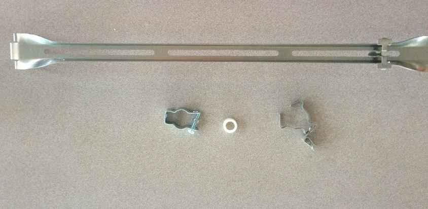

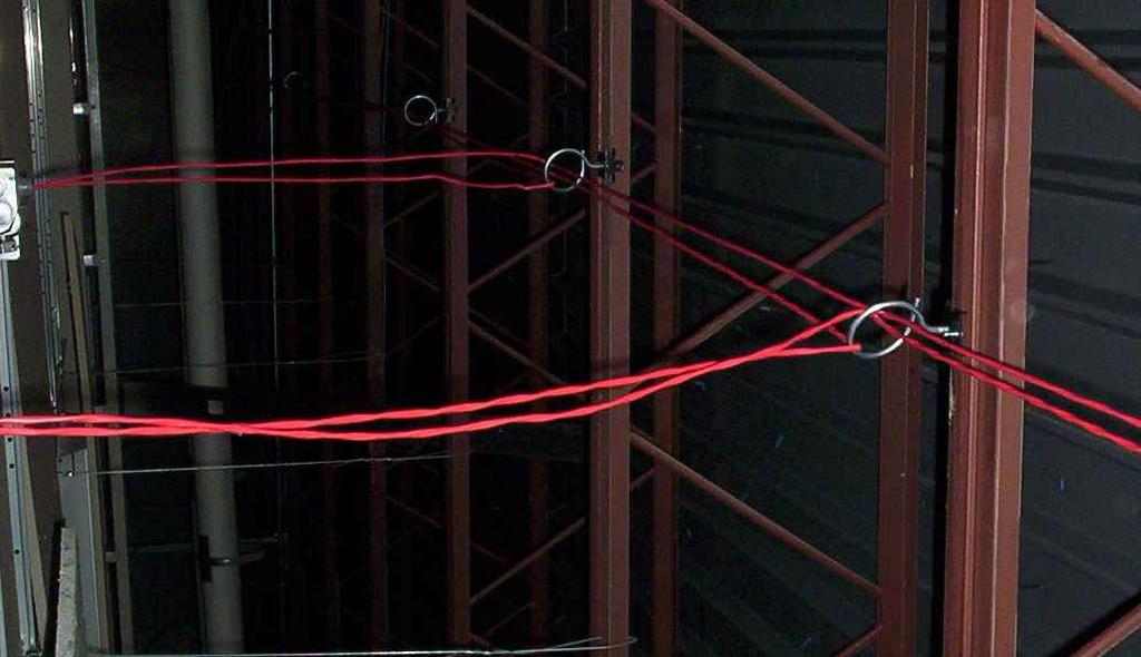
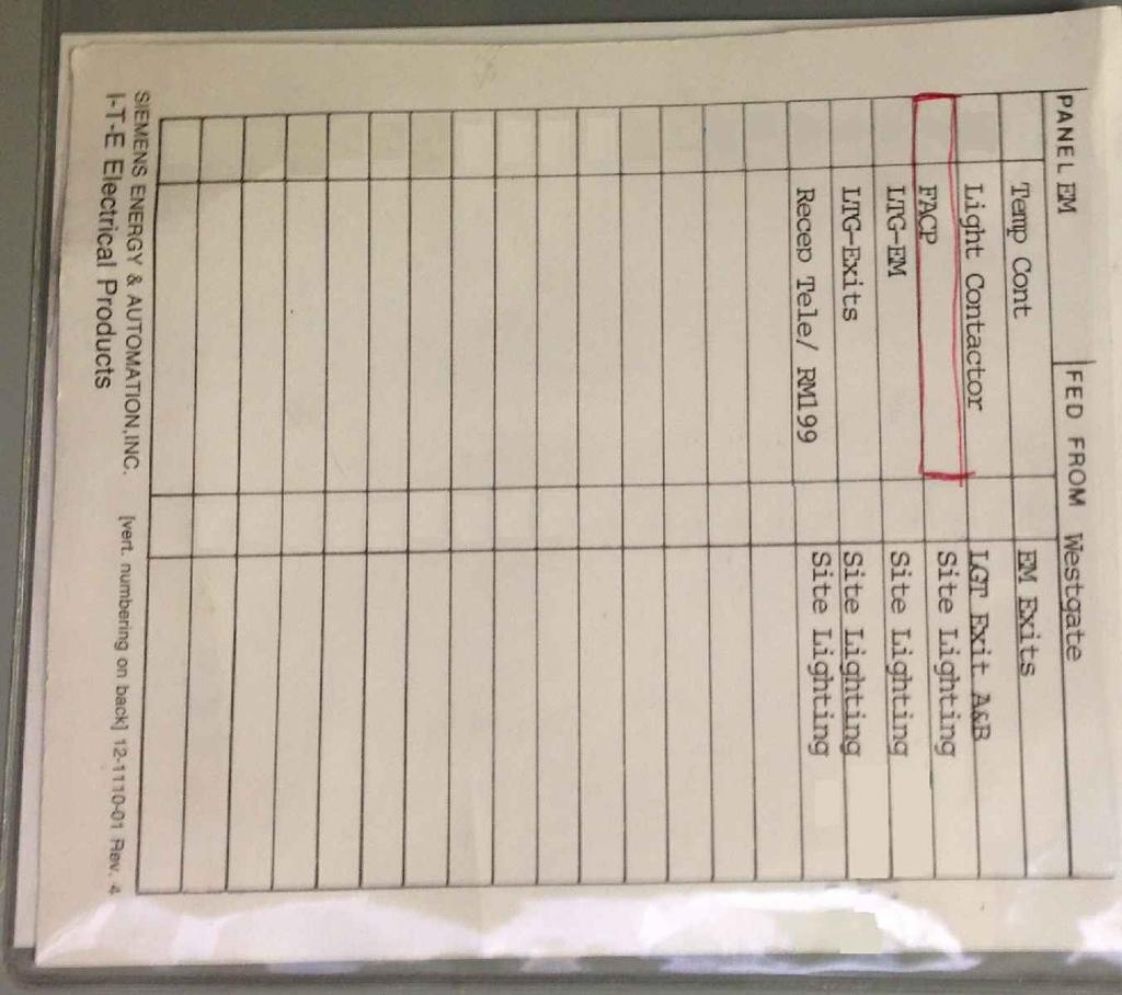
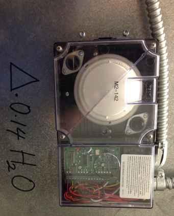
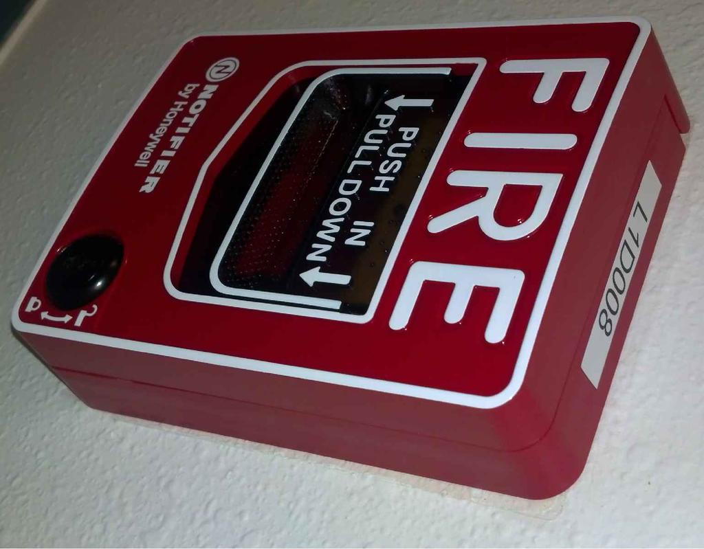
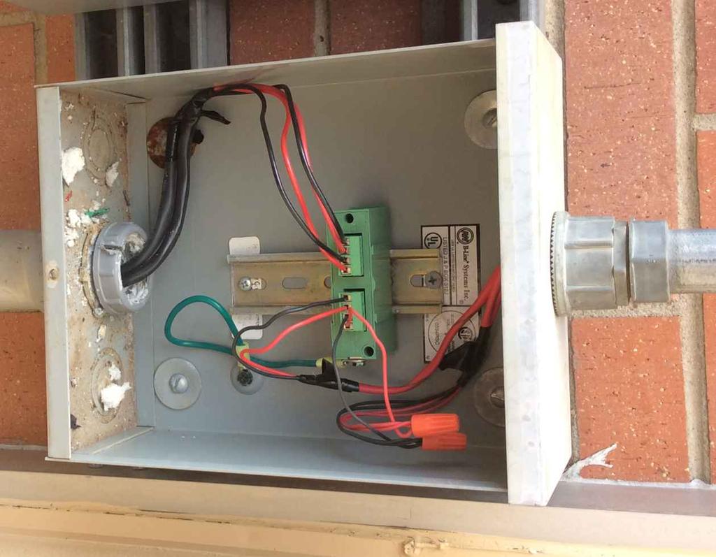
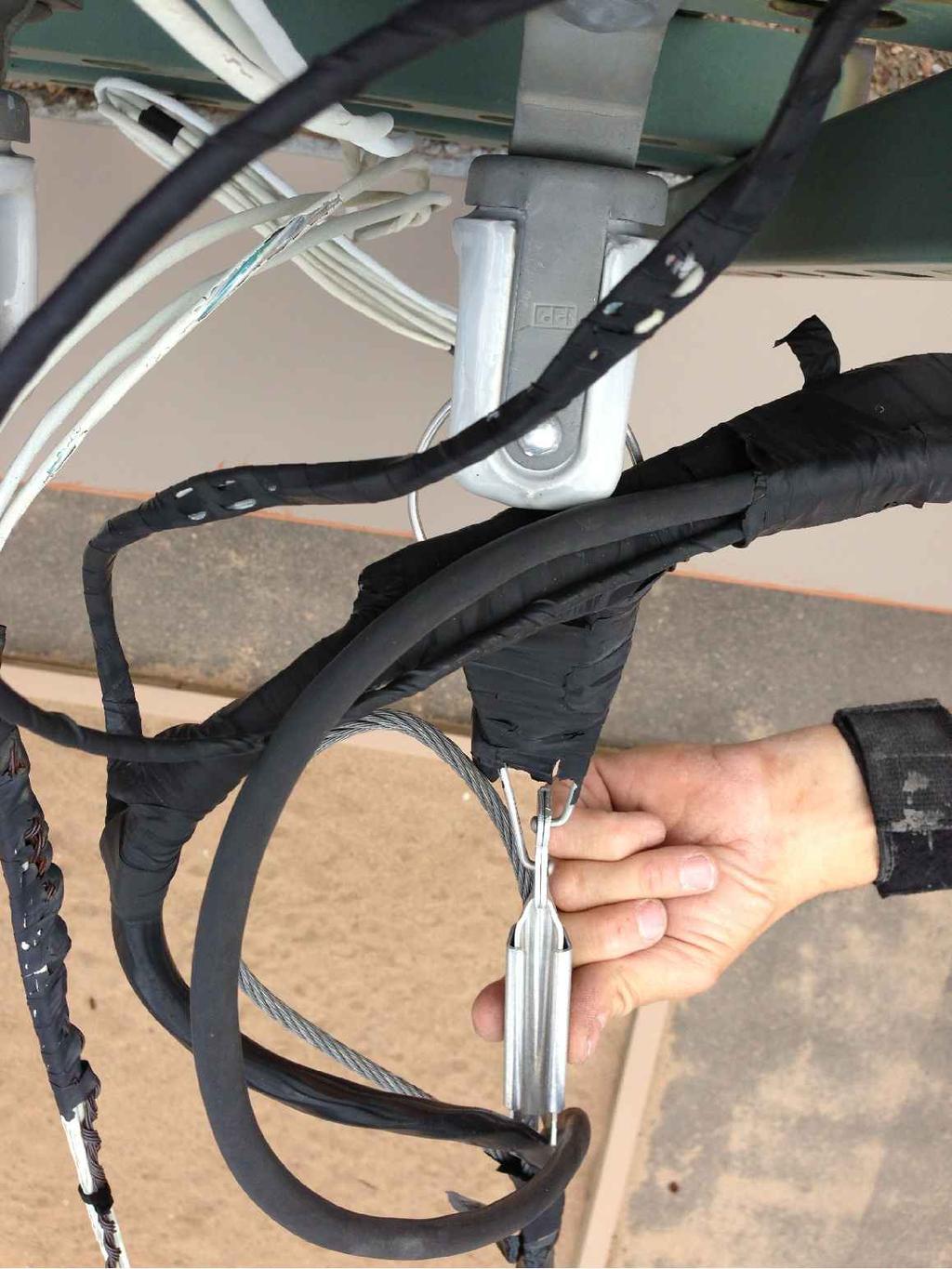
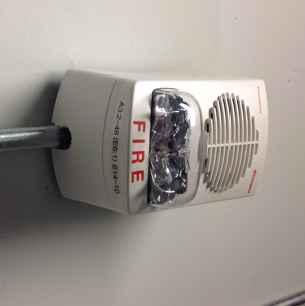
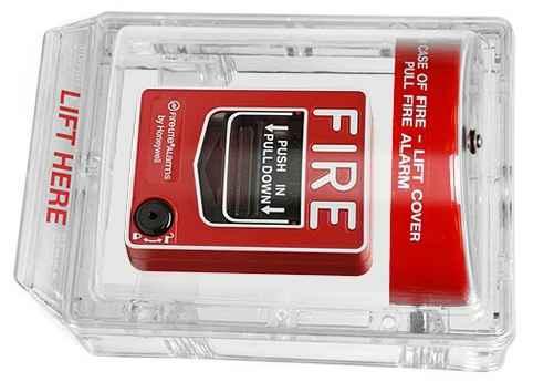
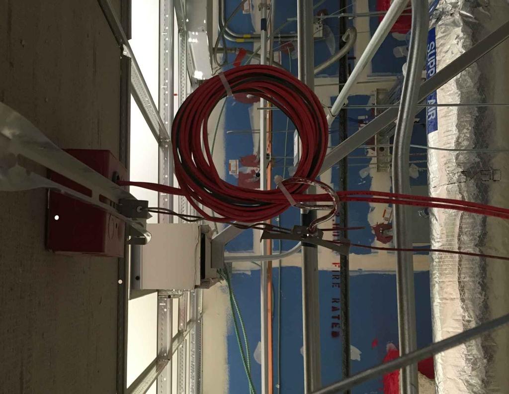

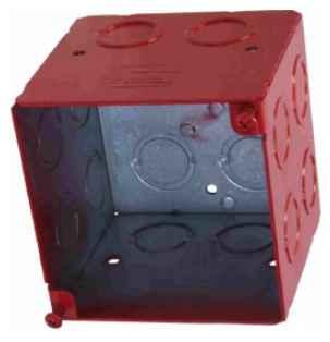


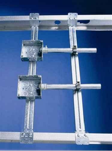


42 PROVIDETYPEDELECTRICALPANELBREAKERCIRCUITLIST. LABELEACHNOTIFICATIONAPPLIANCEWITHNOTIFICATION APPLIANCE(NAC)CIRCUITNUMBERANDDEVICENUMBERIN CIRCUIT(I.E.N1-1-1ORA1:1-1).LABELNOTIFICATION APPLIANCE(NAC)CIRCUITENDOFLINE(EOL)(NAC1:1EOL). USEKROYLETTERINGMACHINEWITH¼-INCHMINIMUM BLACKLETTERINGONWHITEBACKGROUND,UNLESS ALTERNATELABELINGISAPPROVEDBYOWNER. SELECTABLECANDELADEVICESSHALLBEINSTALLEDWITH SETTINGSASINDICATEDONCONTRACTDOCUMENTS. SIMPLEXSTROBESETTINGSSHALLBESETINFACP PROGRAMMING. PROVIDEWIREIDENTIFICATIONLABELS(N1:1,ETC.)ON WIRESENTERINGPANELSANDJ-BOXES. CONTRACTORSHALLDEMOLISHEXISTINGLABELSFOR DEMOLISHEDDEVICES NAC CIRCUIT LABELS 108. LABEL DEMOLITION BATTERIESSHALLBELABELEDWITHMONTH/YEAROF INSTALLATIONANDMONTH/YEAROFMANUFACTURE. CONTRACTORSHALLPROVIDEANDINSTALLDOORFRAME PLACARDSTOMATCHFACILITYASSESSMENT. ARCHITECT/ENGINEERSHALLDEFINEROOMSTHATREQUIRE PLACARDSONCONTRACTDOCUMENTS.THEDOORFRAME PLACARDSSHALLREFLECTTHEMAPPSROOMDESIGNATIONAND SHALLBEENGRAVEDPHENOLICLABELSMATCHINGTHECOLOROF EXISTINGDOORFRAMELABELS(UNLESSALTERNATECOLOR APPROVEDBYDISTRICT),APPROXIMATELY2 TALLBY5 WIDEAND ATTACHEDTOTHECENTEROFTHEDOORFRAME(STICKYBACK). CONTRACTORSHALLPROVIDESAMPLEDOORTAGSFOROWNER APPROVALPRIORTOINSTALLATION BREAKER LOCKS 103. BREAKER CIRCUIT LIST 104. NOTIFICATION APPLIANCE LABELS 105. SELECTABLE CANDELA 107. BATTERY LABELS 109. CONCEALED DEVICES 110. FACILITY ASSESSMENT DOOR PLACARDS CONTRACTORSHALLREUSE/REINSTALLEXISTINGUL LISTEDPULLSTATIONCOVERS.EXISTINGSOUNDER COVERSSHALLHAVEBATTERIESREMOVEDPRIORTO REINSTALLATION. NEWCOVERSSHALLBEEQUIPPEDWITH ALARMS(WITHOUTBATTERIES)ANDSHALLBEPROVIDEDIN GYMSANDCAFETERIAS. LABELEACHINITIATINGDEVICEWITHDEVICEIDADDRESS(I.E.L1-D001ORM1-001).SMOKEANDHEATDETECTORSSHALL BELABELEDONBASE. USEKROYLETTERINGMACHINEWITH¼-INCHMINIMUMBLACKLETTERINGONWHITE BACKGROUND,UNLESSALTERNATELABELINGISAPPROVEDBYOWNER. LABELDUCTDETECTORHOUSINGWITHDEVICEID ADDRESS(I.E.L1-D001ORM1-001).USEKROYLETTERING MACHINEWITH¼-INCHMINIMUMBLACKLETTERINGON WHITEBACKGROUND,UNLESSALTERNATELABELING APPROVEDBYOWNER.PROVIDEMAGNEHELIC DIFFERENTIALPRESSUREDELTAWRITTENONTHEDUCT ADJACENTTOTHEDETECTORHOUSINGWITHABLACK SHARPIEPEN.ALSODOCUMENTTHISVALUEONTHE RECORDDRAWINGS. LABELEACHREMOTEDUCTDETECTORORBEAM DETECTORTESTSTATIONWITHASSOCIATEDDEVICEID ADDRESSANDASSOCIATEDHVACUNITORBEAM DETECTORDESIGNATION(I.E.L1-D001RTU-1,L1-D004NORTH BEAM,ETC.).LABELLOCATIONOFTHEDEVICEASSOCIATED WITHTHETESTSTATION,IFTHETESTSTATIONISNOTIN THEDIRECTVICINITYOFTHEASSOCIATEDDEVICE(I.E. L1-M001RTU-1CLASSROOM201).USEKROYLETTERING MACHINEWITH¼-INCHMINIMUMBLACKLETTERINGON WHITEBACKGROUND,UNLESSALTERNATELABELINGIS APPROVEDBYOWNER. WHENPATCHINGDUCTS,UTILIZESTEELPLATESSECURED BY#8X½ INDENTEDSLOTTEDHEXWASHERHEADTYPEA SHEETMETALSCREWSANDAPPLYMASTICWHICHIS LISTEDANDLABELED 181A-M INACCORDANCEWITH UL181A.DONOTUSETAPE. CONTRACTORSHALLLABELCONDUITASSOCIATEDWITH FIREALARMCONTROLEQUIPMENTCABINETSWITHTHE CIRCUITSPRESENTINEACHCONDUIT.LABELSSHALL BE1 WHITETEXTONREDBACKGROUNDFORSILVER CONDUITOR1 BLACKTEXTONWHITEBACKGROUNDFOR REDCONDUIT.SEEEXAMPLEPICTURESATTACHED. MODULELEDVISIBLE THROUGHCOVERPLATE 111. MODULE LABELS 112. INITIATING DEVICE LABELS 113. PULL STATION COVERS 114. DUCT DETECTOR LABELS 115. REMOTE TEST SWITCHES CONDUITS,JUNCTIONBOXESANDDEVICEBACKBOXES SHALLHAVEAPPROPRIATEPLENUMRATEDPLASTICEDGE PROTECTIONWIREINSULATINGBUSHINGWHEREOPEN CABLEROUTINGOCCURS.DONOTUSEROMEXTYPE CONNECTORS. OPENCABLINGSHALLBEINSTALLEDINANEATAND WORKMANLIKEMANNER.CONTRACTORSHALLREDUCE THEQUANTITYOFTIESINUSE.CONTRACTORSHALLUTILIZE REDPLENUMRATEDTIESONLY.REPLACETIES ENCOUNTEREDDURINGCONSTRUCTIONTHATARENOT RATED. OPENCABLINGSHALLBESUPPORTEDATAMINIMUMOF EVERY4TO6FEETTOBUILDINGSTRUCTURALMEMBERS UTILIZINGMETALBRIDLERINGS.CABLINGTHATISSECURED TOSPRINKLERPIPING,HVACDUCTWORK,ELECTRICAL CONDUITOROTHERNON-STRUCTURALBUILDINGMEMBER SHALLNOTBEACCEPTABLEANDSHALLCAUSETHECABLE TOBERE-INSTALLEDANDRE-SUPPORTEDINAPROPER MANNER. ROUTECABLESSUCHTHATAMINIMUMSEPARATIONOF ½ ISMAINTAINEDBETWEENCLASS1WIREAND POWER-LIMITEDFIREALARMCIRCUITS.PROVIDESEPARATE RELAY(MR201CORAPPROVEDEQUIVALENT)WHERE 120VACISREQUIREDTORELEASEFIRE/SMOKEDAMPERS, MAGNETICDOORHOLDERS,ORSIMILAR.FORNOTIFIER DEVICES,BARRIERCB500MAYBEINSTALLEDINPLACEOF ANADDITIONALRELAY. 120VAC NAC24VDC IN OUT APPROPRIATEFIRECAULKINGORSEALANTSHALLBE UTILIZEDWHEREOPENCABLINGPENETRATESFIRE SEPARATIONBARRIERSORBUILDINGSEPARATIONWALLS OCCUR. FIRECAULKALLCONDUITENDSWHERECONDUIT SLEEVESPENETRATEFIREBARRIERSEPARATIONS,AFTER CABLEHASBEENINSTALLED DUCT DETECTOR SAMPLING TUBE PATCH METHOD 117. CONDUIT LABELS MOUNTOUTLETBOXFORELECTRICDOORHOLDERTO WITHSTAND80POUNDSPULLINGFORCE.WHEREWALL CONSTRUCTIONISWOODORSTEELFRAME,UTILIZECADDY TELESCOPICBRACKETTSGB16/TSGB24ORAPPROVED EQUIVALENTOR2X4PLYWOODSECUREDTOADJACENT SUPPORTSFORNEWCONSTRUCTION S. PIERCE STREET SUITE 205 LITTLETON, CO LABELEACHCONCEALEDDEVICELOCATIONWITHDEVICE TYPE,DEVICEIDADDRESSANDCIRCUITFUNCTION(I.E. L1D102RTU-10DUCTDETECTOR)ATTHEADJACENTCEILING TILEGRIDT-BAR.USEPLASTICLAMINATEWITHENGRAVED ¼-INCHLETTERING.LAMINATESHALLBEOFREDONWHITE CORECONSTRUCTION(WHITELETTERINGONRED BACKGROUND).CONTRACTORSHALLPROVIDESAMPLE PLACARDFOROWNERAPPROVALPRIORTOINSTALLATION FACP LABELS LABELEACHCONTROLMODULEORMONITORMODULE WITHDEVICEIDADDRESSANDFUNCTION(I.E.L1-M1AHU-1 SHUTDOWN,M1-5CLOSEFIRE/SMOKEDAMPERS,ETC.).USE KROYLETTERINGMACHINEWITH¼-INCHMINIMUMBLACK LETTERINGONWHITEBACKGROUND,UNLESSALTERNATE LABELINGISAPPROVEDBYOWNER. FIREALARMVENDOR SHALLPROVIDECOVERPLATESTHATPERMITDEVICE CONTROL/MONITORLEDVISIBILITY. TAMI LYNN HOLLEY,PE,LLC Specializing In Fire Alarm Engineering CONTRACTORSHALLPROVIDEANDINSTALLCADDY512 (BH3 FOR3.5"DEEPBACKBOX)BOXSUPPORT(OR APPROVEDEQUIVALENT). ADJUSTABLECADDYSSHALLNOT BEPERMITTED. DETAILS ARE GRAPHICAL DEPICTIONS OF DIV 28 SPECIFICATIONS PROVIDEPANELBREAKERLOCKSFORALLELECTRICAL CIRCUITSFORFIREALARMCONTROLEQUIPMENTPANELS. FIREALARMCIRCUITBREAKERLOCKSSHALLBECOLOR CODEDRED.BREAKERLOCKSSHALLBEECLIPSELOCK-FA ORAPPROVEDEQUIVALENT. CABLEROUTINGSHALLBEPERPENDICULARTOOR PARALLELTOSTRUCTURALBUILDINGMEMBERS,AND SHALLUTILIZEAMETALBRIDLERINGTYPESUPPORT SYSTEMATTACHEDTOSTRUCTURALBUILDINGMEMBERS ONLY.DIAGONALROUTINGOFCABLESHALLNOTBE CONSIDEREDACCEPTABLEANDSHALLCAUSECABLETOBE REMOVEDANDREINSTALLED.OPENCABLINGSHALLBE INSTALLEDINANEATANDWORKMANLIKEMANNER. CONTRACTORSHALLREMOVEANYKINKSORPINCHESIN CABLE. BRIDLERING TECHNICAL GUIDELINES LABELINSIDEOFFACPWITHACCOUNTINFORMATION, BYPASSZONESANDLOCATIONOFFACP120VACCIRCUIT PANELANDBREAKERNUMBER. USEKROYLETTERING MACHINEWITH¼-INCHMINIMUMBLACKLETTERINGON WHITEBACKGROUND,UNLESSALTERNATELABELINGIS APPROVEDBYOWNER MAGNETIC DOOR HOLDER SUPPORT CONDUITSHALLBESECURELYFASTENEDANDSUPPORTED ONEACHSIDEOFPENETRATION GROMET & STRAIN RELIEF BUSHING 119. PLENUM RATED TIES 120. BRIDLE RINGS VAC AND 24VDC SEPARATION 122. FIRE CAULKING OPENCABLINGSHALLBEROUTEDAWAYFROMOTHER BUILDINGCABLINGANDEQUIPMENT,ANDSHALLBE ROUTEDTOANDFROMTHEDEVICEINAVERTICALOR HORIZONTALMANNER.MAINTAINCABLINGATTHESAME LEVELWHEREPOSSIBLE,CABLINGTHATISNOTDROPPED VERTICALLYTOTHEDEVICEORROUTEDHORIZONTALLY STRAIGHTTOTHEDEVICESHALLNOTBECONSIDERED ACCEPTABLE.CABLINGTHATISROUTEDTHROUGH,OVER, UNDERORAROUNDOTHEREQUIPMENT,WHENASTRAIGHT HORIZONTALORVERTICALPATHISAVAILABLESHALLNOT BECONSIDEREDACCEPTABLEANDSHALLCAUSETHE CABLETOBEREMOVEDANDBEREINSTALLED. FOREACHDEVICE,CONTRACTORSHALLNEATLYLOOP4'OF CABLEANDSUPPORTINNEARESTBRIDLERING. TERMINATIONSBETWEENFPLPANDWETLOCATIONCABLE SHALLBEORIENTEDINAVERTICALPOSITIONTOALLEVIATE POSSIBILITYOFWATERRETENTION CONDUIT SUPPORT THROUGH PENETRATION 124. BACKBOX AND BACKBOX SUPPORT 125. CABLE ROUTING OVERHEADCONDUITENTRIESTOMODULARCLASSROOMSSHALLBEINSTALLEDWITHAWEATHERHEAD,CABLE SUPPORT,DRIPLOOPANDSTRAINRELIEF. SURGESUPPRESSORSSHALLBEPROVIDEDTOPROTECTBOTHTHESCHOOL ANDTHEFIRSTMODULARCLASSROOM. WEATHERHEAD TENSIONCABLE SHOPDRAWINGSSHALLINCLUDEFACPPROGRAMMING LISTWHICHINCLUDESDEVICENUMBER,DEVICELOCATION ANDREFERENCESTOMAJORBUILDINGAREAS. WHERE NECESSARYTODISTINGUISHTHELOCATIONSOFTWOOR MOREDETECTORS,COMPASSDIRECTIONSSHALLBE INCORPORATEDINTHEDEVICELOCATIONDESCRIPTIONIN PROGRAMMING.EXAMPLESINCLUDE: L1-D001 L1-D002 L1-D003 L1-D004 L1-D005 L1-D006 L1-D007 L1-D010 L1-D011 L1-M001 L1-M060 SMOKE(PHOTO) SMOKE(PHOTO) SMOKE(PHOTO) SMOKE(PHOTO) SMOKE(PHOTO) HEAT SUPL(DUCTP) SMOKE(BEAM) SMOKE(BEAM) PULLSTATION RELAY CLASSROOM1EAST CLASSROOM1WEST WESTCORRIDORNORTH WESTCORRIDORCENTER WESTCORRIDORSOUTH IDF200 AHU-1RETURN GYM150NORTH GYM150SOUTH NORTHENTRY 136 RTU-2SHUTDOWN PROJ. NO. JNH DRAWN: CHECKED: TLH TLH APPROVED: DATE: 12/27/ FACP PROGRAMMING LABELS DRIPLOOP FA-001 FA-002 FA-003 FA-004 FIRE ALARM UPGRADES FIREALARMSYSTEMLABELING&INSTALLATION FIREALARMSYSTEMDETAILS VESDAINSTALLATIONDETAILS VESDAINSTALLATIONDETAILSCONTINUED ISSUED FOR: BID DOCUMENTS SHEET TITLE: STRAINRELIEF FIREALARMSYSTEM LABELING& INSTALLATION SCALE: SHEET NUMBER 126. CABLE ROUTING 127. SERVICE LOOP 128. WIRE TYPE AND STRIPING 129. MODULAR CLASSROOM J-BOX 130. OVERHEAD CABLE TO MODULAR CLASSROOM 132. SHEET INDEX FA-001


, LIMITEXTENSIONBOXESTOAMAXIMUM OFONEPERDEVICEBACKBOX. INSTALLPLENUMRATEDPLASTICWIRE BUSHING.DONOTUSEROMEX CONNECTOR.")


 FIREALARM FIREALARM DEVICELOOP DEVICELOOP FROMPREVIOUS TONEXT DEVICE DEVICE FIREALARMCONTROLMODULE LABEL MODULE PROVIDEINTERPOSINGRELAYWITHCONTACT \"SECURITY GATE RATINGFORINTERCONNECTEDLOAD")
.")
43 4" LOCATECABLESUPPORTINGDEVICE NOMORETHAN2FTFROMTHE CENTERLINEOFTHEDEVICEBACKBOX LOCATESUPPORTINGDEVICE 4FT-6FTAPART 2' 4'-6' STRUCTURALBUILDING MEMBER MAP FACP CABLE SUPPORTING DEVICE BACKBOXSUPPORT FIREALARM PAGINGANDCLOCK FIREALARM DEVICE CORRIDOR FINISHED FLOOR CORRIDOR TEMPERATURECONTROL CARDACCESS 1. CABLESUPPORTINGDEVICESSHALLBEATTACHEDTOBUILDINGSTRUCTURALWALLS ORMEMBERS. 2. MAINTAINPLENUMCABLEROUTINGATHIGHESTELEVATION. 3. MAKEALLDEVICEDROPSASCLOSETOVERTICALASPOSSIBLE. 4. REFERTOOPEN(PLENUM)CABLEINSTALLATIONREQUIREMENTSINTECHNICAL GUIDELINES. RPS FINISHED FLOOR SECURITY DATA(INCL.TELEPHONE) CEILINGTILE 36"MIN FINISHED FLOOR CABLE SUPPORTINGDEVICE NEATLYLOOP4'OFCABLE ANDSUPPORTINSIDETHE NEARESTBRIDLERING DEVICE BACKBOX FLOOR FLOOR CROSSSECTION LONGITUDINALSECTION 201. FIRE ALARM ANNUNCIATOR PANEL ELEVATION 202. FIRE ALARM CONTROL PANEL ELEVATION 203. BOOSTER POWER SUPPLY PANEL ELEVATION 204. TYPICAL PLENUM CABLE WIRING INSTALLATION 205. BRIDLE RING SUPPORT AND SYSTEM SEPARATION BRIDLERING SUSPENSIONWIRE EXTENSIONBOX,WHENREQUIRED. ONNEWCONSTRUCTION.DONOT USEEXTENSIONRINGSONRETROFIT APPLICATIONS(SPEAKERSEXCLUDED), LIMITEXTENSIONBOXESTOAMAXIMUM OFONEPERDEVICEBACKBOX. INSTALLPLENUMRATEDPLASTICWIRE BUSHING.DONOTUSEROMEX CONNECTOR. PLENUMCABLE EMTRACEWAY,SIZESUCHTHAT CABLEFILLDOESNOTEXCEED40%. CEILINGTILE NEATLYLOOP4'OFCABLE ANDSUPPORTINSIDE BRIDLERINGWITHIN12" OFDEVICEBACKBOX. REFERENCEDETAIL204. ROOF DECK BRIDLERINGAND MULTIFUNCTONCLIP WALL TYPICALWALLMOUNTED DEVICE. TRIMRING, WHENREQUIRED PLENUM CABLE PLENUMCABLE CABLE SUPPORTINGDEVICE PLENUMCABLE CABLE SUPPORTING DEVICE ELECTRICAL METALLICTUBING HVACDUCTWORKOROTHER BUILDINGOBSTRUCTIONTHAT INTERFERESWITHPLENUM CABLEROUTING INSTALLPLENUM RATEDPLASTIC WIREBUSHING. DONOTUSE ROMEXCONNECTOR. INSTALLPLENUMRATED PLASTICWIREBUSHING. DONOTUSEROMEX CONNECTOR. INSTALLPLENUMRATED PLASTICWIREBUSHING. DONOTUSE ROMEXCONNECTOR. ATFIRESEPARATIONBARRIERSONLY: FIRECAULKSLEEVEPENETRATIONS ANDCABLEOPENINGSWHENFIRE SEPARATIONBARRIERISPENETRATED. ACTIVATESECURITYGATEMODULEUPONACTIVATIONOFNEARESTCORRIDOR DETECTORONLY. FIREALARMSMOKE DETECTOR(TYP.) FIREALARM FIREALARM DEVICELOOP DEVICELOOP FROMPREVIOUS TONEXT DEVICE DEVICE FIREALARMCONTROLMODULE LABEL MODULE PROVIDEINTERPOSINGRELAYWITHCONTACT "SECURITY GATE RATINGFORINTERCONNECTEDLOAD (FUTURE)" (ASREQUIRED). TO120VAC 120VACSECURITYGATE LOCALPOWER WALLORFIRERATED SEPARATIONBARRIER 208. RACEWAYS INSTALLED UNDER ROOF DECKING PROVIDEANDINSTALLONEMODULEPERDEVICE(EXCEPTBACKFLOW PREVENTERTAMPERS). (2/C#16PLENUM) WATERFLOW SWITCH (BYFIRE PROTECTION CONTRACTOR) TAMPERSWITCH (BYFIRE PROTECTION CONTRACTOR) (2/C#16PLENUM) FROM PREVIOUS DEVICE DV FROM PREVIOUS DEVICE WHEREEXISTINGELEVATORISNOTCAPABLEOF FUNCTIONALITYAS DEPICTEDBELOW,CONTRACTORSHALLPROVIDEANDINSTALL MODULESANDLABELFORFUTUREUSE TYPICAL DELUGE VALVE CIRCUIT (2/C#16PLENUM) PROJECTEDREFLECTORTYPE BEAMSMOKEDETECTOR REFLECTOR COVERSREQUIREDFORALLDEVICESINGYMNASIUM INCLUDINGMODULES. PROJECTEDBEAMSMOKE DETECTORTRANSMITTER 2/C#16PLENUM BEAMDETECTORREMOTEALARM/TESTSTATION.LOCATE ALARM/TESTSTATIONAMINIMUMOF8FTABOVEFINISHED FLOOR(ACCESSIBLEFROM6FTLADDER). FROM PREVIOUS DEVICE TONEXT DEVICE FROMPREVIOUSDEVICE FIREALARM DEVICELOOP FIRE ALARM DEVICE LOOP 212. TYPICAL FIRE SEPARATION BARRIER CIRCUIT 213. TYPICAL WATERFLOW AND TAMPER SWITCH CIRCUIT TONEXT DEVICE ELEVATOR LOBBYSMOKE DETECTORS ELEVATOR SHUNTTRIP ELEVATORTOP OFSHAFTSMOKE DETECTOR ELEVATOR MACHINE ROOMSMOKE DETECTOR ELEVATOR SHUNTTRIP POWER SUPERVISION 216. BEAM SMOKE DETECTOR CIRCUIT WITH TIMED OVERRIDE 4"C.2/C#16TW CABLE 217. ELEVATOR SHUNT TRIP CONTROL CIRCUIT TUBESUPPORTHOLEONLYFOR DUCTSMORETHAN3'WIDE HVACUNITMOTOR(WIRE MOTORPOWERONSOTHAT HVACUNITSHUTSDOWN OCCURS UPONLOSSOF POWERTOMOTOR) FORHVACUNITGREATER THAN2,000CFMMOUNTDUCT DETECTOR INRETURNSIDE OFHVACUNIT PERIMC REQUIREMENTS FROMPREVIOUS DEVICE (4/C#18PLENUM) MAINTAINBAS STATUS CONNECTION RTU ~ FIREALARMCONTROLMODULE PROVIDEINTERPOSINGRELAYWITH CONTACTRATINGFOR INTERCONNECTEDLOAD(AS REQUIRED) TONEXTDEVICE FIREALARM DEVICELOOP ELEVATORMACHINEROOMFIXED TEMPERATUREHEATDETECTOR. HEATDETECTORSSHALLBE INSTALLEDWITHIN2'OFEACH MACHINEROOMSPRINKLERHEAD DEVICE FIREALARMREMOTEDUCT DETECTORTESTSTATION.LOCATE TESTSTATIONINNEAREST CORRIDORLOCATIONAMINIMUM OF 8FTABOVETHEFINISHED FLOORORINTHECEILINGTILE (ACCESSIBLEFROM6FTLADDER). 4"C.2/C#16TW CABLE 3 TO120VACPOWER, ASREQUIRED 215. TYPICAL KITCHEN HOOD CIRCUIT 3 TONEXT DEVICE KEYEDMANUALOVERRIDESWITCH. TROUBLECONDITION SHALLACTIVATEIFKEYEDOVERRIDEISACTIVEFORMORE THAN4HOURS. KEYEDMANUALOVERRIDESWITCHSHALL ONLYBEPROVIDEDINGYMSANDAUDITORIUMSWHEN APPROVEDBYFRCCPROJECTMANAGER. 4"C.2/C#16TW CABLE 4/C #18 PLENUM FIREALARM MONITORMODULE TAMPERSWITCH (BYFIRE PROTECTION CONTRACTOR) 3 ALTERNATE FLOORRECALL 2/C#16PLENUM FIREALARMDEVICELOOP TONEXT DEVICE FIREALARMCONTROLMODULE PROVIDEINTERPOSINGRELAYWITHCONTACT RATINGFORINTERCONNECTEDLOAD (ASREQUIRED) 120VACFIRESHUTTER, WONDOOR,ORFIRE SEPARATIONBARRIER ELEVATORTOPOFSHAFTFIXED TEMPERATUREHEATDETECTOR. HEATDETECTORSSHALLBE INSTALLEDWITHIN2'OFEACHTOP OFSHAFTSPRINKLERHEAD PRIMARY FLOORRECALL 24VDCPOWER KITCHENHOODEXTINGUISHING SYSTEMCONTROLPANEL(BY FIREPROTECTIONCONTRACTOR) FIREALARMSMOKE DETECTOR(TYP.) FIREFIGHTER HATLIGHT TONEW DEVICE 211. TYPICAL SECURITY GATE CIRCUIT ACTIVATEMODULEUPONACTIVATIONOFNEARESTCORRIDORDETECTORONLY TYPICAL PLENUM CABLE INSTALLATION THROUGH PENETRATION FIREALARM MONITORMODULE FIREALARM DEVICELOOP FIREALARM DEVICELOOP CIRCUIT TO NEXT DEVICE 209. TYPICAL PLENUM CABLE WIRE INSTALLATION WITH OBSTRUCTION DELUGEVALVE(BY FIREPROTECTION CONTRACTOR) MAINTAINBASSTATUS CONNECTION FIRECAULKSLEEVE PENETRATIONSANDCABLE OPENINGSWHENFIRE SEPARATIONBARRIERIS PENETRATED. SMOKEORHEATDETECTOR 207. TYPICAL CEILING MOUNT DEVICE INSTALLATION FROMPREVIOUS DEVICE TO120VAC LOCALPOWER STRUCTURAL BUILDINGMEMBER MINICONDUIT HANGERS TRIMRING,WHENREQUIRED SMOKEORHEAT DETECTORTRIMRING EMTRACEWAY,SIZESUCH THATCABLEFILLDOES NOTEXCEED40%. CABLE SUPPORTING DEVICE INSTALLPLENUMRATED PLASTICWIREBUSHING.DO NOTUSEROMEXCONNECTOR TYPICAL WALL MOUNT DEVICE INSTALLATION FIREALARM DEVICELOOP STRUCTURAL BUILDING MEMBER ALLTHREADOROTHERAPPROVED CABLESUPPORTINGDEVICE STRUCTURAL BUILDINGMEMBER CABLE SUPPORTING DEVICE CONDUITSUPPORTSTRAP OROTHERDISTRICT APPROVEDRACEWAY SUPPORTING DEVICE PLENUMCABLE CEILINGTILE EXTENSIONBOX,WHENREQUIRED. ONNEWCONSTRUCTION.DONOT USEEXTENSIONRINGSON RETROFITAPPLICATIONS (SPEAKERSEXCLUDED),LIMIT EXTENSIONBOXESTOAMAXIMUM OFONEPERDEVICEBACKBOX. ROOF DECK PLENUM CABLE PLENUMCABLE ORCONDUIT DEVICEBACKBOX,SIZE SUCHTHATBOXFILLDOES NOTEXCEED40%. INSTALLPLENUMRATEDPLASTIC WIREBUSHING.DONOTUSE ROMEXCONNECTOR. STRUCTURAL BUILDINGMEMBER FIXEDPOSITIONBAR HANGER.DONOTUSE ADJUSTABLEHEIGHT SUPPORTS DEVICEBACKBOX,SIZE SUCHTHATBOXFILLDOES NOTEXCEED40%. ROOF DECK 1-1/2"MIN NEATLYLOOP4'OFCABLE ANDSUPPORTINSIDETHE NEARESTBRIDLERING. REFERENCEDETAIL204. CABLEORRACEWAY-TYPEWIRINGMETHOD,INSTALLEDIN EXPOSEDORCONCEALEDLOCATIONSUNDER METAL-CORRUGATEDSHEETROOFDECKING,SHALLBEINSTALLED ANDSUPPORTEDSOTHENEARESTOUTSIDESURFACEOFTHE CABLEORRACEWAYISNOTLESSTHAN1-1/2"FROMTHENEAREST SURFACEOFTHEROOFDECKING(NEC300.4E) S. PIERCE STREET SUITE 205 LITTLETON, CO CEILING CEILING 72"MAX MAP 36"MIN 72"MAX CAB TAMI LYNN HOLLEY,PE,LLC Specializing In Fire Alarm Engineering tami@holleyfpe.com WALL FAA STRUCTURE DETAILS ARE GRAPHICAL DEPICTIONS OF DIV 28 SPECIFICATIONS 60" RPS STRUCTURE SUSPENSIONWIRETO STRUCTURALMEMBER FIREALARMCONTROL MODULEFORAUDIBLE CONDITIONSIGNAL FIREALARMMONITOR MODULEFORPOWER SUPPLY TROUBLECONDITION (LOCATEINSIDE PANEL) 4'-0" TO 6'-0" TECHNICAL GUIDELINES 4"-8" 12" MINIMUM BETWEEN SYSTEMS 2' WALL FIREALARMCONTROL MODULEFORVISUAL SIGNALCONDITION AIRFLOWDIRECTION INSERTRUBBER PLUGTHISEND OFINLETTUBE. INLETTUBE HOLESFACE UPSTREAMOF AIRFLOW. RETURNTUBESLANTCUT FACEORIENTEDDOWNSTREAM OFAIRFLOW.DONOTINSERT RUBBERPLUG. 2/C#16PLENUM(SLC) DEVICE DESCRIPTION FACP FIREALARMCONTROLPANEL AUTOMATICSPRINKLERWATERFLOWSWITCH PROJ. NO. AMP AMPLIFIER AUTOMATICSPRINKLERTAMPERSWITCH DRAWN: CAB RECORDDRAWINGCABINET CHECKED: FAA FIREALARMANNUNCIATOR SPEAKER/STROBE,CEILING,CANDELA INTENSITY,WATTS RPS REMOTEPOWERSUPPLY DACT DIGITALALARMCOMMUNICATOR-POINTCONTACTID MAP GRAPHICMAP 120VACFROMELECTRICALPANEL 120VACTODAMPER,DOOR HOLDER,OROTHER120VAC DEVICE 2/C#16PLENUM(IDC) TOREMOTETESTSWITCH TOBAS(MAINTAINSTATUSMONITORING) DESCRIPTION UTILIZESEPARATEHEAVYDUTYRELAYFORFIRE ALARMINTERFACEWITH120VACTOMINIMIZE INDUCTIONONSIGNALINGLINECIRCUIT. PROVIDEMAGNEHELICDIFFERENTIALPRESSUREDELTA WRITTENONTHEDUCTADJACENTTOTHEDETECTOR HOUSINGWITHABLACKPERMANENTMARKER. SPEAKER/STROBE,WALL,CANDELA INTENSITY,WATTS S HORN/STROBE,WALL,CANDELAINTENSITY PHOTOELECTRICSMOKEDETECTOR,INTELLIGENT STROBE,CEILING,CANDELAINTENSITY FIXEDTEMP190 HEATDETECTOR,INTELLIGENT STROBE,WALL,CANDELAINTENSITY FIXEDTEMP135 HEATDETECTOR,INTELLIGENT WEATHERPROOFDEVICE RATEOFRISE135 HEATDETECTOR,INTELLIGENT WIREGUARD REMOTETESTSTATION FIRE/SMOKEDAMPER KEYEDOVERRIDESWITCH KITCHENANSULSYSTEM PHOTOELECTRICDUCTSMOKEDETECTOR,INTELLIGENT, HI-FLOORLOW-FLO MAGNETICDOORHOLDER-NEW FIREDEPARTMENTCONNECTION HEAVYDUTYRELAY DATA(REFERTODIVISION270000) OUTPUTMODULE,INTELLIGENT PHONELINEDACT SINGLEINPUTMODULE,INTELLIGENT TRANSIENTSUPPRESSION 218. TYPICAL DUCT DETECTOR AND HVAC UNIT CONTROL CIRCUIT 219. TYPICAL RETURN DUCT SMOKE DETECTOR INLET TUBE ORIENTATION 220. TYPICAL HEAVY DUTY RELAY 221. NFPA 170 COMPLIANT SYMBOLS JNH TLH TLH APPROVED: DATE: 12/27/2018 SPEAKER,WATTS MANUALPULLSTATION,DOUBLEACTION,INTELLIGENTW/KEY - FIRE ALARM UPGRADES ISSUED FOR: BID DOCUMENTS SHEET TITLE: FIREALARMSYSTEM DETAILS SCALE: SHEET NUMBER FA-002
SECTION DIGITAL, ADDRESSABLE FIRE-ALARM SYSTEM
 SECTION 283111 - DIGITAL, ADDRESSABLE FIRE-ALARM SYSTEM PART 1 - GENERAL 1.1 RELATED DOCUMENTS A. Drawings and general provisions of the Contract, including General and Supplementary Conditions and Division
1. Floor above/floor below notification. 2. Private alarm notification. 3. Not Used 4. Voice alarm notification. 5. Not Used.
 PART 1 GENERAL 1.01 Scope of Standard A. This Standard is intended to assure that fire alarm and signaling systems at Sam Houston State University provide the highest level of life safety possible. This
TABLE OF CONTENTS GENERAL... 2 A. DEFINITIONS DIGITAL, ADDRESSABLE FIRE ALARM SYSTEM... 2
 Division 28 ELECTRONIC SAFETY AND SECURITY TABLE OF CONTENTS 28 0000 GENERAL... 2 A. DEFINITIONS...2 28 3111 DIGITAL, ADDRESSABLE FIRE ALARM SYSTEM... 2 A. DESIGN REQUIREMENTS...2 B. CONSTRUCTION REQUIREMENTS...2
The following information shall become and form part of the contract documents.
 October 4, 206 To: Attention: Re: All Bidders All Bidders JCBE Gymnasium HVAC Upgrades BC#: 206433 Edmonds Project No.: BHM6090 All bidders, The following information shall become and form part of the
SECTION INTRUSION DETECTION
 (NOTE TO DESIGNER: These Specifications are basic minimum criteria to be met in preparing the final specifications for this section, which is the responsibility of the Designer.) SECTION 28 16 00 INTRUSION
PWGSC Ontario MULTIPLEX FIRE ALARM SYSTEM Sect Region Project Page 1 Number R
 Region Project Page 1 PART 1 - GENERAL 1.1 REFERENCES.1 CAN/ULC-S524-2006, Standard for the Installation of Fire Alarm Systems..2 CAN/ULC-S525-2007, Audible Signal Device for Fire Alarm Systems..3 CAN/ULC-S526-2007,
SECTION FIRE ALARM SYSTEMS
 SECTION 28 3100 PART 1 -GENERAL 1.01 RELATED DOCUMENTS Drawings and general provisions of the Contract, including General and Supplementary Conditions and Division 1 Specification Sections, apply to this
Smoke Detector Activation of any smoke detector shall start the alarm verification mode.
 Description: The purpose of the section is to provide the UMCP Design Standards for the design and implementation of Fire Alarm Systems at the UMCP campus. Related Sections: TBD Effective Date: July 10,
SECTION INTRUSION DETECTION SYSTEM
 SECTION 13845 INTRUSION DETECTION SYSTEM PART 1 GENERAL 1.01 SUMMARY A. Section Includes: A complete, operable, tested intrusion detection system, bearing Underwriters Laboratories (UL) mercantile listing
COUNTY OF KINGS KINGS COUNTY JAIL EXPANSION PHASE III
 SECTION 28 3111 - DIGITAL ADDRESSABLE FIRE ALARM SYSTEM PART 1 - GENERAL 1.1 RELATED DOCUMENTS A. General provisions of the Contract, including General and Supplementary Conditions and Division 1 Specification
DIVISION 26 ELECTRICAL SECTION FIRE ALARM SYSTEM
 DIVISION 26 ELECTRICAL SECTION 26 81 11 PART 1 GENERAL 1.01 DESCRIPTION A. Furnish and install all equipment and accessories for a complete local, analog addressable, manually and automatically actuated,
OKLAHOMA STATE UNIVERSITY
 ENVIRONMENTAL HEALTH & SAFETY ADDRESSABLE FIRE ALARM SYSTEM STANDARD Revised 6/15 Revised: 6/15 Contact(s) Implementation Date Comments Gerald Petre, EHS June 2016 Review and Update Page 1 1.1 GENERAL
SPECIFICATION MICROMIST FIRE SUPPRESSION SYSTEM WITH SHP-PRO CONTROL PANEL
 SECTION 1 - GENERAL CONDITIONS I. SCOPE: This specification outlines the requirements for a Fike Micromist Water Mist Fire Suppression System with automatic detection and control. The work described in
2. HVAC and smoke control systems; fire, smoke, and combination fire/smoke dampers. 5. Central control and monitoring system.
 PART 1 GENERAL 1.01 Scope of Standard A. This Standard is intended to assure that fire detection/alarm systems at The University of Texas at Austin provide the highest level of fire safety possible.. This
1.3 REFERENCE STANDARDS
 SECTION 28 4600 FIRE DETECTION AND ALARM PART 1 -GENERAL 1.1 SECTION INCLUDES A. Fire alarm system design and installation, including all components, wiring, and conduit. B. Circuits from protected premises
SECTION FIRE ALARM STANDARDS REVISED CONSTRUCTION STANDARD
 PART 1 - GENERAL PURPOSE This Standard is intended to assure that fire detection/alarm systems at The University of Texas at Austin provide the highest level of fire safety possible. SCOPE This standard
B. Configuration of system shall be through Schneider Electric in Homewood, Illinois (Jerry Lanfear ).
.") SECTION 28 13 00 - ACCESS CONTROL PART I - GENERAL 1.1 SUMMARY A. This specification section describes the furnishing, installation, commissioning, and programming of a complete, turnkey, hardwired Andover
SECTION 28 13 00 - ACCESS CONTROL PART I - GENERAL 1.1 SUMMARY A. This specification section describes the furnishing, installation, commissioning, and programming of a complete, turnkey, hardwired Andover
Hinesville First United Methodist Church SECTION DIGITAL, ADDRESSABLE FIRE-ALARM SYSTEM
 SECTION 28 3111 DIGITAL, ADDRESSABLE FIRE-ALARM SYSTEM PART 1 - GENERAL 1.01 SUMMARY A. Section Includes: 1. Fire-alarm control unit. 2. Manual fire-alarm boxes. 3. System smoke detectors. 4. Heat detectors.
SECTION : FIRE ALARM & DETECTION SYSTEMS
 SECTION 28 31 10: FIRE ALARM & DETECTION SYSTEMS 1. GENERAL A. This section applies to fire detection/alarm system and carbon monoxide system components and equipment installed during new construction
FIRE & LIFE SAFTEY STANDARD
 Title: Effective Date: 01/01/14 Revised Date: 1/1/14 Code References: Title 16, Chapter 16.16 of the Roseville Municipal Code, NFPA 72 Note: This standard is a summary of Fire Department clarifications
Fire Alarm Acceptance Testing & On-Going Maintenance with The Joint Comm. Standards / Reporting. Prepared Especially for : OSFM TEC 2016
 Fire Alarm Acceptance Testing & On-Going Maintenance with The Joint Comm. Standards / Reporting Prepared Especially for : OSFM TEC 2016 Acceptance Testing 11-2008 Agenda Before you begin Completing the
MANUAL OF DESIGN CRITERIA AND SPECIFICATIONS FOR FIRE DETECTION AND ALARM SYSTEMS PUBLIC SCHOOLS IN NEW MEXICO
 MANUAL OF DESIGN CRITERIA AND SPECIFICATIONS FOR FIRE DETECTION AND ALARM SYSTEMS PUBLIC SCHOOLS IN NEW MEXICO Prepared For: Public Schools Facilities Authority State of New Mexico 2019 Galisteo, Suite
DIVISION 28 ELECTRONIC SAFETY AND SECURITY
 281300 - ACCESS CONTROL A. General DIVISION 28 ELECTRONIC SAFETY AND SECURITY At the beginning of the project, schedule a meeting with the Facilities Access/Maintenance Coordinator with questions and concerns.
Architect s Project Number of 12 Fire Alarm/Smoke Detection Systems District Master Specs 2013 Edition
 PART 1 GENERAL 1.1 SECTION INCLUDES SECTION 28 31 00 FIRE ALARM AND SMOKE DETECTION SYSTEMS A. Fire alarm and smoke detection systems 1.2 REFERENCES A. NFPA 72 B. NFPA 101 1.3 REGULATORY REQUIREMENTS A.
Environmental Health & Safety
 Environmental Health & Safety Oklahoma State University ADDRESSABLE FIRE ALARM SYSTEM STANDARD Environmental Health and Safety University Health Services Suite 002 Stillwater, OK 74078 (405) 744-7241 www.ehs.okstate.edu
Michigan State University Construction Standards FIRE DETECTION AND ALARM PAGE
 PAGE 283100-1 SECTION 283100 - DIGITAL, ADDRESSABLE FIRE-ALARM SYSTEM PART 1 - GENERAL 1.1 RELATED DOCUMENTS A. Drawings and general provisions of the Contract, including General and Supplementary Conditions
OSU PROJECT NO PAGE 1 02 NOV 2006 SECTION FIRE ALARM SYSTEM
 OSU PROJECT NO. 30-04-15 PAGE 1 PART 1 GENERAL 1.1 WORK INCLUDED A. Provide all labor, materials, and equipment required to provide a complete and operating system of manual and automatic detection devices,
SECTION FIRE ALARM SYSTEMS
 SECTION 16721 FIRE ALARM SYSTEMS PART 1 - GENERAL 1.01 RELATED DOCUMENTS A. The general provisions of the contract including General and Special Conditions and General Requirements shall apply to all work
SECTION FIRE ALARM AND SMOKE DETECTION SYSTEMS
 PART 1 GENERAL 1.1 SECTION INCLUDES A. Fire alarm and smoke detection systems 1.2 REFERENCES A. NFPA 72 B. NFPA 101 1.3 REGULATORY REQUIREMENTS A. System: UL listed B. Conform to requirements of NFPA 101
Full Service Central Station Fire Alarm Listing Evaluation
 Full Service Central Station Fire Alarm Listing Evaluation Listing Evaluation A UL Listing project includes: 1. Evaluating the central station facility for compliance with UL 827, Central-Station Alarm
Bold items are particular to the City of Euless
 EULESS FIRE DEPARTMENT FIRE MARSHAL S OFFICE INFORMATION LINE: Revised 8/2004 Fire Chief Lee Koontz Fire Marshal Paul Smith EFD-FMO 3-1 2003 International Fire & Building Code as Amended NFPA Standards
Concerns: Affects: Dated: June 12, SECTION 1: GENERAL Scope Work Included... 3
 Technical Service Note Detection Systems, Inc. Fairport, New York 14450-9199 Technical Service (800) 374-7454 Sales: (800) 289-0096 and (585) 223-4060 Fax: (585) 223-9180 Concerns: Affects: Dated: June
MOBILE FIRE - RESCUE DEPARTMENT FIRE CODE ADMINISTRATION
 MOBILE FIRE - RESCUE DEPARTMENT FIRE CODE ADMINISTRATION Fire Alarm System Plan Review 2009 International Fire Code and 2010 NFPA 72 Date of Review // BLD201 - Project Address: Project Name: _ Professional
SANTA ROSA FIRE DEPARTMENT FIRE PREVENTION BUREAU PLAN REVIEW CHECKLIST FIRE ALARM SYSTEM INSTALLATION
 July 1, 2010 SANTA ROSA FIRE DEPARTMENT FIRE PREVENTION BUREAU PLAN REVIEW CHECKLIST FIRE ALARM SYSTEM INSTALLATION Address: Permit #: Inspector: Date: Status: Inspector: Date: Status: A-Approved; AC-Approved
Moreno Valley Fire Department Fire Prevention Bureau. New and Existing Fire Alarm & Signaling Systems Guideline
 Moreno Valley Fire Department Guideline Approved and Authorized By: Adria Reinertson, Fire Marshal Issued: May 8, 2017 Alarm & Signaling Systems PURPOSE Fire alarm and signaling systems are designed to
FIRE DETECTION SYSTEM SPECIFICATION FOR MODEL XR200
 FIRE DETECTION SYSTEM SPECIFICATION FOR MODEL XR200 1.0 General 1.1 Manufacturer Manufacturer of the Fire Alarm Control Panel (FACP) equipment shall be: Digital Monitoring Products, Incorporated 2500 N.
DIGITAL, ADDRESSABLE FIRE ALARM SYSTEM
 SECTION 283111 - DIGITAL, ADDRESSABLE FIRE-ALARM SYSTEM PART 1 - GENERAL 1.1 RELATED DOCUMENTS A. Drawings and general provisions of the Contract, including General and Supplementary Conditions and Division
Fire Alarm System Fundamentals
 Fire Alarm System Fundamentals Mircom is the largest and oldest privately owned fire alarm and life safety manufacturer in North America and 5th largest overall with 50 years of industry experience. Mircom
FIRE ALARM SYSTEM 1.1 GENERAL REQUIREMENTS
 VALOUR COMMUNITY CENTRE FIRE ALARM SYSTEM Section 28 00 00 GYMNASIUM ADDITION & RENOVATION Page 1 of 3 28 00 00 FIRE ALARM SYSTEM 1.1 GENERAL REQUIREMENTS 1.2 SCOPE 1. The specification covering the General
Brighton Area Fire Authority
 615 W. Grand River Ave. Brighton, MI 48116 o: 810-229-6640 f: 810-229-1619 January 14, 2019 Fire Alarm Contractors RE: Fire Alarm Credential & Submittal Requirements To Whom It May Concern: The following
SPECIFICATION MICROMIST FIRE SUPPRESSION SYSTEM WITH CHEETAH Xi 50 CONTROL PANEL
 SECTION 1 - GENERAL CONDITIONS I. SCOPE: This specification outlines the requirements for a Fike Micromist Water Mist Fire Suppression System with a Cheetah Xi 50 addressable detection and control system.
SECTION ADDRESSABLE FIRE ALARM SYSTEM
 SECTION 16723 ADDRESSABLE FIRE ALARM SYSTEM 1 PART 1 GENERAL 1.1 DESCRIPTION A. This section outlines the requirements for the installation, programming and configuration of Addressable Fire Alarm System
Standard of Practice - Fire Alarm Systems. NOTE: Significant revisions or additions to the previous standards are highlighted in italics.
 A28.1 Standard of Practice - Fire Alarm Systems NOTE: Significant revisions or additions to the previous standards are highlighted in italics. OBJECTIVE OF STANDARD To provide compliant smart addressable
Addressable Fire Alarm Control Panel
 PRODUCT SPECIFICATION XR2400F Addressable FACP Addressable Fire Alarm Control Panel Description The DMP XR2400F Addressable Fire Alarm Control Panel is an expandable Fire Alarm Control with built-in DACT
SECTION WET-PIPE SPRINKLER SYSTEMS
 SECTION 21 13 13 WET-PIPE SPRINKLER SYSTEMS PART 1 - GENERAL 1.1 SCOPE OF WORK A. Design, installation and testing shall be in accordance with NFPA 13 except for specified exceptions. B. The demolition
DONALD H. BERG, ARCHITECT
 DONALD H. BERG, ARCHITECT DVA PROJECT 632-CSI-402 PET/CT ROOM #A0-10 RENOVATION BASEMENT LEVEL, BUILDING 200 ARCHITECT S PROJECT No. 0917-02 ADDENDUM NO. 1 JUNE 25, 2018 Page 1 of 1 ARCHITECTURAL 1. Specifications:
New Construction Fire Inspection Process
 New Construction Fire Inspection Process This document is intended to provide the Owner, Designer, and/or Contractor of new construction with an outline of required fire inspections and with the specific
SECTION DIGITAL, ADDRESSABLE FIRE ALARM SYSTEM
 SECTION 283111 DIGITAL, ADDRESSABLE FIRE ALARM PART 1 - GENERAL 1.1 GENERAL A. This Section includes the following: 1. Fire-alarm control panel. 2. Manual fire-alarm boxes. 3. Smoke detectors. 4. Heat
16721 FIRE ALARM AND DETECTION SYSTEMS
 16721 FIRE ALARM AND DETECTION SYSTEMS PART 1: GENERAL 1.01 QUALITY ASSURANCE A. The integrated fire alarm system including all equipment, components, and accessories shall be UL listed for the purpose
SECTION FIRE ALARM
 SECTION 16740 PART 1 - GENERAL 1.1 RELATED DOCUMENTS A. Drawings and general provisions of the Contract, including General and Supplementary Conditions and Division 1 Specification Sections, apply to this
SPECIFICATION: AlarmLine TM INTELLIGENT LINEAR HEAT DETECTION
 1. GENERAL SPECIFICATION 1.1 The contractor shall provide an Intelligent AlarmLine Linear Heat Detection System to perform the following functionality: A. Fire Alarm, Supervisory and Trouble-Event Initiation
SECTION FIRE ALARM INTEGRATED AUDIO VISUAL EMERGENCY COMMUNICATION SYSTEM
 SECTION 2 8 31 00 FIRE ALARM INTEGRATED AUDIO VISUAL EMERGENCY COMMUNICATION PART 1 - GENERAL 1.1 RELATED DOCUMENTS A. Drawings and general provisions of the Request For Proposal apply to this Section.
Fire alarm system specification for multiple tenant retail buildings
 Date: June 20, 2011 Project name: Baederwood Shopping Center Multiple Tenant Buildings B & C City/ State: Abington, PA Landlord s Vendor Contact: Dan Morrin Jr., NECCO Security Phone: (215)638-7999 Email:
SPECIFICATION FOR A TOTAL FLOOD ECARO-25 TM CLEAN AGENT FIRE SUPPRESSION SYSTEM FOR USE WITH THE SHP PRO CONTROL PANEL SYSTEM
 SECTION 1 - GENERAL CONDITIONS SPECIFICATION FOR A TOTAL FLOOD I. SCOPE: This specification outlines the requirements for a Total Flood ECARO-25 TM clean agent fire suppression system utilizing HFC-125
SECTION AUTOMATIC TRANSFER SWITCHES
 PART 1 - GENERAL 1.1 DESCRIPTION SECTION 26 36 23 SPEC WRITER NOTE: Use this section only for NCA projects. Delete between //--// if not applicable to project. Also, delete any other item or paragraph
SECTION (13730) - INTRUSION DETECTION
 - INTRUSION DETECTION") PART 1 GENERAL 1.01 SUMMARY A. Section Includes: SECTION 28 16 00 (13730) - INTRUSION DETECTION 1. Intrusion Detection Sensors 2. Signal Equipment 3. System Controls 4. Alarm Displays 5. Alarm Indicating
PART 1 GENERAL 1.01 SUMMARY A. Section Includes: SECTION 28 16 00 (13730) - INTRUSION DETECTION 1. Intrusion Detection Sensors 2. Signal Equipment 3. System Controls 4. Alarm Displays 5. Alarm Indicating
El Reno Fire Department Fire Alarm Plan Review Worksheet
 El Reno Fire Department Fire Alarm Plan Review Worksheet This Fire Alarm Plan Review Checklist is provided as a guide to assist with your Fire Alarm Plan Review Submittal requirements. Please contact us
SECTION FIRE DETECTION AND ALARM
 PART 1 - GENERAL 1.1 RELATED SECTIONS: Refer to Section 15300 for requirements regarding fire protection systems. 1.2 SCOPE OF SECTION: This section contains the requirements for equipment and installation
Fire Alarm Systems ARTICLE. Introduction to Article 760 Fire Alarm Systems. Part I. General
 ARTICLE 760 Fire Alarm Systems Introduction to Article 760 Fire Alarm Systems Article 760 covers the installation of wiring and equipment for fire alarm systems, including all circuits controlled and powered
SPECIFICATION FOR A TOTAL FLOOD ECARO-25 TM CLEAN AGENT FIRE SUPPRESSION SYSTEM FOR USE WITH THE CHEETAH Xi 50 CONTROL PANEL SYSTEM
 SECTION 1 - GENERAL CONDITIONS I. SCOPE: This specification outlines the requirements for a Total Flood ECARO-25 TM clean agent fire suppression system utilizing HFC-125 as the fire extinguishing agent
Print Specification. Publication. Instructions. Specific requirements. General requirements
 Print Specification Publication GSA-CC1 Single Input Signal Module Installation Sheet P/N P-047550-1802-EN REV 04 ISS 23JUN15 Instructions This page is the print specification for the publication. It is
SANTA CLARA COUNTY Winchester Blvd., Los Gatos, CA (408) (408) (fax)
 (408) (fax)") FIRE DEPARTMENT SANTA CLARA COUNTY 14700 Winchester Blvd., Los Gatos, CA. 95032-1818 (408) 378-4010 (408) 378-9342 (fax) www.sccfd.org STANDARD DETAILS & SPECIFICATIONS Spec No C-4 Rev. Date 03/10/10 SUBJECT:
FIRE DEPARTMENT SANTA CLARA COUNTY 14700 Winchester Blvd., Los Gatos, CA. 95032-1818 (408) 378-4010 (408) 378-9342 (fax) www.sccfd.org STANDARD DETAILS & SPECIFICATIONS Spec No C-4 Rev. Date 03/10/10 SUBJECT:
Electronic Safety and Security
 28 Electronic Safety and Security NOTE: This is a new section, which includes content from previous sections of the KU Design Standards, along with appropriate revisions and updates. Significant revisions
PROJ. NO SECTION PAGING, SPEAKERS AND HARD-WIRED CLOCK SYSTEMS
 SECTION 26 92 50 PAGING, SPEAKERS AND HARD-WIRED CLOCK SYSTEMS PART 1 - GENERAL 1.1 RELATED DOCUMENTS A. Drawings and general provisions of the Contract, including General and Supplementary Conditions
SECTION COMMON WORK RESULTS FOR SAFETY AND SECURITY 1.1 RELATED SECTIONS
 SECTION 280500 COMMON WORK RESULTS FOR SAFETY AND SECURITY PART 1 - GENERAL 1.1 RELATED SECTIONS A. All division 28 work shall, in addition to all division 1 specification sections, comply with all of
PART IV DETAILED SPECIFICATION
 PART IV DETAILED SPECIFICATION PART IV DETAILED SPECIFICATIONS SECTION ONE: GENERAL 1.1 Scope A. This specification document provides the requirements for the installation, programming and configuration
16721 FIRE ALARM AND DETECTION SYSTEMS
 16721 FIRE ALARM AND DETECTION SYSTEMS PART 1: GENERAL 1.01 QUALITY ASSURANCE A. The integrated fire alarm system including all equipment, components, and accessories shall be UL listed for the purpose
Control Panel. 1.0 GENERAL SCOPE OF WORK Introduction... 2
 Architectural & Engineering Specifications Control Panel 1.0 GENERAL... 2 1.1 SCOPE OF WORK... 2 1.1.1 Introduction... 2 1.2 GENERAL CONDITIONS... 2 1.2.1 After-Sales Support... 2 1.2.2 Quality assurance...
A. This Section covers fire alarm systems, including initiating devices, notification appliances, controls, and supervisory devices.
 SECTION 28 31 11 ADDRESSABLE FIRE ALARM SYSTEM 1. GENERAL 1.1 SUMMARY A. This Section covers fire alarm systems, including initiating devices, notification appliances, controls, and supervisory devices.
ONYX FirstVision Specification Interactive Firefighters Display
 ONYX FirstVision Specification Interactive Firefighters Display NOTIFIER is a registered trademark, and ONYX FirstVision, NOTI FIRE NET, and VeriFire are trademarks of Honeywell International Inc. Microsoft
Changes to this Division since the last issuance are indicated with yellow highlighted text.
 Table of Contents 28 10 00 ELECTRONIC ACCESS CONTROL AND INTRUSION DETECTION... 2 A. GENERAL... 2 B. DESIGN REQUIREMENTS... 2 C. CONSTRUCTION REQUIREMENTS... 3 28 20 00 ELECTRONIC SURVEILLANCE... 4 A.
PART 1 GENERAL Quality Assurance A. Fire Alarm Contractor Qualifications:
 PART 1 GENERAL 1.01 Quality Assurance A. Fire Alarm Contractor Qualifications: 1 The Fire Alarm contractor shall be an Edwards Systems Technology (EST) designated representative and authorized to sell,
Project No Belleville Fire Hall/Headquarters and Emergency Operations Centre Section Belleville, Ontario Page 1 of 10
 Belleville, Ontario Page 1 of 10 1 GENERAL 1.1 GENERAL REQUIREMENTS.1 The General Conditions of CCDC2-2008, and the General requirements of Division 1, form part of this Section and must read in conjunction
FIRE ALARM AND DETECTION SYSTEMS
 283100 FIRE ALARM AND DETECTION SYSTEMS PART 1: GENERAL 1.01 QUALITY ASSURANCE A. The integrated fire alarm system including all equipment, components, and accessories shall be UL listed for the purpose
1. The fire detection and alarm system (including the conduit) shall be a separate bid item and not part of the general electrical contract.
 shall be a separate bid item and not part of the general electrical contract.") PART 1 - GENERAL SECTION 28 31 11 STANDARD 1.1 FIRE ALARM SYSTEM REQUIREMENTS A. Contractor Requirements 1. The fire detection and alarm system (including the conduit) shall be a separate bid item and
PART 1 - GENERAL SECTION 28 31 11 STANDARD 1.1 FIRE ALARM SYSTEM REQUIREMENTS A. Contractor Requirements 1. The fire detection and alarm system (including the conduit) shall be a separate bid item and
The CWSI System CALL WITH QUESTIONS. RELY ON OUR KNOWLEDGE. DEPEND ON OUR EXPERIENCE. (800)
") The CWSI System The CWSI wireless fire alarm product line offers system versatility like none other. Frequency Hopping Spread Spectrum Technology (FHSS), coupled with Bi-directional RF Communication, Repeater
The CWSI System The CWSI wireless fire alarm product line offers system versatility like none other. Frequency Hopping Spread Spectrum Technology (FHSS), coupled with Bi-directional RF Communication, Repeater
PART 1 GENERAL Quality Assurance A. Fire Alarm Contractor Qualifications:
 PART 1 GENERAL 1.01 Quality Assurance A. Fire Alarm Contractor Qualifications: 1 The Fire Alarm contractor shall be an Edwards Systems Technology (EST) designated representative and authorized to sell,
A. The requirements of this Section and the other Division 26, 27 & 28 Sections apply to all the video surveillance system work.
 PART 1 GNRAL 1.1. APPLICABL PROVISIONS A. The General, Supplementary and other Conditions of the Contract, modifications to the General Conditions, the Drawings, and the applicable provisions of the other
Automatic Fire Alarm Association Webinar On Inspection, Testing, And Maintenance Of Fire Alarm Systems
 Automatic Fire Alarm Association Webinar On Inspection, Testing, And Maintenance Of Fire Alarm Systems Your Presenter: Merton Bunker, PE Inspections and tests are intended to reduce or limit: Loss of life
University Design Standard Fire Alarm Systems
 1.0 Overview University Design Standard Fire Alarm Systems This document provides Virginia Tech s standards for the design and installation of fire alarm systems and equipment in new construction, retrofit
BSD Technical Standard. Division 28: Electronic Safety & Security
 Division 28: Electronic Safety & Security I. PURPOSE This Technical Standard is a narrative describing Beaverton School District s (BSD s) basis of design for electronic safety and security in BSD facilities.
UNIVERSITY SERVICES ANNEX James Madison University Harrisonburg, Virginia State Project Code: Architect s Project Number:
 SECTION 283112 DIGITAL ADDRESSABLE FIRE ALARM SYSTEM VOICE NOTIFICATION PART 1 GENERAL 1.1 SUMMARY NETWORK FIRE ALARM CONTROL PANEL (NODE) A. Network fire alarm control panels shall include all features
SIGA-CC1 Single Input Signal Module Installation Sheet
 SIGA-CC1 Single Input Signal Module Installation Sheet Personality codes Use the personality codes described below to configure the SIGA-CC1 module. See Table 1 for listing information Table 1: Personality
Installation Guide for models:
 140 58th St. Brooklyn, NY Access Power Controllers with Power Supplies Installation Guide for models: Maximal11F - Power Supply 1: 12VDC @ 3.3 amp or 24VDC @ 3.6 amp. - Power Supply 2: 12VDC @ 3.3 amp
CARD ACCESS CONTROL SYSTEM
 SECTION 13851 CARD ACCESS CONTROL SYSTEM PART 1 GENERAL 1.01 SUMMARY A. Section Includes: A complete, operable, tested, integrated proximity access control system, to operate on a proximity principle where
Lake County / Multi-Department Storage Facility / Project / December 12, 2016 SECTION DIGITAL, ADDRESSABLE FIRE-ALARM SYSTEM
 PART 1 - GENERAL 1.1 RELATED DOCUMENTS SECTION 283111 A. Drawings and general provisions of the Contract, including General and Supplementary Conditions and Division 01 Specification Sections, apply to
ACSI MODEL 1410 POWER SUPPLY INSTALLATION INSTRUCTIONS
 II 1400-3 ACSI MODEL 1410 POWER SUPPLY INSTALLATION INSTRUCTIONS Features: For use with doors or groups of doors that must interlock with each other to regulate control of accessing one area from another,
Update all extract references to NFPA documents (including NFPA 72) in Chapter 3 and related annex material to the latest editions.
 in Chapter 3 and related annex material to the latest editions.") 11/16/12 TerraView First Revision No. 15-NFPA 720-2012 [ Global Input ] Update all extract references to NFPA documents (including NFPA 72) in Chapter 3 and related annex material to the latest editions.
11/16/12 TerraView First Revision No. 15-NFPA 720-2012 [ Global Input ] Update all extract references to NFPA documents (including NFPA 72) in Chapter 3 and related annex material to the latest editions.
NFPA 2001: Standard for Clean Agent Fire Extinguishing Systems NFPA 70: National Electrical Code (NEC) NFPA 72: National Fire Alarm Code
 NFPA 72: National Fire Alarm Code") Part 1 - GENERAL 1.1 DESCRIPTION OF WORK A. Design and installation of an engineered Kidde ECS Advanced Delivery Systems (ADS), clean agent/waterless fire suppression system employing 3M Novec 1230 waterless
Part 1 - GENERAL 1.1 DESCRIPTION OF WORK A. Design and installation of an engineered Kidde ECS Advanced Delivery Systems (ADS), clean agent/waterless fire suppression system employing 3M Novec 1230 waterless
NORTHWESTERN UNIVERSITY PROJECT NAME JOB # ISSUED: 03/29/2017
 SECTION 21 2400CA - CLEAN AGENT CHEMICAL SUPPRESSION SYSTEMS PART 1 - GENERAL 1.1 RELATED DOCUMENTS A. Drawings and general provisions of the Contract, including General and Supplementary Conditions and
Specification/ Data Sheet
 Specification/ Data Sheet TRITON RP Agent Release Control Panel FEATURES Agent Release Control Panel designed specifically for suppression release operation with: Four initiating device circuits (IDCs)
SPECIFICATION FIKE CLEAN AGENT FIRE SUPPRESSION SYSTEM WITH IMPUSLE VALVE, Fike FK AGENT & SHP PRO CONTROL PANEL
 SECTION 1 GENERAL CONDITIONS I. SCOPE: This specification outlines the requirements for a Total Flood Clean Agent Fire Suppression System utilizing FK-5-1-12 as the fire extinguishing agent and with a
For a red enclosure add an R suffix to the part # e.g. eflow4na8dr. Altronix Corp th St. Brooklyn, NY. Installing Company: Service Rep.
 Power Supply/Chargers Installation Guide Models Include: eflow4na8d - 4A @ 12VDC or 24VDC - Eight (8) PTC Outputs eflow6na8d - 4A @ 12VDC or 24VDC - Eight (8) PTC Outputs eflow102na8d - 10A @ 12VDC - Eight
APPENDIX H (DESIGN SUBMISSION CRITERIA)
") APPENDIX H (DESIGN SUBMISSION CRITERIA) FIRE ALARM SYSTEM As per ACCORD standard Part 5, section 5.7 Fire Alarm System Design to be verified by ACCORD Chief Safety Inspector. Testing of the installation
APPENDIX H (DESIGN SUBMISSION CRITERIA) FIRE ALARM SYSTEM As per ACCORD standard Part 5, section 5.7 Fire Alarm System Design to be verified by ACCORD Chief Safety Inspector. Testing of the installation
Data Sheet Fire Safety & Security Products. System Overview. Initiating Circuits SXL-EX FACP 7906
 s Data Sheet Fire Safety & Security Products SXL-EX Fire Alarm Control Panel Conventional Zone Fire Alarm Control Panel ARCHITECT AND ENGINEER SPECIFICATIONS Four (4) zones expandable to eight (8) zones
MANUAL RESET ALARM RELEASE
 Fire Door Release MODEL AR-D2 MANUAL RESET ALARM RELEASE INSTRUCTION MANUAL AR-D2 GENERAL INFORMATION 1. Review all installation instructions, procedures, cautions and warnings contained within this manual
LifeAlarm Fire Alarm Control Panels
 LifeAlarm Fire Alarm Control Panels UL, ULC Approved* Features Control panel operator convenience features: Wide viewing angle 2 x 20 (40 character) alphanumeric LCD and dedicated LEDs provide convenient
For a red enclosure add an R suffix to the part # e.g. eflow4na8r. Altronix Corp th St. Brooklyn, NY. Installing Company: Service Rep.
 Power Supply/Chargers Installation Guide Models Include: eflow4na8-4a @ 12VDC or 24VDC - Eight (8) Fused Outputs eflow6na8-4a @ 12VDC or 24VDC - Eight (8) Fused Outputs eflow102na8-10a @ 12VDC - Eight
Installation Guide for models:
 140 58th St. Brooklyn, NY Access Power Controllers with Power Supplies Installation Guide for models: Maximal3FD - 12VDC @ 4.6 amp or 24VDC @ 5.2 amp. - Sixteen (16) PTC protected power-limited outputs.
SECTION AUTOMATIC TRANSFER SWITCHES
 PART 1 - GENERAL 1.1 DESCRIPTION SECTION 26 36 23 This section specifies the furnishing, complete installation, and connection of automatic transfer switches. 1.2 RELATED WORK A. Section 14 21 00, ELECTRIC