DDS-A / DDS-B HYBRID SENSOR
|
|
|
- Alexis Dickerson
- 6 years ago
- Views:
Transcription


1 Installation Manual DDS-A / DDS-B HYBRID SENSOR 1


2 TRANSLATED DOCUMENT This manual has been compiled according to standard UNE-EN-ISO INSTALLATION MANUAL DDS-A / DDS-B HYBRID SENSORS Read thoroughly all of these instructions before using the unit. This manual includes all the necessary information required to install the product. Keep this manual in a safe place for future reference. CONTENTS 1 DESCRIPTION 3 USER MENU 4 TROUBLESHOOTING 2 COMMISSIONING 2.1 MOUNTING 5 INSTALLATION CHECKLIST 6 MAINTENANCE 6.1 MAINTENANCE TO BE CARRIED OUT BY THE USER 6.2 MAINTENANCE RESTRICTED TO THE MANUFACTUR- ER 7 DECLARATION CE OF CONFORMITY 1 DESCRIPTION The DDS-A and DDS-B Hybrid Sensors are combined activation and protection devices, specifically deigned for automatically opening and securely closing Manusa sliding doors. These sensors meet the requirements detailed in the Standard EN for doors installed in emergency exits. The figures below show the sensor s basic components and the detection areas: LCD screen 4 Infrared curtain setting 7 Main connector 2 Radar antenna: narrow field 5 Infrared lenses 8 Main settings button 3 Radar antenna: wide field 6 Cover 9 Infrared angle setting button 1.1 SYMBOL DESCRIPTION The symbol that appear in this manual is the next: IMPORTANT WARNING. Strictly adhere to the indications provided with this symbol. 2


 with safe electrical insulation.")


3 1.2 TOOLS REQUIRED Tape measure Flathead screwdriver Spirit level Drill Bits: Ø 3 Ø 8 Drill Mounting template 1.3 SAFETY INSTRUCTIONS All national and international provisions relating to door safety must be observed. The installation and commissioning of the sensor should only be carried out by authorised technical staff. Any servicing or repair works on the sensor should only be carried out by manusa. Any other use of the device different from its intended purpose shall be excluded from the manufacturer s guarantee. This device may only be operated with protective low voltage (SELV) with safe electrical insulation. The installing company shall be responsible for the correct installation of the sensor and the door safety elements. The manufacturer shall not be liable for incorrect sensor installations or inappropriate settings which have not been implemented by manusa. When handling the sensor, great care must be taken in order not to interfere with its correct operation. 3
4 1.4 TECHNICAL DATA Power supply 12V - 30V DC +/-10% To be operated from SELV-compatible power supplies only Power consumption < 2.5W Mounting height 2 to 3.5 m (internal regulations may affect the acceptable mounting height) Operating temperature -25 up to 55 C; 0 at 95% RH, without condensation Protection class IP54 Noise <70 db Useful life 20 years Reaction time < 200ms (max. 500ms) Applicable directives R&TTE 1999/5/EC; MD 2006/42/EC; LVD 2006/95/EC; ROHS /65/EU Infrared angle points setting -7 up to +3.5 Detection mode MOTION Minimum detection velocity: 5 cm/s PRESENCE Typical response time: <200ms (500ms max.) Technology Input / Output Green Microwave Doppler radar Emission frequency: 24,150 GHz Radiated power: <20 dbm EIRP Emitted power density: <5 mw/cm2 Solid-state relay (without potential or polarity) Maximum current output: 100mA Max. circuit-breaking capacity: 42V AC/DC DDS-A Exclusive Characteristics Output frequency: Pulse signal (f=100hz +/-10%) Output current: Galvanically-isolated power supply No detection state Power supply ON Open circuit voltage: 6.5V Output voltage for 10mA 3V min. Typical load: up to 3 optocouplers in series Detection state Power supply OFF Open circuit residual voltage <500mV Certification EN EN ISO :2008 PL <d> EN 16005:2012 Chapter 4.6.8; DIN :2010 Chapter 5.7.4; AutSchR BS :1996 Chapter (Only applicable to frequency and current outputs) Red Infrared active with environmental scanning Spot: 5cm x 5cm (typical) Spots per curtain: max 24. Number of curtains: 2 Input: Pulse polarity: positive or negative (adjustable) Impedance: Positive pulse: 2K to earth Negative pulse: 470R to the + of the power source Pulse voltage: from 6V to 30V Pulse duration: from 4µs to 500µs Work cycle: Max. 50% Output: Pulse polarity: negative Level: No detection: Pulse between the + of the power source and 0V Detection: the + of the power source Topology: open collector with 4.7K to 3.3V Maximum sink current: 25mA with 1K external resistance towards 24V EN EN ISO :2008 PL <d> (on the condition that the door controller monitors the sensor at least once for every door cycle) IEC :2012 ESPE Type 2 EN 16005:2012 Chapter 4.6.8; DIN ;2010 Chapter BS :1996 Chapter 8.1 4


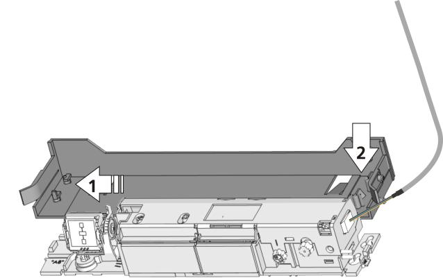
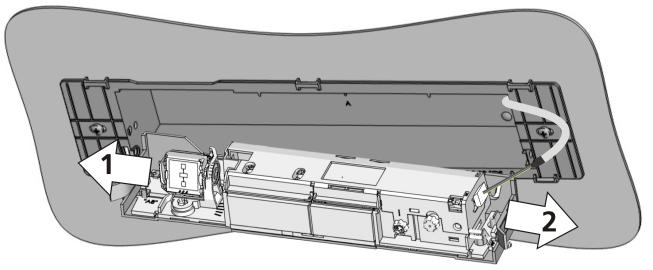
5 MOUNT DISMOUNT D00728EN - v3 2 COMMISSIONING The recommended commissioning sequence is as follows: installation, connection, start-up and settings. 2.1 MOUNTING DDS-A The DDS-A model is always installed in escape routes, and always inside the premises. DDS-A STANDARD MOUNTING 1. Remove the protective cover 2. Connect the cable 3. Position the drilling template 4. Drill the holes and remove the template 5. Pass the cable through and install the sensor Max 5cm SURFACE MOUNTING (OPTIONAL) 192 mm Slide 2 Clip Unclip 1.2 Press 5


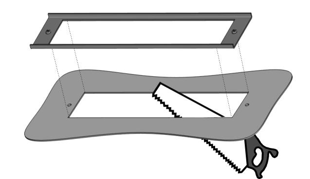
6 2.1.3 CEILING MOUNTING 1 Cut 2 Screw together 3 Clip 4 Unclip 5 Clip 6 Unclip 7 Clip 8 Clip 6
 BROWN (-) YELLOW WHITE PINK POWER SUPPLY OPENING INPUT SAFETY OUTPUT 2.2.1 CONNEC- ** GREY VIOLET YELLOW /")
 *** Bravo operators: Plug at 12")

7 DDS-B DDS-A DETECTOR D00728EN - v MOUNTING WITH RAIN PROTECTION (OPTIONAL) 2.2 WIRING 12-30V * DC GREEN (+) BROWN (-) YELLOW WHITE PINK POWER SUPPLY OPENING INPUT SAFETY OUTPUT CONNEC- ** GREY VIOLET YELLOW / BLACK + SAFETY INPUT PULL-UP*** OPENING INPUT FOR EMERGENCY EXITS (ONLY AVAILABLE FOR THE DDS-A VERSION) * Output status with the sensor in operation ** Powers supply for emergency exits (only available for the DDS-A version) *** Bravo operators: Plug at 12V a Connecting the DDS-A sensor in emergency exit doors Sensor Green Brown White Yellow Pink Grey Note: Configure the following parameters: RAD:OUTPUT = frequency PULSE INPUT = positive b Connecting the DDS-B sensor in general purpose doors Sensor Green Brown White Yellow Pink Grey Note: Configure the following parameters: RAD:OUTPUT = NO PULSE INPUT = positive 7

8 SENSOR DDS-B DDS-B D00728EN - v CONNECTION TO BRAVO OPERATOR (Only compatible with DDS-B) Note: Use the specific Bravo cable (included) Configure the following parameters: RAD:OUTPUT = NO PULSE INPUT = positive Sensor Green Brown White Yellow Pink Grey Violet CONNECTION TO ACTIVA OPERATOR (Only compatible with DDS-B) Note: Configure the following parameters: RAD:OUTPUT = NO INPUT PULSE = positive Sensor Green Brown White Yellow Pink Grey 2.3 RADAR OUTPUT CONFIGURATION (Only compatible with DDS-A) Choose the desired output type: 1. RELAY output NO: Normally OPEN NC: Normally CLOSED 2.- FREQUENCY output 3. CURRENT Output YELLOW / BLACK + WHITE / BLACK - 8


9 WIDTH ANGLE WIDTH ANGLE D00728EN - v3 2.4 FIELD SETTING SETTING THE OPENING FIELD - RADAR Choose the desired output type: Angle: -15º to +15º / field dimensions: 9 / immunity: 2 Angle: +15º to +45º / field dimensions: 9 / immunity: 2 Area: 4 x 2m / field dimensions: 9 / immunity: 2 Area: 2 x 2.5m / field dimensions: 9 / immunity: 2 The size of the detection fields varies depending on the mounting height of the sensor. For emergency exits, the entire door width should be covered SETTING THE SAFETY FIELD - INFRARED CLOSER FARTHER 9 cm x2 1 Activate visible spots 2 If necessary, adjust the angle of the infrared curtains *Visibility depends on external conditions. If the spots are not visible, the Spotfinder helps to locate the position of the curtains. **The distance between the inner curtain of the inside door sensor and the inner curtain of the outside door sensor should always be less than 20cm. The distance up to the door leaf depends therefore on the thickness of the door leaf. Possible additional settings through the LCD. Part of the emitted field can be covered in order to reduce the detection field. The position of the arrow determines the field width. Always check the field width with a piece of paper and not with the Spotfinder, that detects the entire emitted field. 9
10 4 D00728EN - v3 The size of the detection fields varies depending on the mounting height and the settings of the sensor. The sensor should cover the whole width of the door leaf/leaves. To verify, use the reference body as per EN OTHER SETTINGS Set the sensor by LCD or choose one of the presettings: 1.- STANDARD: standard in- and outdoor installations Presettings Standard 2. CRITICAL ENVIRONMENT: critical installations due to surroundings or weather (immunity 'High', 1 active curtain). Presettings Critical env. 3. SHOPPING STREET: Installations in narrow streets with pedestrian traffic (immunity: 'High', redirection: 'Safety and opening') Presettings Shopping str. 2.6 SETUP QUICK SETUP = OK 2s 1 Vacate the detection field 2 Press for 2s 3 When the LED switches off, the sensor is ready for use ASSISTED SETUP 4s 1 Vacate the detection field 2 Press for 4s 3 The door performs an opening manoeuvre. = OK 4 The door performs an closing manoeuvre. 5 When the LED switches off, the sensor is ready for use. 10


11 2.7 USING THE LCD SCREEN INSTRUCTIONS DURING NORMAL OPERATION Opening impulse Safety To adjust the contrast, simultaneously press and turn the grey button Negative display = Active output FACTORY VALUE vs. SAVED VALUE Displayed value = Factory value Displayed value = Saved Value NAVIGATING THE MENUS 30s 1 Push to enter 2 Enter password if necessary the LCD-menu Not during the first minute after power-on of the sensor 3 Select your language before entering the first LCD-menu. During the first 30 seconds after power-on of the sensor or later in the diagnostics menu. 4 Scroll menu items 5 Select Back to return to 6 Select Moret o go to next level: previous menu or display. - basic settings - advanced settings - diagnostics CHANGING VALUES 1 Scroll menu up-down 2 Push to select parameter 3 Scroll values up-down. 4 Push to save new More values are value. displayed. 11
12 3 USER MENU NAViGATION MAP: BASIC MENU Back More PRESETTINGS Standard: factory values Critical Env.: increased immunities + 1 curtain Shopping Str.: increased immunities + redirection = motion and presence RAD FIELDSIZE: Small < 1 < 2 < 3 < 4 < 5 < 6 < Factory < 8 < Large 9 RAD OUTPUT: NO > NC > freq > current IR: IMMUNITY. < 2,8 m > 2,8 m (1)Low<(2)Normal<(3)High<(4)+High*<(5)++High*< (6)Normal< (7)High For conformity with EN / DIN 18650, use values 6 y 7 at a mounting height 2,8m. BS7036: for a mounting height 2,2m use values 6 y 7. * Exclude the door from complying with EN / DIN / BS 7036 IR: FREQUENCY. A < B. Detectors installed close together should have different frequencies. More Back ADVANCED MENU Back More RAD: IMMUNITY 1 < 2 < 3 < 4 < 5 < 6 < 7 < 8 < 9 RAD: DIRECTION OFF < Bi < Mono < Uni PMR< INV < Bi auto < MONO auto < PMR auto RAD: HOLDTIME. 0,5s < 1s < 2s < 3s < 4s < 5s < 6s < 7s < 8s < 9s RAD OUTPUT: NO > NC AIR: WIDTH: Excludes the door equipment from complying with EN 16005/ DIN / BS7036. PMR: para personas con movilidad reducida / INV: detección invertida / AUTO: adaptación del tamaño del campo en pequeñas tiendas. IMPORTANTE! El modo auto de la dirección de detección no está permitido si el sensor se utiliza en salidas de emergencia It is always necessary to adjust the position of the arrows with a screwdriver. Service mode = Detections deactivated 15 min for maintenance tasks. RA: NUMBER: Service mode < 1 < 2 This value excludes compliance of the door systems with EN and with DIN IR: PRESENCE TIME < 15s < 30s < 1min < 2 min < 5 min < 10 min < 20 min < 60 min < Infinite IR: OUTPUT. Pulse PULSE INPUT. Positive < Negative REDIRECTION. Motion < Motion or presence < Motion and presence FACTORY RESET <Full reset < Partial Reset Partial: outputs are not reset DOOR BELL. Off < 0.05s < 0.10 s < 0.25 s < 0.50 s < 0.75 s < 1 s < 1.5 s < 2 s < 5 s More Back DIN min EN seg DIAGNOSTICS ZIP: All values in compressed format ID#: Unique identification number 12
13 4 TROUBLESHOOTING LED STATUS Error Solution ORANGE Flashes once Flashes twice Flashes 4 times Flashes 5 times The sensor signals an internal fault Erroneous activation of the radar without apparent outside effect The sensor is not receiving sufficient infrared energy. The sensor is receiving too much infrared energy. The sensor is disturbed by external elements. 1. Replace sensor. 1. Check the power supply in the diagnostics menu. 2. Check the wiring. 1. Check the angle of the infrared curtains. 2. Increase the AIR immunity filter: values >2.8m. 3. Deactivate 1 curtain. 1. Slightly increase the angle of the IR-curtains. 2. Decrease the IR-immunity filter (values 1-3 <2.8 m). 1. Eliminate the cause of disturbance (lamps, rain cover, door controller housing properly grounded) Flashes 6 times The radar output is defective. 1. Replace the sensor. Flashes 7 times The internal test of the radar is disturbed. 1. Change radar field angle or antenna. 2. Launch a quick setup. Flashes 8 times The AIR emitter is defective. 1. Replace the sensor. Flashes 9 times The internal reference of the radar is wrong. 1. Replace the sensor. On Problem with the sensor memory. 1. Switch the power supply OFF and ON again. 2. If the LED comes on again, replace the sensor. 1. Move the IR-curtains away from the door. RED Flashes rapidly after assisted setup The sensor sees the door During assisted SETUP The sensor vibrates 2. Install the sensor as close to the door as possible. 3. Launch a new assisted setup. Vacate the detection field! 1. Check that the sensor is correctly installed. 2. Check the position of the cable and the cover. Turns on sporadically The sensor sees the door 1. Perform another assisted SETUP and change the angle of the infrared curtains. The sensor is disrupted by external conditions 1. Increase the AIR immunity filter: value Select presetting 2 or 3. The sensor is disrupted by rain and/or tree leaves. 1. Select presetting 2 or Increase the radar immunity filter. Ghosting (continual opening and closing of the doors) 1. Change radar field angle. GREEN Turns on sporadically The sensor vibrates 1. Check that the sensor is correctly affixed. 2. Check the position of the cable and the cover. The sensor sees the door or other moving objects. 1. Remove the objects causing the disruption. 2. Change the size of the radar lobe or change the angle of the radar antenna. -- LED and LCD are off Check wiring. -- The door reaction does not correspond to the LED signal? Check output configuration setting. 2. Check wiring. -- The LCD or remote control does not react. The sensor is protected by a password. Enter the right password. If you forgot the code, cut and restore the power supply to access the sensor without entering a password during 1 minute. 13
 in the IR area. The operator cover is perfectly fitted.")
14 5 INSTALLATION CHECKLIST Check that the sensor has been firmly installed to avoid external vibrations. Do not cover the sensor. There are no moving objects or light sources in the detection field. There are no reflective objects (mirrors, stainless steel objects ) in the IR area. The operator cover is perfectly fitted. The complete installation set: door + sensors + other accessories, are all working correctly. 6 MAINTENANCE 6.1 MAINTENANCE TO BE CARRIED OUT BY THE USER Maintenance of sensors may only be carried out by technically authorised staff. The maintenance tasks reserved for the user are, exclusively, maintaining cleanliness and order around the area of the door. It is recommended to clean the optical parts whenever necessary and, in any case, at least once a year, with a slightly-damp cloth. DO NOT use aggressive cleaning products. Dispose of the sensor appropriately at the end of its useful life. 6.2 MAINTENANCE RESTRICTED TO THE MANUFACTURER Installation, maintenance, adjustment and repairing tasks on the sensors are exclusively restricted to technical staff authorised by. 14

15 7 EC DECLARATION OF CONFORMITY DECLARATION CE OF CONFORMITY Manufacturer: MANUSA Address: Product: Model: Av. Vía Augusta, 85-87, 6 th Floor Sant Cugat del Vallès Barcelona, Spain Tel Fax Hybrid electro-sensitive device for the detection of the presence and motion of individuals, suitable for installation in automatic pedestrian doors located in emergency exits. SENSOR HÍBRIDO DDS-A / DDS-B Ref: A05037 / A05038 Notified body: TÜV NORD CERT GmbH, Langemarckstrasse 20, D Essen, NB 0044, EC-type-examination certificate No We herein declare, under our sole responsibility, that the product listed and referenced complies with the following European Directives: 2006/42/CE 305/2011/CE 2004/108/CE 2006/95/CE 2011/65/CE Machinery Directive Construction Products Regulation Electromagnetic Compatibility Directive Low-voltage Equipment Directive RoHS2 Directive It has also applied the following harmonised standards and technical specifications: EN AS 5007 DIN BS 7036 UNE-EN UNE-EN ISO Authorised representative: Performance level: Presence sensor: PL d Cat 2 Motion sensor: PL d Cat 3 MANUSA DOOR SYSTEMS Av. Vía Augusta, 85-87, 6 th Floor, Sant Cugat del Vallès, Barcelona, Spain Tel: Fax: The CE marking is included in the product to indicate conformity with the essential requirements of the applicable directives. This declaration of conformity means that the machine installation and commissioning has been made in accordance with the assembly, operation and maintenance instructions from the manufacturer. Josep Mª Guilera General Manager Francesca Martínez Product Standardisation Sant Cugat del Vallès, September
16 V1 / D00728EN - v3 NOTE: The characteristics detailed in this document are for information only and do not represent any contractual obligation. The manufacturer reserves the right to make modifications without prior warning Last revision: july 2015 HEAD OFFICE Av. Vía Augusta, 85-87, 6 th Floor Sant Cugat del Vallés Barcelona - Spain Tel Fax
DDS-SSENSOR - INSTALLATION MANUAL. Installation Manual DDS-S SENSOR
 Installation Manual DDS-S SENSOR 1 TRANSLATED DOCUMENT This manual has been compiled according to standard UNE-EN-ISO 12100. INSTALLATION MANUAL DDS-S SENSOR Read thoroughly all of these instructions before
1. LCD 2. radar antenna (narrow field) 3. radar antenna (wide field) 4. AIR-curtain width adjustment 5. AIR-lenses
 3. radar antenna (wide field) 4. AIR-curtain width adjustment 5. AIR-lenses") IXIO-DT INDUSTRIAL Activation & safety sensor for industrial doors (US Version) ENGLISH DESCRIPTION 3 4 5 6 7 8 9 ACCESSORIES. LCD. radar antenna (narrow field) 3. radar antenna (wide field) 4. AIR-curtain
IXIO-DT INDUSTRIAL Activation & safety sensor for industrial doors (US Version) ENGLISH DESCRIPTION 3 4 5 6 7 8 9 ACCESSORIES. LCD. radar antenna (narrow field) 3. radar antenna (wide field) 4. AIR-curtain
Download the BEA DECODER app for a quick overview of settings
 Download the BEA DECODER app for a quick overview of settings IXIO-DT1 Activation & safety sensor for automatic sliding doors ENGLISH DESCRIPTION 1 2 3 4 5 6 7 8 9 1. LCD 2. radar antenna (narrow field)
Download the BEA DECODER app for a quick overview of settings
 Download the BEA DECODER app for a quick overview of settings IXIO-DT1 V Activation & safety sensor with camera for automatic sliding doors ENGLISH DESCRIPTION 1 2 3 4 5 6 7 8 9 10 1. LCD 2. radar antenna
ACTIV8 ONE OFF. 1 Tips USER S GUIDE COMBINED RADAR OPENING AND ACTIVE INFRARED SAFETY SENSOR. 1 Description. 2 Symbols.
 ACTIV8 ONE OFF USER S GUIDE COMBINED RADAR OPENING AND ACTIVE INFRARED SAFETY SENSOR 1 Description Cover 2 nd Radar Antenna Radar motion sensor Push-Buttons IR-Presence sensor Radar Antenna clip IR-Prism
LZR -I100/ -I110. LASER SCANNERS for industrial doors. User s Guide for product version 0600 and more
 EN LZR -I00/ -I0 LASER SCANNERS for industrial doors I00: max. detection range of 9.9 m x 9.9 m I0: max. detection range of 5.0 m x 5.0 m User s Guide for product version 0600 and more SAFETY The device
LZR -I30. max. detection range of 30 ft x 30 ft LASER SCANNERS FOR INDUSTRIAL DOORS LZR-I Page 1 of 12
 EN LZR -I30 LASER SCANNERS FOR INDUSTRIAL DOORS max. detection range of 30 ft x 30 ft 75.5667.07 LZR-I30 0509 Page of SAFETY The device contains IR and visible laser diodes. IR laser: wavelength 905nm;
XGUARD-10/-5. LASER SCANNERS for industrial doors. User s Guide for product version 0600 and more
 EN XGUARD-0/-5 LASER SCANNERS for industrial doors XGUARD-0: max. detection range of 9.9 m x 9.9 m XGUARD-5: max. detection range of 5.0 m x 5.0 m User s Guide for product version 0600 and more SAFETY
LZR -WIDESCAN OPENING, PRESENCE & SAFETY SENSOR FOR INDUSTRIAL DOORS
 LZR -WIDESCAN EN OPENING, PRESENCE & SAFETY SENSOR FOR INDUSTRIAL DOORS User s Guide for product version 0300 and higher See product label for serial number INSTALLATION & MAINTENANCE & TIPS Avoid extreme
active infrared 875 nm < 250 mw/m² motion & presence 157 in x 157 in (emitting spots**) 2 in/s to activate detection 250 ms 15-45
 2 in/s to activate detection 250 ms 15-45") Please keep for further use Designed for color printing Other use of the device is outside the permitted purpose and can not be guaranteed by the manufacturer. The manufacturer cannot be held responsible
Please keep for further use Designed for color printing Other use of the device is outside the permitted purpose and can not be guaranteed by the manufacturer. The manufacturer cannot be held responsible
LZR -H110. LASER SCANNER FOR BARRIERS & GATES with max. detection range of 5.0 m x 6.5 m (16.5 ft x21 ft) User s Guide
 User s Guide") EN LZR -H110 LASER SCANNER FOR BARRIERS & GATES with max. detection range of 5.0 m x 6.5 m (16.5 ft x21 ft) User s Guide 75.5897.02 LZR-H110 20170821 Page 1 of 12 SAFETY The device contains IR and visible
EN LZR -H110 LASER SCANNER FOR BARRIERS & GATES with max. detection range of 5.0 m x 6.5 m (16.5 ft x21 ft) User s Guide 75.5897.02 LZR-H110 20170821 Page 1 of 12 SAFETY The device contains IR and visible
LZR -WIDESCAN. Motion, Presence, and Safety Sensor for Industrial Doors (US version) DESCRIPTION ENGLISH
 DESCRIPTION ENGLISH") LZR -WIDESCAN Motion, Presence, and Safety Sensor for Industrial Doors (US version) ENGLISH DESCRIPTION 6 7 8 9 0 2 3 2 3 4 5 4. main connector 2. protection film 3. laser window 4. USB cap 5. LED display
LZR -WIDESCAN Motion, Presence, and Safety Sensor for Industrial Doors (US version) ENGLISH DESCRIPTION 6 7 8 9 0 2 3 2 3 4 5 4. main connector 2. protection film 3. laser window 4. USB cap 5. LED display
LZR -FLATSCAN SW SAFETY SENSOR FOR FULL- AND LOW-ENERGY AUTOMATIC SWING DOORS. Visit website for available languages of this document.
 EN LZR -FLATSCAN SW SAFETY SENSOR FOR FULL- AND LOW-ENERGY AUTOMATIC SWING DOORS Visit website for available languages of this document. 75.5947.03 LZR-FLATSCAN SW 20190206 Page 1 of 16 DESCRIPTION 1 2
LZR -FLATSCAN SW SAFETY SENSOR FOR FULL- AND LOW-ENERGY AUTOMATIC SWING DOORS
 EN LZR -FLATSCAN SW SAFETY SENSOR FOR FULL- AND LOW-ENERGY AUTOMATIC SWING DOORS 75.5947.01 LZR-FLATSCAN SW 20180627 Page 1 of 16 DESCRIPTION 1 2 3 4 5 6 7 8 11 12 13 14 15 16 9 10 17 18 1. cover 2. push
DHR3. Accessories. NOTE: Set up for this sensor should be performed by an AAADM-certified installer. INSTALLATION INSTRUCTIONS
 NOTE: Set up for this sensor should be performed by an AAADM-certified installer. Section 1 General Description The DHR3 is a combination microwave/infrared sensor providing both motion detection and presence
Instruction manual. Digital Radar Motion Detector with Infrared Remote Control MWD BF. FEIG ELECTRONIC GmbH Lange Straße Weilburg/Lahn
 Instruction manual Digital Radar Motion Detector with Infrared Remote Control MWD BF FEIG ELECTRIC GmbH Lange Straße 4 35781 Weilburg/Lahn 22.08.02 MWD BF Instruction manual General Copyright 2002 by FEIG
Dimensions. Model Number. Electrical connection. Features. Product information. Indicators/operating means RMS-G-RC. Radar sensor
 Dimensions ø.7 9.5 6.5 8.5 ø.7 65 57 Window for LED display Model Number Radar sensor Features Industrial gate opener with the ability to differentiate between people and vehicles Extra-wide detection
Dimensions. Model Number 123. Electrical connection. Features. Indicators/operating means. Product information RMS-G-RC-NA.
 Dimensions ø.7 9.5 6.5 8.5 ø.7 65 57 Window for LED display Model Number Radar sensor Features Industrial gate opener with the ability to differentiate between people and vehicles Extra-wide detection
DH400. Accessories. NOTE: Set up for this sensor should be performed by an AAADM-certified installer.
 NOTE: Set up for this sensor should be performed by an AAADM-certified installer. Section 1 General Description The is a high mount microprocessor controlled active infrared presence detector for all types
/ / 2018
 Original operating instructions Photoelectric safety sensors (safety light curtain / safety light grid) with IP69K protective tube Protected area width (range) 0...10 m OY4xxS UK 704859 / 05 02 / 2018
POL-200-TS User Manual
 User Manual POL-200-TS ANALOGUE LOOP VERIFICATION TOOL 1/16 Security Information Several damage! Please, before to connect any external cable, ensure that loop cable has been disconnected from panel loop
Installation manual VISIO HERMÉTICO
 Installation manual VISIO HERMÉTICO 1 2 TRANSLATED DOCUMENT Carefully read these instructions in their entirety before starting to use the unit. INSTALLATION MANUAL VISIO HERMÉTICO OPERATOR This manual
Detector switch - Dual Tech SCS
 0 672 26 0 784 86 5 740 48 5 740 98 Page 1. Use...1 2. Technical characteristics....1 3. Dimensions....1 4. Connection...1 5. Installation...2 6. Operation...2 7. Settings...2 8. Configuration....3 9.
Dimensions. Electrical connection. Model Number. Features. Indicators/operating means. Product information RAVE-D. Radar sensor
 Dimensions 139.6 103 99.6 46 130.7 Electrical connection Model Number Radar sensor Features Degree of protection IP67 Differentiated detection of people and vehicles, each with one output relay Cross-traffic
D-TECT 3 IP. GJD260 IP Motion Detector
 D-TECT 3 IP GJD260 IP Motion Detector PACKAGE CONTENTS 1 x D-TECT 3 IP 1 x Drilling template for fixing holes 3 x 31.75mm wall plugs 3 x 31.75mm screws 2 x Spare sliding curtains 2 x Tamper feet 1 x Tamper
Controlled access gates especially designed to allow people quick, safe and controlled access to installations of all types.
 TRANSLATED DOCUMENT Data Sheet EXPRESS GATE 1 - DESCRIPTION Express Gate PAR (Reversible Automatic Access Control Gate) Express Gate PMR (PAR for people with limited mobility) i Controlled access gates
Instructions for the fan motor control system with integrated wiring terminals SILVER C
 Instructions for the fan motor control system with integrated wiring terminals SILVER C 1. General The motor control system is used for controlling the type EC, 0.41-10 kw fan motors in the SILVER C units.
C-Bus PIR Occupancy Sensor. Installation Instructions 5751L
 C-Bus PIR Occupancy Sensor Installation Instructions 5751L Contents 1.0 Description 3 2.0 Important Notes 3 3.0 Installation 3 4.0 C-Bus Network Connection 6 5.0 Programming and Setup 7 6.0 Troubleshooting
SWARCO TRAFFIC SYSTEMS GMBH. TDD1-MW Traffic Detector User Manual TDD1-MW_BE_00
 TDD1-MW Traffic Detector User Manual TDD1-MW_BE_00 CONTENTS 1 Introduction... 3 1.1 About this manual... 3 1.2 Usage according to regulations... 3 1.3 Label... 4 1.4 Symbols... 4 1.5 Safety instructions...
Dimensions. Electrical connection. Model Number. Features. Indicators/operating means. Product information RAVE-D-NA. Radar sensor
 Dimensions 139.6 103 99.6 46 130.7 Electrical connection Model Number Radar sensor Features Degree of protection IP67 Differentiated detection of people and vehicles, each with one output relay Cross-traffic
BODYGUARD-T USER S GUIDE
 BODYGUARD-T USER S GUIDE NOTE: For BODYGUARD-TC functionality, set Immunity to 3-HIGH. PRESENCE SENSOR w/monitoring DESCRIPTION The BEA Bodyguard-T (10BODYGUARDT) are self-monitored, ready overhead-mounted,
VISIO HERMÉTICO OPERATOR
 TRANSLATED DOCUMENT Data Sheet VISIO HERMÉTICO OPERATOR 1 - DESCRIPTION i Op. Side Right (1 leaf) Op. Side Left (1 leaf) Op. Side (2 Leaves) Operator for hermetic automatic sliding door, in side opening
BSR Addressable Fire Detection control panel. Installation operation manual
 BSR-1116 Addressable Fire Detection control panel Installation operation manual ATTENTION!!! READ THE MANUAL BEFORE THE INSTALLATION AND PAY ATTENTION TO PARAGRAPH 2.6.3 AND 2.6.4. Page 2 from 36 Contents
Original operating instructions Photoelectric safety sensors (safety light curtain / safety light grid) Protected area width (range) 0...
 Protected area width (range) 0...") Original operating instructions Photoelectric safety sensors (safety light curtain / safety light grid) Protected area width (range) 0...12 m OY UK 704555 / 05 02 / 2018 Contents 1 Preliminary note...4
Original operating instructions Photoelectric safety sensors (safety light curtain / safety light grid) Protected area width (range) 0...12 m OY UK 704555 / 05 02 / 2018 Contents 1 Preliminary note...4
Laser Collimated Beam Sensor
 SERIES Laser Collimated Beam Sensor Class 1 Laser Beam Sensor Safe for Your Eyes Marked Conforming to EMC Directive (Excluding LA-C1) Safe Laser Beam This laser collimated beam sensor conforms to the Class
80 CHANNELS WIRELESS RECEIVER WITH LCD DISPLAY M1.1.1-Hx.x-F1.1-ENG [AN] [SPV] MADE IN ITALY INSTALLATION AND USE MANUAL
![80 CHANNELS WIRELESS RECEIVER WITH LCD DISPLAY M1.1.1-Hx.x-F1.1-ENG [AN] [SPV] MADE IN ITALY INSTALLATION AND USE MANUAL](/thumbs/72/67367199.jpg "80 CHANNELS WIRELESS RECEIVER WITH LCD DISPLAY M1.1.1-Hx.x-F1.1-ENG [AN] [SPV] MADE IN ITALY INSTALLATION AND USE MANUAL") RX808-LCD 80 CHANNELS WIRELESS RECEIVER WITH LCD DISPLAY 14.12-M1.1.1-Hx.x-F1.1-ENG [AN] [SPV] MADE IN ITALY INSTALLATION AND USE MANUAL WARNINGS Installation: This device must be installed only by qualified
RX808-LCD 80 CHANNELS WIRELESS RECEIVER WITH LCD DISPLAY 14.12-M1.1.1-Hx.x-F1.1-ENG [AN] [SPV] MADE IN ITALY INSTALLATION AND USE MANUAL WARNINGS Installation: This device must be installed only by qualified
SCHMIDT LED Measured Value Display MD Instructions for Use
 SCHMIDT LED Measured Value Display MD 10.010 Instructions for Use Table of Contents 1 Important Information... 3 2 Application range... 4 3 Mounting instructions... 4 4 Electrical connection... 6 5 Signalizations...
HR-Robus. Included INSTALLATION INSTRUCTIONS. Industrial Door Microwave Motion Sensor
 Section 1 General Description The is a microwave motion sensor for activating automatic industrial doors. Features include a speed selectable switch that makes the unit capable of detecting pedestrians
2 Ensure that all personnel in the area are wearing the appropriate protective eyewear.
 SYNRAD, Inc. 4600 Campus Place Mukilteo, WA 98275 tel 1.425.349.3500 fax 1.425.349.3667 e-mail synrad@synrad.com web www.synrad.com Power Wizard PW-250 Operating Instructions Important Power Wizard power
DRYTEK 1 - User Manual ELECTRICAL PANEL FOR 1 MOTOR WITH POWER FACTOR CONTROL
 DRYTEK 1 - User Manual ELECTRICAL PANEL FOR 1 MOTOR WITH POWER FACTOR CONTROL CONTENTS 1. INTRODUCTION... 5 2. WARNINGS... 6 3. GENERAL DESCRIPTION... 7 4. INSTALLATION... 8 5. CONTROL PANEL... 9 5.1
INDEX 1- Introduction The Control Pane...7l 4.1- The Control Panel 1 and 2 Loops The Control Panel 4 and 8 Loops...
 GUIDE MANUAL INDEX 1- Introduction...5...5...6 4- The Control Pane...7l 4.1- The Control Panel 1 and 2 Loops...7 4.2- The Control Panel 4 and 8 Loops...9 5- Installation Guide...10 5.1- Pre-Installation
Ceiling Microwave presence detector - DALI / DSI 12-24V AC/DC. Microwave Sensor. IR Receiver. Light Level Sensor. Status LEDs.
 MWS6-DD-LV Product Guide Ceiling Microwave presence detector - DALI / DSI 12-24V AC/DC Overview The MWS6-DD-LV microwave presence detector provides automatic control of lighting loads with optional manual
Motorised Infrared Optical Beam Smoke Detector. User Guide
 Motorised Infrared Optical Beam Smoke Detector User Guide EN 1. General Information 50cm 50cm 8-100m Ensure clear line of sight from Detector to Reflector Mount on solid surfaces (structural wall or girder)
Original operating instructions Safety switch with guard locking AC901S AC902S
 Original operating instructions Safety switch with guard locking AC901S AC902S 7390914/03 01/2017 Contents 1 Preliminary note...4 1.1 Explanation of symbols...4 2 Safety instructions...4 3 Items supplied...5
Radio fire warning panel SRC 3000
 Radio fire warning panel SRC 3000 6 zone radio fire warning panel Operating instructions Version 1.2 Art. 32487 detectomat GmbH Headquarter: Phone: +49 (0) 4102-2114-60 An der Strusbek 5 Fax: +49 (0) 4102-2114-670
Safety. Detection. Control. SAFETY INTERFACES. Safety Interfaces and Relays. Product catalogue. Issue 1
 Safety. Detection. Control. Issue 1 SAFETY INTERFACES Safety Interfaces and Relays Product catalogue OVERVIEW SAFETY INTERFACES AND RELAYS MG d1 PL d control unit for ReeR Magnus magnetic switches See
Motorised Infrared Optical Beam Smoke Detector. User Guide
 Motorised Infrared Optical Beam Smoke Detector User Guide EN 1. General Information 50cm 50cm 8-100m Ensure clear line of sight from Detector to Reflector Mount on solid surfaces (structural wall or girder)
4-Row Active Infrared Presence Detector for Automatic Door Control. Cover
 Section 1 General Description The is a -row microprocessor controlled active infrared presence detector for all types of automatic doors. Wide and narrow pattern width of the sensor is adjustable by twin
Instructions for Use
 T-1165 e 19.4.12 Translation of the original instructions for use Instructions for Use For Automatic Sliding Doors with Drive Win Drive 2201 Sliding Door Drive Contents 1 General Information 3 2 Safety
MWS3 Ceiling Mount Microwave Occupancy Detector
 MWS3_0916/ISSUE1 MWS3 Ceiling Mount Microwave Occupancy Detector Description: the MW3SA offers a unique presence/absence detection capability by using an adjustable head. This incorporates an innovative
Siemens aspirating smoke detector (ASD) for the addressed FDnet/C-NET detector line or for standalone operation
 for the addressed FDnet/C-NET detector line or for standalone operation") Sinteso Cerberus PRO FDA241, FDA221 ASD Aspirating smoke detector Siemens aspirating smoke detector (ASD) for the addressed FDnet/C-NET detector line or for standalone operation Patented technology Early
Sinteso Cerberus PRO FDA241, FDA221 ASD Aspirating smoke detector Siemens aspirating smoke detector (ASD) for the addressed FDnet/C-NET detector line or for standalone operation Patented technology Early
RVA /109. Heating Circuit ZONE Controller. Instructions for the INSTALLER
 Heating Circuit ZONE Controller RVA 46.531/109 Zonal temperature controller for control of a lowtemperature heating system, for use with condensing gas boilers Instructions for the INSTALLER INDEX Page
HANDBUCH / MANUAL / MANUEL / MANUALE TopScan-S
 FACTORY AUTOMATION HANDBUCH / MANUAL / MANUEL / MANUALE TopScan-S Certification Type Tested Inhalt / Content / Sommaire / Indice Deutsch......................................................... 3 English.........................................................
A-MIP 210 Installation and user guide
 20 A-MIP 20 Installation and user guide General Information Important Read this manual before installation and use of the Aivia. Read this section carefully and follow the instructions. The warranty does
Class 1 laser beam sensor safe for your eyes
 113 Sensor SERIES Related Information General terms and conditions... F-7 About laser beam... P.199~ Sensor selection guide... P.1~ General precautions... P.11 PHOTO PHOTO PARTICUR MEASURE ITY panasonic.net/id/pidsx/global
Ceiling Microwave presence/absence detector 12-24V AC/DC
 MWS3A-PRM-LV Product Guide Ceiling Microwave presence/absence detector 12-24V AC/DC Overview The MWS3A-PRM-LV Microwave presence detector provides automatic control of low voltage loads including lighting
Instructions for the fan motor control system, SILVER C
 Instructions for the fan motor control system, SILVER C 1. General The motor control system is used for controlling the type EC, 0.41-10 kw fan motors in the SILVER C units. The motor control system is
1.7 A-ISOMETER IRDH575. RoHS. Dipl.-Ing. W. Bender GmbH & Co. KG Londorfer Str Grünberg Tel.: Fax:
 Dipl.-Ing. W. Bender GmbH & Co. KG Londorfer Str. 65 505 Grünberg Tel.: 060 807-0 Fax: 060 807-59 A-ISOMETER IRDH575 Insulation monitoring device for unearthed AC, DC and AC/DC systems (IT systems) with
DOL 31 Speed Controller Technical User Guide
 Technical User Guide For other language variants of this document we refer to your local dealer or http://docs.skov.com/1158. Available from April 2016. 612061 2016.09.20 Technical User Guide Program
SCS motion sensors Surface/wall mounting - PIR
 IP55 Page 1. Use.....................................1 2. Technical characteristics................1 3. Dimensions............................1 4. Connection.............................1 5. Removal................................2
MPAD-C 12-24V. Ceiling microwave presence/absence detector 12-24V AC/DC. Product Guide. Overview. Features
 Product Guide MPAD-C 12-24V Ceiling microwave presence/absence detector 12-24V AC/DC Overview The MPAD-C 12-24V Microwave presence detector provides automatic control of low voltage loads including lighting
Operating instructions Safety-monitoring module SRB 302X3. 1. About this document. Content
 8 Appendix 8.1 Wiring examples...4 8.2 Start configuration...4 8.3 Sensor configuration...4 8.4 Actuator configuration...5 Operating instructions.............pages 1 to 6 Original 9 EU Declaration of conformity
S304 and S305 Dust Emission Monitors. User Manual. Distributor
 S304 and S305 Dust Emission Monitors User Manual Distributor Version 6.4 30/5/2012 Table of Contents 1. INTRODUCTION... 3 1.1 Safety... 3 1.2 Product overview... 4 1.3 Principle of operation... 4 2. INSTALLATION...
Instructions for Use
 T-1672 e 4.4.14 Translation of the original instructions for use Instructions for Use For Automatic Sliding Doors with Drive TORMAX 2101 Sliding Door Drive Safety instructions in chapter 2 must be observed!
INSTRUCTION MANUAL T119 1MN0110 REV. 0. operates with ISO9001 certified quality system
 INSTRUCTION MANUAL 1MN0110 REV. 0 operates with ISO9001 certified quality system TECSYSTEM S.r.l. 20094 Corsico (MI) Tel.: +39-024581861 Fax: +39-0248600783 http://www.tecsystem.it R. 1.1 25/08/16 ENGLISH
EVC-P CONVENTIONAL PHOTOELECTRIC SMOKE DETECTOR. instruction manual. evolution EVC-P Conventional Photoelectric Smoke Detector
 EVC-P CONVENTIONAL PHOTOELECTRIC SMOKE DETECTOR instruction manual Ref No: NISM/EVC-P/03 Date: Jan 2010 Issue: 3 Quality System Certificate No. 041 Assessed to BS EN ISO 9001:2000 NITTAN (UK) LTD. Hipley
Instructions for the heat exchanger control system SILVER C RX, RECOnomic, sizes 100/120, RECOsorptic, sizes
 Instructions for the heat exchanger control system SILVER C RX, RECOnomic, sizes 100/120, RECOsorptic, sizes 50-120 1 General The heat exchanger control system is a control system for 380 W step motors
Class 1 laser beam sensor safe for your eyes
 13 Sensor SERIES Related Information General terms and conditions... F-17 About laser beam... P.13~ Sensor selection guide... P.967~ General precautions... P.1 PHOTO PHOTO Conforming to EMC Directive Conforming
Class 1 laser beam sensor safe for your eyes
 1129 PHOTO PHOTO PARTICUR Sensor SERIES Related Information General terms and conditions... F-3 About laser beam... P.193~ guide... P.121~ General precautions... P.19 Conforming to FDA regulations (-11
ABLOY DA460 SWING DOOR OPERATOR. Installation and commissioning manual
 ABLOY DA460 SWING DOOR OPERATOR Installation and commissioning manual APPROVALS / STANDARDS 73/23/EEC (Low Voltage directive) 93/68/EEC (Low Voltage directive) 89/336/EEC (EMC directive) Statement of fire
English. Italiano. Português. Françias. Español
 DT AM Grade 3 Español Françias Português Italiano English High Ceiling Mount Detector Installation Guide English DT AM Grade 3 High Ceiling Mount Detector Installation Guide General Description The Industrial
Operating instructions Safety-monitoring module SRB 302X3. 1 About this document
 1 About this document Operating instructions... pages 1 to 6 Translation of the original operating instructions 1.1 Function This operating instructions manual provides all the information you need for
1. Product characteristics 4 2. Safety 5 3. Proper use 5 4. Operation 6
 307214 1103107701 EN Presence detector theronda S360-101 DE WH 2080565 theronda S360-101 DE GR 2080566 theronda S360-101 AP WH 2080555 theronda S360-101 AP GR 2080556 1. Product characteristics 4 2. Safety
CarSense 303 O P E R A T I N G I N S T R U C T I O N S M A G N E T O R E S I T I V E V E H I C L E D E T E C T O R
 O P E R A T I N G I N S T R U C T I O N S CarSense 303 TM M A G N E T O R E S I T I V E V E H I C L E D E T E C T O R 4564 Johnston Parkway, Cleveland, Ohio 44128 P. 800 426 9912 F. 216 518 9884 Sales
Laser Distance Sensor Type M Analog-Output
 Laser Distance Sensor Type M Analog-Output Operating Manual Version 2.3, May 2009 ELAG Elektronik AG l Stegackerstrasse 14 l CH-8409 Winterthur Contents 1. Safety 1.1 Laser safety 1.2 Electrical safety
Table of Content LT 5165-UL
 Table of Content LT 565-UL. User manual.... Legal regulations... 3. Safety instructions... 3 4. Technical information... 4 5. Technical data... 4 6. Performance Graph... 5 7. Mounting... 6 8. Mounting
Instructions for Use
 T-1321 e 6.12.13 Translation of the original instructions for use Instructions for Use For Automatic Sliding Doors with Drive imotion 2202 Sliding Door Drive imotion 2202.A Sliding Door Drive imotion 2301
AO Annunciator Module
 General Specifications GS48C43Z01-00E-N AO-543-01 Annunciator Module GENERAL Figure 1 This module has two independent annunciator circuits. The circuits handle fault signals and operator actions (acknowledge,
Sensing light curtain as per DIN 18650/EN 16005
 TÜV NORD CERT B GmbH Sensing light curtain as per DIN 8650/EN 6005 -DS-P-00/30 Dimensions 38 L 4 aumuster geprüftf Zertifiziert nach DIN 8650 In accordance with Model Number -DS-P-00/30 Active infrared
Industrial Solid State Contactor TE10S. Static switching of resistive loads and shortwave infrared heating tubes up to 20 kw
 Industrial Solid State Contactor TE10S Static switching of resistive loads and shortwave infrared heating tubes up to 20 kw Partial load failure (PLF) detection option User Manual Copyright Eurotherm Automation
ivector HEATER/COOLER 2 AND 4-PIPE MODELS.
 25278 ivector Installation Guide US 02/01/2013 09:24 Page 2 ivector HEATER/COOLER 2 AND 4-PIPE MODELS. INSTALLATION, OPERATING, MAINTENANCE & AFTER SALES MANUAL JANUARY 2013, ISSUE 1 Product Serial Number:
External Wireless Sounder
 External Wireless Sounder Model: WL RWS401 Installation and Programming Instructions Table of Contents Introduction... 3 Operational Functions... 3 Alarm / Tamper Indication... 3 Low Battery Indication...
Room thermostats with LCD for wall mounting
 s 3 181 RDG100 / RDG110 RDG140 / RDG100 RDG100/H Room thermostats with LCD for wall mounting for fan coil unit applications for universal applications for use with compressors in dx type equipment RDG1
Product Guide. Ceiling microwave presence detector DALI / DSI. Microwave Sensor. IR Receiver. Light Level Sensor. Status LEDs.
 MPAD-C-DALI-230V Product Guide Ceiling microwave presence detector DALI / DSI Overview The MPAD-C-DALI-230V microwave presence detector provides automatic control of lighting loads with optional manual
Rota-Sonde DC4000-L. Laser pointer for easy alignment. Remote control of the sensitivity
 Scanning HOT METAL DETECTOR Rota-Sonde DC4000-L Two sensitivity ranges : 400 C and 230 C Laser pointer for easy alignment Remote control of the sensitivity Self-monitoring ISO 9001 Applications Benefits
panasonic.net/id/pidsx/global Lights up when conditions are normal (and at incipient liquid leak detection) Use as a warning Sensor
 Use as a warning Sensor") 867 Safety Sensor SERIES Related Information General terms and conditions... F-3 General precautions... P.1595 guide... P.865~ Korea s S-mark... P.1602 PHOTO PHOTO Certified by NRTL Conforming to SEMI-S2
867 Safety Sensor SERIES Related Information General terms and conditions... F-3 General precautions... P.1595 guide... P.865~ Korea s S-mark... P.1602 PHOTO PHOTO Certified by NRTL Conforming to SEMI-S2
SOUND-INSULATED FAN. Iso-K OPERATION MANUAL. Iso-K_v.1(2)-EN.indd :20:59
-EN.indd :20:59") SOUND-INSULATED FAN OPERATION MANUAL _v.1(2)-en.indd 1 10.08.2015 15:20:59 CONTENT Introduction 3 General 3 Safety rules 3 Transport and storage requirements 3 Manufacturer's warranty 3 Fan design 4 Delivery
SOUND-INSULATED FAN OPERATION MANUAL _v.1(2)-en.indd 1 10.08.2015 15:20:59 CONTENT Introduction 3 General 3 Safety rules 3 Transport and storage requirements 3 Manufacturer's warranty 3 Fan design 4 Delivery
Operator systems for garage doors Highline 10, 15, 18
 GB Operating instructions Last updated: 04.2016 Operator systems for garage doors Highline 10, 15, 18 Table of Contents 1. General safety instructions...3 1.1 Intended use...3 1.2 Target group...3 1.3
Fume Hood Operating Display Panel
 Desigo TRA Fume Hood Operating Display Panel QMX3.P87 The Operating Display Panel (ODP) is the interface between the operator and the DXR Fume Hood Controller (FHC). LCD display for volume flow setpoint,
USER GUIDE. DRENA 2 - User Manual ELECTRICAL PANEL FOR 2 MOTORS - WASTE WATER -
 USER GUIDE DRENA 2 - User Manual ELECTRICAL PANEL FOR 2 MOTORS - WASTE WATER - II CONTENTS 1. SYMBOLS AND WARNINGS... 5 2. GENERAL INFORMATION... 6 3. WARNINGS... 7 4. GENERAL DESCRIPTION... 8 5. INSTALLATION...
Safety Temperature Limiter STL 50 Certified to DIN EN (replaces DIN 3440)
") Safety Temperature Limiter STL 50 Certified to DIN EN 14597 (replaces DIN 3440) Features M For use as: STB Protection - temperature limiter ASTB Exhaust gas - protection - temperature limiter STW Protection
Safety Temperature Limiter STL 50 Certified to DIN EN 14597 (replaces DIN 3440) Features M For use as: STB Protection - temperature limiter ASTB Exhaust gas - protection - temperature limiter STW Protection
MC 31 Speed Controller Technical User Guide Code no GB
 Technical User Guide Code no. 99-97-0968 GB Ausgabe: 0 /201 Technical User Guide Program Version The product described in this manual holds software. This manual corresponds to: Software version 1.3 It
Installation and operation manual DPC200 - DIFFERENTIAL PRESSURE CONTROLLER. Low pressure with PI-control-mode
 Installation and operation manual DPC200 - DIFFERENTIAL PRESSURE CONTROLLER Low pressure with PI-control-mode Manufacturer: Phone: Fax: E-Mail: Website: Issue: Doc.-no.: Arthur Grillo GmbH Am Sandbach
Ceiling PIR presence detector DALI / DSI dimming. PIR Sensor. IR Receiver. Light Level Sensor. Status LEDs. PIR Sensor.
 Product Guide EBDSM-DD Ceiling PIR presence detector DALI / DSI dimming Overview The EBDSM-DD PIR (passive infrared) presence detector provides automatic control of lighting loads with optional manual
TC515 and TC600 Installation Manual. a Winters company
 THERMOLINE TEMPERATURE CONTROLLERS TC515 and TC600 Installation Manual a Winters company Guarantee 12 months Congratulations on the purchase of this new product. Special care with the design, workmanship
CarSense 303 O P E R A T I N G I N S T R U C T I O N S M A G N E T O R E S I T I V E V E H I C L E D E T E C T O R
 O P E R A T I N G I N S T R U C T I O N S CarSense 303 TM M A G N E T O R E S I T I V E V E H I C L E D E T E C T O R 4564 Johnston Parkway, Cleveland, Ohio 44128 P. 800 426 9912 F. 216 518 9884 Sales
RS Pro Infrared Temperature Sensor
 Instruction Manual RS Pro Infrared Temperature Sensor Stock Number: 161-8103 Introduction The RS Pro Infrared Temperature Sensor is a device for measuring the temperature of the surface of a solid or liquid
DPR-145 TEMPERATURE PROTECTION RELAY. DPR-145 User Manual V-2.0 ( ) PT100 INPUTS: 4 RELAY OUTPUTS: 4 RS-485 MODBUS PORT VDC SUPPLY -1-
 PT100 INPUTS: 4 RELAY OUTPUTS: 4 RS-485 MODBUS PORT VDC SUPPLY -1-") DPR-45 User Manual V-2.0 (2..206) DPR-45 TEMPERATURE PROTECTION RELAY PT00 INPUTS: 4 RELAY OUTPUTS: 4 RS-485 MODBUS PORT 9-50VDC SUPPLY DESCRIPTION DPR-45 is a precision unit designed for the temperature
DPR-45 User Manual V-2.0 (2..206) DPR-45 TEMPERATURE PROTECTION RELAY PT00 INPUTS: 4 RELAY OUTPUTS: 4 RS-485 MODBUS PORT 9-50VDC SUPPLY DESCRIPTION DPR-45 is a precision unit designed for the temperature
DUAL TECHNOLOGY SENSOR (PIR + Microwave) Outdoor use INSTALLATION MANUAL
 Outdoor use INSTALLATION MANUAL") DUAL TECHNOLOGY SENSOR (PIR + Microwave) Outdoor use INSTALLATION MANUAL 1. DESCRIPTION Dual Technology Sensor (PIR + Microwave). AND operation in the prevention of "false alarms". IP65 (indoor and outdoor).
DUAL TECHNOLOGY SENSOR (PIR + Microwave) Outdoor use INSTALLATION MANUAL 1. DESCRIPTION Dual Technology Sensor (PIR + Microwave). AND operation in the prevention of "false alarms". IP65 (indoor and outdoor).
Dipl.-Ing. W. Bender GmbH & Co. KG Londorfer Str Grünberg Tel.: Fax:
 Dipl.-Ing. W. Bender GmbH & Co. KG Londorfer Str. 5 505 Grünberg Tel.: 00 807-0 Fax: 00 807-259 Insulation monitoring device for unearthed AC/DC systems (IT systems for the supply of operating theatre