A-MIP 210 Installation and user guide
|
|
|
- Rudolf Greene
- 5 years ago
- Views:
Transcription


1 20 A-MIP 20 Installation and user guide

2 General Information Important Read this manual before installation and use of the Aivia. Read this section carefully and follow the instructions. The warranty does not cover damage caused by failure to follow these instructions. AIVIA PROTECTION are wall mounted protection units that serve to house and shelter AEDs. The AIVIA PROTECTION does not ensure control of the AED, it is the sole responsibility of the DISTRIBUTOR to inform their own SUB-DISTRIBUTORS and USERS of their obligation to verify the presence and operating status of the AED by carrying out regular on site checkups. Depending on the options chosen, the AIVIA PROTECTION can trigger a visual and sound alarm. The alarm is intended as a warning signal in case of any malfunction, but no data log of malfunctions is recorded. In no event can the presence and operating status of AEDs in an AIVIA PROTECTION be controlled from a distance. The AIVIA should in no case be a substitute for the checks and inspections recommended by the manufacturer of the defibrillator. Installation must be carried out by a qualified operator or authorized by the Aivia s manufacturer Never install an AIVIA in direct exposure to sunlight. The unheated AIVIA must be installed in a temperate environment, in accordance with the manufacturer s s p e c i f i c a t i o n s f o r t h e d e f i b r i l l a t o r. The heated AIVIA must be installed in an environment that respects the operating temperatures of the AIVIA. You must monitor and follow up alerts related to temperature. The characteristics of the AIVIA are subject to changes without notice. The fixations must be adapted to the type of surface on which the AIVIA is fixed. The manufacturer cannot be held liable for improper installation or in the case of accident or injury during its installation. Warranty Do not disassemble the various elements that constitute the AIVIA. Do not insert any objects into any openings. Only qualified personnel may carry out repairs on the AIVIA. Failure to comply with this will void any warranty. Any operation or assembly procedures expressly prohibited or not recommended by this manual, will also void the warranty. Environmental information When returning the AIVIA, you should only use the original packaging. Do not dispose of the AIVIA or its packaging with normal household waste. Use the collection system in place in your area. The use of collection systems will help preserve the environment and your health. The AIVIA can contain batteries in compliance with EU Directives 2006/66/CE and 2008/03/CE. These cannot be disposed of with normal household waste. Please use the system for collecting used batteries in place in your area. The proper disposal of used batteries preserves the environment and your health. The manufacturer of the AIVIA reserves the right to change products at any time, including unlimited modifications to previously delivered products. The AIVIA brand is a registered trademark. Safety To avoid risk of fire or electric shock, the AIVIA should not be exposed to any naked flame. Leave a space of at least 3 cm around the AIVIA to assure proper ventilation. Keep the AIVIA away from radiators or any other heat source. Do not place the AIVIA near any devices that generate heat. Do not place anything under the AIVIA. To avoid damage, do not insert objects into any of the openings in the AIVIA. Maintenance CAUTION THE AIVIA CONTAINS BATTERIES. THERE IS A RISK OF EXPLOSION IF THE BATTERIES SUPPLIED FOR USE BY THE AIVIA ARE REPLACED BY INCORRECT BATTERIES. ONLY AN AUTHORIZED OPERATOR CAN CARRY OUT MAINTENANCE OPERATIONS, INCLUDING REPLACING THE BATTERIES. Never install the AIVIA in direct exposure to sunlight. Do not expose the AIVIA to any moisture when the door is open. 2
3 Summary Installation Important 4 Aivia presentation 4 Identification plate 4 Initial opening 4 Aivia installation 5 Connecting the power supply to the Aivia 6 Installing the AED 7 Setting up the Aivia 7 Door opening codes 7 Alert temperatures 7 Heating/Fan activation temperatures 8 Close the AIVIA door 8 Pictograms 8 Use 0 Night mode operation 0 Heating option operation 0 Alert operation 0 Using the Aivia 0 After using the defibrillator 0 Aivia maintenance 0 In case of malfunction Electrical Installation 3 Specifications Mechanical characteristics 4 Technical characteristics 4 Compliance 4 3


4 Installation Important Read this manual with carefully before setting up and using the Aivia. Never install Aivia Aivia in direct exposure to sunlight. You risk exposing the defibrillator to excessive temperatures. 0 Aivia presentation 0 Connector reserved for the AIVIA maintenance Connecting a cable to this connector can damage the AIVIA Identification plate The identification plate is located inside the Aivia Reference Options Serial number Electronic compartment. 2 Light sensor. 3 Seals support 4 Heating film *. 5 Night and alert indicators. 6 Door 7 Identification plate. * Option In the event you need to reach customer services or your distributor, please make sure you have your Aivia reference and serial number available. First opening To open the Aivia door before it is fixed on the wall, use a small screwdriver. Slip the screwdriver between the door and the chassis of the Aivia. Pull up the screwdriver, taking care to not leave marks on the Aivia Fixation holes. 9 AED holding sandow. Repeat on the other side of the Aivia. 4


5 300 mm 5,8 in 25 mm 8,46 in 50 mm 5,90 in Installation Aivia installation Never install an Aivia in direct exposure to sunlight. You risk exposing the defibrillator to excessive temperatures. Let a free space of 40 cm (55, in) in front of the supporting wall to allow for easy opening of the Aivia Useful area for Aivia working space Installation must be carried out by a qualified operator who adheres to the Bornavie charter or authorized by the Aivia manufacturer If the Aivia is installed in a public street or place with public access, install a fixed ground plate (abutment) or column. Fixations must be suitable for the type of surface which the Aivia is attached to. Aivia working zone must be kept free as specified above. 400 mm 55, in The exact dimensions of the Aivia are provided at the end of this document in the Specifications section. Make sure that every cable has been taken through the cable passage before affixing the Aivia to the wall. To mark fixations and cable passageway, use the drilling template provided with the packaging. Useful area for Aivia working space 220 mm 90 mm 220 mm 8,66 in 7,48 in 8,66 in 8,5 mm 0,33 in Put the template against the wall, with the arrow facing upwards and towards you. Fixation holes 24V DC Cables passage 5
.")


 Connect the cables on the connector block respecting the")
6 Installation Fixing must be adapted to the type of support the Aivia is being fixed on. Aivia fixing must be able to carry a minimal load of 20 kg.(44lb). Fixing example: Connect the power supply to the Aivia The Aivia must be powered using 24V DC, see the «Power supply» section Slide the power supply cables through the cable passage Supporting wall. 2 Pin/Nylon plug. 3 Fixing screw, M6 minimum, M8 maximum. 4 Washer 4mm (0,55 in) maximum. Washer plus screw head thickness must not exceed 8mm.(0,3 in) Slide all the required cables through the hole before fixing the Aivia to the wall. Affix the Aivia using the 3 fixation holes. Connect power to the Aivia The Aivia must be supplied with 24VDC power, ensure compliance with the "Electrical Installation" section Cable passage 2 Power supply cables (24V) Connect the cables on the connector block respecting the polarity. +24V DC Red cable. 2 0V Black cable. 2 Plug the connector block onto the board. 2 Access door mounting screws. 2 Electronics access door Unscrew the fixing screw with a Philips screwdriver and pull out the hatch from the top Board power supply connector Check the power supply to the Aivia by verifying that the white indicators are illuminated. 6

7 Installation Put back the hatch, inserting the lower part first. Screw the hatch fixing screw using a philips screwdriver. Door opening codes Modifiying the user code : The user code allows the opening, it is by default set on Type the menu code 03, then validate : 0 3 Type the new user code on 4 digits, then validate ( e.g. 2222) : Installing the AED Pull the holding strap and insert the AED behind the strap Modifying the maintenance code : The maintenance code allows the opening, and once opened, the Aivia set up. The default value is. Type the menu code 04, then validate : 0 4 Type the new maintenance code on 4 digits, then validate ( e.g. 3333) : AED to be inserted vertically. 2 AED holding strap The strap allows for a simple extraction of the AED while ensuring the AED is securely held. Setting up the Aivia The Aivia is setup in maintenance mode. In order to do so, power up the Aivia with the door open, or type the maintenance code on the Keyboard. 2 Alert temperatures Low temperature alert entry (Heating option) : If this threshold is reached, The aivia will flash 4 times to indicate a temperature alert. Type the menu code 0, then validate : 0 Enter the low temperature alert threshold ( e.g. 5 C) 5 You can enter a negative temperature using the C key C C 2 High temperature alert entry (Heating option) : If this threshold is matched, The aivia will blink 4 times to indicate a temperature alert. Type the menu code 02, then validate : Aivia keyboard All the entries are validated by the key. A A high pitched beep validates the entry whereas a low pitched beep signals an invalid entry. 0 2 Enter the high temperature alert threshold( e.g. 30 C) 3 0 7


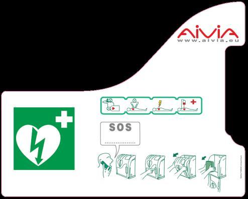
8 Installation Heating/Fan activation temperatures Entering the heating temperature (Heating option) Heating will be triggered once this threshold is matched. It will stay activated as long as the temperature has not become warmer than the threshold. Type the menu code 03, then validate : Pictograms The signs on the door of AIVIA inform you of what to do in case of emergency. You must mark the emergency number to call in the SOS pictogram if one is not already noted there. 0 3 Enter the heating threshold ( e.g. 0 C) 0 You can enter a negative temperature using the C 2 C key Entering the fan activation temperature (Heating option): Fan activation will be triggered once this threshold is matched. It will stay activated as long as the temperature has not got colder than the threshold. Check that the instructions stay clear and unmasked. Type the menu code 04, then validate : 0 4 Enter the fan activation threshold ( e.g. 35 C) 3 5 Close the AIVIA door Completely close the Aivia door. Be sure to pull the door base toward you before shutting the door 8
9 Notes 9


 It will be activated for 3 minutes.")

10 Use Night mode operation The Aivia is equipped with a light detector. In low ambient light, blinking white lights help identify the location of the Aivia. Open the Aivia door by pulling it. Visual alert is given by the blinking ot the red indicators. Heating option operation The heating option allows to maintain the AED operating temperature within working temperatures. In extreme cold temperatures, it is worthwhile checking that the alert temperature is not signaled by the flashing of the red indicators. The fan allows the heat to be extracted from the Aivia. In hot weather, it is worthwhile checking that the alert temperature is not signaled by the flashing of the red indicators Take the AED out. Alert operation Door opening alert: When the door is opened the visual alert is given by the flashing of the red indicators. If your Aivia is equipped with the siren option (Reference : X2A20-XX00 or X2A20-XX0) It will be activated for 3 minutes. Temperature alerts: The temperature alert, signaled by 4 repeated flashings of the red indicators door close is triggered when the temperature gets below the minimum temperature defined, or over the maximum temperature defined. Using the Aivia If you witness an incident needing an AED. Contact emergency services. Speak using a clear and loud voice, describe the situation without forgetting to precise the incident location. The user code will allow you to unlock the aivia. Go to the victim. Switch on the AED. Follow the AED s instructions. After using the defibrillator Do not place the defibrillator back inside the AIVIA before reactivating it. Follow the instructions in the defibrillator s manual to reset it for use. The manufacturer may be able to help reactivate the defibrillator. Please feel free to contact them. After reactivating the defibrillator, replace it inside the AIVIA using the instructions in the section "Setting up the defibrillator." Aivia maintenance Type the user code to unlock the Aivia. Wash the Aivia surfaces using a wet cloth. Wipe the Aivia with a clean & dry cloth. Do not use washing or chemical products, they could damage it. Do not rub the Aivia with any hard object, you might damage it permanently or streak it. Do not use a high pressure cleaner. 0
 at the connector block. 4. Check the insertion of the connector block. 5. Contact your distributor White indicators do not blink in night operation.")
11 In case of malfunction White indicators do not light up when the aivia is switched on.. Check the wiring polarity. 2. Check the power supply cable connection. 3. Check the voltage (24V) at the connector block. 4. Check the insertion of the connector block. 5. Contact your distributor White indicators do not blink in night operation.. Check the aivia power supply. 2. Contact your distributor Red indicators do not blink when the door is being opened.. Check the aivia power supply. 2. Contact your distributor Siren does not works when the door is opened.. Check for the siren option on the Avia identification plate. 2. Check the aivia power supply. 3. Contact your distributor I do not know my maintenance/user code.. Shut down the Aivia power supply. 2. Open the Aivia. 3. Switch on the Aivia, the white indicators will be illuminated. 4. Set the User/Maintenance code, as described in the «Setting up the Aivia» section. 5. Close the Aivia. Red indicators blink in a repeated way. Number of blinkings Cause Solution Failing memory Contact your distributor 2 Parameters lost Set-up the Aivia again 3 Temperature sensor breakdown Contact your distributor 4 Alert temperature reached Check the AED is working correctly, if needed, contact your distributor. Continuous Aivia has been opened Check AED operates correctly, and presence of all the accessories, if needed, contact your distributor. Aivia motorization doesn t work. Withdraw the cap off the aivia door, and push back the door blocking axle with a stem. Cap
12 Notes 2


13 Electrical Installation Power supply unit Mains grid 230 VAC/50Hz SELV Wiring Power supply 24VDC/3A CLASS I Power Supply Unit Must be located outside the Aivia, never installed inside the Aivia. The power supply block must include: A 0A/30mA residual current device, serving both to protect and disconnect the hardware. SELV Wiring : U000R2V Type. 2 Isolated and gained conductors,,5mm² gauge, 0 meters maximum length. For the 24V wiring use a red or brown cable. For the 0V wiring use a black or grey cable. A SELV or equivalent 24VDC +-2% / 3A Class, TT Earthing system, with limited power output, and IEC conform. The cable connecting the residual current device and the power supply must be a section of,5 mm² The mains connection must include the primary phase, neutral, and earth. The maximum full load secondary voltage drop must not exceed 2%, or 23.5V at the Aivia terminal. The power block must be dust and water proof, and ventilated**. Wires must be held against themselves by a collar at the nearest of the holding terminals. The power block wiring must conform to standards in force in the country of use. * Recommended power supply: PYRESCOM C_AL/DR ** Natural or forced convection depending on the environnment and thermal characteristics at maximum load. 3
14 Specifications Mechanical characteristics Operating temperatures and humidity : Minimum: -20ºC.(-4 F) Maximum: 55ºC. (3 F) without battery option 40 C (04 F) with battery option Relative humidity: 95% without condensation. Temperature alerts: Low temperature alert: 5 C (4 F). High temperature alert: 40ºC (04 F) Heating option: (References: X2A220-XX00 or X2A220-XX0) Heating thresold : 0 C (50 F) by default. Fan thresold: 30 C (86 F) by default. Maximum weight capacity: 5Kg ( lb). Maximum altitude: 2000 m. Weight X2A20-XX000:2,9 Kg (6.39 lb). X2A20-XX00 (siren option): 3, Kg.(6.83 lb) X2A20-XX00 (heating option): 3 Kg..(6.6 lb) X2A20-XX0 (siren & heating option): 3,3 Kg. (7.27 lb) Compliance X2A20-XX***: EN 55022:2006 EN 55024: 998/ A : 200/ A2 : 2003 EN : 2006 Composition: Door: Polycarbonate. Chassis: ABS. Square: ABS. Hatch: ABS. Technical characteristics Power supply: 24 VDC +-2% / 3A, SELV source to limited power, complies with IEC Current consumption: X2A20-XX000: Minimum: 55 ma. Maximum: 200 ma. X2A20-XX00 (siren option): Minimum: 55 ma. Maximum: 500 ma. Sound level: db / meter. X2A20-XX00(heating option): Minimum: 55 ma. Maximum: 2000 ma. X2A20-XX0 (siren and heating option): Minimum: 55 ma. Maximum: 2400 ma. Sound level: db / meter. 4
15 Notes 5
16 *A-MIP20-EN-204* 6
A-MIP 200 Installation and Operating Manual
 00 A-MIP 00 Installation and Operating Manual General Information Important Read this manual before installation and use of the Aivia. Read this section carefully and follow the instructions. The warranty
A-MIP 100 Installation and Operating Manual
 100 A-MIP 100 Installation and Operating Manual General Information Important Read this manual before installation and use of the Aivia. Read this section carefully and follow the instructions. The warranty
User Manual YDR2108. Keep this manual safe for future reference
 YDR2108 User Manual Keep this manual safe for future reference The functions and design of this product can be changed without notice for quality improvement. Please read the followings before using your
Operating instructions Page 14. Refrigerator Read the operating instructions before switching on for the first time
 Operating instructions Page 14 Refrigerator Read the operating instructions before switching on for the first time 7085 039-00 LKv 5710 Content Disposal notes... 14 Description of the appliance... 14 Safety
Wall Hung Boiler Room Thermostat OR30 OT Thermostat
 8 733 201 137-00.1O Wall Hung Boiler Room Thermostat OR30 OT Thermostat Operating Instruction 6 720 812 418 (2014/07) en 2 Contents Contents 1 Symbols and safety precautions..................................
Operating instructions Page 12
 Operating instructions Page 12 Refrigerator with explosion-proof interior container Read the operating instructions before switching on for the first time 7082 271-00 LKEXv 910 Disposal notes The appliance
CABINET RANGES FOR AUTOMATED EXTERNAL DEFIBRILLATORS (AED)
") CABINET RANGES FOR AUTOMATED EXTERNAL DEFIBRILLATORS (AED) AEDs are medical equipment that can be used by the general public Each one has an indicator light that shows the operational status. They must
CABINET RANGES FOR AUTOMATED EXTERNAL DEFIBRILLATORS (AED) AEDs are medical equipment that can be used by the general public Each one has an indicator light that shows the operational status. They must
PROTECTION CABINETS SUPERVISION CABINETS FOR AUTOMATIC EXTERNAL DEFIBRILLATORS (AEDs)
") PROTECTION CABINETS SUPERVISION CABINETS FOR AUTOMATIC EXTERNAL DEFIBRILLATORS (AEDs) FEATURES OF AIVIA PROTECTION MODELS H : 423 mm The Aivia range has been designed and manufactured by the French company
PROTECTION CABINETS SUPERVISION CABINETS FOR AUTOMATIC EXTERNAL DEFIBRILLATORS (AEDs) FEATURES OF AIVIA PROTECTION MODELS H : 423 mm The Aivia range has been designed and manufactured by the French company
INSTRUCTION MANUAL FOR: WIRELESS SECURITY STARTER KIT MODEL NO: SWSKIT
 INSTRUCTION MANUAL FOR: WIRELESS SECURITY STARTER KIT MODEL NO: SWSKIT B. Operation i. Powering up the Key Fob Remote Control ii. Enrolling the Remote Control onto the Smart Panel iii. Operating the Key
User Manual Keep this manual safe for future reference
 YDM 3109 User Manual Keep this manual safe for future reference ISL-1213-00 rev.1 The functions and design of this product can be changed without notice for quality improvement. Chinese manual is from
User Manual YDM The functions and design of this product can be changed without notice for quality improvement. Chinese manual is from 33 page.
 YDM 3109 User Manual Keep this manual safe for future reference The functions and design of this product can be changed without notice for quality improvement. Chinese manual is from 33 page. Ver. PMU-0904-01
USER MANUAL QSDL503AD Intelligent Auto-Dial Alarm System
 USER MANUAL QSDL503AD Intelligent Auto-Dial Alarm System Rev 10.28.2009 TABLE OF CONTENTS Section 1: USAGE... 1 Section 2: FEATURES... 1 Section 3: PACKAGE CONTENTS... 1 Section 4: SYSTEM INSTALLATION...
ETSA380MF SHOWN WARNING. shall be used ONLY on approved vehicles. It is the sole responsibility of the user of these devices to ensure compliance.
 WARNING: Warning devices are strictly! WARNING Sirens produce loud sounds that may damage hearing: - Roll up windows. - Wear hearing protection. - Use only for emergency response. - Avoid exposure to siren
MODEL B2 INSTALLATION MANUAL
 RELEASE DEVICES GENERAL DESCRIPTION MODEL B2 INSTALLATION MANUAL S/N: The B2 Series Time Delay Release Devices are UL Listed, Canadian Listed, and CSFM Listed for use on rolling doors, single-slide and
G34 AU1B (External Ultrasonic Sensor) Version 3
 Version 3") Car Alarm Series 3 B 4 Buttons G34 AU1B (External Ultrasonic Sensor) Version 3 24 CAR ALARM GENIUS Series 3B 4 Buttons G34 AU1B (External Ultrasonic Sensor) Module controlled using Micro-Processor 2 Transmitters
Car Alarm Series 3 B 4 Buttons G34 AU1B (External Ultrasonic Sensor) Version 3 24 CAR ALARM GENIUS Series 3B 4 Buttons G34 AU1B (External Ultrasonic Sensor) Module controlled using Micro-Processor 2 Transmitters
Zerio Plus EDA-D6000 Radio Combined Heat Detector and Sounder Installation Instructions
 Zerio Plus EDA-D6000 Radio Combined Heat Detector and Sounder Installation Instructions EN54-3:2001+A1:2002+A2:2006 EN54-5:2000+A1:2002 EN54-25:2008 0359 Electro Detectors Ltd. Electro House Edinburgh
DIGITAL. Operation & Installation Guide. Read These Instructions Very Carefully! Home and Office Security Safes MFFS2054DF84DF18DFE0809 ENGLISH
 Operation & Installation Guide MFFS2054DF84DF18DFE0809 ENGLISH Model 2054DF Model 2084DF Model 2118DF DIGITAL Read These Instructions Very Carefully! Home and Office Security Safes Index Overview of Your
Operator s Manual. The Quietek
 Operator s Manual The Quietek Congratulations! Congratulations on your purchase of the Quietek euthanization system. Please read this operator s manual which explains proper operation of the instrument.
TFD-1 Installation & User s Guide
 TFD-1 Installation & User s Guide TABLE OF CONTENTS CHAPTER 1 - INTRODUCTION... 4 1.1 GENERAL...4 1.2 DESCRIPTION...4 CHAPTER 2 - INSTALLATION... 5 2.1 UNPACKING...5 2.2 MOUNTING...5 2.3 SWITCH SETTINGS...6
Curv-infrared.com. The Smarter Way. To Heat Your Home. Installation & Operating Instructions For Cürv, Flat, Towel Rail and Mirror Infrared Heaters
 Curv-infrared.com The Smarter Way To Heat Your Home Installation & Operating Instructions For Cürv, Flat, Towel Rail and Mirror Infrared Heaters Safety Precautions Important Notice To Purchaser Before
MOBILE CALL GSM Alarm System User s Manual
 MOBILE CALL GSM Alarm System User s Manual Profile For a better understanding of this product, please read this user manual thoroughly before using it. Contents Function Introduction (3) Alarm Host Diagram
Smart Home Outdoor Siren
 Security Made Smarter Smart Home Outdoor Siren QUICK START GUIDE EN 1 Welcome! Thank you for choosing the Smart Home Outdoor Siren - the ideal addition to your Swann Smart Home system. Setting up the Outdoor
FLCH4R Garage and Utility Electric Heater
 FLCH4R Garage and Utility Electric Heater Installation, Operation & Maintenance Instructions Model No. Volts Amps Watts BTU/HR Phase High Low High Low High Low Min Fuse Size* FLCH4R 208 17.3 8.66 3600
Digital Programmable
 www.geappliances.com Digital Programmable Thermostats Operating Instructions Auto Changeover..........10 Day/Time Setting Mode.....6 Default Mode...............4 Fan Control...............10 Hold and Temporary
USER GUIDE WIRE-FREE HOME PROTECTION SYSTEM AG100+ CONTENTS
 CONTENTS USER GUIDE WIRE-FREE HOME PROTECTION SYSTEM AG00 Section Getting started. General system overview. Introduction to the system. Items included with the system. Introduction to the Smart Panel.5
RELEASE DEVICE CONTROLS
 RELEASE DEVICE CONTROLS RELEASE DEVICE MODEL C+ INSTALLATION MANUAL UL LISTED CANADIAN LISTED CSFM: 7300-48:00 GENERAL DESCRIPTION: MADE IN THE U.S.A. S/N: The LM0-C+ Release Device/Control Panel is a
LZR -I30. max. detection range of 30 ft x 30 ft LASER SCANNERS FOR INDUSTRIAL DOORS LZR-I Page 1 of 12
 EN LZR -I30 LASER SCANNERS FOR INDUSTRIAL DOORS max. detection range of 30 ft x 30 ft 75.5667.07 LZR-I30 0509 Page of SAFETY The device contains IR and visible laser diodes. IR laser: wavelength 905nm;
Design Manual Installation Operation Maintenance
 Design Manual Installation Operation Maintenance Model FT194 UV/IR Portable Flame Detector Test Lamp 23282 Mill Creek Drive, Suite 215 Laguna Hills, CA 92653 USA +1.949.583.1857 Phone +1.949.340.3343 Fax
ELIMINOSTAT DC-ESR-CL-S2
 Static Clean Instruction Manual DC Voltage Application Method Static Eliminators Static Eliminator with Integral Power Supply ELIMINOSTAT DC-ESR-CL-S2 Thank you for purchasing the Static Eliminator ELMINOATAT
LZR -I100/ -I110. LASER SCANNERS for industrial doors. User s Guide for product version 0600 and more
 EN LZR -I00/ -I0 LASER SCANNERS for industrial doors I00: max. detection range of 9.9 m x 9.9 m I0: max. detection range of 5.0 m x 5.0 m User s Guide for product version 0600 and more SAFETY The device
DSGH. Radiation-Based Detector with GEN2000 Electronics for Density Measurement QUICK REFERENCE GUIDE
 DSGH Radiation-Based Detector with GEN2000 Electronics for Density Measurement QUICK REFERENCE GUIDE Revision History Revision History Version of manual Description Date 1.0 Initial release 051025 1.1
Towel Warmer MAKE EVERYDAY A SPA DAY
 Towel Warmer MAKE EVERYDAY A SPA DAY TABLE OF CONTENTS Warnings and Cautions....1 FCC Information...4 Location of Parts and Controls...6 Set Up... 7 Using the Towel Warmer....8 Selecting the Timer...9
Mark 25 Ultrapure Water Conductivity Analyzer
 Martek Instruments, Inc. Mark 25 Ultrapure Water Conductivity Analyzer Instruction Manual WARRANTY POLICY Unless otherwise stated, MARTEK INSTRUMENTS, INC. warrants this equipment to be free from defects
For Android devices MYQ-G0301 MYQ-G0301C MYQ-G0301D MYQ-G0301LA
 Smart Smart Garage Garage Hub Hub Manual Manual For Android devices MYQ-G0301 MYQ-G0301C MYQ-G0301D MYQ-G0301LA by Before You Start To reduce the risk of SEVERE INJURY to persons: DO NOT enable the MyQ
PHOTOVOLTAIC HEAT CONTROLER PVHC 2.01 USER MANUAL
 USER MANUAL CONTENT CONTROL ELEMENTS AND CONNECTIONS... 3 HOW IT WORKS... 4 INSTALLATION PROCEDURE, SWITCHING ON THE DEVICE... 5 CONNECTION DIAGRAM... 6 USER MENU... 7 SPECIFICATIONS... 11 EU Declaration
CPS-1 USER S MANUAL AIR INLET / CURTAIN CONTROL
 CPS-1 USER S MANUAL AIR INLET / CURTAIN CONTROL temperature / static pressure DIFF Opn Clo ALARM HI F2 DELAY ALARM LO OPEN DELAY CLOSE ADJUST Varifan + CPS-1 CPS-1 Although the manufacturer has made every
Installation and Operation Manual. Model: STI TRIGGERED OUTPUT PLUG 12VDC, 75mA, 3 SEC. EMBOSSED PROGRAMMING
 EMBOSSED PROGRAMMING SWITCHES 1-8 ANTENNAS ZONES: LEFT BUTTON CALL Embossed Programming Instructions: Installation and Operation Manual STI 8-Channel 1 - MIRROR MASTER OFF/ON RIGHT BUTTON FRONT COVER RESTORE
DIGITAL STEEL FIRE & SECURITY
 Models 2111-2115 DIGITAL STEEL FIRE & SECURITY Read this manual carefully and never store it inside the safe! Digital Steel Fire & Security Safe Models 2111-2115 PACKAGE CONTENTS 1 Digital Steel Fire &
Instruction Manual. Self-Leveling Combination Cross-Line Laser and Five-Beam Laser Dot Model No &
 6339H_Manuals 10/24/12 12:56 PM Page 1 Self-Leveling Combination Cross-Line Laser and Five-Beam Laser Dot Model No. 40-6685 & 40-6687 Instruction Manual Congratulations on your choice of this Self-Leveling
ITEM # , , PAWTUCKET CEILING FAN MODEL #40958, 40959, 40047
 ITEM #0803775, 0721899, 0807427 PAWTUCKET CEILING FAN MODEL #40958, 40959, 40047 Harbor Breeze is a registered trademark of LF, LLC. All Rights Reserved. Español p. 20 ATTACH YOUR RECEIPT HERE Serial Number
For ios devices MYQ-G0301 MYQ-G0301C MYQ-G0301-D MYQ-G0301LA
 Smart Smart Garage Garage Hub Hub Manual Manual For ios devices MYQ-G0301 MYQ-G0301C MYQ-G0301-D MYQ-G0301LA by Before You Start To reduce the risk of SEVERE INJURY to persons: DO NOT enable the MyQ Smart
The most user friendly Security Alarm System L S Section 1 Overview of System Section 2 Planning your Installation
 The most user friendly Contents Section 1 Overview of System 1.1 Kit Contents 1.2 Tools Required 1.3 System Features Security Alarm System L S 4 0 0 Section 2 Planning your Installation 2.1 Location of
External Wireless Sounder
 External Wireless Sounder Model: WL RWS401 Installation and Programming Instructions Table of Contents Introduction... 3 Operational Functions... 3 Alarm / Tamper Indication... 3 Low Battery Indication...
Operating instructions Page 14. Refrigerator Read the operating instructions before switching on for the first time
 Operating instructions Page 14 Refrigerator Read the operating instructions before switching on for the first time 7084 309-00 LKUv Disposal notes The appliance contains reusable materials and should be
Crypto-Lock. Model CC-8521B Updated 7/17. Access Control System. MONITEQ, Inc. INSTRUCTION MANUAL
 Crypto-Lock Model CC-8521B Updated 7/17 Access Control System INSTRUCTION MANUAL MONITEQ, Inc. 2 TABLE OF CONTENTS 1. INTRODUCTION..4 2. SPECIFICATIONS.....6 3. SUPPLIED EQUIPMENT.. 6 4. FUNCTIONS OF CONTROLS
Instruction Manual. Model AccuPlate Hotplate AccuPlate Stirrers AccuPlate Hotplate Stirrer 12/10 CLS-EQ-LHP01REV
 Instruction Manual Model AccuPlate Hotplate AccuPlate Stirrers AccuPlate Hotplate Stirrer 12/10 CLS-EQ-LHP01REV2 9296050000 About This Manual This manual is designed to assist you in optimal usage of your
Alarm System SECURE AS 302
 Alarm System SECURE AS 302 Operating Manual SECURE Light app now available! Table of Contents Before You Start.................................. 4 User Information....................................4
MGC Dock User s Manual
 User s Manual Contents Warnings Statements/Avertisseement... 3 READ FIRST BEFORE OPERATION... 3 Description... 4 Basic Operation... 5 Clip Dock Components... 5 LEDs... 5 User Operation... 6 Turning the
PORTABLE AIR CONDITIONER (LOCAL)
") EN PORTABLE AIR CONDITIONER (LOCAL) OPERATING INSTRUCTIONS Read the instructions carefully before operating the appliance or carrying out maintenance work. Observe all the safety instructions; failure
EN PORTABLE AIR CONDITIONER (LOCAL) OPERATING INSTRUCTIONS Read the instructions carefully before operating the appliance or carrying out maintenance work. Observe all the safety instructions; failure
Operator s Manual. The Bullet Blender 50 BB50-AU, BB50-DX. Contents. Congratulations!
 Operator s Manual The Bullet Blender 50 BB50-AU, BB50-DX Congratulations! Congratulations on your purchase of a Bullet Blender 50 by Next Advance, Inc., for mixing, lysing, disrupting, and homogenizing
Instructions for the fan motor control system with integrated wiring terminals SILVER C
 Instructions for the fan motor control system with integrated wiring terminals SILVER C 1. General The motor control system is used for controlling the type EC, 0.41-10 kw fan motors in the SILVER C units.
Installing the Cisco ONS FAP-4 Fuse Alarm Panel
 Installing the Cisco ONS 15454-FAP-4 Fuse Alarm Panel Product Number: 15454-FAP-4= This document explains how to install, test, operate, and maintain the Cisco ONS 15454-FAP-4 fuse alarm panel. This document
Operating instructions Page 14. Refrigerator Read the operating instructions before switching on for the first time
 Operating instructions Page 14 Refrigerator Read the operating instructions before switching on for the first time 7085 473-00 MKv Content Disposal notes... 14 Description of the appliance... 14 Safety
Instruction Manual. Self-Leveling Combination Cross-Line Laser and Five-Beam Laser Dot Model No , &
 1622i_Manuals 12/14/16 12:52 PM Page 1 Self-Leveling Combination Cross-Line Laser and Five-Beam Laser Dot Model No. 40-6685, 40-6687 & 40-6688 Instruction Manual Congratulations on your choice of this
Thermostats. Digital Programmable. GEAppliances.com
 GEAppliances.com Digital Programmable Thermostats Owner s Manual & Installation Instructions RAK148P2 RAK164P2 Configuration Mode...8 9 Important Safety Information... 2 Installation Instructions... 4
Network Camera. Quick Guide DC-T1233WHX. Powered by
 Network Camera Quick Guide DC-T1233WHX Powered by Safety Precautions WARNING RISK OF ELECTRIC SHOCK DO NOT OPEN WARNING: TO REDUCE THE RISK OF ELECTRIC SHOCK, DO NOT REMOVE COVER (OR BACK). NO USER-SERVICEABLE
DOL 31 Speed Controller Technical User Guide
 Technical User Guide For other language variants of this document we refer to your local dealer or http://docs.skov.com/1158. Available from April 2016. 612061 2016.09.20 Technical User Guide Program
Installation and ZONES: Operation Manual. Model: ON STI-34108
 N.O. COM N.C. + 12 V - IN + 12 V - OUT 500 ma 300 ma PLUG IN ADAPTER 12 V 500mA Trigger Output 12 V 75mA N.O. COM N.C. + 12 V - IN + 12 V - OUT 500 ma 300 ma PLUG IN ADAPTER 12 V 500mA Trigger Output 12
FIREFLY II PLUS RELEASE DEVICES INSTALLATION MANUAL
 FIREFLY II PLUS RELEASE DEVICES INSTALLATION MANUAL MADE IN THE U.S.A. U.L. LISTED CANADIAN LISTED CSFM: 7300-1418:100 GENERAL DESCRIPTION SERIAL NUMBER The Cookson Company FIREFLY II PLUS Time Delay Release
Refresh & Clean Carpet Washer
 Refresh & Clean Carpet Washer Model Number: RHCC5001 220-240 V~, 50/60Hz, 500-600W For Customer Services & Spare Parts please call 0345 209 7461 Opening times: Monday - Friday 8am 8pm & Saturday 9am 1pm
Total Connect Box. User manual
 Total Connect Box User manual 1 Congratulations on your purchase of the Honeywell Total Connect Box security system. To make the best out of your system we advise you to read this manual carefully. This
2-Port alarmcharge Hub - Manual
 Installation Manual 1. What s in the box 2. Fixture preparation 3. Mounting 4. Mechanical 5. Device power Operation Manual 6. Device connectors and connections 7. Alarming remote control 8. Safety 9. Warranty
WIRELESS MEASUREMENT SYSTEM OF GAS BOTTLES FILLING LEVEL WITH GAS LEAK DETECTION GMS 300. User Manual
 EN WIRELESS MEASUREMENT SYSTEM OF GAS BOTTLES FILLING LEVEL WITH GAS LEAK DETECTION GMS 300 User Manual EN Wireless measuring pad Wireless measurement display Michal Provázek s.r.o. I.P. Pavlova 126 779
GB Operating instructions
 Scope of delivery/device components 1 Carrier for suction nozzles 2 Dust bin 3 Release button (dust bin) 4 On/Off Switch 5 Motor casing 6 Rechargeable battery 7 Release buttons rechargeable battery 8 Swing
Model Instruction Manual. Coleman Limited One-Year Warranty. 26 Quart Power Cooler. For use with 12 VDC only
 Coleman Limited One-Year Warranty The Coleman Company, Inc. ( Coleman ) warrants that for a period of one year from the date of original retail purchase, this product will be free from defects in material
DDS-SSENSOR - INSTALLATION MANUAL. Installation Manual DDS-S SENSOR
 Installation Manual DDS-S SENSOR 1 TRANSLATED DOCUMENT This manual has been compiled according to standard UNE-EN-ISO 12100. INSTALLATION MANUAL DDS-S SENSOR Read thoroughly all of these instructions before
Suits all KPF849 models
 Kambrook - Australia Ground Floor, Suite 2, 170-180 Bourke Rd Alexandria NSW 2015, Australia Locked Bag 2000 Botany NSW 1455 Customer Service Line 1300 139 798 Customer Service Fax 1800 621 337 www.kambrook.com.au
Self-Setting Clock Radio
 Self-Setting Clock Radio Just plug it in it sets itself TimeSmart table of contents Cautions and Warnings................................................. 2-6 Location of Controls....................................................
SAFETY MANUAL. X2200 UV, X9800 IR, X5200 UVIR SIL 2 Certified Flame Detectors
 SAFETY MANUAL X2200 UV, X9800 IR, X5200 UVIR SIL 2 Certified Flame Detectors SAFETY-CERTIFIED Flame DETECTORs This manual addresses the specific requirements and recommendations applicable to the proper
380 SERIES REMOTE SIREN ETSA380R
 ! WARNING Sirens produce loud sounds that may damage hearing: - Roll up windows. - Wear hearing protection. - Use only for emergency response. - Avoid exposure to siren sound outside of vehicle. Please
BSR Addressable Fire Detection control panel. Installation operation manual
 BSR-1116 Addressable Fire Detection control panel Installation operation manual ATTENTION!!! READ THE MANUAL BEFORE THE INSTALLATION AND PAY ATTENTION TO PARAGRAPH 2.6.3 AND 2.6.4. Page 2 from 36 Contents
SAFETY MANUAL. Multispectrum IR Flame Detector X3301
 SAFETY MANUAL Multispectrum IR Flame Detector X3301 SAFETY-CERTIFIED MODEL X3301 MULTISPECTRUM INFRARED DETECTOR This manual addresses the specific requirements and recommendations applicable to the proper
1U ULTRA Compact System
 en atel Supervisory Module SM32 Load 60 00 A IE C60947-2 G B140 4 8.2 CHNT NB1-63 C32 23 0/40 0 V e NaT el OK enatel RM 1848 enatel RM 1848 Battery 60 00A IE C60947-2 G B1 4 04 8.2 CHNT NB 1-63 C32 23
Operating instructions 2-channel code lock. Item No
 Operating instructions 2-channel code lock Item No. 1560346 Table of contents Page 1. Introduction...4 2. Explanation of symbols...4 3. Intended use...5 4. Delivery content...5 5. Safety instructions...6
MST-1. Varifan USER S MANUAL MST-1 ADJUST. 9 per day HI F2. DIFF on off TIMER. reduc.
 USER S MANUAL ALARM HI F2 COOL / HEAT ALARM LO DIFF on off PERIOD TIMER L IMIT reduc. 9 per day 88 ADJUST Varifan + Although the manufacturer has made every effort to ensure the accuracy of the information
Projection Alarm Clock USER GUIDE
 Projection Alarm Clock USER GUIDE Jazwares, Inc. 2012 CONTENTS Please read the instructions along with the Alarm Clock carefully before you use it, so that you can operate it conveniently. WELCOME, Warnings
OWNER S MANUAL. R 410A Ductless Split System Air Conditioner and Heat Pump
 R 410A Ductless Split System Air Conditioner and Heat Pump Models DLC4(A/H) Outdoor Unit, DLF4(A/H) Indoor Unit Sizes 9K, 12K, 18K, 24K, 30K and 36K Please read the operating instructions and safety precautions
! WARNING To avoid risk of electrical shock, personal injury or death; disconnect power to oven before servicing, unless testing requires it.
 Electric Wall Oven Technical Information JJW8627DD*, JJW8630DD*, JJW9627DD*, JJW9630DD*, JJW9827DD*, JJW9830DD* Refer to Service Manual 16022506 for detailed installation, operating, testing, troubleshooting,
Operator: Save these instructions for future use!
 F145-1328/F145-1378 Indoor /Outdoor INSTALLATION INSTRUCTIONS Operator: Save these instructions for future use! FAILURE TO READ AND FOLLOW ALL INSTRUCTIONS CAREFULLY BEFORE INSTALLING OR OPERATING THIS
Alarm Tone Generator Model AG17
 Alarm Tone Generator Installation & Operation P005089 Rev. C 150930 9/30/2015 12:25 PM Ph: 403.258.3100 \ email:info@guardiantelecom.com \ www.guardiantelecom.com Table of Contents Package Contents...
275HVD NON-CONTACT, HIGH VOLTAGE DETECTOR DETECTOR DE ALTA TENSIÓN SIN CONTACTO
 99 Washington Street Melrose, MA 02176 Phone 781-665-1400 Toll Free 1-800-517-8431 Visit us at www.testequipmentdepot.com 275HVD NON-CONTACT, HIGH VOLTAGE DETECTOR DETECTOR DE ALTA TENSIÓN SIN CONTACTO
Multi-Gas-Controller MGC2
 Page 1 Aug. 2018 Gas measuring, monitoring and warning controller based on state-of-the-art micro-technology for continuous monitoring of the ambient air to detect toxic and combustible gases, refrigerants
Ceiling-Mounted Motion Detector. 752/CD, 752/CP, 752/CU and 752/Cx180. Installation Instructions
 Ceiling-Mounted Motion Detector 752/CD, 752/CP, 752/CU and 752/Cx180 Installation Instructions Contents 1.0 Description...3 1.1 Contents of the Box...3 2.0 Safety...4 3.0 Coverage Patterns...4 3.1 PIR
VX SERIES Wireless Thermostat with Occupancy Sensor
 VX SERIES Wireless Thermostat with Occupancy Sensor INSTRUCTION MANUAL Table of Contents Thermostat Installation... 7 Installing the Wireless Control Card...8 Mounting the thermostat to the wall...9 Thermostat
Table of Content LT 5165-UL
 Table of Content LT 565-UL. User manual.... Legal regulations... 3. Safety instructions... 3 4. Technical information... 4 5. Technical data... 4 6. Performance Graph... 5 7. Mounting... 6 8. Mounting
Protégé Eclipse LED Keypad User Manual PRT-KLES
 Protégé Eclipse LED Keypad User Manual PRT-KLES The specifications and descriptions of products and services contained in this manual were correct at the time of printing. Integrated Control Technology
Auto Dialer. Manual E-921APQ E-921GPQ
 Troubleshooting: Auto dialer will not arm/disarm Auto dialer will not dial out Unit doesn t respond to a call-back Difficulty in activating room monitor by telephone remote control Make sure that you have
FIRERAY 5000 range USER GUIDE
 FIRERAY 5000 range USER GUIDE 0044-003-04 IMPORTANT PLEASE NOTE: The beam path MUST be kept clear of obstructions at all times! Failure to comply may result in the Detector initiating a Fire or Fault signal.
52 CEILING FAN. Owner s Manual Models #50336, 50337
 52 CEILING FAN Owner s Manual Models #50336, 50337 If a problem cannot be remedied or you are experiencing difficulty in installation, please contact the Service Department: 1-877-706-3267, 9 a.m.- 5 p.m.
DLC Instruction Manual. Light Curing Machine MODEL. Table of Contents
 Light Curing Machine Table of Contents Precautions for Electrical >>>>>>>>>>> 1 Equipment in Use Precautions >>>>>>>>>>>>>>>>>>>> 2 Recommended Procedure when >>>>> 4 Opening Product Packaging Part Names
External Wireless Sounder
 External Wireless Sounder WL S50 Installation and Programming Instructions 2 Wireless Sounder Instructions Table of Contents Introduction... 4 Operational Functions... 4 Alarm / Tamper Indication...4 Low
Models NFPA 1221-A, NFPA 1221-B Public Safety DAS Annunciator Panel. Revision E 61117
 Models NFPA 1221-A, NFPA 1221-B Public Safety DAS Annunciator Panel Revision E 61117 CAUTION: (Read This First) This panel has been designed to make it nearly bullet proof to mistakes made when wiring
HOME AUTOMATION, INC. Lumina and Lumina Pro Lighting and Automation System. Quick-Start Installation Guide
 HOME AUTOMATION, INC. Lumina and Lumina Pro Lighting and Automation System Quick-Start Installation Guide Document Number 44I00-1 Rev. 2.12 February, 2006 For complete operation and programming instructions,
SPA DE USO PRIVADO SPA FOR PRIVATE USE SPA POUR UN USAGE PRIVÉ SPA FÜR PRIVATE NUTZUNG SPA PER USO PRIVATO SPA PARA USO PRIVADO SPA VOOR PRIVE-GEBRUIK
 SPA DE USO PRIVADO SPA FOR PRIVATE USE SPA POUR UN USAGE PRIVÉ SPA FÜR PRIVATE NUTZUNG SPA PER USO PRIVATO SPA PARA USO PRIVADO SPA VOOR PRIVE-GEBRUIK MANUAL DE INSTALACIÓN INSTALLATION MANUAL MANUEL D
FreezeAlarm Dialer FA-700 Installation and Operations Manual
 FreezeAlarm Dialer FA-700 Installation and Operations Manual Emerson Control Products Inc. 1724 Lake Drive West Chanhassen, MN 55317 Document No. 42420079B Table of Contents Cautions and warnings... 4
Operating instructions Page 14
 Operating instructions Page 14 Refrigerator with explosion-proof interior container Read the operating instructions before switching on for the first time 7085 479-00 LKexv Inhalt Disposal notes... 14
Miniature Thermoelectric Cooler Controller MTCC-01 user's guide
 Miniature Thermoelectric Cooler Controller MTCC-01 user's guide 1 Table of Contents 1. Warranty... 3 2. MTCC-01-xxx overview... 4 2.1. MTCC-01-xxx specification... 4 2.2. TE cooled detector temperature
System. For a better understanding of this product, please read this user manual thoroughly before using it.
 GSM Alarm System User s Manual For a better understanding of this product, please read this user manual thoroughly before using it. Chapter 1. Features Chapter 2. Control Panel Introduction Chapter 3.
IMPORTANT. PLEASE NOTE: The infrared beam path MUST be kept clear of obstructions at all times!
 USER GUIDE English IMPORTANT PLEASE NOTE: The infrared beam path MUST be kept clear of obstructions at all times! Failure to comply may result in the Detector initiating a Fire or Fault signal. Contents
50M Integrated Single or Two-Stage HSI Integrated Furnace Control Kit INSTALLATION INSTRUCTIONS
 50M56-743 Integrated Single or Two-Stage HSI Integrated Furnace Control Kit INSTALLATION INSTRUCTIONS FAILURE TO READ AND FOLLOW ALL INSTRUCTIONS CAREFULLY BEFORE INSTALLING OR OPERATING THIS CONTROL COULD