DDS-SSENSOR - INSTALLATION MANUAL. Installation Manual DDS-S SENSOR
|
|
|
- Baldric Patterson
- 5 years ago
- Views:
Transcription


1 Installation Manual DDS-S SENSOR 1


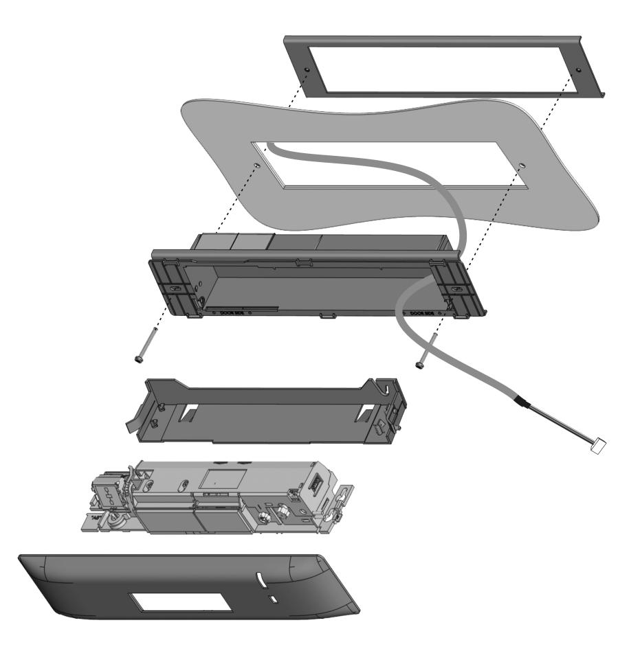
2 TRANSLATED DOCUMENT This manual has been compiled according to standard UNE-EN-ISO INSTALLATION MANUAL DDS-S SENSOR Read thoroughly all of these instructions before using the unit. This manual includes all the necessary information required to install the product Keep this manual in a safe place for future reference. CONTENTS 1 DESCRIPTION 3 USER MENU 4 TROUBLESHOOTING 5 INSTALLATION CHECKLIST 2 COMMISSIONING 2.1 MOUNTING 6 MAINTENANCE 6.1 MAINTENANCE TO BE CARRIED OUT BY THE USER 6.2 MAINTENANCE RESTRICTED TO THE MANUFACTURER 7 DECLARATION CE OF CONFORMITY 1 DESCRIPTION The AIR DPS Sensor is an electro-sensitive device for the detection of individuals, specifically designed to provide safety to Manusa sliding doors. This sensor complies with all the requirements specified in the Standard EN LCD screen 4 Cover 7 Infrared angle setting button 2 Infrared curtain setting 5 Main connector 3 Infrared lenses 6 Main settings button 1.1 SYMBOL DESCRIPTION The symbol that appear in this manual is the next: IMPORTANT WARNING. Strictly adhere to the indications provided with this symbol. 2


3 1.2 TOOLS REQUIRED Tape measure Flathead screwdriver Spirit level Drill Bits: Ø 3 Ø 8 Drill Mounting template 1.3 SAFETY INSTRUCTIONS All national and international provisions relating to door safety must be observed. The installation and commissioning of the sensor should only be carried out by authorised technical staff. Any servicing or repair works on the sensor should only be carried out by manusa. Any other use of the device different from its intended purpose shall be excluded from the manufacturer s guarantee. This device may only be operated with protective low voltage (SELV) with safe electrical insulation. The installing company shall be responsible for the correct installation of the sensor and the door safety elements. The manufacturer shall not be liable for incorrect sensor installations or inappropriate settings which have not been implemented by manusa. When handling the sensor, great care must be taken in order not to interfere with its correct operation. 3
4 1.4 TECHNICAL DATA Power supply 12V - 30V DC +/-10% To be operated from SELV-compatible power supplies only Power consumption < 2.5W Mounting height Operating temperature Protection class Noise Useful life Applicable directives Detection mode 2 to 3.5 m (internal regulations may affect the acceptable mounting height) -25 up to 55 C; 0 at 95% RH, without condensation IP54 <70 db 20 years EMC 2004/108/EC; MD 2006/42/EC; ROHS 2002/95/EC Presence Red Technology Input Output Infrared active with environmental scanning Spot: 5cm x 5cm (typical) Spots per curtain: max 24. Number of curtains: 2 Pulse polarity: positive or negative (adjustable) Impedance: Positive pulse: 2K to earth 470R to the + of the power source Pulse voltage: from 6V to 30V Pulse duration: from 4µs to 500µs Work cycle: Max. 50% Pulse polarity: negative Level: No detection: Pulse between the + of the power source and 0V Detection: the + of the power source Topology: open collector with 4.7K to 3.3V Maximum sink current: 25mA with 1K external resistance towards 24V Optional: Solid-state relay (without potential or polarity) Maximum current output: 100mA Max. circuit-breaking capacity: 42V AC/DC Certification EN EN ISO :2008 PL c (on the condition that the door controller monitors the sensor at least once for every door cycle) EN 16005:2012 Chapter DIN ;2010 Chapter BS :1996 Chapter 8.1 Reaction time <200ms (max. 500ms) Infrared angle points setting -7 up to +3.5º 4


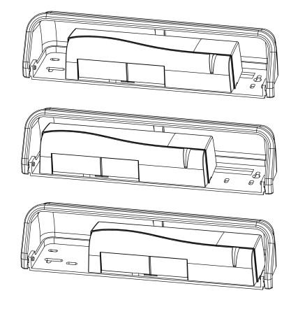
5 2 COMMISSIONING The recommended commissioning sequence is as follows: installation, connection, start-up and settings. 2.1 MOUNTING STANDARD MOUNTING 1. Remove the protective cover 2. Connect the cable 3. Position the drilling template 4. Drill the holes and remove the template 5. Pass the cable through and install the sensor Max 5cm SURFACE MOUNTING (OPTIONAL) 136 mm MOUNT DISMOUNT Presionar 1 Slide 2 Clip 1 Unclip 5


6 2.1.3 CEILING MOUNTING (OPTIONAL) 1 Cut 2 Screw together 3 Clip 4 Clip 5 Unclip 6 Clip 7 Unclip 8 Clip MOUNTING WITH RAIN PROTECTION (OPTIONAL) 6
7 2.2 WIRING 12-30V AC-DC * SENSOR VERDE MARRÓN AMARILLO BLANCO ROSA GRIS VIOLET POWER SUPPLY OPENING INPUT SAFETY OUTPUT SAFETY INPUT PULL-UP** *Output condition when the sensor is in operation. ** Bravo only, connect to 12V CONNECTION TO VISIO OPERATOR FOR OPENING PROTECTION a Connection to a sensor Sensor DDS-S Green Brown Pink Grey Note: Configure the following parameter: PULSE INPUT = positive b Connecting two sensors Sensor 1 Sensor 2 Green Brown Green Brown DDS-S Pink Grey Pink Grey DDS-S Note: Configure the following parameters: Sensor 1: PULSE INPUT = positive Sensor 2: PULSE INPUT = negative 7
8 2.2.2 CONNECTION TO VISIO OPERATOR FOR CLOSING PROTECTION Sensor DDS-S Green Brown Pink Grey Note: Configure the following parameter: PULSE INPUT = positive CONNECTION TO BRAVO OPERATOR FOR CLOSING PROTECTION Note: Configure the following parameters: PULSE INPUT = positive Sensor DDS-S Green Brown Pink Grey Violet CONNECTION TO ACTIVA OPERATOR FOR CLOSING PROTECTION Note: Configure the following parameters: PULSE INPUT = positive Sensor Green DDS-S Brown Pink Gris 8

 WIDTH *Visibility depends")


9 2.3 SAFETY FIELD SETTING - INFRARED CLOSER ANGLE FARTHER 9 cm x2 1 Press twice to activate the 2 If necessary, adjust the angle of the visible spot. infrared curtains (from -7º to +4º) WIDTH *Visibility depends on external conditions. If the spots are not visible, the Spotfinder helps to locate the position of the curtains. **The distance between the inner curtain of the inside door sensor and the inner curtain of the outside door sensor should always be less than 20cm The distance up to the door leaf depends therefore on the thickness of the door leaf. Possible additional settings through the LCD. Part of the emitted field can be covered in order to reduce the detection field. The position of the arrow determines the field width. Always check the field width with a piece of paper and not with the Spotfinder, that detects the entire emitted field. The size of the detection fields varies depending on the mounting height and the settings of the sensor. The sensor should cover the whole travel path of the door leaf/leaves. To verify, use the reference body as per EN (reference body dimensions: 700x300x200mm). Cuerpo de referencia 2.4 OTHER SETTINGS Set the sensor by LCD or choose one of the presettings: 1.- STANDARD: indoor mounting Presettings Standard 2. CRITICAL ENVIRONMENT: critical or outside installations Presettings Critical env. 3. SHOPPING STREET: Installations in narrow streets with pedestrian traffic Presettings Shopping str. 9
10 4 2.5 SETUP After SETUP, check that the installation operates correctly before signing off on the setup process. IMPORTANT! After DDS-S setup do a self learning procedure for door automation (Visio) QUICK SETUP = OK 2s 1 Vacate the detection field 2 Press for 2s 3 When the LED switches off, the sensor is ready for use ASSISTED SETUP 4s 1 Vacate the detection field 2 Press for 4s 3 The door performs an opening manoeuvre. = OK 4 The door performs an closing manoeuvre. 5 When the LED switches off, the sensor is ready for use 10


11 2.6 USING THE LCD SCREEN INSTRUCTIONS DURING NORMAL OPERATION Opening impulse Safety To adjust the contrast, simultaneously press and turn the grey button Negative display = Active output FACTORY VALUE vs. SAVED VALUE Displayed value = Factory value Displayed value = Saved value NAVIGATING THE MENUS 30s 1 Press to access the menu 2 Enter password if required. Not during the first minute after the detector comes ON 3 Select language before entering the first menu. During the first 30s after switching the sensor on or later in the diagnostics menu. 4 Scroll through the menu items 5 Select BACK to return to the 6 Select MORE to continue to previous menu or display the next level: Basic menu. Advanced menu. Diagnostics menu CHANGING VALUES 1 Scroll through the parameters parameter values. More values value. 2 Press to select the 3 Scroll through the 4 Press to save the are displayed. 11
12 3 USER MENU NAVIGATION MAP: BASIC MENU Back Next PRESETTINGS Standard: factory values Critical Environment: increased immunity IR: IMMUNITY. IR: FREQUENCY. A < B. Detectors installed close together should have different frequencies. Next Back ADVANCED MENU Back Next IR: WIDTH < 2,8 m > 2,8 m (1)Low<(2)Normal<(3)High<(4)+High*<(5)++High*< (6)Normal< (7)High For conformity with EN / DIN 18650, use values 6 y 7 at a mounting height 2,8m. BS7036: for a mounting height 2,2m use values 6 y 7. * Values 4 and 5 exclude the door from complying with EN / DIN / BS 7036 It is always necessary to adjust the position of the arrows with a screwdriver. Service mode = Detections deactivated 15 min for maintenance tasks. IR: NUMBER Service mode < 1 < 2 This value excludes compliance of the door systems with EN and with DIN IR: TPOMAXP. Motion < 15s < 30s < 1min < 2 min < 5 min < 10 min < 20 min < 60 min < infinite IR: OUTPUT. Pulse PULSE INPUT. Positive < Negative DIN min EN sec FACTORY VALUES <full reset < partial reset Next Back Partial reset: Outputs do not reset DIAGNOSTICS ZIP: All values in compressed format ID#: Unique identification number ERRORS the last 10 errors AIR: SPOTVIEW View of the spots that trigger detection AIR: C1 ENERG. Signal amplitude received from curtain 1 AIR: C2 ENERG. Signal amplitude received from curtain 2 POWER SUPPLY Connector power supply OPERATINGTIME Power duration since first startup RESET LOG Delete all saved errors RC PASSWORD Password for remote control login LANGUAGE. LCD menu language ADMIN Enter code to access the Administrator mode 12
13 4 TROUBLESHOOTING LED STATUS Error Solution Flashes once The sensor signals an internal fault 1. Replace the sensor. ORANGE Flashes twice Flashes 4 times Flashes 5 times The power supply is too low or too high. The sensor is not receiving sufficient infrared energy. The sensor is receiving too much infrared energy. The sensor receives outside interference. 1. Check the power supply in the diagnostics menu. 2. Check the wiring. 1. Check the angle of the infrared curtains. 2. Increase the AIR immunity filter: values >2.8m. 3. Deactivate 1 curtain. 1. Check the angle of the infrared curtains. 2. Decrease the AIR immunity filter: values 1-3<2.8m. 1. Remove the cause of the interference (fluorescent...) Flashes 8 times The AIR emitter is defective. 1. Replace the sensor. ON Problem with the sensor memory. 1. Switch the power supply OFF and ON again. 2. If the LED comes on again, replace the sensor. Flashes rapidly after assisted setup The sensor sees the door during assisted SETUP 1. Check the angle of the infrared curtains. 2. Perform another assisted SETUP. Vacate the detection field! RED The sensor vibrates 1. Check that the sensor is correctly installed. 2. Check the position of the cable and the casing. Turns on sporadically The sensor sees the door 1. Perform another assisted SETUP and change the angle of the infrared curtains. The sensor is disrupted by external conditions 1. Increase the AIR immunity filter: value Select presetting 2 or LED and LCD are OFF Check the wiring. --? The door reaction does not correspond to the LED signal Check the output configuration value. 2. Check the wiring. -- LCD or remote control is not responding The sensor is password-protected. Enter password. If you have forgotten the password, cut and re-establish the power supply in order to access the sensor; do not enter the password during the first minute. 13
 in the IR area. The operator cover is perfectly fitted.")
14 5 INSTALLATION CHECKLIST Check that the sensor has been firmly installed to avoid external vibrations. Do not cover the sensor. There are no moving objects or light sources in the detection field. There are no reflective objects (mirrors, stainless steel objects ) in the IR area. The operator cover is perfectly fitted. The complete installation set: door + sensors + other accessories, are all working correctly. 6 MAINTENANCE 6.1 MAINTENANCE TO BE CARRIED OUT BY THE USER Maintenance of sensors may only be carried out by technically authorised staff. The maintenance tasks reserved for the user are, exclusively, maintaining cleanliness and order around the door area. It is recommended to clean the optical parts whenever necessary and, in any case, at least once a year, with a slightly-damp cloth. DO NOT use aggressive cleaning products. Dispose of the sensor appropriately at the end of its useful life. 6.2 MAINTENANCE RESTRICTED TO THE MANUFACTURER Installation, maintenance, adjustment and repairing tasks on the AIR-DPS sensor are exclusively restricted to technical staff authorised by. 14

15 7 EC DECLARATION OF CONFORMITY DECLARATION CE OF CONFORMITY Manufacturer: MANUSA Address: Product: Model: Av. Vía Augusta, 85-87, 6 th Floor Sant Cugat del Vallès Barcelona, Spain Tel Fax Electro-sensitive device for the detection of the presence of individuals, suitable for installation in automatic pedestrian doors. DDS-S SENSOR Ref: A05039 Notified body: TÜV NORD CERT GmbH, Langemarckstrasse 20, D Essen, NB 0044, EC-type-examination certificate No We herein declare, under our sole responsibility, that the product listed and referenced complies with the following European Directives: 2006/42/CE Machinery Directive 305/2011/CE Construction Products Regulation 2004/108/CE Electromagnetic Compatibility Directive 2006/95/CE Low-voltage Equipment Directive 2011/65/CE RoHS2 Directive It has also applied the following harmonised standards and technical specifications: EN UNE-EN AS 5007 DIN BS 7036 UNE-EN ISO Performance level PL c Authorised representative: MANUSA DOOR SYSTEMS Av. Vía Augusta, 85-87, 6 th Floor, Sant Cugat del Vallès, Barcelona, Spain Tel: Fax: The CE marking is included in the product to indicate conformity with the essential requirements of the applicable directives. This declaration of conformity means that the machine installation and commissioning has been made in accordance with the assembly, operation and maintenance instructions from the manufacturer. Josep Mª Guilera General Manager Francesca Martínez Product Standardisation Sant Cugat del Vallès, September
16 V1 / NOTE: The characteristics detailed in this document are for information only and do not represent any contractual obligation. The manufacturer reserves the right to make modifications without prior warning Last revision: July 2015 HEAD OFFICE Av. Vía Augusta, 85-87, 6 th Floor Sant Cugat del Vallés Barcelona - España Tel Fax
DDS-A / DDS-B HYBRID SENSOR
 Installation Manual DDS-A / DDS-B HYBRID SENSOR 1 TRANSLATED DOCUMENT This manual has been compiled according to standard UNE-EN-ISO 12100. INSTALLATION MANUAL DDS-A / DDS-B HYBRID SENSORS Read thoroughly
1. LCD 2. radar antenna (narrow field) 3. radar antenna (wide field) 4. AIR-curtain width adjustment 5. AIR-lenses
 3. radar antenna (wide field) 4. AIR-curtain width adjustment 5. AIR-lenses") IXIO-DT INDUSTRIAL Activation & safety sensor for industrial doors (US Version) ENGLISH DESCRIPTION 3 4 5 6 7 8 9 ACCESSORIES. LCD. radar antenna (narrow field) 3. radar antenna (wide field) 4. AIR-curtain
IXIO-DT INDUSTRIAL Activation & safety sensor for industrial doors (US Version) ENGLISH DESCRIPTION 3 4 5 6 7 8 9 ACCESSORIES. LCD. radar antenna (narrow field) 3. radar antenna (wide field) 4. AIR-curtain
Download the BEA DECODER app for a quick overview of settings
 Download the BEA DECODER app for a quick overview of settings IXIO-DT1 Activation & safety sensor for automatic sliding doors ENGLISH DESCRIPTION 1 2 3 4 5 6 7 8 9 1. LCD 2. radar antenna (narrow field)
Download the BEA DECODER app for a quick overview of settings
 Download the BEA DECODER app for a quick overview of settings IXIO-DT1 V Activation & safety sensor with camera for automatic sliding doors ENGLISH DESCRIPTION 1 2 3 4 5 6 7 8 9 10 1. LCD 2. radar antenna
LZR -I100/ -I110. LASER SCANNERS for industrial doors. User s Guide for product version 0600 and more
 EN LZR -I00/ -I0 LASER SCANNERS for industrial doors I00: max. detection range of 9.9 m x 9.9 m I0: max. detection range of 5.0 m x 5.0 m User s Guide for product version 0600 and more SAFETY The device
XGUARD-10/-5. LASER SCANNERS for industrial doors. User s Guide for product version 0600 and more
 EN XGUARD-0/-5 LASER SCANNERS for industrial doors XGUARD-0: max. detection range of 9.9 m x 9.9 m XGUARD-5: max. detection range of 5.0 m x 5.0 m User s Guide for product version 0600 and more SAFETY
LZR -I30. max. detection range of 30 ft x 30 ft LASER SCANNERS FOR INDUSTRIAL DOORS LZR-I Page 1 of 12
 EN LZR -I30 LASER SCANNERS FOR INDUSTRIAL DOORS max. detection range of 30 ft x 30 ft 75.5667.07 LZR-I30 0509 Page of SAFETY The device contains IR and visible laser diodes. IR laser: wavelength 905nm;
ACTIV8 ONE OFF. 1 Tips USER S GUIDE COMBINED RADAR OPENING AND ACTIVE INFRARED SAFETY SENSOR. 1 Description. 2 Symbols.
 ACTIV8 ONE OFF USER S GUIDE COMBINED RADAR OPENING AND ACTIVE INFRARED SAFETY SENSOR 1 Description Cover 2 nd Radar Antenna Radar motion sensor Push-Buttons IR-Presence sensor Radar Antenna clip IR-Prism
LZR -H110. LASER SCANNER FOR BARRIERS & GATES with max. detection range of 5.0 m x 6.5 m (16.5 ft x21 ft) User s Guide
 User s Guide") EN LZR -H110 LASER SCANNER FOR BARRIERS & GATES with max. detection range of 5.0 m x 6.5 m (16.5 ft x21 ft) User s Guide 75.5897.02 LZR-H110 20170821 Page 1 of 12 SAFETY The device contains IR and visible
EN LZR -H110 LASER SCANNER FOR BARRIERS & GATES with max. detection range of 5.0 m x 6.5 m (16.5 ft x21 ft) User s Guide 75.5897.02 LZR-H110 20170821 Page 1 of 12 SAFETY The device contains IR and visible
LZR -WIDESCAN OPENING, PRESENCE & SAFETY SENSOR FOR INDUSTRIAL DOORS
 LZR -WIDESCAN EN OPENING, PRESENCE & SAFETY SENSOR FOR INDUSTRIAL DOORS User s Guide for product version 0300 and higher See product label for serial number INSTALLATION & MAINTENANCE & TIPS Avoid extreme
active infrared 875 nm < 250 mw/m² motion & presence 157 in x 157 in (emitting spots**) 2 in/s to activate detection 250 ms 15-45
 2 in/s to activate detection 250 ms 15-45") Please keep for further use Designed for color printing Other use of the device is outside the permitted purpose and can not be guaranteed by the manufacturer. The manufacturer cannot be held responsible
Please keep for further use Designed for color printing Other use of the device is outside the permitted purpose and can not be guaranteed by the manufacturer. The manufacturer cannot be held responsible
LZR -WIDESCAN. Motion, Presence, and Safety Sensor for Industrial Doors (US version) DESCRIPTION ENGLISH
 DESCRIPTION ENGLISH") LZR -WIDESCAN Motion, Presence, and Safety Sensor for Industrial Doors (US version) ENGLISH DESCRIPTION 6 7 8 9 0 2 3 2 3 4 5 4. main connector 2. protection film 3. laser window 4. USB cap 5. LED display
LZR -WIDESCAN Motion, Presence, and Safety Sensor for Industrial Doors (US version) ENGLISH DESCRIPTION 6 7 8 9 0 2 3 2 3 4 5 4. main connector 2. protection film 3. laser window 4. USB cap 5. LED display
LZR -FLATSCAN SW SAFETY SENSOR FOR FULL- AND LOW-ENERGY AUTOMATIC SWING DOORS. Visit website for available languages of this document.
 EN LZR -FLATSCAN SW SAFETY SENSOR FOR FULL- AND LOW-ENERGY AUTOMATIC SWING DOORS Visit website for available languages of this document. 75.5947.03 LZR-FLATSCAN SW 20190206 Page 1 of 16 DESCRIPTION 1 2
LZR -FLATSCAN SW SAFETY SENSOR FOR FULL- AND LOW-ENERGY AUTOMATIC SWING DOORS
 EN LZR -FLATSCAN SW SAFETY SENSOR FOR FULL- AND LOW-ENERGY AUTOMATIC SWING DOORS 75.5947.01 LZR-FLATSCAN SW 20180627 Page 1 of 16 DESCRIPTION 1 2 3 4 5 6 7 8 11 12 13 14 15 16 9 10 17 18 1. cover 2. push
DHR3. Accessories. NOTE: Set up for this sensor should be performed by an AAADM-certified installer. INSTALLATION INSTRUCTIONS
 NOTE: Set up for this sensor should be performed by an AAADM-certified installer. Section 1 General Description The DHR3 is a combination microwave/infrared sensor providing both motion detection and presence
Installation manual VISIO HERMÉTICO
 Installation manual VISIO HERMÉTICO 1 2 TRANSLATED DOCUMENT Carefully read these instructions in their entirety before starting to use the unit. INSTALLATION MANUAL VISIO HERMÉTICO OPERATOR This manual
DH400. Accessories. NOTE: Set up for this sensor should be performed by an AAADM-certified installer.
 NOTE: Set up for this sensor should be performed by an AAADM-certified installer. Section 1 General Description The is a high mount microprocessor controlled active infrared presence detector for all types
POL-200-TS User Manual
 User Manual POL-200-TS ANALOGUE LOOP VERIFICATION TOOL 1/16 Security Information Several damage! Please, before to connect any external cable, ensure that loop cable has been disconnected from panel loop
VISIO HERMÉTICO OPERATOR
 TRANSLATED DOCUMENT Data Sheet VISIO HERMÉTICO OPERATOR 1 - DESCRIPTION i Op. Side Right (1 leaf) Op. Side Left (1 leaf) Op. Side (2 Leaves) Operator for hermetic automatic sliding door, in side opening
/ / 2018
 Original operating instructions Photoelectric safety sensors (safety light curtain / safety light grid) with IP69K protective tube Protected area width (range) 0...10 m OY4xxS UK 704859 / 05 02 / 2018
Instruction manual. Digital Radar Motion Detector with Infrared Remote Control MWD BF. FEIG ELECTRONIC GmbH Lange Straße Weilburg/Lahn
 Instruction manual Digital Radar Motion Detector with Infrared Remote Control MWD BF FEIG ELECTRIC GmbH Lange Straße 4 35781 Weilburg/Lahn 22.08.02 MWD BF Instruction manual General Copyright 2002 by FEIG
HR-Robus. Included INSTALLATION INSTRUCTIONS. Industrial Door Microwave Motion Sensor
 Section 1 General Description The is a microwave motion sensor for activating automatic industrial doors. Features include a speed selectable switch that makes the unit capable of detecting pedestrians
Controlled access gates especially designed to allow people quick, safe and controlled access to installations of all types.
 TRANSLATED DOCUMENT Data Sheet EXPRESS GATE 1 - DESCRIPTION Express Gate PAR (Reversible Automatic Access Control Gate) Express Gate PMR (PAR for people with limited mobility) i Controlled access gates
Safety Temperature Limiter STL 50 Certified to DIN EN (replaces DIN 3440)
") Safety Temperature Limiter STL 50 Certified to DIN EN 14597 (replaces DIN 3440) Features M For use as: STB Protection - temperature limiter ASTB Exhaust gas - protection - temperature limiter STW Protection
Safety Temperature Limiter STL 50 Certified to DIN EN 14597 (replaces DIN 3440) Features M For use as: STB Protection - temperature limiter ASTB Exhaust gas - protection - temperature limiter STW Protection
Detector switch - Dual Tech SCS
 0 672 26 0 784 86 5 740 48 5 740 98 Page 1. Use...1 2. Technical characteristics....1 3. Dimensions....1 4. Connection...1 5. Installation...2 6. Operation...2 7. Settings...2 8. Configuration....3 9.
Contents 1 Set Up 2 Gateway information 3 Operation of the App 4 Troubleshooting Description of sensors. 1 Set Up. 1.1 Connect the Gateway
 Contents 1 Set Up 2 Gateway information 3 Operation of the App 4 Troubleshooting Description of sensors 1 Set Up After downloading the Weatherhub app, follow these steps: 1.1 Connect the Gateway Connect
BODYGUARD-T USER S GUIDE
 BODYGUARD-T USER S GUIDE NOTE: For BODYGUARD-TC functionality, set Immunity to 3-HIGH. PRESENCE SENSOR w/monitoring DESCRIPTION The BEA Bodyguard-T (10BODYGUARDT) are self-monitored, ready overhead-mounted,
SCHMIDT LED Measured Value Display MD Instructions for Use
 SCHMIDT LED Measured Value Display MD 10.010 Instructions for Use Table of Contents 1 Important Information... 3 2 Application range... 4 3 Mounting instructions... 4 4 Electrical connection... 6 5 Signalizations...
Siemens aspirating smoke detector (ASD) for the addressed FDnet/C-NET detector line or for standalone operation
 for the addressed FDnet/C-NET detector line or for standalone operation") Sinteso Cerberus PRO FDA241, FDA221 ASD Aspirating smoke detector Siemens aspirating smoke detector (ASD) for the addressed FDnet/C-NET detector line or for standalone operation Patented technology Early
Sinteso Cerberus PRO FDA241, FDA221 ASD Aspirating smoke detector Siemens aspirating smoke detector (ASD) for the addressed FDnet/C-NET detector line or for standalone operation Patented technology Early
Dimensions. Model Number 123. Electrical connection. Features. Indicators/operating means. Product information RMS-G-RC-NA.
 Dimensions ø.7 9.5 6.5 8.5 ø.7 65 57 Window for LED display Model Number Radar sensor Features Industrial gate opener with the ability to differentiate between people and vehicles Extra-wide detection
D-TECT 3 IP. GJD260 IP Motion Detector
 D-TECT 3 IP GJD260 IP Motion Detector PACKAGE CONTENTS 1 x D-TECT 3 IP 1 x Drilling template for fixing holes 3 x 31.75mm wall plugs 3 x 31.75mm screws 2 x Spare sliding curtains 2 x Tamper feet 1 x Tamper
Instructions for the fan motor control system with integrated wiring terminals SILVER C
 Instructions for the fan motor control system with integrated wiring terminals SILVER C 1. General The motor control system is used for controlling the type EC, 0.41-10 kw fan motors in the SILVER C units.
C-Bus PIR Occupancy Sensor. Installation Instructions 5751L
 C-Bus PIR Occupancy Sensor Installation Instructions 5751L Contents 1.0 Description 3 2.0 Important Notes 3 3.0 Installation 3 4.0 C-Bus Network Connection 6 5.0 Programming and Setup 7 6.0 Troubleshooting
Dimensions. Model Number. Electrical connection. Features. Product information. Indicators/operating means RMS-G-RC. Radar sensor
 Dimensions ø.7 9.5 6.5 8.5 ø.7 65 57 Window for LED display Model Number Radar sensor Features Industrial gate opener with the ability to differentiate between people and vehicles Extra-wide detection
Ceiling Microwave presence detector - DALI / DSI 12-24V AC/DC. Microwave Sensor. IR Receiver. Light Level Sensor. Status LEDs.
 MWS6-DD-LV Product Guide Ceiling Microwave presence detector - DALI / DSI 12-24V AC/DC Overview The MWS6-DD-LV microwave presence detector provides automatic control of lighting loads with optional manual
Operating instructions Safety-monitoring module SRB 302X3. 1 About this document
 1 About this document Operating instructions... pages 1 to 6 Translation of the original operating instructions 1.1 Function This operating instructions manual provides all the information you need for
Original operating instructions Photoelectric safety sensors (safety light curtain / safety light grid) Protected area width (range) 0...
 Protected area width (range) 0...") Original operating instructions Photoelectric safety sensors (safety light curtain / safety light grid) Protected area width (range) 0...12 m OY UK 704555 / 05 02 / 2018 Contents 1 Preliminary note...4
Original operating instructions Photoelectric safety sensors (safety light curtain / safety light grid) Protected area width (range) 0...12 m OY UK 704555 / 05 02 / 2018 Contents 1 Preliminary note...4
Dipl.-Ing. W. Bender GmbH & Co. KG Londorfer Str Grünberg Tel.: Fax:
 Dipl.-Ing. W. Bender GmbH & Co. KG Londorfer Str. 5 505 Grünberg Tel.: 00 807-0 Fax: 00 807-259 Insulation monitoring device for unearthed AC/DC systems (IT systems for the supply of operating theatre
4-Row Active Infrared Presence Detector for Automatic Door Control. Cover
 Section 1 General Description The is a -row microprocessor controlled active infrared presence detector for all types of automatic doors. Wide and narrow pattern width of the sensor is adjustable by twin
1.7 A-ISOMETER IRDH575. RoHS. Dipl.-Ing. W. Bender GmbH & Co. KG Londorfer Str Grünberg Tel.: Fax:
 Dipl.-Ing. W. Bender GmbH & Co. KG Londorfer Str. 65 505 Grünberg Tel.: 060 807-0 Fax: 060 807-59 A-ISOMETER IRDH575 Insulation monitoring device for unearthed AC, DC and AC/DC systems (IT systems) with
3. Intended use. 4. Function. 1. Product characteristics. 2. Safety. Functional description. Channel A light. Motion detector
 EN Motion detector themova S360-101 DE WH 1030565 themova S360-101 DE GR 1030566 themova S360-101 AP WH 1030555 themova S360-101 AP GR 1030556 1. Product characteristics 307067 Passive infra-red motion
Sensing light curtain as per DIN 18650/EN 16005
 TÜV NORD CERT B GmbH Sensing light curtain as per DIN 8650/EN 6005 -DS-P-00/30 Dimensions 38 L 4 aumuster geprüftf Zertifiziert nach DIN 8650 In accordance with Model Number -DS-P-00/30 Active infrared
RS Pro Infrared Temperature Sensor
 Instruction Manual RS Pro Infrared Temperature Sensor Stock Number: 161-8103 Introduction The RS Pro Infrared Temperature Sensor is a device for measuring the temperature of the surface of a solid or liquid
Installation and operation manual DPC200 - DIFFERENTIAL PRESSURE CONTROLLER. Low pressure with PI-control-mode
 Installation and operation manual DPC200 - DIFFERENTIAL PRESSURE CONTROLLER Low pressure with PI-control-mode Manufacturer: Phone: Fax: E-Mail: Website: Issue: Doc.-no.: Arthur Grillo GmbH Am Sandbach
Original operating instructions Safety switch with guard locking AC901S AC902S
 Original operating instructions Safety switch with guard locking AC901S AC902S 7390914/03 01/2017 Contents 1 Preliminary note...4 1.1 Explanation of symbols...4 2 Safety instructions...4 3 Items supplied...5
Ceiling PIR presence detector DALI / DSI dimming. PIR Sensor. IR Receiver. Light Level Sensor. Status LEDs. PIR Sensor.
 Product Guide EBDSM-DD Ceiling PIR presence detector DALI / DSI dimming Overview The EBDSM-DD PIR (passive infrared) presence detector provides automatic control of lighting loads with optional manual
DRYTEK 1 - User Manual ELECTRICAL PANEL FOR 1 MOTOR WITH POWER FACTOR CONTROL
 DRYTEK 1 - User Manual ELECTRICAL PANEL FOR 1 MOTOR WITH POWER FACTOR CONTROL CONTENTS 1. INTRODUCTION... 5 2. WARNINGS... 6 3. GENERAL DESCRIPTION... 7 4. INSTALLATION... 8 5. CONTROL PANEL... 9 5.1
Operator systems for garage doors Highline 10, 15, 18
 GB Operating instructions Last updated: 04.2016 Operator systems for garage doors Highline 10, 15, 18 Table of Contents 1. General safety instructions...3 1.1 Intended use...3 1.2 Target group...3 1.3
80 CHANNELS WIRELESS RECEIVER WITH LCD DISPLAY M1.1.1-Hx.x-F1.1-ENG [AN] [SPV] MADE IN ITALY INSTALLATION AND USE MANUAL
![80 CHANNELS WIRELESS RECEIVER WITH LCD DISPLAY M1.1.1-Hx.x-F1.1-ENG [AN] [SPV] MADE IN ITALY INSTALLATION AND USE MANUAL](/thumbs/72/67367199.jpg "80 CHANNELS WIRELESS RECEIVER WITH LCD DISPLAY M1.1.1-Hx.x-F1.1-ENG [AN] [SPV] MADE IN ITALY INSTALLATION AND USE MANUAL") RX808-LCD 80 CHANNELS WIRELESS RECEIVER WITH LCD DISPLAY 14.12-M1.1.1-Hx.x-F1.1-ENG [AN] [SPV] MADE IN ITALY INSTALLATION AND USE MANUAL WARNINGS Installation: This device must be installed only by qualified
RX808-LCD 80 CHANNELS WIRELESS RECEIVER WITH LCD DISPLAY 14.12-M1.1.1-Hx.x-F1.1-ENG [AN] [SPV] MADE IN ITALY INSTALLATION AND USE MANUAL WARNINGS Installation: This device must be installed only by qualified
D-TECT 2 IP. GJD230 IP Motion Detector
 D-TECT 2 IP GJD230 IP Motion Detector PACKAGE CONTENTS 1 x D-TECT 2 IP 1 x Drilling template for fixing holes 3 x 31.75mm wall plugs 3 x 31.75mm screws 2 x Spare sliding curtains 2 x Tamper feet 1 x Tamper
1. Product characteristics 4 2. Safety 5 3. Proper use 5 4. Operation 6
 307214 1103107701 EN Presence detector theronda S360-101 DE WH 2080565 theronda S360-101 DE GR 2080566 theronda S360-101 AP WH 2080555 theronda S360-101 AP GR 2080556 1. Product characteristics 4 2. Safety
INSTRUCTION MANUAL T119 1MN0110 REV. 0. operates with ISO9001 certified quality system
 INSTRUCTION MANUAL 1MN0110 REV. 0 operates with ISO9001 certified quality system TECSYSTEM S.r.l. 20094 Corsico (MI) Tel.: +39-024581861 Fax: +39-0248600783 http://www.tecsystem.it R. 1.1 25/08/16 ENGLISH
Operating instructions Safety-monitoring module SRB 302X3. 1. About this document. Content
 8 Appendix 8.1 Wiring examples...4 8.2 Start configuration...4 8.3 Sensor configuration...4 8.4 Actuator configuration...5 Operating instructions.............pages 1 to 6 Original 9 EU Declaration of conformity
Radio fire warning panel SRC 3000
 Radio fire warning panel SRC 3000 6 zone radio fire warning panel Operating instructions Version 1.2 Art. 32487 detectomat GmbH Headquarter: Phone: +49 (0) 4102-2114-60 An der Strusbek 5 Fax: +49 (0) 4102-2114-670
Safety. Detection. Control. SAFETY INTERFACES. Safety Interfaces and Relays. Product catalogue. Issue 1
 Safety. Detection. Control. Issue 1 SAFETY INTERFACES Safety Interfaces and Relays Product catalogue OVERVIEW SAFETY INTERFACES AND RELAYS MG d1 PL d control unit for ReeR Magnus magnetic switches See
IntelliDoX Operator Manual
 IntelliDoX Operator Manual OPERATOR MANUAL TABLE OF CONTENTS Table of Contents Table of Contents...1 About this Publication...3 Important Safety Information: Read First...4 Getting Started...5 About the
3. Proper use. 4. Function. 1. Product characteristics. 2. Safety. Function description. Channel A light. Motion detector
 307021 3. Proper use EN Motion detector themova P360-100 UP WH 1030600 themova P360-100 UP GR 1030601 The motion detector is intended for interior. The motion detector is eclusively intended for the use
Table of Content LT 5165-UL
 Table of Content LT 565-UL. User manual.... Legal regulations... 3. Safety instructions... 3 4. Technical information... 4 5. Technical data... 4 6. Performance Graph... 5 7. Mounting... 6 8. Mounting
TC515 and TC600 Installation Manual. a Winters company
 THERMOLINE TEMPERATURE CONTROLLERS TC515 and TC600 Installation Manual a Winters company Guarantee 12 months Congratulations on the purchase of this new product. Special care with the design, workmanship
HANDBUCH / MANUAL / MANUEL / MANUALE TopScan-S
 FACTORY AUTOMATION HANDBUCH / MANUAL / MANUEL / MANUALE TopScan-S Certification Type Tested Inhalt / Content / Sommaire / Indice Deutsch......................................................... 3 English.........................................................
Industrial Solid State Contactor TE10S. Static switching of resistive loads and shortwave infrared heating tubes up to 20 kw
 Industrial Solid State Contactor TE10S Static switching of resistive loads and shortwave infrared heating tubes up to 20 kw Partial load failure (PLF) detection option User Manual Copyright Eurotherm Automation
LINEAR HEAT DETECTION CABLE DURÁN-SAFE
 LINEAR HEAT DETECTION CABLE DURÁN-SAFE Installation & User Manual 2018 DURAN ELECTRONICA S.L. - All rights reserved www.duranelectronica.com I-manSAFECABLE-v05 TABLE OF CONTENTS Pages 1. INTRODUCTION...
Instructions for the fan motor control system, SILVER C
 Instructions for the fan motor control system, SILVER C 1. General The motor control system is used for controlling the type EC, 0.41-10 kw fan motors in the SILVER C units. The motor control system is
SCS motion sensors Surface/wall mounting - PIR
 IP55 Page 1. Use.....................................1 2. Technical characteristics................1 3. Dimensions............................1 4. Connection.............................1 5. Removal................................2
THE EVOLUTION OF CONTROL APP & CLOUD PORTAL
 THE EVOLUTION OF CONTROL APP & CLOUD PORTAL APP MAIN APP FUNCTIONS EMERGENCY Facilitates the work of installers and company maintenance operators. Allows control of the functions of all lights of the system.
Dimensions. Electrical connection. Model Number. Features. Indicators/operating means. Product information RAVE-D. Radar sensor
 Dimensions 139.6 103 99.6 46 130.7 Electrical connection Model Number Radar sensor Features Degree of protection IP67 Differentiated detection of people and vehicles, each with one output relay Cross-traffic
SWARCO TRAFFIC SYSTEMS GMBH. TDD1-MW Traffic Detector User Manual TDD1-MW_BE_00
 TDD1-MW Traffic Detector User Manual TDD1-MW_BE_00 CONTENTS 1 Introduction... 3 1.1 About this manual... 3 1.2 Usage according to regulations... 3 1.3 Label... 4 1.4 Symbols... 4 1.5 Safety instructions...
Safety. DANGER Indicates potentially fatal situations. WARNING Indicates possible danger to life and limb.
 Edition 06.14 GB Operating and installation instructions Lago FB digital remote control Translation from the German 2014 Elster GmbH Safety Please read and keep in a safe place Please read through these
External Wireless Sounder
 External Wireless Sounder Model: WL RWS401 Installation and Programming Instructions Table of Contents Introduction... 3 Operational Functions... 3 Alarm / Tamper Indication... 3 Low Battery Indication...
PresenceLight 180A-KNX.. PresenceLight 360A-KNX.. PresenceLight 180B-KNX.. PresenceLight 360B-KNX..
 Presence detector PresenceLight 180A-KNX.. PresenceLight 360A-KNX.. PresenceLight 180B-KNX.. PresenceLight 360B-KNX.. D F GB E I NL S N FIN DK Bedienungsanleitung 2 Notice d utilisation 32 Operating Manual
UV - Monitor UVT 16. Use. Description
 UV - Monitor UVT 16 Use The UVT 16 Monitor is used to monitor signals from UV probes or sensors applied to sources of radiation, providing a control system for small items of UV equipment. Description
CarSense 303 O P E R A T I N G I N S T R U C T I O N S M A G N E T O R E S I T I V E V E H I C L E D E T E C T O R
 O P E R A T I N G I N S T R U C T I O N S CarSense 303 TM M A G N E T O R E S I T I V E V E H I C L E D E T E C T O R 4564 Johnston Parkway, Cleveland, Ohio 44128 P. 800 426 9912 F. 216 518 9884 Sales
ISIS SAFETY SYSTEM Installation guide
 ISIS SAFETY SYSTEM Installation guide CAUTION This information is designed to help suitably qualified personnel install and operate Mechan Safety equipment. Before using this product, read this guide thoroughly
ISOMETER IR425. Insulation monitoring device for unearthed AC/DC control circuits (IT systems)
") ISOMETER IR425 Insulation monitoring device for unearthed AC/DC control circuits (IT systems) IR425-D4_D00039_04_D_XXEN/05.2017 ISOMETER IR425 Insulation monitoring device for unearthed AC/DC control circuits
ISOMETER IR425 Insulation monitoring device for unearthed AC/DC control circuits (IT systems) IR425-D4_D00039_04_D_XXEN/05.2017 ISOMETER IR425 Insulation monitoring device for unearthed AC/DC control circuits
EasyStart T. Installation instructions. Comfort Timer with 7-day preset capability.
 EasyStart T Installation instructions. Comfort Timer with 7-day preset capability. Contents Introduction Page Please read first... 3 General information / safety instructions... 3 Ventilate mode... 3 Purpose...
User Manual 120/240/300 Outdoor Motion Detector
 User Manual 120/240/300 Outdoor Motion Detector Swiss Garde 4000 Warning! - Any work on the main power supply must only be completed by trained specialists. - The product must be installed in accordance
Type ETO2. Controller for ice and snow melting 67222A 04/14 (JRK) GREEN COMFORT Maximum comfort with low energy consumption OJ Electronics A/S
 GREEN COMFORT Maximum comfort with low energy consumption OJ Electronics A/S") Controller for ice and snow melting 67222A 04/14 (JRK) GREEN COMFORT Maximum comfort with low energy consumption English Instruction ETO2 is an electronic controller for fully automatic, economical ice
Controller for ice and snow melting 67222A 04/14 (JRK) GREEN COMFORT Maximum comfort with low energy consumption English Instruction ETO2 is an electronic controller for fully automatic, economical ice
LINETRAXX RCMA420. Residual current monitor for monitoring AC, DC and pulsed DC currents in TN and TT systems
 LINETRAXX RCMA420 Residual current monitor for monitoring AC, DC and pulsed DC currents in TN and TT systems RCMA420_D00059_01_D_XXEN/06.2016 LINETRAXX RCMA420 Residual current monitor for monitoring AC,
Optical Smoke Detector Heat Detector Manual Call Point Output Unit Isolator
 TECHNICAL GUIDE Optical Smoke Detector Heat Detector Manual Call Point Output Unit Isolator The XPlorer Range XPlorer is a new range of analogue addressable detectors and interfaces developed for all who
IRT2 Dual Laser IR Thermometer - User Guide
 IRT2 Dual Laser IR Thermometer - User Guide TABLE OF CONTENTS Introduction Key Features 4 4 Operating Instructions - Front Panel Controls and Indicators - Switching Cº/Fº - On / Off - MODE settings menu
Datasheet PDCSY-MW-MD. Technical Overview. Features. Product warranty and total quality commitment. Heat Meter Integrator
 Datasheet Heat Meter Integrator Technical Overview The range of Heat Meter Integrators uses the latest innovative technology to calculate heat usage from heating and cooling systems. They are for use with
Sensing light curtain as per DIN 18650/EN 16005
 TÜV NORD CERT B GmbH Dimensions 38 L 4 aumuster geprüftf Zertifiziert nach DIN 8650 In accordance with Model Number Active infrared scanner Profile length 00 mm Electrical connection Features BN 4V Moving
Bosch Smart Home. Motion Detector Instruction Manual
 Bosch Smart Home Motion Detector Instruction Manual Start making your home smart! Please be sure to install the Bosch Smart Home Controller first. Ensure that you have a Bosch Smart Home Controller and
A-MIP 210 Installation and user guide
 20 A-MIP 20 Installation and user guide General Information Important Read this manual before installation and use of the Aivia. Read this section carefully and follow the instructions. The warranty does
GM420. Digital Ground Continuity Relay For AC Systems. Technical Bulletin NAE /
 3 GM20 Digital Ground Continuity Relay For AC Systems Technical Bulletin NAE03230 / 0.20 GM20 Ground continuity monitor For AC systems Description The GM20 monitors the loop resistance of ground conductors
INSTALLATION, OPERATION & MAINTENANCE MANUAL BERG TEMPERATURE CONTROL UNIT
 INSTALLATION, OPERATION & MAINTENANCE MANUAL BERG TEMPERATURE CONTROL UNIT TABLE OF CONTENTS Description Page # Introduction 3 Customer Support 3 Model Number Nomenclature 4 Control Panel 5 Display Panel
MWS5. Miniature Microwave Presence Detector (standalone) Product Guide. Overview. Features
 Product Guide. Overview. Features") Product Guide MWS5 Miniature Microwave Presence Detector (standalone) Overview The MWS5 series of miniature microwave presence detectors provide automatic control of lighting loads with optional manual
Product Guide MWS5 Miniature Microwave Presence Detector (standalone) Overview The MWS5 series of miniature microwave presence detectors provide automatic control of lighting loads with optional manual
SensaGuard TM Integrated Latch Installation Instructions
 TM Integrated Latch Installation Instructions Certifications IMPORTANT: SAVE THESE INSTRUCTIONS FOR FUTURE USE Note: Refer to Technical Specifications for Certification information and ratings. 2 TM Installation
ABLOY DA460 SWING DOOR OPERATOR. Installation and commissioning manual
 ABLOY DA460 SWING DOOR OPERATOR Installation and commissioning manual APPROVALS / STANDARDS 73/23/EEC (Low Voltage directive) 93/68/EEC (Low Voltage directive) 89/336/EEC (EMC directive) Statement of fire
USER MANUAL Mobeye ThermoGuard CM2200
 USER MANUAL Mobeye ThermoGuard CM2200 SW version 1.n Attention! Very important This user manual contains important guidelines for the installation and usage of the Mobeye device as described in this manual.
EBMPIR-MB. Batten mount PIR detectors. Product Guide. Overview. Features
 Product Guide EBMPIR-MB Batten mount PIR detectors Overview The EBMPIR-MB series of miniature PIR (passive infrared) presence detectors provide automatic control of lighting loads with optional manual
CarSense 303 O P E R A T I N G I N S T R U C T I O N S M A G N E T O R E S I T I V E V E H I C L E D E T E C T O R
 O P E R A T I N G I N S T R U C T I O N S CarSense 303 TM M A G N E T O R E S I T I V E V E H I C L E D E T E C T O R 4564 Johnston Parkway, Cleveland, Ohio 44128 P. 800 426 9912 F. 216 518 9884 Sales
Motion detector themova P360 KNX UP WH themova P360 KNX UP GR
 307079 EN Motion detector themova P360 KNX UP WH 1039600 themova P360 KNX UP GR 1039601 1. Product characteristics 4 2. Safety 5 3. Proper use 6 4. Function 6 5. Detection area 10 6. Installation 13 7.
1. Functions of GPS locator ETLOC-30S 3
 Contents 1. Functions of GPS locator ETLOC-30S 3 1.1 Direct view of the vehicle position on the map 3 1.2 Vehicle security 3 1.2.1 Vehicle protection 3 1.2.1.1 GPS protection 3 1.2.1.2 GPS higher level
Laser Collimated Beam Sensor
 SERIES Laser Collimated Beam Sensor Class 1 Laser Beam Sensor Safe for Your Eyes Marked Conforming to EMC Directive (Excluding LA-C1) Safe Laser Beam This laser collimated beam sensor conforms to the Class
2 General Application Photoelectric Sensors
 SMARTEYE PRO/PRO 2 General Application Photoelectric Sensors Self-Adjusting General Purpose Sensor www.ttco.com 800-237-0946 2-7 General Application Photoelectric Sensors 2 SMARTEYE PRO/PRO The SMARTEYE
USER GUIDE. DRENA 2 - User Manual ELECTRICAL PANEL FOR 2 MOTORS - WASTE WATER -
 USER GUIDE DRENA 2 - User Manual ELECTRICAL PANEL FOR 2 MOTORS - WASTE WATER - II CONTENTS 1. SYMBOLS AND WARNINGS... 5 2. GENERAL INFORMATION... 6 3. WARNINGS... 7 4. GENERAL DESCRIPTION... 8 5. INSTALLATION...
RADIANT HEATING AND COOLING SYSTEMS CLIMATE CŎNTROL ZONING SYSTEM INSTALLATION GUIDE. Climate Cŏntrol Zoning System Installation Guide
 RADIANT HEATING AND COOLING SYSTEMS CLIMATE CŎNTROL ZONING SYSTEM INSTALLATION GUIDE Climate Cŏntrol Zoning System Installation Guide Uponor Climate Cŏntrol Zoning System Installation Guide Published by
LINETRAXX VME420. Multi-functional relay for overvoltage, undervoltage and frequency monitoring in AC/DC systems with external supply voltage
 LINETRAXX VME420 Multi-functional monitoring relay for undervoltage, overvoltage and frequency monitoring in AC/DC systems with separate supply voltage VME420_D00026_01_D_XXEN/06.2016 LINETRAXX VME420
Users Manual. Visit us at
 Users Manual 568 EX Infrared Thermometer 99 Washington Street Melrose, MA 02176 Phone 781-665-1400 Toll Free 1-800-517-8431 Visit us at www.testequipmentdepot.com PN 4326622 June 2013 2013 Fluke Corporation.