Room Alert. Room Alert 32E/W, 12E, 4E & 3E. Temperature & Environment Monitoring... Made Easy! User s Guide & Reference Manual
|
|
|
- Arnold West
- 6 years ago
- Views:
Transcription


1 Room Alert Temperature & Environment Monitoring... Made Easy! Room Alert 32E/W, 12E, 4E & 3E Phone Fax Web AVTECH.com User s Guide & Reference Manual AVT
2 Contact Us AVTECH Software, Inc. 16 Cutler Street, Cutler Mill Warren, RI USA Sales: Phone: Fax: Visit Us AVTECH.com RoomAlert.com GoToMyDevices.com EnvironmentMonitor.com Privacy Promise AVTECH does not sell or share your or other contact information; however, AVTECH uses some marketing because our prospects and customers consider it important and convenient. When we do, AVTECH provides customers with an easy means to decline further of that type. Current Versions To download or confirm current software and firmware versions for your AVTECH products, please log into your account at GoToMyDevices.com and click Downloads. Tell Us Your Story We truly want to know when we do well and when we may miss expectations. Working to provide the best products and services means making changes that typically succeed and sometimes fall short. Please us your feedback at Copyright Information Copyright AVTECH Software Inc. All Rights Reserved. No part of this book may be used or reproduced for commercial benefit in any form or by any means, or stored in a database or retrieval system, without prior written permission of AVTECH Software Inc., except in the case of brief quotations embodied in articles and reviews. Making copies of any part of this book for any purpose other than your individual use is a violation of United States copyright laws and international treaty provisions. For information or additional copies, contact AVTECH Software Inc., as directed below. Published in the United States of America. Warning and Disclaimer This publication is shipped as is, without warranty of any kind, either express or implied. While every precaution has been taken in the preparation of this publication, the publisher and authors assume no responsibility for errors or omissions. Neither is any liability assumed for damages resulting from the use of the information or instructions contained herein. It is further stated that the publisher and authors are not responsible for any damage or loss to your data or equipment that may result directly or indirectly from your use of this publication and the related hardware & software. Nothing on any AVTECH website or in documentation shall be construed as conferring any license under any of the AVTECH Software (AVTECH) or any third party s intellectual property rights, whether by estoppel, implication, or otherwise. Trademark Acknowledgements AlertScript, AVTECH, the AVTECH Logo, AVTECH Software, the AVTECH System Manager Character, AVTECH.com, AVTECHSoftware.com, Environment Alarm, Environment Monitoring Made Easy!, EnvironmentMonitor.com, GoToMyDevices, GoToMyDevices.com, IT Environment Monitoring Made Easy!, MUPS, Device Discovery, Device ManageR, Protect Your Facility... Don t Wait Until It s Too Late!, Protect Your IT Environment... Don t Wait Until It s Too Late!, Room Alert, Room Alert Signal Tower, Signal Tower, RoomAlert.com, TemPageR, TemPageR.com and Temperature Monitoring Made Easy!, WiSH, and WiSPR, are trademarks or registered trademarks of AVTECH Software Inc. Any other trademarks, product or company names mentioned herein are the property of their respective owners and used strictly for the purpose of identifying compatibility. AVTECH Software Inc. cannot attest to the accuracy of any other organization s ownership claim to a trademark and use of any trademark in this publication should not be regarded as affecting the validity of any trademark or service mark. How To Purchase AVTECH Products AVTECH products are available around the world and used in 180 countries. Resellers: Order Through Your Favorite Reseller - Ask them to contact AVTECH on your behalf. AVTECH has a network of resellers world-wide and we are happy to recommend a reseller in your country. Phone: / (9-5 EST) - Call AVTECH direct and ask to speak with a Product Specialist. They can take your order immediately or provide you with a quote by . If outside the U.S.A. or Canada, please ask for an International Product Specialist as they can address international shipping and customs concerns. Store: EnvironmentMonitor.com - Place your order online anytime. International money rates are available online to view pricing and make payment in your local currency. Volume and combination specials are available on our store. Orders@AVTECH.com - Send your organization s purchase order (PO), completed quote form or order instructions to AVTECH via anytime. Although we prefer to receive POs as PDFs, we can accept Word and Excel formats if required. Other file formats are not accepted. Fax: Send your purchase order (PO), completed quote form or order instructions to AVTECH via fax anytime. Faxes are received in a secure facility. NOTE: International orders ship when payment in U.S.D. is received. Wire transfer or credit card payment is preferred. Checks must be in U.S.D., include a U.S. routing code, and drawn on a U.S. bank. AVT
3 Table of Contents Room Alert Hardware Options... 2 Room Alert 3E... 2 Room Alert 4E... 2 Room Alert 12E... 2 Room Alert 32E/W... 3 Room Alert Hardware Features... 4 Standard Room Alert Packages... 5 How To Install Your Room Alert... 6 Connect Your Room Alert Hardware... 6 If Your Network Is Power Over Ethernet (PoE) Enabled ( Room Alert 32E/W, 12E & 3E)... 6 If Your Network Is Not Power Over Ethernet (PoE) Enabled... 6 Connect Included External Sensors And Other Compatible Components... 6 How To Use Room Alert s Web Interface... 7 Status... 7 Banner & Header... 8 Sensor Display Area... 9 Settings Sensors Alarms Network SMTP Simple Network Management Protocol (SNMP) Security Ping ( Room Alert 4E) Advanced Updating & Troubleshooting Your Room Alert How To Download Firmware & Software Updates From GoToMyDevices How To Update Room Alert s Firmware How To Discover Room Alert When Your Network Blocks UDP Broadcasts How To Reset Room Alert To Factory Defaults Introduction To AVTECH s GoToMyDevices Cloud Service Introduction To AVTECH s Device ManageR Room Alert User s Guide 1


 Switch Sensor Port Reset Button Custom")

 Reset Button")
 2 Room")
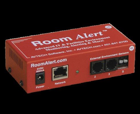
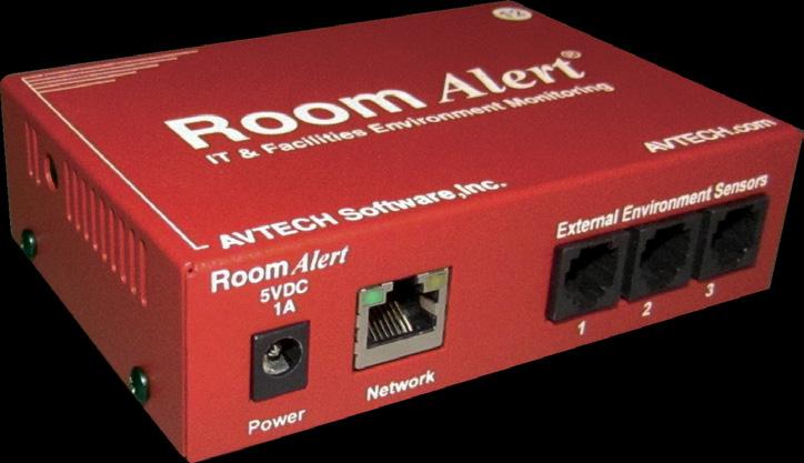
4 Room Alert Hardware Options Room Alert 3E Front Back 1 Power Port 2 Ethernet Port 3 Reset Button 4 Switch Sensor Port 5 Digital Sensor Port Internal Sensors Temperature Room Alert 4E Front Back Power Port Ethernet Port Digital Sensor Ports (2) Switch Sensor Port Reset Button Custom Light Tower Or Relay Port Internal Sensors Temperature Room Alert 12E Front Back Power Port Ethernet Port Internal Sensors Temperature Digital Sensor Ports (3) Reset Button Analog Input Port Light Tower & Relay Adapter Port Relay Output Port Switch Sensor Ports (4) 2 Room Alert User s Guide
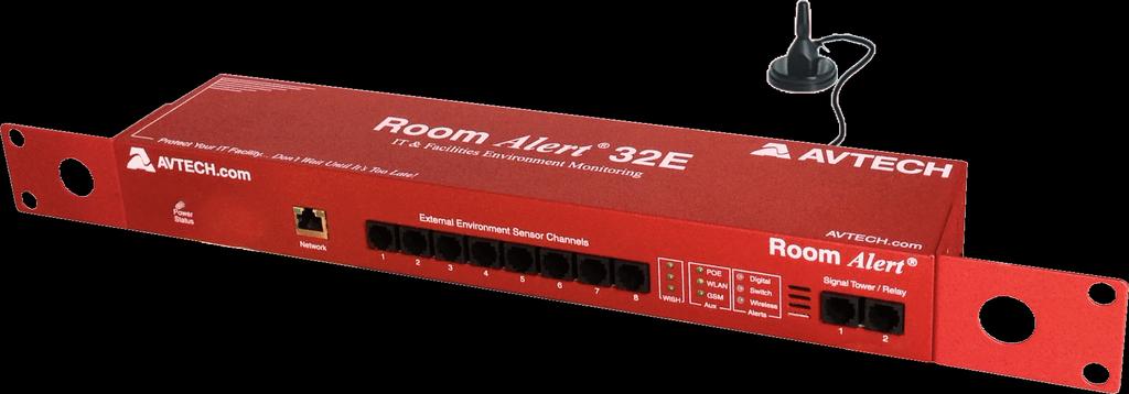
5 Room Alert 32E/W WiSH Signal Strength LEDs (RA32W only) 11 Front Power Status LED Ethernet Port Wireless Coaxial Port (RA32W only) Digital Sensor Ports (8) PoE, WLAN & GSM LEDs Alarm LEDs Light Tower & Relay Adapter Ports (2) Back Relay Output Ports (2) Analog Input Ports (2) Switch Sensor Ports (16) Internal Sensors Reset Button Power Port Battery Back-up On / Off Button Temperature Humidity Power Battery Back-up Room Alert User s Guide 3
6 Room Alert Hardware Features Internal Temperature Sensor An internal digital sensor monitors ambient temperature with a range of -40 to 185 F (-40 to 85 C). Internal Humidity Sensor Room Alert 32E/W An internal digital sensor monitors relative humidity with a range of 5% to 95% RH. Internal Power Sensor Room Alert 32E/W An internal sensor monitors the power state (main power or battery-back up power). 1 2 Internal Battery Back-up Room Alert 32E/W Power Port Ethernet Port PoE enabled on 32E/W, 12E & 3E An internal battery back-up can power Room Alert 32E/W for up to 15 minutes. A standard power port connects Room Alert to an electrical outlet with any AVTECH 5V 1A Power Adapter. Models are available for all countries. An RJ-45 port connects Room Alert to your network via an RJ-45 Ethernet cable Reset Button Switch Sensor Port(s) Digital Port(s) Custom Light Tower Or Relay Port Room Alert 4E Light Tower & Relay Adapter Port(s) Room Alert 32E/W, 12E & 3E Analog Input Port(s) Room Alert 32E/W & 12E Relay Output Port(s) Room Alert 32E/W & 12E A small push button resets Room Alert to factory default settings. (Please push softly.) Dry contacts connect Room Alert to any AVTECH switch sensor or dry contact on a device (e.g., HVAC, generator, pump, fan, etc.) via standard speaker wire or low-voltage 2-wire cable. Standard RJ-11 jack(s) connect any AVTECH digital sensor to Room Alert via a standard RJ-11 (straight through) telephone cord. The custom port allows you to directly connect a light tower or Relay Switch Sensor to Room Alert 4E. A standard RJ-11 jack connects a Light Tower & Relay Adapter to Room Alert 32E/W, 12E or 3E via a standard RJ-11 (straight through) telephone cord. Set(s) of contacts connect any low-voltage analog sensor to your Room Alert 32E/W or 12E via standard speaker wire. Set(s) of contacts connect any low-voltage device to your Room Alert 32E/W or 12E via standard speaker wire Power Status LED Room Alert 32E/W WiSH Signal Strength LEDs Room Alert 32W An LED indicates the power status of Room Alert 32E/W: Green = Main or PoE, Red = Internal UPS power. Three (3) LEDs indicate the signal strength of the last WiSH or WiSPR sensor to communicate with your Room Alert 32W: 3 = Strong, 1 = Weak signal. 4 Room Alert User s Guide
7 PoE, WLAN & GSM LEDs Room Alert 32E/W Alarm LEDs Room Alert 32E/W Antenna Port Room Alert 32W On / Off Button Room Alert 32E/W Three (3) LEDs indicate in use status of: Built-in PoE WLAN (possible future use) GSM (possible future use) Three (3) LEDs light red or green to indicate alarm or clear status of Digital, Switch or WiSH ( Room Alert 32W) sensors: Green = Clear, Red = Alarm. An RPSMA jack connects your Room Alert 32W to the included wireless antenna via the antenna s built-in coaxial cable. A push button turns the Room Alert 32E/W s internal battery back-up on and off. Standard Room Alert Packages Room Alert 3E The standard package includes: One (1) Room Alert 3E ID Box One (1) AVTECH 5V 1A Power Adapter One (1) Ethernet Cable (10') Room Alert 4E The standard package includes: One (1) Room Alert 4E ID Box (Rack Mount Bracket Optional) One (1) External Digital Temperature Sensor One (1) AVTECH 5V 1A Power Adapter One (1) Ethernet Cable (10') Room Alert 12E The standard package includes: One (1) Room Alert 12E ID Box One (1) External Digital Temperature Sensor One (1) External Power Sensor One (1) AVTECH 5V 1A Power Adapter One (1) Ethernet Cable (10') Room Alert 32E The standard package includes: One (1) Room Alert 32E ID Box One (1) External Digital Temperature Sensor One (1) External Room Entry Switch Sensor One (1) AVTECH 5V 1A Power Adapter One (1) Ethernet Cable (10') Room Alert 32W The standard package includes: One (1) Room Alert 32E ID Box One (1) External Digital Temperature Sensor One (1) External Room Entry Switch Sensor One (1) Internal Wireless Assembly & Antenna Port One (1) External Antenna w/13' Cable & Magnetic Mount One (1) External Wireless Sensor Hub (WiSH) One (1) AVTECH 5V 1A Power Adapter One (1) Ethernet Cable (10') Room Alert User s Guide 5

8 How To Install Your Room Alert Connect Your Room Alert Hardware If Your Network Is Power Over Ethernet (PoE) Enabled ( Room Alert 32E/W, 12E & 3E) Connect one end of a standard Ethernet cable to the Room Alert s Ethernet port. Connect the other end to a PoE-enabled network jack. That s it! Your Room Alert is now powered and discoverable on your network. If Your Network Is Not Power Over Ethernet (PoE) Enabled A. Connect To Your Network First Connect one end of a standard Ethernet cable to the Room Alert Ethernet port. Connect the other end to a network jack. A B. Then Connect To A Power Source Plug one end of AVTECH s 5V 1A Power Adapter into the Room Alert power port. Plug the other end into a surge-protected power source. B Your Room Alert is now powered and discoverable on your network! NOTE Use only AVTECH s 5V 1A Power Adapter. Other voltages could damage the Room Alert hardware and void your warranty. If you don t have an AVTECH 5V 1A Power Adapter, please visit our online store at AVTECH.com to acquire one. Models are available for all countries. Connect Included External Sensors And Other Compatible Components Please install included external sensors and any other compatible components you may have purchased according to their Installation Notes, available at AVTECH.com. 6 Room Alert User s Guide
9 How To Use Room Alert s Web Interface You may configure your Room Alert through its built-in web interface. To access the interface, you may either: Type the IP address of your Room Alert monitor directly into the address bar of your web browser. Select your Room Alert in the Device Discovery utility and click the Web button. Select your Room Alert in Device ManageR and click the Open Web button. Select your Room Alert in GoToMyDevices and click the Device Interface button. Your Room Alert s web interface has 3 tabs: Status Status Settings Help To view your Room Alert s current sensor status, select Status in the navigation bar to the left of your screen. Room Alert User s Guide 7
10 Banner & Header Banner At the top of the page runs the red Room Alert banner. Header You may collapse and expand the navigation bar on the left side of the page by selecting the menu icon in the banner. You may visit AVTECH.com by selecting the AVTECH logo in the banner. Below the banner is the header, where you may view basic information about your device. On the left side of the header, you may find the following information: Device Name Model MAC Address Serial Number Firmware Version Local IP Address Power Status ( Room Alert 32E/W) On the right side of the header, you may find the following information about the Room Alert s push status to GoToMyDevices: Push to GoToMyDevices is enabled (or disabled). The Room Alert is connected (or disconnected) from GoToMyDevices. 8 Room Alert User s Guide
11 The time & date the Room Alert last pushed sensor data to GoToMyDevices. You may click the GoToMyDevices logo to view the latest device information in your GoToMyDevices account. Sensor Display Area In the main viewing pane of the Status tab is the sensor display area. Here you may view your sensor data and temporarily change Status page settings. Temporary Status Page Settings You may temporarily change the refresh interval of the Status page and default temperature scale here. To temporarily modify the refresh interval of the Status screen, which is 60 seconds by default, you may enter a value in seconds in the Update Every field. Click outside the field to temporarily commit the change. To temporarily toggle the temperature scale between Fahrenheit (F) and Celsius (C), select Fahrenheit or Celsius. NOTE Refer to the Advanced section in this manual for instructions on setting the default status page refresh rate and temperature scale for Room Alert. Room Alert User s Guide 9
12 Alarm Status Icons Status icons are displayed for sensors that have thresholds set: Green circle with mark... Sensor is in a clear state. Red circle with X mark... Sensor is in an alarm state. No status icon... Sensor has no thresholds set. High And Low Reading Icons Arrows are displayed next to the highest and lowest readings on a sensor since the Room Alert last rebooted: Red upward arrow... Highest reading since last reboot of Room Alert. Blue downward arrow... Lowest reading since last reboot of Room Alert. Navigating The Status Page Your Room Alert displays your sensors in the following order: Digital Sensors Switch Sensors Wireless Sensors ( Room Alert 32E/W) Light Towers and Relays Built-in Analog Sensors ( Room Alert 32E/W & 12E) To navigate to the different types of sensors in the Sensor Display Area, you may scroll down the page or select the sensor category from the navigation bar to the left of your screen. NOTE Sensors connected to analog input ports and light tower & relay ports do not appear on the Status page until you enable them in the Settings screen. Refer to Settings in this manual for instructions. 10 Room Alert User s Guide
13 Settings Accessing Settings To access your Room Alert s settings: 1. First select Settings in the navigation bar to the left of your screen. 2. Then select the Click Here To Access Settings button in the window that appears. 3. Your browser will prompt you for a username and password. If you ve set up a password for your Room Alert, enter it and select OK. Otherwise, simply select OK without entering anything. Navigating Settings Settings has the following sub-tabs shown in the navigation bar to the left of your screen. Sensors Alarms Network SMTP SNMP Security Pings ( Room Alert 4E) Advanced You may navigate to each of these sections by selecting the appropriate sub-tab. Settings opens by default to the Sensor Settings page. Room Alert User s Guide 11
14 Saving Settings To save a setting, click out of the field you just modified and notice that a notification bar appears at the top and bottom of the page. This notification bar contains the following items: A list of Settings pages you have unsaved changes on. A Save Settings button. A Clear Changes button. You may navigate among the Settings pages, making changes in different places, and then save the changes all at once. When you are ready to save all the modifications you ve made, select the Save Settings button. Your Room Alert will automatically reboot and commit your changes. Before you save, if you decide you don t want the changes you just entered, you may re-load the page(s) without them by using the Clear Changes button. First select Clear Changes, and then select OK in the confirmation dialog box. Settings will re-load without your modifications. The Room Alert does not reboot, and any already-saved settings remain. 12 Room Alert User s Guide

15 Sensors Navigate to Settings Sensors to open the Sensor Settings screen. You may configure alert thresholds for your Room Alert s sensors in this screen. Your Room Alert sends alerts based on these thresholds. NOTE For more information about AVTECH sensors and accessories, please visit the Sensors and Accessories sections of AVTECH.com. NOTE Notice the Use Alarm Profile drop-down menu next to each sensor. If you have an AVTECH Light Tower, Relay Switch Sensor or built-in relays on your Room Alert, you may configure Alarm Profiles to toggle them on and off when alarms are detected. Please refer to the Alarms section in this manual for further information. Room Alert User s Guide 13
16 General Alarm Configuration Degrees Within Threshold Before Alarm Is Cleared ( Room Alert 32E/W) You may use this feature, available in the Room Alert 32E/W, to adjust how close your digital temperature sensor readings must get to a high or low threshold before their alarms clear. For example, with the default setting here of 1º and a high threshold of 80º, your temperature sensor will alarm when the temperature rises above 80º and clear when it falls below 79º; likewise, with a low threshold of 60º, the sensor will alarm when the temperature falls below 60º and clear when it rises above 61º. 1. In Degrees Within Threshold Before Alarm Is Cleared, you may leave the default, 1, or enter a value between 0.1 and Select Save Settings at the top or bottom of the page. Your Room Alert will automatically reboot and commit your changes. Trigger Alarm If Sensor Is Disconnected? You may configure your Room Alert to send an alert if any of the external digital sensors are disconnected from the unit. 1. Check Trigger Alarm If Sensor Is Disconnected? if you want to receive an alert if an external digital sensor becomes disconnected. This check box is blank by default. 2. Select Save Settings at the top or bottom of the page. Your Room Alert will automatically reboot and commit your changes. 14 Room Alert User s Guide
17 Alarm Thresholds (Internal and External Digital Sensor Alarm Configuration) You may configure alarm thresholds for the digital sensors both internal and external in this section. Room Alert model 32E/W has an internal Temperature & Humidity Sensor. Room Alert models 12E, 4E and 3E have an internal Temperature Sensor. In the example below, we will configure a Digital Temperature Sensor: 1. In Sensor Label, you may leave the default label, Internal Sensor (or Ext. Sensor 1, etc.) or rename it to something more descriptive, such as Server Rm Temp. TIP Room Alert sensor labels may be up to 15 characters and can include the following: letters, numbers, spaces, hyphens (-), underscores (_) and periods (.). 2. The Alarm On field automatically fills in, in this case with Temperature (F). NOTE Refer to the Advanced section in this manual for instructions on setting the default temperature scale. 3. In High and Low, you may leave the default, 0, or enter values for high and low temperature thresholds. Your Room Alert will generate alerts based on these thresholds. 4. In Adjust, you may enter a value to adjust the temperature reading if it differs from a known value at that location. 5. In Use Alarm Profile, which controls light towers and relays on your Room Alert, you may leave the default, Profile 1, or choose another profile from the drop-down menu. NOTE If you have an AVTECH Light Tower, Relay Switch Sensor or built-in relays on your Room Alert, you may configure Alarm Profiles to toggle them on and off when alarms are detected. Please refer to the Alarms section in this manual for further information. Room Alert User s Guide 15
18 6. Select Save Settings at the top or bottom of the page. Your Room Alert will automatically reboot and commit your changes. TIP The options in the Sensor Alarm Configuration fields vary slightly depending on the type of digital sensor. Analog Sensor Settings ( Room Alert 32E/W & 12E) If your Room Alert model has built-in analog input ports, you may configure the 0-5 VDC analog sensor connected to them in these fields. In the example below, we are configuring AVTECH s Current Loop First, enable the sensor by selecting Enabled in the set of fields on the left of the screen. The built-in analog sensor will not appear in the Room Alert web interface, Device ManageR, GoToMyDevices or SNMP program unless it is enabled. 2. In the set of fields on the right of the screen, select Enable to turn on the Reference, Scale and Units fields. In Reference, enter values from 5 to 0 that represent the High and Low points of your analog sensor s output signal range. In the case of the Current Loop 1, which outputs a signal of 0-5 VDC, we ve left the default values. In Scale, enter the High and Low points of the scale you want the Reference reading to be converted to. In our Current Loop example, we would like to convert 0-5 volts to 0-10 amps, so we ve replaced the default of 5 in High with 10 and left the default of 0 in Low. In Units, enter a 1 to 3-character label for the unit type that your readings will be measured in. If you are measuring amperage, as with the Current Loop, you might enter A or Amp, for example. Note that this field is merely a label and does not affect any of the calculations. 3. Return to the left side of the screen to enter your sensor label and thresholds: In Sensor Label, you may leave the default, Analog Sensor 1 or choose something 16 Room Alert User s Guide
19 more descriptive, such as Current Loop 1 or Cryogenic Temp. TIP Room Alert sensor labels may be up to 15 characters and can include the following: letters, numbers, spaces, hyphens (-), underscores (_) and periods (.). In High and Low, you may leave the default, 0 which means no alarm is configured or enter values that fall within the Scale range from the previous step. In our example, we entered a conversion scale of 0 to 10 (amps) in the previous step for the Current Loop, and we ve chosen to generate alarms at the high and low thresholds of 6 and 2 (amps). TIP With the custom scale enabled, you may enter positive and negative whole numbers in High and Low that fall within the Scale range; with the custom scale disabled, you may enter decimal numbers in the range of +/-5.0 (for 0-5 VDC). In Adjust, you may enter a value to adjust the reading if it differs from a known value. TIP With the custom scale enabled, you may enter decimal numbers in Adjust in the range of +/-12.0; with the custom scale disabled, you may enter decimal numbers in the range of +/ In Use Alarm Profile, which controls light towers and relays on your Room Alert, you may leave the default, Profile 1, or choose another Alarm Profile from the drop-down menu. NOTE If you have an AVTECH Light Tower, Relay Switch Sensor or built-in relays on your Room Alert, you may configure Alarm Profiles to toggle them on and off when alarms are detected. Please refer to the Alarms section in this manual for further information. 5. Select Save Settings at the top or bottom of the page. Your Room Alert will automatically reboot and commit your changes. Room Alert User s Guide 17
20 External Switch Sensor Settings You may configure the alert state for the external switch sensors in the Switch Sensor Settings fields. Shown below are the default settings. Your Room Alert monitors your switch sensors for an Open or Closed circuit state. Room Alert defaults to alarming on Closed, as you can see above; you may, however, need to change that depending on your sensor. AVTECH s Motion Sensor, for example, is Open when it detects movement and Closed when it doesn t; in that case, you d likely want to configure the sensor to alarm on Open or when motion is detected. The Alarm And Clear State Of Your Switch Sensor To determine the alarm and clear state of your sensor, you may either refer to its Installation Note or see for yourself by physically connecting your sensor to your Room Alert and then observing what happens to its circuit state in the Status page. After you connect your sensor and before you configure it in the Settings page, follow these steps: 1. Select the Status tab in the navigation bar to the left of your screen. 2. Scroll down to the Switch Sensors and look at the circuit state of the channel you connected your sensor to. If you connected your sensor to the first switch sensor port on Room Alert, look at Channel 1; if you connected it to the second, look at Channel 2, etc. 3. Notice the circuit state of Switch 1. It should show the normal state, which in this case is Closed. (Ignore the red color coding for now. We haven t configured the sensor yet, so it s still set at the default: alarm on closed.) 4. Now put the sensor into an alarm state. To put a Motion Sensor into an alarm state, for example, wave your hand in front of it. 5. Look at the circuit state at the same time. You should see it switch to the opposite of normal. In this example, if normal is Closed, you see the alarm state as Open. (Again, ignore the green color coding for now.) 18 Room Alert User s Guide
21 Now that you ve checked what Open and Closed mean on your switch sensor, navigate to Settings Sensors to configure your options in Switch Sensor Settings: 1. In Sensor Label, you may leave the default, Switch 1 (2, 3 or 4) or enter something more descriptive, such as Ext Motion or Main Entry. TIP Room Alert sensor labels may be up to 15 characters and can include the following: letters, numbers, spaces, hyphens (-), underscores (_) and periods (.). 2. In Alarm On, select the alarm state (Open or Closed). In our example, the alarm state is Open. 3. In Alarm Profile, which controls light towers and relays on your Room Alert, you may leave the default, Profile 1, or choose another Alarm Profile from the drop-down menu. NOTE If you have an AVTECH Light Tower, Relay Switch Sensor or built-in relays on your Room Alert, you may configure Alarm Profiles to toggle them on and off when alarms are detected. Please refer to the Alarms section in this manual for further information. 4. Select Save Settings at the top or bottom of the page. Your Room Alert will automatically reboot and commit your changes. TIP For any of the switch sensor sets you leave unused on your Room Alert, choose Disabled from the Alarm On drop-down menu to avoid confusion or false alerts. Room Alert User s Guide 19
22 Internal Power Sensor Alarm Configuration ( Room Alert 32E/W & 12E) You may configure the power sensor that is built in to the Room Alert 32E/W here. This internal power sensor triggers on loss of main power and can send a notification while the battery backup keeps the Room Alert monitor powered for a short time. 1. In Sensor Label, you may leave the default Power Sensor or enter something more descriptive, such as RA32 Power. TIP Room Alert sensor labels may be up to 15 characters and can include the following: letters, numbers, spaces, hyphens (-), underscores (_) and periods (.). 2. In Alarm On Power Loss, you may leave the checkbox filled in if you wish to receive an alert when your Room Alert 32E/W loses its main power source. Otherwise, you may uncheck it. 3. In Alarm Profile, which controls light towers and relays on your Room Alert, you may leave the default, Profile 1, or choose another Alarm Profile from the drop-down menu. NOTE If you have an AVTECH Light Tower, Relay Switch Sensor or built-in relays on your Room Alert, you may configure Alarm Profiles to toggle them on and off when alarms are detected. Please refer to the Alarms section in this manual for further information. 4. Select Save Settings at the top or bottom of the page. Your Room Alert will automatically reboot and commit your changes. 20 Room Alert User s Guide
23 WiSH Sensors ( Room Alert 32W) Your Room Alert 32W web interface automatically detects Wireless Sensor Hubs (WiSHs) and Wireless Sensor Hub & Powered Relays (WiSPRs) that are in range. Below you see the WiSH Sensor Settings screen detecting a WiSH or WiSPR sensor. 1. In WiSH Sensor, choose the discovered WiSH you want to configure from the drop-down list. In this example, we ve chosen WiSH Sensor In Sensor Label, you may leave the default, WiSH Sensor 1, or enter something more descriptive, such as Server Rm WiSH. Room Alert User s Guide 21
24 TIP Room Alert sensor labels may be up to 15 characters and can include the following: letters, numbers, spaces, hyphens (-), underscores (_) and periods (.). 3. In Serial #, the interface automatically detects and displays the WiSH sensor s serial number. In this example, WiSH Sensor 1 s serial number is Record this number on the sticker on the bottom of your WiSH sensor so you ll know which physical WiSH corresponds to what you re seeing in the interface. AVTECH WiSH (Power) Sensor works with Room Alert 32W and 26W only. Do NOT leave powered when not in use. Serial # vx.x AVTECH.com * TIP Room Alert 32W can support up to 10 WiSH or WiSPR hubs at one time. This adds a capacity of 40 additional sensors. Visit the Sensors section of AVTECH.com to purchase additional WiSH or WiSPR hubs and sensors. 5. Only click Reset This WiSH Sensor if you wish to clear your current WiSH settings and change them back to the defaults. 6. In the WiSH s Sensor Alarm Configuration sections, you may enter labels and thresholds for your WiSH s internal and external digital sensors and external switch sensor. Configuring internal and external digital sensors and external switch sensors has been covered in this manual in the Sensors section; please refer back to that section for instructions on configuring sensors connected to the WiSH, or look specifically at the subsections listed below: WiSH Internal and External Digital Sensor Alarm Configuration Please refer to Alarm Thresholds (Internal and External Digital Sensor Alarm Configuration) in this manual for instructions on configuring the WiSH s internal temperature sensor and any external digital sensors you may connect in the WiSH s 2 digital sensor ports. WiSH Switch Sensor Alarm Configuration Please refer to External Switch Sensor Settings in this manual for instructions on configuring the external switch sensors you connect to the WiSH. 7. In Use Alarm Profile, which controls light towers and relays on your Room Alert, you may leave the default, Profile 1, or choose another Alarm Profile from the drop-down menu. 22 Room Alert User s Guide
25 The Profile you choose here applies to all sensors connected to the WiSH being configured: its internal, external digital and external switch sensors. NOTE If you have an AVTECH Light Tower, Relay Switch Sensor or built-in relays on your Room Alert, you may configure Alarm Profiles to toggle them on and off when alarms are detected. Please refer to the Alarms section in this manual for further information. 8. Select Save Settings at the top or bottom of the page. Your Room Alert will automatically reboot and commit your changes. Repeat the steps above for each discovered WiSH. A maximum of ten WiSH or WiSPR hubs can be used with each Room Alert 32W monitor. NOTE Please also see the Advanced section in this manual for the WiSH Options tab, which provides more configuration options for WiSH and WiSPR sensors. Room Alert User s Guide 23

26 Alarms Navigate to Settings Alarms to open the Alarm Settings screen. Here you may configure light towers and relays. Light Tower/Relay Profile Configuration In this example, we ll select and name a Light Tower w/audio in LTA 1 and then configure its Profile In LTA 1 Label, you may leave the default, Light Tower 1 or enter something more descriptive, such as Server Rm RYG. 24 Room Alert User s Guide


27 2. In LTA 1 Connected, select the appropriate option from the choices in the drop-down menu. For this example, we are choosing Red/Yellow/Green w/audio for the Light Tower w/audio. 3. Once you choose your device, the Alarm Profile configuration grid beneath it expands. Notice that all features are set to Off by default. TIP The features available vary depending on the device you ve selected. 4. Choose the Profile you wish to configure in the Profile drop-down list. Depending on your model, you may have 1 to 5 available Profiles, plus a Boot Profile where you can configure what the light tower or relay features do when the device first boots. All models have the Boot Profile. Room Alert model 32E/W offers 5 additional profiles (Profiles 1-5). Room Alert model 12E offers 3 additional profiles (Profile 1-3). Room Alert models 4E and 3E offer 1 additional profile (Profile 1). Light Tower & Relay Adapter (LTA) A Light Tower & Relay Adapter gives you the option to add an AVTECH Light Tower, Light Tower w/audio or Relay Switch Sensor to a Room Alert 32E/W, 12E or 3E. (The Room Alert 4E does not require a Light Tower & Relay Adapter, allowing for a direct connection.) You may also connect a low-voltage device directly to the built-in relay port on the Light Tower & Relay Adapter. Shown here is a sample configuration: Room Alert 32E/W, 12E or 3E + RJ-11 Cable + Light Tower & Relay Adapter + Light Tower Custom Cord + Light Tower w/audio NOTE The Light Tower w/audio in this configuration can be replaced with a standard Light Tower or Relay Switch Sensor. For more information about AVTECH sensors and accessories, please visit the Sensors & Accessories sections of AVTECH.com. Room Alert User s Guide 25
28 Relay Action Configuration ( Room Alert 32W & 12E) Here you may set the devices connected through the built-in relay output port(s) to turn on or off in response to your Room Alert 32E/W or 12E rebooting or its sensors going in and out of alarm state. In this example, we ll configure Relay In Sensor Label, you may leave the default, Relay Output 1, or enter something more descriptive, such as Server Rm AC. TIP Room Alert sensor labels may be up to 15 characters and can include the following: letters, numbers, spaces, hyphens (-), underscores (_) and periods (.). 2. Choose the Profile you wish to configure in the Profile drop-down list. Depending on your model, you may have 3 to 5 available Profiles, plus a Boot profile where you can configure what the built-in Relay does when the Room Alert monitor boots on. Room Alert model 32E/W offers the Boot profile plus 5 additional profiles. Room Alert model 12E offers the Boot profile plus 3 additional profiles. Associate Alarm Profiles With Sensors Each sensor is set at Profile 1 by default; connected light towers, built-in LTA relays, Relay Switch Sensors and built-in relay outputs execute Profile 1 when that sensor goes into an alarm state. You may associate a profile with a sensor by following the steps below. In this example from a Room Alert 32E, you can see we have 5 profiles to choose from: 1. Navigate to Settings Sensors. 2. Find your sensor s interface and choose the profile you ve configured from the drop-down 26 Room Alert User s Guide
29 list in Use Alarm Profile. Note that the default for all sensors is Profile 1. You may also choose No Alarm if you do not want to associate your sensor with a profile. 3. Select Save Settings at the top or bottom of the page. Your Room Alert will automatically reboot and commit your changes. TIP Alarm Profiles affect only light towers and relays; they do not affect alerts. Room Alert User s Guide 27

. 2. Select Save Settings at the top or bottom of the page. Your Room Alert will automatically reboot and commit your changes.")
30 Network Navigate to Settings Network to open the Network Settings screen. Device Name To rename your Room Alert: 1. Select the automatically-assigned name in Device Name and enter a new one of up to 15 alphanumeric characters. TIP Room Alert device names may be up to 15 characters and can include the following: letters, numbers, spaces, hyphens (-), underscores (_) and periods (.). 2. Select Save Settings at the top or bottom of the page. Your Room Alert will automatically reboot and commit your changes. IP Address Configuration DHCP 28 Room Alert User s Guide
31 To obtain an IP address automatically using DHCP: 1. Select Obtain IP Address Automatically. 2. Typically, leave the BOOTP, DHCP and AutoIP checked (enabled), which is the default. 3. Select Save Settings at the top or bottom of the page. Your Room Alert will automatically reboot and commit your changes. IP Address Configuration Static IP To assign a static IP address: 1. Select Use The Following IP Configuration. 2. In IP Address, enter the new static IP address. 3. In Subnet Mask, enter the subnet mask. 4. In Default Gateway, enter the gateway IP address. 5. In DNS Server IP, enter the DNS server IP address. 6. Select Save Settings at the top or bottom of the page. Your Room Alert will automatically reboot and commit your changes. TIP Make sure that you do not use an IP address that is already assigned to another device. Also, set the IP address within your current subnet range; otherwise, you may not be able to discover your Room Alert. Room Alert User s Guide 29
32 Ethernet Configuration Typically, you may leave the Ethernet Configuration section at the defaults, which are shown below. However, if you connect your Room Alert to a managed switch that controls your network traffic, you may need to change these settings: 1. In MTU Size, you may leave the default, 1024, or enter a value as low as You may uncheck Auto Negotiate and choose: For Speed, 100 Mpbs or 10 Mbps. For Duplex, Full or Half. 3. You may uncheck Gratuitous ARP Broadcasts to disable them. 4. Select Save Settings at the top or bottom of the page. Your Room Alert will automatically reboot and commit your changes. 30 Room Alert User s Guide

33 SMTP You may configure your Room Alert to send alerts via and -to-sms. Navigate to Settings SMTP to open the Settings screen. 1. Check Enabled. 2. You may leave Footer Enabled checked to include AVTECH contact information with messages. 3. You may check Use SMS to send a shorter with a reduced character count. 4. Mail Server: In Domain Name/IP, enter the domain name or IP address of your mail server. In Port, enter your mail server s SMTP port. The default is 25, a commonly-used port. Room Alert User s Guide 31
34 In Timeout, you may leave the default, 5 seconds, or enter another interval. 5. In Return Address (From), enter an address that resides on your mail server. This is the address alert messages will come from. 6. In Recipients, enter the and -to-sms addresses that you d like to send alerts to. Separate each address with a comma. (Do not enter spaces after the commas.) address: ITMgr@Example.com -to-SMS address: @ATT.txt.net Addresses separated by commas: ITMgr@Example.com, @ATT.txt.net, etc. 7. Display URL controls what IP or URL displays in alerts. You may leave the default, a disabled, blank field, or enter a custom IP address or URL. To make a custom entry, you must first check Display URL Enabled. When this field is left at the default (disabled, blank), your alerts will contain the Room Alert s current IP address and HTTP port number in the body of the . When this field is overwritten with a custom IP or URL, your alerts will contain that custom IP or URL in the body of the . Authentication (Optional) 8. If your mail server requires SMTP authentication, check Enable Authentication. 9. In Username and Password, enter a valid username and password for your mail server that will facilitate authentication. TIP Your password cannot be more than 11 alphanumeric characters. 10. Select Save Settings at the top or bottom of the page. Your Room Alert will automatically reboot and commit your changes. When your Room Alert reboots, return to the Settings screen and select Send Test to send a test to the addresses you entered in Recipients. 32 Room Alert User s Guide

35 Simple Network Management Protocol (SNMP) Because your Room Alert is fully SNMP-compliant, you have the option to monitor it with a 3 rd -party monitoring application capable of performing SNMP queries. You may configure Room Alert to send SNMP Traps in response to a change in alarm states to up to three host systems running 3 rd -party SNMP monitoring applications. If you use a 3 rd -party SNMP monitoring application: Obtain the Room Alert MIB files and load them into your SNMP monitoring application. Otherwise, your application cannot properly translate the data it receives in the SNMP Trap. NOTE You may download the MIB files through your active customer subscription at GoToMyDevices.com or from the SNMP Settings page in your Room Alert s web interface. Ensure that your application uses SNMPv1. Note that your Room Alert communicates with your SNMP monitoring application using the standard port for the SNMP protocol, 161. Navigate to Settings SNMP to open the SNMP Settings screen. Room Alert User s Guide 33
36 SNMP Configuration To begin configuring your Room Alert for SNMP: 1. In Community Name, you may leave the default SNMP protocol community name, public, or enter a new name. TIP The community name you assign here must match the one in your 3 rd -party SNMP monitoring application. 2. You may leave Contact (syscontact) blank or enter a person s name to specify who is receiving the information. 3. You may leave Location (syslocation) blank or enter the location of your Room Alert monitor. 4. You may select Use 2 digit SNMP if you prefer to receive values in 2-digit rather than 4-digit format. TIP Room Alert sends values to your 3 rd -party SNMP monitoring application in 4-digit format by default F, for example, appears as In 2-digit format, your values are truncated, not rounded to the nearest number. In this example, would appear as Select Save Settings at the top or bottom of the page. Your Room Alert will automatically reboot and commit your changes. SNMP Trap Sending Configuration You may configure your Room Alert to send SNMP Traps in response to a change in alarm state to up to three host systems running 3 rd -party SNMP monitoring applications. Each host system you enter in these fields will receive the same SNMP Traps simultaneously. 34 Room Alert User s Guide
37 To configure your Room Alert to send SNMP Traps: 1. In Trap Send IP 1, enter the IP address of the host system that runs your 3 rd -party SNMP monitoring application. 2. In Trap Send IP 2 and Trap Send IP 3, you may enter the IP addresses of other host systems that run 3 rd -party SNMP monitoring applications, or leave the default, Select Save Settings at the top or bottom of the page. Your Room Alert will automatically reboot and commit your changes. SNMP Trap Receiving Configuration ( Room Alert 4E) You may configure your Room Alert 4E to receive SNMP Traps from up to three other network devices, such as printers, fax machines, etc. When Room Alert 4E receives a trap message, it generates an alarm and can toggle a light tower or relay outputs. To configure your Room Alert 4E to receive SNMP Traps: 1. In Trap Receive IP 1, enter the IP address of the network device. 2. In Trap Receive IP 2 and Trap Receive IP 3, you may enter the IP addresses of other network devices, or leave the default, Select Save Settings at the top or bottom of the page. Your Room Alert will automatically reboot and commit your changes. If all of the Trap Receive IP addresses are left blank, any SNMP trap received will generate an alarm. Room Alert User s Guide 35

38 Security By default, Room Alert does not require log in credentials; you may, however, create a password for your Room Alert for extra security. Navigate to Settings Security to open the Security Settings screen. Password 1. In New Password, you may create a log in password of up to 15 alphanumeric characters for your Room Alert. TIP Use only letters and numbers in your log in password no special characters, please. 2. Re-enter the password in the Confirm Password field to verify. 3. Select Save Settings at the top or bottom of the page. Your Room Alert will automatically reboot and commit your changes. NOTE If you forget your password, you can reset your Room Alert settings to the factory defaults. Please see the How To Reset Room Alert To Factory Defaults section of this manual for more information. There is no other alternative. When you reset to defaults, you lose all of your previously configured settings, including password security. 36 Room Alert User s Guide
39 Username ( Room Alert 4E) In addition to a password, you may, if you wish, configure a username for your Room Alert 4E. 1. In New Username, you may create a username of up to 8 characters. 2. In New Password, you may create a log in password of up to 15 characters. TIP Use only letters and numbers in your log in username and password no special characters, please. 3. Re-enter the password in the Confirm Password field to verify. 4. Select Save Settings at the top or bottom of the page. Your Room Alert will automatically reboot and commit your changes. NOTE If you forget your username or password, you can reset your Room Alert settings to the factory defaults. Please see the How To Reset Room Alert To Factory Defaults section of this manual for more information. There is no other alternative. When you reset to defaults, you lose all of your previously configured settings, including username and password security. Room Alert User s Guide 37

40 Ping ( Room Alert 4E) You may configure up to eight IP addresses to ping from your Room Alert 4E in this screen. Room Alert will send a ping to those addresses to check if the host is reachable. If the host is up, the ping will return as successful and register a normal state; if the host is down, or Room Alert cannot reach it, the ping will return as failed and register an alarm state. Navigate to Settings Ping to open the Ping Settings screen. Ping Configuration 1. In Retry Count, you may enter the number connection attempts Room Alert will make before an alarm condition is generated. The default is In Timeout, you may enter the number of seconds to wait for a reply to the connection attempt. Ping Host Addresses 3. In the Ping Host Addresses table, you may enter up to 8 IP addresses. The default for each is Select Save Settings at the top or bottom of the page. Your Room Alert will automatically reboot and commit your changes. 38 Room Alert User s Guide
41 Advanced You may configure a number of advanced options here, including Status screen defaults, Device ManageR Push, time & date, trace output and WiSH sensor options. Navigate to Settings Advanced to open the Advanced Settings screen. The Advanced Settings screen has 4 to 5 sub-tabs, depending on your Room Alert model: General Device ManageR Configuration Date & Time Configuration Trace Configuration WiSH Sensor Options ( Room Alert 32W) Room Alert User s Guide 39

42 General Navigate to Settings Advanced General to open the General screen, where you may set defaults for the Status screen. 1. In Refresh Rate enter the number of seconds you would like the Status screen to refresh at. You may enter a value from 5 to The default is 60 seconds. 2. In HTTP Port, you may change the port number your web browser uses to connect to your Room Alert s web interface. It uses port 80 by default. 3. In Temperature Scale, you may choose Fahrenheit or Celsius from the drop-down list. Fahrenheit is the default. 4. Select Save Settings at the top or bottom of the page. Your Room Alert will automatically reboot and commit your changes. 40 Room Alert User s Guide

43 Device ManageR Push Configuration Navigate to Settings Advanced Device ManageR Configuration to configure settings for the unit to push to Device ManageR. By default, Device ManageR queries your Room Alert for sensor values at defined intervals. However, you may configure your Room Alert to proactively send sensor updates to Device ManageR by enabling Device ManageR Push. Enabling Device ManageR Push is an advantage for two reasons: Your Room Alert can communicate with Device ManageR from a remote network without requiring complex firewall rules on the remote network. Firewalls typically allow outgoing connections while blocking incoming connections. Your Room Alert can immediately send an update to Device ManageR when it detects an alarm, regardless of any intervals you have configured either in this section or in the Device ManageR discovery interval. To enable Push to Device ManageR from your Room Alert: 1. Select Enable Push. 2. In Server IP Address, enter the IP address of Device ManageR s host system. 3. In Server Port, enter the port Device ManageR uses. The default is In Push Interval, choose the number of minutes you would like between pushes when no alarms are detected. 5. Select Save Settings at the top or bottom of the page. Your Room Alert will automatically reboot and commit your changes. Room Alert User s Guide 41
 is the default 2. In Time Display, you may select the 12 or 24 hour format from the drop-down list.")
44 Time & Date Configuration Navigate to Settings Advanced Date & Time Configuration to configure the time and date defaults for your Room Alert. 1. In Time Zone, select your time zone from the drop-down list. Greenwich Mean Time (GMT) is the default 2. In Time Display, you may select the 12 or 24 hour format from the drop-down list. The 24 hour setting is the default. 3. In Time Format, you may select either the MM/DD/YY or DD/MM/YY date format from the drop-down list. Month first (MM/DD/YY) is the default. 4. Select Enable Daylight Savings if you would like your Room Alert time setting to compensate by +1 hour for daylight savings time. Time Server 5. In IP, you may leave Room Alert s default Network Time Protocol (NTP) server, time.nist.gov, or enter another time server IP address. To use a different IP address, you must check Enable custom time server, located just above this field. 6. However, if you d rather enter your NTP hostname, select Resolve Host Name. 42 Room Alert User s Guide
45 When the DNS Resolver dialog box opens, enter the hostname of your time server and select Resolve. After the resolver successfully translates the hostname into an IP address, select Insert to put that IP address into the IP field of the Date & Time Configuration screen. 7. In Time Server Auto Refresh, you may select how often Room Alert automatically synchronizes with your time server. You may leave the default, 24 Hours, or choose another interval, as frequent as 10 minutes, from the drop-down list. You may also disable time synchronization by selecting Disabled from the drop-down list. You may manually synchronize the time by selecting Update Now. Clicking this button does not affect the Auto Refresh interval. 8. Select Save Settings at the top or bottom of the page. Your Room Alert will automatically reboot and commit your changes. Room Alert User s Guide 43

46 Trace Configuration Navigate to Settings Advanced Trace Configuration to configure your Room Alert for trace output, which is useful for troubleshooting. Trace output shows the communication between your Room Alert and your mail server, as well as other information, such as the current firmware version, IP address, MAC address, and requests to web pages. To configure trace output: 1. Select Enable. 2. In Port, you may leave the default port, 143, or enter another port number. 3. Select Save Settings at the top or bottom of the page. Your Room Alert will automatically reboot and commit your changes. You may then use any standard telnet or terminal application to view the trace on the configured port. 44 Room Alert User s Guide

47 WiSH Options ( Room Alert 32W) Navigate to Settings Advanced WiSH Options to access advanced options and filters for each Wireless Sensor Hub (WiSH) or Wireless Sensor Hub & Powered Relay (WiSPR). Advanced WiSH Sensor Options 1. In Enable WiSH Lost Communications Alarms, you may leave the box checked, which is the default, or disable it by unchecking the box. 2. In WiSH Timeout, you may enter the number of packets to allow Room Alert to miss before an alarm is generated. You may enter a value between 10 and 254; the default is 10. This prevents false alerts if the wireless signal is temporarily interrupted. 3. In WiSH Sensors Enabled, you may specify the maximum number of WiSH or WiSPR units you want to monitor. You may leave the default, 10, or enter a lower number. 4. Only click Reset All WiSH Sensors if you wish to clear settings for all of your WiSH sensors and change them back to defaults. WiSH Sensor Filter Configuration In this section, you may block your Room Alert 32W from communicating with some or all of your WiSH sensors. You may need this feature if you want only certain WiSHs recognized. 1. In Enable WiSH Sensor Filter, check the box to enable filtering. It is disabled (unchecked) by default. Room Alert User s Guide 45
48 2. In Allowed WiSH Sensors, you see a list of WiSHs recognized by your Room Alert 32W. To block a certain WiSH, perform these steps: Click on the WiSH to highlight it. Select Block to move that WiSH to the Blocked WiSH Sensors box. 3. Then select Save Settings at the top or bottom of the page. Your Room Alert will automatically reboot and commit your changes. To later unblock that WiSH: 1. In Blocked WiSH Sensors, you see a list of WiSHs that have been blocked. Click on the WiSH to highlight it. Select Allow to move that WiSH from the Blocked WiSH Sensors box back to the Allowed WiSH Sensors box. 2. Then select Save Settings at the top or bottom of the page. Your Room Alert will automatically reboot and commit your changes. 46 Room Alert User s Guide
49 Updating & Troubleshooting Your Room Alert How To Download Firmware & Software Updates From GoToMyDevices Software and firmware updates are available to customers with an active customer subscriptions to GoToMyDevices.com. To download: 1. Log in to GoToMyDevices.com. TIP If you ve forgotten your password, select the Forgot Password link on the log in page and follow the on-screen instructions. 2. Select Downloads in the navigation bar to the left of your screen to open the Downloads page. There you ll see the software, firmware and MIB products you are currently enabled for. The available options are based on the registered AVTECH products for your organization. 3. To download, click the Download button next to the appropriate product. How To Update Room Alert s Firmware 1. Download and save the most recent firmware update for Room Alert from your customer account at GoToMyDevices.com. 2. Open AVTECH s Device ManageR software or Device Discovery utility. (If you don t already have one of them installed, you may download it from your customer account.) 3. Select your Room Alert from the list of discovered devices. 4. In Device ManageR, select the Update Firmware link shown under the product name. Or, in Device Discovery, select the Update button at the top right of the screen. 5. Then follow the on-screen instructions to complete the update. TIP IMPORTANT: Be sure that there are no web browsers accessing your Room Alert monitor from anywhere on your network before uploading the firmware as this could cause the firmware update to be incomplete or become corrupted. How To Discover Room Alert When Your Network Blocks UDP Broadcasts If your network blocks UDP broadcast packets on port 30718, AVTECH s Device ManageR or Device Discovery might not be able to automatically locate the Room Alert monitor. To manually discover your Room Alert, use the Advanced Discovery option in AVTECH s Device ManageR Application: Room Alert User s Guide 47
50 1. Open AVTECH s Device ManageR software or Device Discovery utility. (If you don t already have one of them installed, you may download it from your customer account at GoToMyDevices.com.) 2. In Device ManageR, select the Advanced Discovery Options button under the Device Status tab in the navigation bar to the left of your screen; then, in the Advanced Discovery Options dialog box, select Manually Add Device(s) Via IP Address. Or, in Device Discovery, select the Advanced Discovery button at the top left of the screen. 3. Enter your Room Alert s IP address or the range of IP addresses assigned to DHCP devices on your network. 4. Select Begin Scan, which initiates a TCP scan on port in Device ManageR or a UDP unicast on port in Device Discovery. 5. When the scan is complete in Device ManageR, select Close Window and your Room Alert should be automatically added to the list of discovered devices. Or, once the scan is complete in Device Discovery, your Room Alert should be automatically added to the list of discovered devices. How To Reset Room Alert To Factory Defaults You may need to reset your Room Alert to factory defaults if: You are moving it to a new location and it must be reconfigured. It has been assigned invalid network settings and is therefore inaccessible. You have lost your Room Alert s password. If your Room Alert is accessible on the network, to reset it to factory defaults: 1. Navigate to Settings Advanced in the web interface. 2. Select Reset to Defaults in the upper right corner of the page. 3. Select Yes when the Confirm Reset dialog box appears. 4. Your Room Alert will automatically reboot and attempt to obtain an IP address via DHCP. 5. To automatically discover your Room Alert on your network, open AVTECH s Device 48 Room Alert User s Guide
51 ManageR software, Device Discovery utility or log in to your GoToMyDevices account. If your Room Alert is not accessible on the network, to reset it to factory defaults: 1. With your Room Alert connected to the network and powered on, press and hold the reset button for at least 10 seconds until the left LED over the network jack turns off and then on again. 2. Your Room Alert will automatically reboot and attempt to obtain an IP address via DHCP. 3. To automatically discover your Room Alert on your network, open AVTECH s Device ManageR software, Device Discovery utility or log in to your GoToMyDevices account. TIP IMPORTANT: When you reset to factory defaults, you lose all of your previously configured settings, including password security. Room Alert User s Guide 49


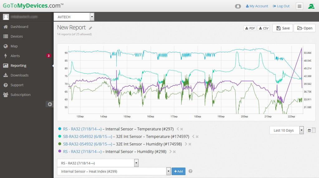
52 Introduction To AVTECH s GoToMyDevices Cloud Service Monitor unlimited Room Alert devices and sensors through the cloud with from anywhere anytime! It's quick, easy and powerful. Enjoy the same look and feel from any device, whether you use a phone, tablet, laptop or desktop computer. Alert, log, graph, view, report, and manage your Room Alerts, with no software for to install or update. Alerting Creating alerts in GoToMyDevices is quick and easy. Simply enter your or -to-sms address, choose your device and sensor, and set your thresholds. That s it! GoToMyDevices can send alerts to any or -to-sms address you choose with no mail server set up required! Reporting Eye-catching reports are a few clicks away just pick a device and a sensor to add it instantly to an easy-to-read graph. GoToMyDevices also has convenient features that allow you to manipulate your view of your graph: Compare individual sensors from different Room Alerts or locations side by side. Slide a common point across the graph to watch sensor values change across time or bold an individual line to emphasize it. Zoom in on the graph vertically or horizontally to get up close to your values; move your view up or down to get a better look. Compare sensors of different types easily with dual y-axis scales on your graph. Track temperature on the left and a switch sensor or relay on the right for a better picture of your environment. 50 Room Alert User s Guide


53 Color code your sensors to make them more readable using the intuitive color wheel. Download your data points to a CSV file to work with them in a spreadsheet application. Locations & Maps Use the mapping feature to see where you have devices installed and immediately know what locations have alerts in progress. Your devices are displayed below the map--simply click the location field for each device to enter a street address, zip code, coordinates, or any other location that can be displayed on a map. Push to GoToMyDevices.com Room Alert keeps you up-to-date by pushing sensor data to GoToMyDevices under the conditions listed below: On boot. On +/- 1º C change on internal and external temperature sensors. On +/- 1% change on internal or external humidity sensors. On +/-.25 V change on internal or external analog sensors. On an open/closed state change for switch sensors. Once an hour after the last push regardless of the state of your sensors. When any threshold configured on the unit itself is passed or cleared. Sign Up Create an account today at GoToMyDevices.com to begin! Room Alert User s Guide 51


54 Introduction To AVTECH s Device ManageR Manage Unlimited Room Alerts Control all of your Room Alert devices from a single web browser interface, accessible from anywhere. Take automatic corrective actions, run scripts and notify unlimited contacts on the device of their choice. Use dashboard widgets to customize your interface and display the information most important to you in real time. Automatically log and graph all of your sensor data for a comprehensive history of environmental conditions. Control the log file size automatically. Manage Unlimited Network Cameras View all of your Axis camera displays simultaneously and control who has access! Automatically Axis camera snapshots in response to alert conditions. Customize your alerts with links to your Axis cameras for oneclick access to real-time video. Expand Functionality With Plugins Send customized reports with advanced statistics according to a schedule or in response to alert conditions. Modify according to each user s needs. Log off, shut down, reboot and execute commands or scripts on Windows and Linux/Unix systems across your network. Automatically text or call contacts with alerts using a text, voice or GSM (satellite) modem. Download Device ManageR From Your GoToMyDevices Account Download AVTECH s Device ManageR software from your active customer subscription at GoToMyDevices.com. 52 Room Alert User s Guide
Room Alert. Room Alert 32E, 12E, 4E & 3E. Temperature & Environment Monitoring... Made Easy! User s Guide & Reference Manual
 Room Alert Temperature & Environment Monitoring... Made Easy! Room Alert 32E, 12E, 4E & 3E Phone 401.628.1600 Fax 401.628.1601 Web AVTECH.com User s Guide & Reference Manual AVT-171212-1.1.0 Contact Us
Protect Your Facility...
 Sensors Autumn 2016 Protect Your Facility... Don t Wait Until It s Too Late! TM Install Room Alert Monitors The Most Advanced, Easy-To-Use, Reliable & Affordable Monitors Available To... MONITOR, ALERT...
Protect Your Facility...
 Catalog Autumn 2016 Protect Your Facility... Don t Wait Until It s Too Late! TM Install Room Alert Monitors The Most Advanced, Easy-To-Use, Reliable & Affordable Monitors Available To... MONITOR, ALERT...
AVTECH. Digital Active Power Sensor. Installation Note
 AVTECH Digital Active Power Sensor AVTECH s Digital Active Power Sensor monitors active power status and ambient room temperatures. Simply strap the sensor to the AC electrical cord of any device that
Protect Your Facility...
 Catalog Autumn 2014 Protect Your Facility... Don t Wait Until It s Too Late! TM Install Room Alert Monitors The Most Advanced, Easy-To-Use, Reliable & Affordable Monitors Available To... MONITOR, ALERT...
IndigoVision Alarm Panel. User Guide
 IndigoVision Alarm Panel User Guide THIS MANUAL WAS CREATED ON 2/21/2017. DOCUMENT ID: IU-AP-MAN002-4 Legal considerations LAWS THAT CAN VARY FROM COUNTRY TO COUNTRY MAY PROHIBIT CAMERA SURVEILLANCE. PLEASE
Sound Light & Entry Sensor (RMA-SLE-SEN) Installation Note
 Installation Note") Installation Note AVTECH s Sound Light & Entry Sensor (SLE) effectively monitors unstaffed or low-traffic areas: while its built-in sensors detect the occurrence of sound and light in a room, its attached
Installation Note AVTECH s Sound Light & Entry Sensor (SLE) effectively monitors unstaffed or low-traffic areas: while its built-in sensors detect the occurrence of sound and light in a room, its attached
ICT180S-12I INTELLIGENT MODEL (SERIES 2)
") The Power of Reliability ICT180S-12I INTELLIGENT MODEL (SERIES 2) INSTRUCTION MANUAL TABLE OF CONTENTS Warnings Page 2 Product Description Page 3 Installation Page 4 LCD/Select Button Operation Page 7
The Power of Reliability ICT180S-12I INTELLIGENT MODEL (SERIES 2) INSTRUCTION MANUAL TABLE OF CONTENTS Warnings Page 2 Product Description Page 3 Installation Page 4 LCD/Select Button Operation Page 7
Avigilon Control Center 5 System Integration Guide
 Avigilon Control Center 5 System Integration Guide for Paxton Net2 Access Control Systems 2014 Avigilon Corporation. All rights reserved. Unless expressly granted in writing, no license is granted with
Alarm module for leak detection with webserver
 This instruction document consists of 2 parts : one part about the assembly of the components and one part about configuration and starting-up of the system. The assembly is done by the qualified installer
BROADBAND MODEL WITH REMOTE POWER CONTROL (SERIES 2) ICT180S-12BRC (FOR POSITIVE GROUND SYSTEMS) ICT180S-12BRCP (FOR NEGATIVE GROUND SYSTEMS)
 ICT180S-12BRC (FOR POSITIVE GROUND SYSTEMS) ICT180S-12BRCP (FOR NEGATIVE GROUND SYSTEMS)") The Power of Reliability BROADBAND MODEL WITH REMOTE POWER CONTROL (SERIES 2) ICT180S-12BRC (FOR POSITIVE GROUND SYSTEMS) ICT180S-12BRCP (FOR NEGATIVE GROUND SYSTEMS) INSTRUCTION MANUAL TABLE OF CONTENTS
The Power of Reliability BROADBAND MODEL WITH REMOTE POWER CONTROL (SERIES 2) ICT180S-12BRC (FOR POSITIVE GROUND SYSTEMS) ICT180S-12BRCP (FOR NEGATIVE GROUND SYSTEMS) INSTRUCTION MANUAL TABLE OF CONTENTS
PWM. Solar Charge controller with Ethernet. Solar Smart PWM 20Amp. Hardware Description : Release : 19 June 2014
 Solar Charge controller with Ethernet Release : 19 June 2014 Hardware Version : Version 1 Firmware version 1 PC Application Software : Version 1.0.0.0 Hardware Description : The Solar Smart regulator was
Monitoring Operator Guide. Access Control Manager Software Version
 Monitoring Operator Guide Access Control Manager Software Version 5.10.10 2018, Avigilon Corporation. All rights reserved. AVIGILON, the AVIGILON logo, ACCESS CONTROL MANAGER, ACM, ACM VERIFY AND TRUSTED
Oracle Communications Performance Intelligence Center
 Oracle Communications Performance Intelligence Center System Alarms Guide Release 10.2.1 E77506-01 June 2017 1 Oracle Communications Performance Intelligence Center System Alarms Guide, Release 10.2.1
Alarm Client. Installation and User Guide. NEC NEC Corporation. May 2009 NDA-30364, Revision 9
 Alarm Client Installation and User Guide NEC NEC Corporation May 2009 NDA-30364, Revision 9 Liability Disclaimer NEC Corporation reserves the right to change the specifications, functions, or features,
Making the Most of Alarms
 Making the Most of Alarms Leverage the alarm management features of MPA to address network performance problems more effectively. Blueprint to Leverage Alarms and Alerts Using Mitel Performance Analytics
Instruction Manual Environmental Monitoring Unit with Output Relay
 Instruction Manual Environmental Monitoring Unit with Output Relay Watchdog 100 Series Firmware Version 3 Geist. 1821 Yolande Ave., Lincoln, NE 68521 800.432.3219 402.474.3400 F: 402.474.4369 www.geistglobal.com
Flood Sensor - Cable. Power Port. Front
 AVTECH Flood Sensor - Cable AVTECH s Flood Sensor - Cable detects liquid when it bridges any pair of conductive threads twisted along the length of the patented orange cable. RJ-11 Leader The cable s design
Simplex Panel Interface Guide
 Simplex Panel Interface Guide February 2016 SATEON Software Integrations Simplex Panel Interface Guide Issue 1.0, released February 2016 Disclaimer Copyright 2016, Grosvenor Technology. All rights reserved.
Universal Monitoring System. Model IMEC8A. User Manual Version 1.10 Software version 2.3.1
 Unit 7/8, Heathrow Causeway Estate, Ariel Way, Hounslow Middlesex, TW4 6JW +44 (0) 208 6302270 www.cpcuk.co.uk Universal Monitoring System Model IMEC8A User Manual Version 1.10 Software version 2.3.1-1
Ion Gateway Cellular Gateway and Wireless Sensors
 Page 1 of 9 Account & Network Setup If this is your first time using the Ion Gateway online system site you will need to create a new account. If you have already created an account you can skip to the
HEGA Ethernet Gateway Browser Interface Guide
 HEGA Ethernet Gateway Web Interface HEGA Ethernet Gateway Browser Interface Guide Table of Contents Introduction: Browser Interface Guide 3 Common Tasks: 4 Check-in Reports 5 Check-in Administration 5
Using ANM Mobile CHAPTER
 CHAPTER 19 Date: 3/22/13 This chapter describes Cisco ANM Mobile, which allows you to access your ANM server or ANM Virtual Appliance and manage your devices using a mobile device such as an iphone or
Raytec Avigilon Integration User Guide Integrating Raytec Network Illuminators with Avigilon Control Center Document Revision 2.0
 Raytec Avigilon Integration User Guide Integrating Raytec Network Illuminators with Avigilon Control Center Document Revision 2.0 Table of Contents 1 INTRODUCTION... 3 1.1 OVERVIEW... 3 1.2 SOFTWARE COMPONENTS...
Avigilon System Integration Guide. Avigilon Control Center with AMAG Symmetry Security Management System 7.0
 Avigilon System Integration Guide Avigilon Control Center with AMAG Symmetry Security Management System 7.0 2013-2016, Avigilon Corporation. All rights reserved. AVIGILON, the AVIGILON logo, HDSM, HIGH
Added password for IP setup page : Password must be in IP format!
 NETWORK POWER MONITOR Release : 21 August 2014 Hardware Version : Version 7 Firmware version 1.00 PC Application Software : Version (latest)...2 Added password for IP setup page : Password must be in IP
Milestone SMI Intrepid II Perimeter Module 1.1 User s Manual
 Milestone SMI Intrepid II Perimeter Module 1.1 User s Manual Target Audience for this Document This document is aimed at system users and provides descriptions on how to install and maintain the Milestone
Innovative Circuit Technology Ltd.
 Innovative Circuit Technology Ltd. Dual Bus Distribution Panel Series INSTRUCTION MANUAL 855-314-000 Models: ICT200DF-12IRC ICT200DB-12IRC WARNING Risk of serious personal injury or damage to equipment
Installation, Configuration and User Manual
 Model 8826 System Controller Model 8826 System Controller Installation, Configuration and User Manual READ AND SAVE THESE INSTRUCTIONS WELCOME Thank you for choosing the Aprilaire HVAC Automation System.
Avigilon System Integration Guide. for the Avigilon Control Center and Access Control Manager
 Avigilon System Integration Guide for the Avigilon Control Center and Access Control Manager 2014-2017, Avigilon Corporation. All rights reserved. AVIGILON, the AVIGILON logo, ACC, AVIGILON CONTROL CENTER,
Innovative Circuit Technology Ltd.
 Innovative Circuit Technology Ltd. Dual Bus Distribution Panel Series INSTRUCTION MANUAL 855-314-000 Models: ICT200DF-12IRC ICT200DB-12IRC WARNING Risk of serious personal injury or damage to equipment
Model 135 Reference Document
 Model 135 Reference Document 2007 by Gordon Kapes, Inc. all rights reserved 5520 West Touhy Avenue Skokie, Illinois 60077 USA Telephone 847 676-1750 Fax 847 982-0747 www.gkinc.com 40218, Issue 1 January
USER MANUAL CONTEG USER MANUAL. for the next decade! CONTEG SOLUTIONS. ...to complete your network. version: CONTEG, spol. s r.o.
 CONTEG USER MANUAL version: 19-06-2012 USER MANUAL CONTEG, spol. s r.o. Headquarters Czech Republic: Na Vítězné pláni 1719/4 140 00 Prague 4 1 Tel.: +420 261 219 182 Fax: +420 261 219 192 conteg@conteg.com
Lighting Xpert Insight User Manual
 Lighting Xpert Insight User Manual Table of Contents 1 About This Document... 3 1.1 Key Terms... 3 1.2 Related Fifth Light Documentation... 3 2 Lighting Xpert Insight Overview... 4 2.1 Key Features...
Getting started with
 Getting started with The Heating Hub Unit sits at the heart of your Polypipe system and makes your home cloud connected for both monitoring and control. IN THE BOX: Heating Hub Unit Plug top mains power
ABOUT THIS DOCUMENT AND THE DOCUMENT STRUCTURE WE USE
 ABOUT THIS DOCUMENT AND THE DOCUMENT STRUCTURE WE USE isocket Smart Relay is a complex Smart House system which is installed in the fuse cabinet (electric cabinet) in the house. We therefore assume that
Notice... 1 Trademarks... 1 US Patent Numbers... 1 Technical Services Contact Information... 2 Document Conventions... 2 Warranty...
 Table of Contents Preface 1 Notice... 1 Trademarks... 1 US Patent Numbers... 1 Technical Services Contact Information... 2 Document Conventions... 2 Warranty... 2 Chapter 1 Radius Overview 6 1.1 About
ION Meter Alerts TECHNICAL NOTE NOVEMBER In This Document
 70072-0125-01 TECHNICAL NOTE NOVEMBER 2006 ION Meter Alerts A PowerLogic ION meter can send alerts to indicate a user specified power system condition such as a power quality problem (including surges,
Avigilon Control Center 5 System Integration Guide. with STENTOFON AlphaCom. INT-STENTOFON-C-Rev1
 Avigilon Control Center 5 System Integration Guide with STENTOFON AlphaCom INT-STENTOFON-C-Rev1 2013 2014 Avigilon Corporation. All rights reserved. Unless expressly granted in writing, no license is granted
MultiSite Manager. Setup Guide
 MultiSite Manager Setup Guide Contents 1. Introduction... 2 How MultiSite Manager works... 2 How MultiSite Manager is implemented... 2 2. MultiSite Manager requirements... 3 Operating System requirements...
User-Manual MultiSensor-RACK. From Firmware Version 3.xx.xx.
 User-Manual MultiSensor-RACK From Firmware Version 3.xx.xx www.kentix.de Content 1. Introduction an summary! 3 2. Features! 3 2.1. Applications! 3 2.2. Safety note and installation! 3 2.3. Environment!
Chapter. Configuring Genetec Omnicast. Version 4.7 SR1. Configuring Third-Party Programs. SightLogix, Inc
 Configuring Genetec Omnicast Version 4.7 SR1 2 Chapter Configuring Third-Party Programs SightLogix devices are used with two types of third-party programs: VMS programs, which display video, GPS coordinates,
Avigilon System Integration Guide. for the Avigilon Control Center and Access Control Manager
 Avigilon System Integration Guide for the Avigilon Control Center and Access Control Manager 2014-2016, Avigilon Corporation. All rights reserved. AVIGILON, the AVIGILON logo, AVIGILON CONTROL CENTER,
Chapter. Configuring OnSSI NetDVMS. OnSSI NetDVMS versions 5.x through 6.5g. OnSSI NetDVMS Ocularis. Configuring Third-Party Programs
 Configuring OnSSI NetDVMS OnSSI NetDVMS versions 5.x through 6.5g OnSSI NetDVMS Ocularis 2 Chapter Configuring Third-Party Programs SightLogix devices are used with two types of third-party programs: VMS
DC-RMCU1 DC-Powered Remote Monitoring and Control Unit Owners Guide
 DC-RMCU1 DC-Powered Remote Monitoring and Control Unit Owners Guide (These instructions are intended for use by a technician familiar with electronic products) Remote Monitoring and Control Unit Web Ready
Proliphix. NT10e & NT20e. Configuration Guide
 Proliphix NT10e & NT20e Configuration Guide Rev 2.5 Page i of iii TABLE OF CONTENTS INTRODUCTION...5 THERMOSTAT MANAGEMENT INTERFACE (TMI) AUTHENTICATION...5 QUICK SETUP...5 IP Addressability...5 Real
HikCentral Web Client. User Manual
 HikCentral Web Client User Manual Legal Information User Manual 2018 Hangzhou Hikvision Digital Technology Co., Ltd. About this Manual This Manual is subject to domestic and international copyright protection.
Ontech GSM 9040/50. Reference Manual English -1 -
 Ontech GSM 9040/50 Reference Manual English -1 - Content Welcome... 5 This manual... 5 Text styles... 5 Support... 5 Disclaimer... 5 Overview... 6 Accessories... 6 External temperature sensor 9901... 7
Cellular Monitoring System
 Cellular Monitoring System Wireless Temperature Monitoring Installation and Operation User s Manual Temperature Monitoring System used in: Temperature-controlled storage rooms and facilities Medical and
Combined CAN Sensor Unit Temperature, Humidity and Smoke
 Combined CAN Sensor Unit Temperature, Humidity and Smoke Didactum`s IP-based monitoring devices have many uses: Monitoring of wiring closets and server room environments Remote monitoring of technical
BMS MU Internet Ready Battery Management System Owners Guide
 BMS-1000-12-MU Internet Ready Battery Management System Owners Guide (These instructions are intended for use by a technician familiar with electronic products) Built-in Active Power Factor Correction
Advantium 16 System Monitor
 ADI 9531-D Advantium 16 System Monitor INSTALLATION AND OPERATING INSTRUCTIONS Carefully Read These Instructions Before Operating Carefully Read These Controls Corporation of America 1501 Harpers Road
BMS MU Internet Ready 24 Volt Battery Management System With Built-in Remote Monitoring and Control. Owners Guide
 BMS-360-24-MU Internet Ready 24 Volt Battery Management System With Built-in Remote Monitoring and Control. Owners Guide (These instructions are intended for use by a technician familiar with electronic
Outdoor Temperature Sensor
 Didactum`s IP-based monitoring devices have many uses: Monitoring of wiring closets and server room environments Remote monitoring of technical rooms in branch offices Monitoring of power supply systems
Typical applications include the vibration detector. Detection of vibrations and shocks
 Didactum`s IP-based monitoring devices have many uses: Monitoring of wiring closets and server room environments Remote monitoring of technical rooms in branch offices Monitoring of power supply systems
entri Series HE1U-XX12-BMS-MU Series
 entri Series HE1U-XX12-BMS-MU Series High-Efficiency Low Profile 12V Power Supply with Battery Management System Integrated Smart Charger & Low Voltage Battery Disconnect Selectable Input Voltage 110 or
HikCentral Web Client. User Manual
 HikCentral Web Client User Manual Legal Information User Manual 2018 Hangzhou Hikvision Digital Technology Co., Ltd. About this Manual This Manual is subject to domestic and international copyright protection.
Monitor Alarms and Events
 What Are Alarms and Events?, page 1 How are Alarms and Events Created and Updated?, page 2 Which Events Are Supported?, page 5 Set Alarm and Event Management Preferences, page 5 Interpret Event and Alarm
CAN unit for Analog Sensors
 CAN unit for Analog Sensors Didactum`s Monitoring Systems have many uses: Monitoring of wring closets and server room environments Remote monitoring of technical rooms in branch offices Monitoring of power
Chapter. Configuring DVTEL. DVTel Latitude version 3.5. DVTel ISOC version Configuring Third-Party Programs
 Configuring DVTEL DVTel Latitude version 3.5 DVTel ISOC version 5.3.1.15 2 Chapter Configuring Third-Party Programs SightLogix devices are used with two types of third-party programs: VMS programs, which
Cellular Monitoring System
 Cellular Monitoring System Wireless Temperature Monitoring Installation and Operation User s Manual For Firmware Versions 4.01-5.12 Temperature Monitoring System used in: Temperature-controlled storage
Grandstream Networks, Inc. GDS3710 Input/output Connection Guide
 Grandstream Networks, Inc. Table of Contents INTRODUCTION... 4 GDS3710 WIRING CONNECTION... 5 Powering and Connecting the GDS3710... 5 Power and Data PINs... 5 Alarm In and Alarm Out PINs... 6 DETECT AND
Installation and User Instructions
 Installation and User Instructions The Informant is a self-contained alarm and logging device that uses the cellular phone network. Text message alarms are sent up to five cell phones. Events are logged
IRIS Touch Quick Installation & Maintenance Guide. Version 1.0
 IRIS Touch Quick Installation & Maintenance Guide Version 1.0 Page 2 of 16 IRIS Touch Quick Installation & Maintenance Guide Version 1.0 Contents 1. Introduction... 4 2. Product Features... 4 3. Package
Monitor Alarms and Events
 This chapter contains the following topics: What Are Alarms and Events?, page 1 How are Alarms and Events Created and Updated?, page 2 Find and View Alarms, page 3 Set Alarm and Event Management Preferences,
Daikin ENVi Thermostat installation overview
 Daikin ENVi Thermostat installation overview RESIDENTIAL LIGHT COMMERCIAL COMMERCIAL Presenter s Name Presenter s Title Daikin ENVi system overview (web based thermostat) Slide 2 Daikin ENVi System Overview
FiRe mobile-2 Operation Manual
 FiRe mobile-2 Operation Manual P/N 00-3230-505-0003-01 ISS 07JAN15 Copyright Trademarks and patents Manufacturer Version 2015 UTC Fire & Security. All rights reserved. The FiRe mobile-2 name and logo are
Avigilon Control Center 5 System Integration Guide
 Avigilon Control Center 5 System Integration Guide with Hirsch Velocity INT-HIRSCH-B-Rev1 2012 2014 Avigilon Corporation. All rights reserved. Unless expressly granted in writing, no license is granted
GETTING STARTED. May 15th, version 1.0.1
 GETTING STARTED May 15th, 2015 version 1.0.1 1 Disclaimers Information in this document is subject to change without notice and does not represent a commitment on the part of SWARM TECHNOLOGIES LLC D.B.A.
Chapter. Configuring NICE NiceVision. Version build 10. Configuring Third-Party Programs. SightLogix, Inc
 Version 11.00 build 10 2 Chapter Configuring Third-Party Programs SightLogix devices are used with two types of third-party programs: VMS programs, which display video, GPS coordinates, and alarm and other
Managing Network Alarms and Events
 10 CHAPTER Prime Performance Manager allows you to view alarms and events that occur in your network. The following topics provide information about displaying network alarms and events: Displaying Active
CompleteView Alarm Client User Manual. CompleteView Version 4.6.1
 CompleteView Alarm Client User Manual CompleteView Version 4.6.1 Table of Contents Introduction... 1 Overview...2 System Requirements...2 Configuration... 3 Starting the Alarm Client...3 Menus...3 File
Manage Alert Rules & Teams
 Manage Alert Rules & Teams OneVue Environmental Monitoring Platform OneVue is a trademark of Primex. OneVue is an intelligent environmental monitoring and managed time solution. All other trademarks are
USER MANUAL. ITAG 4 / ITAG 4 Bio/ ITAG 4 TH DATA LOGGER. UM-ITAG REV.B 03/02/2016
 USER MANUAL EN ITAG 4 / ITAG 4 Bio/ ITAG 4 TH DATA LOGGER Updated@ 03/02/2016 CONTENTS Product Overview... 3 Logger... 3 LCD... 4 Technical Specifications... 5 TEMPCENTRE SOFTWARE... 6 How to download
AUTOMATION. Operator s Manual RST Series Web Enabled Input Module. Rev. A2, 1/12
 AUTOMATION P R O D U C T S GROUP, INC. Operator s Manual RST-5000 Series Web Enabled Input Module Rev. A2, 1/12 Tel: 1/888/525-7300 Fax: 1/435/753-7490 www.apgsensors.com E-mail: sales@apgsensors.com RST-5000
DC Voltage Sensor. Specifications Didactum DC sensor: The sensor is automatically detected by the Didactum base unit. Accuracy: 1%
 DC Voltage Sensor Didactum`s IP-based monitoring devices have many uses: Monitoring of wiring closets and server room environments Remote monitoring of technical rooms in branch offices Monitoring of power
Managing Network Alarms and Events
 9 CHAPTER Prime Performance Manager allows you to view alarms and events that occur in your network. The following topics provide information about displaying network alarms and events: Displaying Active
600 Range Dialer Installation Manual. Version 1.0
 600 Range Dialer Installation Manual Version 1.0 The information contained is supplied without liability for any errors or omissions. No part may be reproduced or used except as authorised by contract
TELSEC MINI PRO User Guide
 TELSEC MINI PRO User Guide Rev 1.6 10/25/16 CRITICAL APPLICATIONS DISCLAIMER QUEST CONTROLS PRODUCTS ARE NOT INTENDED OR AUTHORIZED FOR USE IN ANY APPLICATION THAT REQUIRES FAIL-SAFE OPERATION, OR ANY
Configuring IndigoVision Control Center. Configuring IndigoVision Control Center
 Control Center Prerequisite: IndigoVision Control Center 4.7 build 25 or later Sightlogix Firmware: 5.4.6829 or later Control Center Note: This functionality is only available if you have administrator
RLP-2048BBSCLVD-MU Internet Ready Heavy Duty AC to DC Power Supply With Built-in Remote Monitoring and Control. Owners Guide
 RLP-2048BBSCLVD-MU Internet Ready Heavy Duty AC to DC Power Supply With Built-in Remote Monitoring and Control. Owners Guide (These instructions are intended for use by a technician familiar with electronic
Ambient Temperature/ Relative Humidity & Dew Point Temperature Sensors to USB Output. Model LFS108B
 Ambient Temperature/ Relative Humidity & Dew Point Temperature Sensors to USB Output Model LFS108B Copyright 2018 - LLC. All rights reserved. Table of Contents Quick Start... 3 1- Introduction... 4 2-
Fig.: A fire in a server room or data center may cause devastating damage. Protect your infrastructure.
 Didactum`s IP-based monitoring devices have many uses: Monitoring of wiring closets and server room environments Remote monitoring of technical rooms in branch offices Monitoring of power supply systems
Refrigerator/Freezer Guard Models VM605, VM605E. Property Guard Models VM610, VM610E. Temperature Monitor and Alarm
 Refrigerator/Freezer Guard Models VM605, VM605E Property Guard Models VM610, VM610E Temperature Monitor and Alarm Microtechnologies, Inc. www.temperatureguard.com sales@temperatureguard.com support@temperatureguard.com
Advisor Advanced Mobile Application User Manual
 Advisor Advanced Mobile Application User Manual Content Warnings and Disclaimers 2 Advanced Mobile 2 Contact information 2 Description 2 Screen navigation 4 Gestures 4 Menu 4 Help navigation 4 Login 5
FortiNAC. Lightspeed Single Sign-On Integration. Version: 8.x Date: 8/29/2018. Rev: B
 FortiNAC Lightspeed Single Sign-On Integration Version: 8.x Date: 8/29/2018 Rev: B FORTINET DOCUMENT LIBRARY http://docs.fortinet.com FORTINET VIDEO GUIDE http://video.fortinet.com FORTINET KNOWLEDGE BASE
System Galaxy Quick Guide
 System Galaxy Quick Guide CONFIGURATION AND OPERATION Integrating CCTV with System Galaxy JAN 2019 SG 11.1.0.2 System Galaxy Quick Guide For CCTV Integration Configuration & Operation Information in this
Dry Contact Probe DCP (#30008)
") Dry Contact Probe DCP (#30008) The Networked Robotics DCP probe enables network data collection of the state of any normally open or normally closed switch. This product can sense alarm contact outputs
Dry Contact Probe DCP (#30008) The Networked Robotics DCP probe enables network data collection of the state of any normally open or normally closed switch. This product can sense alarm contact outputs
DEFA HOME. User Manual Base Unit PRO
 DEFA HOME User Manual Base Unit PRO Table of Contents Overview 5 Logging into the app 9 Home 10 Calendar 13 Adding an event 14 Editing an event 15 Zones 16 Switch mode 17 Thermostat mode 19 Regulator
Avigilon Control Center 5 System Integration Guide
 Avigilon Control Center 5 System Integration Guide with Lenel Facility Commander Wnx INT-FCWNX-A-Rev1 2010 2014 Avigilon Corporation. All rights reserved. Unless expressly granted in writing, no license
Avigilon Control Center System Integration Guide
 Avigilon Control Center System Integration Guide with Gallagher Command Centre INT-CARDAX-C-Rev3 Copyright 2013 Avigilon. All rights reserved. No copying, distribution, publication, modification, or incorporation
D-TECT 2 IP. GJD230 IP Motion Detector
 D-TECT 2 IP GJD230 IP Motion Detector PACKAGE CONTENTS 1 x D-TECT 2 IP 1 x Drilling template for fixing holes 3 x 31.75mm wall plugs 3 x 31.75mm screws 2 x Spare sliding curtains 2 x Tamper feet 1 x Tamper
Temperature Monitoring, Operation and Maintenance of Research Freezers and Refrigerators SOP-TMOMRFR-01
 Standard Operating Procedure Temperature Monitoring, Operation and Maintenance of Research Freezers and Refrigerators SOP Number: SOP-TMOMRFR-01 Category: Lab Process Supersedes: N/A Effective Date: December
DSC PowerSeries NEO Quick Start Guide
 DSC PowerSeries NEO Quick Start Guide WE DO NOT RECOMMEND BEING IN ANY PROGRAMMING SECTION THAT IS NOT IN THIS GUIDE UNLESS YOU FULLY UNDERSTAND THE FUNCTION OF THAT SECTION. Doing so may cause problems
Avigilon Control Center System Integration Guide
 Avigilon Control Center System Integration Guide with Picture Perfect 4 INT-PP4-A-Rev1 Copyright 2012 Avigilon. All rights reserved. No copying, distribution, publication, modification, or incorporation
PRT-TS WiFi PRT-TS WiFi
 Model: PRT-TS WiFi Model: PRT-TS WiFi 1 Model: PRT-TS WiFi Table Of Contents Product Image 1 Frost Protection 16 Table of Contents 2 Heating ON/OFF 16 What is a Programmable Room Thermostat? Installation
TM3 monitoring unit. installation and users manual
 TM3 monitoring unit installation and users manual contents introduction 2 product description 2 document overview 3 product certification 3 related documents 3 physical description 4 inventory 7 additional
Contacting Onset Mailing Address: Phone: Fax: Hours of Operation: E mail: Main Onset Web site: Copyrights and Trademarks
 Contacting Onset For support, please contact the company that you bought the products from: Onset Computer Corporation or an Onset Authorized Dealer. Onset Computer Corporation 470 MacArthur Blvd. Bourne,
VISY-X. Technical Documentation. VISY-SoftView V 1.7 User Guide for VISY-Command GUI and VISY-View Touch. Edition: Version: 6 Art.
 Technical Documentation VISY-X VISY-SoftView V 1.7 User Guide for VISY-Command GUI and VISY-View Touch Edition: 2015-04 Version: 6 Art. No: 350026 FAFNIR GmbH Bahrenfelder Str. 19 22765 Hamburg, Germany
Avigilon Control Center System Integration Guide
 Avigilon Control Center System Integration Guide with Velocity INT-HIRSCH-A-Rev3 Copyright 2013 Avigilon. All rights reserved. No copying, distribution, publication, modification, or incorporation of this