FlexWave Element Management System. Alarm Reference FWPP May 2017
|
|
|
- Maude Cameron
- 5 years ago
- Views:
Transcription

1 FlexWave Element Management System Alarm Reference May 2017
2 DISCLAIMER This document has been developed by CommScope, and is intended for the use of its customers and customer support personnel. The information in this document is subject to change without notice. While every effort has been made to eliminate errors, CommScope disclaims liability for any difficulties arising from the interpretation of the information contained herein. The information contained herein does not claim to cover all details or variations in equipment, nor to provide for every possible incident to be met in connection with installation, operation, or maintenance. This document describes the performance of the product under the defined operational conditions and does not cover the performance under adverse or disturbed conditions. Should further information be desired, or should particular problems arise which are not covered sufficiently for the purchaser's purposes, contact CommScope. CommScope reserves the right to change all hardware and software characteristics without notice. COPYRIGHT 2017 CommScope, Inc. All Rights Reserved. All trademarks identified by or are registered trademarks or trademarks, respectively, of CommScope, Inc. This document is protected by copyright. No part of this document may be reproduced, stored in a retrieval system, or transmitted, in any form or by any means, electronic, mechanical photocopying, recording, or otherwise without the prior written permission of CommScope. OTHER TRADEMARKS Names of other products mentioned herein are used for identification purposes only and may be trademarks and/or registered trademarks of their respective companies.
3 TABLE OF CONTENTS Document Overview...1 Document Revision History...1 Document Cautions and Notes...1 Abbreviations Used in this Alarm Reference...2 Finding an Alarm in this Reference...3 Unit Types...3 Understanding Alarm Codes...4 Alarms and DRUs Versus HEUs...4 Alphabetical List of Alarms...5 DCCS Global Technical Support Telephone Helplines Online Support DCCS Technical Training Accessing FlexWave User Documentation Accessing Prism User Documentation Accessing Spectrum User Documentation Index of Alarms Index of Alarm Codes Index of Traps May 2017 CommScope, Inc. Page iii
4 Table of Contents Page iv May 2017 CommScope, Inc.
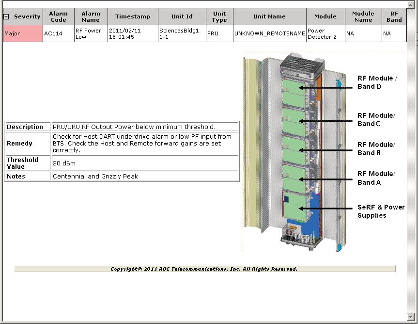
5 D OCUMENT OVERVIEW This reference guide lists the alarms that the FlexWave Element Management System (EMS) can generate. To assist you in troubleshooting a FlexWave system, a remedy for each alarm is also provided. This section tells you how to use this document. DOCUMENT REVISION HISTORY This is the second release of this document; it updates the definitions of the following alarms: "DART Fault on page 31 (Host Units), Alarm Code AC29, trap fwuhstdartfault "DART Fault on page 32 (Remote Units), Alarm Code AC101, trap fwurmtdartfault "RF Power Low on page 131, Alarm Code AC114, trap fwurmtrfpowerfault DOCUMENT CAUTIONS AND NOTES Two types of messages, identified below, may appear in the text: CAUTION! NOTE: Caution text indicates operations or steps that could cause personal injury, induce a safety problem in a managed device, destroy or corrupt information, or interrupt or stop services. Note text contains information about special circumstances. May 2017 CommScope, Inc. Page 1
6 Document Overview ABBREVIATIONS USED IN THIS ALARM REFERENCE AC Alternating Current IP Internet Protocol ALC Automatic Level Control IR Intermediate Reach Amp Amplifier LED Light-Emitting Diode BBU Baseband Unit LNA Low Noise Amplifier BER Bit Error Rate LPA Linear Power Amplifier BTS Base Transceiver Station LR Long Reach C Centigrade LVDS Low-Voltage Differential Signaling Cal Calibration MHz Megahertz CATV Community Activity Television MIB Management Information Base CDIU CPRI Digital Interface Unit MRAU Main Remote Access Unit CPRI Common Public Radio Interface PA Power Amplifier DART Digital Analog RF Transport PD Power Detector DART Digital-Analog Radio Transceiver PLL Phase-Locked Loop db Decibel PRU Prism Remote Unit dbfs Decibels relative to full scale PSU Power Supply Unit dbm Decibel-milliwatts RAI Remote Alarm Indication DC Direct Current RAU Remote Access Unit DCCS Distributed Coverage and Capacity Solutions RDI Remote DART Interface DRU DART Remote Unit REC Radio Equipment Controller EEPROM Electrically Erasable Programmable Read-Only Memory REF Reference EMEA Europe, Middle East, Africa REV Reverse EMG Expansion Module Group RF Radio Frequency EMS Element Management System Rx Receive F Fahrenheit SDI Slave Link Downstream Indication FPGA Field Programmable Gate Array SeRF Serial RF Freq Frequency SFP Small Form-Factor Pluggable FRU Fullband Remote Unit SNMP Simple Network Management Protocol FWD Forward SRAU Secondary Remote Access Unit GUI Graphical User Interface Tx Transmit HDM High Density Module URU Universal Radio Head Remote Unit HEU Host Expansion Unit Vdc Volts, direct current IF Intermediate Frequency VSWR Voltage Standing Wave Ratio IFEU IF Expansion Unit Page 2 May 2017 CommScope, Inc.
7 Document Overview FINDING AN ALARM IN THIS REFERENCE This document lists FlexWave alarms in alphabetical order by alarm name. However, you can also use the following document tools to find an alarm: Use the alphabetical "Index of Alarms on page 149 to locate an alarm definition quickly. Use the "Index of Alarm Codes on page 155 to find an alarm by its alarm code. Use the "Index of Traps on page 161 to find an alarm by its trap name. Alarm Reference Format The alarm reference uses the format shown below to list and define the FlexWave alarms and alarm remedies. Lists the user-readable alarm name, such as: Fan Fault Lists the unique alpha-numeric code assigned to the alarm by CommScope, such as AC1 or RUJ014. Lists the unique SNMP trap name assigned to the alarm. Note that the EMS GUI does not show trap names. This alarm reference provides traps for those who use an SNMP MIB browser to troubleshoot a FlexWave system. Traps are in the format of: fwuhstdartdcsupplyfault Identifies which unit and module has an alarm state, such as: Host Unit SeRF. Provides the meaning of the alarm and includes alarm thresholds, when applicable. Provides information as to what can cause the alarm, and the impact or affect that the alarm condition can have on the alarmed unit or system. Provides information on how to troubleshoot and clear the alarm. Identifies whether the alarm has a major, minor, or user-configurable alarm severity. UNIT TYPES The FlexWave EMS alarms are applicable to the following Prism and Spectrum units. Host Units Remote Units DART Remote Units (DRUs) Fullband Remote Units (FRUs), which are represented as PRU in the EMS GUI Host Expansion Units (HEUs) Prism Remote Units (PRUs). IF Expansion Units (IFEUs) Remote Access Units (RAUs). NOTE: Should a Remote Unit alarm not be applicable to all of the Remote Unit types, the alarm definition identifies the exception(s). May 2017 CommScope, Inc. Page 3
8 Document Overview UNDERSTANDING ALARM CODES For Host Units, HEUs, DRUs, FRUs, and PRUs, the alarm code comprises the letters AC followed by a numerical identifier unique to that alarm. For IFEUs and RAUs, the alarm codes indicate the following: 1st character identifies if the alarm is applicable to an IFEU or RAU I = IFEU R = RAU. 2nd character identifies the module type. If the alarm is applicable to an IFEU, the second character identifies the IFEU Module that is in an alarm state C = Controller Module F = FWD Module R = REV Module P = Power Module. If the alarm is applicable to a RAU, the second character is U. 3rd character identifies the alarm severity level J = N =. 4th - 6th characters a numerical identifier unique to that alarm. The alarm code ICN010 therefore indicates that the alarm is applicable to the IFEU Controller Module and that it is a minor alarm. ALARMS AND DRUS VERSUS HEUS In the System Tree, an HEU is identified as a DRU. However, as DRUs and HEUs should not be in the same system (HEUs can only be installed in a Prism Host-to-Host system), this should not cause confusion. In the EMS pages, an HEU can be identified as an HEU, an HEU Remote, or as a Remote. With the exceptions noted below, generic alarms that correspond to Remote Units also apply to the HEU. The DRU Temperature High alarm is generated when the ambient temperature for an HEU SeRF Module goes over 50 C. The DRU Temperature Low alarm is generated when the ambient temperature for an HEU SeRF Module goes below -5 C. HEUs do not support the Uplink Inactivity Fault. HEUs do not have LPAs, LNAs and PDs. Consequently, there will be no Remote Unit alarms related to Linear Power Amplifier (LPA), LNA and PD modules for HEUs. Page 4 May 2017 CommScope, Inc.
9 A LPHABETICAL LIST OF ALARMS 24 Vdc Out of Range ICN010 irsifeu24vdcfault IFEU Controller Module The internal 24 Vdc voltage of the IFEU Controller Module is outside of specification. This alarm state does not affect service to the IFEU. Replace the affected IFEU Controller Module. 3 Vdc Out of Range ICN011 irsifeu3vdcfault IFEU Controller Module The internal 3 Vdc voltage of the IFEU's Controller Module is outside of specification. This alarm state does not affect service to the IFEU. Replace the affected IFEU's Controller Module. 5 Vdc Out of Range ICN009 irsifeu5vdcfault IFEU Controller Module The internal 5 Vdc voltage of the IFEU's Controller Module is outside of specification. This alarm state does not affect service to the IFEU. Replace the affected IFEU's Controller Module. May 2017 CommScope, Inc. Page 5
10 54 Vdc Out of Range ICN013 irsifeu54vdcfault IFEU Controller Module The internal 54 Vdc voltage of the IFEU's Controller Module is outside of specification. This alarm state does not affect service to the IFEU. Replace the affected IFEU's Controller Module. 6 Vdc Out of Range ICN012 irsifeu6vdcfault IFEU Controller Module The internal 6 Vdc voltage of the IFEU's Controller Module is outside of specification. This alarm state does not affect service to the IFEU. Replace the affected IFEU's Controller Module. Antenna Port 1 Disconnect RUJ013 irsrauantennadisconnectport1fault Remote Access Unit Antenna disconnected or connected incorrectly (Ant Port 1). High VSWR detected for Antenna Port 1 during System Test, possibly resulting in loss of service for that band. Check the RAU Antenna Port 1 and antenna lead for correct frequency/band, and then retry System Test (System Configuration > Perform System Test). If alarm persists, connect a 50-Ohm terminator in place of the antenna and rerun System Test. If alarm persists with a 50-Ohm terminator, replace the RAU, otherwise replace the antenna. Page 6 May 2017 CommScope, Inc.
11 Antenna Port 1 Disconnect RUN013 irsrauantennaport1disconnectfault Remote Access Unit Antenna disconnected or connected incorrectly (Ant Port 1). Alphabetical List of Alarms High VSWR detected for Antenna Port 1 during System Test, possibly resulting in loss of service for that band. Check the RAU Antenna Port 1 and antenna lead for correct frequency/band, and then retry System Test (System Configuration > Perform System Test). If alarm persists, connect a 50-Ohm terminator in place of the antenna and rerun System Test. If alarm persists with a 50-Ohm terminator, replace the RAU, otherwise replace the antenna. Antenna Port 2 Disconnect RUJ014 irsrauantennadisconnectport2fault Remote Access Unit Antenna disconnected or connected incorrectly (Ant Port 2). High VSWR detected for Antenna Port 2 during System Test, possibly resulting in loss of service for that band. Check the RAU Antenna Port 2 and antenna lead for correct frequency/band, and then retry System Test (System Configuration > Perform System Test). If alarm persists, connect a 50-Ohm terminator in place of the antenna and rerun System Test. If alarm persists with a 50-Ohm terminator, replace the RAU, otherwise replace the antenna. Antenna Port 2 Disconnect RUN014 irsrauantennaport2disconnectfault Remote Access Unit Antenna disconnected or connected incorrectly (Ant Port 2). High VSWR detected for Antenna Port 2 during System Test, possibly resulting in loss of service for that band. Check the RAU Antenna Port 2 and antenna lead for correct frequency/band, then retry System Test (System Configuration > Perform System Test). If alarm persists, connect a 50-Ohm terminator in place of the antenna and rerun System Test. If alarm persists with a 50-Ohm terminator, replace the RAU, otherwise replace the antenna. May 2017 CommScope, Inc. Page 7
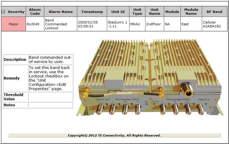
12 Band Commanded Lockout The Alarm Code and Trap are dependent on the RAU type and band that is alarming. The GUI identifies the actual band in alarm. Within an SNMP browser, the Trap indicates the affected path, as shown in the following table. Alarm Code Trap Path RUJ049 irsraubandpath1abandcommandedlockoutfault 1A RUJ050 irsraubandpath2abandcommandedlockoutfault 2A RUJ051 irsraubandpath3abandcommandedlockoutfault 3A RUJ052 irsraubandpath1bbandcommandedlockoutfault 1B RUJ053 irsraubandpath2bbandcommandedlockoutfault 2B RUJ054 irsraubandpath3bbandcommandedlockoutfault 3B Remote Access Unit The identified RAU band has been commanded out-of-service by user. Loss of service for the identified RAU band. To set the identified RAU band back in service, remove the check mark from the Lockout check box on the Unit Configuration > Edit Properties page. Band Fault Lockout The Alarm Code and Trap are dependent on the RAU type and band that is alarming. The GUI identifies the actual band in alarm. Within an SNMP browser, the Trap indicates the affected path, as shown in the following table. Alarm Code Trap Path RUJ057 irsraubandpath1abandfaultlockoutfault 1A RUJ058 irsraubandpath2abandfaultlockoutfault 2A RUJ059 irsraubandpath3abandfaultlockoutfault 3A RUJ060 irsraubandpath1bbandfaultlockoutfault 1B RUJ061 irsraubandpath2bbandfaultlockoutfault 2B RUJ062 irsraubandpath3bbandfaultlockoutfault 3B IFEU Controller Module Band commanded shutdown due to an active major alarm in a unit that is upstream (closer to the Host Unit). Loss of service for this band in the IFEU due to an active major alarm in an upstream unit. Check the Host Unit and DRU DARTs for major alarms (Alarms > View Current Alarms). Page 8 May 2017 CommScope, Inc.
13 Brownout Reset ICJ006 irsifeubrownoutresetfault IFEU Controller Module IFEU microprocessor brownout reset occurred and recovered. This alarm state does affect service to the IFEU. If this happens repeatedly, replace the IFEU Controller Module. Brownout Reset RUJ006 irsraubrownoutresetfault Remote Access Unit RAU microprocessor brownout reset occurred and recovered. This alarm state does not affect service to the RAU. If this happens repeatedly, replace the RAU. Cal Tone Not Present (Port 1) IFN025 irsifeuport1caltonenotpresentfault IFEU FWD Module Calibration test tone is not present (FWD IF OUT Port 1). Possible forward path failure, resulting in degraded or loss of service for RAUs connected to the FWD IF OUT Port 1. Run a System Test (System Configuration > Perform System Test). If alarm persists, replace the IFEU FWD Module. May 2017 CommScope, Inc. Page 9
14 Cal Tone Not Present (Port 2) IFN026 irsifeuport2caltonenotpresentfault IFEU FWD Module Calibration test tone is not present (FWD IF OUT Port 2). Possible forward path failure, resulting in degraded or loss of service for RAUs connected to the FWD IF OUT Port 2. Run a System Test (System Configuration > Perform System Test). If alarm persists, replace the IFEU FWD Module. Cal Tone Not Present (Port 3) IFN027 irsifeuport3caltonenotpresentfault IFEU FWD Module Calibration test tone is not present (FWD IF OUT Port 3). Possible forward path failure, resulting in degraded or loss of service for RAUs connected to the FWD IF OUT Port 3. Run a System Test (System Configuration > Perform System Test). If alarm persists, replace the IFEU FWD Module. Cal Tone Not Present (Port 4) IFN028 irsifeuport4caltonenotpresentfault IFEU FWD Module Calibration test tone is not present (FWD IF OUT Port 4). Possible forward path failure, resulting in degraded or loss of service for RAUs connected to the FWD IF OUT Port 4. Run a System Test (System Configuration > Perform System Test). If alarm persists, replace the IFEU FWD Module. Page 10 May 2017 CommScope, Inc.
15 Cal Tone Not Present (Port 5) IFN029 irsifeuport5caltonenotpresentfault IFEU FWD Module Calibration test tone is not present (FWD IF OUT Port 5). Possible forward path failure, resulting in degraded or loss of service for RAUs connected to the FWD IF OUT Port 5. Run a System Test (System Configuration > Perform System Test). If alarm persists, replace the IFEU FWD Module. Cal Tone Not Present (Port 6) IFN030 irsifeuport6caltonenotpresentfault IFEU FWD Module Calibration test tone is not present (FWD IF OUT Port 6). Possible forward path failure, resulting in degraded or loss of service for RAUs connected to the FWD IF OUT Port 6. Run a System Test (System Configuration > Perform System Test). If alarm persists, replace the IFEU FWD Module. Cal Tone Not Present (Port 7) IFN031 irsifeuport7caltonenotpresentfault IFEU FWD Module Calibration test tone is not present (FWD IF OUT Port 7). Possible forward path failure, resulting in degraded or loss of service for RAUs connected to the FWD IF OUT Port 7. Run a System Test (System Configuration > Perform System Test). If alarm persists, replace the IFEU FWD Module. May 2017 CommScope, Inc. Page 11
16 Cal Tone Not Present (Port 8) IFN032 irsifeuport8caltonenotpresentfault IFEU FWD Module Calibration test tone is not present (FWD IF OUT Port 8). Possible forward path failure, resulting in degraded or loss of service for RAUs connected to the FWD IF OUT Port 8. Run a System Test (System Configuration > Perform System Test). If alarm persists, replace the IFEU FWD Module. Cannot Power Up SRAU(s) RUJ022 irsraucantpowerupsraufault Remote Access Unit DC Voltage too low to power up SRAUs. Loss of service for affected SRAUs. Ensure that the IFEU power supply output is 54V. In the Unit Menu bar, click Diagnostics > Analyze RAU DC Voltage to see how close the DC voltage level is to the alarm threshold. Try connecting the MRAU to another IFEU FWD/REV port. If alarm persists, then check DC loss on FWD and REV CATV cables; otherwise do not use the previous port and replace the IFEU when possible. If high DC loss is measured on CATV cables, replace both cables with lower loss ones, or if length is the issue, use RG11 CATV cables. If alarm still remains, replace the MRAU. CDIU CPRI Port 1 Carrier Configuration Mismatch AC227 fwuhstcdiuport1carriercfgfault Host Unit CDIU A carrier configured by the REC on CDIU CPRI Port 1 does not fall completely within the frequency range of the mapped Path's passband. The CDIU Path was configured with a passband that does not match the REC carrier frequency range. RF is muted. Unlink the CDIU Path. Change the passband so that it includes the entire carrier frequency range and link the CDIU Path. Page 12 May 2017 CommScope, Inc.
17 CDIU CPRI Port 1 Module Missing Fault AC212 fwuhstcdiuport1optmissingfault Host Unit CDIU CDIU CPRI port 1 SFP is either not present or not responding. Loss of forward and reverse RF. Insert or replace the SFP. CDIU CPRI Port 1 Optical Over Drive AC208 fwuhstcdiuport1optoverdrivefault Host Unit CDIU CDIU CPRI Port 1 SFP optical receive input power above specification; the threshold is 1 dbm (IR) /-9dBm (LR). Missing or faulty optical attenuator, which can cause degradation or loss of RF. Reduce the optical receive level by adding optical attenuation. Replace optical attenuator if faulty. CDIU CPRI Port 1 Optical Rx High BER AC209 fwuhstcdiuport1optrxberfault Host Unit CDIU High bit error rate (BER) detected by fiber-optic receiver on CDIU CPRI Port 1; the threshold is Optical over-drive, dirty fiber-optic connection(s), or bend radius on the fiber-optic cable is exceeded. It is also possible that the SFP may be faulty. RF is affected. First check that the CDIU Rate (System Information > Configure CDIU Interfaces) is compatible with the connected BBU. If the CPRI Rate is correct then check for optical overdrive conditions (Unit Information > View Optical Ports). If RX Power is above specification, add external optical attenuation. If RX Power is below specification, remove attenuation. If problem remains, first ensure that the fiber-optic connection(s) between the CDIU and upstream unit are clean and fully seated, and then check for kinks or sharp bends in the fiber-optic cable. If unable to clear the alarm or correct any problems found, replace the fiber-optic cable. Check SFP and replace, if necessary. May 2017 CommScope, Inc. Page 13
18 CDIU CPRI Port 1 Optical Rx No Light AC210 fwuhstcdiuport1optrxnolightfault Host Unit CDIU No signal detected by optical receiver on CDIU CPRI Port 1. Unclean or missing fiber-optic cable, which can cause degradation or loss of RF. Check for broken fiber-optic cable, and replace if found. Check for disconnected fiber-optic cable, and reconnect cable if necessary. Check that the BBU has power. CDIU CPRI Port 1 Optical Transmitter Fault AC211 fwuhstcdiuport1optlaserfault Host Unit CDIU CDIU CPRI Port 1 SFP optical transmitter has failed, which affects RF service. Faulty SFP, which can cause degradation or loss of RF. Replace the SFP. CDIU CPRI Port 1 Optical Under Drive AC207 fwuhstcdiuport1optunderdrivefault Host Unit CDIU CDIU CPRI Port 1 SFP optical receive input power is below specification; the threshold is -18 dbm (IR) /-27 dbm (LR). Missing or faulty optical attenuator. Dirty fiber-optic connection or incorrect SFP type. Degradation or loss of RF. Check fiber-optic cable for too much attenuation and/or dirty connections. Check SFP type (wavelength or LR) being used. Replace the SFP if it is the wrong type. Page 14 May 2017 CommScope, Inc.
19 CDIU CPRI Port 1 REC Communication Fault AC225 fwuhstcdiuport1commsfault Host Unit CDIU Control and management channel with the REC on CDIU CPRI Port 1 has failed. REC has stopped managing the CDIU. RF is muted. Check REC status and its fiber-optic cable connection to CDIU. Verify REC Type configuration. CDIU CPRI Port 1 REC Type Configuration Mismatch AC226 fwuhstcdiuport1rectypecfgfault Host Unit CDIU User configured REC type on CDIU CPRI Port 1 is not supported by the CDIU. CDIU has been replaced. New CDIU does not support the configured REC Type. RF is muted. Replace CDIU. Update firmware on CDIU. Configure a different REC type. CDIU CPRI Port 1 Remote Alarm Indication (RAI) AC223 fwuhstcdiuport1raifault Host Unit CDIU The Remote Alarm Indication (RAI) bit is set in the received CPRI frame from the REC on CDIU CPRI Port 1. The upstream unit has detected a problem with the upstream fiber-optic cable. RF is muted. Check for problems with the uplink fiber-optic cable. May 2017 CommScope, Inc. Page 15
20 CDIU CPRI Port 1 Slave Link Downstream Indication (SDI) AC224 fwuhstcdiuport1sdifault Host Unit CDIU The Slave Link Downstream Indication (SDI) bit is set in the received CPRI frame from the REC on CDIU CPRI Port 1. There is a problem with fiber-optic communication in the cascade upstream of the CDIU. RF is muted. Check the fiber-optic cable on units upstream of the CDIU. CDIU CPRI Port 2 Carrier Configuration Mismatch AC234 fwuhstcdiuport2carriercfgfault Host Unit CDIU A carrier configured by the REC on CDIU CPRI Port 2 does not fall completely within the frequency range of the mapped Path's passband. The CDIU Path was configured with a passband that does not match the REC carrier frequency range. RF is muted. Unlink the CDIU Path. Change the passband so that it includes the entire carrier frequency range and link the CDIU Path. CDIU CPRI Port 2 Module Missing Fault AC220 fwuhstcdiuport2optmissingfault Host Unit CDIU CDIU CPRI port 2 SFP is either not present or not responding. Loss of forward and reverse RF. Insert or replace the SFP. Page 16 May 2017 CommScope, Inc.
21 CDIU CPRI Port 2 Optical Over Drive AC216 fwuhstcdiuport2optoverdrivefault Host Unit CDIU Alphabetical List of Alarms CDIU CPRI Port 2 SFP optical receive input power above specification; the threshold is 1 dbm (IR) /-9dBm (LR). Missing or faulty optical attenuator, which can cause degradation or loss of RF. Reduce the optical receive level by adding optical attenuation. Replace optical attenuator if faulty. CDIU CPRI Port 2 Optical Rx High BER AC217 fwuhstcdiuport2optrxberfault Host Unit CDIU High bit error rate (BER) detected by fiber-optic receiver on CDIU CPRI Port 2; the threshold is Optical over-drive, dirty fiber-optic connection(s), or bend radius on the fiber-optic cable is exceeded. It is also possible that the SFP may be faulty. RF is affected. Check for optical overdrive conditions (Unit Information > View Optical Ports). If Rx Power is above specification, add external optical attenuation. If Rx Power is below specification, remove attenuation. If problem remains, first ensure that the fiber-optic connection(s) between the CDIU and upstream unit are clean and fully seated, and then check for kinks or sharp bends in the fiber-optic cable. If unable to clear the alarm or correct any problems found, replace the fiber-optic cable. Check SFP and replace, if necessary. CDIU CPRI Port 2 Optical Rx No Light AC218 fwuhstcdiuport2optrxnolightfault Host Unit CDIU No signal detected by optical receiver on CDIU CPRI Port 2. Unclean or missing fiber-optic cable, which can cause degradation or loss of RF. Check for broken fiber-optic cable, and replace if found. Check for disconnected fiber-optic cable, and reconnect cable if necessary. Check that the BBU has power. May 2017 CommScope, Inc. Page 17
22 CDIU CPRI Port 2 Optical Transmitter Fault AC219 fwuhstcdiuport2optlaserfault Host Unit CDIU CDIU CPRI Port 2 SFP optical transmitter has failed, which affects RF service. Faulty SFP, which can cause degradation or loss of RF. Replace the SFP. CDIU CPRI Port 2 Optical Under Drive AC215 fwuhstcdiuport2optunderdrivefault Host Unit CDIU CDIU CPRI Port 2 SFP optical receive input power is below specification; the threshold is -18 dbm (IR) /-27 dbm (LR). Missing or faulty optical attenuator. Dirty fiber-optic connection or incorrect SFP type. Degradation or loss of RF. Check fiber-optic cable for too much attenuation and/or dirty connections. Check SFP type (wavelength or LR) being used. Replace the SFP if it is the wrong type. CDIU CPRI Port 2 REC Communication Fault AC232 fwuhstcdiuport2commsfault Host Unit CDIU Control and management channel with the REC on CDIU CPRI Port 2 has failed. REC has stopped managing the CDIU. RF is muted. Check REC status and its fiber-optic cable connection to CDIU. Verify REC Type configuration. Page 18 May 2017 CommScope, Inc.
23 CDIU CPRI Port 2 REC Type Configuration Mismatch AC233 fwuhstcdiuport2rectypecfgfault Host Unit CDIU User configured REC type on CDIU CPRI Port 2 is not supported by the CDIU. CDIU has been replaced. New CDIU does not support the configured REC Type. RF is muted. Replace CDIU. Update firmware on CDIU. Configure a different REC type. CDIU CPRI Port 2 Remote Alarm Indication (RAI) AC230 fwuhstcdiuport2raifault Host Unit CDIU The Remote Alarm Indication (RAI) bit is set in the received CPRI frame from the REC on CDIU CPRI Port 2. The upstream unit has detected a problem with the upstream fiber-optic cable. RF is muted. Check for problems with the uplink fiber-optic cable. CDIU CPRI Port 2 Slave Link Downstream Indication (SDI) AC231 fwuhstcdiuport2sdifault Host Unit CDIU The Slave Link Downstream Indication (SDI) bit is set in the received CPRI frame from the REC on CDIU CPRI Port 2. There is a problem with fiber-optic communication in the cascade upstream of the CDIU. RF is muted. Check the fiber-optic cable on units upstream of the CDIU. May 2017 CommScope, Inc. Page 19
24 CDIU Internal Fault AC201 fwuhstcdiuinternalfault Host Unit CDIU Internal CDIU problem due to a failure with one or more of the following components: internal communications, calibration EEPROM, watchdog, FPGA configuration. Internal problem with CDIU hardware, software or configuration; RF is lost. First, power cycle the CDIU either by physically removing, then re-inserting it, or by resetting the Host Unit; if alarm persists, replace the CDIU. CDIU Path A ALC Limiting AC240 fwuhstcdiupathaalclimitingfault Host Unit CDIU CDIU Path A forward path Automatic Level Control active; the threshold is -1.5 dbfs. The forward path digital input signal is too high for the Host Unit CDIU path A gain setting. This may result in gain limiting or over-driving of the LPA. May not affect service immediately. May cause loss of RF if the condition persists. Decrease the Additive Forward Gain (db) for CDIU Path A (System Configuration > Provision System > Forward RF > Forward Link Budget (CDIU)), or reduce the forward signal level from the BBU. CDIU Path A Over Drive AC237 fwuhstcdiupathaoverdrivefault Host Unit CDIU CDIU Path A forward RF input too high; the threshold is -0.5 dbfs. The forward path RF signal exceeds -0.5 dbfs peak, which may affect the forward RF. Reduce the forward gain of the affected Host Unit CDIU (Provision System > Forward RF > Forward Link Budget (CDIU)). Page 20 May 2017 CommScope, Inc.
25 CDIU Path A Test Tone Enabled AC239 fwuhstcdiupathatesttoneenablefault Host Unit CDIU Commissioning test tone is enabled for CDIU Path A, resulting in muted RF traffic. Commissioning tone has been enabled either through the GUI or via SNMP. RF is muted as long as the commissioning tone is active. Disable the commissioning test tone (System Configuration > Generate Test Tone). CDIU Path A Under Drive AC238 fwuhstcdiupathaunderdrivefault Host Unit CDIU CDIU Path A forward RF input signal is below the normal operating limit; threshold is [-45 dbfs] based upon the Peak power measurement (Provision System > Forward RF > Forward Link Budget (CDIU) > RMS Input Power (dbfs) Current Composite > Peak). CDIU forward path signal is not present or the CPRI input level and forward gain are not configured correctly. This can cause degradation to or loss of forward RF. Check the RF power levels of the Antenna Carriers of the affected Host Unit CDIU. Check the Power Allocation %. Increase the CDIU Additive Forward Gain (db) (Provision System > Forward RF > Forward Link Budget (CDIU)). CDIU Path B ALC Limiting AC247 fwuhstcdiupathbalclimitingfault Host Unit CDIU CDIU Path B forward path Automatic Level Control active; the threshold is -1.5 dbfs. The forward path digital input signal is too high for the Host Unit CDIU path B gain setting. This may result in gain limiting or over-driving of the LPA. May not affect service immediately. May cause loss of RF if the condition persists. Decrease the Additive Forward Gain (db) for CDIU Path B (Provision System > Forward RF > Forward Link Budget (CDIU)), or reduce the forward signal level from the BBU. May 2017 CommScope, Inc. Page 21
26 CDIU Path B Over Drive AC244 fwuhstcdiupathboverdrivefault Host Unit CDIU CDIU Path B forward RF input too high; the threshold is -0.5 dbfs. The forward path RF signal exceeds -0.5 dbfs peak, which may affect the forward RF. Reduce the forward gain of the affected Host Unit CDIU (Provision System > Forward RF > Forward Link Budget (CDIU)). CDIU Path B Test Tone Enabled AC246 fwuhstcdiupathbtesttoneenablefault Host Unit CDIU Commissioning test tone is enabled for CDIU Path B, resulting in muted RF traffic. Commissioning tone has been enabled either through the GUI or via SNMP. RF is muted as long as the commissioning tone is active. Disable the commissioning test tone (System Configuration > Generate Test Tone). CDIU Path B Under Drive AC245 fwuhstcdiupathbunderdrivefault Host Unit CDIU CDIU Path B forward RF input signal is below the normal operating limit; threshold is [-45 dbfs] based upon the Peak power measurement (Provision System > Forward RF > Forward Link Budget (CDIU) > RMS Input Power (dbfs) Current Composite > Peak). CDIU forward path signal is not present or the CPRI input level and forward gain are not configured correctly. This can cause degradation to or loss of forward RF. Check the RF power levels of the Antenna Carriers of the affected Host Unit CDIU. Check the Power Allocation %. Increase the CDIU Additive Forward Gain (db) (Provision System > Forward RF > Forward Link Budget (CDIU)). Page 22 May 2017 CommScope, Inc.
27 Clock Configuration Invalid AC38 fwuhstsyscardclockcfgfault Host Unit System Host Units with a CDIU require that the System Board III be configured for an external reference clock. System is currently configured to use the internal 10 MHz clock reference, but the CDIU requires an external reference, resulting in no RF for the CDIU bands. Change the 10 MHz Reference Clock selection to External (Host Unit Configuration >Edit Properties). Ensure that each CDIU has its REF OUT connected to the System Board EXT REF IN and that the Host Unit has a System Board III or higher. Clock Priority Level Conflict AC37 fwumastclockprioritylvlconflict Host Unit SeRF More than one Host Unit in a Multi-Host system has the same Clock Priority Level; all Host Units in conflict raise this alarm. At least two Host Units in a Multi-Host system have the same Clock Priority Level; this causes loss of RF. The Clock Priority Level Conflict alarm is a transient alarm. It will be cleared within 30 seconds, as the EMS automatically changes the Clock Priority Level on one or both of the Host Units so that the two Host Units have different clock priority values. If it is intended that a specific Host Unit should provide the master clock, the new priority values should be checked and adjusted manually if necessary. Contact Alarm Input 1 Active AC43 fwuhstcontactalarminput1 Host Unit SeRF Host Contact Alarm Input #1 active. The device connected to Contact Alarm input 1 is in alarm. Check equipment connected to Host Contact Alarm Input 1, or check contact polarity (i.e., Normally Open or Normally Closed). User Configurable May 2017 CommScope, Inc. Page 23
28 Contact Alarm Input 1 Active AC65 fwurmtcontactalarminput1 Remote Unit SeRF Remote Unit Contact Alarm Input #1 active. The device connected to Contact Alarm input 1 is in alarm. Check equipment connected to the Remote Unit Contact Alarm Input 1, or check contact polarity (i.e., Normally Open or Normally Closed). Contact Alarm Input 2 Active AC44 fwuhstcontactalarminput2 Host Unit SeRF Host Contact Alarm Input #2 active. The device connected to Contact Alarm input 2 is in alarm. Check equipment connected to Host Contact Alarm Input 2, or check contact polarity (i.e., Normally Open or Normally Closed). User Configurable Contact Alarm Input 2 Active AC66 fwurmtcontactalarminput2 Remote Unit SeRF Remote Unit Contact Alarm Input #2 active. The device connected to Contact Alarm input 2 is in alarm. Check equipment connected to Remote Unit Contact Alarm Input 2, or check contact polarity (i.e., Normally Open or Normally Closed). Page 24 May 2017 CommScope, Inc.
29 DART ALC Limiting AC33 fwuhstdartalclimitingfault Host Unit DART Host Unit DART forward path Automatic Level Control active; the threshold is +13 plus the configured Fully Loaded Input Power dbm. The forward path RF input signal is too high for the Host Unit DART forward path gain setting. This may result in gain limiting or over-driving of the LPA. May not affect service immediately. May cause loss of RF if the condition persists. Increase the Host Unit DART configured Fully Loaded Max Composite Power (Provision System > Forward RF> Forward Link Budget (RF Slots)), or reduce the RF signal level from the BTS/BDA. DART Communications Fault AC92 fwurmtdartcommsfault Remote Unit DART The Remote Unit DART communication path is missing or incorrect. The DART Communications Fault for Remote Units can also occur on HEUs. The following causes are possible: the fiber-optic communication path is missing or incorrect; the Host Unit DART or CDIU may be missing; the Host DART or CDIU is not compatible with the Remote Unit DART or they are configured differently; the Remote Unit DART is linked to the wrong Host Unit DART/CDIU or the wrong slot on the Host Unit; this causes loss of RF. Check if the Host Unit DART or CDIU is missing. If present, verify that it is compatible with the Remote Unit DART and/or configured correctly. Check the optical performance of the SFPs used to connect RF to the Remote Unit DART, including Tx/Rx levels and alarms. Resolve any optical problem and see if the alarm clears. If the optical path is good, then check whether the SFPs or fiber-optic cable have been moved. If either has been moved, restore to its original position. If original position is not available or is unknown, then perform a Clear Configuration on the Remote Unit DART (select the Remote Unit in System Tree, and then click Unit Configuration > Configure Slots) and re-link (System Configuration > Provision System > Linking). May 2017 CommScope, Inc. Page 25
30 DART Communications Fault Slot 1 AC161 fwurmtdartcommsslot1fault DART The Remote Unit DART communication path to Host Unit Slot 1 is missing or incorrect. The DART Communications Fault for Remote Units can also occur on HEUs. The following causes are possible: the fiber-optic communication path is missing or incorrect; the Host Unit DART or CDIU in Slot 1 may be missing; the Host DART or CDIU is not compatible with the Remote Unit DART or they are configured differently; the Remote Unit DART is linked to the wrong Host Unit DART/CDIU or the wrong slot on the Host Unit; this causes loss of RF. Check if the Host Unit DART or CDIU in Slot 1 is missing. If present, verify that it is compatible with the Remote Unit DART and/or configured correctly. Check the optical performance of the SFPs used to connect RF to the Remote Unit DART, including Tx/Rx levels and alarms. Resolve any optical problem and see if the alarm clears. If the optical path is good, then check whether the SFPs or fiber-optic cable have been moved. If either has been moved, restore to its original position. If original position is not available or is unknown, then perform a Clear Configuration on the Remote Unit DART (select the Remote Unit in System Tree, and then click Unit Configuration > Configure Slots) and re-link (System Configuration > Provision System > Linking). DART Communications Fault Slot 2 AC162 fwurmtdartcommsslot2fault DART The Remote Unit DART communication path to Host Unit Slot 2 is missing or incorrect. The DART Communications Fault for Remote Units can also occur on HEUs. The following causes are possible: the fiber-optic communication path is missing or incorrect; the Host Unit DART or CDIU in Slot 2 may be missing; the Host DART or CDIU is not compatible with the Remote Unit DART or they are configured differently; the Remote Unit DART is linked to the wrong Host Unit DART/CDIU or the wrong slot on the Host Unit; this causes loss of RF. Check if the Host Unit DART or CDIU in Slot 2 is missing. If present, verify that it is compatible with the Remote Unit DART and/or configured correctly. Check the optical performance of the SFPs used to connect RF to the Remote Unit DART, including Tx/Rx levels and alarms. Resolve any optical problem and see if the alarm clears. If the optical path is good, then check whether the SFPs or fiber-optic cable have been moved. If either has been moved, restore to its original position. If original position is not available or is unknown, then perform a Clear Configuration on the Remote Unit DART (select the Remote Unit in System Tree, and then click Unit Configuration > Configure Slots) and re-link (System Configuration > Provision System > Linking). Page 26 May 2017 CommScope, Inc.
31 DART Communications Fault Slot 3 AC163 fwurmtdartcommsslot3fault DART The Remote Unit DART communication path to Host Unit Slot 3 is missing or incorrect. The DART Communications Fault for Remote Units can also occur on HEUs. The following causes are possible: the fiber-optic communication path is missing or incorrect; the Host Unit DART or CDIU in Slot 3 may be missing; the Host DART or CDIU is not compatible with the Remote Unit DART or they are configured differently; the Remote Unit DART is linked to the wrong Host Unit DART/CDIU or the wrong slot on the Host Unit; this causes loss of RF. Check if the Host Unit DART or CDIU in Slot 3 is missing. If present, verify that it is compatible with the Remote Unit DART and/or configured correctly. Check the optical performance of the SFPs used to connect RF to the Remote Unit DART, including Tx/Rx levels and alarms. Resolve any optical problem and see if the alarm clears. If the optical path is good, then check whether the SFPs or fiber-optic cable have been moved. If either has been moved, restore to its original position. If original position is not available or is unknown, then perform a Clear Configuration on the Remote Unit DART (select the Remote Unit in System Tree, and then click Unit Configuration > Configure Slots) and re-link (System Configuration > Provision System > Linking). DART Communications Fault Slot 4 AC164 fwurmtdartcommsslot4fault DART The Remote Unit DART communication path to Host Unit Slot 4 is missing or incorrect. The DART Communications Fault for Remote Units can also occur on HEUs. The following causes are possible: the fiber-optic communication path is missing or incorrect; the Host Unit DART or CDIU in Slot 4 may be missing; the Host DART or CDIU is not compatible with the Remote Unit DART or they are configured differently; the Remote Unit DART is linked to the wrong Host Unit DART/CDIU or the wrong slot on the Host Unit; this causes loss of RF. Check if the Host Unit DART or CDIU in Slot 4 is missing. If present, verify that it is compatible with the Remote Unit DART and/or configured correctly. Check the optical performance of the SFPs used to connect RF to the Remote Unit DART, including Tx/Rx levels and alarms. Resolve any optical problem and see if the alarm clears. If the optical path is good, then check whether the SFPs or fiber-optic cable have been moved. If either has been moved, restore to its original position. If original position is not available or is unknown, then perform a Clear Configuration on the Remote Unit DART (select the Remote Unit in System Tree, and then click Unit Configuration > Configure Slots) and re-link (System Configuration > Provision System > Linking). May 2017 CommScope, Inc. Page 27
32 DART Communications Fault Slot 5 AC165 fwurmtdartcommsslot5fault DART The Remote Unit DART communication path to Host Unit Slot 5 is missing or incorrect. The DART Communications Fault for Remote Units can also occur on HEUs. The following causes are possible: the fiber-optic communication path is missing or incorrect; the Host Unit DART or CDIU in Slot 5 may be missing; the Host DART or CDIU is not compatible with the Remote Unit DART or they are configured differently; the Remote Unit DART is linked to the wrong Host Unit DART/CDIU or the wrong slot on the Host Unit; this causes loss of RF. Check if the Host Unit DART or CDIU in Slot 5 is missing. If present, verify that it is compatible with the Remote Unit DART and/or configured correctly. Check the optical performance of the SFPs used to connect RF to the Remote Unit DART, including Tx/Rx levels and alarms. Resolve any optical problem and see if the alarm clears. If the optical path is good, then check whether the SFPs or fiber-optic cable have been moved. If either has been moved, restore to its original position. If original position is not available or is unknown, then perform a Clear Configuration on the Remote Unit DART (select the Remote Unit in System Tree, and then click Unit Configuration > Configure Slots) and re-link (System Configuration > Provision System > Linking). DART Communications Fault Slot 6 AC166 fwurmtdartcommsslot6fault DART The Remote Unit DART communication path to Host Unit Slot 6 is missing or incorrect. The DART Communications Fault for Remote Units can also occur on HEUs. The following causes are possible: the fiber-optic communication path is missing or incorrect; the Host Unit DART or CDIU in Slot 6 may be missing; the Host DART or CDIU is not compatible with the Remote Unit DART or they are configured differently; the Remote Unit DART is linked to the wrong Host Unit DART/CDIU or the wrong slot on the Host Unit; this causes loss of RF. Check if the Host Unit DART or CDIU in Slot 6 is missing. If present, verify that it is compatible with the Remote Unit DART and/or configured correctly. Check the optical performance of the SFPs used to connect RF to the Remote Unit DART, including Tx/Rx levels and alarms. Resolve any optical problem and see if the alarm clears. If the optical path is good, then check whether the SFPs or fiber-optic cable have been moved. If either has been moved, restore to its original position. If original position is not available or is unknown, then perform a Clear Configuration on the Remote Unit DART (select the Remote Unit in System Tree, and then click Unit Configuration > Configure Slots) and re-link (System Configuration > Provision System > Linking). Page 28 May 2017 CommScope, Inc.
33 DART Communications Fault Slot 7 AC167 fwurmtdartcommsslot7fault DART The Remote Unit DART communication path to Host Unit Slot 7 is missing or incorrect. The DART Communications Fault for Remote Units can also occur on HEUs. The following causes are possible: the fiber-optic communication path is missing or incorrect; the Host Unit DART or CDIU in Slot 7 may be missing; the Host DART or CDIU is not compatible with the Remote Unit DART or they are configured differently; the Remote Unit DART is linked to the wrong Host Unit DART/CDIU or the wrong slot on the Host Unit; this causes loss of RF. Check if the Host Unit DART or CDIU in Slot 7 is missing. If present, verify that it is compatible with the Remote Unit DART and/or configured correctly. Check the optical performance of the SFPs used to connect RF to the Remote Unit DART, including Tx/Rx levels and alarms. Resolve any optical problem and see if the alarm clears. If the optical path is good, then check whether the SFPs or fiber-optic cable have been moved. If either has been moved, restore to its original position. If original position is not available or is unknown, then perform a Clear Configuration on the Remote Unit DART (select the Remote Unit in System Tree, and then click Unit Configuration > Configure Slots) and re-link (System Configuration > Provision System > Linking). DART Communications Fault Slot 8 AC168 fwurmtdartcommsslot8fault DART The Remote Unit DART communication path to Host Unit Slot 8 is missing or incorrect. The DART Communications Fault for Remote Units can also occur on HEUs. The following causes are possible: the fiber-optic communication path is missing or incorrect; the Host Unit DART or CDIU in Slot 8 may be missing; the Host DART or CDIU is not compatible with the Remote Unit DART or they are configured differently; the Remote Unit DART is linked to the wrong Host Unit DART/CDIU or the wrong slot on the Host Unit; this causes loss of RF. Check if the Host Unit DART or CDIU in Slot 8 is missing. If present, verify that it is compatible with the Remote Unit DART and/or configured correctly. Check the optical performance of the SFPs used to connect RF to the Remote Unit DART, including Tx/Rx levels and alarms. Resolve any optical problem and see if the alarm clears. If the optical path is good, then check whether the SFPs or fiber-optic cable have been moved. If either has been moved, restore to its original position. If original position is not available or is unknown, then perform a Clear Configuration on the Remote Unit DART (select the Remote Unit in System Tree, and then click Unit Configuration > Configure Slots) and re-link (System Configuration > Provision System > Linking). May 2017 CommScope, Inc. Page 29
34 DART DC Supply Fault AC28 fwuhstdartdcsupplyfault Host Unit DART DC supply voltages to the Host Unit DART(s) are outside specification Low voltage supply to the Host Unit DART(s); this can cause loss of RF if the condition is persistent. Check whether the Host Unit supply voltage is in the range of Vdc. If the voltage is correct and the alarm persists for five minutes (may be transient on startup), replace the Host Unit DART. DART DC Supply Fault AC97 fwurmtdartdcsupplyfault Remote Unit DART DC supply voltages for a Remote Unit DART are outside specification. Causes at the Remote Unit include: DART power up transient; bad AC input power; or faulty DART. Loss of RF if condition is persistent. If the alarm persists for five minutes (may be transient on startup), replace the Remote Unit DART. DART Downconverter 1 Synthesizer Unlocked AC25 fwuhstdartdwncon1synlockfault Host Unit DART Host Unit DART downconverter 1 synthesizer is unlocked. Startup transient or faulty Host Unit DARTs; this can cause loss of RF if the condition is persistent. The Downconverter 1 Synthesizer Unlocked alarm can occur during Host Unit reboots and DART Module hot swaps. If the alarm persists after five minutes, replace the Host Unit DART. Page 30 May 2017 CommScope, Inc.
35 DART Downconverter 2 Synthesizer Unlocked AC26 fwuhstdartdwncon2synlockfault Host Unit DART Host Unit DART downconverter 2 synthesizer unlocked. Startup transient or faulty Host Unit DARTs; this can cause loss of RF if the condition is persistent. The Downconverter 2 Synthesizer Unlocked alarm can occur during Host Unit reboots and DART Module hot swaps. If the alarm persists after five minutes, replace the Host Unit DART. DART Fault AC29 fwuhstdartfault Host Unit DART or CDIU Summary of the DART FPGA status and the following DART alarms: Downconverter 1 Synthesizer Unlocked, Downconverter 2 Synthesizer Unlocked, Upconverter Synthesizer Unlocked, and DART DC Supply Fault. For CDIUs, this alarm indicates a problem with the connection into the backplane (LVDS signals). Startup transient or faulty Host Unit DARTs/CDIUs; this can cause loss of RF if the condition is persistent. Inspect alarms (Alarms > View Current Alarms) for upconverter, downconverter, or DC supply alarms on the same Host Unit DART/CDIU, and then follow the corresponding alarm remedies. If none of these alarms are found, unseat and then reseat the DART/CDIU in the Host Unit chassis. If the alarm persists, do the following in the order presented, moving on to the next step only if the current step does not resolve the issue: 1 Unseat and then reseat the SeRF Module in the Host Unit chassis. 2 Replace the DART/CDIU. 3 Replace the SeRF Module. 4 Replace the Host Unit. May 2017 CommScope, Inc. Page 31
FlexWave Host Unit and Host Expansion Unit
 SENSE1 SENSE2 NO COM NO NO COM NO NO COM NO NO COM NO IN GND IN GND FlexWave Host Unit and Host Expansion Unit Module Replacement Guide October 2017 Host Unit II FAN SeRF II NETWORK CRAFT TX 8 RX TX 6
RF SCOUT PLUS INSTRUCTION MANUAL. Dielectric, LLC 22 Tower Rd. Raymond, ME Phone: January 2015, Rev B 1
 RF SCOUT PLUS INSTRUCTION MANUAL Dielectric, LLC 22 Tower Rd. Raymond, ME 04071 Phone: 800.341.9678 www.dielectric.com 21 January 2015, Rev B 1 WARNING Powering RF sensors above +30dBm (1W) will cause
Advanced Power Monitor (APM)
") Advanced Power Monitor (APM) What is the APM? The Advanced Power Monitor (APM) is used to monitor and measure the RF coverage performance determining characteristics of a communications site, on an individual
Advanced Power Monitor (APM) What is the APM? The Advanced Power Monitor (APM) is used to monitor and measure the RF coverage performance determining characteristics of a communications site, on an individual
RC802/ B 8E1 Modular Fiber-Optic Multiplexer (Rev. M) User Manual
 User Manual") RC802/804-240B 8E1 Modular Fiber-Optic Multiplexer (Rev. M) User Manual Raisecom Technology Co., Ltd. (04/2005) 1. Cautions Please read the following notices carefully before installing and using the device,
RC802/804-240B 8E1 Modular Fiber-Optic Multiplexer (Rev. M) User Manual Raisecom Technology Co., Ltd. (04/2005) 1. Cautions Please read the following notices carefully before installing and using the device,
Simplex Panel Interface Guide
 Simplex Panel Interface Guide February 2016 SATEON Software Integrations Simplex Panel Interface Guide Issue 1.0, released February 2016 Disclaimer Copyright 2016, Grosvenor Technology. All rights reserved.
Smart Combiners Installation Guide. For Obvius A89DC-08 sensor modules
 For Obvius A89DC-08 sensor modules Introduction Large roof and ground arrays connect the panels into stings that are merged together in combiner boxes. Each string will typically consist of 10-15 panels
GPS Evaluation Kit EVA1037/1080
 GPS Evaluation Kit An evaluation system for Tyco Electronics GPS modules A1037-A & A1080-A User s Manual Version 2.0 Hardware Revision 01 This page was intentionally left blank. Revision History Revision
OTEB-CO-B EDFA WITHOUT SNMP INSTRUCTION MANUAL
 OTEB-CO-B EDFA WITHOUT SNMP INSTRUCTION MANUAL Phone: (209) 586-022 (800) 545-022 Fax: (209) 586-026 E-Mail: salessupport@olsontech.com www.olsontech.com OTEB-CO-B (No SNMP) Rev. X7 /7/200 SAFETY WARNINGS
BTI7800 Series Alarm and Troubleshooting Guide
 BTI7800 Series Alarm and Troubleshooting Guide Juniper Networks, Inc. 1133 Innovation Way Sunnyvale, CA 94089 USA Part Number: Document Version: Published: Type: tel: 408-745-2000 BT8A78PD0021 01 November
System Connection in ibwave Design TE Connectivity Spectrum Product Line. Product: ibwave Design Version: and higher Published:
 System Connection in ibwave Design TE Connectivity Spectrum Product Line Product: ibwave Design Version: 5.2.7 and higher Published: 2011-05-09 ibwave SOLUTIONS INC. 2011 All Rights Reserved The information
RION ORION TELECOM NETWORKS INC. E2, 2Mbps x 4 Opti-Multiplexer Integrated E2, OLTE and Multiplexer. Product Brochure & Data Sheet TELECOM NETWORKS
 RION TELECOM NETWORKS ORION TELECOM NETWORKS INC. E2, 2Mbps x 4 Opti-Multiplexer Integrated E2, OLTE and Multiplexer Product Brochure & Data Sheet Headquarters: Phoenix, Arizona 20100, N 51st Ave, Suite
LCP-6144A4EDRx. 10GBASE-SR SFP+ Optical Transceiver FEATURES. Description. Applications. RoHS compliant. Compliant to SFP+ Electrical MSA SFF-8431
 10GBASE-SR SFP+ Optical Transceiver FEATURES RoHS compliant Compliant to SFP+ Electrical MSA SFF-8431 Compliant with SFF-8472 MSA Compliant with CPRI protocols for wireless base station Standard LC duplex
Digivance CXD/NXD Element Management System EMS. User Manual ADCP Part Number Rev A Issue 1
 Digivance CXD/NXD Element Management System EMS User Manual ADCP-75-199 Part Number 1344755 Rev A Issue 1 Page ii About This Manual This manual tells how to install and use the Digivance CXD/NXD Element
Refrigeration Controller Operator s Manual (HRC) PO Box 6183 Kennewick, WA
 PO Box 6183 Kennewick, WA") Refrigeration Controller Operator s Manual (HRC) PO Box 6183 Kennewick, WA 99336 www.jmcvr.com 1-509-586-9893 Table of Contents TABLE OF FIGURES...1 OVERVIEW OF THE HRC CAPABILITIES...2 INSTALLATION AND
Refrigeration Controller Operator s Manual (HRC) PO Box 6183 Kennewick, WA 99336 www.jmcvr.com 1-509-586-9893 Table of Contents TABLE OF FIGURES...1 OVERVIEW OF THE HRC CAPABILITIES...2 INSTALLATION AND
RAy SNMP. Application notes.
 Application notes. RAy SNMP. version 1.0 12/29/2017 RACOM s.r.o. Mirova1283 59231 Nove MestonaMorave CzechRepublic Tel.: +420565659 511 Fax: +420565659 512 E-mail: racom@racom.eu www.racom.eu Table of
Meridian wiredhart. HART Field Device Specification Goldmine Rd. Monroe, NC USA
 HART Field Device Specification Meridian wiredhart 4320 Goldmine Rd. Monroe, NC 28110 USA HART is a registered trademark of the HART Communication Foundation TABLE OF CONTENTS 1. Introduction...5 1.1 Scope...5
DSGH. Radiation-Based Detector with GEN2000 Electronics for Density Measurement QUICK REFERENCE GUIDE
 DSGH Radiation-Based Detector with GEN2000 Electronics for Density Measurement QUICK REFERENCE GUIDE Revision History Revision History Version of manual Description Date 1.0 Initial release 051025 1.1
RC801/803/ B 16E1 Fiber-Optic Multiplexer (Rev. M) User Manual. Raisecom Technology Co., Ltd. (04/2005)
 User Manual. Raisecom Technology Co., Ltd. (04/2005)") RC801/803/805-480B 16E1 Fiber-Optic Multiplexer (Rev. M) User Manual Raisecom Technology Co., Ltd. (04/2005) 1. Cautions Please read the following notices carefully before installing and using the device,
RC801/803/805-480B 16E1 Fiber-Optic Multiplexer (Rev. M) User Manual Raisecom Technology Co., Ltd. (04/2005) 1. Cautions Please read the following notices carefully before installing and using the device,
DS9400 Series. Release Notes for Firmware V2.07. Fire Alarm Control Panel
 DS9400 Series EN Release Notes for Firmware V2.07 Fire Alarm Control Panel DS9400 Series Release Notes for Firmware V2.07 Trademarks Trademarks Gentex is a trademark of Gentex Corporation, Fire Protection
UNC100 Integra Manual
 UNC100 Integra Manual New Generation Building Security July 30, 2014 V1.2 Copyright Notice Copyright 1995-2014 by All rights reserved Worldwide. Printed in Canada. This publication has been provided pursuant
DDT-4691 & DDR ASI / SD-SDI 8 Channel Mux Fibre Optic Link. User Manual. IRT Electronics Pty Ltd
 ASI / SD-SDI 8 Channel Mux Fibre Optic Link User Manual Revision 00 ASI / SD-SDI 8 Channel Mux Fibre Optic Link Revision History: Revision Date By Change Description Applicable to: 00 03/06/2014 AL Original
ACCURATE ELECTRONICS INC PO BOX SW HALL BLVD BEAVERTON OR USA FAX
 Page 1 of 10 Model 10807800 January 2014 ACCURATE ELECTRONICS INC PO BOX 1654 97075-1654 8687 SW HALL BLVD 97008 BEAVERTON OR USA 503.641.0118 FAX 503.646.3903 WWW.ACCURATE.ORG Practice Section 10807800
Added password for IP setup page : Password must be in IP format!
 NETWORK POWER MONITOR Release : 21 August 2014 Hardware Version : Version 7 Firmware version 1.00 PC Application Software : Version (latest)...2 Added password for IP setup page : Password must be in IP
Touchpad Exit Controller Administration Guide
 Touchpad Exit Controller Administration Guide 2018 RF Technologies, Inc. All specifications subject to change without notice. All Rights Reserved. No Part of this work may be reproduced or copied in any
RPM1600 Series Room Pressure Monitors
 RPM1600 Series Room Pressure Monitors Technical Bulletin LB-RPM1611-0, LB--0 Code No. LIT-12012228 Issued October 2017 Refer to the QuickLIT website for the most up-to-date version of this document. How
A1UL PERS. Personal Emergency Response System. For Technical Support Please Contact Your Service Provider Or Distributor
 A1UL PERS Personal Emergency Response System TABLE OF CONTENTS 1. READ THIS FIRST... 1 2. SYSTEM OVERVIEW.. 1 3. COMPONENTS 2 4. UNIT OPERATION! Standby Mode.. 3! Emergency Activation. 3! Answering Incoming
Carbon Monoxide Transmitter
 Introduction The CO Transmitter uses an electrochemical sensor to monitor the carbon monoxide level and outputs a field-selectable 4-20 ma or voltage signal. The voltage signal may also be set to 0-5 or
Essentials of Fiber to the Antenna: Fronthaul Installation Test
 Solution Brief Essentials of Fiber to the Antenna: Fronthaul Installation Test VIAVI Solutions 1 Fiber Inspection and Connectivity 3 Fronthaul Installation Test 2 Cable and Antenna Testing 4 Fiber Certification
4 Channel Contact Closure SFP DIN Fiber Link System
 USER GUIDE The leader in rugged fiber optic technology. U- 07A-0707 Channel Contact Closure DIN Fiber Link System Installation and Configuration Information Description The system provides transmission
Analog Input Module IC670ALG630
 1 IC670ALG630 The Thermocouple (IC670ALG630) accepts 8 independent thermocouple or millivolt inputs. Module features include: Self calibration Two data acquisition rates based on 50 Hz and 60 Hz line frequencies
Fratech Multipath-IP
 Rev 2.0 (May 2013) Installer Manual 1 Current Part Numbers: Fratech Multipath-IP E-Link STU PCB & Accessory Kit only In Metal Enclosure with Power Supply 998325-PK 998325-XS Installer Manual This document
4009 Fiber Optic Link Option Installation Instructions
 4009 Fiber Optic Link Option Installation Instructions Cautions and Warnings DO NOT INSTALL ANY SIMPLEX PRODUCT THAT APPEARS DAMAGED. Upon unpacking your Simplex product, inspect the contents of the carton
4590 Tank Side Monitor. Service Manual. WM550 Communication Protocol. Software Versionv2.03 SRM011FVAE0808
 SRM011FVAE0808 4590 Tank Side Monitor WM550 Communication Protocol Service Manual Software Versionv2.03 www.varec.com Varec, Inc. 5834 Peachtree Corners East, Norcross (Atlanta), GA 30092 USA Tel: +1 (770)
MODEL 8143 SIGNAL SELECTOR INSTALLATION AND OPERATION MANUAL
 MODEL 8143 SIGNAL SELECTOR INSTALLATION AND OPERATION MANUAL 95 Methodist Hill Drive Rochester, NY 14623 Phone: US +1.585.321.5800 Fax: US +1.585.321.5219 www.spectracomcorp.com Part Number 8143-5000-0050
Electronic Circuit Controller
 Union Switch & Signal Inc., an Ansaldo Signal company 1000 Technology Drive, Pittsburgh, PA 15219 645 Russell Street, Batesburg, SC 29006 SM 9020, Field Test Unit (N42252601) for the Electronic Circuit
IRIS Touch Quick Installation & Maintenance Guide. Version 1.0
 IRIS Touch Quick Installation & Maintenance Guide Version 1.0 Page 2 of 16 IRIS Touch Quick Installation & Maintenance Guide Version 1.0 Contents 1. Introduction... 4 2. Product Features... 4 3. Package
Code Alert Series 30 Software User Guide
 Code Alert Series 30 Software User Guide 2018 RF Technologies, Inc. All specifications subject to change without notice. All Rights Reserved. No Part of this work may be reproduced or copied in any form
Solution 880 Operators Manual. Issue 1.00
 Solution 880 Operators Manual Issue 1.00 Solution 880 Operators Manual Copyright 1998 by, SYDNEY, AUSTRALIA Document Part Number MA408O Document ISSUE 1.00 Printed 15 June 1998 This documentation is provided
Module Features are-configurable, no module jumpers to set
 December 2011 PACSystems* RX3i Isolated Thermocouple Input Module, 6 Channels, IC695ALG306 Isolated Thermocouple Input Module, 12 Channels, IC695ALG312 Isolated Thermocouple Input module IC695ALG306 provides
Instruction Manual Model Backup Switch, 1 for 8
 Instruction Manual Model 2582-282 Backup Switch, 1 for 8 December 2011, Rev. 0 MODEL 2582 SWITCH CROSS TECHNOLOGIES INC. SWITCH ALARM PSA PSB ALARM OFFLINE ONLINE UNIT STATUS 1 2 3 4 5 6 7 8 BU PROT MODE
SAFETY INFORMATION AND WARNINGS
 This manual refers to the Model SST-3 control panel manufactured since October 31, 2013, which uses a universal (100 277 VAC; 50/60 Hz) power supply. Older units use a voltage-specific power supply and
fmap Log / Troubleshooting Manual Release 8.0 Issue 1
 613-000626 Rev.A 061006 fmap Log / Troubleshooting Manual Release 8.0 Issue 1 2006 Allied Telesis Holdings K.K. All rights reserved. Information subject to change without notice. About this Manual This
Fratech Multipath-IP STU
 Rev 2.41 (September 2008) Installer Manual 1 Fratech Multipath-IP STU P/Nos: Single SIM: 998304OPT/998304TEL Dual SIM: 998307OPT/998307TEL Installer Manual This document contains a product overview, specifications
RMS/RPX Reader. User Manual
 RMS/RPX Reader User Manual Copyright Disclaimer Trademarks and patents Intended use FCC compliance Copyright 2005, GE Security Inc. All rights reserved. This document may not be copied or otherwise reproduced,
PACSystems* RX3i. Thermocouple Input Module, 12 Channels, IC695ALG412. GFK-2578B October 2011
 October 2011 PACSystems* RX3i Thermocouple Input Module, 12 Channels, IC695ALG412 The PACSystems * Thermocouple Input module IC695ALG412 provides twelve isolated differential thermocouple input channels.
Optical Fiber Monitor (OFM) Whitebox WB-OFM-1262-DC
 Whitebox WB-OFM-1262-DC") Optical Fiber Monitor (OFM) Whitebox WB-OFM-1262-DC www.lumentum.com Data Sheet The Lumentum Optical Fiber Monitor (OFM) Whiteboxes reduce network downtime with automated fault location. Detecting and
Optical Fiber Monitor (OFM) Whitebox WB-OFM-1262-DC www.lumentum.com Data Sheet The Lumentum Optical Fiber Monitor (OFM) Whiteboxes reduce network downtime with automated fault location. Detecting and
ICS Regent. Fire Detector Input Modules PD-6032 (T3419)
") ICS Regent Fire Detector Input Modules (T3419) Issue 1, March, 06 Fire detector input modules provide interfaces for 16 fire detector inputs such as smoke detectors, flame detectors, temperature detectors,
ICS Regent Fire Detector Input Modules (T3419) Issue 1, March, 06 Fire detector input modules provide interfaces for 16 fire detector inputs such as smoke detectors, flame detectors, temperature detectors,
CODE ALERT Enterprise Software User Guide
 CODE ALERT Enterprise Software User Guide 2018 RF Technologies, Inc. All specifications subject to change without notice. All Rights Reserved. No Part of this work may be reproduced or copied in any form
MODBUS MESSAGING to the S5 BATTERY VALIDATION SYSTEM
 BTECH, Inc. 10 Astro Place Rockaway, NJ 07866 MODBUS MESSAGING to the S5 BATTERY VALIDATION SYSTEM Users Guide Rev 1.6 09OCT15 1.0 Description This feature of the S5 allows a plant computer (DCS) to monitor
Contents. Glossary
 Contents Glossary ------------------------------------------------------------------------------------------------------ 6 1. Introduction to the IDS 1632 -------------------------------------------------------------
Contact Product Manager, with details of the application.
 Eaton Corporation Telecommunications Power Solutions Email: dc.info@eaton.com www.eaton.com/telecompower Application Note AN0100 SC200 SNMP Traps Last updated 14 June 2011 Applicable products Audience
NGC-UIT2 MODBUS PROTOCOL INTERFACE MAPPING FOR NGC-30 SYSTEMS. Firmware versions up to V2.0.X
 NGC-UIT2 MODBUS PROTOCOL INTERFACE MAPPING FOR NGC-30 SYSTEMS Firmware versions up to V2.0.X INDUSTRIAL HEAT TRACING SOLUTIONS EN-RaychemNGCUIT2Protocol-IM-H57880 06/15 1/32 Contents Section I Introduction
Figure 1. Proper Method of Holding the ToolStick. Figure 2. Improper Method of Holding the ToolStick
 CAN OBD READER REFERENCE DESIGN KIT USER GUIDE 1. Standard ToolStick Handling Recommendations The ToolStick Base Adapter and daughter cards are distributed without any protective plastics. To prevent damage
C-Bus Four Channel General Input Unit Installation Instructions
 C-Bus Four Channel General Input Unit Installation Instructions 5504GI Series REGISTERED DESIGN REGISTERED PATENT Table of Contents Section...Page 1.0 Product Range... 3 2.0 Description... 3 3.0 Capabilities...
Alarm Panel [ PRELIMINARY HARDWARE MANUAL ] USER MANUAL. v1.0a. May 7, 2008 D-OC-UM
![Alarm Panel [ PRELIMINARY HARDWARE MANUAL ] USER MANUAL. v1.0a. May 7, 2008 D-OC-UM](/thumbs/86/93788073.jpg "Alarm Panel [ PRELIMINARY HARDWARE MANUAL ] USER MANUAL. v1.0a. May 7, 2008 D-OC-UM") Alarm Panel USER MANUAL [ PRELIMINARY HARDWARE MANUAL ] Visit our website at www.dpstelecom.com for the latest PDF manual and FAQs. May 7, 2008 D-OC-UM085.07010 v1.0a Revision History April 28, 2008 May
Alarm Panel USER MANUAL [ PRELIMINARY HARDWARE MANUAL ] Visit our website at www.dpstelecom.com for the latest PDF manual and FAQs. May 7, 2008 D-OC-UM085.07010 v1.0a Revision History April 28, 2008 May
Optical Return Loss Measurement by Gregory Lietaert, Product Manager
 White Paper Optical Return Loss Measurement by Gregory Lietaert, Product Manager Introduction With the increasing frequency of high-speed transmission systems and DWDM deployment, optical return loss (ORL)
ACCURATE ELECTRONICS INC
 ACCURATE ELECTRONICS INC Page 1 of 7 Model 108078 2 Sept 09 WWW.ACCURATE.ORG PO BOX 1654 97075-1654 8687 SW Hall Blvd 97008 BEAVERTON OR USA 503.641.0118 FAX 503.646.3903 Practice Section 108078 Rev A
P2267 NETWORK INTERFACE
 P2267 NETWORK INTERFACE USER MANUAL FOR OPERATING SYSTEMS: 22031-03 23636-01 October 2009 Associated Controls (Australia) Pty. Limited 2-4 Norfolk Road Greenacre, NSW, 2190. PH +61 2 9642 4922, FAX +61
ZITON RADIO LOOP MODULE
 ZITON RADIO LOOP MODULE PROGRAMMING MANUAL Table of Contents Section Page No 1.0 INTRODUCTION...3 1.1 System Design...3 1.2 Handling Precautions...3 1.3 Packaging:...3 2.0 MENU STRUCTURE...4 2.1 Menu Structure
ProCon 16, 31, 47, 75, 77 & HT. RVA 46. Zone Controller Commissioning Data.
 ProCon 16, 31, 47, 75, 77 & HT. RVA 46. Zone Controller Commissioning Data. The RVA 46 Zone Controller can only be used in conjunction with a RVA47 controlled boiler installation. The RVA46 controller
FUSION ALARMS TROUBLESHOOTING GUIDE CURRENT LIMIT VOLTAGE LIMIT
 1 FUSION ALARMS TROUBLESHOOTING GUIDE CURRENT LIMIT Description: Controller is limiting the load current to the current limit set on the controller. Display: CURRENT LIMIT Alarm Reset Action: Automatically
The system is expanded via the RCC network with each RCC capable of passing information to and from up to 31 detection or output devices.
 FireCell Radio Hub Fully addressable Wireless activation Third party approved (EN54) 2-way radio communication Loop powered Diagnostics port Range in excess of 150 metres Overview The model FCX-500-001
Monitoring Operator Guide. Access Control Manager Software Version
 Monitoring Operator Guide Access Control Manager Software Version 5.10.10 2018, Avigilon Corporation. All rights reserved. AVIGILON, the AVIGILON logo, ACCESS CONTROL MANAGER, ACM, ACM VERIFY AND TRUSTED
FlameGard 5 UV/IR HART
 FlameGard 5 UV/IR HART HART Communication Manual The information and technical data disclosed in this document may be used and disseminated only for the purposes and to the extent specifically authorized
LCP-10G3B4QDRx-G. 10GBASE-LR SFP+ Optical Transceiver FEATURES. Description. Applications. Performance. RoHS compliant
 10GBASE-LR SFP+ Optical Transceiver FEATURES RoHS compliant Compliant to SFP+ Electrical MSA SFF-8431 Compliant with SFF-8472 MSA Standard LC duplex fiber-optic connector I 2 C for integrated Digital Optical
NU2 Smart Power Supply (SPS) Manual
 Manual") GENERAL The Smart Power Supply (SPS) is an innovative Quad Output, field programmable power supply. Each of the four outputs can provide four Amps for a total of sixteen Amps in either 12VDC or 24VDC.
GENERAL The Smart Power Supply (SPS) is an innovative Quad Output, field programmable power supply. Each of the four outputs can provide four Amps for a total of sixteen Amps in either 12VDC or 24VDC.
1S25. Arc Fault Monitor 4 Zones, 8 Sensors. Features. Introduction. ARC Fault Protection
 Technical Bulletin Arc Fault Monitor 4 Zones, 8 Sensors Features Four independent arc fault tripping zones 1 or 2 arc fault sensors per zone allowing up to 8 arc fault sensors per module Trip indication
T3/E3 Fiber Optic Line Drivers
 MT618A-ST-R3 January 2004 MT619A-ST-R2 MT620AE-R2 T3/E3 Fiber Optic Line Drivers CUSTOMER SUPPORT INFORMATION Order toll-free in the U.S.: Call 877-877-BBOX (outside U.S. call 724-746-5500) FREE technical
FIRERAY 5000 range USER GUIDE
 FIRERAY 5000 range USER GUIDE 0044-003-04 IMPORTANT PLEASE NOTE: The beam path MUST be kept clear of obstructions at all times! Failure to comply may result in the Detector initiating a Fire or Fault signal.
Galaxy Pulsar Plus Controller Family Troubleshooting Table with SMNP Traps
 Critical Power Product Manual Galaxy Pulsar Plus Controller Family Troubleshooting Table with SMNP s This document supplements CC848815341 Galaxy Pulsar Plus Controller Family Product Manual r07. Service
Operating & Maintenance Manual. Alert-4 Ethernet LCD Master Alarm
 Operating & Maintenance Manual Alert-4 Ethernet LCD Master Alarm w w w. a m i c o. c o m Contents User Responsibility 4 Introduction 4 Features 5 Description of the Alarm 5 Shipment Details 5 The Alarm
Erbium-Doped Fiber Amplifier (EDFA) - MW Series
 - MW Series") Nanovation s MW series of EDFA products is designed for applications in advanced dense wave division multiplexing (DWDM) systems where high performance and reliability are critical. They are available
Nanovation s MW series of EDFA products is designed for applications in advanced dense wave division multiplexing (DWDM) systems where high performance and reliability are critical. They are available
OPERATOR S MANUAL MODEL AP15/AP15-1/AP15-2 PC-ALARM PANEL
 ap15_2manual04/22/13 Page 1 4/22/2013 1 Serial Number : Option: OPERATOR S MANUAL MODEL AP15/AP15-1/AP15-2 PC-ALARM PANEL Micro Seven, Inc. 1095-K N.E. 25th Hillsboro, OR 97124 U.S.A. phone: 503-693-6982
Addendum. HART Communication with the FlexSonic Acoustic Detector. 1.1 Rev: 1/
 Addendum HART Communication with the FlexSonic Acoustic Detector 1.1 Rev: 1/15 Table Of Contents Interconnecting the HART Communicator with the Acoustic Detector... 1 HART Device Description Language...
Ax60+ Multi-Gas. Service Manual
 Analox Limited 15 Ellerbeck Court, Stokesley Business Park, North Yorkshire, TS9 5PT, UK UK/RoW T: +44 (0)1642 711400 F: +44 (0)1642 713900 US T: (714) 891-4478 W: www.analox.net E: info@analox.net Copyright
OVEN INDUSTRIES, INC.
 OVEN INDUSTRIES, INC. OPERATING MANUAL Model 5C7-252 TEMPERATURE CONTROLLER With PLC Inputs Introduction Thank you for purchasing our controller. The Model 5C7-252 is an exceptionally versatile unit and
Halton SAFE / 7.14 user guide and installation instructions
 Halton SAFE / 7.14 user guide and installation instructions VERIFIED SOLUTIONS BY H A LTO N Enabling Wellbeing Table of contents 1 System description 3 2 User Accounts 4 3 Main menu 7 3.1 Main menu - Change
IRIS Touch Quick Installation & Maintenance Guide. Version 1.0
 IRIS Touch Quick Installation & Maintenance Guide Version 1.0 Page 2 of 16 IRIS Touch Quick Installation & Maintenance Guide Version 1.0 Contents 1. Introduction...4 2. Product Features...4 3. Package
MODEL 5100 BROADBAND ALARM COMMUNICATOR INSTALLATION & USER S GUIDE PRODUCT ID #
 MODEL 5100 BROADBAND ALARM COMMUNICATOR INSTALLATION & USER S GUIDE PRODUCT ID # 19-25133-502 MODEL 5100 2011 Uplink Security LLC. All rights reserved. No part of this publication may be reproduced or
Fire Control Panel. Installation & Programming Manual TABLE OF CONTENTS
 Fire Control Panel Installation & Programming Manual TBLE OF CONTENTS Page Getting Started 2 Power Supply Unit 3 Inputs 4 Outputs 4 LED Indications 4 User Keypad Functions 5 Engineer Keypad Functions 6
6502B RF Distribution
 6502B RF Distribution User Guide Revision A - March 2004 Part Number 15247-201 Table of Contents Table of Contents About this User Guide Purpose...................................................... 1
INSTRUCTION MANUAL and DETAILED PRODUCT SPECIFICATION TRIPLEX PUMP CONTROL SYSTEM MODEL NUMBER CPC-3. M336 Rev F. November 21, 2000.
 INSTRUCTION MANUAL and DETAILED PRODUCT SPECIFICATION TRIPLEX PUMP CONTROL SYSTEM MODEL NUMBER CPC-3 M336 Rev F November 21, 2000 ÇConsilium Consilium US, Inc. 59 Porter Rd Littleton, MA 01460-1431 USA
Avigilon Control Center System Integration Guide
 Avigilon Control Center System Integration Guide with Gallagher Command Centre INT-CARDAX-C-Rev3 Copyright 2013 Avigilon. All rights reserved. No copying, distribution, publication, modification, or incorporation
Integrated Security Solutions
 Integrated Security Solutions Table of Contents Control Panels 4 Keypads 8 Communication Modules 16 I/O Expanders 20 Door Control 24 Home Automation 25 RF Receivers 26 3 Our integrated security solutions
430128A. B-Series Flow Meter SIL Safety Manual
 430128A B-Series Flow Meter SIL Safety Manual Copyrights and Trademarks Copyright 2016 Kurz Instruments, Inc. All rights reserved. No part of this publication may be reproduced or transmitted in any form
Fiber Optical Multiplexer
 Fiber Optical Multiplexer 8x E1, 1x Fast Ethernet, Hotline, 1x Fiber optic XL-FMUX4E1 User s Manual Thank you for using XtendLan s products. This manual will show you how to install and use this product.
IMPORTANT. PLEASE NOTE: The infrared beam path MUST be kept clear of obstructions at all times!
 USER GUIDE English IMPORTANT PLEASE NOTE: The infrared beam path MUST be kept clear of obstructions at all times! Failure to comply may result in the Detector initiating a Fire or Fault signal. Contents
Instructions R8471J Gas Controller for use with Model OPECL Open Path Eclipse IR Gas Detector 1.1 1/
 Instructions R8471J Gas Controller for use with Model OPECL Open Path Eclipse IR Gas Detector 1.1 1/08 Table Of Contents Section I Installation and Startup.................. 1 INSTALLATION............................................
External Wireless Sounder
 External Wireless Sounder Model: WL RWS401 Installation and Programming Instructions Table of Contents Introduction... 3 Operational Functions... 3 Alarm / Tamper Indication... 3 Low Battery Indication...
UAS 7000 Local Management
 Issue 2, October 1998 Operation UAS 7000 Local Management Includes Support for: UAS 7001 NIU UAS 7002 NIU UAS 7616 DIU UAS 7616M DIU UAS 7626 DIU General DataComm, Inc. Preface iii Local Management Access...
SYSTEM ENHANCEMENT MODULE
 SYSTEM ENHANCEMENT MODULE DSC PowerSeries INSTALLATION GUIDE INSTALL WIZARD AVAILABLE AT ALARM.COM/SEMPOWERSERIES OVERVIEW The System Enhancement Module (SEM) can be used with DSC PowerSeries PC1616, PC1832,
Alarms Manual. ver.1 rev.06/'07. Enclosures to Service Manuals of: McbNET Digital TM Magnum400 TM MiniMagnum400 TM. 6) Speeder One
 Speeder One") 6) Speeder One VIALE STAZIONE 5-36054 MONTEBELLO VIC. - VI - ITALY Phone (+39) 0444 440441 - Fax (+39) 04444 440418 www.axorindustries.com - INFO@AXORINDUSTRIES.COM Alarms Manual Enclosures to Service
6) Speeder One VIALE STAZIONE 5-36054 MONTEBELLO VIC. - VI - ITALY Phone (+39) 0444 440441 - Fax (+39) 04444 440418 www.axorindustries.com - INFO@AXORINDUSTRIES.COM Alarms Manual Enclosures to Service
Models NFPA 1221-A, NFPA 1221-B Public Safety DAS Annunciator Panel. Revision E 61117
 Models NFPA 1221-A, NFPA 1221-B Public Safety DAS Annunciator Panel Revision E 61117 CAUTION: (Read This First) This panel has been designed to make it nearly bullet proof to mistakes made when wiring
Four channel video link For low cost video transmission
 User Manual Four channel video link For low cost video transmission CFO First Mile series consist of fi bre optic modems which provide a high quality and losless video transmission for variety of CCTV
CIRRUS PRO. User Manual and Responsibilities ASPIRATING FIRE DETECTOR
 CIRRUS PRO ASPIRATING FIRE DETECTOR User Manual and Responsibilities Protec Fire Detection (Export) Ltd, Protec House, Churchill Way, Nelson, Lancashire. BB9 6RT. Telephone: +44 (0) 1282 717171 Fax: +44
RADview-EMS/TDM. Element Management System for TDM Applications Optimux RAD Data Communications Publication 07/04
 RADview-EMS/TDM Element Management System for TDM Applications Optimux-1553 1994 2004 RAD Data Communications Publication 07/04 Contents Chapter 1. Introduction 1.1 Overview... 1-1 1.2 System Features...
TraceNet ECM Series Control System
 TraceNet ECM Series Control System ECM Operating Guide Thermon Manufacturing Company TraceNet is a registered trademark of Thermon Manufacturing Company. ECM Operating Guide 2014, 2015 Thermon Manufacturing
MODEL DZSP/ SZSP-1440 AIRCELL
 ACCM2-0513 55W30-AC0118 MODEL DZSP/ SZSP-1440 AIRCELL CONTROL MANUAL Control Adjustment and Operation Instructions CONTROL OVERVIEW/STANDARD FEATURES INITIALIZATION Section 1: Firmware blink code... 2
SERVICE BULLETIN ASM-SNMP
 ASM-SNMP SERVICE BULLETIN ASM-SNMP Product: Antenna System Monitor Subject: SNMP Date: 14 th September 2017 This Service Bulletin overviews the SNMP V2c northbound Trap and southbound GET request functionality
X64 Wireless Training
 X64 Wireless Training IDS Contents 1 Contents Features 3 Wireless Hardware 4 IDS & Duevi integration PCB 5 LED operation 5 Wireless Device Hardware setup 6 Location 260 7 LED Keypad Instructions 7 Adding