VEKA Integrated Control
|
|
|
- Kathleen Hill
- 5 years ago
- Views:
Transcription

1 VEKA Integrated Control
2 Contents Overview...4 Properties...4 Safety...4 Requirements regarding personnel for installation and start-up...4 Safety regulations...4 Maintenance and service...5 Environmental protection and waste management.5 Abbreviations...5 Installation, Connection...6 Installation procedure...6 Process unit...6 HMI (Operating unit)...6 Connection instruction...7 Terminal blocks...7 Connection instruction...9 Action in the event of a fault...12 Operation...13 Operation panel...13 Menu system...13 Levels...13 Password...13 Menus...13 Overview menu tree Navigate...15 Alarm management Alarm guide Frequently asked questions (FAQ)...17 Control principle...19 Supply air temperature control...19 Room or exhaust air temperature control...19 Return water control...20 of the operating level...21 Welcome page...21 Operation...21 Set points...21 Min / Max supply air temperature during cascade control...21 Service switch...21 Type of control...21 Actual set point...21 Supply air temperature...21 Room/Exhaust air temperature...22 Freeze guard temperature...22 Outdoor temperature...22 Cooling output...22 Heating output...22 Time control program...22 Day program...22 Week program...23 of configuration level...24 Fan speed...24 Supply fan low...24 Supply fan high...24 Exhaust fan low...24 Exhaust fan high...24 Fan compensation...24 Block High Speed...24 Frost protection...24 Fläkt Woods 8592 GB Subject to alteration.
3 Ref min operation...24 Reference value for keeping warm...24 Reference value for freeze guard alarm...25 Alarm output...25 Relay function...25 Temperature alarm...25 Deviation temperature...25 Block Alarm summer...25 Alarm class...25 Alarm cooling...25 Alarm exhaust fan...26 Alarm temperature...26 Alarm service...26 Alarm supply air temperature sensor...26 Alarm room / exhaust air temperature sensor..26 Alarm return water temperature sensor...26 Alarm filter...26 Service alarm time...26 Alarm delay...26 Pump function...26 Cooling pump motion...27 Heating pump motion...27 Min operation time for pumps...27 Timer...27 Timer function...27 Timer period...27 Summer Winter compensation...28 Starting point summer compensation...28 Stop point summer compensation...28 Delta summer compensation...28 Starting point winter compensation...28 Stop point winter compensation...28 Delta winter compensation...29 Regulator settings...29 Heating regulator KP...29 Heating regulator TN...29 Cooling regulator KP...29 Cooling regulator TN...29 Freeze guard regulator KP...29 Freeze guard regulator TN...29 Room/exhaust air temperature regulator KP...29 Room/exhaust air temperature regulator TN...30 Setting contact function for alarm inputs...30 Fire and smoke alarm...30 Heating pump / Electrical heater alarm...30 Cooling alarm...30 Alarm fans...30 Change password...30 New password...30 Set clock / date...30 Set clock...31 Set date...31 Set month...31 Set year...31 Set day of the week...31 Factory settings...31 Reset to default...31 Preheating...31 Preheating period...32 Preheating ambient temperature limit...32 Parameter list...33 Overview of operating level...33 Overview of configuration level...34 Fläkt Woods 8592 GB Subject to alteration.
4 Overview Properties This application is for supply air unit with 1 and 2- speed fans, heating and cooling. Control functions Three types of control Cascade control of room/supply air temperature or discharge/supply air temperature, with fixed limits for supply air temperature Control of supply air temperature Min. and max. limits for supply air temperature Variable air flow ventilation Freeze guard function Adjustable PI control functions Electrical or water-borne air heater Cooling, continuous Control functions Frequency-controlled supply fan 0-10V control for exhaust fan Post-cooling time for the supply fan Start/stop of the circulation pump according to load and ambient temperature as well as motion operation Controlling the regulator via outside switch or push-button (Timer) Combined alarm with one contact output (priority A and B) Pre-heating function for water-heated air heater Ambient temperature-dependent locking of fan speed II and/or III Monitoring functions Operating unit (HMI) with 3-row display with 16 characters/row Temperature sensor and open-circuit Fire or smoke alarm input Freeze guard in the air heater s water circuit Electric air heater, overload or overheating Cooling (Pump, Cooling machine) Circulation pump, overload Fans, overload Start enable / filter monitoring Safety VEKA Integrated Control is only intended for regulation, control and monitoring of air conditioning plants. Use with other components All equipment connected to the system must be CE-labelled and must satisfy the Machine Safety Directive. Requirements regarding personnel for installation and start-up Installation and start-up of VEKA Integrated Control may only be carried out by qualified personnel who have relevant technical expertise and who are well acquainted with all the safety and installation regulations. Safety regulations The following safety regulations do not relate solely to VEKA Integrated Control but also to the regulator s surroundings (e.g. apparatus cabinet) and the technical plant in the property. Observe all safety directions and comply with the corresponding general safety regulations in order to prevent personal injury and damage to property. Safety devices may not be removed, bypassed or taken out of operation. Apparatus and system components may only be used in a technically fault-free state. Faults that can affect safety must be rectified immediately. Observe the required safety instructions against excessively high contact voltages. The plant may not be in operation if the standard safety devices are out of operation or if their effects are influenced in some other way. All handling that affects the prescribed disconnection of the protective extra-low voltage (AC 24 V) must be avoided. Disconnect the supply voltage before opening the apparatus cabinet. Never work when the equipment is live! Avoid electromagnetic and other interfering voltages in signal and connection cables. Fläkt Woods 8592 GB Subject to alteration.
5 Overview Assembly and installation of systems and other plant components may only be performed in accordance with corresponding installation instructions and instructions for use. The following equipment must be protected against static charging: electronic components, open printed circuit boards, freely accessible connectors and other apparatus components that are connected with the internal connection. 1.5 Abbreviations DIL-switch Several small switches built together to form a component. Es Ew Fs End point summer compensation End point winter compensation Starting point summer compensation In this context, also observe necessary protective measures such as earthing, potential corresponding, conducting surfaces (avoid highly insulating materials), etc. Maintenance and service Cleaning All that is required to maintain VEKA Integrated Control is regular cleaning. Faults Diagnostics, the rectifying of faults and restarting may only be carried out by authorised staff. This also applies to work within the apparatus cabinet (e.g. inspections, replacing fuses). In the event of unauthorised interventions, Fläkt Woods cannot undertake to honour any guarantees. The responsibility for any damage that occurs in the system and any consequential damage rests with whoever caused the damage. Environmental protection and waste management Environmental protection VEKA integrated control unit has no negative impact on the environment. Avfallshantering The apparatus includes electrical and electronic components and when discarded must not be handled together with household waste. Current local legislation must always be taken into consideration! FU Fw HMI KP LCD LED NC NO Ss Sw T A TN t t Pmin Y Frequency converter Starting point winter compensation Human Machine Interface (operating unit) Reinforcing factor (P-effect) Liquid crystal display Light emitting diode Normally Closed (opening contact) Normally Open (closing contact) Size summer compensation at end point Es Size winter compensation at end point Ew Ambient temperature Integration time (I-time) Time Min. operating time circulation pump Continuous control signal Fläkt Woods 8592 GB Subject to alteration.
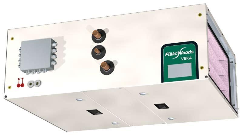
6 Installation, Connection Installation procedure Process unit VEKA Control Unit is mounted on the VEKA air handling unit side. If voltages higher than AC 29 V (e.g. AC 240 V) are connected to the low-voltage terminal blocks by mistake, the entire apparatus will be destroyed. The electrical connection must take place in the following order: First connect all peripheral equipment and then the supply voltage. Fläkt Woods 8592 GB Subject to alteration.

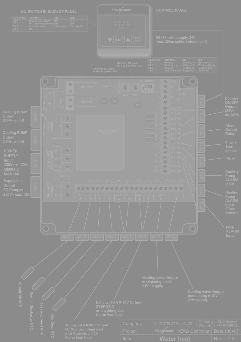
7 Installation, Connection Connection instruction Terminal blocks DIL Switch in back of panel DIL SWITCH CONTROL ON OFF DIL 1 Buzzer when alarm ON OFF DIL 2 Buzzer when warning ON OFF DIL 3 Input AI config. Filter switch Start enable DIL 4 Always OFF CONTROL PANEL RS485 with supply 24V DIL SWITCH CONTROL ON OFF DIL 1 Heating Heating ON Heating OFF Minimum DC output for Cooling Valve Minimum DC output for Heating Valve DIL 2 Heating type Water coil Electrical heater DIL 3 Cooling Cooling ON Cooling OFF DIL 4 Control method Supply air Room air Heating Pump Output 230V - on/off Cooling Pump Output 230V - on/off Power Supply Input 230Vac +/- 20% 50/60 Hz Max 16A Supply fan Output FC Compac 230Vac max 13A Damper ON/OFF Output (24 Vac on AO4) Alarm Output Relay Filter / Start enable Timer Cooling Pump ALARM Input Heating Pump ALARM Input (Flow switch) FIRE ALARM Input Supply air NTC Room / Discharge NTC Freeze protect NTC Outdoor NTC Supply FAN 0-10V Output FC Compac integrated with Auto stop <2V Alarm Feed back Exhaust Fan 0-10V Output Step Box or anything else Alarm feed back Heating valve Output modulating 0-10V 24V-supply Cooling valve Output modulating 0-10V 24V-supply Fläkt Woods 8592 GB Subject to alteration.
8 Installation, Connection Controller - IO Function IO Type Connection Relay outputs Relay 1 C-pump or electric air heater Digital Pin 1,2 Relay 2 C-pump cooling Digital Pin 3,4 DO1 Alarm output Digital Pin 42, 43 DO2 Damper output Digital Pin 44, 45, 34 (24VAC) DO3 Running indication Digital Pin 46, 47 Analogue outputs AO1 Control signal supply fan Analogue (0-10 V) Pin 21, 22 AO2 Control signal exhaust fan Analogue (0-10 V) Pin 25, 26 AO3 Control signal heating Analogue (0-10 V) Pin 29, 30, 31 (24VAC) AO4 Control signal Cooling Analogue (0-10 V) Pin 32, 33, 34 (24VAC) Binary inputs DI1 Alarm supply fan Digital Pin 23, 24 DI2 Alarm exhaust fan Digital Pin 27, 28 DI3 C-pump or electric air heater Digital Pin 38, 35 DI4 C-pump cooling Digital Pin 39, 35 AI1 Fire or smoke alarm Analogue Pin 37, 36 AI2 Timer Analogue Pin 40, 36 AI3 Filter / Start enable Analogue Pin 41, 48 Temperature inputs TEMP 1 Temperature supply air NTC Pin 13, 14 TEMP 2 Temperature room/discharge air NTC Pin 15, 16 TEMP 3 Freeze protection sensor NTC Pin 17, 18 TEMP 4 Temperature out door NTC Pin 19, 20 RS485 RS 485 IO Operation panel Digital 48, 49, 50, 51, 52, 53 DIL-switch Control unit (RC1) ON-position OFF-position DIL 1 Heating Heating ON Heating OFF DIL 2 Heating type Water coil Electric heater DIL 3 Cooling Cooling ON Cooling OFF DIL 4 Control method Supply air temperature Room / discharge air temperature- DIL-switch Operation panel (OP) ON-position OFF-position DIL 1 Buzzer when ALARM ON OFF DIL 2 Buzzer when WARNING ON OFF DIL 3 Input AI3 configuration Filter switch Start enable DIL 4 Always OFF Note Set DIL switches on control unit and operating panel according to system application. Fläkt Woods 8592 GB Subject to alteration.
9 Installation, Connection Connection instruction Fläkt Woods 8592 GB Subject to alteration.
10 Installation, Connection Fläkt Woods 8592 GB Subject to alteration.
11 Installation, Connection Fläkt Woods 8592 GB Subject to alteration.
12 Installation, Connection Action in the event of a fault In the event of a fault in VEKA Integrated control, the following checks must be carried out: Power supply 230 V AC Correct connection of the terminal blocks Correct connection of the peripheral units Fault diagnostics with the aid of blinking red LEDs inside the control unit If the fault cannot be rectified using these measures, the apparatus must be replaced and returned (via the supplier) to the factory. Note See also chapter 3, Alarm guide and Frequently asked questions for a description of the alarm messages and other faults. Fläkt Woods 8592 GB Subject to alteration.
13 Operation Operation panel Manöverelement Funktion 1 LCD-display Visar värden och inställningar 2 EXIT-knapp Backar en meny 3 Radväljarknappar Navigering på menyn och mellan parametrar/inställt värde (+/ ) 4 SET-knapp Bekräftar ändring (inställning) av värden och menyalternativ Menu system Levels Access to data is hierarchically divided between two levels: Operating level Configuration level Operating level At operating level, the end user can read and alter current statuses, reference values and time programs without having to specify a password. Configuration level By entering an approved password, access is gained to the configuration level, where it is possible to read and alter all values that are accessible at both configuration and operating level. The parameter names are followed by values that can be read and altered. Password The password function protects against access to data and comprises four digits that can be altered if necessary. Predefined password The predefined password to access the configuration level is: 0000 User-defined password After accessing the configuration level, the user can alter the password by selecting Change password. Password is active 15 minutes. If the factory-set password is altered, it is important to remember the new password as the factory-set password is no longer present. To reset the password, a higher password is required. Contact the supplier. Menus One parameter and the value are shown on one page. Fläkt Woods 8592 GB Subject to alteration.
14 Operation Overview menu tree Welcome level 1st level 2nd level 3rd level :24 STATUS Actions here M Operation M1 Setpoints M2 Min/max supply team M3 Service switch M4 Type of control M5 Actual value M6 SupplyAirTemp M7 RoomAirTemp M8 FreezeGuardTemp M9 Outdoor Air Temp M10 Cooling M11 Heating PARAMETERS Operating level S Scheduler S1 Daytime scheduler S2 Weektime scheduler Configuration level P Log in Give password **** P2 Fan speed P3 Frost protection P4 Alarm output P5 Temp Alarm P6 Alarm class P7 Service alarm time P8 Pump function P9 Timer P10 Summar/winter comp. P11 Controller tuning P12 Directing of inputs P13 Change password P14 Real clock/date P15 Factory settings P16 Preheat Fläkt Woods 8592 GB Subject to alteration.
15 Operation Navigate You can see from page code where in menu tree you are. First level is identified with a letter. Second and third level is identified with a number. Navigate in the same level with arrow buttons. Go to the next level with SET button Come back to the higher level with EXIT button. Activate parameter value change with SET button. Change parameter value with arrow buttons. Example Enter password (factory setting 0000) and setting for current date and time. Log In P Give Password 0**** P1 Fan speed P2 Real clock/date P14 Set clock P When you are on the basic view, press SET. Then press arrow down so that the cursor is on Log in line 2 Press SET again to display the first figure (0). Specify the first figure for the code with the arrow buttons and confirm with SET. Specify the remaining three figures in the same way. When the last figure has been confirmed with SET, the cursor goes to the P2 Fan speed page. 3 Using the arrow buttons go to the Real clock/date page P14. 4 Select first P14.1 Set clock using SET button. Select right time with arrow buttons and press SET button. Set date P Press Exit button and you can select Set date with arrow button. You can set right date, month, year and weekday with the same way. Fläkt Woods 8592 GB Subject to alteration.
16 Operation Alarm management In the event of alarms or incorrect operation, alarm text appears on display. Also buzzer sound can be heard from HMI, if this function is selected from HMI DIL switches (see table 2.2.1). Alarm can be acknowledged from EXIT button after cause of alarm is fixed. Alarms can be configured as A or B alarms where A has higher priority and B has lower. Alarms have fixed delays. Differences The following differences exist between the two alarm types: Alarm guide Below are possible alarm messages and proposed actions/causes. Read off the alarm on the display. Check the connection on the terminal block. Check the component from where the alarm originates. Check the connection to the component. Check the contact function for the digital alarms in the regulator, compare with diagrams and components. Check the parameter setting. Priority A The plant is disconnected Must be acknowledged manually. The plant is then connected again. Priority B Only alarm indication The alarm must not to be acknowledged manually. Alarm guide Alarm Cause Action Temperaturgivarfel The sensor is not connected. Check the sensor s connection against the wiring diagram. The sensor is connected in the wrong position. Check the sensor s connection against the wiring diagram. Open-circuit in the measuring circuit. Check for an open-circuit in the sensor cable. Short-circuit in the measuring circuit. Check for a short-circuit in the sensor cable. Incorrect type of sensor connected. Check that the sensor is type NTC thermistor. Alarm freeze guard Water temperature too low. Return water temperature may not drop below the set value. Check that hot water is reaching the unit. Check that the circulation pump is in operation. Check that the heater valve has a signal and is working. Check that the heater battery is intact and not leaking. Fire alarm Incorrect contact function at alarm input. The fire alarm input is configured NC (Normally closed), change to NO (Normally open). Alarm electric battery/pump The electric battery is not correctly connected. Incorrect contact function at alarm input. Check the electric battery s connection against the wiring diagram. If the input is configured NO, configure as NC. Alarm cooling battery Incorrect contact function at alarm input. If the input is configured NC, configure as NO. Fläkt Woods 8592 GB Subject to alteration.
17 Operation Alarm Cause Action Alarm filter guard The filter guard is incorrectly connected. Check the filter guard s connection against the wiring diagram and check the pressure connectors and the alarm limit. Incorrect contact function at alarm input. If the input is configured NO, change connection to NO in the filter guard. The filters are dirty. Replace the filters! Alarm fan The fans are stationary. Check whether the automatic fuses have tripped. Reset if necessary. If the fuses have not tripped, switch off the power to the unit, wait a while and switch on again. Check airflow in the supply fan. Service alarm The unit s operating time has exceeded When service alarm comes on, it buzzes (if selected from the set alarm limit. DIL -switch 2) and indicates on display. Press Exit and it goes of Alarm comes again after 24 hours To reset and start another time period (1 12 months), press arrow UP AND arrow DOWN for 5 seconds. Tips! Larmgränsen kan användas för att beställa service, t.ex. filterbyte. Frequently asked questions (FAQ) The display How can the text be changed to English in the display? There are separate program for different languages. Display need to be ordered with right language. Why unit stops when disconnecting display? Controller program runs in display microprocessor. It needs always to be connected. Temperature The regulator cannot maintain the desired. temperature. What might be wrong? Is the heater battery/cooling battery designed for the prevailing temperature? Investigate whether the water temperatures to the batteries are sufficiently high/low. Investigate whether the electric battery is receiving power. Make sure that no windows or doors are open. Why does the relevant temperature reference value deviate from the values that are set under the reference values? The Summer/Winter compensation function may be activated. This compensation moves the reference value depending on the prevailing ambient temperature. Heating / Cooling The Display shows Alarm Heat Pump although the unit has electric heating. Is the unit incorrectly configured? The alarm text refers to overheating of the electric battery or a circulation pump alarm. The electric heater trips the automatic overheating protection. How is the fault rectified? The air supply temperature is too high. Decrease the reference value or increase the flow; alternatively decrease the parameters for Max. control signal heating under the menu: M2.2 Maximum temp Fläkt Woods 8592 GB Subject to alteration.
18 Operation Värmning/Kylning The unit is switched off but the pump for the heater battery is running. Is something wrong? In the event of low return water temperatures from the battery, the freeze guard function operates the heater battery pump to ensure there is no risk of the battery freezing when the unit starts. The pump is operated every Monday at 12:00 or is set to constant operation. The pump operates constantly at low ambient temperatures. The unit is switched off but the pump for the cooler battery is running. Is something wrong? The pump is operated every Monday at 12:00 or is set to constant operation. Why does the electric battery not produce any heat, even though the control signal is 100%? The parameter for Max. control signal heating may be set at a low level. There is no power supply / operating signal to the electric battery. The overheating protection may have tripped. Why does the unit stop when the external timer is activated? The control inputs can be configured for different functions, for example as external stop, see under menu: P9.1 Timer function. Why the unit won t start although time program should start it? If DIL switch 3 in operation panel is OFF and there is no jumper between terminals AI3 and +VCCOUT, the unit won t start. Change DIL switch position to ON (filter switch) or connect the jumper. AI3 is configured permanently NC with external stop. Miscellaneous Filter alarms are received despite the fact that there is no filter guard. What is wrong? DIL switch 3 in operation panel configures input AI3 as start enable or filter switch. Operation How do I set the time program so that the unit is switched off at weekends? Use the Week program function and set the unit to be switched off between Saturday morning and Sunday evening; also remember to Activate switching. Fläkt Woods 8592 GB Subject to alteration.
19 Control principle Supply air temperature control If supply air temperature control is selected, controller keeps supply air temperature GT1 in set point by controlling the heating valve SV1 or electric heater SK1 and cooling valve SV2. Supply air temperature control Supply air temperature controller Set point for heating and cooling SV1 SV2 Supply air temperature GT1 Heating and cooling has separate set points. Cooling set point can t be lower than heating set point. PI Controller has separate tuning parameters for heating and cooling. Room or exhaust air temperature control If room or exhaust air temperature control is selected, controller keeps room or exhaust air temperature GT2 (GT12) in set point. Room or exhaust air temperature controller output is set point for supply air temperature controller. This controls valve heating valve SV1 or electric heater SK1 and cooling valve SV2. Also supply air temperature should be within certain limits. Fläkt Woods 8592 GB Subject to alteration.
20 Reglerprincip Room / exhaust air supply air cascade control with fixed supply air temperature reduction Set points for heating and cooling Room air temperature controller Supply air temp. controller SV1 SV2 GT2 (GT12) Room / exhaust air temperature sensor Supply air temp. GT1 Min/max limits Supply air temperature sensor Return water control Heating coil return water temperature GT5 is prevented to drop under the limit value (reference value for min. operating temperature) by controlling the valve SV1. This controller output has higher priority than air temperature controllers. Fläkt Woods 8592 GB Subject to alteration.
21 of the operating level Welcome page At the welcome page you can see current date (dd. mm.yyyy) and time (hh.mm). Also status of VEKA unit is seen on this page. If you press EXIT button, you can see the version of the program. Display returns to this page automatically if no button has pressed during three minutes. Operation Welcome ÿ Operation (M) At the operation you can change set points, monitor control signals and temperatures Set points Service switch Welcome ÿ Operation (M) ÿ Service switch (M3) This page indicates is timer function activated or not. Automatic -mode indicates that unit is controlled by time program. Manual -mode indicates that timer function has started the unit. Stopped - mode indicates that timer function has stopped the unit or Start Enable in not active. Type of control Welcome ÿ Operation (M) ÿ Type of control (M4) This page indicates the type of control: supply air temperature or room/exhaust air temperature control. Selected from the control unit DIL switch 4 (see page 7). Welcome ÿ Operation (M) ÿ Set points (M1) At the set point you can change set points for heating (M1.1) and cooling (M1.2). Temperature range in set point is between C. Set point for heating should be lower than set point for cooling. Min / Max supply air temperature during cascade control Welcome ÿ Operation (M) ÿ Min/Max Supply TF (M2) Display and setting of Min and Max temperature for the supply air sensor. This is used with room/exhaust air temperature control so that supply air temperature don t exceed limit values. Temperature range in set point is between C. Actual set point Welcome ÿ Operation (M) ÿ Actual setpoint (M5) This page indicates calculated set point for temperature controller. Set point for heating and cooling alternates on display every 4 seconds. Summer and winter compensation affects to the calculation if it is activated. Supply air temperature Welcome ÿ Operation (M) ÿ Supply temp (M6) This page indicates supply air temperature. It s also indicated if no sensor is connected or if there is sensor failure. Fläkt Woods 8592 GB Subject to alteration.
22 of the operating level Room/Exhaust air temperature Heating output Welcome ÿ Operation (M) ÿ Room temp (M7) This page indicates room/exhaust air temperature. It s also indicated if no sensor is connected or if there is sensor failure. Welcome ÿ Operation (M) ÿ Heating output (M11) This page indicates control signal 0 100% (0 10V) for cooling valve. Minimum voltage can be adjusted from SET 1 trimmer on control unit. Freeze guard temperature Welcome ÿ Operation (M) ÿ Freeze guard temp (M8) This page indicates freeze guard temperature. It s also indicated if no sensor is connected or if there is sensor failure. Time control program VEKA integrated controller is equipped with a time control program with four independent switching times per day that apply to all days (day program) and two possible exceptions from the day program per week (week program). Outdoor temperature Welcome ÿ Operation (M) ÿ Outdoor temp (M9) This page indicates outdoor temperature. It s also indicated if no sensor is connected or if there is sensor failure. Cooling output Welcome ÿ Operation (M) ÿ Cooling output (M10) This page indicates control signal 0 100% (0 10V) for cooling valve. Minimum voltage can be adjusted from SET 2 trimmer on control unit. Day program Welcome ÿ Scheduler (S) ÿ Daytime schedul (S1) The day program can handle four independent switching times per day. Time and fan speed are set for each switch. Example Example of a possible setting of a day program with a 2-speed fan: Switching time Switching time Action D1 (S1.1) 08:00 Low speed (S1.2) D2 (S1.3) 12:00 High speed (S1.4) D3 (S1.5) 17:00 System stop (S1.6) D4 (S1.7) 00:00 Non Active (S1.8) Fläkt Woods 8592 GB Subject to alteration.
23 of the operating level Note The day program applies to all weekdays, and the times that are used for most days are set here. On the row Week program, however, two exceptions from the day program can be entered, such as different times for the weekend. When making the setting, note that action Non Active means NO activity at specific switch time. Week program Welcome ÿ Scheduler (S) ÿ Weektime schedul (S2) The week program is used for two optional exceptions from the day program. The day program is active until the starting time for the week program and is reactivated immediately after the closing time for the week program. Example Example of a possible setting of a week program with a 2-speed fan: Switching Conn- Time Disconn- Time Action alternative ection on ection off day day W1 Sat Sat Low speed (S2.1) (S2.2) (S2.3) (S2.4) (S2.5) W2 Sun Sun Low speed (S2.1) (S2.6) (S2.7) (S2.8) (S2.9) (S2.10) When making the setting, note that action Non Active means NO activity at specific switch time. Fläkt Woods 8592 GB Subject to alteration.
24 of configuration level Configuration level is displayed after logging in. Fan speed Both supply and exhaust fan speed can be set stepless from operating panel. Fan compensation Welcome ÿ Fan speed (P2) ÿ Fan Compensation (P2.5) Blocking of HIGH speed when ambient temperature is higher than Block High Speed setting. Supply fan low Welcome ÿ Fan speed (P2) ÿ Supply fan low (P2.1) Supply fan low speed can be set between 0 100%. This means 2 10V signal to frequency converter. Supply fan high Welcome ÿ Fan speed (P2) ÿ Supply fan high (P2.2) Supply fan high speed can be set between 0 100%. This means 2 10V signal to frequency converter. Exhaust fan low Welcome ÿ Fan speed (P2) ÿ Exhaust fan low (P2.3) Exhaust fan low speed can be set between 0 100%. This means 2 10V signal to frequency converter. Exhaust fan high Welcome ÿ Fan speed (P2) ÿ Exhaust fan high (P2.4) Exhaust fan high speed can be set between 0 100%. This means 2 10V signal to frequency converter. Block High Speed Welcome ÿ Fan speed (P2) ÿ Block high speed (P2.6) Setting for ambient temperature limit. Frost protection When VEKA is fitted with water coil, frost protection function prevents water coil from freezing. Ref min operation Welcome ÿ Frost protection (P3) ÿ Ref min operation (P3.1) Water coil temperature is normally controlled from Supply or Room air controller. But if the frost sensor measures lower temp than this setting, the output of the frost PI controller takes over. Reference value for keeping warm Welcome ÿ Frost protection (P3) ÿ Ref keeping war (P3.2) When VEKA is with water coil AND stopped, the coil temperature is maintained at this level to prevent freezing. Fläkt Woods 8592 GB Subject to alteration.
25 of configuration level Reference value for freeze guard alarm Deviation temperature Welcome ÿ Frost protection (P3) ÿ Ref freeze guard (P3.3) If the temperature is below the adjustable freeze limit, an A alarm is obtained, which also stops the unit. Welcome ÿ Temp alarm (P5) ÿ Deviation temp (P5.1) Setting of common alarm limit for temperature alarm, i.e. if controlled temperature exceeds this set value for longer than 60 min, an alarm is generated. Alarm output The alarm outputs for the two parameters Alarm priority A and Alarm priority B are used for monitoring the operation of the entire plant. In this way, individual alarms are co-ordinated as a combined alarm, which is indicated as an alarm with either priority A or B. The combined alarm indicates that there is a fault in the plant, but not what the fault it. To ascertain this it is necessary to look in the alarm list. Parameter for selecting whether only A alarms or both A and B alarms are to be indicated. Relay function Welcome ÿ Alarm Output (P4) ÿ Relay function (P4.1) Class A or class A+B alarms will activate the relay if selected. Temperature alarm Settings for temperature deviation from reference values. Block Alarm summer Welcome ÿ Temp alarm (P5) ÿ Block al. summer (P5.2) When activating this parameter, the temperature alarm is blocked during the summer. Summer in this context refers to when the ambient temperature exceeds 15 C. Alarm class Some alarms can be configured as A or B alarms where A has the higher priority and B lower. Alarms have fixed delays. Following alarms have fixed alarm class A: Frost protect, delay 1 sec. Supply fan, delay 1 sec. Fire and smoke, delay 1 sec. Heating pump / Electrical heater, delay 1 sec. Communication error with controller and display, delay 10 sec. Alarm cooling Welcome ÿ Alarm class (P6) ÿ Alarm cooling (P6.1) Cooling pump alarm. Class B as default. Delay 1 sec. Fläkt Woods 8592 GB Subject to alteration.
26 of configuration level Alarm exhaust fan Alarm return water temperature sensor Welcome ÿ Alarm class (P6) ÿ Alarm exh. fan (P6.2) Exhaust fan alarm. Class B as default. Delay 1 sec. Welcome ÿ Alarm class (P6) ÿ Alarm water sensor (P6.7) Defective sensor. Class A as default. Delay 1 sec. Alarm temperature Alarm filter Welcome ÿ Alarm class (P6) ÿ Alarm temperature (P6.3) Controlled temperature deviation alarm. Class B as default. Delay 60 min Alarm service Welcome ÿ Alarm class (P6) ÿ Alarm service (P6.4) Operating time alarm. Class B as default. Alarm supply air temperature sensor Welcome ÿ Alarm class (P6) ÿ Alarm supp. sensor (P6.5) Defective sensor. Class A as default. Delay 1 sec. Welcome ÿ Alarm class (P6) ÿ Alarm water sensor (P6.8) Dirty filter. Class B as default. Delay 30 sec. Service alarm time Service alarm when the unit has exceeded the set operating time. This can be used for example filter change alarm. Alarm delay Welcome ÿ Service alarm time (P7) ÿ Alarm delay ser. Service (P7.1) Alarm delay can be set between 1 12 month or off. Alarm room / exhaust air temperature sensor Welcome ÿ Alarm class (P6) ÿ Alarm exh. sensor (P6.6) Defective sensor. Class A as default. Delay 1 sec. Pump function The circulation pump for the heating circuit is controlled so that it is in operation at low ambient temperature (12 C) and when the output signal to the heater valve > 0 V. The circulation pump for the cooling circuits is controlled so that it is in operation when cooling is required. Fläkt Woods 8592 GB Subject to alteration.
27 of configuration level Cooling pump motion Welcome ÿ Pump function (P8) ÿ Cool pump motion (P8.1) Activates movement of the pump for the cooling circuit to prevent the pump seizing. The movement takes place every Monday at 12:00. The pump can also be set in continuous operation. Heating pump motion Welcome ÿ Pump function (P8) ÿ Heat pump motion (P8.2) Activates movement of the circulation pump for the heating circuit to prevent the pump seizing. The movement takes place every Monday at 12:00. The pump can also be set in continuous operation. Timer Parameters for setting function method for the timer input. Timer function Welcome ÿ Timer (P9) ÿ Timer function (P9.1) Function method when timer input is activated: Low speed, high speed or external stop. External stop don t prevent airing of the electric battery. Timer period Welcome ÿ Timer (P9) ÿ Timer period (P9.2) Note This parameter has no function in the event of electric heating. When a push-button is used for extended operation, the desired operating time is set using this parameter. Min operation time for pumps Welcome ÿ Pump function (P8) ÿ Min oper. pumps (P8.3) Parameter for setting the minimum operating time for both the cooling pump and the circulation pump for the heating circuit. Fläkt Woods 8592 GB Subject to alteration.
28 of configuration level Summer Winter compensation Summer/winter compensation is used for automatic switching of the plant between summer and winter operation. With this, the basic reference value is moved as a function of the ambient temperature. Function diagram Stop point summer compensation Welcome ÿ Summer/Wint comp (P10) ÿ Summer stop point (P10.2) End temperature at E S at which the basic reference value has been displaced by 100% (in relation to the total displacement delta). Delta summer compensation Welcome ÿ Summer/Wint comp (P10) ÿ Summer delta (P10.3) Max. displacement of the basic reference value (total displacement). Explanation F S E S Starting point for summer compensation End point for summer compensation Starting point winter compensation S S Delta (total displacement) in K at end point E S F W Startpunkt för vinterkompensering E W Slutpunkt för vinterkompensering S W Delta (total förskjutning) i K vid slutpunkt EW T A Omgivningstemperatur w Referensvärdesändring conditions Delta not equal to 0.0 applies for activation of summer/winter compensation Starting point summer compensation Welcome ÿ Summer/Wint comp (P10) ÿ Summer start point (P10.1) Welcome ÿ Summer/Wint comp (P10) ÿ Winter start point (P10.4) Starting temperature at FW at which the basic reference value starts to be displaced (proportional with the falling ambient temperature). Stop point winter compensation Welcome ÿ Summer/Wint comp (P10) ÿ Winter stop point (P10.5) End temperature at EW at which the basic reference value has been displaced by 100% (in relation to the total displacement delta). Starting temperature at FS at which the basic reference value starts to be displaced (proportional with the rising ambient temperature). Fläkt Woods 8592 GB Subject to alteration.
29 of configuration level Delta winter compensation Cooling regulator KP Welcome ÿ Summer/Wint comp (P10) ÿ Vinter delta (P10.6) Max. displacement of the basic reference value (total displacement). Regulator settings The regulator is adapted to the control object with the following parameters: Reinforcing factor KP I-time TN The control effect is optional: P or PI. The relationship between KP and P-bands is as follows: P-band = 100/KP Unit: TN in seconds; (the units are not displayed on HMI) Heating regulator KP Welcome ÿ Controller tune (P11) ÿ Heat Control KP (P11.1) Reinforcing factor KP for heating regulator. Heating regulator TN Welcome ÿ Controller tune (P11) ÿ Heat Control TN (P11.2) I-time TN for heating regulator. Welcome ÿ Controller tune (P11) ÿ Cool Control KP (P11.3) Reinforcing factor KP for cooling regulator. Cooling regulator TN Welcome ÿ Controller tune (P11) ÿ Cool Control TN (P11.4) I-time TN for cooling regulator. Freeze guard regulator KP Welcome ÿ Controller tune (P11) ÿ Freeze Control KP (P11.5) Reinforcing factor KP for Freeze guard regulator. Freeze guard regulator TN Welcome ÿ Controller tune (P11) ÿ Freeze Control TN (P11.6) I-time TN for Freeze guard regulator. Room/exhaust air temperature regulator KP Welcome ÿ Controller tune (P11) ÿ Room Control KP (P11.7) Reinforcing factor KP for room/exhaust air temperature regulator. Fläkt Woods 8592 GB Subject to alteration.
30 of configuration level Room/exhaust air temperature regulator TN Welcome ÿ Controller tune (P11) ÿ Room Control TN (P11.8) I-time TN for room/exhaust air temperature regulator. Setting contact function for alarm inputs Welcome ÿ Directing inputs (P12) Selection regarding an alarm input must be of the type closing (NO) or opening (NC). Fire and smoke alarm Welcome ÿ Directing inputs (P12) ÿ Fire smoke alarm (P12.1) NO (Normally Open) The contact is open in the rest position and closes in the event of an alarm. NC (Normally Closed) The contact is closed in the rest position and opens in the event of an alarm. Fire and smoke alarm input is configured normally closed at the factory. Heating pump / Electrical heater alarm Cooling alarm Welcome ÿ Directing inputs (P12) ÿ Alarm pump/cool (P12.3) Kyllarmsingången konfigureras som normalt öppen på fabriken. Fläktlarm Welcome ÿ Directing inputs (P12) ÿ Alarm fans (P12.4) Fläktlarmsingångarna konfigureras som normalt öppna på fabriken. Change password Welcome ÿ Change password (P13) New password Welcome ÿ Change password (P13) ÿ New password (P13.1) Changing password see Password, page 13. Set clock / date Welcome ÿ Set clock / date (P14) Here you can set time and date. Welcome ÿ Directing inputs (P12) ÿ Alarm pump/heat (P12.2) Heating pump / Electrical heater alarm input is configured normally open at the factory. Fläkt Woods 8592 GB Subject to alteration.
31 of configuration level Set clock Welcome ÿ Set clock / date (P14) ÿ Set clock (P14.1) Set right time Note Switching between summer and wintertime need to be done manually. Set day of the week Welcome ÿ Set clock / date (P14) ÿ Set week day (P14.5) Set right day of the week. Factory settings Set date Welcome ÿ Set clock / date (P14) ÿ Set date (P14.2) Set right date. Set month Welcome ÿ Set clock / date (P14) ÿ Set month (P14.3) Set right month. Set year Welcome ÿ Set clock / date (P14) ÿ Set year (P14.4) Set right year. Welcome ÿ Factory settings (P15) Reset to default Welcome ÿ Fabriksinställ (P15) ÿ Reset to default (P15.1) When you want to get factory settings back change parameter value to YES and hold SET for 10 seconds. Preheating Welcome ÿ Preheating (P16) Effekt Water-heated air heaters are sensitive to frost. If the air conditioning unit is disconnected at night and there are low ambient temperatures at start-up, the sudden supply of cold outdoor air would cause the water in the pipes to freeze. This problem is particularly tangible in conjunction with 2-position dampers. In order to circumvent this, the water circuit is preheated with hot water before the outdoor air damper is opened. At start-up, only the air heater s heating circuit pump starts and the heating valve opens prevailing ambient temperature for an adjustable period of time. The risk of freezing damage is eliminated, and the unit then switches to normal control. Fläkt Woods 8592 GB Subject to alteration.
32 of configuration level conditions The pump in the heating circuit is connected The valve opens depending on the preheating... temperature. Ambient temperature sensor connected Preheating time > 0.0 s (P16.1) Ambient temperature < setting in parameter.. (P16.2) Preheating period Welcome ÿ Preheating (P16) ÿ Preheating period (P16.1) Set the preheating time. Preheating ambient temperature limit Welcome ÿ Preheating (P16) ÿ Preheating temp (P16.2) Set the preheating ambient temperature limit. Below this limit value preheating is active Fläkt Woods 8592 GB Subject to alteration.

33 Parameter list Overview of operating level Fläkt Woods 8592 GB Subject to alteration.

34 Parameter list Overview of configuration level Fläkt Woods 8592 GB Subject to alteration.

35 Parameter list Fläkt Woods 8592 GB Subject to alteration.
36
Instructions for the fan motor control system with integrated wiring terminals SILVER C
 Instructions for the fan motor control system with integrated wiring terminals SILVER C 1. General The motor control system is used for controlling the type EC, 0.41-10 kw fan motors in the SILVER C units.
SIRe Competent Air Curtains Water With quick guide. SIReAC. For wiring diagram, please see p Original instructions
 Original instructions SIRe Competent Air Curtains Water With quick guide SIReAC SE... 2 GB... 19 DE... 36 FR... 54 For wiring diagram, please see p.71-73 For more languages, please see www.frico.se SIRe
Air handling unit STING Manual Section B Control equipment Assembly and Installation. September Fläkt
 Air handling unit STING Manual Section B Control equipment Assembly and Installation September 2008 Fläkt Contents (STING Manual Section B) Electrical cabinet 10-50...3 Electrical connection and fuse protection
Instructions for the fan motor control system, SILVER C
 Instructions for the fan motor control system, SILVER C 1. General The motor control system is used for controlling the type EC, 0.41-10 kw fan motors in the SILVER C units. The motor control system is
ER65-DRW Controller. Heating Applications. Product Bulletin. Heating Controller
 PB_ER65-DRW_ 202 ER65-DRW Controller Heating Applications Product Bulletin The controller is a digital device for domestic or residential heating units. It covers water and air heating applications. All-in-one
C User manual
 C10...40 User manual Introduction COORIGO is a completely new range of controllers which has been designed to be easy to use and operate. The controllers have a display and built in panels for operation
CLEVER CONTROL Version: V3
 CLEVER CONTROL Version: V3 INSTALLATION AND FUNCTIONING MANUAL USER AND BASIC VERSION Please, read these instructions carefully before attempting installation SECURITY ADVISE SIMBOLS Attention, Danger,
OPERATION AND MAINTENANCE MANUAL
 OPERATION AND MAINTENANCE MANUAL Prg Sel line alarm on on/off alarm enter Clear EMIpro MICROPROCESSOR CONTENTS 1 GENERAL CHARACTERISTICS Page 2 1.1 General description Page 2 2 EMIPRO USER INTERFACE Page
Manual for the integration in BMS/GTC
 Manual for the integration in BMS/GTC Communication parameters MODBUS RTU and BACNET COMMUNICATION UTBS PRO-REG Software Version 3.6 EN ÍNDEX 1. GENERALITIES...2 1.1. Introduction...2 1.2. signals types...2
Modbus TCP Register List GreenManager for GreenMaster C-F Valid for firmware version 2.0 or later
 Modbus TCP Register List GreenManager for GreenMaster C-F Valid for firmware version 2.0 or later Overview Modbus can access single adresses or multiple addresses simultaneously; either reading or writing
AUS. Devireg TM 535 Installation and user manual
 AUS Devireg TM 535 Installation and user manual 1 Congratulations with... your DEVI floor heating system Your property has been installed with a DEVI heating system. DEVI is Europe s leading floor heating
SAUTER flexotron 800 Ventilation application User Guide
 SAUTER flexotron 800 Ventilation application User Guide P100012091 1 Table of content P100012091 2 Table of content Table of content Table of content... 2 1 About this user guide... 4 2 About flexotron
Rectifier RC-series. Manual RC-series English MA doc. Manual Wall and 19 English
 Rectifier RC-series Manual RC-series English Manual Wall and 19 English Presentation The RC-series is a rectifier for either directly powering the load or for use together with batteries. It is designed
Rooftop Thermostat Controller Specification and Installation Instructions. Model TRT2422
 ºF / º C Rooftop Thermostat Controller Model TRT2422 Description The TRT2422 is a combination controller and thermostat with a built-in scheduler, which is designed for simple and accurate control of single
User s Manual. TIGER S EYE E-Series Mark V Jockey. TIGERFLOW Systems, Inc Mint Way Dallas, Texas
 User s Manual TIGER S EYE E-Series Mark V Jockey TIGERFLOW Systems, Inc. 4034 Mint Way Dallas, Texas 75237 214-337-8780 www.tigerflow.com TABLE OF CONTENTS Introduction... 4 Sequence of Operation... 5
SIRe Advanced Air Curtains Electric With quick guide. SIReAA GB DE FR For wiring diagram, please see last pages. ES
 Original instructions SIRe Advanced Air Curtains Electric With quick guide SIReAA SE... 2 GB... 22 DE... 42 FR... 62 ES... 82 IT... 102 NL... 122 NO... 142 PL... 162 RU... 181 For wiring diagram, please
Installation Instructions / User s Manual TSTAT0406 and TSTAT0408
 997-060180-5 Installation Instructions / User s Manual TSTAT0406 and TSTAT0408 4 HEAT 2 COOL DUAL FUEL TSTAT0406 & TSTAT0408-4 WIRE CAPABLE THERMOSTAT (NAXA00201DB Daughter Board sold separately) LEFT
ProCon 16, 31, 47 & 75. RVA 63 Boiler and Circuit Controller Commissioning Data.
 ProCon 16, 31, 47 & 75. RVA 63 Boiler and Circuit Controller Commissioning Data. The RVA63 controller can be utilized to control the following system configurations via LPB communication. Equipment Required
N M AirControl AHU. Control manual
 N 10.63 M 03-2016 AirControl AHU Control manual EN CONTENTS PAGE 1 - MONITORING AND CONTROL 2 1.1 The program 2 1.2 The HMI terminal 2 1.3 The controller 4 1.4 Description of the air handling units 4
Mounting and Operating Instructions EB 5610 EN. TROVIS 5600 Automation System TROVIS 5610 Heating and District Heating Controller
 TROVIS 5600 Automation System TROVIS 5610 Heating and District Heating Controller Mounting and Operating Instructions Electronics from SAMSON EB 5610 EN Firmware version 1.40 Edition December 2014 Controller
1 DOCUMENT REVISION CONTROL ELEMENTS... 9
 CONTENTS Contents 1 DOCUMENT REVISION... 8 2 SOFTWARE VERSION... 8 3 BASIC DESCRIPTION... 8 4 CONTROL ELEMENTS... 9 4.1 BASIC DISPLAYS...10 4.2 CONTROL KEYS...11 4.2.1 Rotary button (Press / Turn)...11
Condensing Boiler RS100 Controller Training Program
 Condensing Boiler RS100 Controller Training Program Training Program #501102A 062311 www.rinnai.us 2009 Rinnai America Corporation Features and Benefits The RS100 connects directly to the boiler and acts
C-series Controllers for air handling systems
 C-series Controllers for air handling systems Corrigo, C-series, is a range of digital controllers for air-handling systems designed to be easy to use and operate, having a large capacity, and a high degree
MODBUS RS485. » Technical instructions. Air Comfort. Housing ventilation
 Air Comfort Air Treatment Housing ventilation MODBUS RS485» Technical instructions 2 Modbus RS485 Technical instructions Description, Connections, Presentation, decimals Description RS485 has two connections,
EKC 347 Liquid Level Controller REFRIGERATION AND AIR CONDITIONING. Manual
 EKC 347 Liquid Level Controller REFRIGERATION AND AIR CONDITIONING Manual Contents Introduction...3 Valve compatibility...3 Features...3 Application examples...3 Ordering...3 Operating the EKC 347...4-5
EBC20. Instructions for fitting, installation and operation. Read and save these instructions!
 EBC20 UK Instructions for fitting, installation and operation Read and save these instructions! 2 3002878 EBC20 UK 290415 1. Product information............................................... 4 1.1 Delivery.............................................................
EFET 535. Installation Manual INT INT
 MAKING MODERN LIVING POSSIBLE EFET 535 Installation Manual Warning! This manual is only to be used by a professional installer to install and set up the thermostat properly. It is not intended for the
EasyTronic III MANUAL SERVICE
 rev.6 EasyTronic III MANUAL SERVICE General characteristics: Power supply 24 Vac ±15% Max consumption at 24Vac 300mA Relay outputs 6 Maximum relay current 8 A res. Serial standard RS232 2 Serial standard
Capacity controller AK-PC 651
 User Guide Capacity controller AK-PC 651 ADAP-KOOL Refrigeration Control System Introduction Application The controller is used for capacity regulation of compressors and condensers in small refrigeration
Dryer Controller M720
 User Manual Dryer Controller M720 Hardware version 2.00 Software version 2.00 Manual M720 Dryer controller Page 1 of 60 Document history Preliminary version: - Created in April, 2009 Hardware Version 2.00,
REPEATER FS5200R INSTRUCTION MANUAL
 REPEATER FS5200R INSTRUCTION MANUAL Instruction Manual Page1 CONTENTS 1. Introduction... 3 2. Function... 3 3. Technical data... 3 4. Contents of delivery... 4 5. General information... 5 6. Duty Mode...
Corrigo E - User Manual Ventilation
 Corrigo E - User Manual Ventilation DISCLAIMER The information in this manual has been carefully checked and is believed to be correct. Regin however, makes no warranties as regards the contents of this
ENERGY LIGHT USER S GUIDE ENERGY LIGHT USER S GUIDE
 ENERGY LIGHT USER S GUIDE Release January 2001 CONTENTS 1.0 GENERAL CHARACTERISTICS... 4 1.1 MAIN CHARACTERIS TICS... 4 2.0 USER INTERFACE (CODE C5121230)... 5 2.1 DISPLAY... 5 2.2 MEANING OF THE LEDS...
Digital Precise Air Control - DPAC
 Digital Precise Air Control - DPAC Mode Enable Sensor Options The temperature of this sensor will determine if the unit is in heating, cooling or vent mode during Occupied operation. The following options
Capacity controller for water chiller AK-CH 650
 Capacity controller for water chiller AK-CH 650 Menu operation via AKM Menu list This menu function can be used together with system software type AKM. The description is divided up into function groups
GB-DAS. Installation and user manual DEVIreg 850 controller
 GB-DAS Installation and user manual DEVIreg 850 controller 1 Table of Contents 1: User Manual System overview......................................... 3 General use..............................................
USER'S MANUAL PU SENS 01 (A11) PU SENS 01 (A19) Sensor Control Panel
 PU SENS 01 (A19) Sensor Control Panel") USER'S MANUAL PU SENS 01 (A11) PU SENS 01 (A19) Sensor Control Panel PU SENS 01 CONTENTS Safety requirements... 3 Purpose... 4 Technical data... 4 Overall dimensions [mm]... 4 Mounting and set-up... 5
USER'S MANUAL PU SENS 01 (A11) PU SENS 01 (A19) Sensor Control Panel PU SENS 01 CONTENTS Safety requirements... 3 Purpose... 4 Technical data... 4 Overall dimensions [mm]... 4 Mounting and set-up... 5
ProCon 16, 31, 47, 75, 77 & HT. RVA 46. Zone Controller Commissioning Data.
 ProCon 16, 31, 47, 75, 77 & HT. RVA 46. Zone Controller Commissioning Data. The RVA 46 Zone Controller can only be used in conjunction with a RVA47 controlled boiler installation. The RVA46 controller
SPECIFICATIONS for AIR CONDITIONING CONTROLLER ZONE CONTROL
 SPECIFICATIONS for AIR CONDITIONING CONTROLLER ZONE CONTROL 1. INTROUCTION Zone control is a two pieces fan coil thermostat available for Heat/Cool versions. Its application is for the duct type system
User Manual. Dryer Controller M720
 User Manual Dryer Controller M720 Hardware version 1.00 Software version 1.00 Preliminary version Manual M720 Dryer controller Page 1 of 42 Document history Preliminary version: - Created in April, 2009
BLAUAIR AUTOMATIC CONTROL SYSTEM
 BLAUAIR AUTOMATIC CONTROL SYSTEM S30 (KVENT, TH-TUNE) S31 (KVENT) S32 (KVENT, PGDE) EN USER S MANUAL CONTENTS Safety requirements... 3 Purpose... 4 Technical data... 5 Installation and set-up... 6 Control...
Operating instructions
 Operating instructions Control unit - CGL Zone 0.0 C Friday 3/0/08 : 6 Wolf GmbH Postfach 380 D-84048 Mainburg Tel. +49 (0)875/74-0 Fax +49 (0)875/74600 Internet: www.wolf-heiztechnik.de Document no.:
ExactLogic BACnet Communicating Thermostat EXL01627 Sequence Datasheet Fan Coil with Modulating Fan and Heat or Cool Floating Heating and Cooling
 ExactLogic BACnet Communicating Thermostat EXL01627 Sequence Datasheet Fan Coil with Modulating Fan and Heat or Cool Floating Heating and Cooling DataSheet ev 1.12.304/4.0 June 14, 2016 Operating Sequence
VERSO-P, VERSO-R Series Air Handling Units with C3 Control System Electrical Installation and Operation Manual
 VERSO-P, VERSO-R Series Air Handling Units with C3 Control System Electrical Installation and Operation Manual EN Table of Contents 1. INSTALLATION MANUAL...3 1.1. Air Handling Units Sections Connection...3
GEYSERWISE INSTRUCTION MANUAL
 GEYSERWISE INSTRUCTION MANUAL GEYSERWISE MAX DELTA T ALL IN ONE HOT WATER MANAGEMENT Before operating and installation, carefully read all instructions. Do not discard this manual. INDEX 1. Package Contents
ggg Air Handling Unit RT 700/1000S-EC-RS INSTALLATION OPERATION & CONTROL PANEL MAINTENANCE & SERVICE
 ggg INSTALLATION DESIGN & TECHNICAL INFORMATION OPERATION & CONTROL PANEL MAINTENANCE & SERVICE Exhaust air filter, article No: Q4871 Supply air filter, article No: Q4872 June 2013 1 CONTENTS Page Installation
Installer Manual KNX Touchscreen Thermostat
 Installer Manual 02952 KNX Touchscreen Thermostat Index GENERAL FEATURES AND FUNCTIONALITY from page 5 ETS PARAMETERS AND COMMUNICATION OBJECTS from page 7 COMMUNICATION OBJECTS GENERAL FEATURES AND FUNCTIONALITY
CommStat 4. Controller for Redundant Telecom HVAC Systems PRODUCT DATA SHEET. Features and Benefits
 CommStat 4 PRODUCT DATA SHEET Controller for Redundant Telecom HVAC Systems General Description The CommStat 4 is an HVAC controller designed specifically for controlling two redundant air conditioners,
MODBUS RS485 TECHNICAL INSTRUCTIONS
 MODBUS RS485 TECHNICAL INSTRUCTIONS 2 Modbus RS485 - Technical instruction DESCRIPTION, CONNECTIONS, PRESENTATION, DECIMALS DESCRIPTION RS485 has two connections, A and B. Often there is also a protective
EUKC Cooling Unit. Compulsory declaration and recurring. The unit must NOT be used in any other way than as a cooling unit!
 Safety Precautions IMPORTANT INFORMATION! The unit must NOT be used in any other way than as a cooling unit! Carefully read, study and understand the Operation and Maintenance Instructions before you commission
Sauter flexotron 800 ventilation Manual
 Manual P100012082 Table of contents DISCLAIMER The information in this manual has been carefully checked and is believed to be correct. Fr. Sauter AG however, makes no warranties as regards the contents
Installation and Operating Manual
 Installation and Operating Manual SR868C6 System Regulator for Solar Thermal Systems Display Panel Illustration Pos. Button on display panel Button description 1 Green lamp Power indication lamp 2 On/Off
USER MANUAL. OPTIMA 312 ES960C circuit board
 USER MANUAL OPTIMA 312 ES960C circuit board TABLE OF CONTENTS 1. Installation of Optima Design... 3 1.1 Installation of the Control Panel... 3 1.2 Mounting... 3 2. Control Panel... 4 3. Installation...
Sensor Control Panel
 USER S MANUAL PU SENS 01 Sensor Control Panel V55-6EN-03(SENS).indd 1 18.08.2015 10:37:16 2 PU SENS 01 CONTENTS Safety Requirements 2 Main Technical Data 3 Control Panel Mounting 3 Control Panel Operation
AGC 200 Advanced Gen-set Controller OPERATOR S MANUAL
 Advanced Gen-set Controller OPERATOR S MANUAL Display readings Push-button functions Alarm handling Log list Document no.: 4189340607A SW version 3.5X.X or later Table of contents 1. ABOUT THIS DOCUMENT...3
REPAIR INSTRUCTIONS. TUMBLE DRYER Vented WTA34.. / WTA35..
 REPAIR INSTRUCTIONS TUMLE DRYER Vented WTA34.. / WTA35.. I. SAFETY INFORMATION Page 1 II. OPERATION Page 1 III. DESCRIPTION OF FUNCTION / TECHNICAL INFORMATION Page 2 IV. CONSUMPTION RATES / ENERGY REQUIREMENT
T-32-TS Touchscreen Thermostat. Installation Manual
 T-32-TS Touchscreen Thermostat Installation Manual TABLE OF CONTENTS Introduction...4 Getting Started...5 Installing the Thermostat...6, 8 Disassembly...6 Thermostat Location...6 Mounting the Subbase...6,
S F IT 6" / 8"HES. Quick Installation Guide. franklinwater.eu
 GB D S F IT 6" / 8"HES Quick Installation Guide franklinwater.eu Summary Page English 5-19 Deutsch 25-39 Svenska 44-60 French 63-81 Italian 84-101 GB 6" / 8"HES Quick Installation Guide franklinwater.eu
Operation and Maintenance Instructions
 Compact Air Handling Unit Operation and Maintenance Instructions Item# 415005 2015-06-23 Contents 1 Warnings...1 2 Product Description...1 2.1 Internal Components Topvex TR800-4000...1 2.2 Description
ModSync Sequencing System Installation & Operation Manual. For use with Fulton Steam Boilers.
 ModSync Sequencing System Installation & Operation Manual For use with Fulton Steam Boilers. Revision 3.0 8/21/2008 - 2 - Table of Contents Introduction Page 4 Features Page 4 Sequence of Operation Page
Operating instructions Page 14. Refrigerator Read the operating instructions before switching on for the first time
 Operating instructions Page 14 Refrigerator Read the operating instructions before switching on for the first time 7085 039-00 LKv 5710 Content Disposal notes... 14 Description of the appliance... 14 Safety
TAP v2.10 Version Date: 6/12/13. Document Microprocessor Controller for Tempered Air Products
 Document 475595 Microprocessor Controller for Tempered Air Products Reference Guide for the Microprocessor Controller Please read and save these instructions. Read carefully before attempting to operate
INSTRUCTION MANUAL REMOTE CONTROL DEVICE EASYREMOTE
 INSTRUCTION MANUAL REMOTE CONTROL DEVICE EASYREMOTE Technical features Guide to LCD symbols Guide to keys Technical features Supply by communication bus Number of temperature levels 2 (DAY / NIGHT) Temperature
Summit 3208GLD USER MANUAL. Electronics Line
 Summit 3208GLD USER MANUAL Electronics Line Table of Contents 1: Introduction... 2 2: Overview... 3 3: Keypad Functions... 4 3.1: Keypads... 4 3.2: 3108 LCD Keypad Layout... 4 4: Basic System Operation...
Operation manual. Rooftop Packaged Unit
 Operation manual Rooftop Packaged Unit odels: UATYQ20ABAY1 UATYQ25ABAY1 UATYQ30ABAY1 UATYQ45ABAY1 UATYQ50ABAY1 UATYQ55ABAY1 UATYQ65ABAY1 UATYQ75ABAY1 UATYQ90ABAY1 UATYQ110ABAY1 UATYQ115ABAY1 UATYQ20AFC2Y1
GreenCon On/Off Room Thermostat
 Description Features: Scandinavian design with white backlight; User-friendly interactive interface; Room temperature display and settings; 12 or 24 hour clock display and settings; Three-speed manual/automatic
SIRe Advanced Air Curtains Water Ambient, no heat
 Original instructions SIRe Advanced Air Curtains Water Ambient, no heat With quick guide SIReAA SE... 2 GB... 23 DE... 44 FR... 65 ES... 86 IT... 107 NL... 128 NO... 149 PL... 170 RU... 191 For wiring
GreenCon On/Off Room Thermostat
 Description Features: Scandinavian design with white backlight; User-friendly interactive interface; Room temperature display and settings; 12 or 24 hour clock display and settings; Three-speed manual/automatic
Brivis Touch Controller. Installer Manual
 Brivis Touch Controller Installer Manual Brivis Touch Controller Kit Scope Please read these instructions carefully before installing this product. This manual covers the installation of the wall mounted
ZSC100 Gas Detection and Alarm System Controller
 ZSC100 Gas Detection and Alarm System Controller User Guide 1- Introduction... 3 1.1- General description... 3 1.2- Cautions and warnings... 3 2- Control panel... 4 2.1 Control panel overview... 4 2.2
SAUTER flexotron800 V2 Ventilation V3.3. manual P P
 SAUTER flexotron800 V2 Ventilation V3.3 manual 2/175 Content Content 1 Generell notes 9 1.1 Disclaimer 9 1.2 Trademarks 9 1.3 Safety information 9 1.3.1 Mandatory note 9 1.3.2 General note 10 1.4 Notes
DEVIreg Opti Electronic Timer Thermostat fulfilling Eco Design Directive
 DEVIreg Opti Electronic Timer Thermostat fulfilling Eco Design Directive www.devi.com Table of Contents 1. Introduction..................................... 2 2. Technical Specifications.........................
Application Manual Loop Water Controller
 Application Manual Loop Water Controller AM - LWC TABLE OF CONTENTS LIST OF FIGURES ii iii 1.0 SAFETY CONSIDERATION 1 1.1 Installation Recommendations 1 2.0 GENERAL DESCRIPTION 2 2.1 General Introduction
Quickheat 30 weather compensated boiler control
 Quickheat 0 weather compensated boiler control A compact and sophisticated heating controller The compact KM controller is designed for the control of fan assisted boilers with modulating burners. The
Halton SAFE / 7.14 user guide and installation instructions
 Halton SAFE / 7.14 user guide and installation instructions VERIFIED SOLUTIONS BY H A LTO N Enabling Wellbeing Table of contents 1 System description 3 2 User Accounts 4 3 Main menu 7 3.1 Main menu - Change
Danfoss gas detection units
 Data sheet Danfoss gas detection units Types GD Premium, Premium+, Premium Duplex, Premium Remote, Premium Flex and Premium Uptime The Premium line gas detection units are used for monitoring and warning
Instructions for the heat exchanger control system SILVER C RX, RECOnomic, sizes 100/120, RECOsorptic, sizes
 Instructions for the heat exchanger control system SILVER C RX, RECOnomic, sizes 100/120, RECOsorptic, sizes 50-120 1 General The heat exchanger control system is a control system for 380 W step motors
Modular Standard HP Chiller 1/4 screw compressor with Carel driver
 Program for pco¹ pco 2 and pcoc Modular Standard HP Chiller 1/4 screw compressor with Carel driver Manual version 1.0 25 September 2003 Program code: FLSTDmMSDE Do we want you to save you time and money?
CommStat 6. Controller for Redundant HVAC Systems PRODUCT DATA SHEET
 CommStat 6 Controller for Redundant HVAC Systems PRODUCT DATA SHEET General Description The CommStat 6 HVAC controller is designed for controlling up to six redundant air conditioners in an E-House or
Safety & Installation Instructions
 Model 8800 Universal Communicating Thermostat Safety & Installation Instructions READ AND SAVE THESE INSTRUCTIONS Table of contents Installation Installation location recommendations... 2 Thermostat mounting...
TECHNICAL MANUAL CVM 20 C 5005 CV/04-99 GB
 Summary 1 CONNECTIONS... 3 1.1 TEMPERATURE PROBES...3 1.2 LOW VOLTAGE DIGITAL INPUTS...3 1.3 LIVE DIGITAL INPUTS...4 1.4 RELAY OUTPUTS...5 2 POWER SUPPLY... 6 3 SERIAL CONNECTIONS... 6 4 SOFTWARE... 7
INSTALLATION & USER MANUAL
 INSTALLATION & USER MANUAL HC Digital Automatic Humidistat (Y3760) CONTROLS 506808-01 3/2016 Supersedes 6/2011 picture goes here THIS MANUAL MUST BE LEFT WITH THE HOMEOWNER FOR FUTURE REFERENCE NOTICE
USER MANUAL S203. Controller for three circuits. - control for 2 heating circuits - 1 domestic hot water control. Saving energy, creating comfort
 USER MANUAL S203 Controller for three circuits - control for 2 heating circuits - 1 domestic hot water control Saving energy, creating comfort This user manual consists of two parts. Issues that are intended
CONTROL PANEL INTERFACE ACTIVATE THE GENERATOR DISPLAY INTERFACE MENUS. Control Panel USING THE AUTO/OFF/MANUAL SWITCH
 CONTROL PANEL INTERFACE USING THE AUTO/OFF/MANUAL SWITCH With the switch set to AUTO, the engine may crank and start at any time without warning. Such automatic starting occurs when utility power source
Corrigo E. Second generation which contains all applications and languages
 revision 05 2009 Corrigo E Second generation which contains all applications and languages The controllers in the Corrigo E series are intended for applications within heating, boiler and ventilation control
Instructions AK-PC 520
 Instructions AK-PC 520 084B8012 Identification Dimensions 084B8012 Principle NZ control PI or P control RI8NM102 04-2009 ENGLISH Connections P0/Pc: AKS 32R: 1 = Black = + 2 = Blue = - 3 = Brown = s Brine
Reference Guide for Microprocessor Controller
 Document 483232 Microprocessor Controller for Energy Recovery Reference Guide for Microprocessor Controller Please read and save these instructions for future reference. Read carefully before attempting
MC200. Users Instructions. HEATING DIVISION Hort Bridge Ilminster, Somerset TA19 9PS Tel: Fax:
 MC200 Users Instructions BSI Registered Firm HEATING DIVISION Hort Bridge Ilminster, Somerset TA19 9PS Tel: 01460 53535 Fax: 01460 52341 FM 414 Ind. & Comm. Air Heaters; Air Moving Equipment; Flues & Chimneys;
Corrigo E - manual Ventilation application
 Corrigo E - manual Ventilation application DISCLAIMER The information in this manual has been carefully checked and is believed to be correct. Regin however, makes no warranties as regards the contents
EXPERT TRI-STAR. Temperature controller. User s Manual
 Temperature controller r s Manual WARNINGS The warranty can be void if this product is used in a manner not specified by the manufacturer. Every effort has been made to ensure that this manual is complete,
ECL Comfort 110, application 116
 Operating Guide ECL Comfort 110, application 116 (valid as of software version 1.08) English version www.danfoss.com How to navigate? Adjust temperatures and values. Switch between menu lines. Select /
CLEVER CONTROL - Version: V6.0
 CLEVER CONTROL - Version: V6.0 INSTALLATION AND FUNCTIONING MANUAL USER AND BASIC VERSION Please, read these instructions carefully before attempting installation Using a wrong tailor made RJ45 or RJ11
HMC300. Control unit. Operating Instructions. EMS plus (2014/10) O
 O") HMC300 Control unit EMS plus 6 720 808 471-00.1O Operating Instructions 6 720 813 192 (2014/10) Contents Contents Key to symbols and safety instructions................3 1.1 Key to symbols...........................
HMC300 Control unit EMS plus 6 720 808 471-00.1O Operating Instructions 6 720 813 192 (2014/10) Contents Contents Key to symbols and safety instructions................3 1.1 Key to symbols...........................
Version 1.03 January-2002 USER S MANUAL
 Version 1.03 January-2002 1 USER S MANUAL 2 Version 1.03 January-2002 System Details CUSTOMER:...... PHONE:... FAX:... INSTALLED BY:...... PHONE:... FAX:... MAINTENANCE & SERVICE:...... PHONE:... FAX:...
Accent User. Version. Rheem. PO Box 146, ABN:
 Accent Heat Pump Tariff Controller User Manual Version 1.0 21 Atkinson Street, Liverpool NSW 2170 PO Box 146, Moorebank NSW 1875 ABN: 28 062 383 224 ACN: 062 383 224 Rheem Pool Heating Advisory: 1300 132
Please read this manual carefully before installation and use.
 Doylestown, PA 18902 USA Phone: 215-766 1487 - Fax: 215-766 1493 Email: support@scillc.com - www.scillc.com FMT-24-SUPER-PROG With freeze protection Owner s Manual Installation and Operating Instructions
Syncro AS. Analogue Addressable Fire Control Panel. User Manual
 Syncro AS Analogue Addressable Fire Control Panel User Manual Man-1100 Issue 02 Nov. 2008 Index Section Page 1. Introduction...3 2. Safety...3 3. Panel Controls...4 3.1 Access Level 1...4 3.2 Access Level
Smart Temp. Model
 Smart Temp Model 42-160 SINGLE STAGE PROGRAMMABLE THERMOSTAT 1 Heat / 1 Cool Single Stage Thermostat. 5+2 Programmable, Compatible with Gas Heat & Heat Pump System Installation and Operation Manual SPECIFICATIONS:--------------------------------------------------------------------------------
DC 60 & DM 60 displays
 USER MANUAL DC 60 & DM 60 displays BALTIC FLEXAIR ENERGY AIRCOOLAIR COMPACTAIR FLATAIR (& Inverter) AQUALEAN DC60-DM60-IOM-1310-E www.lennoxemea.com Summaries 1 Display DC60 1.1 Introduction... 2 1.2
SAVE VSR 150/B. Installation and Service. Document in original language A001
 SAVE VSR 150/B Installation and Service Document in original language 211456 A001 GB Copyright Systemair UAB All rights reserved E&OE Systemair UAB reserves the rights to change their products without