Corrigo E - manual Ventilation application
|
|
|
- Harry Todd
- 5 years ago
- Views:
Transcription

1 Corrigo E - manual Ventilation application
2 DISCLAIMER The information in this manual has been carefully checked and is believed to be correct. Regin however, makes no warranties as regards the contents of this manual and users are requested to report errors, discrepancies or ambiguities to Regin, so that corrections may be made in future editions. The information in this document is subject to change without prior notification. The software described in this document is supplied under licence by Regin and may be used or copied only in accordance with the terms of the licence. No part of this document may be reproduced or transmitted in any form, in any fashion, electronically or mechanically, without the express, written permission of Regin. COPYRIGHT AB Regin. All rights reserved. TRADEMARKS Corrigo E, E tool, EXOdesigner, EXOreal, EXOline, EXO4, EXO4 Web Server, Optigo, Regio and Regio tool are registered trademarks of AB Regin. Windows, Windows 2000, Windows XP, and Windows Server 2003 are registered trademarks of Microsoft Corporation. Some product names mentioned in this document are used for identification purposes only and may be the registered trademarks of their respective companies. Revision N, August 2011 Software revision: 3.1
3 Table of contents Chapter 1 About the manual 6 More information 6 Chapter 2 About Corrigo E 7 Chapter 3 Installation and wiring Installation Wiring 13 Chapter 4 Commissioning How to do it 25 Chapter 5 Functional description Temperature control Extra control circuit Humidity control Fan control Pump control Damper control Extended running and External switch Time-switch outputs Alarms 49 Chapter 6 Starting and stopping the unit Start conditions Stop conditions Start sequence Stop sequence 51 Chapter 7 Display, LEDs and buttons Display LEDs Buttons Navigating the menus 52 Chapter 8 Access rights Log on Log off Change password Change password to remove automatic logoff 55 Chapter 9 Running mode Running mode, unit Selected functions Alarm events Inputs/Outputs 57
4 Chapter 10 Temperature 58 Chapter 11 Air control 61 Chapter 12 Humidity control 63 Chapter 13 Time settings Time / Date Timer Normal speed Timer Reduced speed Extended running Timer outputs Holidays 66 Chapter 14 Manual / Auto 67 Chapter 15 Settings Control temp Control pressure Control flow Humidity control Control Extra unit Alarm settings Save and restore settings 73 Chapter 16 Configuration Inputs and outputs Control function Fan control Extra control circuit Heating coil Exchanger Chiller Pump control Free cooling Support control CO2/VOC Demand control Fire function Humidity control Exchanger de-icing Cooling recovery Minimum limit dampers External setpoint Run indication / Motor protection Actuator type Running time, 3-position actuators Step controllers Recirculation Pretreatment Alarm setting Communication 90
5 16.28 Other parameters System 95 Chapter 17 Expansion model Port Port Wiring 98 Chapter 18 Other functions Alarm handling Free text Revision number Language Indication LEDs Changing the battery Start-up wizard 102 Chapter 19 Index 104
6 Chapter 1 About the manual This manual covers all the models in the Corrigo E series used with the ventilation application. This revision covers program revisions from 3.1. More information More information about Corrigo E can be found in: Manual E tool Manual of how to configure the controllers using the PC software E tool Lon-interface variable list Variable list for the Corrigo E series Network variables for EXOline and Modbus Variable list for EXOline and Modbus communication CE - Declaration of conformity, Corrigo E The information is available for download from Regin's website, Manual Corrigo E Ventilation, revision N Chapter 1 About the manual 6
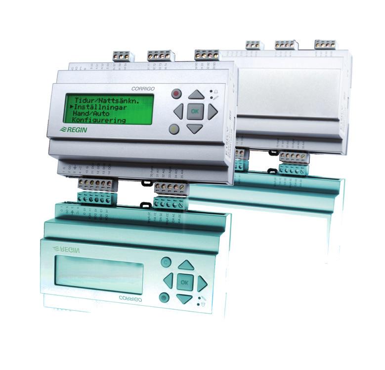
7 Chapter 2 About Corrigo E Corrigo E series comprises three model sizes: 8, 15 or 28 in-/outputs. In each model of Corrigo E generation 2, all applications are loaded in a separate memory area. The models have article number E...-S (where S stands for Second generation). From version 3.0, there are models with two communication ports. By connecting one/two expansion controllers to port two on these units, it is possible to increase the number of inputs and outputs. The 2-port Corrigo models have article number E...2-S (where the number two stands for 2 ports). For more detailed information, see chapter 17. The controllers are available with or without front panel display and buttons. For units without front panel display and buttons a separate, cable-connected terminal E-DSP with display and buttons is available. All configuration and normal handling can be done using the display and buttons or using the configuration tool E tool, installed on a PC and connected via the communication cable E-cable. News in version 3.1 Models with two ports that can control two VACON/Lenze/Omron/Emerson frequency converters via Modbus communication. See chapter 17 and section The access level System is now called Admin to comply better with other Regin systems. New start-up function which makes it possible to block automatic restart at power-up. See section New function for preheating or precooling of the intake air via an underground intake channel. See section New temperature sensor and flow control inputs for supervision. See section New function for setpoint compensation at pressure/flow control. Read more under Extra compensation curve in section New function for free heating which works as reverse cooling recovery. Read more under "Free heating below. It is now possible to combine communication with a frequency converter via Modbus and with an expansion unit. See section Application choice On delivery, the main memory in the Corrigo is empty. All the application programs that can be run in the Corrigo are located in a separate memory area. On the first start-up, the controller will start a special program for downloading a suitable application and suitable languages to the main memory. For certain customised models, an application has already been selected when the product is delivered. If so, the selected application will be started immediately. Corrigo E Controller 08:01:01 00:00 Select application with down arrow First press OK to set the date and time. Use the up and down arrows to change values and the right and left arrows to move between fields. When the date has been set, press OK and the cursor will move to the scheduler. Set the time in the same way as the date and press OK to confirm. Manual Corrigo E Ventilation, revision N Chapter 2 About Corrigo E 7
8 Press down arrow to go to Application choices. ->Ventilation Heating Boiler Expansion Unit 1 Expansion Unit 2 Use the up and down arrows to move the cursor in the left edge of the display to the application you wish to load. Press right arrow to choose the selected application and go to Language choice. Ventilation Choose language English Accept changes:no Press OK to choose language. Use the up and down arrows to move between languages and press OK to confirm your choice. When another language than English is chosen, both English and the selected language will be loaded. To make the final confirmation of the created programs and language choices, change No to Yes and confirm by pressing OK. After a few seconds, the display will show a start display in English for the chosen application. After another few seconds, the display text will change to the selected language, if another language than English has been selected. Regulator vent. sys 08:06:03 09:32 System:Stopped Sp: 19.5 Act: 20.1 C Ventilation application The temperature controller is based on a supply air PI-controller for heating control with a preprogrammed set of control modes. A number of different control functions as well as analogue and digital in- and output functions can be bound to this controller. The choice of which functions are to be used is free, the only restriction is the physical number of inputs and outputs of the different models. The maximum number of I/Os is 3*28 (a 2-port Corrigo with two expansion controllers). The Corrigo is designed for DIN-rail mounting. The program for an air handling unit contains, apart from other things, the following functions: Different temperature control modes Supply air temperature control, with or without outdoor temperature compensation Room temperature control (cascade controller). Extract air temperature control (cascade controller). Seasonal switching between supply air temperature control and room/extract air temperature control. Extra, separate temperature control circuit for after-heaters etc. With control of: Heat exchanger (Liquid connected-, plate- or rotating) or mixing dampers. Heating coil; Water with frost protection or electric. Chiller: Water-heated or DX in up to three steps. Circulation pumps heating, cooling, exchanger. Manual Corrigo E Ventilation, revision N Chapter 2 About Corrigo E 8
9 Fan control 1- or 2-speed supply air fans and extract air fans. Frequency controlled supply and extract air fans with pressure or flow control, manual control or external control from a VAV system. Pressure controlled supply air fan with slave connected extract air fan (output dependent or flow dependent). Humidity control Either humidification or dehumidification, or both humidification and dehumidification. Timer control For starting and stopping the unit. Up to five timer outputs for control of external functions such as lighting, doorlocks etc. Demand control In buildings with strongly varying occupancy the fan speeds or mixing dampers can be controlled by the air quality measured by a CO 2 /VOC sensor. Support control When using the control function room control or extract air temperature control, it is possible to utilise support-heating and/or support-cooling. Minimum running time is settable minutes. (factory setting 20 minutes). Free cooling The function is used during the summer to cool the building during the night using cool outdoor air thereby reducing the need to run chillers during the day. The function can also be activated during daytime if the temperature so allows. Enthalpy control for free cooling/heating This function is used to override the mixing damper to increasing recirculation depending on the result of the enthalpy calculation. Cooling recovery If the extract air is colder than the outdoor air and cooling is required, the heat exchanger control is reversed in order to return the cool extract air. This function can also be used for heating, see Free heating below. Free heating If the extract air is cooler than the outdoor air and heating is required, outdoor air will primarily be used. Recirculation control Recirculation of air using a supply air fan and recirculation damper, with or without temperature control. Pretreatment Preheating or precooling of the intake air via an underground intake channel. Manual Corrigo E Ventilation, revision N Chapter 2 About Corrigo E 9
10 Step controllers Heating/Cooling As an alternative to the analogue control of Actuator heating Y1 or Actuator cooling Y3, step controllers can be used to control heating or cooling in steps using digital control. Corrigo E hardware overview Model 8 8D 15 15D 28 28D Analogue Inputs Digital Inputs Universal Inputs Analogue Outputs Digital Outputs RS485* Yes Yes Yes Yes Yes Yes LON Option Option Option Option Option Option WEB (TCP/IP) Option Option Option Option Option Option 2-port No No Option Option Option Option Display No Yes No Yes No Yes Ext. display Option No Option No Option No *Communication port RS485 is not available for option WEB (TCP/IP). However, a 2-port Corrigo with TCP/IP and RS485 can be selected, where RS485 is used for expansion controllers etc. Corrigo E model overview Model with display Model without display Description E8D-S, E15D-S, E28D-S E8-S, E15-S, E28-S Standard controller with RS485 port E8D-S-LON, E15D-S-LON, E28D-S-LON E8D-S-WEB, E15D-S-WEB, E28D-S-WEB E8-S-LON, E15-S-LON, E28-S-LON E8-S-WEB, E15-S-WEB. E28-S-WEB Controller with both LON and RS485 ports Controller with TCP/IP port and built-in webserver E152D-S, E282D-S E152-S. E282-S Controller with two RS485 ports for connection of expansion units E152D-S-WEB, E282D-S- WEB E152-S-WEB, E282-S-WEB Controller with RS485 port and built-in webserver. For connection of expansion units. Technical data Protection class... IP20 Display... 4 rows of 20 characters. Background illumination. LEDs Yellow... Settable parameter Red... Alarm indication Clock... Year base 24 hour clock with battery backup. Automatic summer-/winter-time changeover. Operating system... EXOreal Supply voltage V AC ±15%, Hz or V DC Power consumption... 5 VA, 3 W (DC), model WEB: 9 VA, 5 W (DC) Dimensions x123x60 (WxHxD incl. terminals) Casing... Standard Euronorm (8.5 modules wide) Mounting... On DIN-rail Operation Climatic conditions according to IEC Class 3k5 Ambient temperature C Manual Corrigo E Ventilation, revision N Chapter 2 About Corrigo E 10
11 Ambient humidity... Max 95% RH Mechanical requirements according to IEC Class 3M3 Vibration... IEC , Test FC, vibration Sinusoidal Shock... IEC , Test Ea Transport Climatic conditions according to IEC Class 2k3 Ambient temperature C Ambient humidity... Max 95% RH Mechanical requirements according to IEC Class 2M2 Vibration... IEC , Test FC, vibration Sinusoidal Shock... IEC , Test Ea Free fall...iec , Test Ed Storage Climatic conditions according to IEC Class 1k3 Ambient temperature C Ambient humidity... Max 95% RH Battery Type...Replaceable Lithium cell, CR2032 Battery life... Better than 5 years Warning... Low battery warning Battery backup... Memory and real time clock Communication EXOline Port 1, insulated via a built-in RS485 contact. EXOline Port 2, insulated via a built-in RS485 contact (only 2-port Corrigo models). The basic version of Corrigo E can communicate with Modbus. You do not need an activation code. Corrigo E can be ordered with a communication port for TCP/IP or LON. CE-marking Conforms with the EMC standards: CENELEC EN :2001, CENELEC EN :2001. Inputs Analogue inputs AI... Settable 0 10 V DC or PT1000, 12 bit A/D Digital inputs DI... Potential-free closure Universal inputs UI... Can be set to act as either an analogue input or... a digital input with specifications as above Outputs Analogue outputs AO... Configurable 0 10 V DC; 2 10 V DC; V DC or 10 2 V DC 8 bit D/A short-circuit protected Digital outputs DO... Mosfet outputs, 24 V AC/DC, 2 A continuous. Totally max 8 A. Options LON... FT3150, gives a second communication route WEB (TCP/IP-port)... Replaces RS485 for EXOline (Port 1) communication 2-port Corrigo models... Two serial ports or one serial port and one TCP/IP port External hand terminal, E-DSP... For use with Corrigo E units without display Manual Corrigo E Ventilation, revision N Chapter 2 About Corrigo E 11
12 Position of the terminals on Corrigo E Manual Corrigo E Ventilation, revision N Chapter 2 About Corrigo E 12
13 Chapter 3 Installation and wiring 3.1 Installation Corrigo E can be mounted in a DIN-standard casing (minimum 9 modules), on a DIN-rail in a cabinet or, using a suitable front-mounting kit, in a cabinet door or other control panel. Ambient temperature: 0 50 C. Humidity: Max. 90 % RH, non-condensing. The picture below shows a wiring example for Corrigo E28. G G C Terminal4 Contact G0 G Actuator Y V DC Corrigo E28 G + G0 - C B + A N E Exoline/ Modbus Net+ Net- Egnd LON DO1-8 RJ45 TCP/IP GDO DO1 DO2 DO3 DO4 DO5 DO6 DO7 DI1 DI2 DI3 DI4 DI5 DI6 DI7 DI8 Agnd AO1 AO2 AO3 AO4 AO5 Ext. disp. RJ12 DI1-8 AI1-4 Agnd AI1 AI2 Agnd AI3 AI4 AO1-5 UI Agnd UI1 UI2 Agnd UI3 UI VAC L N DI-contacts 3-point actuator 24VAC Lamp 24VAC Relay 24VAC - + Transmitter 0-10V DC Temp. sensors Pt1000 +C Term. 4 Contact 3.2 Wiring At the end of this chapter there are wiring diagrams showing the factory set configuration. There are also empty wiring diagrams. Since the function of most of the inputs and outputs depends on the programming of the unit the final wiring diagram cannot be filled in until the installer has decided how to use the inputs/outputs. It is important to make sure that the wiring is correctly done and in accordance with the instructions given in this manual Supply voltage 24 V AC ±15%, Hz or V DC If the Corrigo E and the actuators connected to it share the same transformer it is essential that the same transformer-pole is used as reference for all the equipment. Failure to do so will prevent the equipment from functioning as intended and may also lead to damages. Manual Corrigo E Ventilation, revision N Chapter 3 Installation and wiring 13
14 3.2.2 Inputs and outputs The list of input and output functions in section is a handy instrument to help you keep track of which inputs and outputs you will need to configure. Analogue inputs Analogue inputs must refer to an Agnd terminal placed in the same terminal block as the input being wired. Analogue inputs can, depending on the configuration, be used for either PT1000 temperature sensors or for 0 10 V DC analogue input signals, for example from a pressure transmitter. Digital inputs Digital inputs must refer to +C on terminal 4. Digital inputs may only be wired to voltage-free contacts. Any external voltage applied to a digital input may harm the unit. The input signal can be set to either NO or NC. Universal inputs A universal input can be configured to act as either an analogue input or as a digital input. A universal input configured as an analogue input can, depending on the configuration, be used for either PT1000 temperature sensors or for 0 10 V DC analogue input signals, for example from a pressure transmitter. Universal inputs configured as an analogue input must refer to an Agnd terminal placed in the same terminal block as the input being wired. A universal input configured as a digital input must, just like other digital inputs refer to C+ on terminal 4. It may only be wired to voltage-free contacts. Analogue outputs Analogue outputs must refer to the Agnd terminal placed in the AO terminal block. All analogue outputs can be individually set to any one of the following signals: 0 10 V DC 2 10 V DC 10 0 V DC 10 2 V DC If the Corrigo E and the actuators connected to it share the same transformer it is essential that the same transformer-pole is used as reference for all the equipment. Failure to do so will prevent the equipment from functioning as intended and may also lead to damages. Digital outputs Digital outputs should normally refer to G DO on terminal 10. G DO is internally connected to G on terminal 1 and supplies 24 V AC or DC depending on the choice of supply voltage. All the digital outputs are controlled by MOSFET transistors. The outputs are internally connected with G 0 and can deliver max 2 A per output. However, the total power for all the DOs must not be over 8 A. A number of different wiring alternatives are possible depending on the type of supply voltage to the Corrigo and the relay type. Manual Corrigo E Ventilation, revision N Chapter 3 Installation and wiring 14
15 24 V AC supply and 24 V AC relays 24 VAC L N G G V DC supply and 24 V DC relays + 24 V DC - G G V AC supply and 24 V DC relays 24 V DC VAC L N G G Manual Corrigo E Ventilation, revision N Chapter 3 Installation and wiring 15
16 24 V DC supply and 24 V AC relays 24 VAC L N + 24 V DC - G G Input and outputlists The lists below are intended to be used during commissioning to help you keep track of the desired input and output functions. The left column contains a description of the in-/output signal, the middle column displays the name of the corresponding signal in E tool and the right column shows the text displayed in the Corrigo E controller. Analogue input signal Description E tool Display Outdoor temperature sensor Outdoor Temp Outdoortemp Supply air temperature sensor Supply Air Temp Supplytemp Extract air temperature sensor Extract Air Temp Extracttemp Exhaust air temperature sensor Exhaust Air Temp Exhausttemp Room temperature sensor 1 Room Temp 1 Roomtemp1 Room temperature sensor 2 Room Temp 2 Roomtemp2 CO 2 sensor, 0 10 V DC CO2 Sensor CO2 Pressure transmitter supply air, 0 10 V DC Pressure transmitter extract air, 0 10 V DC SAF Pressure EAF Pressure SAF pressure EAF pressure De-icing sensor, heat exchanger Deicing Temp Deicingtemp Frost protection sensor Frost Protection Temp Frost prot. temp Room humidity sensor Humidity Room Humidity room Duct humidity sensor Humidity Duct Humidity duct Outdoor humidity sensor Humidity Outdoor Humidity out Temperature sensor, Extra controller Extra unit temp Extra unit temp External control supply air fan External control SAF SAF ext. Ctrl External control extract air fan External control EAF EAF ext. Ctrl Pressure transmitter supply air 2 SAF Pressure 2 SAF pressure 2 Intake temperature Intake Temp Intaketemp Extra temperature sensor 1 Extra Sensor Temp 1 Extrasensor Manual Corrigo E Ventilation, revision N Chapter 3 Installation and wiring 16
17 Description E tool Display Extra temperature sensor 2 Extra Sensor Temp 2 Extrasensor 2 Extra temperature sensor 3 Extra Sensor Temp 3 Extrasensor 3 Extra temperature sensor 4 Extra Sensor Temp 4 Extrasensor 4 Extra temperature sensor 5 Extra Sensor Temp 5 Extrasensor 5 Extra pressure transmitter supply air Extra SAF Pressure SAF pressure 2 Extra pressure transmitter extract air Extra EAF Pressure EAF pressure 2 Digital input signal Description E tool Display Filter guard, supply air Filter Guard 1 Filter alarm 1 Filter guard, extract air Filter Guard 2 Filter alarm 2 Run-indication/alarm circulation pump, Heating Heat Pump Indication P1-Heating Run-indication/alarm circulation pump, exchanger Run-indication/alarm circulation pump, Cooling Exchange Pump Indication Cooling Pump Indication P1-Exchanger P1-Cooling Fire alarm Fire Alarm Fire alarm Fire damper end-switch monitoring Fire Damper Indication Fire damper-ind Extended operation, Normal Extended Operation, Normal Ext run 1/1 Extended operation, Reduced Extended Operation, Reduced Ext run 1/2 External switch External Switch External switch External alarm External Alarm External alarm Flow switch Flow Switch Flow guard Rotation guard exchanger Exchange Rotation Rot.sent.exch Run-indication/alarm supply air fan SAF Indication SAF-Ind Run-indication/alarm extract air fan EAF Indication EAF-Ind Deicing thermostat exchanger Deicing De-icing Frost protection thermostat water heater Frost Protection Frostprotection High temperature limit switch Overheated Electric heater Overheatprotection Recirculation start Recirculation Recirculation Change over Change over Change over The universal inputs on Corrigo E28 can, individually, be configured as either analogue inputs using any of the analogue input signals above or as digital inputs using any of the digital inputs above. Manual Corrigo E Ventilation, revision N Chapter 3 Installation and wiring 17
18 Analogue output signal Description E tool Display Y1 Actuator Heating Heating Y1 Y1-Heating Y2 Actuator Exchanger Exchanger Y2 Y2-Exchanger Y3 Actuator Cooling Cooling Y3 Y3-Cooling Frequency converter, supply air fan SAF SAF Frequency converter, extract air fan EAF EAF Actuator Humidity control Humidity Y6-Humidity Split of any one of temp outputs Y1, Y2 Split Sequence or Y3 Extra controller Extra unit control ExtraUnitCtrlVa Y1 Heating / Y3 Cooling, Change-over output Y1 Heating/Y3 Cooling Y1-Heat/Y3-Cool Y4 Extra Sequence Extra Sequence Y4 Y4-Extra Sequen Digital output signal Description E tool Display Start/stop Supply air fan Normal SAF Start 1/1 Normal Speed SAF 1/1-speed Start/stop Extract air fan Normal EAF Start 1/1 Normal Speed EAF 1/1-speed Start/stop Supply air fan Reduced Start/stop Extract air fan Reduced SAF Start 1/2 Reduced Speed SAF 1/2-speed EAF Start 1/2 Reduced Speed EAF 1/2-speed Start/stop circulation pump, heating Heating Pump Start P1-Heating Fire damper Fire Damper Fire damper Sum alarm A- and B-alarm Sum Alarm Sum alarm Sum alarm A-alarm Sum Alarm A A-sum alarm Sum alarm B-alarm Sum Alarm B B-sum alarm Start/stop circulation pump, cooling Cooling Pump Start P1-Cooling Start/stop circulation pump, liquid exchanger Activation-signal SAF frequency converter Activation-signal EAF frequency converter Exchanger Start SAF Freq Start EAF Freq Start P1-Exchanger SAF-frequence EAF-frequence Activate heating Heating Activate Heat start Activate cooling Cooling Activate Cool start Activate exchanger Exchanger Activate Exch start Exhaust air close-off damper Exhaust Air Damper Exhaust air d Fresh air close-off damper Outdoor Air Damper Fresh air dam Recirculation damper Recirculation Air Damper Recirc. dampe Heating 3-position actuator, increase Heating Increase Heat-inc Heating 3-position actuator, decrease Heating Decrease Heat-dec Exchanger 3-position actuator, increase Exchanger Increase Exchanger 3-position actuator, decrease Exchanger Decrease Exch-inc Exch-dec Manual Corrigo E Ventilation, revision N Chapter 3 Installation and wiring 18
19 Description E tool Display Cooling 3-position actuator, increase Cooling Increase Cool-inc Cooling 3-position actuator, decrease Cooling Decrease Cool-dec Step controller heating, step 1 Heat Step 1 Heat step1 Step controller heating, step 2 Heat Step 2 Heat step2 Step controller heating, step 3 Heat Step 3 Heat step3 Step controller heating, step 4 Heat Step 4 Heat step4 Step controller cooling, step 1 Cool Step 1 Cool step1 Step controller cooling, step 2 Cool Step 2 Cool step2 Step controller cooling, step 3 Cool Step 3 Cool step3 Extra time channel 1 Time Channel 1 Timer 1 Extra time channel 2 Time Channel 2 Timer 2 Extra time channel 3 Time Channel 3 Timer 3 Extra time channel 4 Time Channel 4 Timer 4 Extra time channel 5 Time Channel 5 Timer 5 Humidity Humidity/DeHumidity Humidity External controller active Extra unit active ExtraUnitActi Heating/cooling step 1 Heat/cool step 1 HeatCoolStep1 Heating/cooling step 2 Heat/cool step 2 HeatCoolStep2 Heating/cooling step 3 Heat/cool step 3 HeatCoolStep3 Free cooling operation Free cool run Free cool run Manual Corrigo E Ventilation, revision N Chapter 3 Installation and wiring 19
20 Wiring diagram Corrigo E28-S (default in- and output configuration) (See also picture of the position of the terminals on page 7) 8) 1 2 G G0 Supply voltage 24 V AC or 24 V DC, ±15%. 50/60 Hz B A 3 Protective earth 52 N 4 +C +24 V DC. Reference for digital inputs DI. 53 E RS485 EXOline / Modbus (not in WEB (TCP/IP) models) 10 G DO Reference for digital outputs DO. 57 Net+ 11 DO1 Start/stop supply air fan (SAF) 1/1-speed 58 Net- LON-connection (LON-versions only) 12 DO2 Start/stop extract air fan (EAF) 1/1-speed 59 Egnd 13 DO3 Start/stop supply air fan (SAF) 1/2-speed 14 DO4 Start/stop extract air fan (EAF) 1/2-speed 71 DI1 Filter guard, supply air and extract air 15 DO5 Start/stop Circulation pump, Heating 72 DI2 Run indication /alarm, Circ. pump Heating 16 DO6 Fire damper 73 DI3 Run indication /alarm, Circ. pump Cooling 17 DO7 Sum alarm A + B 74 DI4 Fire alarm 75 DI5 Fire damper end-switch monitoring 30 Agnd Reference pole for analogue inputs AI 76 DI6 Extended running 1/1-speed 31 AI1 Outdoor temperature sensor 77 DI7 External alarm 32 AI2 Supply air temperature sensor 78 DI8 External switch 33 Agnd Reference pole for analogue inputs AI 34 AI3 Extract air temperature sensor 90 Agnd Reference pole for analogue outputs AO 35 AI4 Room temperature sensor 1 91 AO1 Y1 Actuator Heating 92 AO2 Y2 Actuator Exchanger 40 Agnd Reference pole for universal inputs UI 93 AO3 Y3 Actuator Cooling 41 UI1 DI Run indication / Motor protection SAF 94 AO4 Not used 42 UI2 DI Run indication / Motor protection EAF 95 AO5 Not used 43 Agnd Reference pole for universal inputs UI 44 UI3 De-icing sensor, heat exchanger 45 UI4 Frost protection sensor Manual Corrigo E Ventilation, revision N Chapter 3 Installation and wiring 20
21 Wiring diagram Corrigo E15-S (default in- and output configuration) 1 2 G G0 Supply voltage 24 V AC or 24 V DC, ±15%. 50/60 Hz B A 3 Protective earth 52 N 4 +C +24 V DC. Reference for digital inputs DI. 53 E RS485 EXOline / Modbus (not in WEB (TCP/IP) models) 10 G DO Reference for digital outputs DO. 57 Net+ 11 DO1 Start/stop supply air fan (SAF) 1/1-speed 58 Net- LON-connection (LON-versions only) 12 DO2 Start/stop extract air fan (EAF) 1/1-speed 59 Egnd 13 DO3 Start/stop Circulation pump, Heating 14 DO4 Sum alarm A + B 71 DI1 Run indication / Motor protection SAF 72 DI2 Run indication / Motor protection EAF 30 Agnd Reference pole for analogue inputs AI 73 DI3 Run indication /alarm, Circ. pump Heating 31 AI1 Outdoor temperature sensor 74 DI4 Extended running 32 AI2 Supply air temperature sensor 33 Agnd Reference pole for analogue inputs AI 90 Agnd Reference pole for analogue outputs AO 34 AI3 Frost protection sensor 91 AO1 Y1 Actuator Heating 35 AI4 Room temperature sensor 1 92 AO2 Y2 Actuator Exchanger 93 AO3 Y3 Actuator Cooling Wiring diagram Corrigo E8-S (default in- and output configuration) 1 2 G G0 Supply voltage 24 V AC or 24 V DC, ±15%. 50/60 Hz B A 3 Protective earth 52 N 4 +C +24 V DC. Reference for digital inputs DI. 53 E RS485 EXOline / Modbus (not in WEB (TCP/IP) models) 10 G DO Reference for digital outputs DO. 57 Net+ 11 DO1 Start/stop supply air fan (SAF) 1/1-speed 58 Net- 12 DO2 Start/stop Circulation pump, Heating 59 Egnd LON-connection (LON-versions only) 30 Agnd Reference pole for analogue inputs AI 71 DI1 Run indication / Motor protection SAF 31 AI1 Outdoor temperature sensor 72 DI2 Run indication /alarm, Circ. pump Heating 32 AI2 Supply air temperature sensor 73 DI3 High temp. limit switch / Frost prot. thermostat 90 Agnd Reference pole for analogue outputs AO 91 AO1 Y1 Actuator Heating Manual Corrigo E Ventilation, revision N Chapter 3 Installation and wiring 21
22 Empty wiring diagram Corrigo E28-S 1 2 G G0 Supply voltage 24 V AC or 24 V DC, ±15%. 50/60 Hz B A 3 Protective earth 52 N 4 +C +24 V DC. Reference for digital inputs DI. 53 E RS485 EXOline / Modbus (not in WEB (TCP/IP) models) 10 G DO Reference for digital outputs DO. 57 Net+ 11 DO1 58 Net- LON-connection (LON-versions only) 12 DO2 59 Egnd 13 DO3 14 DO4 71 DI1 15 DO5 72 DI2 16 DO6 73 DI3 17 DO7 74 DI4 75 DI5 30 Agnd Reference pole for analogue inputs AI 76 DI6 31 AI1 77 DI7 32 AI2 78 DI8 33 Agnd Reference pole for analogue inputs AI 34 AI3 90 Agnd Reference pole for analogue outputs AO 35 AI4 91 AO1 92 AO2 40 Agnd Reference pole for universal inputs UI 93 AO3 41 UI1 94 AO4 42 UI2 95 AO5 43 Agnd Reference pole for universal inputs UI 44 UI3 45 UI4 Empty wiring diagram Corrigo E15-S 1 2 G G0 Supply voltage 24 V AC or 24 V DC, ±15%. 50/60 Hz B A 3 Protective earth 52 N 4 +C +24 V DC. Reference for digital inputs DI. 53 E RS485 EXOline / Modbus (not in WEB (TCP/IP) models) 10 G DO Reference for digital outputs DO. 57 Net+ 11 DO1 58 Net- LON-connection (LON-versions only) 12 DO2 59 Egnd 13 DO3 14 DO4 71 DI1 72 DI2 30 Agnd Reference pole for analogue inputs AI 73 DI3 31 AI1 74 DI4 32 AI2 33 Agnd Reference pole for analogue inputs AI 90 Agnd Reference pole for analogue outputs AO 34 AI3 91 AO1 35 AI4 92 AO2 93 AO3 Manual Corrigo E Ventilation, revision N Chapter 3 Installation and wiring 22
23 Empty wiring diagram Corrigo E28-S 1 2 G G0 Supply voltage 24 V AC or 24 V DC, ±15%. 50/60 Hz B A 3 Protective earth 52 N 4 +C +24 V DC. Reference for digital inputs DI. 53 E RS485 EXOline / Modbus (not in WEB (TCP/IP) models) 10 G DO Reference for digital outputs DO. 57 Net+ 11 DO1 58 Net- 12 DO2 59 Egnd LON-connection (LON-versions only) 30 Agnd Reference pole for analogue inputs AI 71 DI1 31 AI1 72 DI2 32 AI2 73 DI3 90 Agnd Reference pole for analogue outputs AO 91 AO1 Empty wiring diagram Corrigo E282-S 1 G Supply voltage 24 V AC or 24 V DC, 50 B 2 G0 ±15%. 50/60 Hz 51 A 3 Protective earth 52 N RS485 EXOline / Modbus (Port 1) 4 +C +24 V DC. Reference for digital inputs DI. 53 E 54 B 10 G DO Reference for digital outputs DO. 55 A 11 DO1 56 N RS485 EXOline / Modbus (Port 2) 12 DO2 57 E 13 DO3 14 DO4 71 DI1 15 DO5 72 DI2 16 DO6 73 DI3 17 DO7 74 DI4 75 DI5 30 Agnd Reference pole for analogue inputs AI 76 DI6 31 AI1 77 DI7 32 AI2 78 DI8 33 Agnd Reference pole for analogue inputs AI 34 AI3 90 Agnd Reference pole for analogue outputs AO 35 AI4 91 AO1 92 AO2 40 Agnd Reference pole for universal inputs UI 93 AO3 41 UI1 94 AO4 42 UI2 95 AO5 43 Agnd Reference pole for universal inputs UI 44 UI3 45 UI4 Manual Corrigo E Ventilation, revision N Chapter 3 Installation and wiring 23
24 Empty wiring diagram Corrigo E152-S 1 G Supply voltage 24 V AC or 24 V DC, 50 B 2 G0 ±15%. 50/60 Hz 51 A 3 Protective earth 52 N RS485 EXOline / Modbus (Port 1) 4 +C +24 V DC. Reference for digital inputs DI. 53 E 54 B 10 G DO Reference for digital outputs DO. 55 A 11 DO1 56 N RS485 EXOline / Modbus (Port 2) 12 DO2 57 E 13 DO3 14 DO4 71 DI1 72 DI2 30 Agnd Reference pole for analogue inputs AI 73 DI3 31 AI1 74 DI4 32 AI2 33 Agnd Reference pole for analogue inputs AI 90 Agnd Reference pole for analogue outputs AO 34 AI3 91 AO1 35 AI4 92 AO2 93 AO3 Manual Corrigo E Ventilation, revision N Chapter 3 Installation and wiring 24
25 Chapter 4 Commissioning General Before the Corrigo can be used it must be configured, inputs and outputs must be assigned and all relevant parameters must be set. All commissioning can be done using the Corrigo front panel display and buttons or using the display unit E-DSP. Corrigo E tool The best way however, is to configure the Corrigo E by using Corrigo E tool. Corrigo E tool is a PC-based configuration program specially developed to simplify the commissioning of the Corrigo E series. When using E tool the whole configuration and all settings can be done on the computer and then be downloaded to the Corrigo. An infinite number of different configurations can be saved in computer memory for later use. 4.1 How to do it For configuration using E tool, see the E tool manual. For configuration using the front panel there are two ways to go depending on how much help you need. Option 1: Jump straight to chapter 7 and 8, Display, LEDs and buttons and Access rights. After learning how to use the buttons and menu system, connect power to your Corrigo, log on as Admin and go to the menu "Configuration". For the time being, skip the configuration menu In-/Outputs and start by configuring control functions. Run through the configuration menus in order and set whatever functions and parameters you wish to include. Use chapter 6 of this manual for reference. Keep track of which inputs and outputs you will need. To help you, there is a list of input and output functions provided in chapter 3, (3.2.3 Input / Output list.) Finally, configure In-/Outputs. Exit the "Configuration" menu and go to "Settings". Set the control values in "Settings". Set the clock and scheduler functions in "Time Settings". Set the control setpoints in temperature and air control as well as in humidity control if humidity control has been configured Your Corrigo should now be ready to run. Manual Corrigo E Ventilation, revision N Chapter 4 Commissioning 25
26 Option 2: Read this manual in the order given below: The manual has been designed to act as a guide through the commissioning. The last chapters of the manual, not listed below, cover menus and functions that are not used during commissioning. Functional description Start by reading chapter 5. Functional description below. Some functions are essential to the working of the unit and must be included. Others are more of the nature of optional extras which can be excluded. At the end of each function description there is a table of the necessary inputs and outputs to implement the function. At the end of the manual there is a list of all the analogue and digital inputs and outputs. As you read, mark in the list the inputs and outputs you will be using for the application you are building. Note that the universal inputs in Corrigo E28 can, individually, be configured as either analogue or digital inputs. Display, buttons and LEDs Read chapter 7 on how to use the front panel buttons to navigate the Corrigo E menu system. Access rights Chapter 8. Learn how to log on to the Corrigo E. Configuration Chapter 16. Configuration. Connect power to the Corrigo. Using the buttons and menu system, go through the configuration menus covering the functions you wish to use. On delivery the units already have the inputs and outputs assigned to various functions. These can, of course, be changed. In chapter 3 Installation and wiring there are two sets of wiring diagrams, one set showing the pre-configured input / output configuration and one set where you can fill your own configuration choices. Settings Chapter 15 Set the control parameters, P-band, I-time for the temperature control. Set the control parameters for the pressure control if you have pressure- or flow- controlled fans. Set the control parameters for the humidity control if activated. Set the alarm parameters; alarm levels and delay times. Time settings Chapter 13 Set the clock and calendar functions. Setpoints Chapters 10, 11 and 12: Set all the setpoints for all active control loops. Manual/Auto Chapter 14 Learn to use manual control. Very useful for testing out your system. Manual Corrigo E Ventilation, revision N Chapter 4 Commissioning 26
27 Other functions Chapter 18 Alarm handling etc. Manual Corrigo E Ventilation, revision N Chapter 4 Commissioning 27
28 Chapter 5 Functional description 5.1 Temperature control General Corrigo E has a choice of the following control modes: 1. Supply air control 2. Outdoor temperature compensated supply air control 3. Cascaded room temperature control 4. Cascade connected extract air temperature control 5. Outdoor temperature dependent switching between room control and supply air control 6. Outdoor temperature dependent switching between extract air control and supply air control The supply air temperature controller is reverse acting, i. e. the output will increase for decreasing temperature. The controller is a PI-controller with settable P-band and I-time. In the first two modes the supply air temperature will be controlled using the supply air temperature and the user setpoint values as control inputs. In modes three and four the supply air is controlled as part of a cascade controller together with the room/extract temperature controller. The room/extract temperature offset will dictate the supply air temperature setpoint. Mode five and six vary according to the outdoor temperature: Supply air control in winter and cascaded room control or cascaded extract air control in summer. In applications with mixing dampers instead of heat exchanger the signal for the damper control will be reversed compared to the signal for heat exchanger control i. e. decreasing signal on increasing heat demand. This is done automatically on configuring the exchanger output = dampers. The heater can be either a hot water heater battery or an electric heater. Outputs The supply air controller output is split between one or more of the output blocks "Heating Y1", "Exchanger Y2" and "Cooling Y3". Each of these output blocks can be bound to either an analogue 0 10 V DC output or to two digital 3-position increase/decrease outputs. Each output block has two parameters for setting the control range: Heating Controller Output signal (HCOut) at which the output should be 0 % Heating Controller Output signal (HCOut) at which the output should be 100 % These settings are used to establish the output activation order and to split the P-band between the outputs. Example: 0 % Cooling at HCOut = 30 % 100 % Cooling at HCOut = 0 % 0 % heat exch. at HCOut = 32 % 100 % heat exch. at HCOut = 50 % Manual Corrigo E Ventilation, revision N Chapter 5 Functional description 28
29 0 % Heating at HCOut = 54 % 100 % Heating at HCOut = 100 % Output signal 100% 0% Controller signal 100% Cooling Heat exch. Heating 54% 50% 32% 30% 0% Heat demand In addition to these three, it is possible to connect another anologue output signal to control an optional sequence, Y4 Extra sequence. "Y4 Extra sequence" is set in the same way as above. You can also choose if you want the output to be affected by the enthalpy control and/or the cooling recovery. 0 % at HCOut = 0 % 100 % at HCOut = 0 % It is also possible to split one of the three analogue outputs heating, heat exchanger or cooling into two equal parts to give a fourth output sequence for temperature control Control modes 1. Supply air control The supply air temperature is kept at the setpoint value by controlling the output signals for "Heating Y1", "Exchanger Y2", "Cooling Y3" and "Extra sequence Y4". A single PI control loop is used. The setpoint value is set using the front panel or alternatively using an external setpoint device. Alarms which are activated when the supply air temperature is too high or too low are active. Alarm for control offset of the supply air temperature is active. 2. Outdoor temperature compensated supply air control The supply air temperature setpoint is outdoor temperature compensated using a control curve with 6 node points. The supply air temperature is kept at the setpoint value by controlling the output signals for "Y1 Heating", "Y2 Heat exchanger", "Y3 Cooling" and "Y4 Extra sequence". A single PI control loop is used. Alarms which are activated when the supply air temperature is too high or too low are active. Alarm for control offset of the supply air temperature is active. Manual Corrigo E Ventilation, revision N Chapter 5 Functional description 29
30 3. Cascaded room temperature control Cascade control of room temperature and supply air temperature to achieve a constant, settable room temperature. The room controller output signal generates the supply air controller s setpoint value. One or two room sensors can be connected. If two sensors are connected the average of their values will be used. The number of room sensors is detected automatically. The room temperature is kept at the setpoint value by controlling the output signals for "Y1 Heating", "Y2 Heat exchanger", "Y3 Cooling" and "Y4 Extra sequence". Two PI loops are used. The room setpoint value is set using the front panel or alternatively using an external setpoint device. 4. Cascaded extract air temperature control Cascade control of extract air temperature and supply air temperature to achieve a constant, settable room temperature. The extract air controller output signal generates the supply air controller s setpoint value. The extract air temperature is kept at the setpoint value by controlling the output signals for "Y1 Heating", "Y2 Heat exchanger", "Y3 Cooling" and "Y4 Extra sequence". Two PI loops are used. The extract air setpoint value is set using the front panel or alternatively using an external setpoint device. 5. Outdoor temperature dependent switching between supply air temperature control and room temperature control When the outdoor temperature is lower than a settable limit (winter), outdoor compensated supply air temperature control will be active, otherwise (summer) cascaded room temperature control. 6. Outdoor temperature dependent switching between supply air temperature control and extract air temperature control When the outdoor temperature is lower than a settable limit (winter), outdoor compensated supply air temperature control will be active, otherwise (summer) cascaded room temperature control. In- and outputs Control modes AI AI AI AI AI AI Supply air sensor AI AI AI Outdoor temperature sensor AI AI Room sensor AI AI Extract air sensor AO AO AO AO AO AO Y1 Heating 0 10 V DC ** Y2 Exchanger 0 10 V DC AO AO AO AO AO AO ** AO AO AO AO AO AO Y3 Cooling 0 10 V DC ** AO AO AO AO AO AO AO AO AO AO AO AO Y4 Extra sequence V DC Extra split Y1, Y2 or Y V DC (optional) Y1 Heating/Y3 Cooling AO AO AO AO AO AO Change-over (option) DO DO DO DO DO DO Heating 3-pos. increase ** DO DO DO DO DO DO Heating 3-pos. decrease ** DO DO DO DO DO DO Exch. 3-pos. increase ** DO DO DO DO DO DO Exch. 3-pos. decrease ** DO DO DO DO DO DO Cooling 3-pos. increase ** Manual Corrigo E Ventilation, revision N Chapter 5 Functional description 30
31 Control modes DO DO DO DO DO DO Cooling 3-pos. decrease ** ** Choose output type depending on the actuator type: Either AO 0 10 V or DO 3-position increase/decrease Heater types Water heating Control When the unit is in running mode the heating valve is controlled by the analogue output Y1 Heating or by two digital outputs Heating 3-pos. actuator, increase and Heating, 3-pos. actuator, decrease. Frost protection The heater return water temperature is measured using the analogue input Frost protection sensor. Low temperatures will generate an internal, proportional signal that is used to force the heating valve open thereby preventing freeze-up of the heater. The internal signal ( Internal signal ) is 100 % when the signal Frost protection sensor is equal to or lower than Alarm level. When Internal signal reaches 100 % or the digital input Frost protection is activated, the unit is shut down, the heating output is set to completely open mode and an alarm is activated. When Frost protection sensor is higher than Alarm level the signal declines linearly to 0 for Frost protection sensor equal to or higher than Alarm level + Prop. Band. The frost protection alarm level is set in the menu Settings/Alarm settings/alarm limit. 100 % Internal signal Prop.band 0 % Alarm level Frost protection sensor Shutdown mode If frost protection is activated the controller will go into Shutdown mode when the running mode switches to Off. The shutdown controller will control the heating output to maintain a constant settable temperature at the frost protection sensor. Manual Corrigo E Ventilation, revision N Chapter 5 Functional description 31
32 Electric heating Control The heating is controlled using the analogue output Y1 Heating. On activation of the digital input High temp limit/frost protection the unit will be shut down, either according to the stop sequence described in section Start/stop of unit or as an emergency shutdown. The unit will restart after the alarm has been acknowledged and High temp limit/frost protection has reset. Note that activation of the input signal Flow switch will also stop the unit. Control voltage Relay el. heating Contr. voltage High limit thermostat Auxiliary relay Corrigo Wiring suggestion high temp limit when using electric heating. Contactors drawn inactivated. Note: It is important that the high temperature thermostat is hardwired to disconnect the power to the heater to ensure that the heating is shut down when the thermostat is activated even if the Corrigo should be faulty Water heating and electric heating The water heating is controlled by "Y1 Heating", and the electric heating is controlled by the sequence "Split". Split (see the section Split of optional temp sequence) must always be set to "Heating". On increasing heat demand, the water heating is first activated and then, if needed, the electric heating. Frost protection and overheating protection are both active. If "step controller heating" is used, the function is tied to the output signal "Split" Fast stop on overheating If the function "fast stop on overheating" is active, the fans will be immediately stopped when there is an overheating alarm, regardless of the set cool-down time. In- and outputs Water Electric heating heating AI DI** DI DI Frost protection sensor (optional) Frost protection thermostat water heater (optional) High temperature limit switch Flow switch (optional) **Frost protection can also be created using the digital input Frost protection thermostat water heater and an external thermostat. Activation of the input will force the running mode to Off and an alarm will be activated. The heating output is set to completely open, the remaining control outputs are set to zero. Manual Corrigo E Ventilation, revision N Chapter 5 Functional description 32
33 Frost protection thermostat cannot be combined with shutdown mode Heat exchangers The heat exchanger unit can be set to one of the following alternatives: Plate exchanger Rotating exchanger Liquid connected exchanger Mixing dampers Plate exchanger Control The airflow through the exchanger is controlled by a shut-off damper and a by-pass damper. Both dampers are controlled by the same analogue output Y2 Heat exchanger or by two digital outputs Exchanger 3-pos. actuator, increase and Exchanger, 3-pos. actuator, decrease, and are wired so that one opens as the other closes. Defrosting De-icing is activated either when the digital input signal De-icing is activated or when the value of the analogue input De-icing thermostat Exchanger falls below the de-icing limit (-3 C). It is deactivated when the digital input is reset or the analogue input rises above the limit value plus a settable differential. On de-icing: A PI-controller compares the de-icing setpoint with the signal De-icing Exchanger. The lesser of the output signal from this controller and the output from the ordinary controller is used as output to the dampers. Rotating exchanger Control Rotational speed is controlled by the analogue signal Y2 Heat exchanger or by two digital outputs Exchanger 3-pos. actuator, increase and Exchanger, 3-pos. actuator, decrease. A rotation sentinel can be connected to the digital input Rotation sentinel Exchanger. An alarm is generated if this input is activated at the same time as the analogue output signal is higher than 1.0V. Liquid connected exchanger Control A mixing valve in the exchanger circulation system is controlled by the analogue signal Y2 Heat exchanger or by two digital outputs Exchanger 3-pos. actuator, increase and Exchanger, 3-pos. actuator, decrease. The circulation pump (digital output "Start/stop circulation pump, liquid exchanger") is started as soon as the actuator control signal exceeds 0.1 V and is stopped when the valve has been closed for more than 5 minutes. Defrosting De-icing is activated either when the digital input signal De-icing is activated or when the value of the analogue input De-icing thermostat Exchanger falls below the de-icing limit (-3 C). It is deactivated when the digital input is reset or the analogue input rises above the limit value plus a settable differential. Manual Corrigo E Ventilation, revision N Chapter 5 Functional description 33
34 On de-icing: A PI-controller compares the de-icing setpoint with the signal De-icing Exchanger. The lesser of the output signal from this controller and the output from the ordinary controller is used as output to the actuator. Outdoor temp control of exchanger Instead of using Y2 for analogue control of the heat exchanger it can be set to run on-off against outdoor temperature. The function controls a digital output Exch control, which is activated when the outdoor temperature falls below a set value. Mixing dampers Control The analogue output signal Exchanger Y2, or the two digital output signals "Exchanger 3- position, increase" and "Exchanger 3-position, decrease", control two dampers for gradual mixing of outdoor air and recirculated air. In this mode the output signal decreases with increasing heat demand. CO 2 If demand controlled ventilation (see 5.3.2) is activated in combination with mixing dampers, and the CO 2 -value rises above the setpoint value, the dampers will let in more outdoor air. The function is controlled by a PI-controller. Factory settings: P-band 100ppm and I-time 100 seconds. These values can only be changed in E tool. Minimum limit An outdoor air minimum limit for can be set using the front panel. The limit value is settable between 0 and 100 %. In- and outputs Plate Rotating Exch Liquid Dampers AI AI AI AI Outdoor temp. sensor (optional, outd. temp start) DO DO DO DO Activate exchanger (optional, outd. temp start) AI AI De-icing sensor (optional) DI DI De-icing signal (optional) DI Rotation sentinel (optional) If an intake temperature sensor is configured, it must be used instead of the outdoor sensor for the de-icing function TA/Topvex. Start delay exchanger This function delays the exchanger start at start-up of the unit. 100 % exchanger output at start-up After the delay described above, the exchanger output will be 100 % during the set time. Manual Corrigo E Ventilation, revision N Chapter 5 Functional description 34
35 5.1.4 Types of chillers Step controller Heating / DX cooling As alternative or complement to the above mentioned analogue control, heating and cooling can be activated in steps. The internal signal is then used to activate digital outputs for control of the heaters/chillers. Up to four heater outputs and three cooler outputs can be configured. There are two possible modes: Sequential Each output step has individually settable on and off values in percent of the control signal. The number of steps is equal to the number of heater/chiller groups. Minimum on and off times can be set, i.e. the minimum time the step has to be inactive or active for a change to occur. Binary The heater power outputs should be binary weighted (1:2:4:8 for heating, 1:2:4 for cooling). The number of loads to be controlled is set. Thereafter the program will automatically calculate the individual activation levels. Switching differential and minimum on/off times can be set. The number of heating steps will be: 2 no. of groups -1. In binary mode, the analogue output signal may be used to fill out between the steps. The signal will go % between the activation of each step. The load connected to the analogue signal should have the same size as the smallest of the binary groups. In the example below there are 4 heater groups (1:1:2:4) and the total number of heating steps is eight. Y1 = Step controllers and Change-over The digital output signals "Heating/cooling step 1", "Heating/cooling step 2" and "Heating/cooling step 3" are used for step controllers during Change-over control (see section ). They have the same functions as other step controller outputs, but are set to either heating or cooling depending on whether heating or cooling is required. DX cooling with room or extract air control If DX cooling is used in conjunction with room temperature control or extract air temperature control, there are two configuration alternatives, DX cooling or DX cooling with exchanger control. DX cooling without exchanger control When running cascade control, the supply air controller setpoint is normally controlled by the room/extract air controller output signal. When DX cooling is activated, the cooling controller setpoint is lowered to five degrees (adjustable) below the setpoint given by the room/extract air controller. This prevents the DX cooling from being activated/deactivated too often. Manual Corrigo E Ventilation, revision N Chapter 5 Functional description 35
36 DX cooling with exchanger control When running cascade control, the supply air controller setpoint is normally controlled by the room/extract air controller output signal. When DX cooling is activated, the cooling controller setpoint is lowered to five degrees (adjustable) below the setpoint given by the room/extract air controller. This prevents the DX cooling from being activated/deactivated too often. If the supply air temperature falls below the setpoint given by the room/extract air controller, the heat exchanger output will be activated in order to try to maintain the supply air setpoint given by the room/extract air controller. The output uses P-control with a P- band of half the setpoint lowering (adjustable, 2.5 C as default). The setpoint given by the room/extract air controller cannot drop below the set min limit. When there is no longer a cooling demand, the cooling controller setpoint will return to the value given by the room/extract air controller. Note: The function cannot be used if the exchanger signal controls a mixing damper. Example: The room controller gives a supply air setpoint of 16 C. If there is a cooling demand, the cooling controller setpoint is lowered to 11 C (16 5) and DX cooling is activated. Should the supply air temperature fall below 16 C, the exchanger output will be activated and reach 100 % output when the supply air temperature has fallen to 13.5 C (16-2.5). Blocking of DX cooling at low outdoor temperature DX cooling can be blocked when the outdoor temperature is low. It is possible to block the three cooling steps individually or to block all DX cooling. The temperature limits are adjustable (+13 C default) and have a fixed one degree hysteresis. When two DX cooling steps are used with binary function, the cooling effect is divided into three steps. The desired blocking level can be set individually for each of these steps. When three DX cooling steps are used with binary function, the cooling effect is divided into seven steps. However, the controller still only has three blocking level settings. Therefore, Blocking step 1 will apply to binary steps 1 and 2, Blocking step 2 to binary steps 3 and 4, and Blocking step 3 to binary steps 5, 6 and 7. Blocking of DX cooling at low supply air fan speed When DX cooling is used in conjunction with pressure controlled or flow controlled fans it is possible to block DX cooling if the supply air fan control signal falls below a preset values. For sequential control, the blocking level is individually settable for each DX cooling step. When two DX cooling steps are used with binary function, the cooling effect is divided into three steps. The desired blocking level can be set individually for each of these steps. When three DX cooling steps are used with binary function, the cooling effect is divided into seven steps. However, the controller still only has three blocking level settings. Therefore, Blocking step 1 will apply to binary steps 1 and 2, Blocking step 2 to binary steps 3 and 4, and Blocking step 3 to binary steps 5, 6 and 7. Manual Corrigo E Ventilation, revision N Chapter 5 Functional description 36
37 Blocking of DX cooling on cooling pump alarm Corrigo can be configured to block DX cooling on cooling pump alarm. In- and outputs Heating Cooling Heating/Cooling Change-over DO DO DO Step controller, step 1 (optional) DO DO DO Step controller, step 2 (optional) DO DO DO Step controller, step 3 (optional) DO Step controller, step 4 (optional) Override of reduced speed for DX cooling Override to normal quantity of air for DX cooling when the unit runs on reduced quantity of air. The fans can be set to normal operation when cooling is required at high outdoor temperatures (e.g. >14 C, the same temperature limit as for blocking of DX cooling) Support control Support control is normally used when room temperature control or extract air control has been configured. When extract air control is configured a room sensor must be installed. Support control Heating or Support control Cooling will run if Support control is configured, the running mode is in Off-state (timer control OFF and not in extended running) and if conditions call for support control (see below). Minimum run time is settable 0 to 720 minutes (FS= 20 minutes). Support control can also be configured when supply air temperature control is used, if a room sensor is installed. The controller uses the configured min. (FS=15 C) and max. (FS=30 C) limitation values as support control setpoints. However, in this case the min. and max. limitation values cannot be changed. To change the values, temporarily configure room control, change the min. and max. values and then change back to supply air control. Support control can also be configured to start only with the supply air fan. In this mode, the extract air fan is not active. This requires a digital output to be configured, which controls the recirculation damper to open completely so the supply air fan can circulate the air to and from the room. The digital output is called recirculation damper. Support control heating Demand for support control heating is when the room temperature is lower than the start value which is settable 0 to 30 C. The fans will run at the preset speed, the heater and the heat exchanger are controlled by the supply air temperature controller with the configured max limitation for the supply air (FS=30 C) as setpoint and the cooling is shut off (0%). Support control heating stops when the room temperature rises to the stop value and the minimum run time has been exceeded or the running mode changes to On. Support control cooling Demand for support control cooling is when the room temperature is higher than the start value which is settable 20 to 50 C. The fans will run at the preset speed, the heater and the heat exchanger are shut down (0 %) and the cooling is controlled by the supply air temperature controller with the configured minimum limitation (FS=15 C) as setpoint. Support control cooling stops when the temperature falls below the stop value and the minimum run time has been exceeded or the running mode changes to On. Manual Corrigo E Ventilation, revision N Chapter 5 Functional description 37
38 5.1.6 Free cooling This function is used during the summer to cool the building night-time using cool outdoor air, thereby reducing the need for cooling during the day and saving energy. Free cooling requires an outdoor sensor (or an inlet temperature sensor) and either a room sensor or an extract air sensor. The outdoor sensor can be placed in the fresh air inlet duct. Free cooling is only activated when all the start conditions are fulfilled. Start conditions: Less than four days have passed since the unit was last in running mode. The outdoor temperature during the previous running period exceeded a set limit (22 C). It is between 00:00 and 07:00:00 in the day (settable). The timer outputs for "normal speed", "Extended running, Normal" and "External switch" are Off. A timer channel will be On sometime during the recently started 24 hours. If the outdoor sensor is located in the fresh air inlet duct and/or an extract air sensor is selected and ALL the start conditions are fulfilled, free cooling is activated and will run for 3 minutes to ensure that the temperature measurement when using an extract air sensor reflects the corresponding room temperature and that the outdoor temperature sensor senses the outdoor temperature even if it is placed in the fresh air inlet duct. If the outdoor sensor is not located in the fresh air inlet duct and a room sensor is selected, the unit will not start free cooling as long as all the temperatures are not within the start and stop temperature intervals. After three minutes, the stop conditions will be controlled. Stop conditions: Outdoor temp above the set max. value (18 C) or below the set min. value (condensation risk, 10 C). The room temp/extract air temp. is below the set stop value (18 C). The timer outputs for "normal speed", "Extended running, Normal" or "External switch" are On. It is past 07:00:00 in the day. If any stop condition is fulfilled after three minutes, the unit will stop again. Otherwise, operation will continue until a stop condition is fulfilled. When free cooling is active, the fans run at normal speed or the set value for pressure/flow control and the digital output "Free cooling operation" is active. The outputs "Y1-Heating", "Y2-Heat exchanger" and "Y3-Cooling" are shut down. After free cooling has been active, the heating output is blocked for 60 minutes (configurable time). In- and outputs AI AI DO Outdoor temperature sensor or Intake temperature Room sensor or Extract air sensor Free cooling operation Manual Corrigo E Ventilation, revision N Chapter 5 Functional description 38
39 5.1.7 Cooling recovery If the extract air temperature is a settable amount lower than the outdoor temperature, cooling recovery can be activated. When cooling recovery is activated the heat exchanger signal will be reversed to give increasing recovery on increasing cooling demand. The function can also be used for heating: if heating is required and the outdoor temperature is higher than the extract air temperature, outdoor air will primarily be used. 100% Output signals 0% Controller signal Cooling Exchanger In- and outputs AI Outdoor temperature sensor AI Extract air sensor Enthalpy control Calculating the enthalpy means to calculate the energy content of the air, taking into consideration both the temperature and the air humidity. The value is given in energy per kilogram air (kj/kg). If enthalpy control is configured, the enthalpy is calculated both indoors and outdoors. If the enthalpy is higher outdoors than indoors, the recirculation damper will be overridden to increase the recirculation. The function is not active when using free cooling, in this case outdoor air is used for cooling the room instead. For the enthalpy calculation to be made, four sensors are required: In- and outputs AI Outdoor temperature sensor AI AI AI Outdoor humidity sensor Room/Extract air temperature sensor Room humidity sensor Heat exchanger efficiency monitoring General The function calculates the heat exchanger temperature efficiency in percent when the output signal to the exchanger is higher than 5 % and the outdoor temperature is lower than 10 C. When the control signal is lower than 5 % or the outdoor temperature is higher than 10 C the display will show 0 %. The heat exchanger efficiency is calculated using the following formula: Efficiency = (Extractairtemp Exhaustairtemp) / (Extractairtemp Outdoortemp) * 100 Manual Corrigo E Ventilation, revision N Chapter 5 Functional description 39
40 Alarm An alarm is activated if the efficiency falls below the set alarm level (50 %). In- and outputs AI Outdoor temperature sensor AI Extract air sensor AI Exhaust air sensor External setpoint An external setpoint device, e.g. TBI-PT1000 or TG-R4/PT1000 can be connected. The setpoint device must follow the PT1000 resistance curve. The unit is connected to the analogue input signal Extra temperature sensor 1. The function must be activated in the menu Configuration/External setpoint. The setting range can be min/max limited via a setting in the controller. The factory setting is min: +12, max: +30. In- and outputs AI Extra temperature sensor Recirculation Recirculation is a function for distributing the air in the room using the supply air fan. The function can be used even when there is no heating or cooling demand. When using recirculation control, the extract air fan stops and a recirculation damper opens which allows the air to circulate through the unit. Recirculation is activated either via a digital input signal or by connecting it to "Timer output 5". If timer output for normal/reduced speed is activated during recirculation via Timer output 5, normal/reduced speed gets priority. If timer output for normal/reduced speed is activated during recirculation via a digital input, recirculation gets priority. Recirculation control can be configured as either air circulation (temperature control inactive) or air circulation with temperature control. (Only heating, only cooling or both heating and cooling). Recirculation control has its own setpoint. However, the other settings are the same as for normal operation, i. e. if normal operation has been configured as room control, room control will also be used during recirculation. The recirculation setpoint can be configured as constant or offset. Constant means that the recirculation setpoint will be used. Offset is based on an offset from the supply air setpoint. To lower the temperature, it is possible to configure free cooling to be used during recirculation, if the conditions for free cooling are fulfilled. Then, the recirculation damper closes, the supply and extract air dampers open and the extract air fan starts (the supply air fan also starts, if it is not already running). If the free cooling function is not configured for recirculation control and you want to cool down the supply air via a low recirculation setpoint, the cooling battery will be used. A max. room temperature can be configured for recirculation control. If the room temperature rises above the set value (FS 25 C), recirculation will be stopped. When the room temperature has fallen 1 K below the set max limit, recirculation will start again if the start conditions are still fulfilled. When running frequency controlled fans and using recirculation control you can, depending on the type of fan control, configure a special pressure/flow offset for the setpoint or a manual output signal for the supply air fan Change-over Change-over is a function for installations with 2-pipe systems. It makes it possible to use the same pipe for both heating and cooling, depending on whether heating or cooling is required. Manual Corrigo E Ventilation, revision N Chapter 5 Functional description 40
41 A special analogue output signal, "Y1 Heating/Y3 Cooling", is used for Change-over control. Switching between heating and cooling can be done in two ways. A digital Change-over input signal is normally used. Open contact gives heating control and closed contact gives cooling control. If the input has not been configured, change-over is handled by the internal controller signal. The output signal will follow the two regular output signals "Y1 Heating" and "Y3 Cooling". For heating control, the digital outputs Heating Activate and Heat Step 1-4 are active. For cooling control Cooling Activate and Cool Step 1-3 are active. If frost protection sensor has been configured, it will function in the usual way when heating is active. However, when cooling is active, it will only be used for indicating temperature. Three digital output signals, "Heat/Cool Step 1", "Heat/Cool Step 2" and "Heat/Cool Step 3", are also connected with change-over. The signals can be used for reversing a step controlled heating pump etc. See also section Step controller Heating/ DX cooling Extra temperature sensor The input signals Extra Sensor Temp 1, Extra Sensor Temp 2,..., Extra Sensor Temp 5, can be used to add extra temperature sensors for supervision of temperatures that are not related to any control functions. These sensors will only generate sensor error alarms Extra flow sensors supply air and extract air The input signals Extra SAF Pressure and Extra EAF Pressure can be used to display the flow in the supply air and extract air ducts. The K- and X-constants for each fan are used to calculate the flow. 5.2 Extra control circuit An independent temperature control circuit for control of for example after-heaters. The circuit can be configured to heating or cooling. It has an analogue input signal for temperature sensors and an analogue output signal 0 10 V. There is also a digital output signal which is activated when the analogue output signal is above 1 V and deactivated when the analogue signal is below 0.1 V. The circuit can be configured to be active all the time or to be active only when the main unit is running at normal speed. 5.3 Humidity control General Humidity control can be configured as Humidification, Dehumidification or both Humidification and Dehumidification. Two humidity sensors can be connected, a room sensor for control and an optional duct sensor for maximum limiting. The limit sensor can be omitted. The humidity control is handled by a PI-controller. The humidity sensors must give 0 10 V DC for % RH. Humidification An analogue output is used to control a humidifier. The output will increase on decreasing humidity. A digital output can also be used to start a humidifier. Dehumidification An analogue output is used to control a dehumidifier. The output will increase on increasing humidity. A digital output can also be used to start a dehumidifier. Manual Corrigo E Ventilation, revision N Chapter 5 Functional description 41
42 Humidification/dehumidification An analogue output is used to control a humidifier. The output will increase on decreasing humidity. The cooling output Y3 will be activated for dehumidification through condensation. The output will increase on increasing humidity. This signal overrides the cooling signal from the temperature controller so the output can be activated for dehumidification even if the temperature controller demand is zero. For good temperature control when using cooling for dehumidification it is important that the cooler is placed first in the air stream so that the exchanger and heater can be used to reheat the air after dehumidification. Digital humidity signal A digital output signal, "Dehumidification/Humidification", can be used for on/off control of humidifiers/dehumidifiers. The output signal has an activation value and a deactivation value which are connected to the humidity controller output. The signal is activated when the humidity controller output rises above the set activation value and is deactivated when the humidity controller output drops below the set deactivation value. Inputs and outputs AI Room humidity sensor AI Duct humidity sensor AO Humidity control output 0 10 V DC DO Dehumidification/Humidification 5.4 Fan control General Fans can be 1-speed, 2-speed or variable speed via a frequency converter. 1-speed fans are controlled using the digital outputs "Start SAF-Normal" and "Start EAF-Normal". 2-speed fans are controlled using the digital outputs "Start SAF-Normal" and "Start EAF-Normal" as well as "Start SAF-reduced" and "Start EAF-reduced" giving normal and reduced speed respectively. Variable speed control uses an analogue output per fan for controlling a frequency converter. There are two setpoints for each fan, "Normal" and "Reduced". Pressure or air flow control can be used. Variable speed fans can also be configured to be run with fixed output values. Compensation curve When running pressure control, it is also possible to temperature compensate the pressure. Crosswise interlock Crosswise interlock of fans can be configured, which e.g. means that if one fan stops, the other fan will also stop. Timer outputs, interlock at low outdoor temperatures The fans are normally controlled by the timer channels for normal and reduced speed. At very low outdoor temperatures, "2-speed fans" or "pressure controlled fans" can be forced to "reduced speed". The limit temperature is settable and the function has a differential of 2K. Manual Corrigo E Ventilation, revision N Chapter 5 Functional description 42
43 Normal, reduced speed Units with 2-speed or pressure control fans are always started at "reduced speed". After a settable time, Corrigo switches to "Normal speed" if normal speed is valid at start-up. When 2-speed fans are switched from "Reduced speed" to "Normal speed", "Reduced speed" is first disengaged. About 2 sec later, "Normal speed" is activated. When Corrigo switches from "Normal speed" to "Reduced speed", there is a settable retardation time from disengagement to activation. See the section Retardation time. The extract air fan and the supply air fan have individual start and stop delays which are normally set so that the extract air fan is started before the supply air fan. If there are not enough digital outputs for individual control, both fans will have to be started using the signal for the supply air fan, and the delay be created using an external time relay Pressure control Frequency control pressure When running pressure control, two analogue output signals are used for supply and extract air respectively. The signals control the fan speeds via frequency converters, thereby maintaining constant pressure. A digital activation signal is normally used for each fan ("Start SAF frequency converter" and "Start EAF frequency converter"), for sending a start signal to the frequency converters. The start signal is activated as long as the fan is expected to be running. For the supply and extract air fans, there are two individually settable setpoint values, one corresponding to normal speed and one corresponding to reduced speed. Changing between the two setpoint values is done using the timer channels for normal and reduced speed or using digital input signals ("Extended Operation, Normal" and "Extended Operation, Reduced"). Outdoor compensation When running pressure control, it is also possible to outdoor compensate the pressure setpoint value. The outdoor compensation is linear and is set using two parameter pairs which give the value of the compensation at two different outdoor temperatures. The compensation can be positive or negative. The outdoor compensation is set in the menu Actual/Setpoint. Using E tool, you can also choose to only outdoor compensate the pressure value of the supply air fan. In that case, the extract air fan is controlled with constant flow, independent of the outdoor temperature. Extra compensation curve As a complement to the above outdoor compensation, there is a function called Extra compensation curve which can be used to set a compensation based on the room, extract air or supply air temperature. The curve has three parameter pairs which correspond to the value of the compensation at three different temperatures. Frequency control flow Instead of giving a pressure setpoint value, it is possible to use an airflow volume value in m 3 /h. The value from the pressure transmitter is recalculated to a volume flow using the formula below and the fans will be controlled to give a constant flow. Flow = K * P X Where K and X are settable constants dependent on the fan size and P is the differential pressure, measured in Pa, over the fan. Each fan has its own set of parameters. X is normally 0.5 indicating that the flow is proportional to the square root of the differential pressure. Manual Corrigo E Ventilation, revision N Chapter 5 Functional description 43
44 Outdoor compensation Also when running flow control, it is possible to outdoor compensate the setpoint value. The outdoor compensation is linear and is set using two parameter pairs which give the value of the compensation at two different outdoor temperatures. The compensation can be positive or negative. The outdoor compensation is set in the menu "Actual/Setpoint". Using E tool, you can also choose to only outdoor compensate the flow of the supply air fan. In that case, the extract air fan is controlled using constant flow, independent of the outdoor temperature. Extra compensation curve As a complement to the above outdoor compensation, there is a function called Extra compensation curve which can be used to set a compensation based on the room, extract air or supply air temperature. The curve has three parameter pairs which correspond to the value of the compensation at three different temperatures. Frequency control manual Frequency controlled fans can be controlled at a fixed rotational speed. The rotational speed is selected by setting a fixed output signal (0 100%). Values for normal and reduced speed can be configured for each fan. Fans that are run with a fixed output signal can also be compensated (see the section above). In this mode, pressure sensors are not needed. Frequency control external control signal Two 0 10 V input signals are used for direct control of frequency controlled fans. The signal is received from e.g. a VAV unit. The signal controls the fans 0 100% (0 10 V on the analogue output). Pressure transmitters are not used in this control mode. Frequency control SAF with EAF slave The rotational speed of the supply air fan is controlled by a pressure transmitter which is placed in the supply air duct. The extract air fan does not have a pressure transmitter, instead you let the output for the extract air fan follow the control signal for the supply air fan. A scaling factor can be added if the characteristics of the extract air fan are not the same as the characteristics of the supply air fan. (Only pressure control of the supply air fan is possible using this function.) The extract air fan will start directly at 50% after the start delay. Then the heating of the exchanger will work for this operating mode as well. When the supply air fan starts, the extract air fan will be slave controlled by the supply air flow. Frequency control SAF with flow control EAF The rotational speed of the supply air fan is controlled by a pressure transmitter which is placed in the supply air duct. The extract air fan is controlled by the supply air flow, in order to achieve a balanced ventilation. A pressure transmitter which is placed in the supply air fan cone ("Pressure transmitter SAF 2") gives a measured value of the present supply air flow. A corresponding pressure transmitter is placed in the extract air fan cone and gives a measured value of the extract air flow. The supply air flow is the setpoint used for control of the extract air fan. A scaling factor can be added if the extract air fan does not have the same characteristics as the supply air fan. Minimum limit For frequency controlled fans an adjustable minimum limit can be set individually on the supply air and extract air fan control signals. Manual Corrigo E Ventilation, revision N Chapter 5 Functional description 44
45 In- and outputs 1- speed 2- speed Pressure/ Flow DO DO Start SAF Normal DO DO Start EAF Normal DO Start SAF reduced DO Start EAF reduced DO SAF frequency start DO EAF frequency start DI DI Indication/alarm SAF DI DI Indication/alarm EAF AI Pressure transmitter SAF AI Pressure transmitter EAF AI Pressure transmitter 2 SAF AO Frequency converter SAF AO Frequency converter EAF Demand controlled ventilation In applications with varying occupancy the fan speeds or mixing dampers can be controlled by the air quality as measured by a CO 2 /VOC-sensor. You can choose to activate the function "1. Always", "2. Only when the running mode is On", "3. Only when the running mode is Off". When the function is activated and combined with pressure controlled fans and the CO 2 /VOC-value rises above control value one the fans will start at reduced speed, if they are not already running. Should the CO 2 /VOC-value continue to rise the fan speed will also increase until the CO 2 /VOCvalue reaches control value two at which point the fans will be running at normal speed. The fans will stop when the CO 2 /VOC-value falls 160 ppm below control value one. Manual Corrigo E Ventilation, revision N Chapter 5 Functional description 45
46 When used with 2-speed fans they will start using reduced speed when the CO 2 /VOC-value rises above control value one and switch to normal speed when the CO 2 /VOC-value reaches control value two. The fans will stop when the CO 2 /VOC-value falls 160 ppm below control value one. If demand controlled ventilation is activated in combination with mixing dampers, and the CO 2 - value rises above the setpoint value, the dampers will let in more outdoor air. The function is controlled by a PI-controller. See section Heat exchanger types. The function has a settable minimum running time. In- and outputs AI CO 2 sensors 5.5 Pump control Digital inputs and outputs can be configured for pump control. All the pumps can use run indication with malfunction alarm or an alarm input connected to a motor protection or similar Heating circuit The circulation pump for the heating circuit will always run when the outdoor temperature is lower than a settable value (FS +10 C). At higher outdoor temperatures the pump will run when the heating output is larger than 0V. If no outdoor temperature sensor has been configured, the stop temperature can be set to 0 C. Then the pump will only run on heat demand. The pump has a settable, shortest running time. The pump will be exercised once daily at 3 p.m. for one minute or the set shortest running time, whichever is the longest. Manual Corrigo E Ventilation, revision N Chapter 5 Functional description 46
47 5.5.2 Exchanger circuit, liquid connected exchangers The circulation pump for the exchanger circuit will run when the output to the exchanger valve is larger than 0V. The pump has a settable, shortest running time. The pump will be exercised once daily at 3 p.m. for 1 minute or the set shortest running time, whichever is the longest Cooling circuit The circulation pump for the cooling circuit will run when the output to the cooling valve is larger than 0V. The pump has a settable, shortest running time. The pump will be exercised once daily at 3 p.m. for 1 minute or the set shortest running time, whichever is the longest. Corrigo E can be configured to block DX cooling if a Malfunction P1-Cooling alarm should occur. In- and outputs Heating Exch Cooling AI Outdoor temperature sensor DO DO DO Start/stop circulation pump DI DI DI Run ind/alarm, circ. pump 5.6 Damper control Close-off dampers The outdoor air and exhaust air ducts close-off dampers can be controlled by digital outputs or be hard-wired to the supply air fan relays for normal and reduced speed in such a fashion that the damper is open when the supply air fan is running. When using pressure controlled fans the digital activation signal is activated as soon as the fan has start conditions. This signal can be used to open the close-off damper Fire dampers Fire dampers are normally configured to open on fire alarm. However, via the display you can configure them to be normally open instead. In Corrigo controllers of generation 1, it was possible to choose whether the extract air fan should be activated on fire alarm or if both fans should be stopped. For generation 2 controllers, you can use E tool to configure the air handling unit s running mode on fire alarm. The following choices are possible: Stopped, continuous run, run via normal start/stop conditions, only supply air fan in operation, only extract air fan in operation. For compatibility reasons, the old function has not been removed in generation 2 controllers. This means that old configuration files can be used in new Corrigo controllers as well. If the running mode in the new application has been set to another value than "Stopped", this value will take precedence over the value in the old application. There is a digital input for detection of open and closed position of the fire dampers. Manual Corrigo E Ventilation, revision N Chapter 5 Functional description 47
48 Fire damper exercising Fire damper exercising can be configured. The exercise interval is settable. To be able to use this function, all the dampers must have end-position switches. The digital input: "Fire damper end-switch monitoring" should be wired to all the fire damper end position switches. Damper... Damper 3 Damper 2 Damper 1 90 i E When the test cycle is initiated, the output "Fire dampers" will be activated and the dampers will begin to move. Within the set time (90 sec) the signal on "Fire damper end-switch monitoring" must change to indicate that the dampers have left their normal positions. If not an alarm will be triggered. Then, within the set time, Fire damper, end-switch monitoring must change again to indicate that all the dampers have reached the other end position. If not an alarm will be triggered. When all dampers have reached the end position the output "Fire dampers" will be reset to drive the dampers back to normal position. Again, within the set time (90 sec) the signal on the input "Fire damper end-switch monitoring"must change to indicate that the dampers have left the end positions. If not an alarm will be triggered. Then, within the set time, "Fire damper end-switch monitoring" must change again to indicate that all the dampers are back to their normal positions. If not an alarm will be triggered. The controller can be configured to stop the air handling unit during the damper testing. All dampers must be wired to the same output in order to get correct results. The fire alarm input can be configured as normally closed or normally open. In- and outputs DO Outdoor air damper DO Exhaust air damper DO Fire damper DI Fire alarm DI Fire damper end switch monitoring 5.7 Extended running and External switch The digital inputs for extended running can be used to force the unit to start although the timer says the running mode should be Off. Normal running always takes precedence over reduced speed. "External activ. Normal" takes precedence over the timer output for reduced speed. For 2-speed fans and pressure/flow controlled fans there are inputs for normal speed and reduced speed. The unit will run for the set time. If the running time is set to 0 the unit will only run as long as the digital input is closed. The signal External switch will stop the unit, even if the timer or one of the signals "External activ. Normal" or "External activ. Reduced" says it should stay in running mode. In- and outputs DI External activ. normal DI External activ. reduced DI External switch Manual Corrigo E Ventilation, revision N Chapter 5 Functional description 48
49 5.8 Time-switch outputs Up to five digital time-switch outputs can be configured. Each timer channel has a separate scheduler with two periods per week-day. Timer output five can be used to control the function Recirculation. See In- and outputs DO Extra time channel 1 DO Extra time channel 2 DO Extra time channel 3 DO Extra time channel 4 DO Extra time channel Alarms Alarm handling Alarms are indicated by the red alarm LED on the front or on E-DSP. All alarms can be monitored, acknowledged and blocked using the display and buttons. Alarm priorities Alarms can be given different priority levels, A-alarm, B-alarm, C-alarm or not active. Digital outputs can be bound to act as alarm outputs for A-alarms or B-alarms or both A- and B alarms. C- alarms are internal alarms which are not forwarded. A- and B-alarms must be acknowledged to reset. C-alarms automatically reset as soon as there is no longer a cause for alarm. Stop function For each alarm there is the possibility of choosing whether activated alarm should stop control or not. Automatic restart will take place after removal of the alarm cause and the alarm has been acknowledged. For some alarm types such as electric heating high temperature limit and water heating frost protection it would be dangerous to not stop the unit on alarm. Therefore, for such alarm types, the program will always reset the stop function to "Active" even if the operator should choose "Inactive". Unfortunately it is not possible to remove the display text concerning the stop function for these alarm types. This since the available program space demands that all alarms are treated in the same way in the display. Note: For alarms that have been set to "Inactive", the extra stop function should also be set to "Inactive", or unexpected malfunctions may occur. Alarm text The alarm text that should be shown in the display when there is an alarm can be changed using E tool. For more information, see the E tool manual. In- and outputs DO Sum alarm A + B DO Sum alarm A DO Sum alarm B Manual Corrigo E Ventilation, revision N Chapter 5 Functional description 49
50 Chapter 6 Starting and stopping the unit 6.1 Start conditions The unit will be started and will run when any one of the following conditions is met: 1. Timer output for normal speed or timer output for reduced speed is ON (normal running) 2. The unit is started manually using the Corrigo E front panel 3. Digital input for extended running is activated (normal running) 4. Support control is activated and the present room temperature is higher/lower than the preset starting value (Support heating/cooling) 5. Demand controlled ventilation is activated and the value at the CO2 sensor is higher than the preset start condition. 6. Recirculation control has been configured and the conditions for recirculation control are fulfilled. Possibility to block automatic restart at power-up The function Automatic restart at power-up makes it possible to block automatic restart of the unit at power-up. At power-up, the B-alarm Restart blocked after power on is generated. Once this alarm has been acknowledged, the unit will start. 6.2 Stop conditions The unit will be stopped when any of the following conditions are met: 1. Timer output for normal speed or timer output for reduced speed are OFF, and the signal for extended running is OFF. 2. Activated frost protection alarm. The unit will restart on resetting of the alarm. 3. Activated fire detector if the function has been configured. The unit will restart on resetting of the alarm. 4. If the unit has electric heating and the supply fan flow switch alarm or the high temperature limit alarm is activated. 5. Activation of external switch. 6. The unit is stopped manually using the Corrigo E front panel. 7. Support control is activated and the present room temperature is higher/lower than the preset stop value (support heating/cooling) 8. Demand controlled ventilation is activated and the value at the CO 2 sensor falls below the pre-set start condition less the set differential. 9. Recirculation control is active and the conditions for recirculation control are no longer fulfilled. 10. At an activated alarm configured with the extra function of stopping the unit on activation. The unit will restart on resetting of the alarm. Manual Corrigo E Ventilation, revision N Chapter 6 Starting and stopping the unit 50
51 6.3 Start sequence Start of the unit will run according to the following sequence: 1. If the controller is configured for water heating and has an outdoor temperature sensor and the outdoor temperature is below +3ºC the heating valve is opened and the heating circulation pump is started. 2. If the controller is configured with a heat exchanger and has an outdoor temperature sensor and the outdoor temperature is below +15ºC the heat exchanger will be run at 100% capacity for a pre-set time. 3. Signals for outdoor air and exhaust air dampers are activated. 4. The supply air fan or the control of the supply air pressure will be started after a preset time. 5. The extract air fan or the control of the extract air pressure will be started after a preset time. 6. Thereafter temperature control according to the configured control mode is started. Electric heating, if configured, is not started until a run signal from the supply air fan or flow switch has been received. And not yet activated pumps will be started. 7. After a pre-set delay, the alarm handling system is activated. The unit is in normal running mode. 6.4 Stop sequence Stopping of the unit will run according to the following sequence: 1. Deactivation of the alarm handling system. 2. Electric heating, if configured, is shut down. 3. After individually set delay times the fans are stopped. 4. Outdoor air and exhaust air dampers are shut down. 5. Actuator signals are set to zero and the pumps are stopped. 6. If shutdown mode is configured, it will be activated. In order to maintain an acceptable supply air temperature as long as possible, the heat exchanger will continue to run during the stop sequence until everything else is stopped. Manual Corrigo E Ventilation, revision N Chapter 6 Starting and stopping the unit 51


52 Chapt er 7 Display, LEDs and buttons This section is applicable a to Corrigo E units with display and buttonss but also to the t hand terminal E-DSP which can be connected to Corrigo E units without display andd buttons Display The display has four rows off 20 characters and is backlit. The illumination is normally off, but is activated as soon as a button is pressed. The illumination will be turned off again after a period of inactivity LEDs There are two LEDs on the front: The alarm LED marked with the symbol. The write enable LED marked with the symbol. The four LEDs placed next too the upper terminal strip will be described later Buttons There are seven buttons: fourr arrow buttons which will be called UP, DOWN, RIGHT and LEFT. The menus in the Corrigo E are organized in a horizontal tree structure. The UP/DOWN buttons are used to move between menus at the present menu level. The RIGHT/LEFT buttons are used to move between menu levels. When changing parameters the UP/ /DOWN buttons are used to increase/decrease the value off the parameter and the RIGHT/LEFT buttons to move between digits within the parameter. The OK button is used to confirm the choice of a parameter setting. See more in the section "Change parameters" " below. The C button is usedd to abort an initiated parameter change and restore thee original value. The ALARM button, marked with a red button top, is used too access the alarm list Navigating the menus The choice of access level/user access determines which menus are shown in the menu system. The start display, the display normally shown, is at the root of the menu tree. Regulator vent. sys :30 System: Running Sp: 18.0 Act: : 18.2 C Manual Corrigo E Ventilation, revision N Chapter 7 Display, LEDs and buttons 52
53 Pressing DOWN will move you through the menu choices at this, the lowest level. UP will move you back through the choices. Which menus are shown depends on which access level you are using (see chapter eight for more information about logging on to higher levels). Using Normal access, the access which normally does not require logging on, only a few basic menus are shown: Running mode Temperature Air control Humidity control Time settings Access rights In the menu "Running mode", you can view and set the unit s running mode, view selected control functions and view the alarm events. In the menus "Temperature", "Air control" and "Humidity control", you can view actual values and setpoint values. Setpoints can only be changed if you have Operator or Admin access. In "Time settings", the time, date and set running times are shown. Values can only be changed if you have Operator or Admin access. Without logging on to Operator or System level, you are only authorised to change the unit s running mode and acknowledge alarms. With Operator access, you can access more information and change other operation parameters like setpoints and time functions. With Admin access, you have full access to the complete menu system and can change all parameters. To enter a higher menu level, use UP or DOWN to place the display marker opposite the menu you wish to access and press RIGHT. At each level there may be several new menus through which you may move using the UP and DOWN buttons. Sometimes there are further submenus linked to a menu or menu item. This is indicated by an arrow symbol at the right-hand edge of the display. To choose one, use RIGHT again. To back down to a lower menu level, use LEFT. Change parameters In some menus there are parameters that can be set. This is indicated by the yellow LED with flashing. A quick blinking (2 times/s) indicates that the parameter can be changed using the present user access. A slower blinking (1 time/s) indicates that a higher user access is required to change the parameter. To change a parameter, first press the OK button. If you need higher authority than you have to change the parameter, a log on menu will be displayed, see chapter eight below. Otherwise, a cursor will appear at the first settable value. If you wish to change the value, do so by pressing the UP and DOWN buttons. In numbers containing several digits you can move between the digits using the LEFT / RIGHTbuttons. When the desired value is displayed press OK. If there are further settable values displayed the cursor will automatically move to the next one. To pass a value without changing it, press RIGHT. To abort a change and return to the initial setting, press and hold the C-button until the cursor disappears. Manual Corrigo E Ventilation, revision N Chapter 7 Display, LEDs and buttons 53
54 Chapter 8 Access rights There are four different access levels, Admin level which has the highest access, Service level, Operator level and the basic no-log on level. The choice of access level determines which menus are shown, as well as which parameters can be changed in the displayed menus. Admin level gives full read/write access to all settings and parameters in all menus. Service level gives access to all menus except the submenus "Configuration"/"In- and Outputs" and "Configuration"/"System". Operator level gives access to all menus except Configuration. The basic level only permits changes in "Running mode" and gives read-only access to a limited number of menus. Repeatedly press the DOWN button when the start-up display is shown until the arrow-marker to the left of the text-list points to "Access rights". Press RIGHT. Log on Log off Change password 8.1 Log on Log on Enter password:**** Present level:normal In this menu it is possible to log on to any access level by entering the appropriate 4-digit code. The log on menu will also be displayed should you try to gain access to a menu or try to do an operation requiring higher authority than you have. Press the OK button and a cursor marker will appear at the first digit position. Repeatedly press the UP button until the correct digit is displayed. Press the RIGHT button to move to the next position. Repeat the procedure until all four digits are displayed. Then press OK to confirm. After a short while the text on the line: Present level will change to display the new log on level. Press the LEFT button to leave the menu. 8.2 Log off Use this menu to log off from the present level to the basic "no-log on" level. Log off? No Present level:admin Automatic logoff If the access level is Operator, Service or Admin, the user will automatically be logged off to Normal after a settable time of inactivity. See also the section "Automatic logoff". It is possible to remove the automatic logoff, see 8.4 below. Manual Corrigo E Ventilation, revision N Chapter 8 Access rights 54
55 8.3 Change password As default Corrigo comes with the following passwords for the different levels: Admin 1111 Service 2222 Operator 3333 Normal 5555 You can only change the password for log on levels lower or equal to the presently active level, i.e. if you are logged in as Admin you can change all passwords, but as Operator you can only change the Operator and Normal passwords. There is no point in changing the Basic password since access to that level is granted automatically to all users. Change password for level:operator New password: **** Note: Do not set the password for Admin to the same value as the password for a lower level since this will prevent access to the Admin level. Forgotten your password? If the password for Admin has been changed and then lost, a temporary password can be obtained from Regin. This code is date dependent and only valid for one day. 8.4 Change password to remove automatic logoff If you want to remove the automatic logoff, change the password of the desired level to After changing the password, the level will always be activated. Note: This should be done with consideration, since no alarm is continuously given that a certain level has been activated. However, it is very useful in certain cases, if the unit is intended to be used by educated personnel or for instance at commissioning. Manual Corrigo E Ventilation, revision N Chapter 8 Access rights 55
56 Chapter 9 Running mode Collected here are a number of menus showing running mode, selected functions, alarm events and status of inputs and outputs. Running mode Selected functions Alarm events Input/Output 9.1 Running mode, unit The unit s running mode can be changed without logging on. Running mode Auto Running time SAF: 14.6 h Running time EAF: 14.6 h 9.2 Selected functions Shows the present configuration. These are read-only menus. No changes can be made here. Control function Supply air control Fan control 1-speed. Heating: Water Exchanger: Plate exc Cooling: Water Free cool active: No Support control Active: Yes CO2/VOC active If time channel on Fire damper function Not active Operation when alarm Stopped Manual Corrigo E Ventilation, revision N Chapter 9 Running mode 56
57 Frost protection Active Cooling recovery No External setpoint Not active 9.3 Alarm events Alarm log which contains the 40 latest alarm events. The most recent event is listed first. The alarm log can only be used for viewing the alarm history. Alarms are handled in a special area, see section Nov 14:32 B Malf. SAF Acknowledged 9.4 Inputs/Outputs This is a read-only menu block showing the present values for all configured inputs and outputs. If correction factors have been applied to input values, the corrected values will be shown. This is a read-only menu. No changes can be made here. AI DI UI AO DO Analogue inputs and digital outputs are shown here as examples. Analogue inputs AI1: 18.5 Outdoortemp AI2: 20.3 Supplytemp AI3: 28.2 Extracttemp AI4: 19.9 Roomtemp1 Digital outputs DO1:Off SAF 1/1-speed DO2:Off EAF 1/1-speed DO3: On P1-Heating DO4:Off Sum alarm Manual Corrigo E Ventilation, revision N Chapter 9 Running mode 57
58 Chapter 10 Temperature Here you can view all actual and setpoint values for temperature control. The menu is visible to all users, regardless of log on level. However, to make changes you need at least Operator authority. The following menus are available providing that the corresponding input is activated: Setpoint. Control mode 1: Supply air control. Outdoortemp.:18.4 C Supply air temp Act.: 19.8 C Setp Setp.: 20.0 C Submenu: Setpoint Supply air temp Setp.: 20.0 C Setpoint. Control mode 2, 5 and 6: Outdoor compensated supply air control. Outdoortemp.:18.4 C Supply air temp Act.: 19.8 C Setp Setp.: 20.0 C Submenu: "Setpoint curve" In control modes five and six, the setpoint relationship is used when supply air control is active. Use the eight breakpoints to generate a "setpoint"/"outdoor temperature" relationship. Outdoor comp. setp C = 25.0 C C = 24.0 C C = 23.0 C Outdoor comp. setp C = 23.0 C 0.0 C = 22.0 C 5.0 C = 20.0 C Outdoor comp. setp C = 18.0 C 15.0 C = 18.0 C In-between-values are calculated using straight lines between breakpoints. Setpoints for temperatures lower than the lowest breakpoint and higher than the highest breakpoint are calculated by extending the line between the two last breakpoints at either end. Example: At the lower end the setpoint is increasing by 1 C for every 5 C lowering of the outdoor temperature. So the setpoint at 23 C would be 25 C +.6x 1.0 C = 25.6 C. Manual Corrigo E Ventilation, revision N Chapter 10 Temperature 58
59 Setpoint. Control mode 3 and 5: Cascaded room temperature control. Room temp.1 Actual: 22.0 C Setpoint: 21.5 C -> In control mode five, the setpoint is used when cascade connected room control is active. Submenu for setting the min and max limitation temperatures for the supply air. If cascade control max/min supply setp. Max: 30.0 C Min: 12.0 C If two room sensors have been configured you will also get the following menu: Room temp.2 Actual: 21.8 C Setpoint. Control mode 4 and 6: Cascade connected extract air temperature control. Extract air temp. Actual: 21.0 C Setpoint: 21.1 C In control mode six, the setpoint is used when cascade connected room control is active. Submenu for setting the min and max limitation temperatures for the supply air. If cascade control max/min supply setp. Max: 30.0 C Min: 12.0 C Support control heating Support heating Room temp for Start: 15.0 C Stop: 21.0 C Support control cooling Support cooling Room temp for Start: 30.0 C Stop: 28.0 C Frost protection temperature Frost protection Actual: 30.9 C De-icing exchanger De-icing exchanger Actual: 11.2 C Setpoint: -3.0 C Hysteresis: 1.0 C Heat exchanger efficiency monitoring Efficiency exch. Actual: 93% Output exchanger Actual: 100% Manual Corrigo E Ventilation, revision N Chapter 10 Temperature 59
60 Recirculation See Temp.setpoint when recirc. (Supply/ Extract/Room) 18.0 C Offset SAF when frequency control and recirculation: 0.0 Pa "Offset SAF" makes it possible to add an offset to the setpoint during normal operation. If pressure control has been configured, the offset is set in Pa. If flow control has been configured, it is set in m 3 /h. If manual control has been configured, the offset is set in percent. Extra control circuit See 5.2 Extra control circuit Actual: 21.2 C Setpoint: 20.0 C Enthalpy control Enthalpy indoor: 33.8 KJ/Kg Enthalpy outdoor: 35.0 KJ/Kg Submenus Outdoortemp Act.: 12.8 C Humidity Outdoor Act.: 98.7% RH Indoortemp Act.: 17.2 C Humidity indoor Act.: 55.7 % RH Status enthalpy control Override cool Recovery due to Enthalpy: Active Manual Corrigo E Ventilation, revision N Chapter 10 Temperature 60
61 Chapter 11 Air control Pressure control SAF and EAF When using pressure or flow controlled fans, the setpoint can be temperature compensated. The compensation has the default value 0 Pa, i.e. no compensation is added. The compensation is linear between the setting points. The compensation can be positive or negative. The same compensation normally applies to both fans. Using E tool, you can choose to compensate only the supply air fan. The same compensation is applied to both "Normal" and "Reduced", which means that you need to take caution when using this function so the pressure does not become too low or even negative when running reduced speed. Depending on the choice of fan control, different combinations of the menus below will be shown. Pressure control SAF. (There are corresponding menus for EAF) Pressure contr. SAF Actual: 480 Pa Setp.: 490 Pa Submenu "Setpoint" Pressure contr. SAF Setp 1/1: 490 Pa Setp 1/2: 300 Pa Submenu "Outdoor compensation" Outd. comp. setp. -20 C = -50 Pa 10 C = 0 Pa Act. Comp: -5 Pa Submenu "Extra compensation curve" Comp.sens.:Roomtemp1 15 C = 0 Pa 20 C = 0 Pa 25 C = 0 Pa Flow control SAF. (There are corresponding menus for EAF) Flow control SAF Actual: 1800 m3/h Setp.: 2000 m3/h Submenu "Setpoint" Flow control SAF Setp 1/1: 2000 m3/h Setp 1/2: 1000 m3/h Submenu "Outdoor compensation" Outdoor comp. setp. -20 C = 0.0 m3/h 10 C = 0.0 m3/h Act. Comp: 0.0 m3/h Manual Corrigo E Ventilation, revision N Chapter 11 Air control 61
62 Submenu "Extra compensation curve" Comp.sens.:Roomtemp1 15 C = 0 m3/h 20 C = 0 m3/h 25 C = 0 m3/h Manual frequency control SAF. (There are corresponding menus for EAF) Frequency control manual SAF Output: 75% Submenu "Setpoint" Frequency control manual SAF Output 1/1: 75% Output 1/2: 50% Submenu "Outdoor compensation" Outdoor comp. outp. -20 C = 0 % 10 C = 0 % Act. Comp: 0 % Submenu "Extra compensation curve" Comp.sens.:Roomtemp1 15 C = 0 % 20 C = 0 % 25 C = 0 % CO2 / VCO CO2 Actual:920ppm Setp:850pm Manual Corrigo E Ventilation, revision N Chapter 11 Air control 62
63 Chapter 12 Humidity control Humidity control can be configured as Humidification, Dehumidification or both Humidification and Dehumidification. Two humidity sensors can be connected, a room sensor for control and an optional duct sensor for maximum limiting. The limit sensor can be omitted. The humidity control is handled by a PI-controller. The humidity sensors must give 0 10 V DC for % RH. Humidity sensor room Humidity room Actual: 51.9% RH Setp: 50.0% RH Humidity sensor duct Humidity duct Actual: 72.2% RH Max limit: 80.0% RH Hyst.: 20.0% RH Manual Corrigo E Ventilation, revision N Chapter 12 Humidity control 63
64 Chapter 13 Time settings General Corrigo has a year-base clock function. This means that a week-schedule with holiday periods for a full year can be set. The clock has an automatic summertime/wintertime change-over. Individual schedules for each week-day plus a separate holiday setting. Up to 24 individual holiday periods can be configured. A holiday period can be anything from one day up to 365 days. Holiday schedules take precedence over other schedules. Each day has up to two individual running periods. For two-speed fans and pressure controlled fans there are daily individual schedules for normal speed and reduced speed, each with up to two running periods. Up to 5 digital outputs can be used as timer controlled outputs. Each with individual weekschedules with two activation periods per day. These outputs can be used to control lighting, doorlocks etc. Time/Date Timer Normal speed Timer Reduced speed Extended running Timer output 1 Timer output 2 Timer output 3 Timer output 4 Timer output 5 Holidays 13.1 Time / Date This menu shows and permits the setting of time and date. Time is shown in 24-hour format. Date is shown in the format YY:MM:DD. Time: 18:21 Date: Weekday: Wednesday 13.2 Timer Normal speed There are eight separate setting menus, one for each weekday and one extra for holidays. Holiday schedules take precedence over other schedules. For 24 hour running, set a period to 0:00 24:00. To inactivate a period, set the time to 00:00 00:00. If both periods of a day are set to 0:00 0:00, the unit will not run at 1/1-speed that day. Normal speed Monday Per 1: 07:00 16:00 Per.2: 00:00-00:00 Manual Corrigo E Ventilation, revision N Chapter 13 Time settings 64
65 If you want to run the unit from one day to another, e.g. from Mon 22:00 to Tue 09:00, the desired running time for both days must be entered. Normal speed Monday Per 1: 07:00 16:00 Per.2: 22:00-24:00 Normal speed Tuesday Per 1: 00:00 09:00 Per.2: 00:00-00: Timer Reduced speed These settings will be ignored if single speed fans are configured. Should periods for normal speed and periods for reduced speed overlap, normal speed takes precedence. There are eight separate setting menus, one for each weekday and one extra for holidays. Holiday schedules take precedence over other schedules. For 24 hour running, set a period to 00:00 24:00. To disable a period, set it to 00:00 00:00. If both periods of a day are set to 00:00 00:00, the unit will not run at "Reduced speed" that day. Reduced speed Sunday Per 1: 10:00 16:00 Per.2: 00:00-00: Extended running Digital inputs can be used to force the unit to start although the timer says the running mode should be Off. For 2-speed fans and pressure/flow controlled fans, inputs for normal speed and reduced speed can normally be used. The unit will run for the set time. If the running time is set to zero the unit will only run as long as the digital input is closed. Extended running 60 min Time in ext. Running 0 min 13.5 Timer outputs 1 5 Up to 5 digital outputs can be used as timer controlled outputs. Each with individual weekschedules with two activation periods per day. Each output has eight separate setting menus, one for each weekday and one extra for holidays. Holiday schedules take precedence over other schedules. Only the time channels which have been configured, i.e. have been wired to a digital output, will be shown. Timer output 2 Wednesday Per.1: 05:30 08:00 Per.2: 17:00 23:00 If the function "Recirculation" has been configured (see ), "Timer output 5" can be used to control start/stop of the recirculation function. Manual Corrigo E Ventilation, revision N Chapter 13 Time settings 65
66 13.6 Holidays Up to 24 separate holiday periods for a full year can be set. A holiday period can be any number of consecutive days from The dates are in the format: MM:DD. When the present date falls within a holiday period, the scheduler will use the settings for the weekday Holiday. Holidays (mm:dd) 1: : : Manual Corrigo E Ventilation, revision N Chapter 13 Time settings 66
67 Chapter 14 Manual / Auto General In this menu the running mode of all the configured output signals and a number of control functions can be manually controlled. This is a very handy feature which simplifies the checking of individual functions in the Corrigo. The running mode for the whole unit is set in the menu "Running mode". See section 9.1. The supply air controller's output signal can be manually set (Manual/Auto) to any value between 0 and 100 %. The temperature output signals will change accordingly if they are in "Auto" mode. It is also possible to manually control each of the temperature output signals individually. All the configured digital outputs can be set to "Auto", "Off" or "On". Since leaving any of the outputs in manual control will disrupt the normal control, an alarm will be generated as soon as any output is set to a manual mode. Since the menus vary according to the configuration of the outputs only the most common ones will be shown here. For the digital signals you can normally choose between "Auto" and "On" and "Off" or similar words indicating the two possible manual states of the digital output. Manual/Auto Supply air controller running mode Can be set to "Auto", "On" or "Off". In manual "On" mode the output signal can be set %. The outputs "Y1", "Y2" and "Y3", if in "Auto" mode, will follow the signal according to the set split values. Supply temp contr. Auto Manual set: 42.0 Start signal "SAF" and "EAF" Can be set to manual 1/1-speed, manual 1/2-speed and off. Manual 1/2-speed is not valid for single speed fans. SAF Auto EAF Auto With pressure controlled fans you get the following menu: Can be set to "Auto", "Manual normal", "Manual reduced", "Manual" and "Off". In "Manual" mode the output signal can be set 0 10 V. Pressure SAF: Auto Manual set: 0.0 Manual Corrigo E Ventilation, revision N Chapter 14 Manual / Auto 67
68 EAF: Auto Manual set: 0.0 Y1 heating output Heating Auto Manual set: 0.0 Y2 heat exchanger Exchanger Auto Manual set: 0.0 Y3 cooling Cooling Auto Manual set: 0.0 Humidification/dehumidification Humidification/Dehumidi fication Auto Manual set: 0% Circulation pumps: Heating, Exchanger and Cooling P1-Heating Auto P1-Exchanger Auto Dampers: Outdoor air, Recirculation air, Exhaust air and Fire dampers Outdoor air damper Auto Extra control circuit Extra ctrl. unit Auto Manual set: 0.0 Extra sequence Extra sequence Y4 Auto Manual set: 0.0 Manual Corrigo E Ventilation, revision N Chapter 14 Manual / Auto 68
69 Chapter 15 Settings In this menu group all settings for all activated functions should be available. The menu group is only available when logging on as Admin. Depending on what choices have been made during configuration, some of the alternatives in this menu group may not be shown. Settings Control temp Control pressure Control flow Control humidity Control CO2 Control extra unit Alarm settings 15.1 Control temp Supply air controller Supply air control P-band: 33.0 C I-time: sec The set P-band for the supply air controller is for the whole controller signal. This means that the P- band for each sequence is proportionate to the split percentage values given to sequences. For example: P-band for the supply air controller is set to 25 K. The split is set so that cooling gets 0 20 % = 20 %, the exchanger gets % = 20 % and the heater gets % = 50 %. The individual P-bands will then be: Chiller: 20 % of 25 C = 5 C Exchanger: 20 % of 25 C = 5 C Heating: 50 % of 25 C = 12.5 C The remaining 2.5 C are the neutral zone between cooling and exchanger. The split values are set in the configuration submenu Other parameters. See section If cascade control max/min supply setp. Max: 30 C Min: 12 C Room controller Room control P-band: C I-time: sec Extract air controller Extract air control P-band: C I-time: sec Manual Corrigo E Ventilation, revision N Chapter 15 Settings 69
70 Shutdown mode Shutdown mode P-band: C I-time: 100 sec Frost protection temperature Frost protection temperature -> Frost protection Active Setp shutdown: 25 C P-band active: 5 C Fast stop at frost-protection alarm Yes "Setp shutdown" is the shutdown mode setpoint. P-band active 5 C means that the frost protection controller will start overriding the heating output when the frost protection temperature is less than five degrees above the set frost alarm limit. The default alarm limit is 7 C. It can be changed in the menu Settings/Alarm settings/alarm limits/alarm limit frost protection. Exchanger de-icing De-iceing P-band: 100 C I-time: 100 sec 15.2 Control pressure Pressure control SAF Pressure control SAF P-band: 500 Pa I-time: 60 sec Min Output: 0 % Pressure control EAF Pressure control EAF P-band: 500 Pa I-time: 60 sec Min Output: 0 % 15.3 Control flow Flow control SAF Flow control SAF P-band: 1000 m3/h I-time: 60 sec Min Output: 0 % Manual Corrigo E Ventilation, revision N Chapter 15 Settings 70
71 Flow control EAF Flow control EAF P-band: 1000 m3/h I-time: 60 sec Min Output: 0 % 15.4 Humidity control Control humidity P-band: %RH I-time: sec 15.5 Control Extra unit Control extra unit P-band: 33.0 C I-time: sec 15.6 Alarm settings Alarm settings Alarm limits Alarm delays Restore alarm Alarm limits Alarm limits, supply air Al. lim. supply air Control dev: 10.0 C High temp: 30.0 C Low temp: 10.0 Alarm limits, extract air Al. lim. extract air High temp: 30.0 C Low temp: 10.0 C Alarm limits, room Al. lim. room air High temp: 30.0 C Low temp: 10.0 C Alarm limit frost protection Alarm limit frost protection 7.0 C Manual Corrigo E Ventilation, revision N Chapter 15 Settings 71
72 Alarm limit, pressure Control dev SAF 40.0 Pa Control dev EAF 40.0 Pa Alarm limit Humidity Control deviation humidity 10 % Alarm limit, exchanger efficiency Low efficiency 50.0 % Service alarm filter Service alarm (Filter alarm) Time until alarm Activates: 0 month Alarm delays Alarm delay, supply air Al. del. supply air Control dev: 30 min High temp: 5 sec Low temp: 5 sec Alarm delay, extract air Al. del. extract air High temp: 30.0 min Low temp: 30.0 min Alarm delay, room Al. del. room air High temp: 30.0 min Low temp: 30.0 min Alarm delay, frost protection Alarm delay Frost prot.: 0 sec Frost risk: 0 sec Alarm delay control SAF and EAF Alarm delay control dev. pressure SAF: 30 min EAF: 30 min Alarm delay, Humidity Alarm delay control deviation humidity 30 Min Manual Corrigo E Ventilation, revision N Chapter 15 Settings 72
73 Alarm delay, exchanger efficiency Low efficiency 30 min Alarm delay, fan malfunction Alarm delay malfunc. SAF: 120 sec EAF: 120 sec Alarm delay, pump malfunction Alarm delay malfunc. P1-Heating: 5 sec P1-Cooling: 5 sec P1-Exchan.: 20 sec Alarm delay, misc. Alarm delay Filter mon.: 180 sec Flow switch: 5 sec Frost prot.: 0 sec Ext. Frost prot. DI refers to the digital input signal Deicing Heat exchanger. Alarm delay, misc. 2 Alarm delay Deicing DI: 0 sec Fire alarm: 0 sec Ext. alarm: 0 sec Frost protection DI refers to the digital input signal De-icing thermostat exchanger. Alarm delay, misc. 3 Alarm delay Elec. heat: 0 sec Sensor error: 5 sec Rot.sent.exch: 20 sec Restore alarm Service alarm (filter alarm) Time counter set to zero: No 15.7 Save and restore settings Restore factory settings: No Restore user settings: No In this menu, it is possible to restore all parameters to their factory settings or to the user settings they were saved as earlier, see below. Save user settings: No The present configuration can be saved in a separate memory area and can later be restored using the previous menu, "Restore user settings". Manual Corrigo E Ventilation, revision N Chapter 15 Settings 73
74 Chapter 16 Configuration Start by logging on as Admin. See chapter 8. Move the marker using the DOWN and UP buttons until it is opposite the menu Configuration and press RIGHT. The configuration main menu is shown (different menus are visible depending on the configured inputs and outputs). Inputs/Outputs Control function Fan control Extra control unit Extra sequence Y4 Heating Exchanger Cooling Pump control Free cooling Support control CO2/VOC control Fire function Humidity control Exchanger de-icing Cooling recovery Enthalpy control Min lim. dampers External setpoint Run ind/motor prot. Actuator type Actuator run time Step controllers Recirculation Alarm settings Communication Other parameters System 16.1 Inputs and outputs AI DI UI AO DI General Free configuration Any control signal can be bound to any in- and output, the only restriction being that digital signals cannot be bound to analogue inputs and vice versa. It is up to the user doing the binding to make sure that activated functions are bound to appropriate in- and outputs. Delivery setting On delivery all the physical in- and outputs have already been bound to a signal. The delivery settings are suggestions only and can easily be changed. Manual Corrigo E Ventilation, revision N Chapter 16 Configuration 74
75 Analogue inputs AI AI1 Sign: Outdoor temp Raw value: 18.4 Compensation:0.0 All analogue inputs are for PT1000 or 0 10 V. Input signals can be compensated e.g. for wiring resistance. The raw value will show the actual, uncompensated input value. If inputs have been assigned to pressure or flow control of fans, alternatively humidity or CO 2 control, the following menus will appear: SAF Pressure at 0V: 0.0 Pa 10V:500.0 Pa Filter factor: 0.2 CO2 at 0V: 0.0 ppm 10V: 2000 ppm Filter factor: 0.2 Set the parameter values that should correspond to the input signal levels 0 V and 10 V. The filter factor is the damping you want the program to work with in order to reduce the influence of potential signal fluctuations on the sensor input. The filter factor can be changed via the display or E tool and is found after analogue inputs in configuration. A new value is calculated using the following formula: New value = old value * filter factor + raw value * (1 - filter factor) Digital inputs DI DI1 NO/NC: NO Signal: Filter alarm 1 Status: No To simplify adaptation to external functions, all digital inputs can be configured to be either normally open, NO, or normally closed, NC. The inputs are as standard normally open, i. e. if the input is closed, the function connected to the input in Corrigo is activated. Be careful when changing the input from NO to NC since some digital functions can be configured to either NO or NC themselves. For example, you can choose if the Fire alarm input should be activated when it is closed or opened. Therefore, there is a risk that the signal is changed twice and the result is the opposite of the desired Universal inputs UI On the largest hardware version, E28 there are universal inputs. These can individually be configured as either analogue inputs or as digital inputs. When configured as analogue inputs they can be bound to any of the analogue signals described under Analogue signals. When configured as digital inputs they can be bound to any of the digital signals described under "Digital signals". UI1 Choose AI or DI sign AI sign: SAF pressure DI sign: Not used Manual Corrigo E Ventilation, revision N Chapter 16 Configuration 75
76 After choosing AI or DI signal (the unused alternative must be set to not active) there are submenus with settings. These menus are accessed by pressing RIGHT. Universal AI1 Sign: SAF pressure Raw Value:8.5 Compensation: 0.0 Universal DI1 NO/NC: NO Signal Not used Status: No To simplify adaptation to external functions, all universal inputs configured as digital inputs can be set to be either normally open, NO, or normally closed, NC. The inputs are as standard normally open, i. e. if the input is closed, the function connected to the input in Corrigo is activated. Be careful when changing the input from NO to NC since some digital functions can be configured to either NO or NC themselves. For example, you can choose if the Fire alarm input should be activated when it is closed or opened. Therefore, there is a risk that the signal is changed twice and the result is the opposite of the desired Analogue outputs Analogue outputs are 0 10 V DC. AO1 Sign: Y1-Heating Auto Value: 0.0 V Analogue outputs can be set in run mode "Auto", "Manual" or "Off" Digital outputs DO1 Signal: SAF 1/1-speed Auto Status: On Digital outputs can be set in run mode "Auto", "Manual-On" or "Manual-Off" Control function Control function Mode: Supply air control There are six different control functions to choose from: 1. Supply air control. 2. Outdoor-temperature compensated supply air control. 3. Cascaded room temperature control 4. Cascade connected extract air temperature control. 5. Outdoor temperature dependent switching between outdoor compensated supply air temperature control and room temperature control 6. Outdoor-temperature controlled switching between Outdoor-temperature compensated supply air control and Cascade connected extract air temperature control. Manual Corrigo E Ventilation, revision N Chapter 16 Configuration 76
77 For detailed description of the control modes, see section Control modes. In control modes five and six, there is a submenu for setting of the change-over outdoor temperature. Outdoor temp for control mode change 13 C 16.3 Fan control Fan control 1-speed Choose between "Single-speed", "Two-speed", "Pressure control", "Flow control", "Frequency manual" (fixed output), "Frequency external control", "SAF with EAF slave", or "SAF with EAF flow control". For detailed description of fan control alternatives, see section 5.4 Fan control. Flow control If flow control has been configured, there is a submenu for setting of calculation parameters for conversion of pressure to flow. There are two menus, one for "SAF" and one for "EAF". SAF flow control factors K-constant: 100 X-constant: 0.50 For more detailed description, see the section Air flow control under Pressure control. SAF with EAF slave If "SAF with EAF slave" has been configured, there is a submenu for setting the CAV factor, a factor which determines the extract air fan output in relation to the supply air fan output. EAF CAV factor: 1.00 For more detailed description, see the section SAF with EAF slave under Pressure control. SAF with EAF flow control If "SAF with EAF flow control" has been configured, there are submenus for setting the flow calculation factors for "SAF" and "EAF", and the CAV factor for "EAF". SAF flow control factors K-constant: 100 X-constant: 0.50 EAF flow control factors K-constant: 100 X-constant: 0.50 Manual Corrigo E Ventilation, revision N Chapter 16 Configuration 77
78 EAF CAV factor: 1.00 For more detailed description, see the section SAF with EAF flow control under Pressure control. Crosswise interlock between fans Crosswise interlock means that if one of the fans stops running, the other fan will automatically stop as well. Crosswise interlock between SAF and EAF No 16.4 Extra control circuit The extra control circuit can be configured to be either constantly active or to be active only when the regular control circuit is active. Mode extra unit Running if unit runs The extra control circuit can be configured to be either a heating or a cooling circuit. Control mode extra unit: Heating 16.5 Extra sequence Y4 "Extra sequence Y4" can be configured to one of the following alternatives: "Active", "Active with cooling recovery", "Active with enthalpy control" and "Active with both cooling recovery and enthalpy control". Mode Extra Sequence Y4 Not active 16.6 Heating coil Heating water The heater can be set to "Water", "Electric", "Water/Electric" or "Not used". For detailed description of heater alternatives, see section Heater types. Manual Corrigo E Ventilation, revision N Chapter 16 Configuration 78
79 16.7 Exchanger Exchanger Rot. Exch The heat exchanger unit can be set to one of the following alternatives: Plate exchanger Rotating exchanger Liquid connected exchanger Mixing dampers Not connected Damper limiting for minimum outdoor air percentage is settable 0 100%. In the submenu parameters for outdoor temperature control of exchanger can be set. Outd. temp control of exch: Off Outd. temp start: 10 C Diff. stop: 0.2 C For detailed description of exchanger alternatives, see section Heat exchanger Chiller Cooling Water Select chiller type: "Water", "DX", "DX with exchanger control" or "Not used". For detailed description of DX-cooling, se section Step controllers. If DX cooling has been configured, there are submenus for setting of certain operation parameters. Min limit lowering If DX cooling is used in combination with room or extract air control, the supply air temperature minimum limit value can be lowered to give smoother (more continuous) running of the chillers. The set lowering of the limit value is activated when the DX cooling is running. Lowering of min limit for supply air control on active DX cooling: 5.0 C This parameter is also used for setting the lowering of the cooling setpoint when running "DX cooling with exchanger control". See Blocking the DX cooling at low outdoor temp Outdoor temperature dependent blocking of DX cooling is individually settable for each cooling step. If the outdoor temperature is below the set value, it is not possible to activate the cooling step. The function has a 1K hysteresis, i.e. if a cooling step is blocked, it can only be activated again when the outdoor temperature has risen to 1K above the set value. Block DX-cooling, step1, at outdoor temp. lower than 13.0 C Manual Corrigo E Ventilation, revision N Chapter 16 Configuration 79
80 Blocking of DX cooling on cooling pump alarm DX cooling can be blocked on activation of the cooling pump alarm. Block DX-cooling on alarm Run error P1- cooler :No Override of reduced speed for DX cooling Override to normal quantity of air for DX cooling when the unit runs on reduced quantity of air. The fans can be set to normal operation when cooling is required at high outdoor temperatures (e.g. >14 C, the same temperature limit as for blocking of DX cooling). Force normal speed if active DX-cooling:Yes 16.9 Pump control P1-Heating P1-Exchanger P1-Cooling In these menus the parameters for pump control are set. If, for any of the control circuits, no output is configured for pump control these settings will be ignored. P1 Heating Pump stop: Yes Stop delay: 5 min Outd. Temp stop: 10 C Differential: 1.0 C P1 Exchanger P1-Exchanger Stop delay: 5 min P1 Cooling P1-Cooling Stop delay: 5 min For a detailed description of pump functions, see the section Pump control. Manual Corrigo E Ventilation, revision N Chapter 16 Configuration 80
81 16.10 Free cooling Free cool active:yes Outd. temp activation 22.0 C Outd. Temp night High: 18.0 C Low: 10.0 C Room temp min 18.0 C Hour for start/stop Free cooling Start: 0 Stop: 7 Time to block heat output after free cooling 60 min Fan output when free cooling SAF: 0 % EAF: 0 % Outdoor sensor placed in intake channel No For detailed description, see section Free cooling Support control Note: If you select the function support control without EAF (extract air fan), a recirculation damper must be used. See more in section Support control Active: Yes EAF running during support contr: Yes Minimum running time Min. run time for support ctrl: 20 min For detailed description, see Support control CO2/VOC Demand control CO2/VOC active Never Type: Mixing dampers Min. time: 20 min Manual Corrigo E Ventilation, revision N Chapter 16 Configuration 81
82 Activation level 1/2-speed: 800 ppm 1/1-speed: 1000 ppm diff: 160 ppm For detailed description, see the section Demand control Fire function Fire dampers are normally configured to open on fire alarm. However, via the display you can configure them to be normally open instead. In Corrigo controllers of generation 1, it was possible to choose whether the extract air fan should be activated on fire alarm or if both fans should be stopped. For generation 2 controllers, you can use E tool to configure the air handling unit s running mode on fire alarm. The following choices are possible: "stopped", "continuous run", "run via normal start/stop conditions", "only supply air fan in operation", "only extract air fan in operation". For compatibility reasons, the old function has not been removed in generation 2 controllers. This means that old configuration files can be used in new Corrigo controllers as well. If the running mode in the new application has been set to another value than "stopped", this value will take precedence over the value in the old application. There is a digital input for detection of open and closed position of the fire dampers. All dampers must be wired to the same output in order to get correct results. Fire damper function Not active Operation when alarm Stopped Select if fire alarm should be normally closed or normally open and activation of fire damper exercising if the unit should be stopped or not: No, Yes unit running -->, Yes unit stopped -->, Fire alarm input Normally open Damper exercise No Set the parameters for damper exercise in the submenu. Damper exercise Running time: 90 sec Interval in days: 1 Hour for exerc.: 00 Running time is the time the damper actuator needs to open or close. Hour for exercise is the hour of the day at which you want the function to be run. For detailed description of damper exercising, see the section Damper control Humidity control Humidity control can be configured as either humidification or dehumidification or as combined humidification/dehumidification. These settings are for the digital output "Humidification/Dehumidification". Humidity control Humid-/Dehumidificat Start limit: 15% Stop limit: 5% For a detailed description, see the section Humidity control. Manual Corrigo E Ventilation, revision N Chapter 16 Configuration 82
83 16.15 Exchanger de-icing Exchanger de-icing Yes De-icing parameters Setp.De-icing:-3.0 C Hysteresis: 1.0 C Stoptemp SAF:-10.0 C Min. run time: 5 min For detailed description of exchanger alternatives, see section Heat exchanger Cooling recovery Cooling recovery Off Cooling limit: 0.0 C Cooling limit is the difference in temperature between extract air and outdoor air. For details, see section Cooling recovery Minimum limit dampers Min limit dampers Active No Min limit.: 5% For detailed description of exchanger alternatives, see section Heat exchanger Enthalpy control Cooling recovery run when enthalpy is greater outdoor than indoor : Active For a detailed description, see section Enthalpy control External setpoint An external setpoint device, for example TBI-PT1000 or TG-R4/PT1000 can be connected. The setpoint device must follow the PT1000 resistance curve. The setting range can be restricted. External setpoint Active: No Min setp.: 12.0 C Max setp.: 30.0 C For details, see section External setpoint Run indication / Motor protection Digital input signals are used to supervise fans and pumps. They can be configured either for indication of the motor running or for monitoring of motor protection contacts. An input configured for run indication should normally be closed during operation. Open input when the motor is running, i.e. motor control output is activated, will generate an alarm. Manual Corrigo E Ventilation, revision N Chapter 16 Configuration 83
84 For supply air fans and extract air fans, there is also a conflict alarm, i. e. an alarm if the run indication input is closed even though the motor control output is not activated. See alarm 33 External activ. SAF and alarm 34 External activ. EAF in the section Alarm configuration. An input configured as motor protection should be normally open, i. e. closed contact when the motor is running, i.e. motor control output is activated, will generate an alarm. Run ind./motor prot SAF: Motor protection EAF: Motor protection Run ind./motor prot P1 Heat: Motor protection P1 Exch: Motor protection P1 Cool: Motor protection When running frequency controlled fans, the pressure signal from each respective fan s pressure transmitter is normally used as run indication signal. If the pressure falls below the set value during normal operation, a malfunction alarm is activated. Min pressure for run indication SAF: 25.0 Pa EAF: 25.0 Pa Alarm from frequency converter When running frequency controlled fans, you sometimes want to use both a pressure signal from a pressure transmitter and a digital alarm signal from a frequency converter. An analogue input for a pressure transmitter and a digital input for "SAF Indication" or "EAF Indication" must then be configured. The setting "Run indication/motor protection SAF" or "EAF Indication" must be set to "Motor protection". A fan alarm will be activated both when there is no pressure signal from the pressure transmitter, and when the digital signal "SAF Indication" or "EAF Indication" is activated Actuator type Choose output signals to the actuators connected to the analogue control outputs: 0 10 V DC, 2 10 V DC, 10 0 V DC or 10 2 V DC. Actuator type Y1 Heating: 0-10V Y2 Exchan.: 0-10V Y3 Cooling: 0-10V Actuator type SAF: 0-10V EAF: 0-10V Split: 0-10V Actuator type Y6 Humidity: 0-10V Extra unit: 0-10V Y1 Heat/Y3 cool 0-10V Actuator type Y4 Extra seq.: 0-10V Manual Corrigo E Ventilation, revision N Chapter 16 Configuration 84
85 Note: Note that although many manufacturers state 0 10 V DC as control signal, for many actuators the actual control signal is more often than not 2 10 V DC. Check the actuator documentation carefully. If uncertain, choose 0 10V DC. Although control might be less accurate, it will ensure that the valve always can be driven to its fully opened and fully closed positions Running time, 3-position actuators These parameters have no function if analogue actuators are configured. The values are used to determine the control parameters for 3-position actuators. It is important to set correct values since incorrect values lead to sloppy control. Actuator run time Heating: 255 sec Exchanger: 255 sec Cooling: 255 sec Step controllers Step contr. heating Step contr. Cooling Step controller heating Step controller heating can be set to sequential or binary. Step contr. heating Sequential Step controller Heating activation levels for sequential control. For binary control the activation levels are calculated by the controller depending on the number of steps involved Start step 1: 10 % Stop step 1: 5 % Start step 2: 45 % Stop step 2: 40 % Start step 3: 70 % Stop step 3: 65 % Start step 4: 95 % Stop step 4: 90 % Control parameters. Number of groups is used to calculate activation levels for binary control. "Hyst" is the switching differential used for each step when running binary control. Chiller groups: 4 Minimum on/offtime: 60 sec Hyst: 0.5 % Step controller cooling "Step controller Cooling" can be set to sequential or binary. Step contr. cooling Sequential Manual Corrigo E Ventilation, revision N Chapter 16 Configuration 85
86 "Step controller Cooling" activation levels for sequential control. For binary control the activation levels are calculated by the controller depending on the number of steps involved Start step 1: 10 % Stop step 1: 5 % Start step 2: 50 % Stop step 2: 45 % Start step 3: 95 % Stop step 3: 90 % Control parameters. Number of groups is used to calculate activation levels for binary control. Hyst is the switching differential used for each step when running binary control. Chiller groups: 3 Minimum on/offtime: 60 sec Hyst: 0.5 % When DX cooling is used in conjunction with pressure controlled or flow controlled fans it is possible to block DX cooling if the supply air fan control signal falls below a preset values. The blocking level is individually settable for each DX cooling step. At lower SAF-output block step 1: 0 % block step 2: 0 % block step 3: 0 % For a more detailed description, see section Step controllers Step controllers Change-over The digital output signals "Heating/cooling step 1", "Heating/cooling step 2" and "Heating/cooling step 3" are used for step controllers during Change-over control (see section ). They have the same functions as other step controller outputs, but are set to either heating or cooling depending on whether heating or cooling is required. In other words, when heating is active, they will follow the settings for "Heating 1-3" and when cooling is active they will follow the settings for "Cooling 1-3" Recirculation Recirculation is a function for distributing the air in the room using the supply air fan. The function can be used even when there is no heating or cooling demand. When using recirculation control, the extract air fan stops and a recirculation damper opens which allows the air to circulate through the unit. Enable temp control when recirculation: No Recirculation control can be configured as either air circulation (temperature control inactive) or air circulation with temperature control. (Only heating, only cooling or both heating and cooling.) Recirculation control can either have a unique setpoint or follow the supply air setpoint, with an adjustable offset. The other settings are the same as for normal operation, i.e. if normal operation has been configured as room control, room control will also be used during recirculation. End recirculation control when room temp. exceeds: 25.0 C If the room temperature rises above the set limit value, recirculation will be stopped. Manual Corrigo E Ventilation, revision N Chapter 16 Configuration 86
87 Enable free cool when recirculation: No To lower the temperature, it is possible to configure free cooling to be used during recirculation, if the conditions for free cooling are fulfilled. Use extra time group 5 to start recirculation: No Recirculation is activated either via a digital input signal or by connecting it to "Timer output 5" Pretreatment Control of dampers and pump for preheated outdoor air via an underground intake channel. The digital output Pretreatment is set to preheating when the unit is started and the outdoor temperature is below the set heating start limit (default 8 C) or to precooling when the outdoor temperature is above the set cooling start limit (default 19 C). If the outdoor temperature exceeds the set heating start limit by more than 1 C (fixed), preheating will be aborted, as well as if the outdoor temperature falls below the cooling start limit by 1 C. If a sensor is configured in the intake duct ( intaketemp ) this temperature will be compared with the outdoor temperature. If the temperature in the intake duct does not exceed the outdoor temperature by more than 1 C (adjustable) 5 minutes (fixed) after start-up when using preheating, preheating will be aborted. The same conditions apply to precooling, i.e. if the intake temperature is not more than 1 C (adjustable) cooler than the outdoor temperature, precooling will be aborted. Pretreatment always starts at start-up of the unit, if the outdoor temperature so permits. If pretreatment is aborted due to a small difference between the intake temperature and the outdoor temperature, pretreatment will be blocked for 6 hours. Then pretreatment will start (if the outdoor temperature so permits) and run for at least 5 minutes. Outdoortemp for activating preheating: 8.0 C precooling: 19.0 C Minimum diff. outdoortempintaketemp: 1.0 C Alarm setting Permits configuration of all alarms. Select the appropriate alarm number (from the alarm list). The alarm text for the alarm will be displayed and the alarm priority can be set; "A-alarm", "B-alarm", "C-alarm", "D-alarm" or "not active". The extra stop function gives, for each alarm, the option to stop or not stop the unit on alarm activation. Run Error supply air Priority: B-alarm Extra stop function Active Alarm text The alarm text that should be shown in the display when there is an alarm can be changed using E tool. For more information, see the E tool manual. Manual Corrigo E Ventilation, revision N Chapter 16 Configuration 87
88 Alarm list The alarm text and priority columns show the factory set values. Alarm text Pri Description 1 Run Error Supply Air Fan 2 Run Error Extract Air Fan B B Malfunction Supply air fan Malfunction Extract air fan 3 Run Error P1-Heater B Malfunction pump, Heating circuit 4 Run Error P1-Cooler B Malfunction pump, Cooling circuit 5 Run Error P1- Exchanger B Malfunction pump, Liquid connected exchanger 6 Filter guard B Filter guard pressure switch activated 7 Flow switch B Flow switch activated 8 External frost guard A External Frost protection thermostat activated 9 Deicing pressure guard - Exchanger de-icing pressure switch activated 10 Fire alarm A Fire alarm activated 11 External switch C "External switch" activated 12 External alarm B External alarm activated 13 Supply Air control error B Supply air temp deviates too much from the setpoint for too long. 14 Humidity control error - The room humidity deviates too much from the setpoint. 15 High supply air temp B Supply air temp too high 16 Low supply air temp B Supply air temp too low 17 Supply air temp max - Maximum limiting of supply air temp active 18 Supply air temp min - Minimum limiting of supply air temp active 19 High room temp B Room temp too high during room temp control 20 Low room temp B Room temp too low during room temp control 21 High extract air temp B High extract air temp during extract air control 22 Low extract air temp B Low extract air temp during extract air control 23 Electric heating is overheated A Heater high temperature limit switch activated 24 Frost risk B Frost protection function is overriding the control of the heater output 25 Low frostguard temp A Frost protection temperature below frost limit value 26 Low efficiency B Heat exchanger efficiency below limit value 27 Sensor error Outdoor temp B Malfunction of connected sensor 28 Analogue de-icing - Exchanger de-icing activated by de-icing sensor 29 Rotation guard exchanger 30 Fire damper is out of operation 31 Supply Air Fan control error 32 Extract Air Fan control error B B Exchanger rotation sentinel alarm activated Fire damper exercise test failed - Supply air pressure deviates too much from the setpoint for too long. - Extract air pressure deviates too much from the setpoint for too long. Manual Corrigo E Ventilation, revision N Chapter 16 Configuration 88
89 Alarm text Pri Description 33 Supply Air Fan external operation 34 Extract Air Fan external operation 35 Ventilation Manual mode 36 Manual supply air control 37 Manual supply Air Fan mode C C C C C SAF run-signal received when unit is stopped EAF run-signal received when unit is stopped The unit is shut down Supply air temp controller in manual control Supply air fan in manual control 38 Freq. SAF Manual C Signal to SAF frequency converter in manual control 39 Manual Extract Air Fan mode C Extract air fan in manual control 40 Freq. EAF Manual C Signal to SAF frequency converter in manual control 41 Heating Manual Manual C Heating output in manual control 42 Manual exchanger control C Heat exchanger output in manual control 43 Manual cooler control C Cooling output in manual control 44 Manual P1-Heater C Heating circulation pump in manual control 45 Manual P1-Exchanger C Exchanger circulation pump in manual control 46 Manual P1-Cooler C Cooling circulation pump in manual control 47 Fire damp. Manual C Fire dampers in manual control 48 Internal battery error A Internal battery needs replacing 49 Sensor error Supply Air temp 50 Sensor error Extract Air temp 51 Sensor error Room temp 1 52 Sensor error Room temp 2 53 Sensor error Exhaust air temp 54 Sensor error Extra sensor 55 Sensor error SAF pressure 56 Sensor error EAF pressure 57 Sensor error Deicing temp 58 Sensor error Frost Protection temp B B B B B B B B B B Malfunction of connected sensor Malfunction of connected sensor Malfunction of connected sensor Malfunction of connected sensor Malfunction of connected sensor Malfunction of connected sensor Malfunction of connected sensor Malfunction of connected sensor Malfunction of connected sensor Malfunction of connected sensor 59 Sensor error CO 2 B Malfunction of connected sensor 60 Sensor error Humidity Room 61 Sensor error Humidity Duct 62 Sensor error Extra unit temp B B B Malfunction of connected sensor Malfunction of connected sensor Malfunction of connected sensor Manual Corrigo E Ventilation, revision N Chapter 16 Configuration 89
90 Alarm text Pri Description 63 Sensor error External control SAF 64 Sensor error External control EAF 65 Sensor error SAF Pressure 2 66 Sensor error Humidity outdoor 67 Sensor error Intake temp 77 Alarm Frequency converter SAF 78 Alarm Frequency converter EAF 79 Communication error Frequency SAF 80 Communication error Frequency EAF 81 Communication error Expansion unit 1 82 Communication error Expansion unit 2 83 Warning Frequency converter SAF 84 Warning Frequency converter EAF B B B B B A A C C C C C C Malfunction of connected sensor Malfunction of connected sensor Malfunction of connected sensor Malfunction of connected sensor Malfunction of connected sensor Malfunction of frequency converter SAF Malfunction of frequency converter EAF Communication error Vacon NXL/Lenze SMV/Omron V1000/Emerson Communication error Vacon NXL/Lenze SMV/Omron V1000/Emerson Communication problem with a controller connected to port2 Communication problem with a controller connected to port2 85 Output in manual mode C Analogue or digital output in manual mode 86 Time for service C Time for service 87 Manual Y4-Extra Sequence control C Y4-Extra sequence in manual control Communication Modbus communication Corrigo E can be connected to a network for Modbus communication. You do not need an activation code. Modbus slave communication, Port 1 Not Active If Modbus communication is activated, you can set the address etc. Modbus Address: 1 Speed: 9600 bps Two stop bits:yes Parity:No Manual Corrigo E Ventilation, revision N Chapter 16 Configuration 90
91 Function port 2 Units connected to port two can be set to "Slave", "Master", "Expansion unit", "Modbus master" or Both Expansion unit and Modbus master. A 2-port Corrigo is required. Port two is then used for communication with the expansion units or frequency converters. Slave For connection to E tool. Function Port 2 Slave Master For future use. Function Port 2 Master Modbus master For control of up to two Vacon NXL/Lenze SMV/Omron V1000/Emerson Commander frequency converters using Modbus communication. Miscellaneous alarms and indications can be read from the frequency converters. For a complete list of alarms, see the alarm list. For communication addresses, see the Corrigo variable list. The Corrigo Modbus settings are listed below. They are not adjustable and must also be set in the Vacon NXL/Lenze SMV/Omron V1000/Emerson Commander frequency converters. Modbus address: Supply air fan = 1, Extract air fan = 2 Speed: 9600 bps, 1 stop bit, no parity Type of frequency converter connected via Modbus: Vacon NXL Expansion unit In order to connect additional I/Os (in- and outputs) to the Corrigo, port two should be set as an expansion unit (only Corrigo E controllers can be connected). It is possible to connect two units, giving a maximum number of 28*3 = 84 inputs/outputs. The expansion controllers must have the addresses 241:1 and 241:2 respectively (ELA:PLA). Expansion unit 1 None Expansion unit 2 None To initiate the expanded controllers, select Expansion unit at start-up (see below). If the controller does not contain program version 3.0 or later, the initiation must be made via E tool (see the E tool manual). However, this requires that the controller hardware is of a Corrigo generation 2 (-S). After initiating the expansion units and setting the master controller, all inputs and outputs are available for configuration in the master controller under "Configuration" / "Inputs/Outputs" (the expansion controllers in-/outputs are named Exp1/Exp2). Ventilation Heating Boiler Expansion Unit 1 Expansion Unit 2 Manual Corrigo E Ventilation, revision N Chapter 16 Configuration 91
92 Expansion unit and Modbus master Frequency converters can be used in combination with expansion controllers on the same port. The master controller will switch the port between Modbus and EXOline in order to communicate with the frequency converters via Modbus and with the expansion controller via EXOline. Function Port 2 Exp.and Modbusmaster Press RIGHT to select which expansion units are to be connected. Expansion unit 1 None Expansion unit 2 None Then go a step down to select which frequency converters are to be connected. Type of frequency converter connected via Modbus: None Dial-up modem With the help of a dial-up modem, Corrigo E can be connected to a supervisor EXO-system. We recommend the modem Modem56kINT485kit. The default password is exo. DialUpModem: No Number: Password: exo Alarm forwarding via SMS Via a connected GSM modem, Corrigo can send an A-alarm message to up to three different recipients. You do not need an activation code to use this function. The alarm message consists of an alarm text, the unit name (the same text that is shown in the first row of the start display) and the time when the alarm occurred. When there is an alarm, the message is sent to the first number on the list. If the recipient does not send an SMS within five minutes to confirm that the message has been received, Corrigo will send the message to the next number on the list. SMS: Not Active Nbr1: Nbr2: Nbr3: Other parameters Start and stop delays for the fans Use start delay if you wish one of the fans to start before the other and for example if you wish to give the close-off dampers time to open before starting the fans. Use stop delay e.g. to create a cooldown period when using electric heating. In order to avoid letting in too cold air, e.g. in the winter, the heat exchanger will continue to run during the stop delay. Delay SAF Start: 60 sec Stop: 30 sec Manual Corrigo E Ventilation, revision N Chapter 16 Configuration 92
93 Delay EAF Start: 0 sec Stop: 30 sec Retardation time When switching two-speed fans from 1/1-speed to 1/2-speed there is a settable retardation time. The same time applies to both fans. Retardation time 1/1-1/2speed: 10 sec Heating at start-up and high speed blocking At outdoor temperatures below the set value, the heating output will be forced to 100% before startup. Two speed fans and pressure controlled fans can be blocked from using high speed at outdoor temperatures lower than the set value. This function should not be combined with the function Outdoor compensation of pressure setpoint. See the section Demand control. Both functions need an outdoor temperature sensor. Outd.temp for heat start: 3.0 C Blocking of 1/1-speed: -10 C Start delay exchanger Startdelay Exch. 0 sec Exchanger to 100% at start and alarm delay at start To minimise the risk of freeze-up problems, the heat exchanger can be forced to maximum capacity for the set time at start-up. To eliminate the risk of, for example, fan pressure alarms at start-up, all alarm functions can be suppressed for the set time. Exch 100% at start 2 sec Alarm delay at start 60 sec For the function Slave control of the extract air fan, the fan will start directly at 50 % after the start delay, in order for the heating of the exchanger to work for this operating mode. When the supply air fan starts, the extract air fan will be slave controlled by the flow in the supply air duct Split controller signal Splits the controller output (Heating Controller Output signal = HCOut) between the analogue temperature control output signals Y1, Y2 and Y3 for "Heating", "Heat exchanger" and "Cooling". To create a neutral zone, leave a percentage gap between sequences. The set P-band for the supply air controller is for the whole controller signal. This means that the P- band for each sequence is proportionate to the split percentage values given to sequences. Manual Corrigo E Ventilation, revision N Chapter 16 Configuration 93
94 Example: P-band for the supply air controller is set to 33K. The HCOut is set so that cooling gets 0 30 % = 30 %, the exchanger gets % = 18 % and the heater gets % = 46 %. The individual P-bands will then be: Chiller: 30 % of 33 C = 10 C Exchanger: 18 % of 33 C = 6 C Heating: 46 % of 33 C = 15 C The remaining 2 C are the neutral zone between cooling and exchanger. Split settings Exchanger 0% at HCOut= 32% 100% at HCOut= 50% Split settings Heating 0% at HCOut= 54% 100% at HCOut= 100% Split settings Cooling 0% at HCOut= 30% 100% at HCOut= 0% Split settings Extra Sequence 0% at HCOut= 0% 100% at HCOut= 0% Output signal 100% 0% Controller signal 100% Cooling Heat exch. Heating 54% 50% 32% 30% 0% Heat demand Outdoor temp. for control mode change If the unit is configured for combined Supply air/room control this menu permits the setting of the change-over outdoor temperature. Outdoor temp for control mode change 13.0 C Manual Corrigo E Ventilation, revision N Chapter 16 Configuration 94
95 Split of optional temp. sequence Any one of the analogue temperature control output sequences "Y1", "Y2" and "Y3" can be split, for example to control two heating valves in sequence. The split is always even, 50/50, which means that each part of the split will have half the part of the P-band assigned to the output. An analogue output must be assigned to the output signal Split. On increasing output demand, the regular output is always run first and then the output that has been configured as Split. Split optional temperature sequence Y1 Y2 Y3 No split Fast stop on overheating If this function is active, the fans will be immediately stopped when there is an overheating alarm, regardless of the set cool-down time. Fast stop on alarm Electric heating is overheated : No Automatic restart at power-up The function Automatic restart at power-up makes it possible to block automatic restart of the unit at power-up. At power-up, the B-alarm Restart blocked after power on is generated. Once this alarm has been acknowledged, the unit will start. Automatically restart after power on: Yes System Change language Use this menu to change the display language. Choose language English Note, this menu is also directly accessible by holding the OK-button depressed during power-up or by pressing right arrow three times when the start display is shown. The different language files are stored in the application memory and are downloaded to the work memory. If a Corrigo via E tool has been reloaded with a newer program revision than the factory revision, the controller will not allow language files to be downloaded from the application memory. This is because there is a risk that the language files are not compatible with the new revision. Therefore, you are limited to the two languages you have downloaded using E tool Choose start display, the text normally shown on the display There are five different to choose from. Manual Corrigo E Ventilation, revision N Chapter 16 Configuration 95
96 Type 1 The text on the first line can be changed using E tool. The second line shows the date and time. The third line shows the present running status. The fourth line shows the present temperature setpoint and actual values. Vent unit 18 PX :28 System: Running Sp:22.0 C Act:21.8 C Type 2 The first line shows the date and time. The second line shows the present running status. The third line shows the present temperature setpoint and actual values. The fourth line shows the present temperature control output values :28 System: Running Sp:22.0 C Act:21.8 C Y1:0% Y2:93% Y3:0% Type 3 The first line shows the date and time. The second line shows the present running status. The third line shows the present temperature setpoint and actual values. The fourth line shows the present SAF and EAF pressures. 15/03/ :28 System: Running Sp:22.0 C Act:21.8 C SAF:1100Pa EAF:1050Pa Type 4 The text on the first line can be changed using E tool. The second line shows the date and time. The third line shows the present running status. Vent unit 18 PX :28 System: Running Type 5 The text on the first line can be changed using E tool. The second line shows the date and time. Vent unit 18 PX :28 Manual Corrigo E Ventilation, revision N Chapter 16 Configuration 96
97 Automatic summer-/wintertime change-over When Corrigo is set on automatic summertime/wintertime change-over, the timer will automatically change between summertime and wintertime according to European standard. Automatic summer/ winter time change over Yes Address Corrigo E uses the addresses below when connecting to Corrigo E tool, and when multiple controllers are connected in an EXO network. E tool normally uses the addresses below, so if an address is changed, the new address must also be entered in E tool. If several Corrigo are connected in a network, all the units must have the same ELA address, but each unit must have a unique PLA address. Address PLA: 254 ELA: Display anywhere (Remote control) If multiple Corrigo units are connected in a network, it is possible to remote control a unit in the network from a unit with display. You do this by entering the address of the unit you wish to remote control in the unit with display. The function is aborted by pressing the buttons UP, OK and DOWN simultaneously. Address for remote communication (PLA:ELA) : 00: Automatic logoff If the access level is Operator, Service or Admin, the user will automatically be logged off to Normal after a settable time of inactivity. The time is settable in units of 5 seconds. Standard 60 units = 5 minutes. The automatic logoff can be removed, see 8.4. Time before user automatically logged off:60 (Unit 5 sec) Activation of start-up wizard The start-up wizard is a special program which at the first start-up guides the operator through a number of start-up menus where you set certain operation parameters. For more information, see the section Start-up wizard. Activate wizard No Manual Corrigo E Ventilation, revision N Chapter 16 Configuration 97

98 Chapt er 17 Expansion model l There are eight different 2-port Corrigo models with 15/28 inputs/outputs, with orr without display, and with or without TCP/IPP port. For a list of the different d models, see the Corrigo E model overview in chapter Port 1 On a 2-port Corrigo, port one is used for connection to E tool and possibly a SCADA system. On an Exx2S-WEB model, port 1 is the TCP/IP output Port 2 Port 2 is used for expansion units, e. g. expansionn controllers and the Vacon NXL/Lenze SMV/Omron/Emerson frequency converters. A maximum of two frequency converters and two expansion controllers can be connected. The controllers must be of the type Corrigo E. There is no point in utilising slave controllers with display since thee display cannot be used or show anything. However, an external displayy is required when starting up slave controllers without display for the first time (if the configurationn is not done via E tool). All configuration takes placee either via E tool or via the display on the master controller. All inputs and outputs can be viewed in the master controller. For configuration of port 2, see section From version 3. 1, frequency converters and expansion units u can be used together, connected c to port Wiring Vacon/Lenze/Omron/Emerson frequency converters If the Corrigo is intended to control of one or twoo of the Vacon NXL/Lenze SMV/Omron V1000/Emerson frequency converters, Modbus communication via port two is utilised Expansion controllers EXOline Communication between the master and expansion controllers takes place via EXOline. The slave controllers will be given the addresses 241: :1 and 241:2 ( ELA:PLA) respectively. Manual Corrigo E Ventilation, revision N Chapter C 17 Expansion model 98

99 Expansion controllers LON For a 2-port Corrigo to be able to communicate via LON, the first expansion controller must have a LON port. Communication between the master and expansion controllers takes place via EXOline. Manual Corrigo E Ventilation, revision N Chapter C 17 Expansion model 99
100 Chapter 18 Other functions 18.1 Alarm handling If an alarm condition occurs, the red Alarm LED on the front panel of units with display or the Alarm LED on a connected display unit will start flashing. The LED will continue to flash as long as there are unacknowledged alarms. Alarms are logged in the alarm list. The list shows type of alarm, date and time for the alarm and the alarm class (A, B or C alarm). To access the alarm list, press the alarm button, the front panel button with the red button-top. Sensor error Supply Air temp 24 Aug 10:43 Class:B Reset If there are multiple alarms, this is indicated by up/down arrow symbols at the right-hand edge of the display. Use the UP and DOWN buttons to access the other alarms. At the left end of the bottom display line the alarm status is shown. For active, unacknowledged alarms the space is blank. For alarms that have reset the text Reset is shown. Acknowledged, still active or blocked alarms are indicated by Acknowledged or Blocked. Alarms are acknowledged by pressing the OK button. You are then given the choice of acknowledging the alarm or blocking the alarm. Acknowledged alarms will remain on the alarm list until the alarm input signal resets. The LED is then lit. Blocked alarms remain on the alarm list until the alarm has reset and the block has been removed. New alarms of the same type will not be activated as long as the block remains. Since blocking alarms can be potentially hazardous, you need a high user access to block alarms. Class A and B alarms will activate alarm output(s) if these have been configured. Class C alarms do not activate the alarm output(s). Class C alarms are removed from the alarm list when the alarm input resets even if the alarm has not been acknowledged Free text If RIGHT is pressed once when the start-menu is shown, a menu showing text of your choice is displayed. The text can be used to show information concerning the commissioning company, name and phone number to service personnel etc. The easiest way to enter text is to use E tool, but the buttons can also be used. Four lines of 20 characters Revision number If RIGHT is pressed twice when the start-menu is shown, a menu showing the program revision number and ID number is displayed. Manual Corrigo E Ventilation, revision N Chapter 18 Other functions 100
101 18.4 Language If RIGHT is pressed three times when the start-menu is shown, a menu is displayed in which the language can be changed. The different language files are stored in the application memory and are downloaded to the work memory. If a Corrigo via E tool has been reloaded with a newer program revision than the factory revision, the controller will not allow language files to be downloaded from the application memory. This is because there is a risk that the language files are not compatible with the new revision. Therefore, you are limited to the two languages you have downloaded using E tool Indication LEDs Status indication can be found in the upper left corner of the controller. For controllers with display, the alarm indication and change mode LEDs are located in the keypad area. Status indication Designation Colour Description Tx Green Port 1, Transmitting Rx Green Port 1, Receiving Serv (-LON models) Yellow Service LED LON, commissioning LAN (-WEB models) Yellow/Green Green: Connected to other network equipment Blinking green: Network traffic Blinking yellow: For identifying P/B (Power/Battery) Green/Red Power on/battery error Controllers with built-in display: Red Alarm indication Yellow Change mode 18.6 Changing the battery This procedure requires knowledge of proper ESD protection; i.e. an earthed wristband must be used! When the alarm Internal Battery is activated and the battery LED lights up red, the battery for backup of program memory and real-time clock has become too weak. The battery is replaced as described below. A backup capacitor saves the memory and keeps the clock running for at least 10 minutes after the power supply is removed. Therefore, if the battery replacement takes less than 10 minutes, there will be no need to reload the program, and the clock will continue to run normally. The replacement battery must be of the type CR2032. Remove the cover by pressing down the locking torques at the edge of the cover using a small screwdriver, and at the same time pulling the edges outwards. Manual Corrigo E Ventilation, revision N Chapter 18 Other functions 101


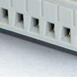


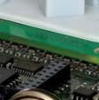
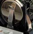
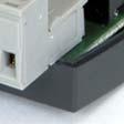


102 Battery location Grip the battery firmly with your fingers and lift it upwards until it rises from its holder. Press the new battery firmly down into place. Note that to preserve correct polarity, the battery can only be inserted the right way round Start-up wizard The start-up wizard is a function that can be activated inn "Configuration"/"System". See the section Activation of start-up wizard. If the wizard has been activated, the operator will access a number of menus at power-up. These menus contain certain operation parameters that should be b set. The wizard is useful when the controller is delivered pre-configuredd together with an air handling unit. After the controller has been configured, the manufacturer of thee air handling unit will activate the start-up wizard, which will help the operator to set setpoint values, running times etc. without having to log on. In the first menu, the languagee is chosen. Manual Corrigo E Ventilation, revision N Chapter 18 Other functions 102
Copyright AB Regin, Sweden, Corrigo E manual Ventilation application
 Copyright AB Regin, Sweden, 2013 Corrigo E manual Ventilation application DISCLAIMER The information in this manual has been carefully checked and is believed to be correct. Regin however, makes no warranties
Sauter flexotron 800 ventilation Manual
 Manual P100012082 Table of contents DISCLAIMER The information in this manual has been carefully checked and is believed to be correct. Fr. Sauter AG however, makes no warranties as regards the contents
Corrigo E - User Manual Ventilation
 Corrigo E - User Manual Ventilation DISCLAIMER The information in this manual has been carefully checked and is believed to be correct. Regin however, makes no warranties as regards the contents of this
SAUTER flexotron800 V2 Ventilation V3.3. manual P P
 SAUTER flexotron800 V2 Ventilation V3.3 manual 2/175 Content Content 1 Generell notes 9 1.1 Disclaimer 9 1.2 Trademarks 9 1.3 Safety information 9 1.3.1 Mandatory note 9 1.3.2 General note 10 1.4 Notes
WE TAKE BUILDING AUTOMATION PERSONALLY MANUAL CORRIGO
 WE TAKE BUILDING AUTOMATION PERSONALLY MANUAL CORRIGO Copyright AB Regin, Sweden, 2016 DISCLAIMER The information in this manual has been carefully checked and is believed to be correct. Regin however,
Copyright AB Regin, Sweden, Corrigo manual Ventilation application
 Copyright AB Regin, Sweden, 2014 Corrigo manual Ventilation application DISCLAIMER The information in this manual has been carefully checked and is believed to be correct. Regin however, makes no warranties
Corrigo E. Second generation which contains all applications and languages
 revision 05 2009 Corrigo E Second generation which contains all applications and languages The controllers in the Corrigo E series are intended for applications within heating, boiler and ventilation control
SAUTER flexotron 800 Ventilation application User Guide
 SAUTER flexotron 800 Ventilation application User Guide P100012091 1 Table of content P100012091 2 Table of content Table of content Table of content... 2 1 About this user guide... 4 2 About flexotron
Corrigo E - User Manual Heating
 Corrigo E - User Manual Heating DISCLAIMER The information in this manual has been carefully checked and is believed to be correct. Regin however, makes no warranties as regards the contents of this manual
Corrigo E Ventilation
 Corrigo E Ventilation Modbus communication guide Contains the most commonly used variables. Covers all versions of Corrigo E Ventilation from 3.2 The challenger in building automation Revision: 2 Date:
Corrigo E User Guide. Ventilation application
 Corrigo E User Guide Ventilation application Copyright AB Regin, Sweden, 2009 About this user guide This user guide covers all the models in the Corrigo E series used with the ventilation application.
C User manual
 C10...40 User manual Introduction COORIGO is a completely new range of controllers which has been designed to be easy to use and operate. The controllers have a display and built in panels for operation
Corrigo E - User Manual Heating
 Corrigo E - User Manual Heating User manual Corrigo E Heating... 3 1. About Corrigo E... 3 2. Installation and wiring... 5 3. Commissioning... 10 4. Functional description... 11 5. Display, LEDs and buttons...
Optigo OP10 Manual. Copyright AB Regin, Sweden, 2007 R E A D Y - S T E A D Y - G O
 O P T I G O Optigo OP10 Manual Copyright AB Regin, Sweden, 2007 R E A D Y - S T E A D Y - G O DISCLAIMER The information in this manual has been carefully checked and is believed to be correct. Regin however,
C-series Controllers for air handling systems
 C-series Controllers for air handling systems Corrigo, C-series, is a range of digital controllers for air-handling systems designed to be easy to use and operate, having a large capacity, and a high degree
Manual for the integration in BMS/GTC
 Manual for the integration in BMS/GTC Communication parameters MODBUS RTU and BACNET COMMUNICATION UTBS PRO-REG Software Version 3.6 EN ÍNDEX 1. GENERALITIES...2 1.1. Introduction...2 1.2. signals types...2
Topvex SX/C, Topvex TX/C Air Handling Unit
 Topvex SX/C, Topvex TX/C Air Handling Unit Operation and Maintenance Instructions Document in original language 131678 A003 GB Contents 1 Warnings...1 2 Product Description...2 2.1 Internal components...2
Operation and Maintenance Instructions
 Compact Air Handling Unit Operation and Maintenance Instructions Item# 415005 2015-06-23 Contents 1 Warnings...1 2 Product Description...1 2.1 Internal Components Topvex TR800-4000...1 2.2 Description
Topvex SR 09, 11, Topvex TR Compact Air Handling Units
 Topvex SR 09, 11, Topvex TR 09-15 Compact Air Handling Units Operation and Maintenance Instructions Document in original language 125594 A004 GB Copyright Systemair AB All rights reserved E&OE Systemair
Pre-programmed room controller with communication
 revision 01 2011 RC-C Pre-programmed room controller with communication RC-C is a complete pre-programmed room controller from the Regio Midi series intended to control heating and cooling in a zone control
Pre-programmed room controller with communication
 revision 02 2016 RC-C3 Pre-programmed room controller with communication RC-C3 is a complete pre-programmed room controller from the Regio Midi series intended to control heating and cooling in a zone
Pre-programmed room controller with communication and hidden setpoint
 revision 02 2016 RC-C3H Pre-programmed room controller with communication and hidden setpoint RC-C3H is a complete pre-programmed room controller from the Regio Midi series intended to control heating
Topvex SF02-SF12 Air Handling Unit
 Topvex SF02-SF12 Air Handling Unit Installation instructions Document in original language 130324 A004 GB Copyright Systemair AB All rights reserved E&OE Systemair AB reserves the rights to alter their
Corrigo E User Guide. Heating application
 Corrigo E User Guide Heating application Copyright AB Regin, Sweden, 2011 About this user guide This user guide covers all the models in the Corrigo E series used with the heating application. The document
TAP v2.10 Version Date: 6/12/13. Document Microprocessor Controller for Tempered Air Products
 Document 475595 Microprocessor Controller for Tempered Air Products Reference Guide for the Microprocessor Controller Please read and save these instructions. Read carefully before attempting to operate
Installation Guide. ECL Comfort 210, application A Table of Contents
 1.0 Table of Contents 1.0 Table of Contents... 1 1.1 Important safety and product information..................... 2 2.0 Installation... 4 2.1 Before you start.....................................................
AHU Control. Operating Instructions V5.00
 1177fil HHFlex C/R/P/S AHU Control Operating Instructions V5.00 Contents 1 SAFETY CONSIDERATIONS 5 1.1 General 5 1.2 Avoid Electrocution 5 1.3 Abbreviations used 5 2 CONTROLLER DESCRIPTION 6 2.1 Overview
EXcon zone control. Control for up to 4 individual zones _ fm. EXHAUSTO A/S Odensevej 76 DK-5550 Langeskov
 3005925_2018-02-05.fm EXcon zone control Control for up to 4 individual zones EXHAUSTO A/S Odensevej 76 DK-5550 Langeskov Tel. +45 65 66 12 34 Fax +45 65 66 11 10 exhausto@exhausto.dk www.exhausto.dk OJ-Air2
ENERGY LIGHT USER S GUIDE ENERGY LIGHT USER S GUIDE
 ENERGY LIGHT USER S GUIDE Release January 2001 CONTENTS 1.0 GENERAL CHARACTERISTICS... 4 1.1 MAIN CHARACTERIS TICS... 4 2.0 USER INTERFACE (CODE C5121230)... 5 2.1 DISPLAY... 5 2.2 MEANING OF THE LEDS...
ECL Comfort 110, application 116
 Operating Guide ECL Comfort 110, application 116 (valid as of software version 1.08) English version www.danfoss.com How to navigate? Adjust temperatures and values. Switch between menu lines. Select /
Master devices. Type X-AIR-ZMAS. Zone master module for up to 25 zone modules, with integral webserver and interfaces to higher-level systems
 X X testregistrierung Type Web server, also for mobile devices Zone modules Zone master module for up to 25 zone modules, with integral webserver and interfaces to higher-level systems X-AIRCONTROL zone
SECTION SEQUENCE OF OPERATIONS FOR HVAC CONTROLS
 SECTION 23 09 93 SEQUENCE OF OPERATIONS FOR HVAC CONTROLS PART 1 - GENERAL 1.1 SUMMARY A. This Section includes control sequences for HVAC systems, subsystems, and equipment. B. See Division 23 Section
N M AirControl AHU. Control manual
 N 10.63 M 03-2016 AirControl AHU Control manual EN CONTENTS PAGE 1 - MONITORING AND CONTROL 2 1.1 The program 2 1.2 The HMI terminal 2 1.3 The controller 4 1.4 Description of the air handling units 4
Feature Summary. I. System
 I. System A. Supports up to 60 VAV HVAC Units 1. Each HVAC Unit Can Support up to 59 VAV Boxes 2. Constant Volume Units Can Be Integrated With VAV Units 3. System Can Support Over 3000 Controllers B. Fill-in
Dryer Controller M720
 User Manual Dryer Controller M720 Hardware version 2.00 Software version 2.00 Manual M720 Dryer controller Page 1 of 60 Document history Preliminary version: - Created in April, 2009 Hardware Version 2.00,
Topvex SR 09, 11, Topvex TR Compact Air Handling Units
 Topvex SR 09, 11, Topvex TR 09-15 Compact Air Handling Units Installation instructions Document in original language 125593 A003 GB Copyright Systemair AB All rights reserved E&OE Systemair AB reserves
Room controllers with manual forced ventilation function
 revision 12 2016 RC-O Room controllers with manual forced ventilation function RC-O is a room controller from the Regio Mini series intended to control heating and cooling in a single zone. RC-O is a room
Reference Guide for Microprocessor Controller
 Document 483232 Microprocessor Controller for Energy Recovery Reference Guide for Microprocessor Controller Please read and save these instructions for future reference. Read carefully before attempting
ECL Comfort 210 controller, Remote Control Units ECA 30 / 31 and Application keys
 ECL Comfort 210 controller, Remote Control Units ECA 30 / 31 and Application keys Designed in Denmark Description ECL Comfort 210 controller series ECL 210 The ECL Comfort 210 is an electronic weather
SEQUENCE OF OPERATIONS
 SEQUENCE OF OPERATIONS DDC CONTROLLER: Controller with integral LCD readout for changing set points and monitoring unit operation. Provided with required sensors and programming. Factory programmed, mounted,
PRODUCT DATA COMFORT 450 BY NILAN. Ventilation & passive heat recovery. Passive heat recovery. < 450 m 3 /h
 PRODUCT DATA COMFORT 40 BY NILAN Ventilation & passive heat recovery Domestic Passive heat recovery Ventilation < 40 m /h COMFORT 40 Product description The Comfort 40 is an energy-efficient ventilation
Reference Guide for Microprocessor Controller
 Document 483586 Microprocessor Controller for Dedicated Outdoor Air System Reference Guide for Microprocessor Controller Please read and save these instructions for future reference. Read carefully before
Room controller. RC is a room controller from the Regio Mini series intended to control heating and cooling in a single zone.
 revision 12 2016 RC Room controller RC is a room controller from the Regio Mini series intended to control heating and cooling in a single zone. RC is a room controller in the Regio series. The controller
PRODUCT DATA COMFORT 600 BY NILAN. Ventilation & passive heat recovery. Passive heat recovery. < 800 m 3 /h
 PRODUCT DATA COMFORT 00 BY NILAN Ventilation & passive heat recovery Domestic Passive heat recovery Ventilation < 800 m /h COMFORT 00 Product description The Comfort 00 is an energy-efficient ventilation
TC-9102 Applications
 Application Note January 7, 2004 APPLICATION NOTE TC-9102 Applications Configuring TC-9102 Applications...3 Introduction... 3 Key Concepts... 4 TC-9102 Controller... 4 Control Modes...8 Procedure Overview...
user s manual VUBMG102
 user s manual CONTROL SYSTEM DHP-R VUBMG102 2 Danfoss VUBMG102 Contents 1 Introduction... 5 2 Functional description... 7 2.1 Heating... 7 2.1.1 Primary supply temperature...7 2.1.2 Integral control...7
NA G µair CONNECT 2
 NA 9.41 G 7-216 µair CONNECT 2 Control manual EN CONTENTS PAGE 1. GENERAL INFORMATION 2 2. COMPONENTS 3 2.1 On the front: 3 2.2 On the rear: 4 3. MENU TREE 7 4. ACCESS LEVEL (menu 8) 1 5. CONFIGURING
ModSync Sequencing System Installation & Operation Manual. For use with Fulton Steam Boilers.
 ModSync Sequencing System Installation & Operation Manual For use with Fulton Steam Boilers. Revision 3.0 8/21/2008 - 2 - Table of Contents Introduction Page 4 Features Page 4 Sequence of Operation Page
ggg Air Handling Unit RT 700/1000S-EC-RS INSTALLATION OPERATION & CONTROL PANEL MAINTENANCE & SERVICE
 ggg INSTALLATION DESIGN & TECHNICAL INFORMATION OPERATION & CONTROL PANEL MAINTENANCE & SERVICE Exhaust air filter, article No: Q4871 Supply air filter, article No: Q4872 June 2013 1 CONTENTS Page Installation
Control equipment. Contact, Overview, Index. Guideline heating and cooling. Plexus. Professor / Professor Plus. Premum / Premax.
 Contact, Overview, Index Guideline heating and cooling Plexus Professor / Professor Plus Premum / Premax Architect Polaris I & S Plafond Podium Celo Cabinett Capella Carat Fasadium Atrium / Loggia Drypac
QAF64.2-J QAF64.6-J. Frost detector. for use on the air side
 s Frost detector for use on the air side QAF64.2-J QAF64.6-J With active capillary tube sensing element for acquiring the lowest temperature within a range of 0 15 C With startup function Operating voltage
Odyssey. issue 01c. system manual
 dyssey issue 01c system manual SYSTEM MANUAL Table of Contents Technical Specification 1 Summary of Features 2 General Description 3 Control ptions 4 Description of Main Features 5 Control Schemes 6 Installation
Instructions for the fan motor control system with integrated wiring terminals SILVER C
 Instructions for the fan motor control system with integrated wiring terminals SILVER C 1. General The motor control system is used for controlling the type EC, 0.41-10 kw fan motors in the SILVER C units.
Capacity controller for water chiller AK-CH 650
 Capacity controller for water chiller AK-CH 650 Menu operation via AKM Menu list This menu function can be used together with system software type AKM. The description is divided up into function groups
EBC20. Instructions for fitting, installation and operation. Read and save these instructions!
 EBC20 UK Instructions for fitting, installation and operation Read and save these instructions! 2 3002878 EBC20 UK 290415 1. Product information............................................... 4 1.1 Delivery.............................................................
Modular Standard HP Chiller 1/4 screw compressor with Carel driver
 Program for pco¹ pco 2 and pcoc Modular Standard HP Chiller 1/4 screw compressor with Carel driver Manual version 1.0 25 September 2003 Program code: FLSTDmMSDE Do we want you to save you time and money?
Weather compensated flow temperature control of heating and boiler systems
 Instructions ECL Comfort 110 Application 130 Weather compensated flow temperature control of heating and boiler systems User guide, Installation & Maintenance DH-SMT/DK VI.KT.G3.02 Danfoss 06/2008 How
User Manual. Dryer Controller M720
 User Manual Dryer Controller M720 Hardware version 1.00 Software version 1.00 Preliminary version Manual M720 Dryer controller Page 1 of 42 Document history Preliminary version: - Created in April, 2009
ECL Comfort 210 controller, Remote Control Units ECA 30 / 31 and Application keys Designed in Denmark
 ECL Comfort 210 controller, Remote Control Units ECA 30 / 31 and Application keys Designed in Denmark Description ECL Comfort 210 controller series The ECL Comfort 210 is an electronic weather compensated
Operating Guide. ECL Comfort 210 / 296 / 310, application A247 / A Table of Contents
 1.0 Table of Contents 1.0 Table of Contents... 1 1.1 Important safety and product information..................... 2 2.0 Installation... 6 2.1 Before you start.....................................................
PRODUCT DATA COMFORT 5000 BY NILAN. Ventilation & passive heat recovery. Passive heat recovery. < 5300 m 3 /h
 PRODUCT DATA COMFORT 5000 BY NILAN Ventilation & passive heat recovery Commercial Passive heat recovery Ventilation < 5300 m 3 /h COMFORT 5000 The Comfort 5000 is a ventilation unit suitable for central
ER65-DRW Controller. Heating Applications. Product Bulletin. Heating Controller
 PB_ER65-DRW_ 202 ER65-DRW Controller Heating Applications Product Bulletin The controller is a digital device for domestic or residential heating units. It covers water and air heating applications. All-in-one
0 C to 50 C ( 32 F to 122 F ) 0% to 95% R.H. non-condensing. 30 to 95% R.H. Dry contact across terminal BI1, BI2 & UI3 to Scom
 0% to 95% R.H. non-condensing. 30 to 95% R.H. Dry contact across terminal BI1, BI2 & UI3 to Scom") Viconics VT7350 Series PIR Ready Fan-coil Controllers General The VT7350 series are PIR Ready low-voltage microprocessor-based fan-coil controllers. Models are available controlling single speed and multi-speed
Viconics VT7350 Series PIR Ready Fan-coil Controllers General The VT7350 series are PIR Ready low-voltage microprocessor-based fan-coil controllers. Models are available controlling single speed and multi-speed
EKC 347 Liquid Level Controller REFRIGERATION AND AIR CONDITIONING. Manual
 EKC 347 Liquid Level Controller REFRIGERATION AND AIR CONDITIONING Manual Contents Introduction...3 Valve compatibility...3 Features...3 Application examples...3 Ordering...3 Operating the EKC 347...4-5
ECL Comfort 300 / V a.c. and 24 V a.c.
 Data sheet ECL Comfort 300 / 301 230 V a.c. and 24 V a.c. Application The ECL Comfort 300 / 301 is an electronic temperature controller which can be loaded with selected applications by means of an ECL
SECTION SEQUENCE OF OPERATIONS FOR HVAC CONTROLS
 PART 1 - GENERAL SECTION 23 09 93 SEQUENCE OF OPERATIONS FOR HVAC CONTROLS 1.1 SUMMARY A. This Section includes control sequences for HVAC systems, subsystems, and other equipment. B. See Division 23 Section
BLAUAIR AUTOMATIC CONTROL SYSTEM
 BLAUAIR AUTOMATIC CONTROL SYSTEM S30 (KVENT, TH-TUNE) S31 (KVENT) S32 (KVENT, PGDE) EN USER S MANUAL CONTENTS Safety requirements... 3 Purpose... 4 Technical data... 5 Installation and set-up... 6 Control...
Topvex SR03, SR04, SR06 Compact Air Handling Unit
 Compact Air Handling Unit GB GB Corrigo ver. no. 1.2-1-00 Manufacturer Our products are manufactured in compliance with applicable international standards and regulations. Systemair AB Industrivägen 3
SAVE VSR 150/B. Installation and Service. Document in original language A001
 SAVE VSR 150/B Installation and Service Document in original language 211456 A001 GB Copyright Systemair UAB All rights reserved E&OE Systemair UAB reserves the rights to change their products without
Rooftop Thermostat Controller Specification and Installation Instructions. Model TRT2422
 ºF / º C Rooftop Thermostat Controller Model TRT2422 Description The TRT2422 is a combination controller and thermostat with a built-in scheduler, which is designed for simple and accurate control of single
Air Handling Unit. REC Temovex Blue 4 NEW! Experts on indoor climate in low-energy houses
 NEW! REC Temovex Blue 4 Experts on indoor climate in low-energy houses REC Temovex Blue 4 Third generation of our Temovex units! - Dual counterflow heat exchangers with over 9% efficiency * - SFP < 1,
Smart thermostat with Humidification/De-humidification control
 x Smart thermostat with Humidification/De-humidification control Enter/Confirm Scroll Right = Increase Left = Decrease Back/Cancel TABLE OF CONTENTS Everyday Use 1. Adjusting Temperature...3 2. Adjusting
ECL Comfort V a.c. and 24 V a.c.
 Data sheet ECL Comfort 300 230 V a.c. and 24 V a.c. Application The ECL Comfort 300 is an electronic temperature controller which can be loaded with selected applications by means of an ECL Card. The ECL
Technician manual
 Air Handling Unit Temovex Blue 4 Technician manual 1.6-1-01 INSTALLATION OPERATION & CONTROL Exhaust air filter, article No: G10125 Supply air filter, article No: G10126 1 CONTENTS Air Handling Unit Temovex
CONTROLS MANUAL For all Innovent and Valent air handling products
 CONTROLS MANUAL For all Innovent and Valent air handling products TABLE OF CONTENTS TABLE OF CONTENTS IMPORTANT INFORMATION Safety information...................................................................................
Safety & Installation Instructions
 Model 8800 Universal Communicating Thermostat Safety & Installation Instructions READ AND SAVE THESE INSTRUCTIONS Table of contents Installation Installation location recommendations... 2 Thermostat mounting...
Operating instructions
 Operating instructions Control unit - CGL Zone 0.0 C Friday 3/0/08 : 6 Wolf GmbH Postfach 380 D-84048 Mainburg Tel. +49 (0)875/74-0 Fax +49 (0)875/74600 Internet: www.wolf-heiztechnik.de Document no.:
THX-DL Data Logger USER & INSTALLATION MANUAL V
 THX-DL Data Logger USER & INSTALLATION MANUAL V1.2012 www.thermomax-refrigeration.com Contents PRESENTATION Summary of Features 2 INSTALLATION Safety Precautions 4 THX Unit 4 Sensors 4 Alarm Relay 4 Power
ECL Comfort 110, application 130
 Operating Guide ECL Comfort 110, application 130 (valid as of software version 1.08) English version www.danfoss.com How to navigate? Adjust temperatures and values. Switch between menu lines. Select /
ECL Comfort V a.c. and 24 V a.c.
 230 V a.c. and 24 V a.c. Description and application The controller is designed for easy installation: one cable, one connector. The controller has a customdesigned display with backlight. For a quick
FUNCTIONAL DESIGN SPECIFICATION
 Issue Date: Issued To: Revision: FUNCTIONAL DESIGN SPECIFICATION Specification Number: SP-XXXX Company Name Signature Date Issued By: Manutec Ltd. Approved By: Approved By: Approved By: Approved By: Authorised
USER'S MANUAL PU SENS 01 (A11) PU SENS 01 (A19) Sensor Control Panel
 PU SENS 01 (A19) Sensor Control Panel") USER'S MANUAL PU SENS 01 (A11) PU SENS 01 (A19) Sensor Control Panel PU SENS 01 CONTENTS Safety requirements... 3 Purpose... 4 Technical data... 4 Overall dimensions [mm]... 4 Mounting and set-up... 5
USER'S MANUAL PU SENS 01 (A11) PU SENS 01 (A19) Sensor Control Panel PU SENS 01 CONTENTS Safety requirements... 3 Purpose... 4 Technical data... 4 Overall dimensions [mm]... 4 Mounting and set-up... 5
1.0 Digital Controller
 1.0 Digital Controller...1 1.1 Display Function Keys...1 1.2 Thermostat Display...2 1.3 Controller hardware input output points... 4 2.0 Sequence of Operation...5 2.1 States of Operation...5 2.2 Modes
Digital Precise Air Control - DPAC
 Digital Precise Air Control - DPAC Mode Enable Sensor Options The temperature of this sensor will determine if the unit is in heating, cooling or vent mode during Occupied operation. The following options
PRODUCT DATA COMBI 300 POLAR BY NILAN. Ventilation with passive & active heat recovery. Active heat recovery. Passive heat recovery.
 PRODUCT DATA COMBI 300 POLAR BY NILAN Ventilation with passive & active heat recovery Domestic Passive heat recovery Active heat recovery Ventilation < 350 m 3 /h Comfort heating Comfort cooling COMBI
Replaceable LED modules. Sleep or unattended mode. Auto-silence and auto-acknowledge
 Replaceable LED modules 11 Alarm Sequences as per ISA-18.1 standard Each channel/window fully field programmable RS232 or RS485 MODBUS-RTU communication Repeat relay for each window and multifunction relays
Natural Ventilation Controller with 24vDC drive NVC-1204
 Natural Ventilation Controller with 24vDC drive NVC-1204 BACnet Enabled C-038 08/16 FEATURES SPECIFICATION > 24V DC supply > Native BACnet communications > Master/Slave grouping (shared information) >
LMV52 Control. Specifications. Document No. LV February 3, Product Description. Sample Specification
 LMV52 Control Product Description February 3, 2017 The LMV52 is a microprocessor-based burner management system with matching system components for the control and supervision of forced draft burners.
PRELIMINARY EDITION
 3 131 PRELIMINARY EDITION 14.01.2003 Synco 700 Heating Controllers Heating controller for medium-size and large buildings. The is used as a heating circuit or primary controller. The controller is supplied
UNIFIED FACILITIES GUIDE SPECIFICATIONS
 USACE / NAVFAC / AFCEC / NASA UFGS-23 09 93 (November 2015) ----------------------------- Preparing Activity: USACE Superseding UFGS-23 09 23 (May 2011) UNIFIED FACILITIES GUIDE SPECIFICATIONS References
Sensor Control Panel
 USER S MANUAL PU SENS 01 Sensor Control Panel V55-6EN-03(SENS).indd 1 18.08.2015 10:37:16 2 PU SENS 01 CONTENTS Safety Requirements 2 Main Technical Data 3 Control Panel Mounting 3 Control Panel Operation
CommStat 6. Controller for Redundant HVAC Systems PRODUCT DATA SHEET
 CommStat 6 Controller for Redundant HVAC Systems PRODUCT DATA SHEET General Description The CommStat 6 HVAC controller is designed for controlling up to six redundant air conditioners in an E-House or
Emerson Inspire 1HDEZ Installation Instructions. Thermostat/Interface Equipment Control TROUBLESHOOTING
 Emerson Inspire 1HDEZ-1521 Installation Instructions Thermostat/Interface Equipment Control TROUBLESHOOTING FAILURE TO READ AND FOLLOW ALL INSTRUCTIONS CAREFULLY BEFORE INSTALLING OR OPERATING THIS CONTROL
READ AND SAVE THESE INSTRUCTIONS
 XXXXXXX-0 EN 1904 READ AND SAVE THESE INSTRUCTIONS BASIC-PLC CONTROLLER MANUAL For all Condair desiccant dryer with equipped with Basic- PLC valid from version: PLC-35/PLC-45 18.04.03 Dehumidification
ETO 2 - Controller for ice and snow melting
 ETO 2 - Controller for ice and snow melting Advantages Simple adjustment knob with two functions Illuminated display where you can easily see the temperature status and other values Controls both pumps
VAV Thermostat Controller Specification and Installation Instructions. Model TRO24T4XYZ1
 Model TRO24T4XYZ1 Description The TRO24T4XYZ1 is a combination controller and thermostat. The VAV Thermostat Controller is designed for simple and accurate control of any variable air volume box in a number
ECL Comfort 310 controller, Remote Control Units ECA 30 / 31 and Application keys
 ECL Comfort 310 controller, Remote Control Units ECA 30 / 31 and Application keys Designed in Denmark Description ECL Comfort 310 controller series ECL 310 The ECL Comfort 310 is an electronic weather
flexotron800 SAUTER flexotron800 V2 Heating user program User guide P P /36 P
 SAUER V2 Heating user program User guide /36 2/36 Contents Contents About this user guide 5. Disclaimer 5.2 rademark 6.3 Safety information 6.3. Compulsory note 6.3.2 General note 6.4 Information on using
RVL471. Heating controller. G2524en. Installation Instructions. 1 Installation. 2 Commissioning
 G2524en Heating controller Installation Instructions RVL471 1 Installation 1.1 Place of installation In a dry room, e.g. the boiler room Mounting choices: In a control panel (on the inner wall or on a
DX-9100 Applications from Engineering Services
 System 9100 Technical Manual 636.4 Application Examples Section Technical Bulletin Issue Date 0896 DX-9100 Applications from Engineering Services Introduction Page 3 Overview 3 Air Handling Unit Applications