AHU Control. Operating Instructions V5.00
|
|
|
- Allyson Mason
- 5 years ago
- Views:
Transcription
1 1177fil HHFlex C/R/P/S AHU Control Operating Instructions V5.00
2 Contents 1 SAFETY CONSIDERATIONS General Avoid Electrocution Abbreviations used 5 2 CONTROLLER DESCRIPTION Overview Power Supply Battery Indications Mapping of Inputs/Outputs Technical data Common Data Controller Communication Casing Inputs Outputs External display TCP/IP port 8 3 HUMAN MACHINE INTERFACE E-DSP External display unit Overview Log in Access levels external display Web panel Connection to the unit Login Screen Overview Screen Actual/Setpoint screen Alarm Status screen Inputs/Output screen Time Program screen Settings screen Manual/Auto screen Factory Screen Real Time Charts 17 4 HHFlex BASIC CONTROL FUNCTIONS Temperature Control Temperature control in occupied mode Supply air temperature control Economy mode based on OAT Room air temperature control Extract air temperature control Temperature control in non-occupied mode Fan speed control Fixed Fan Speed Control High / low speed operation Air Flow Control High / low air flow operation 21 2
3 4.3.5 Supply Duct Pressure Control Supply and exhaust Duct Pressure Control Indoor Air Quality Control Heat Recovery Monitoring Low Supply Air Temperature Monitoring High Supply Air Temperature Monitoring Frost Protection without Pre-Heating Filter Monitoring equipped with a pressure differential switch Fout! Bladwijzer niet gedefinieerd. 4.1 Filter Monitoring equipped with a pressure sensor Occupancy Management Stand alone mode Internal Clock Operation Time Extension Remote mode Building Fire Management 24 5 HHFlex OPTIONAL CONTROL FUNCTIONS Air Dampers Hot-water reheating Coil Water Coil Frost Protection Warm Up at Unit Start Up Unit Frost Protection Chilled-water Cooling Coil Temperature Control Change-over water Coil for Heating and Cooling Heat/Cool Thermostat Temperature Control Water Coil Frost Protection Warm Up at Unit Start Up Unit Frost Protection Electrical reheating Coil Temperature Control Overheating protection Cool down at unit stop Electrical pre-heating Coil Heat Recovery Frost Protection Overheating protection Cool down at unit stop Hot water pre-heating Coil Heat Recovery Frost Protection Water Coil Frost Protection Warm Up at Unit Start Up Unit Frost Protection Direct-expansion coil Condensing unit/reversible unit with staged capacity Condensing unit/reversible unit with variable capacity Water pump anti-blocking system Recirculation air damper Fast building temperatue warm-up/cool-down before an occupied period Operation of chilled beams during unoccupied periods Heat pump defrost 32 3
4 5.17 Minimum/maximum room temperature in an unoccupied period Humidification control Description control algorithm Default settings for relative humidity control Dehumidification control Description control algorithm Default settings for relative humidity control 35 6 DIAGNOSTICS & TROUBLESHOOTING General Displaying Alarms E-DSP External display unit Web Panel Alarm report Resetting Alarms Alarms List 37 7 BUS COMMUNICATION General Modbus Communication Settings Modbus type Modbus functions Max. 47 registers Communication limits Scale factor Modbus Register list BACnet IP register list ANNEX 1 - BACNET PROTOCOL IMPLEMENTATION AND CONFORMITY ANNEX 2 - SECURITY SETTINGS IN THE WEB BROWSER AND JAVA CONTROL PANEL Problems showing updated measured values The web pages split into different windows Popup windows, JavaScript and Cookies Export function in the historical chart window 63 The manufacturer reserves the right to change the specifications without prior notice. Graphics and photos are for illustration purposes only and not contractually binding. 4
5 1 SAFETY CONSIDERATIONS 1.1 General Installation, start-up and servicing of equipment can be hazardous if certain factors particular to the installation are not considered: operating pressures, presence of electrical components and voltages and the installation site (elevated plinths and built-up up structures). Only properly qualified installation engineers and highly qualified installers and technicians, fully trained for the product, are authorized to install and start-up the equipment safely. During all servicing operations all instructions and recommendations which appear in the installation and service instructions for the product, as well as on tags and labels fixed to the equipment and components and accompanying parts supplied separately, must be read, understood and followed. Apply all standard safety codes and practices. Wear safety glasses and gloves. Use the proper tools to move heavy objects. Move units carefully and set them down gently. 1.2 Avoid Electrocution Only personnel qualified in accordance with IEC (International Electrotechnical Commission) recommendations may be permitted access to electrical components. It is particularly recommended that all sources of electricity to the unit be shut off before any work is begun. Shut off the main power supply at the main circuit breaker or isolator. 1.3 Abbreviations used AHU AI AO CHO CWC DI DO EAT HWC IAT OAT RAM Air Handling Unit Analog Input Analog Output Change Over Coil Cold Water Coil Digital Input Digital Output Extract Air Temperature Hot Water Coil Inlet Air Temperature (Sensor placed just before heat recovery exchanger) Outdoor Air Temperature Random Access Memory (volatile memory) 5

6 2 CONTROLLER DESCRIPTION HHFlex controller is an electronic control system to regulate Air Handling Units. The control system consists of two controllers which are described hereafter. 2.1 Overview Controller Overview Port 2 and TCP/IP are only available on the main controller 2.2 Power Supply Each controller operates at 24 VDC and has a power consumption of 4 VA (without load, without display). In the event of a power supply interrupt, the unit restarts automatically without the need for an external command. However, any faults active when the supply is interrupted are saved and may in certain cases prevent unit from restarting. 2.3 Battery The resources and the program are stored in RAM. To ensure that they are not lost and that the hardware clock continues to run when there is a power failure, the controller is equipped with a buffer battery. The buffer time is at least 5 years. The buffer battery is a 3V lithium battery (CR2032). The battery voltage is monitored. When battery is low the P/B Indication LED lights red. 2.4 Indications The upper left corner of each controller contains four LEDs which give the status indication of the controller. Designation Colour Description P1 RxTx Yellow/ Green Port 1: Receiving/transmitting P2 RxTX TCP/IP P/B Yellow/ Green Green/ Yellow Green/ Red Port 2: Receiving/transmitting Fixed green: Link Flashing green: Traffic Flashing yellow: Identification Power supply / Low battery level 6
7 2.5 Mapping of Inputs/Outputs 7

8 2.6 Technical data Common Data Controller Supply voltage 24 VAC ±15%, Hz or VDC Power consumption 4 VA (without load, without display) BTL approval EXOreal or later +C output +24 V DC, 0,15 A, short-circuit proof Operating system EXOreal C Battery backup Memory and real-time clock, at least 5 years Ambient temperature 0 50⁰C Storage temperature ⁰C Relative humidity (non-condensing) Max. 95% Dimensions (WxHxD) 149 x 121 x 60 mm Din controller width 8 ½ EMC emissions and immunity standard: This product conforms to the requirements of the EMC Directive 2004/108/EC through product standards EN and EN RoHs: This product conforms to the Directive 2011/65/EU of the European Parliament and of the Council Communication Serial TCP Modbus Speed (Port 1 and Port 2) RS485 (EXOline or Modbus with automatic detection/change over) EXOline-TCP, BACnet/IP, Modbus/IP (requires EXOreal or later) 8 bits, 1 or 2 stop bits. Odd, even (Fs) or no parity. adjustable bps Casing Protection class Mounting Plastic IP20 DIN-rail mounting or mounting in cabinet Polycarbonate, PC Inputs Analogue inputs, AI Digital inputs, DI Universal inputs. UI 0(4) 20 ma, 0 10 V, mv, PT-1000, DIN Ni1000, LGNi1000, 12 bits A/D Potential-free contact, 24 V DC, configurable for pulse input AI or DI (see above) Outputs Analogue outputs, AO 0 10 V DC, 5 ma, 12 bit D/A, short circuit-protected Digital outputs, DO Mosfet 24 V AC/DC, 2 A. Max 8 A in total. 24 V DC output 0.15 A, short circuit-protected External display Models Connection Max. cable length E3-DSP, ED9200 or ED-RU 4P4C modular connector. 100 m TCP/IP port Connection RJ45, 10Base-T/100Base-TX auto-negotiation Cable length Max. 100 m (min Cat 5) Power consumption + 1 VA in addition to basic consumption. 8


9 3 HUMAN MACHINE INTERFACE 3.1 E-DSP External display unit 3.2 Overview The display menu system is accessed using seven buttons: The LEDs have the following functions: Designation Function Colour There are one or more unacknowledged alarm(s) Flashing red There are one or more remaining, acknowledged alarm(s) You are in a dialogue box where it is possible to switch to change mode Change mode Fixed red Flashing yellow Fixed yellow 3.3 Log in The standard passwords are 3333 for basic level with the lowest access (guest) and 2222 for level giving more access (operator). Menu tree external display 9
10 3.4 Menu tree external display DEFAULT SCREEN ACTUAL / SETPOINTS SOFTWARE VERSION ACTIVATE OUT OF HOUR TEMPERATURE OUT OF HOURS OVERRIDE TIME OUTDOOR TEMPERATURE HUMIDITY DE-HUMIDITY AIR VOLUME / FANSPEED SUPPLY FAN INLET HUMIDITY SUPPLY HUMIDITY INLET HUMIDITY SUPPLY HUMIDITY ROOM HUMIDITY SUPPLY TEMPERATURE ROOM TEMPERATURE EXTRACT TEMPERATURE DUCT PRESSURE SUPPLY DUCT EXHAUST FAN ROOM HUMIDITY EXTRACT HUMIDITY INDOOR AIR QUALITY EXHAUST DUCT EXTRACT HUMIDITY FILTER SENSOR SUPPLY HEAT RECOVERY UNIT EXHAUST CONFIGURATION RUNMODE END ALARM LOG TEMPERATURE CONTROL INPUTS/ OUTPUTS MAIN CONTROLLER HUMIDITY CONTROL TIME SCHEDULE RUN SCHEDULE SLAVE 1 CONTROLLER FANCONTROL LOW SPEED SLAVE 2 CONTROLLER OUTDOOR COMPENSATION NIGHTCOOLING NIGHTCOOLING RECIRCULATION FIRE ALARM SETTINGS PUMPTEST HOLIDAYS SETTINGS RUNTIME ADJUST TIME/ DATE ELECTRIC FROST HEATER ELECTRIC BOOSTER HEATER COMMUNICATION GATEWAY AHU ON MODBUS CONFIG EXOLINE ADDRES HEAT DEMAND BACNET IP CONFIG CURRENT IP ADDRESS COLD DEMAND ALARM SETTINGS PRESSURE FAILURE SUPPLY FAN SUBNETMASK RELEASE DX SUPPLY TEMPERATURE LOW EXTRACT FAN GATEWAY PUMP PREHEATER FILTER SENSOR HIGH SUPPLY DNS PUMP BOOSTER HEATER PUMP COOLER/ CHANGE-OVER MANUAL-AUTO MAIN CONTROLLER EXHAUST PUMP RUN-A- ROUND COIL SLAVE 1 CONTROLLER END HUMIDIFIER SLAVE 2 CONTROLLER FACTORY TYPE AND SERIAL NR. MAIN CONTROLLER SLAVE 1 CONTROLLER SLAVE 2 CONTROLLER ACCES RIGHTS LOG ON LOG OFF CHANGE PASSWORD 10
11 3.5 Access levels external display VISIBLE FOR EVERYONE NO CHANGES CAN BE MADE VISIBLE FOR EVERYONE USERS LOGGED IN AS GUEST (3333) OR HIGHER CAN MAKE CHANGES VISIBLE FOR EVERYONE USERS LOGGED IN AS OPERATOR (2222) OR HIGHER CAN MAKE CHANGES ONLY VISIBLE FOR USERS LOGGED IN AS FACTORY 3.6 Web panel Access to the data of HHFlex can be done thanks to a PC with internet explorer including Java. 3.7 Connection to the unit To access the HHFlex controller, enter the IP address of the unit in the address bar of the web browser. The controller has two IP addresses, one service IP address and one user IP address. The controller is working in service IP address mode when Digital Input DI7 of the main controller is closed (connect +24VDC to DI7) and is working in user IP address mode when DI7 is open. The default service IP and user IP address of the unit is The user IP address can be changed in the Actual/ Setpoint menu when operating in service IP address mode or with the E-DSP under Service => Communication The service IP address can t be changed. The IP address of the PC, directly connected to the unit should be in the same group as the IP address of the unit ( *.*). Minimum web browser configuration: Internet explorer Java platform version 8 is required for controllers with software version 1.10 or higher (in the control panel untick the option that allows storing temporary internet files and use a direct connection). Flash player plug-in 7.0 or later installed For more information on the web browser and Java platform contact your network administrator. Many users can be connected at the same time. There is no priority between users; last modification is taken into account. 3.8 Login Screen There are three login levels: Basic level with the lowest access, password guest Level giving more access, password operator Level with full access, for manufactory purpose only 11

12 3.9 Overview Screen Displays the process diagram and status of the unit. This is a read only folder. No settings can be made Actual/Setpoint screen Displays relevant setpoints and actual values. All values written in blue can be changed. As soon as a value has been changed and you have pressed enter, the value is downloaded to the HHFlex controller. Users logged in as Guest can only make changes in the left column. Users logged in as Operator can make changes in both columns. 12


13 3.11 Alarm Status screen Shows actual Alarms and Status of the unit. Alarms can acknowledged, blocked or unblocked Users logged in as Guest or Operator can make changes BE CAREFUL: Blocking Alarm can lead to unsafe situations Inputs/Output screen Shows actual values for all inputs and outputs. This is a read only folder. No settings can be made. 13

14 3.13 Time Program screen Here you can set the time programs: Run schedule. Low Speed schedule. (Run schedule must be active) Nightcooling schedule. Recirculation schedule. Pump test schedule. Holiday program All values written in blue can be changed by users logged in as Guest or Operator. As soon as a value has been changed and you have pressed enter, the value is downloaded to the HHFlex controller. The day begins at hours and ends at hours 14


15 3.14 Settings screen All values written in blue can be changed by users logged in as Operator. As soon as a value has been changed and you have pressed enter, the value is downloaded to the HHFlex controller. Only users logged in as Operator can make changes BE CAREFUL: Bad PID parameters can lead to unstable control Manual/Auto screen For testing purpose only all functions can manually set here to a certain value. Only users logged in as Operator can make changes BE CAREFUL: All settings which are made here will be executed. Protections like frost protection, max temperature electric heater and minimum airflow electric heater will be ignored. 15

16 3.16 Factory Screen For manufactory purpose only, data can be read but changed only by manufactory 16
17 3.17 Real Time Charts The link Trend starts the option to handle real-time charts in de website. The operator may use the Copy to clipboard command in order to copy the values currently displayed in the diagram (as tab-separated text, TSV). This text may then be pasted into, for instance, Excel. When the Copy to clipboard command is executed, a dialogue window is opened in which the resolution for the values about to copy can be selected. The following alternatives are available: 1 hour, 15 minutes, 1 minute and 5 seconds. The most suitable alternative is pre-chosen in consideration to the current interval in the diagram. When copying takes place, a title row is first created, followed by a row for every period for the time range and signals currently displayed in the diagram. The title row consists of a date, following by the titles of the various signals with units (within parenthesis). The additional rows consist of a time, followed by values for the various signals (with the configured amount of decimals but with no units) Date, times and decimal points are written in a national format, in accordance with the settings of the computer running the web browser. For time periods whose values are missing (or are not applicable), the value will be empty strings. Example: 23 jul 2014 Measured ( C) Measured ( C) Command (%) 09:57:00 21,5 19, :58:00 21,5 19, :59:00 21,5 19, :00:00 22,1 18, :01:00 22,0 18, :02:00 22,0 18, :03:00 22,0 18, :04:00 22,0 18, :05:00 22,0 18, :06:00 22,8 18,
18 4 HHFlex BASIC CONTROL FUNCTIONS 4.1 Temperature Control Room Temperature Hysteresis set by user Threshold set by Advanced User Hysteresis set by user Max. Cooling Free Cooling Off Max. Heating HR + Gradual Cooling Free Cooling Heat Recovery (HR) HR + Gradual Heating function of extract air temp Unoccupied Mode Occupied Mode Temperature control in occupied mode The HHFlex AHU controller can control either: the supply air temperature or the extract air temperature (cascade control of the supply air temperature) or the room air temperature (cascade control of the supply air temperature) The selection of the temperature controlled is made in the menu Configuration (menu Actual/Setpoint). To save energy, HHFlex controller offers the possibility to correct the setpoint based on the actual outdoor temperature. All setpoints are configurable in the menu Actual/Setpoint Supply air temperature control To activate this function select supply air temp. in the configuration menu. If OAT correction is selected there is compensation on the supply air temperature according the graph: SAT setpoint Y1 30 C Y2 22 C Y3 14 C C X1 X2 X3 OAT C 4.2 Economy mode based on OAT If the option Eco mode on Outdoor Temp is selected in the configuration menu (Actual/Setpoint) then mechanical heating/cooling can be disabled between 2 OAT values. Heat recovery device can also be stopped during this economy mode thanks to a configuration parameter. 18
19 4.2.1 Room air temperature control To activate this function select room temp. in the configuration menu If OAT correction is selected there is outdoor compensation on setpoint according the graph: RAT setpoint correction Y3 +2 K Y2 0 K Y1-2 K C X1 X2 X3 OAT C 19
20 4.2.2 Extract air temperature control To activate this function select Extract air temp. in the configuration menu If OAT correction is selected there is outdoor compensation on setpoint according the graph: Y3 +2 K EAT setpoint correction Y2 0 K Y1-2 K X1 X2 OAT C X3 The temperature is fine controlled only in occupied mode. In non-occupied mode, the unit is normally stopped but can be restarted for special functions described hereafter Temperature control in non-occupied mode Minimum Room Temperature Surveillance: Restart unit with mechanical heating if room temperature drops below threshold. Maximum Room Temperature Surveillance: Restart unit with mechanical cooling if room temperature rises above threshold. These functions are available only for control on room temperature or when night cooling is selected. To set the parameters for this function, go to the menu Actual/Setpoint Room Temperature. Summer Night Ventilation Free Cooling: Restart unit to pre-cool the room only with outdoor fresh air. These function is available only when night cooling is selected in the configuration menu. To set the parameters for this function, go to the menu Actual/Setpoint Nightcooling. 20
21 4.3 Fan speed control Different options for ventilation control can be selected: Fixed fan speed control (low or high speed) Air flow control (low or high airflow) Supply duct pressure control Supply and exhaust duct pressure control Indoor air quality control Fixed Fan Speed Control To activate this function, set Fan control to Fixed (on/off) or Fixed (high/low) in the configuration menu. Setpoints for this function are available in the menu Actual/Setpoint. Supply and extract fan are On or Off. Supply and extract air volumes or pressures are not closed loop controlled and vary with airside resistance. This setting is mainly intended for commissioning, inspection and maintenance, but can also be selected in the fan speed control menu. In the frequency inverter the maximum motor speed limit is set on the design fan speed x To run the unit on design duty, the setpoints for fixed fan speed are set to 95% High / low speed operation For certain applications two different setpoints fixed speed operation can be selected within the controller. The setpoints for high/low speed will be the rated speed of the fans in the air handling unit. The setpoints for low speed shall be entered as a percentage of the design speed performances of the supply and extract fan. For each fan a different percentage can be inputted. High and low speed operation can be programmed in the internal clocktimer (See Time Program menu). To activate this function, set Runmode to Internal clock As an option low speed operation can also be selected with a remote contact on a digital input of the controller! To activate this function, set Runmode to Contacts Air Flow Control To activate this function, set Fan control to Flow or Flow (high/low) in the configuration menu. Setpoints for this function are available in the menu Actual/Setpoint, flow supply fan and flow extract fan. Supply and extract air are maintained at the desired airflow rate independent of the actual airside resistance. Supply fan and extract fan are controlled by separate setpoints High / low air flow operation For certain applications two different setpoints for fixed flow operation can be selected within the controller. One setpoints for normal operation and one setpoint for low speed. For each fan a different air volume can be inputted. Normal and low speed operation can be programmed in the internal clocktimer (See Time Program menu). To activate this function, set Runmode to Internal clock As an option high/low speed operation can also be selected with remote contacts on digital inputs of the controller To activate this function, set Runmode to Contacts Supply Duct Pressure Control To activate this function, set Fan control to Constant pressure in the configuration menu. Setpoint for this function is available in the menu Actual/Setpoint, Static duct pressure. The actual supply airflow rate is measured, while the pressure in the supply duct is controlled at the required setpoint. The extract airflow is controlled in order to maintain the correct flow ratio between supply and extract air flow. The pressure sensor is not pre-assembled, but delivered in a cardboard box in the unit and shall be mounted at an appropriate location in the ductwork. 21
22 4.3.1 Supply and exhaust Duct Pressure Control To activate this function, set Fan control to Constant pressure in the configuration menu. Setpoint for this function is available in the menu Actual/Setpoint, Static duct pressure. The actual supply airflow rate is measured, while the pressure in the supply and exhaust duct is controlled at the required setpoint.. The pressure sensor is not pre-assembled, but delivered in a cardboard box in the unit and shall be mounted at an appropriate location in the ductwork Indoor Air Quality Control To activate this function, set Fan control to Air quality in the configuration menu. Setpoint for this function is available in the menu Actual/Setpoint, Room air quality. The CO2 concentration in the room is controlled. A minimum supply fan speed setpoint can be set in the Settings menu when measured concentration is lower than setpoint. The supply fan is controlled to always have a CO2 concentration below the setpoint. The extract airflow is controlled in order to maintain the correct flow ratio between supply and extract air flow. The air quality sensor is not pre-assembled, but delivered in a cardboard box in the unit and shall be mounted at an appropriate location in the room. 4.4 Heat Recovery Monitoring Low Supply Air Temperature Monitoring Parameters for this function are available in the menu Settings. When the supply temperature differs more then -3 K (by default) from the actual setpoint, an internal timer is started. After an elapsed time of 10 minutes (by default), the unit is switched off and a low temperature alarm is generated in the controller. The auto reset function starts the unit again after 50 minutes (by default). If the low temperature condition still exists the cycle is repeated; if not the unit continues to run. If a low temperature alarm has occurs the alert service alarm will be activated which has to be reset manually High Supply Air Temperature Monitoring Parameters for this function are available in the menu Settings. When the supply temperature differs more than +3 K (by default) from the actual setpoint, an internal timer is started. After an elapsed time of 10 minutes (by default), a high temperature alarm is generated in the controller. The unit keeps running during this alarm Frost Protection without Pre-Heating To activate this function, set Anti freeze protection to present in the configuration menu (Actual/Setpoint). Parameters for this function are available in the menu Factory. A differential pressure sensor across the heat recovery device is required. Based on pressure drop increase due to frost forming on the exchanger surface, the performance of the heat recovery device will be reduced (opening of bypass damper plate heat exchanger or reducing rotor speed) to allow defrosting of plate exchanger or rotor *_exp p pressure droplimit actual air flow sgn design air flow = frostmul d drop *_exp = "crhr_exp" for Cross Flow Heat Exchanger "rohr_exp" for rotary heat exchanger "cohr_exp" for Counter Flow Heat Exchanger 22
23 4.1 Filter Monitoring equipped with a pressure sensor Parameters for this function are available in the menu Settings. The supply and extract filter section is equipped with a pressure sensor connected to EXOline connected to the controller. If the pressure drop across the filter exceeds the preset value an internal timer is started. After an elapsed time of 60 minutes (by default) a service alert is generated. Alarm level will be adjusted on the Human machine interface or web browser. On the supply pressure sensor are the supply air temperature/ humidity sensor connected. On the exhaust pressure sensor are the exhaust air temperature/ humidity sensor connected. To avoid possible false maintenance alarms caused by water droplets arrested in the (supply air) filters during foggy weather conditions, the pressure drop monitoring is only active between 12:00 and 18:00 h (by default). 4.1 Dry outdoor filter control equipped with a pre-heater For the Maintenance and lifespan of an outdoor filter the pre-heater must be placed before the filter. The pre-heater keeps the filter free of bacterial growth and a guaranteed air quality. The following modes of operation can be selected: Temperature controlled Default setpoint for inlet temperature is set at 5 C. Humidity controlled Default setpoint for inlet humidity is set at 90%. Both temperature and humidity controlled 4.2 Occupancy Management Occupancy can be monitored internally (stand alone mode) or externally (remote mode). The mode of operation must be selected in the web browser under runmode in the Actual/Setpoint screen or with the external display under Runmode. The following modes of operation can be selected: Manual Off Unit is always in unoccupied mode. Manual On Unit is always running in occupied mode. Contacts An on/off input is used to activate the occupied/unoccupied mode. Internal clock Internal clock program is used to set occupied/unoccupied mode. A push button connected to the controller can be used to extend occupied mode. Bus Communication Occupied/unoccupied mode is externally set by Modbus or BACnet. 4.3 Stand alone mode Internal Clock Occupancy information comes from internal schedules. See Time Program menu description Operation Time Extension HHFlex has a digital input for an operation time extension pulse contact. If the input is activated by an external pulse contact the unit will start to run or resume in normal mode operation. If the pulse contact is used during normal operation time an additional operation time extension is effectuated (default 120min). Multiple activation of the contact will have no effect on the duration of the additional operation time. If the pulse contact is used during unoccupancy operation the units starts to run for the additional default value. The value for out of hours override time extension is configurable in Actual/Setpoint. 4.4 Remote mode Occupancy information comes from the on/off input; closed contact = occupied mode. 23
24 4.5 Building Fire Management Parameters for this function are available in the Configuration menu Extra settings. The controller has a digital input for a fire alarm coming from the building system. When a fire alarm is detected (generated by the BMS), the unit will start to run in Fire mode according the selected fire scenario. The variable speed controlled motors will run at an adjustable percentage of the maximum speed. Pre selectable fire scenarios are: Supply-fan off, Extract-fan off (default) Supply-fan on, Extract-fan on Supply-fan on, Extract-fan off Supply-fan off, Extract-fan on Except thermal motor failure all other possible alarms will not prevent the fans from running during fire mode. When the fire alarm reset is set to manual (default) the fire mode will remain active, even when the alarm is no longer present. Termination of the fire mode is only possible after disabling the fire alarm followed by a general reset. When the fire alarm reset is set to automatic the fire mode will terminate automatic when the alarm is no longer present. Note: For units with electrical heaters, the fans may stop with a short delay to evacuate heat from the unit. 5 HHFlex OPTIONAL CONTROL FUNCTIONS 5.1 Air Dampers Parameter for this function is available in the menu Actual/Setpoint extract fan supply fan. The exhaust opening, extract opening, supply opening and fresh air intake opening can be equipped with dampers. Dampers are open/closed operated by an actuator with spring return. If a start command for the unit is initiated, the actuators on the dampers receive an open command and after an adjustable delay (60 seconds by default) the start command to the fans will follow. When the unit is stopped, the open command is interrupted with an adjustable time delay (60 seconds by default) and the dampers will be automatically closed. Note: If unit is equipped with electrical heaters, the closing of the dampers may be delayed to allow a cool down of the heaters. 5.2 Hot-water reheating Coil Parameters for this function are available in the menu Actual/ setpoint and Settings. Temperature Control If heat recovery is not enough to control temperature, the Hot Water Coil is basically controlled as shown in the sketch below. 100% Valve Opening 25% 10% Pump On & Heat Demand Setpoint Measured Value A PID controller is used. Tuning of the PID controller is possible in the menu Settings (Advanced User). 24
25 5.3 Water Coil Frost Protection A switching frost thermostat is located downstream the hot water coil in order to prevent it from freezing in case of insufficient hot water supply. Capillary temperatures over a length of 300mm below the predefined alarm level generate a frost alarm and the unit will go into frost mode. The frost mode will initiate the following actions: 1. Ventilation is stopped and air dampers are closed (if applicable) 2. All control valves will be forced to 80% open. 3. All pumps are started and heat demand command is on A frost alarm shall be considered as an urgent alarm and has to be reset in the electrical panel of the air handling unit. The frost thermostat itself resets automatically if the temperature rises sufficiently above the alarm level. If the unit is also equipped with a frost coil with frost protection thermostat, the frost thermostat on the heating coil downstream the heat recovery device is omitted. The default hardware setting for the frost thermostat alarm is +5 C. 5.4 Warm Up at Unit Start Up This function is not active when indoor unit is selected To avoid unintentional frost alarm, a startup delay mode for winter operation is programmed. If the outdoor temperature is below a preset value (default +5 C), the fans will only be started after a fixed preset time delay (5 min) in order to pre-heat the heating coil. During this time delay the hot water control valve is opened at a preset value (default 100%). Heat demand and pump on signal are generated simultaneously. For this purpose an outdoor temperature sensor for wall mounting (not duct sensor) is mandatory! 5.5 Unit Frost Protection This function is not active when indoor unit is selected To secure outdoor units against unintentional frost alarm during unoccupied mode, a hot water flow across the heating coil is created if the outdoor temperature is below the preset value (default +7 C), the hot water control valve is opened at a preset value (default 50%). Heat demand and pump on signal are generated simultaneously. 5.6 Chilled-water Cooling Coil Temperature Control If heat recovery is not enough to control temperature, the cold water coil will be basically controlled as shown in the sketch below. 100% Valve Opening 25% 10% Setpoint Pump On & Cool Demand Measured Value 5.7 Change-over water Coil for Heating and Cooling Parameters for this function are available in the menu Actual/Setpoint and Settings. For systems with heat pump, a single coil for heating and cooling is used. This coil has to operate as a change-over coil to perform the heating function or cooling function in the AHU. 25
26 5.7.1 Heat/Cool Thermostat In such a system there is no link between heating or cooling demand of the unit and heating or cooling mode of the heat pump system. This could create a situation that in case of heat demand only chilled water is available and vice versa. That's why a thermostat on the water supply pipe evaluates the water temperature. The thermostat is not pre-assembled but delivered in a cardboard box in the unit and shall be mounted on a location in the pipe system where there is a (continuous) flow with a temperature representing the water supply temperature of the system; independent of the position of the control valve. If the measured temperature conflicts with the actual thermal demand of the unit, the control valve will be closed until a supply water temperature is measured that suits the thermal demand! A wrong mounting location of the water supply temperature thermostat will definitely lead to malfunctioning of the temperature control system! Default settings to establish heat pump mode heating mode if water temperature is above 28 C cooling mode if water temperature is below 18 C If the temperature is between the above mentioned settings, the last monitored thermal mode is maintained until the preset value of the other mode is exceeded! Temperature Control If heat recovery is not enough to control temperature, the Cold Water Coil will be basically controlled as shown in the sketch below. Valve Opening 100% Pump On & Heat Demand Pump On & Cool Demand 25% 10% Setpoint Measured Value Water Coil Frost Protection A switching frost thermostat is located downstream the hot water coil in order to prevent it from freezing in case of insufficient hot water supply. Capillary temperatures over a length of 300mm below the predefined alarm level generate a frost alarm and the unit will go into frost mode. The frost mode will initiate the following actions: 1. Ventilation is stopped and air dampers are closed (if applicable) 2. All control valves will be forced to 80% open. 3. All pumps are started and heat demand command is on A frost alarm shall be considered as an urgent alarm and has to be reset in the electrical panel of the air handling unit. The frost thermostat itself resets automatically if the temperature rises sufficiently above the alarm level. If the unit is also equipped with a frost coil with frost protection thermostat, the frost thermostat on the heating coil downstream the heat recovery device is omitted. The default hardware setting for the frost thermostat alarm is +5 C Warm Up at Unit Start Up This function is not active when indoor unit is selected To avoid unintentional frost alarm, a startup delay mode for winter operation is programmed. If the outdoor temperature is below a preset value (default +5 C), the fans will only be started after a fixed preset time delay (5 min) in order to pre-heat the heating coil. During this time delay the hot water control valve is opened at a preset value (default 100%). Heat demand and pump on signal are generated simultaneously. For this purpose an outdoor temperature sensor for wall mounting (not duct sensor) is mandatory! 26
27 5.7.5 Unit Frost Protection This function is not active when indoor unit is selected. To secure outdoor units against unintentional frost alarm during unoccupied mode, a hot water flow across the heating coil is created if the outdoor temperature is below the preset value (default +7 C), the hot water control valve is opened at a preset value (default 50%). Heat demand and pump on signal are generated simultaneously Defrost of heat-pump During periods of defrost of the heat pump, the heat pump should be able to activate the recirculation mode via third party cabling. Note: The defrosting heat shall not be extracted from the recirculating air, but must be injected or buffered in the hydraulic system between heat pump and air handling unit. During this mode, the supply fan is controlled like in occupied mode..the extract fan is off Backup electric heater The application of a change-over water coil involves a greater risk on unavailability of heating capacity when required. This situation occurs for instance when there is no warm water available because the heat pump is in cooling- or defrosting mode. If a backup electric heater is selected to secure heating at all times, it will only be used if the change-over coil is not capable to deliver any heating capacity at that time. It cannot be used to compensate performance deficiency of the change-over coil! When a backup electric heater is comprised in the air handling unit the pulse signal output, designated for an electric booster heater, will be used to control the heating performance. If there is a control demand for heating by the change-over coil and the contact of recirculation request is enabeld, an equivalent pulse control signal from the appropriate output on the controller will be sent to the back-up heater, to take over the temperature control. Sufficient air flow shall be detected to enable heating performance. The safety thermostats will be connected in series on the alarm input, intended for the electric frost coil. If this alarm input is already used for the frost coil, all four safety thermostats will be wired in series to this digital alarm input. Default settings for back-up electric heater heating enabled if no hot water detected and flow signal above threshold and control signal > 10% heating disabled if hot water detected or flow signal below threshold or control signal < 5% 27
28 5.8 Electrical reheating Coil Parameters for this function are available in the menu Actual/setpoint and Settings Temperature Control If heat recovery is not enough to control temperature, the electrical booster heater is basically controlled as shown in the sketch below. Pulse Width 100% Setpoint Measured Value A PID controller is used. Tuning of the PID controller is possible in the menu Settings (Advanced User). The modulating control signal to the electric heater creates a fully proportional performance variation of the electric heater. For information : The solid state relays use integral cycle control which is a technique to vary the amount of complete AChalf cycles of load current (switch in the zero current passage); hence a resistive load without creating electrical noise. Proportional control is achieved with solid state relays, integrated in the terminal box of the electric heater. Depending on the heating capacity, the rods of the heater are split into one or more groups of rods. Each group is equipped with 2 solid state relays. All solid state relays simultaneously receive the quasi-modulating pulse signal generated by the controller. During each voltage pulse period the solid state relays are activated and give power supply to the heating rods. The pulse signal is basically an on/off voltage signal, but due to its switching frequency, a proportional performance operation of the electric heater is achieved. The pulse control signal operates on all groups simultaneously Overheating protection To avoid overheating, heating command is limited by actual air flow. Very low air flow will set heat signal at zero. As an additional safeguard against overheating, the electric heater is equipped with 2 safety thermostats: maximum temperature thermostat with fixed temperature setting at 82 C and auto reset. fire thermostat with fixed setpoint at 128 C and manual reset on the thermostat in the terminal box of the heater. Both thermostats are connected in series as a digital alarm input (normally closed) on the controller. An activated alarm results in: fans running at design speed heat signal at zero Cool down at unit stop When unit stops and if electrical heaters was active, the fans are running for an adjustable delay (default 180s) and the dampers (if applicable) remains opened during this delay. 28
29 5.9 Electrical pre-heating Coil Parameters for this function are available in the menu Actual/Setpoint and Settings Heat Recovery Frost Protection The temperature entering the heat recovery exchanger is controlled as shown in the sketch below. Pulse Width 100% Setpoint Measured Value A PID controller is used. Tuning of the PID controller is possible in the menu Settings (Advanced User). The modulating control signal to the electric heater creates a fully proportional performance variation of the electric heater. For information : The solid state relays use integral cycle control which is a technique to vary the amount of complete AChalf cycles of load current (switch in the zero current passage); hence a resistive load without creating electrical noise. Proportional control is achieved with solid state relays, integrated in the terminal box of the electric heater. Depending on the heating capacity, the rods of the heater are split into one or more groups of rods. Each group is equipped with 2 solid state relays. All solid state relays simultaneously receive the quasi-modulating pulse signal generated by the controller. During each voltage pulse period the solid state relays are activated and give power supply to the heating rods. The pulse signal is basically an on/off voltage signal, but due to its switching frequency, a proportional performance operation of the electric heater is achieved. The pulse control signal operates on all groups simultaneously Overheating protection To avoid overheating, heating command is limited by actual air flow. Very low air flow will set heat signal at zero. As an additional safeguard against overheating, the electric heater is equipped with 2 safety thermostats: maximum temperature thermostat with fixed temperature setting at 82 C and auto reset. fire thermostat with fixed setpoint at 128 C and manual reset on the thermostat in the terminal box of the heater. Both thermostats are connected in series as a digital alarm input (normally closed) on the controller. An activated alarm results in: fans running at design speed heat signal at zero Cool down at unit stop When unit stops and if electrical heaters was active, the fans are running for an adjustable delay (default 180s) and the dampers (if applicable) remains opened during this delay. 29
30 5.10 Hot water pre-heating Coil Parameters for this function are available in Actual/setpoint and Settings Heat Recovery Frost Protection The temperature entering the heat recovery exchanger is controlled as shown in the sketch below. Valve Opening 100% 25% 10% Pump On & Heat Demand Setpoint Measured Value A PID controller is used. Tuning of the PID controller is possible in the menu Settings (Advanced User) Water Coil Frost Protection A switching frost thermostat is located downstream the hot water coil in order to prevent it from freezing in case of insufficient hot water supply. Capillary temperatures over a length of 300mm below the predefined alarm level generate a frost alarm and the unit will go into frost mode. The frost mode will initiate the following actions: 1. Ventilation is stopped and air dampers are closed (if applicable) 2. All control valves will be forced to 80% open. 3. All pumps are started and heat demand command is on A frost alarm shall be considered as an urgent alarm and has to be reset in the electrical panel of the air handling unit. The frost thermostat itself resets automatically if the temperature rises sufficiently above the alarm level. If the unit is also equipped with a frost coil with frost protection thermostat, the frost thermostat on the heating coil downstream the heat recovery device is omitted. The default hardware setting for the frost thermostat alarm is +5 C Warm Up at Unit Start Up This function is not active when indoor unit is selected To avoid unintentional frost alarm, a startup delay mode for winter operation is programmed. If the outdoor temperature is below a preset value (default +5 C), the fans will only be started after a fixed preset time delay (5 min) in order to pre-heat the heating coil. During this time delay the hot water control valve is opened at a preset value (default 100%). Heat demand and pump on signal are generated simultaneously. For this purpose an outdoor temperature sensor for wall mounting (not duct sensor) is mandatory! Unit Frost Protection This function is not active when indoor unit is selected To secure outdoor units against unintentional frost alarm during unoccupied mode, a hot water flow across the heating coil is created if the outdoor temperature is below the preset value (default +7 C), the hot water control valve is opened at a preset value (default 50%). Heat demand and pump on signal are generated simultaneously. 30
31 5.11 Direct-expansion coil Cooling/Heating can be ensured by an R410A direct-expansion coil, connected to a cooling only condensing unit or a reversible unit. The AHU with a direct-expansion coil is supplied with an additional air temperature sensor located upstream of the coil Condensing unit/reversible unit with staged capacity The units with staged capacity cannot be directly controlled by the HHFlex controller. They must be controlled independently, based on the indoor air temperature or the extract air temperature. The HHFlex controller controls the temperature upstream of the coil as if this was the supply air. The air that is actually supplied at the end of the AHU can be monitored by the outside control. Using a coil of this type requires a minimum air flow. If this minimum airflow has been reached, an on/off output allows operation of the outdoor unit compressors. The minimum air flow is pre-configured based on the AHU size, but can be adjusted in the Factory menu Condensing unit/reversible unit with variable capacity If the capacity variations is small enough to prevent significant supply air temperature variations, HHFlex controller can directly control the required cooling/heating level. The HHFlex controller does not control anything else. An external controller is required to ensure operation of other functions, like the defrost function. Using a coil of this type requires a minimum air flow. If this minimum airflow has been reached, an on/off output allows operation of the outdoor unit compressors, if a cooling or heating demand exists. The minimum air flow is pre-configured based on the AHU size, but can be adjusted in the Factory menu Water pump anti-blocking system To avoid rotor blocking, the pump receives a periodic run command, pre-configured every Monday from 10:00 to h, this time can be adjusted in the Time Program menu. This function works for all pumps connected to the controller. The standard pump delay stop time of 3 minutes is now not active Recirculation air damper A recirculation air damper can be placed between the extract air and the supply air. It can either be joined to the rotary heat exchanger or integrated with the plate heat exchanger. The recirculation air damper is always used together with the exhaust air damper and an outdoor air damper. It has two positions: open or closed. It is normally closed by a spring return mechanism. If the recirculation air damper is open: The outdoor air and exhaust air dampers are closed. The extract fan is off. Air recirculation can be used to ensure: Fast building temperature warm-up/cool-down before an occupied period, Correct operation of chilled beams during unoccupied periods, A minimum supply air temperature during the defrost cycle of a heat pump connected to the air handling unit, Fast warm-up if the room temperature falls below a certain threshold during an unoccupied period. The parameters for the control of the recirculation air damper are available in the Actual/ Setpoint menu Fast building temperatue warm-up/cool-down before an occupied period This function can only be used if the HHFlex controller is configured to control the room temperature or the extract air temperature. If the OAT is below a certain threshold and the temperature controlled is offset by more than 2K compared to the setpoint, temperature warm-up/cool-down will be activated. The duration of the temperature warm-up/cool-down is based on the OAT. This function is configurable to take into account the thermal inertia of the building. NOTE: To have a realistic value of the extract air temperature, the AHU operates for 5 minutes at the beginning of a temperature warm-up/cool-down period. If the offset between the value and the setpoint is less than 2K (configurable), the AHU shuts down and will only restart at the beginning of the occupied period. 31
32 5.15 Operation of chilled beams during unoccupied periods In an unoccupied period the BMS can force operation of the AHU in recirculation mode. This allows bringing in sufficient air flow for the operation of the chilled beams. This override is only possible if the HHFlex controller is configured to control the supply air temperature. During this mode supply air temperature control can be deactivated, but ventilation will be controlled as in the occupied period Heat pump defrost In the defrost period of a heat pump connected to the AHU, the recirculation mode can be forced. This ensures that no cold air is introduced during the period when the hot water is no longer available. During this period the supply fan is normally controlled and the extract fan is shut down. NOTE: During the defrost period, heat must not the drawn from the air flow, but to an intermediate source between the heat pump and the AHU Minimum/maximum room temperature in an unoccupied period If minimum room temperature monitoring has been configured and is active, the recirculation mode will be triggered if the extract air temperature is higher than the outdoor air temperature. If maximum room temperature monitoring has been configured and is active, the recirculation mode will be triggered if the extract air temperature is lower than the outdoor air temperature. During this period the supply air fan is controlled at the setpoint of the unoccupied mode except when the supply duct pressure is controlled. The extract air fan is shut down. 32
33 5.18 Humidification control If the duct system comprises a humidifier suitable for modulating performance control, the AHU controller is programmed to control the minimum humidity of the air in the building. The humidity can be controlled on the basis of relative humidity of the supply air, -extract air, or relative humidity in a (representative) room. Setpoints for all humidity scenarios are adjustable and can be set in the controller. An automatically shifting setpoint, as a function of the measured outdoor temperature, can be selected for supply air humidity or extract/room humidity. In case of extract- or room humidity control, a sequence control (cascade or master-slave) on humidity in the supply air will be applied. The control algorithm of such a control system is shown in the sketch below. Fan Fan Moisture control signal X MT Extract Air Supply Air MT MC PID control extract air humidity Actual extract air humidity TC Supply air humidity ROOM Setpoint supply air humidity Setpoint relative humidity extract air Moisture control master signal Outdoor temperature compensation TT Outdoor air temperature PID control supply air humidity Limitation Description control algorithm the humidity in the extract air or in the room is measured the actual setpoint is derived from the outdoor temperature compensation (if activated) depending on offset (actual setpoint measured value) a master control signal will determine the actual setpoint of the supply air humdity control loop actual humidity in supply air is measured depending on offset, the slave control signal to the humidifier adjusts the performance for the momentary demand the set limitations for supply air humidity will limit the control signals to a maximum or minimum value if required All sensors for humidity control are combined temperature/humidity sensors (except outdoor temperature sensor), with active (0 10Vdc) moisture signal. The supply air humidity sensor will be delivered in a cardboard box in the unit and shall be mounted downstream the humidifier at a location in the duct that is representative for the average relative humidity! 33
34 Default settings for relative humidity control humidifier enabled if flow signal above minimum and control signal > 25% humidifier disabled if flow signal below minimum or control signal < 10% setpoint humidity supply air 40% setpoint humidity extract air 40% setpoint humidity in room 40% setpoint minimum humidity supply air 20% setpoint maximum humidity supply air 60% outdoor compensation on extract/room (master) humidity setpoint according graph +5% Setpoint extract/room 5% Outdoor temperature Outdoor compensation on supply humidity setpoint according to graph below Setpoint supply air +10% 10% Default settings are based on steam humidifiers and will in general be appropriate for comfort installations. Outdoor compensation on extract/room humidity may be selected to avoid condensation in the building structure. Outdoor compensation on supply air humidity can only be activated if this control scenario is selected. Default values for outdoor compensation on supply air have been based on decreasing supply temperature at rising outdoor temperature (e.g. outdoor temperature rising from 10 C to +20 C causes a supply temperature shifting from 22 C to 16 C). Attention: For every unit it shall be checked if the default values are suitable for the actual application (humidification process and moisture demand in the building). Correct parameter settings for humidification require basic knowledge of psychometrics and humidifier characteristics! A normally closed failure contact, generated by the humidifier, can be connected as a digital input on the controller. In series with this failure contact, a contact (normally closed) from a maximum humidistat (installed downstream the humidifier) can be connected. An activated failure alarm has the following course of actions: Outdoor temperature humidification failure alarm displayed in alarm menu service alert on digital output of controller humidification disabled, until root cause is resolved and alert has been reset in the electrical panel unit continues to run in restricted operation mode 34
35 5.20 Dehumidification control The software in the controller is pre-programmed to control the maximum humidity in the air. The unit configuration however shall be suited for this application if this control scenario is selected. Dehumidification control requires a reheater downstream the cooling coil. To protect the coil against freezing at low outdoor temperature and/or a failing heat recovery system, a water glycol fluid in the cooling system is mandatory (or DX cooling coil). The humidity can be controlled on the basis of moisture content in the supply air, -extract air, or in a (representative) room. Setpoints for all humidity scenarios are adjustable and can be set in the controller. In case of extract- or room humidity control, a sequence control (cascade or master-slave) on moisture content in the supply air will be applied. The control algorithm of such a control system is shown in the sketch below. MT PID control extract air humidity Actual extract air humidity TC Setpoint moisture content extract air Fan Fan + + Extract Air Supply Air MT Supply air humidity ROOM Moisture control master signal TC PID control supply air temperature Temperature control signal m ^ Peak value selector Moisture control signal MC PID control supply air humidity Setpoint moisture content supply air Limitation Description control algorithm the humidity and temperature in the extract air or in the room are measured the controller software calculates the matching moisture content the actual setpoint for maximum moisture content is compared to the calculated value depending on offset (setpoint calculated value) a master control signal will determine the actual setpoint of the supply air humdity control loop actual humidity and temperature in supply air are measured the controller software calculates the matching moisture content depending on offset, the slave control signal to the cooling coil adjusts the dehumidification performance for the momentary demand a peak value selector within the controller will always transmit the highest control signal (generated by cooling/dehumidification demand) to the cooling coil the set limitations for supply air humidity will limit the control signals to a maximum or minimum value if required All sensors for humidity control are combined temperature/humidity sensors, with active (0 10Vdc) humidity signal. The supply air humidity sensor will be delivered in a cardboard box in the unit and shall be mounted downstream the reheater at a location in the duct that is representative for the average relative humidity! Default settings for relative humidity control cooling for dehumidification enabled if control signal (programmed) > 25% cooling for dehumidification disabled if control signal demand < 10% setpoint moisture content supply air 10 g/kg setpoint moisture content extract air 11 g/kg setpoint moisture content in room 11 g/kg setpoint minimum moisture content supply air 8 g/kg setpoint maximum moisture content supply air 14 g/kg 35
36 6 DIAGNOSTICS & TROUBLESHOOTING 6.1 General The HHFlex control system has many fault tracing aid functions. The web interface and its various menus give access to all unit operating conditions. If an operating fault is detected, an alarm is activated and an alarm message is displayed in the alarm list available in the Alarm Status menu. 6.2 Displaying Alarms E-DSP External display unit A click on the red button gives direct access to the current alarm(s) To see the alarm history (latest 40 alarms) go to SERVICE => ALARM LOG A flashing red LED shows that there are one or more unacknowledged alarms. A fixed red LED shows alarm shows that there are one or more remaining, acknowledged alarms Web Panel Alarms are displayed in de Alarm Status screen 6.3 Alarm report To permit alarm and alert reporting on LEDs or on the building management system, two outputs are available on the customer terminal strip: A digital 24 VDC output to report alarms A digital 24 VDC output to report service alerts 6.4 Resetting Alarms When the cause of the alarm has been corrected the alarm can be reset, depending on the type, either automatically on return to normal, or manually when action has been taken on the unit. Alarms can be reset even if the unit is running. This means that an alarm can be reset without stopping the machine. In the event of a power supply interrupt, the unit restarts automatically without the need for an external command. However, any faults active when the supply is interrupted are saved and may in certain cases prevent the unit from restarting. A manual reset must be run from the push button of the electrical cabinet. 36
37 6.5 Alarms List Alarm Description Reset Type Probable cause Action taken by the control Unit with heat recovery only Low Supply Air Unit is stopped for 50 minutes then Automatic During 10 minutes, SAT < SAT Temperature Alarm restarted. controlled point 3 K High Supply Air Temperature Alarm Automatic Unit with heat recovery only During 10 minutes, SAT > SAT controlled point + 3 K Heat Exchanger Failure Manual Input of the controller activated Warning. Warning only, control signal to rotor is cancelled Extract Fan failure Manual Input of the controller activated Unit stopped Supply Fan failure Manual Input of the controller activated Unit stopped Electrical pre-heater Electrical pre-heaters are stopped and Manual Input of the controller activated maximum temp alarm unit stopped after cool down delay Electrical heater, Electrical heaters are stopped and unit Manual Input of the controller activated maximum temp alarm stopped after cool down delay Frost protection of pre Unit stopped, valves opened at 80% & Manual Input of the controller activated heat hot water coil heat demand/pumps activated Unit stopped, valves opened at 80% & Frost protection of heat demand/pumps activated Manual Input of the controller activated booster hot water coil Same reaction with change over water coil Supply Filter High Delta P Alert Manual Input of the controller activated Warning Extract Filter High Delta P Alert Manual Input of the controller activated Warning End Filter High Delta P Alert Manual Input of the controller activated Warning Supply Pressure Filter Failure Exhaust Pressure Filter Failure Pressure End Filter Failure Inlet Air Temperature Sensor Failure Supply Air Temperature Sensor Failure Extract Air Temperature Sensor Failure Room Sensor Temperature Failure Outdoor Air Temperature Sensor Failure Supply Air Pressure Sensor Failure Manual Manual Manual Automatic Automatic Automatic Automatic Automatic Automatic Defective sensor or installation fault Defective sensor or installation fault Defective sensor or installation fault Defective sensor or installation fault Defective sensor or installation fault Defective sensor or installation fault Defective sensor or installation fault Defective sensor or installation fault Defective sensor or installation fault Warning Warning Warning Warning, no more pre-heater control and heat recovery at 100% Configurable in Actual/Setpoint Config. menu - Derated mode: Warning, boosters stopped & heat recovery at 100% - Unit stopped Configurable in Actual/Setpoint Config. menu - Derated mode: Warning & go to SAT control with heat recovery at 100% - Unit stopped Configurable in Actual/Setpoint Config. menu - Derated mode: Warning, go to SAT control, no more summer night ventilation and room temp surveillance - Unit stopped Warning & no more OAT compensation, no more summer night ventilation - Unit stopped Configurable in Actual/Setpoint Config. menu 37
38 Alarm Description Reset Type Probable cause Action taken by the control - Derated mode: Warning & go to low fixed speed fan control - Unit stopped Supply Fan Pressure Failure Exhaust Fan Pressure Failure Pressure Drop across Heat Exchanger Sensor Failure Room Pollution Sensor Failure External Fire Manual Manual Automatic Automatic Manual / Automatic configurable in the extra settings menu Defective sensor or installation fault Defective sensor or installation fault Defective sensor or installation fault Defective sensor or installation fault Input of the controller activated Unit stopped Unit stopped Battery low or missing, Change it quickly Automatic Internal monitoring Warning Pump Collective Failure Automatic Input of the controller activated Warning Supply Air Humidity Sensor Failure Automatic Defective sensor or installation fault Configurable in Actual/Setpoint Config. menu - Derated mode: Warning and frost protection deactivated - Unit stopped Configurable in Actual/Setpoint Config. menu - Derated mode: Warning & Go to low fixed speed fan control - Unit stopped Configurable in Actual/Setpoint Extra settings Supply-fan off, Extract-fan off (default) Supply-fan on, Extract-fan on Supply-fan on, Extract-fan off Supply-fan off, Extract-fan on When on is selected, fan is running at a configurable fixed fan speed Configurable in Actual/Setpoint Config. menu - Derated mode: humidifier disabled Configurable in Actual/Setpoint Config. Extract Air Humidity Defective sensor or installation Automatic Sensor Failure fault menu Room Sensor Humidity Defective sensor or installation Automatic Failure fault Maximum humidity Manual Input of the controller activated Humidifier stopped Configurable in Actual/Setpoint Config. menu 38
 or via IP (IP port, main controller). 7.2.1 Communication Settings The Modbus communication settings can be configured in")
 Stop bits 1 (not configurable) 7.2.")
39 7 BUS COMMUNICATION 7.1 General The HHFlex controller is capable of communicating via RS485(Modbus) and TCP/IP(BACnet/IP) 7.2 Modbus Modbus communication takes place via RS485 (port 2, main controller) or via IP (IP port, main controller) Communication Settings The Modbus communication settings can be configured in the web panel in the Settings menu or with the external display unit under Settings => Modbus Config Adress (0-255) Baudrate (300, 600, 1200, 2400, 4800, 9600, or 19200) Parity (None, Odd or Even) Stop bits 1 (not configurable) Modbus type The Modbus types of the signals: 1 = Coil Status Register (Modbus function = 1, 5 and 15) 2 = Input Status Register (Modbus function = 2) 3 = Holding Register (Modbus function = 3, 6 and 16) 4 = Input Register (Modbus function = 4) 2 and 4 are read-only, while 1 and 3 are read-write Modbus functions The Modbus master uses different Modbus functions in its query, depending on whether to read or write values. A function also describes what signal type it is meant for. Supported Modbus functions: 1 = Read Coils 2 = Read Discrete Input 3 = Read Holding Register 4 = Read Input Register (Direct 16 Bit) 5 = Write Single Coil 6 = Write Single Register 15 = Write Multiple Coils 16 = Write Multiple Registers Max. 47 registers Max. 47 registers can be read in one message Communication limits The Modbus master must wait for a minimum of 3.5 charactertimes (4 ms at 9600 bps) between two messages. When the Modbus master communicates with more than one HHFlex controller on the same communication line (RS485), the Modbus master must wait for a minimum of 14 charactertimes (16 ms at 9600 bps) between the answer and the first question for the next controller. In the HHFlex controller there is a limit of 10 fast communications in every half minute, the other communications will have a delayed answer of approximately 1 s Scale factor Real signals have scale factor 1 except temperature signals that have scale factor 10 for Modbus communication. Integer, Index and Logic always have scale factor 1. 39
40 ANNEX 1 MODBUS REGISTER LIST Modbus Function Modbus Standard Register Adress ObjectName Description Modbus Status Coil Eco_Mode Eco mode 0 = Inactive, 1 = Active - Read/Write Coil Free_Cooling_Comm Activate Nightcooling 0 = Inactive, 1 = Active - Read/Write Coil BM01_A_Comm Activate Fire alarm 0 = Inactive, 1 = Active - Read/Write Coil OW01_B_Comm Activate Occupancy / Out of hours override 0 = Inactive, 1 = Active - Read/Write Coil XX01_B_Comm Activate low speed input 0 = Inactive, 1 = Active - Read/Write Coil XX02_B_Comm Activate Recirculation request 0 = Inactive, 1 = Active - Read/Write Coil TS01_B_Comm Activate Change-over status 1 = Cold, 2 = Warm - Read/Write Coil RS01_B_Comm Activate Reset Alarms 0 = Inactive, 1 = Active - Read/Write Coil XX04_B_Comm Activate middle speed input 0 = Inactive, 1 = Active - Read/Write Coil MA01_A_Comm Activate maximum humidity 0 = Inactive, 1 = Active - Read/Write Coil TT06_M_Comm_Act Activate outdoor temperature via communication 0 = Inactive, 1 = Active - Read/Write Coil TT02_M_Comm_Act Activate supply air temperature via communication 0 = Inactive, 1 = Active - Read/Write Coil TT05_M_Comm_Act Activate room temperature via communication 0 = Inactive, 1 = Active - Read/Write Coil TT05_B_Comm_Act Activate room setpoint offset via communication 0 = Inactive, 1 = Active - Read/Write Coil PT03_M_Comm_Act Activate duct static supply pressure via communication 0 = Inactive, 1 = Active - Read/Write Coil QT01_M_Comm_Act Activate room air quality via communication 0 = Inactive, 1 = Active - Read/Write Coil TT01_M_Comm_Act Activate inlet temperature via communication 0 = Inactive, 1 = Active - Read/Write Coil TT03_M_Comm_Act Activate extract air temperature via communication 0 = Inactive, 1 = Active - Read/Write Coil PT06_M_Comm_Act Activate pressure drop heat recov. via communication 0 = Inactive, 1 = Active - Read/Write Coil TT04_M_Comm_Act Activate inlet temp. upstream DX via communication 0 = Inactive, 1 = Active - Read/Write Coil PT01_M_Comm_Act Activate pressure supply filter via communication 0 = Inactive, 1 = Active - Read/Write Coil PT02_M_Comm_Act Activate pressure extract filter via communication 0 = Inactive, 1 = Active - Read/Write Coil PS03_M_Comm_Act Activate pressure end filter via communication 0 = Inactive, 1 = Active - Read/Write Coil PT07_M_Comm_Act Activate duct static exhaust pressure via communication 0 = Inactive, 1 = Active - Read/Write Coil MT02_M_Comm_Act Activate supply air humidity via communication 0 = Inactive, 1 = Active - Read/Write Coil MT05_M_Comm_Act Activate room humidity via communication 0 = Inactive, 1 = Active - Read/Write Coil MT01_M_Comm_Act Activate inlet humidity via communication 0 = Inactive, 1 = Active - Read/Write Coil MT03_M_Comm_Act Activate extract air humidity via communication 0 = Inactive, 1 = Active - Read/Write Coil TT08_M_Comm_Act Activate run-around temperature via communication 0 = Inactive, 1 = Active - Read/Write Coil TT09_M_Comm_Act Activate supply temperature after WTW via communication 0 = Inactive, 1 = Active - Read/Write Coil MT09_M_Comm_Act Activate supply humidity after WTW via communication 0 = Inactive, 1 = Active - Read/Write Coil SF01_SV5 Action supply fan when fire alarm 0 = Off, 1 = On - Read/Write Coil EF01_SV5 Action extract fan when fire alarm 0 = Off, 1 = On - Read/Write Coil TT07_M_Comm_Act Activate mixing air temperature via communication 0 = Inactive, 1 = Active - Read/Write Discrete input XS01_A_State Replace battery main controller!! 0 = Inactive, 1 = Active - Read Discrete input SF01_A1_State Supply fan pressure failure 0 = Inactive, 1 = Active - Read Discrete input EF01_A1_State Extract fan pressure failure 0 = Inactive, 1 = Active - Read Discrete input XC01_A_State Rotary heat exchanger failure 0 = Inactive, 1 = Active - Read Discrete input TA03_A_State Maximum temperature electric pre-heating 0 = Inactive, 1 = Active - Read Discrete input TA04_A_State Maximum temperature electric booster coil 0 = Inactive, 1 = Active - Read Discrete input TA02_A_State Frost protection booster coil 0 = Inactive, 1 = Active - Read Unit Function Modbus Reg.List v5.000 NOTE: The list can be different for each software version. 52
41 Modbus Function Modbus Standard Register Adress ObjectName Description Modbus Status Discrete input XX03_A_State Service IP 0 = Inactive, 1 = Active - Read Discrete input BM01_A_State Fire alarm 0 = Inactive, 1 = Active - Read Discrete input SF01_A_State Supply fan failure 0 = Inactive, 1 = Active - Read Discrete input EF01_A_State Extract fan failure 0 = Inactive, 1 = Active - Read Discrete input HU01_A_State Humidifier Failure 0 = Inactive, 1 = Active - Read Discrete input MA01_A_State Maximum humidity 0 = Inactive, 1 = Active - Read Discrete input TT06_A_State Defective sensor outdoor temperature 0 = Inactive, 1 = Active - Read Discrete input TT02_A_State Defective sensor supply air temperature 0 = Inactive, 1 = Active - Read Discrete input TT05_A1_State Defective sensor room temperature 0 = Inactive, 1 = Active - Read Discrete input TT05_A2_State Defective sensor room setpoint offset 0 = Inactive, 1 = Active - Read Discrete input PT03_A_State Defective sensor duct static supply pressure 0 = Inactive, 1 = Active - Read Discrete input QT01_A_State Defective sensor room air quality 0 = Inactive, 1 = Active - Read Discrete input TT01_A_State Defective sensor inlet temperature 0 = Inactive, 1 = Active - Read Discrete input TT03_A_State Defective sensor extract air temperature 0 = Inactive, 1 = Active - Read Discrete input CP02_A_State Collective pump failure 0 = Inactive, 1 = Active - Read Discrete input LB01_B_State Running status 0 = Inactive, 1 = Active - Read Discrete input WV01_B_State Heat demand 0 = Inactive, 1 = Active - Read Discrete input KV01_B_State Cold demand 0 = Inactive, 1 = Active - Read Discrete input DM01_B_State Alert, service needed 0 = Inactive, 1 = Active - Read Discrete input DM02_B_State Alarm, go to unit 0 = Inactive, 1 = Active - Read Discrete input XS21_A_State Replace battery slave 2 controller!! 0 = Inactive, 1 = Active - Read Discrete input XX04_B_State Middle speed input 0 = Inactive, 1 = Active - Read Discrete input XS11_A_State Replace battery slave 1 controller!! 0 = Inactive, 1 = Active - Read Discrete input PT01_A_State Filter guard supply filter 0 = Inactive, 1 = Active - Read Discrete input PT02_A_State Filter guard extract filter 0 = Inactive, 1 = Active - Read Discrete input OW01_B_State Occupancy / Out of hours override 0 = Inactive, 1 = Active - Read Discrete input XX01_B_State Low speed input 0 = Inactive, 1 = Active - Read Discrete input XX02_B_State Recirculation request 0 = Inactive, 1 = Active - Read Discrete input TS01_B_State Change-over status 0 = Cold, 1 = Warm - Read Discrete input RS01_B_State Reset Alarms 0 = Inactive, 1 = Active - Read Discrete input PS03_A_State Filter guard supply end filter 0 = Inactive, 1 = Active - Read Discrete input PT01_B_State Pre-alert alarm limit supply filter 0 = Inactive, 1 = Active - Read Discrete input PT02_B_State Pre-alert alarm limit extract filter 0 = Inactive, 1 = Active - Read Discrete input PS03_B_State Pre-alert alarm limit end filter 0 = Inactive, 1 = Active - Read Discrete input PT04_A_State Defective sensor pressure drop supply fan 0 = Inactive, 1 = Active - Read Discrete input PT05_A_State Defective sensor pressure drop extract fan 0 = Inactive, 1 = Active - Read Discrete input PT06_A_State Defective sensor pressure drop heat recovery 0 = Inactive, 1 = Active - Read Discrete input TT04_A_State Defective sensor inlet temp. upstream DX 0 = Inactive, 1 = Active - Read Discrete input PT01_A1_State Defective sensor supply filter 0 = Inactive, 1 = Active - Read Discrete input PT02_A1_State Defective sensor extract filter 0 = Inactive, 1 = Active - Read Discrete input PS03_A1_State Defective sensor supply end filter 0 = Inactive, 1 = Active - Read Unit Function Modbus Reg.List v5.000 NOTE: The list can be different for each software version. 53
42 Modbus Function Modbus Standard Register Adress ObjectName Description Modbus Status Discrete input PT07_A_State Defective sensor duct static exhaust pressure 0 = Inactive, 1 = Active - Read Discrete input DX01_B_State DX-Unit 0 = Inactive, 1 = Active - Read Discrete input CP03_B_State Pump pre-heating 0 = Inactive, 1 = Active - Read Discrete input CP01_B_State Pump booster heater 0 = Inactive, 1 = Active - Read Discrete input CP02_B_State Pump cooling / heating coil 0 = Inactive, 1 = Active - Read Discrete input CD01_B_State Outdoor air damper + exhaust air damper 0 = Inactive, 1 = Active - Read Discrete input CD04_B_State Extract air damper + supply air damper 0 = Inactive, 1 = Active - Read Discrete input CD06_B_State Recirculation air damper 0 = Inactive, 1 = Active - Read Discrete input XS02_A_State Power failure controller occurred 0 = Inactive, 1 = Active - Read Discrete input XS03_A_State Manual input active 0 = Inactive, 1 = Active - Read Discrete input XS04_A_State Manual output active 0 = Inactive, 1 = Active - Read Discrete input XS12_A_State Slave 1 controller offline 0 = Inactive, 1 = Active - Read Discrete input TT02_AL_State Supply air temperature low 0 = Inactive, 1 = Active - Read Discrete input TT02_AH_State Supply air temperature high 0 = Inactive, 1 = Active - Read Discrete input XC01_A1_State Heat Recovery frost protection 0 = Inactive, 1 = Active - Read Discrete input XS22_A_State Slave 2 controller offline 0 = Inactive, 1 = Active - Read Discrete input MT02_AL_State Supply air humidity low 0 = Inactive, 1 = Active - Read Discrete input MT02_AH_State Supply air humidity high 0 = Inactive, 1 = Active - Read Discrete input MT02_A_State Defective sensor supply air humidity 0 = Inactive, 1 = Active - Read Discrete input MT05_A_State Defective sensor room humidity 0 = Inactive, 1 = Active - Read Discrete input MT01_A_State Defective sensor inlet humidity 0 = Inactive, 1 = Active - Read Discrete input MT03_A_State Defective sensor extract air humidity 0 = Inactive, 1 = Active - Read Discrete input TT08_A_State Defective sensor run-around temperature 0 = Inactive, 1 = Active - Read Discrete input CP04_B_State Pump run-around coil 0 = Inactive, 1 = Active - Read Discrete input CP04_A_State Pump run-around coil failure 0 = Inactive, 1 = Active - Read Discrete input TT09_A_State Defective sensor supply temperature, after WTW 0 = Inactive, 1 = Active - Read Discrete input MT09_A_State Defective sensor supply humidity, after WTW 0 = Inactive, 1 = Active - Read Discrete input TA06_A_State Frost protection run-a-round 0 = Inactive, 1 = Active - Read Discrete input TA01_A_State Frost protection pre-heater 0 = Inactive, 1 = Active - Read Discrete input TA05_A_State Frost protection cooling coil 0 = Inactive, 1 = Active - Read Discrete input TT07_A_State Defective sensor mixing air temperature 0 = Inactive, 1 = Active - Read Holding register TT06_MV1 Limit low outdoor temperature start-up - 0,1 C Read/Write Holding register TT06_MV2 Limit outdoor temperature heating - 0,1 C Read/Write Holding register TT06_MV3 Limit outdoor temperature cooling - 0,1 C Read/Write Holding register TT06_MV4 Limit outdoor temperature frost prevention - 0,1 C Read/Write Holding register TT02_MV1 Desired supply temperature - 0,1 C Read/Write Holding register TT02_MV2 Minimum supply temperature - 0,1 C Read/Write Holding register TT02_MV3 Maximum supply temperature - 0,1 C Read/Write Holding register TT05_MV1 Desired room temperature - 0,1 C Read/Write Holding register TT05_MV2 Offset room temperature start recirculation - 0,1 C Read/Write Holding register TT05_MV4 Outdoortemp. lower as room temperature for start nightcooling - 0,1 C Read/Write Unit Function Modbus Reg.List v5.000 NOTE: The list can be different for each software version. 54
43 Modbus Function Modbus Standard Register Adress ObjectName Description Modbus Status Holding register TT05_MV8 Minimum surveilance room temperature - 0,1 C Read/Write Holding register TT05_MV9 Maximum surveilance room temperature - 0,1 C Read/Write Holding register TT01_MV1 Desired inlet temperature - 0,1 C Read/Write Holding register TT03_MV1 Desired extract air temperature - 0,1 C Read/Write Holding register PT03_MV1 Desired static supply duct pressure - Pa Read/Write Holding register PT07_MV1 Desired static exhaust duct pressure - Pa Read/Write Holding register QT01_MV1 Desired room air quality - ppm Read/Write Holding register PT04_MV1 Desired flow supply fan normal speed - m³/h Read/Write Holding register PT04_MV2 Desired flow supply fan low speed - m³/h Read/Write Holding register PT04_MV9 Desired flow supply fan middle speed - m³/h Read/Write Holding register PT05_MV1 Desired flow extract fan normal speed - m³/h Read/Write Holding register PT05_MV2 Desired flow extract fan low speed - m³/h Read/Write Holding register PT05_MV9 Desired flow extract fan middle speed - m³/h Read/Write Holding register SF01_SV1 Desired command supply fan normal speed - % Read/Write Holding register SF01_SV2 Desired command supply fan low speed - % Read/Write Holding register SF01_SV3 Desired command supply fan nightcooling - % Read/Write Holding register SF01_SV4 Desired command supply fan fire alarm - % Read/Write Holding register EF01_SV1 Desired command extract fan normal speed - % Read/Write Holding register EF01_SV2 Desired command extract fan low speed - % Read/Write Holding register EF01_SV3 Desired command extract fan nightcooling - % Read/Write Holding register EF01_SV4 Desired command extract fan fire alarm - % Read/Write Holding register PT01_MV1 Calculated pressure supply filter - Pa Read/Write Holding register PT01_MV9 Maximum pressure supply filter - Pa Read/Write Holding register PT02_MV1 Calculated Pressure extract filter - Pa Read/Write Holding register PT02_MV9 Maximum pressure extract filter - Pa Read/Write Holding register PS03_MV1 Calculated pressure end filter - Pa Read/Write Holding register PS03_MV9 Maximum pressure end filter - Pa Read/Write Holding register MT02_MV1 Desired supply humidity - % RH Read/Write Holding register MT02_MV2 Minimum supply humidity - % RH Read/Write Holding register MT02_MV3 Maximum supply humidity - % RH Read/Write Holding register MT05_MV1 Desired room humidity - % RH Read/Write Holding register MT03_MV1 Desired extract air humidity - % RH Read/Write Holding register AT02_MV1 Desired supply abs humidity - 0,1 gr/kg Read/Write Holding register AT02_MV2 Minimum supply abs humidity - 0,1 gr/kg Read/Write Holding register AT02_MV3 Maximum supply abs humidity - 0,1 gr/kg Read/Write Holding register AT05_MV1 Desired room abs humidity - 0,1 gr/kg Read/Write Holding register AT03_MV1 Desired extract air abs humidity - 0,1 gr/kg Read/Write Holding register VTR_STARTUP_OnDelay Start-up delay AHU - sec Read/Write Holding register VTR_STARTUP_OffDelay Heat recovery 100 % after start supply fan - sec Read/Write Holding register VTR_FROST_STARTUP_OnDelay Low outdoor start-up delay AHU - sec Read/Write Holding register VTR_VENTILATION_STOP_OffDelay Ventilation stop delay - sec Read/Write Unit Function Modbus Reg.List v5.000 NOTE: The list can be different for each software version. 55
44 Modbus Function Modbus Standard Register Adress ObjectName Description Modbus Status Holding register WV01_MIN_HEATDEMAND_OnDelay Minimum time heat demand - sec Read/Write Holding register KV01_MIN_COLDDEMAND_OnDelay Minimum time cold demand - sec Read/Write Holding register CP03_VTR_OffDelay Off delay pump pre-heating - sec Read/Write Holding register CP01_VTR_OffDelay Off delay pump booster heater - sec Read/Write Holding register CP02_VTR_OffDelay Off delay pump cooling / heating coil - sec Read/Write Holding register CP04_VTR_OffDelay Off delay pump run-around coil - sec Read/Write Holding register SF01_VTR_OnDelay Start-up delay supply fan after air dampers - sec Read/Write Holding register SF01_VTR_OffDelay Close delay air dampers after supply fan - sec Read/Write Holding register EF01_VTR_OnDelay Start-up delay extract fan after air dampers - sec Read/Write Holding register EF01_VTR_OffDelay Close delay air dampers after extract fan - sec Read/Write Holding register TT05_STKL_X1 Curve offset room/extract temperature X1-0,1 C Read/Write Holding register TT05_STKL_X2 Curve offset room/extract temperature X2-0,1 C Read/Write Holding register TT05_STKL_X3 Curve offset room/extract temperature X3-0,1 C Read/Write Holding register TT05_STKL_Y1 Curve offset room/extract temperature Y1-0,1 C Read/Write Holding register TT05_STKL_Y2 Curve offset room/extract temperature Y2-0,1 C Read/Write Holding register TT05_STKL_Y3 Curve offset room/extract temperature Y3-0,1 C Read/Write Holding register TT05_STKL_LowLimit Curve offset room/extract temperature minimum - 0,1 C Read/Write Holding register TT05_STKL_HiLimit Curve offset room/extract temperature maximum - 0,1 C Read/Write Holding register TT02_STKL_X1 Curve supply temperature X1-0,1 C Read/Write Holding register TT02_STKL_X2 Curve supply temperature X2-0,1 C Read/Write Holding register TT02_STKL_X3 Curve supply temperature X3-0,1 C Read/Write Holding register TT02_STKL_Y1 Curve supply temperature Y1-0,1 C Read/Write Holding register TT02_STKL_Y2 Curve supply temperature Y2-0,1 C Read/Write Holding register TT02_STKL_Y3 Curve supply temperature Y3-0,1 C Read/Write Holding register STKL_HEATUP_X1 Curve heat-up X1-0,1 C Read/Write Holding register STKL_HEATUP_X2 Curve heat-up X2-0,1 C Read/Write Holding register STKL_HEATUP_Y1 Curve heat-up Y1-0,1 C Read/Write Holding register STKL_HEATUP_Y2 Curve heat-up Y2-0,1 C Read/Write Holding register TT05_VTR_MIN_HystOff Hysterese Minimum surveilance room temperature - 0,1 C Read/Write Holding register TT05_VTR_MAX_HystOff Hysterese Maximum surveilance room temperature - 0,1 C Read/Write Holding register MT05_STKL_X1 Curve offset room/extract humidity X1 - C Read/Write Holding register MT05_STKL_X2 Curve offset room/extract humidity X2 - C Read/Write Holding register MT05_STKL_X3 Curve offset room/extract humidity X3 - C Read/Write Holding register MT05_STKL_Y1 Curve offset room/extract humidity Y1 - % RH Read/Write Holding register MT05_STKL_Y2 Curve offset room/extract humidity Y2 - % RH Read/Write Holding register MT05_STKL_Y3 Curve offset room/extract humidity Y3 - % RH Read/Write Holding register MT05_STKL_LowLimit Curve offset room/extract humidity minimum - % RH Read/Write Holding register MT05_STKL_HiLimit Curve offset room/extract humidity maximum - % RH Read/Write Holding register MT02_STKL_X1 Curve supply humidity X1 - C Read/Write Holding register MT02_STKL_X2 Curve supply humidity X2 - C Read/Write Holding register MT02_STKL_X3 Curve supply humidity X3 - C Read/Write Unit Function Modbus Reg.List v5.000 NOTE: The list can be different for each software version. 56
45 Modbus Function Modbus Standard Register Adress ObjectName Description Modbus Status Holding register MT02_STKL_Y1 Curve supply humidity Y1 - % RH Read/Write Holding register MT02_STKL_Y2 Curve supply humidity Y2 - % RH Read/Write Holding register MT02_STKL_Y3 Curve supply humidity Y3 - % RH Read/Write Holding register Free_Cooling_OutdoorDay Minimum average outdoor temperature day for start nightcooling - 0,1 C Read/Write Holding register Free_Cooling_OutdoorLowNight Minimum actual outdoor temperature for start nightcooling - 0,1 C Read/Write Holding register Free_Cooling_RoomLimit Minimum room temperature for start nightcooling - 0,1 C Read/Write Holding register Free_Cooling_SwitchOffDiffRoomTemp Hysterese room temperature for stop nightcooling - 0,1 C Read/Write Holding register TT06_M_Comm Outdoor temperature via communication - 0,1 C Read/Write Holding register TT02_M_Comm Supply air temperature via communication - 0,1 C Read/Write Holding register TT05_M_Comm Room temperature via communication - 0,1 C Read/Write Holding register TT05_B_Comm Room setpoint offset via communication - 0,1 C Read/Write Holding register PT03_M_Comm Duct static supply pressure via communication - Pa Read/Write Holding register QT01_M_Comm Room air quality via communication - ppm Read/Write Holding register TT01_M_Comm Inlet temperature via communication - 0,1 C Read/Write Holding register TT03_M_Comm Extract air temperature via communication - 0,1 C Read/Write Holding register PT06_M_Comm Pressure drop heat recovery via communication - Pa Read/Write Holding register TT04_M_Comm Inlet temp. upstream DX via communication - 0,1 C Read/Write Holding register PT01_M_Comm Pressure supply filter via communication - Pa Read/Write Holding register PT02_M_Comm Pressure extract filter via communication - Pa Read/Write Holding register PS03_M_Comm Pressure end filter via communication - Pa Read/Write Holding register PT07_M_Comm Duct static exhaust pressure via communication - Pa Read/Write Holding register MT02_M_Comm Supply air humidity via communication - % RH Read/Write Holding register MT05_M_Comm Room humidity via communication - % RH Read/Write Holding register MT01_M_Comm Inlet humidity via communication - % RH Read/Write Holding register MT03_M_Comm Extract air humidity via communication - % RH Read/Write Holding register TT08_M_Comm Run-around temperature via communication - 0,1 C Read/Write Holding register TT09_M_Comm supply temperature after WTW via communication - 0,1 C Read/Write Holding register MT09_M_Comm supply humidity after WTW via communication - 0,1 C Read/Write Holding register SF01SMan Command supply fan manual setting - % Read/Write Holding register EF01SMan Command extract fan manual setting - % Read/Write Holding register XC01S_CD03SMan Command heat recovery manual setting - % Read/Write Holding register VC03SMan Control valve pre-heating manual setting - % Read/Write Holding register VC01SMan Control valve booster heater manual setting - % Read/Write Holding register VC02SMan Control valve Cooling / Heating coil manual setting - % Read/Write Holding register CD11SMan Outdoor air damper manual setting - % Read/Write Holding register CD15SMan Exhaust air damper manual setting - % Read/Write Holding register CD07SMan Mixing air damper manual setting - % Read/Write Holding register HU01SMan Humidifier manual setting - % Read/Write Holding register VC03VManAutoSelect Puls electric pre-heating select 0 = Manual off, 1 = Manual on, 2 = Automatic - Read/Write Holding register VC01VManAutoSelect Puls electric booster heater select 0 = Manual off, 1 = Manual on, 2 = Automatic - Read/Write Holding register LB01VManAutoSelect Running status select 0 = Manual off, 1 = Manual on, 2 = Automatic - Read/Write Unit Function Modbus Reg.List v5.000 NOTE: The list can be different for each software version. 57
46 Modbus Function Modbus Standard Register Adress ObjectName Description Modbus Status Holding register WV01VManAutoSelect Heat demand select 0 = Manual off, 1 = Manual on, 2 = Automatic - Read/Write Holding register KV01VManAutoSelect Cold demand select 0 = Manual off, 1 = Manual on, 2 = Automatic - Read/Write Holding register DM01VManAutoSelect Alert, service needed select 0 = Manual off, 1 = Manual on, 2 = Automatic - Read/Write Holding register DM02VManAutoSelect Alarm, go to unit select 0 = Manual off, 1 = Manual on, 2 = Automatic - Read/Write Holding register SF01SManAutoSelect Command supply fan select 0 = Manual off, 1 = Manual, 2 = Automatic - Read/Write Holding register EF01SManAutoSelect Command extract fan select 0 = Manual off, 1 = Manual, 2 = Automatic - Read/Write Holding register XC01S_CD03SManAutoSelect Command heat recovery select 0 = Manual off, 1 = Manual, 2 = Automatic - Read/Write Holding register VC03SManAutoSelect Control valve pre-heater select 0 = Manual off, 1 = Manual, 2 = Automatic - Read/Write Holding register VC01SManAutoSelect Control valve booster heater select 0 = Manual off, 1 = Manual, 2 = Automatic - Read/Write Holding register VC02SManAutoSelect Control valve Cooling / Heating coil select 0 = Manual off, 1 = Manual, 2 = Automatic - Read/Write Holding register DX01VManAutoSelect DX-Unit select 0 = Manual off, 1 = Manual on, 2 = Automatic - Read/Write Holding register CP03VManAutoSelect Pump pre-heating select 0 = Manual off, 1 = Manual on, 2 = Automatic - Read/Write Holding register CP01VManAutoSelect Pump booster heater select 0 = Manual off, 1 = Manual on, 2 = Automatic - Read/Write Holding register CP02VManAutoSelect Pump cooling / heating coil select 0 = Manual off, 1 = Manual on, 2 = Automatic - Read/Write Holding register CD01V_CD05VManAutoSelect Outdoor air damper + exhaust air damper select 0 = Manual off, 1 = Manual on, 2 = Automatic - Read/Write Holding register CD02V_CD04VManAutoSelect Extract air damper + supply air damper select 0 = Manual off, 1 = Manual on, 2 = Automatic - Read/Write Holding register CD06V_CP04VManAutoSelect Recirculation air damper/ Run-a-round pump select 0 = Manual off, 1 = Manual on, 2 = Automatic - Read/Write Holding register CD11SManAutoSelect Outdoor air damper select 0 = Manual off, 1 = Manual on, 2 = Automatic - Read/Write Holding register CD15SManAutoSelect Exhaust air damper select 0 = Manual off, 1 = Manual on, 2 = Automatic - Read/Write Holding register CD07SManAutoSelect Mixing air damper select 0 = Manual off, 1 = Manual on, 2 = Automatic - Read/Write Holding register HU01SManAutoSelect Humidifier select 0 = Manual off, 1 = Manual on, 2 = Automatic - Read/Write Holding register TT07_M_Comm Mixing air temperature via communication - 0,1 C Read/Write Input register AHU_Select Runmode select 0 = Manual off, 1 = Manual on, 2 = Contact, 3 = Internal clock, 4 = Bus - Read Input register STATUS_AHU Unit status 0 = Status Off, 1 = Fire alarm, 2 = Frostprotection, 3 = Max. temp. elect. heater, 4 = Recirculation, 5 = Low outdoor Startup, 6 = Startup, - Read 7 = Nightcooling, 8 = Change speed, 9 = Normal run, 10 = Stopping Input register TT06_M Outdoor temperature - 0,1 C Read Input register TT02_M Supply air temperature - 0,1 C Read Input register TT02_MB Calculated supply air temperature - 0,1 C Read Input register TT05_M Room temperature - 0,1 C Read Input register TT05_MB Calculated room temperature - 0,1 C Read Input register TT05_B Room setpoint offset - 0,1 C Read Input register PT03_M Duct static supply pressure - Pa Read Input register QT01_M Room air quality - ppm Read Input register TT01_M Inlet temperature - 0,1 C Read Input register TT03_M Extract air temperature - 0,1 C Read Input register TT03_MB Calculated extract air temperature - 0,1 C Read Input register PT04_MB Flow supply fan - m³/h Read Input register PT04_MB2 Calculated flow supply fan - m³/h Read Unit Function Modbus Reg.List v5.000 NOTE: The list can be different for each software version. 58
47 Modbus Function Modbus Standard Register Adress ObjectName Description Modbus Status Input register PT05_MB Flow extract fan - m³/h Read Input register PT05_MB2 Calculated flow extract fan - m³/h Read Input register PT06_M Pressure drop heat recovery - Pa Read Input register PT06_MB Design Pressure drop heat recovery at actual airflow - Pa Read Input register TT04_M Inlet temp. upstream DX - 0,1 C Read Input register PT01_M Pressure drop supply filter - Pa Read Input register PT02_M Pressure drop extract filter - Pa Read Input register PS03_M Pressure drop end filter - Pa Read Input register PT07_M Duct static exhaust pressure - Pa Read Input register MT02_M Supply humidity - % RH Read Input register MT02_MB Calculated supply humidity - % RH Read Input register MT05_M Room humidity - % RH Read Input register MT05_MB Calculated room humidity - % RH Read Input register MT01_M Inlet humidity - % RH Read Input register MT03_M Extract humidity - % RH Read Input register MT03_MB Calculated extract humidity - % RH Read Input register AT02_M Supply abs humidity - 0,1 gr/kg Read Input register AT02_MB Calculated supply abs humidity - 0,1 gr/kg Read Input register AT05_M Room abs humidity - 0,1 gr/kg Read Input register AT05_MB Calculated room abs humidity - 0,1 gr/kg Read Input register AT01_M Inlet abs humidity - 0,1 gr/kg Read Input register AT03_M Extract abs humidity - 0,1 gr/kg Read Input register AT03_MB Calculated extract abs humidity - 0,1 gr/kg Read Input register TT08_M Run-around temperature - 0,1 C Read Input register TT09_M Supply temperature after WTW - 0,1 C Read Input register MT09_M Supply humidity after WTW - % RH Read Input register AT09_M Supply abs humidity after WTW - % RH Read Input register SF01SRaw Command supply fan - % Read Input register EF01SRaw Command extract fan - % Read Input register XC01_PID_Output Demand heat recovery - % Read Input register XC01S_CD03SRaw Command heat recovery - % Read Input register VC03SRaw Control valve pre-heating - % Read Input register VC01SRaw Control valve booster heater - % Read Input register VC02SRaw Control valve cooling / heating coil - % Read Input register CD11SRaw Control outdoor air damper - % Read Input register CD15SRaw Control exhaust air damper - % Read Input register CD07SRaw Control mixing air damper - % Read Input register HU01SRaw Control humidifier - % Read Unit Function Modbus Reg.List v5.000 NOTE: The list can be different for each software version. 59
48 Modbus Function Modbus Standard Register Adress ObjectName Description Modbus Status Unit Function Input register ALARM_STATUS_1_8_Output Collective alarm 1 to 8 Input register ALARM_STATUS_9_16_Output Collective alarm 9 to 16 Input register ALARM_STATUS_17_24_Output Collective alarm 17 to 24 1 = Replace battery main controller!!, 2 = Supply fan pressure failure, 4 = Extract fan pressure failure, 8 = Rotary heat exchanger failure, 16 = Maximum temperature electric pre-heating, 32 = Maximum temperature electric booster coil, 64 = Frost protection, 128 = Service IP 1 = Fire alarm, 2 = Supply fan failure, 4 = Extract fan failure, 8 = Humidifier failure, 16 = Maximum humidity, 32 = Defective sensor outdoor temperature, 64 = Defective sensor supply air temperature, 128 = Defective sensor room temperature 1 = Defective sensor room setpoint offset, 2 = Defective sensor duct static supply pressure, 4 = Defective sensor room air quality, 8 = Defective sensor inlet temperature, 16 = Defective sensor extract air temperature, 32 = Collective pump failure, 64 = Running status, 128 = Heat demand - Read - Read - Read Input register ALARM_STATUS_25_32_Output Collective alarm 25 to 32 Input register ALARM_STATUS_33_40_Output Collective alarm 33 to 40 Input register ALARM_STATUS_41_48_Output Collective alarm 41 to 48 Input register ALARM_STATUS_49_56_Output Collective alarm 49 to 56 1 = Cold demand, 2 = Alert. Service needed, 4 = Alarm. go to unit, 8 = Replace battery slave 2 controller!!, 16 = Middle speed input, 32 = Replace battery slave 1 controller!!, 64 = Filter guard supply filter, 128 = Filter guard extract filter 1 = Occupancy / Out of hours override, 2 = Low speed input, 4 = Recirculation request, 8 = Change-over status (cold/warm), 16 = Reset Alarms, 32 = Filter guard end filter, 64 = Prealert alarm limit supply filter, 128 = Pre-alert alarm limit extract filter 1 = Pre-alert alarm limit end filter, 2 = Defective sensor pressure drop supply fan, 4 = Defective sensor pressure drop extract fan, 8 = Defective sensor pressure drop heat recovery, 16 = Defective sensor inlet temp. upstream DX, 32 = Defective sensor Supply filter, 64 = Defective sensor Extract filter, 128 = Defective sensor supply end filter 1 = Defective sensor duct static exhaust pressure, 2 = DX-Unit, 4 = Pump pre-heating, 8 = Pump booster heater, 16 = Pump cooling / heating coil, 32 = Outdoor air damper + exhaust air damper, 64 = Extract air damper + supply air damper, 128 = Recirculation air damper - Read - Read - Read - Read Modbus Reg.List v5.000 NOTE: The list can be different for each software version. 60
49 Modbus Function Modbus Standard Register Adress ObjectName Description Modbus Status Input register ALARM_STATUS_57_64_Output Collective alarm 57 to 64 1 = Power failure controller occurred, 2 = Manual input active, 4 = Manual output active, 8 = Slave 1 controller offline, 16 = Supply air temperature low, 32 = Supply air temperature high, 64 = Heat - Read Recovery frost protection, 128 = Slave 2 controller offline Input register ALARM_STATUS_65_72_Output Collective alarm 65 to 72 1 = Supply air humidity low, 2 = Supply air humidity high, 4 = Defective sensor supply air humidity, 8 = Defective sensor room humidity, 16 = Defective sensor inlet humidity, 32 = Defective - Read sensor extract air humidity, 64 = Defective sensor runaround temperature, 128 = Pump run-around coil Input register ALARM_STATUS_73_80_Output Collective alarm 73 to 80 1 = Pump run-around coil failure,2 = Defective sensor supply temperature, after WTW,4 = Defective sensor supply humidity, after WTW,8 = Frost protection run-around, 16 = Frost protection - Read pre-heater,32 = Frost protection cool coil,64 = Defective sensor supply temperature mixing air,128 = Reserve Input register TT07_M Mixing air temperature - 0,1 C Read Unit Function Modbus Reg.List v5.000 NOTE: The list can be different for each software version. 61
.")
50 7.4 BACnet IP BACnet communication takes place via IP (IP port, main controller). 50
51 ANNEX 2 - BACNET REGISTER LIST BACnet Type Instance ObjectName Number Description BACnet Status Unit Function Analog Input 2 TT06_M Outdoor temperature - C Read Analog Input 3 TT02_M Supply air temperature - C Read Analog Input 4 TT02_MB Calculated supply air temperature - C Read Analog Input 5 TT05_M Room temperature - C Read Analog Input 6 TT05_MB Calculated room temperature - C Read Analog Input 7 TT05_B Room setpoint offset - C Read Analog Input 8 PT03_M Duct static supply pressure - Pa Read Analog Input 9 QT01_M Room air quality - ppm Read Analog Input 10 TT01_M Inlet temperature - C Read Analog Input 11 TT03_M Extract air temperature - C Read Analog Input 12 TT03_MB Calculated extract air temperature - C Read Analog Input 13 PT04_MB Flow supply fan - m³/h Read Analog Input 14 PT04_MB2 Calculated flow supply fan - m³/h Read Analog Input 15 PT05_MB Flow extract fan - m³/h Read Analog Input 16 PT05_MB2 Calculated flow extract fan - m³/h Read Analog Input 17 PT06_M Pressure drop heat recovery - Pa Read Analog Input 18 PT06_MB Design Pressure drop heat recovery at actual airflow - Pa Read Analog Input 19 TT04_M Inlet temp. upstream DX - C Read Analog Input 20 PT01_M Pressure drop supply filter - Pa Read Analog Input 21 PT02_M Pressure drop extract filter - Pa Read Analog Input 22 PS03_M Pressure drop end filter - Pa Read Analog Input 23 PT07_M Duct static exhaust pressure - Pa Read Analog Input 24 MT02_M Supply humidity - % RH Read Analog Input 25 MT02_MB Calculated supply humidity - % RH Read Analog Input 26 MT05_M Room humidity - % RH Read Analog Input 27 MT05_MB Calculated room humidity - % RH Read Analog Input 28 MT01_M Inlet humidity - % RH Read Analog Input 29 MT03_M Extract humidity - % RH Read Analog Input 30 MT03_MB Calculated extract humidity - % RH Read Analog Input 31 AT02_M Supply abs humidity - gr/kg Read Analog Input 32 AT02_MB Calculated supply abs humidity - gr/kg Read Analog Input 33 AT05_M Room abs humidity - gr/kg Read Analog Input 34 AT05_MB Calculated room abs humidity - gr/kg Read Analog Input 35 AT01_M Inlet abs humidity - gr/kg Read Analog Input 36 AT03_M Extract abs humidity - gr/kg Read Analog Input 37 AT03_MB Calculated extract abs humidity - gr/kg Read Analog Input 38 TT08_M Run-around temperature - C Read Analog Input 39 TT09_M Supply temperature after WTW - C Read Analog Input 40 MT09_M Supply humidity after WTW - % RH Read Analog Input 41 AT09_M Supply abs humidity after WTW - % RH Read Analog Input 42 SF01SRaw Command supply fan - % Read BACnet Reg.List v5.000 NOTE: The list can be different for each software version. 62
52 BACnet Type Instance ObjectName Number Description BACnet Status Unit Function Analog Input 43 EF01SRaw Command extract fan - % Read Analog Input 44 XC01_PID_Output Demand heat recovery - % Read Analog Input 45 XC01S_CD03SRaw Command heat recovery - % Read Analog Input 46 VC03SRaw Control valve pre-heating - % Read Analog Input 47 VC01SRaw Control valve booster heater - % Read Analog Input 48 VC02SRaw Control valve cooling / heating coil - % Read Analog Input 49 CD11SRaw Control outdoor air damper - % Read Analog Input 50 CD15SRaw Control exhaust air damper - % Read Analog Input 51 CD07SRaw Control mixing air damper - % Read Analog Input 52 HU01SRaw Control Humidifier - % Read Analog Input 53 TT07_M Mixing air temperature - C Read Analog Value 0 TT06_MV1 Limit low outdoor temperature start-up - C Read/Write Analog Value 1 TT06_MV2 Limit outdoor temperature heating - C Read/Write Analog Value 2 TT06_MV3 Limit outdoor temperature cooling - C Read/Write Analog Value 3 TT06_MV4 Limit outdoor temperature frost prevention - C Read/Write Analog Value 4 TT02_MV1 Desired supply temperature - C Read/Write Analog Value 5 TT02_MV2 Minimum supply temperature - C Read/Write Analog Value 6 TT02_MV3 Maximum supply temperature - C Read/Write Analog Value 7 TT05_MV1 Desired room temperature - C Read/Write Analog Value 8 TT05_MV2 Offset room temperature start recirculation - C Read/Write Analog Value 9 TT05_MV4 Outdoortemp. lower as room temperature for start nightcooling - C Read/Write Analog Value 10 TT05_MV8 Minimum surveilance room temperature - C Read/Write Analog Value 11 TT05_MV9 Maximum surveilance room temperature - C Read/Write Analog Value 12 TT01_MV1 Desired inlet temperature - C Read/Write Analog Value 13 TT03_MV1 Desired extract air temperature - C Read/Write Analog Value 14 PT03_MV1 Desired static supply duct pressure - Pa Read/Write Analog Value 15 PT07_MV1 Desired static exhaust duct pressure - Pa Read/Write Analog Value 16 QT01_MV1 Desired room air quality - ppm Read/Write Analog Value 17 PT04_MV1 Desired flow supply fan normal speed - m³/h Read/Write Analog Value 18 PT04_MV2 Desired flow supply fan low speed - m³/h Read/Write Analog Value 19 PT04_MV9 Desired flow supply fan middle speed - m³/h Read/Write Analog Value 20 PT05_MV1 Desired flow extract fan normal speed - m³/h Read/Write Analog Value 21 PT05_MV2 Desired flow extract fan low speed - m³/h Read/Write Analog Value 22 PT05_MV9 Desired flow extract fan middle speed - m³/h Read/Write Analog Value 23 SF01_SV1 Desired command supply fan normal speed - % Read/Write Analog Value 24 SF01_SV2 Desired command supply fan low speed - % Read/Write Analog Value 25 SF01_SV3 Desired command supply fan nightcooling - % Read/Write Analog Value 26 SF01_SV4 Desired command supply fan fire alarm - % Read/Write Analog Value 27 EF01_SV1 Desired command extract fan normal speed - % Read/Write Analog Value 28 EF01_SV2 Desired command extract fan low speed - % Read/Write Analog Value 29 EF01_SV3 Desired command extract fan nightcooling - % Read/Write BACnet Reg.List v5.000 NOTE: The list can be different for each software version. 63
53 BACnet Type Instance ObjectName Number Description BACnet Status Unit Function Analog Value 30 EF01_SV4 Desired command extract fan fire alarm - % Read/Write Analog Value 31 PT01_MV1 Calculated Pressure supply filter - Pa Read/Write Analog Value 32 PT01_MV9 Maximum pressure supply filter - Pa Read/Write Analog Value 33 PT02_MV1 Calculated pressure extract filter - Pa Read/Write Analog Value 34 PT02_MV9 Maximum pressure extract filter - Pa Read/Write Analog Value 35 PS03_MV1 Calculated pressure end filter - Pa Read/Write Analog Value 36 PS03_MV9 Maximum pressure end filter - Pa Read/Write Analog Value 37 MT02_MV1 Desired supply humidity - % RH Read/Write Analog Value 38 MT02_MV2 Minimum supply humidity - % RH Read/Write Analog Value 39 MT02_MV3 Maximum supply humidity - % RH Read/Write Analog Value 40 MT05_MV1 Desired room humidity - % RH Read/Write Analog Value 41 MT03_MV1 Desired extract air humidity - % RH Read/Write Analog Value 42 AT02_MV1 Desired supply abs humidity - gr/kg Read/Write Analog Value 43 AT02_MV2 Minimum supply abs humidity - gr/kg Read/Write Analog Value 44 AT02_MV3 Maximum supply abs humidity - gr/kg Read/Write Analog Value 45 AT05_MV1 Desired room abs humidity - gr/kg Read/Write Analog Value 46 AT03_MV1 Desired extract air abs humidity - gr/kg Read/Write Analog Value 47 VTR_STARTUP_OnDelay Start-up delay AHU - sec Read/Write Analog Value 48 VTR_STARTUP_OffDelay Heat recovery 100 % after start supply fan - sec Read/Write Analog Value 49 VTR_FROST_STARTUP_OnDelay Low outdoor start-up delay AHU - sec Read/Write Analog Value 50 VTR_VENTILATION_STOP_OffDelay Ventilation stop delay - sec Read/Write Analog Value 51 WV01_MIN_HEATDEMAND_OnDelay Minimum time heat demand - sec Read/Write Analog Value 52 KV01_MIN_COLDDEMAND_OnDelay Minimum time cold demand - sec Read/Write Analog Value 53 CP03_VTR_OffDelay Off delay pump pre-heating - sec Read/Write Analog Value 54 CP01_VTR_OffDelay Off delay pump booster heater - sec Read/Write Analog Value 55 CP02_VTR_OffDelay Off delay pump cooling / heating coil - sec Read/Write Analog Value 56 CP04_VTR_OffDelay Off delay pump run-around coil - sec Read/Write Analog Value 57 SF01_VTR_OnDelay Start-up delay supply fan after air dampers - sec Read/Write Analog Value 58 SF01_VTR_OffDelay Close delay air dampers after supply fan - sec Read/Write Analog Value 59 EF01_VTR_OnDelay Start-up delay extract fan after air dampers - sec Read/Write Analog Value 60 EF01_VTR_OffDelay Close delay air dampers after extract fan - sec Read/Write Analog Value 61 TT05_STKL_X1 Curve offset room/extract temperature X1 - C Read/Write Analog Value 62 TT05_STKL_X2 Curve offset room/extract temperature X2 - C Read/Write Analog Value 63 TT05_STKL_X3 Curve offset room/extract temperature X3 - C Read/Write Analog Value 64 TT05_STKL_Y1 Curve offset room/extract temperature Y1 - C Read/Write Analog Value 65 TT05_STKL_Y2 Curve offset room/extract temperature Y2 - C Read/Write Analog Value 66 TT05_STKL_Y3 Curve offset room/extract temperature Y3 - C Read/Write Analog Value 67 TT05_STKL_LowLimit Curve offset room/extract temperature minimum - C Read/Write Analog Value 68 TT05_STKL_HiLimit Curve offset room/extract temperature maximum - C Read/Write Analog Value 69 TT02_STKL_X1 Curve supply temperature X1 - C Read/Write Analog Value 70 TT02_STKL_X2 Curve supply temperature X2 - C Read/Write BACnet Reg.List v5.000 NOTE: The list can be different for each software version. 64
54 BACnet Type Instance ObjectName Number Description BACnet Status Unit Function Analog Value 71 TT02_STKL_X3 Curve supply temperature X3 - C Read/Write Analog Value 72 TT02_STKL_Y1 Curve supply temperature Y1 - C Read/Write Analog Value 73 TT02_STKL_Y2 Curve supply temperature Y2 - C Read/Write Analog Value 74 TT02_STKL_Y3 Curve supply temperature Y3 - C Read/Write Analog Value 75 STKL_HEATUP_X1 Curve heat-up X1 - C Read/Write Analog Value 76 STKL_HEATUP_X2 Curve heat-up X2 - C Read/Write Analog Value 77 STKL_HEATUP_Y1 Curve heat-up Y1 - min Read/Write Analog Value 78 STKL_HEATUP_Y2 Curve heat-up Y2 - min Read/Write Analog Value 79 TT05_VTR_MIN_HystOff Hysterese Minimum surveilance room temperature - C Read/Write Analog Value 80 TT05_VTR_MAX_HystOff Hysterese Maximum surveilance room temperature - C Read/Write Analog Value 81 MT05_STKL_X1 Curve offset room/extract humidity X1 - C Read/Write Analog Value 82 MT05_STKL_X2 Curve offset room/extract humidity X2 - C Read/Write Analog Value 83 MT05_STKL_X3 Curve offset room/extract humidity X3 - C Read/Write Analog Value 84 MT05_STKL_Y1 Curve offset room/extract humidity Y1 - % RH Read/Write Analog Value 85 MT05_STKL_Y2 Curve offset room/extract humidity Y2 - % RH Read/Write Analog Value 86 MT05_STKL_Y3 Curve offset room/extract humidity Y3 - % RH Read/Write Analog Value 87 MT05_STKL_LowLimit Curve offset room/extract humidity minimum - % RH Read/Write Analog Value 88 MT05_STKL_HiLimit Curve offset room/extract humidity maximum - % RH Read/Write Analog Value 89 MT02_STKL_X1 Curve supply humidity X1 - C Read/Write Analog Value 90 MT02_STKL_X2 Curve supply humidity X2 - C Read/Write Analog Value 91 MT02_STKL_X3 Curve supply humidity X3 - C Read/Write Analog Value 92 MT02_STKL_Y1 Curve supply humidity Y1 - % RH Read/Write Analog Value 93 MT02_STKL_Y2 Curve supply humidity Y2 - % RH Read/Write Analog Value 94 MT02_STKL_Y3 Curve supply humidity Y3 - % RH Read/Write Analog Value 95 Free_Cooling_OutdoorDay Minimum average outdoor temperature day for start nightcooling - C Read/Write Analog Value 96 Free_Cooling_OutdoorLowNight Minimum actual outdoor temperature for start nightcooling - C Read/Write Analog Value 97 Free_Cooling_RoomLimit Minimum room temperature for start nightcooling - C Read/Write Analog Value 98 Free_Cooling_SwitchOffDiffRoomTemp Hysterese room temperature for stop nightcooling - C Read/Write Analog Value 99 TT06_M_Comm Outdoor temperature via communication - C Read/Write Analog Value 100 TT02_M_Comm Supply air temperature via communication - C Read/Write Analog Value 101 TT05_M_Comm Room temperature via communication - C Read/Write Analog Value 102 TT05_B_Comm Room setpoint offset via communication - C Read/Write Analog Value 103 PT03_M_Comm Duct static supply pressure via communication - Pa Read/Write Analog Value 104 QT01_M_Comm Room air quality via communication - ppm Read/Write Analog Value 105 TT01_M_Comm Inlet temperature via communication - C Read/Write Analog Value 106 TT03_M_Comm Extract air temperature via communication - C Read/Write Analog Value 107 PT06_M_Comm Pressure drop heat recovery via communication - Pa Read/Write Analog Value 108 TT04_M_Comm Inlet temp. upstream DX via communication - C Read/Write Analog Value 109 PT01_M_Comm Pressure supply filter via communication - Pa Read/Write Analog Value 110 PT02_M_Comm Pressure extract filter via communication - Pa Read/Write Analog Value 111 PS03_M_Comm Pressure end filter via communication - Pa Read/Write BACnet Reg.List v5.000 NOTE: The list can be different for each software version. 65
55 BACnet Type Instance ObjectName Number Description BACnet Status Unit Function Analog Value 112 PT07_M_Comm Duct static exhaust pressure via communication - Pa Read/Write Analog Value 113 MT02_M_Comm Supply air humidity via communication - % RH Read/Write Analog Value 114 MT05_M_Comm Room humidity via communication - % RH Read/Write Analog Value 115 MT01_M_Comm Inlet humidity via communication - % RH Read/Write Analog Value 116 MT03_M_Comm Extract air humidity via communication - % RH Read/Write Analog Value 117 TT08_M_Comm Run-around temperature via communication - C Read/Write Analog Value 118 TT09_M_Comm supply temperature after WTW via communication - C Read/Write Analog Value 119 MT09_M_Comm supply humidity after WTW via communication - % RH Read/Write Analog Value 120 SF01SMan Command supply fan manual setting - % Read/Write Analog Value 121 EF01SMan Command extract fan manual setting - % Read/Write Analog Value 122 XC01S_CD03SMan Command heat recovery manual setting - % Read/Write Analog Value 123 VC03SMan Control valve pre-heating manual setting - % Read/Write Analog Value 124 VC01SMan Control valve booster heater manual setting - % Read/Write Analog Value 125 VC02SMan Control valve Cooling / Heating coil manual setting - % Read/Write Analog Value 126 CD11SMan Outdoor air damper manual setting - % Read/Write Analog Value 127 CD15SMan Exhaust air damper manual setting - % Read/Write Analog Value 128 CD07SMan Mixing air damper manual setting - % Read/Write Analog Value 129 HU01SMan Humidifier manual setting - % Read/Write Analog Value 130 TT07_M_Comm Mixing air temperature via communication - C Read/Write Binary Input 1 XS01_A_State Replace battery main controller!! 0 = Inactive, 1 = Active - Read Binary Input 2 SF01_A1_State Supply fan pressure failure 0 = Inactive, 1 = Active - Read Binary Input 3 EF01_A1_State Extract fan pressure failure 0 = Inactive, 1 = Active - Read Binary Input 4 XC01_A_State Rotary heat exchanger failure 0 = Inactive, 1 = Active - Read Binary Input 5 TA03_A_State Maximum temperature electric pre-heating 0 = Inactive, 1 = Active - Read Binary Input 6 TA04_A_State Maximum temperature electric booster coil 0 = Inactive, 1 = Active - Read Binary Input 7 TA02_A_State Frost protection booster coil 0 = Inactive, 1 = Active - Read Binary Input 8 XX03_A_State Service IP 0 = Inactive, 1 = Active - Read Binary Input 9 BM01_A_State Fire alarm 0 = Inactive, 1 = Active - Read Binary Input 10 SF01_A_State Supply fan failure 0 = Inactive, 1 = Active - Read Binary Input 11 EF01_A_State Extract fan failure 0 = Inactive, 1 = Active - Read Binary Input 12 HU01_A_State Humidifier Failure 0 = Inactive, 1 = Active - Read Binary Input 13 MA01_A_State Maximum humidity 0 = Inactive, 1 = Active - Read Binary Input 14 TT06_A_State Defective sensor outdoor temperature 0 = Inactive, 1 = Active - Read Binary Input 15 TT02_A_State Defective sensor supply air temperature 0 = Inactive, 1 = Active - Read Binary Input 16 TT05_A1_State Defective sensor room temperature 0 = Inactive, 1 = Active - Read Binary Input 17 TT05_A2_State Defective sensor room setpoint offset 0 = Inactive, 1 = Active - Read Binary Input 18 PT03_A_State Defective sensor duct static supply pressure 0 = Inactive, 1 = Active - Read Binary Input 19 QT01_A_State Defective sensor room air quality 0 = Inactive, 1 = Active - Read Binary Input 20 TT01_A_State Defective sensor inlet temperature 0 = Inactive, 1 = Active - Read Binary Input 21 TT03_A_State Defective sensor extract air temperature 0 = Inactive, 1 = Active - Read Binary Input 22 CP02_A_State Collective pump failure 0 = Inactive, 1 = Active - Read BACnet Reg.List v5.000 NOTE: The list can be different for each software version. 66
56 BACnet Type Instance ObjectName Number Description BACnet Status Unit Function Binary Input 23 LB01_B_State Running status 0 = Inactive, 1 = Active - Read Binary Input 24 WV01_B_State Heat demand 0 = Inactive, 1 = Active - Read Binary Input 25 KV01_B_State Cold demand 0 = Inactive, 1 = Active - Read Binary Input 26 DM01_B_State Alert, service needed 0 = Inactive, 1 = Active - Read Binary Input 27 DM02_B_State Alarm, go to unit 0 = Inactive, 1 = Active - Read Binary Input 28 XS11_A_State Replace battery slave 1 controller!! 0 = Inactive, 1 = Active - Read Binary Input 29 XX04_B_State Middle speed input 0 = Inactive, 1 = Active - Read Binary Input 30 XS21_A_State Replace battery slave 2 controller!! 0 = Inactive, 1 = Active - Read Binary Input 31 PT01_A_State Filter guard supply filter 0 = Inactive, 1 = Active - Read Binary Input 32 PT02_A_State Filter guard extract filter 0 = Inactive, 1 = Active - Read Binary Input 33 OW01_B_State Occupancy / Out of hours override 0 = Inactive, 1 = Active - Read Binary Input 34 XX01_B_State Low speed input 0 = Inactive, 1 = Active - Read Binary Input 35 XX02_B_State Recirculation request 0 = Inactive, 1 = Active - Read Binary Input 36 TS01_B_State Change-over status 0 = Cold, 1 = Warm - Read Binary Input 37 RS01_B_State Reset Alarms 0 = Inactive, 1 = Active - Read Binary Input 38 PS03_A_State Filter guard supply end filter 0 = Inactive, 1 = Active - Read Binary Input 39 PT01_B_State Pre-alert alarm limit supply filter 0 = Inactive, 1 = Active - Read Binary Input 40 PT02_B_State Pre-alert alarm limit extract filter 0 = Inactive, 1 = Active - Read Binary Input 41 PS03_B_State Pre-alert alarm limit end filter 0 = Inactive, 1 = Active - Read Binary Input 42 PT04_A_State Defective sensor pressure drop supply fan 0 = Inactive, 1 = Active - Read Binary Input 43 PT05_A_State Defective sensor pressure drop extract fan 0 = Inactive, 1 = Active - Read Binary Input 44 PT06_A_State Defective sensor pressure drop heat recovery 0 = Inactive, 1 = Active - Read Binary Input 45 TT04_A_State Defective sensor inlet temp. upstream DX 0 = Inactive, 1 = Active - Read Binary Input 46 PT01_A1_State Defective sensor supply filter 0 = Inactive, 1 = Active - Read Binary Input 47 PT02_A1_State Defective sensor extract filter 0 = Inactive, 1 = Active - Read Binary Input 48 PS03_A1_State Defective sensor supply end filter 0 = Inactive, 1 = Active - Read Binary Input 49 PT07_A_State Defective sensor duct static exhaust pressure 0 = Inactive, 1 = Active - Read Binary Input 50 DX01_B_State DX-Unit 0 = Inactive, 1 = Active - Read Binary Input 51 CP03_B_State Pump pre-heating 0 = Inactive, 1 = Active - Read Binary Input 52 CP01_B_State Pump booster heater 0 = Inactive, 1 = Active - Read Binary Input 53 CP02_B_State Pump cooling / heating coil 0 = Inactive, 1 = Active - Read Binary Input 54 CD01_B_State Outdoor air damper + exhaust air damper 0 = Inactive, 1 = Active - Read Binary Input 55 CD04_B_State Extract air damper + supply air damper 0 = Inactive, 1 = Active - Read Binary Input 56 CD06_B_State Recirculation air damper 0 = Inactive, 1 = Active - Read Binary Input 57 XS02_A_State Power failure controller occurred 0 = Inactive, 1 = Active - Read Binary Input 58 XS03_A_State Manual input active 0 = Inactive, 1 = Active - Read Binary Input 59 XS04_A_State Manual output active 0 = Inactive, 1 = Active - Read Binary Input 60 XS12_A_State Slave 1 controller offline 0 = Inactive, 1 = Active - Read Binary Input 61 TT02_AL_State Supply air temperature low 0 = Inactive, 1 = Active - Read Binary Input 62 TT02_AH_State Supply air temperature high 0 = Inactive, 1 = Active - Read Binary Input 63 XC01_A1_State Heat Recovery frost protection 0 = Inactive, 1 = Active - Read BACnet Reg.List v5.000 NOTE: The list can be different for each software version. 67
57 BACnet Type Instance ObjectName Number Description BACnet Status Unit Function Binary Input 64 XS22_A_State Slave 2 controller offline 0 = Inactive, 1 = Active - Read Binary Input 65 MT02_AL_State Supply air humidity low 0 = Inactive, 1 = Active - Read Binary Input 66 MT02_AH_State Supply air humidity high 0 = Inactive, 1 = Active - Read Binary Input 67 MT02_A_State Defective sensor supply air humidity 0 = Inactive, 1 = Active - Read Binary Input 68 MT05_A_State Defective sensor room humidity 0 = Inactive, 1 = Active - Read Binary Input 69 MT01_A_State Defective sensor inlet humidity 0 = Inactive, 1 = Active - Read Binary Input 70 MT03_A_State Defective sensor extract air humidity 0 = Inactive, 1 = Active - Read Binary Input 71 TT08_A_State Defective sensor run-around temperature 0 = Inactive, 1 = Active - Read Binary Input 72 CP04_B_State Pump run-around coil 0 = Inactive, 1 = Active - Read Binary Input 73 CP04_A_State Pump run-around coil failure 0 = Inactive, 1 = Active - Read Binary Input 74 TT09_A_State Defective sensor supply temperature, after WTW 0 = Inactive, 1 = Active - Read Binary Input 75 MT09_A_State Defective sensor supply humidity, after WTW 0 = Inactive, 1 = Active - Read Binary Input 76 TA06_A_State Frost protection run-a-round 0 = Inactive, 1 = Active - Read Binary Input 77 TA01_A_State Frost protection pre-heater 0 = Inactive, 1 = Active - Read Binary Input 78 TA05_A_State Frost protection cooling coil 0 = Inactive, 1 = Active - Read Binary Input 79 TT07_A_State Defective sensor mixing air temperature 0 = Inactive, 1 = Active - Read Binary Value 0 Eco_Mode Eco mode 0 = Inactive, 1 = Active - Read/Write Binary Value 1 Free_Cooling_Comm Activate Nightcooling 0 = Inactive, 1 = Active - Read/Write Binary Value 2 BM01_A_Comm Activate Fire alarm 0 = Inactive, 1 = Active - Read/Write Binary Value 3 OW01_B_Comm Activate Occupancy / Out of hours override 0 = Inactive, 1 = Active - Read/Write Binary Value 4 XX01_B_Comm Activate Low speed input 0 = Inactive, 1 = Active - Read/Write Binary Value 5 XX02_B_Comm Activate Recirculation request 0 = Inactive, 1 = Active - Read/Write Binary Value 6 TS01_B_Comm Activate Change-over status 0 = Cold, 1 = Warm - Read/Write Binary Value 7 RS01_B_Comm Activate Reset Alarms 0 = Inactive, 1 = Active - Read/Write Binary Value 8 XX04_B_Comm Activate middle speed input 0 = Inactive, 1 = Active - Read/Write Binary Value 9 MA01_A_Comm Activate maximum humidity 0 = Inactive, 1 = Active - Read/Write Binary Value 10 TT06_M_Comm_Act Activate outdoor temperature via communication 0 = Inactive, 1 = Active - Read/Write Binary Value 11 TT02_M_Comm_Act Activate supply air temperature via communication 0 = Inactive, 1 = Active - Read/Write Binary Value 12 TT05_M_Comm_Act Activate room temperature via communication 0 = Inactive, 1 = Active - Read/Write Binary Value 13 TT05_B_Comm_Act Activate room setpoint offset via communication 0 = Inactive, 1 = Active - Read/Write Binary Value 14 PT03_M_Comm_Act Activate duct static supply pressure via communication 0 = Inactive, 1 = Active - Read/Write Binary Value 15 QT01_M_Comm_Act Activate room air quality via communication 0 = Inactive, 1 = Active - Read/Write Binary Value 16 TT01_M_Comm_Act Activate inlet temperature via communication 0 = Inactive, 1 = Active - Read/Write Binary Value 17 TT03_M_Comm_Act Activate extract air temperature via communication 0 = Inactive, 1 = Active - Read/Write Binary Value 18 PT06_M_Comm_Act Activate pressure drop heat recov. via communication 0 = Inactive, 1 = Active - Read/Write Binary Value 19 TT04_M_Comm_Act Activate inlet temp. upstream DX via communication 0 = Inactive, 1 = Active - Read/Write Binary Value 20 PT01_M_Comm_Act Activate pressure supply filter via communication 0 = Inactive, 1 = Active - Read/Write Binary Value 21 PT02_M_Comm_Act Activate pressure extract filter via communication 0 = Inactive, 1 = Active - Read/Write Binary Value 22 PS03_M_Comm_Act Activate pressure end filter via communication 0 = Inactive, 1 = Active - Read/Write Binary Value 23 PT07_M_Comm_Act Activate duct static exhaust pressure via communication 0 = Inactive, 1 = Active - Read/Write Binary Value 24 MT02_M_Comm_Act Activate supply air humidity via communication 0 = Inactive, 1 = Active - Read/Write BACnet Reg.List v5.000 NOTE: The list can be different for each software version. 68
58 BACnet Type Instance ObjectName Number Description BACnet Status Unit Function Binary Value 25 MT05_M_Comm_Act Activate room humidity via communication 0 = Inactive, 1 = Active - Read/Write Binary Value 26 MT01_M_Comm_Act Activate inlet humidity via communication 0 = Inactive, 1 = Active - Read/Write Binary Value 27 MT03_M_Comm_Act Activate extract air humidity via communication 0 = Inactive, 1 = Active - Read/Write Binary Value 28 TT08_M_Comm_Act Activate run-around temperature via communication 0 = Inactive, 1 = Active - Read/Write Binary Value 29 TT09_M_Comm_Act Activate supply temperature after WTW via communication 0 = Inactive, 1 = Active - Read/Write Binary Value 30 MT09_M_Comm_Act Activate supply humidity after WTW via communication 0 = Inactive, 1 = Active - Read/Write Binary Value 31 SF01_SV5 Action supply fan when fire alarm 0 = Off, 1 = On - Read/Write Binary Value 32 EF01_SV5 Action extract fan when fire alarm 0 = Off, 1 = On - Read/Write Binary Value 33 TT07_M_Comm_Act Activate mixing air temperature via communication 0 = Inactive, 1 = Active - Read/Write Multistate Input 0 AHU_Select Runmode select 1 = Manual Off, 2 = Manual On, 3 = Contact, 4 = Internal Clock, 5 = Bus - Read Multistate Input 1 STATUS_AHU Unit status Multistate Input 2 ALARM_STATUS_1_8_Output Collective alarm 1 to 8 Multistate Input 3 ALARM_STATUS_9_16_Output Collective alarm 9 to 16 Multistate Input 4 ALARM_STATUS_17_24_Output Collective alarm 17 to 24 Multistate Input 5 ALARM_STATUS_25_32_Output Collective alarm 25 to 32 Multistate Input 6 ALARM_STATUS_33_40_Output Collective alarm 33 to 40 1 = Status Off, 2 = Fire alarm, 3 = Frostprotection, 4 = Max. temp. elect. heater, 5 = Recirculation, 6 = Low outdoor Start-up, 7 = Start-up, 8 = Nightcooling, 9 = Change speed, 10 = Normal run, 11 = Stopping 1 = Replace battery main controller!!, 2 = Supply fan pressure failure, 4 = Extract fan pressure failure, 8 = Rotary heat exchanger failure, 16 = Maximum temperature electric pre-heating, 32 = Maximum temperature electric booster coil, 64 = Frost protection, 128 = Service IP 1 = Fire alarm, 2 = Supply fan failure, 4 = Extract fan failure, 8 = Humidifier failure, 16 = Maximum humidity, 32 = Defective sensor outdoor temperature, 64 = Defective sensor supply air temperature, 128 = Defective sensor room temperature 1 = Defective sensor room setpoint offset, 2 = Defective sensor duct static supply pressure, 4 = Defective sensor room air quality, 8 = Defective sensor inlet temperature, 16 = Defective sensor extract air temperature, 32 = Collective pump failure, 64 = Running status, 128 = Heat demand 1 = Cold demand, 2 = Alert. service needed, 4 = Alarm. go to unit, 8 = Replace battery slave 2 controller!!, 16 = Middle speed input, 32 = Replace battery slave 1 controller!!, 64 = Filter guard supply filter, 128 = Filter guard extract filter 1 = Occupancy / Out of hours override, 2 = Low speed input, 4 = Recirculation request, 8 = Changeover status (cold/warm), 16 = Reset Alarms, 32 = Filter guard end filter, 64 = Pre-alert alarm limit supply filter, 128 = Pre-alert alarm limit extract filter - Read - Read - Read - Read - Read - Read BACnet Reg.List v5.000 NOTE: The list can be different for each software version. 69
59 BACnet Type Instance ObjectName Number Description BACnet Status Unit Function Multistate Input 7 ALARM_STATUS_41_48_Output Collective alarm 41 to 48 Multistate Input 8 ALARM_STATUS_49_56_Output Collective alarm 49 to 56 Multistate Input 9 ALARM_STATUS_57_64_Output Collective alarm 57 to 64 1 = Pre-alert alarm limit end filter, 2 = Defective sensor pressure drop supply fan, 4 = Defective sensor pressure drop extract fan, 8 = Defective sensor pressure drop heat recovery, 16 = Defective sensor inlet temp. upstream DX, 32 = Defective sensor Supply filter, 64 = Defective sensor Extract filter, 128 = Defective sensor supply end filter 1 = Defective sensor duct static exhaust pressure, 2 = DX-Unit, 4 = Pump pre-heating, 8 = Pump booster heater, 16 = Pump cooling / heating coil, 32 = Outdoor air damper + exhaust air damper, 64 = Extract air damper + supply air damper, 128 = Recirculation air damper 1 = Power failure controller occurred, 2 = Manual input active, 4 = Manual output active, 8 = Slave 1 controller offline, 16 = Supply air temperature low, 32 = Supply air temperature high, 64 = Heat Recovery frost protection, 128 = Slave 2 controller offline - Read - Read - Read Multistate Input 10 ALARM_STATUS_65_72_Output Collective alarm 65 to 72 1 = Supply air humidity low, 2 = Supply air humidity high, 4 = Defective sensor supply air humidity, 8 = Defective sensor room humidity, 16 = Defective sensor inlet humidity, 32 = Defective sensor extract air humidity, 64 = Defective sensor run-around temperature, 128 = Pump run-around coil - Read Multistate Input 11 ALARM_STATUS_73_80_Output Collective alarm 73 to 80 1 = Pump run-around coil failure, 2 = Defective sensor supply temperature, after WTW, 4 = Defective sensor supply humidity, after WTW, 8 = Frost protection run-a-round, 16 = Frost protection - Read pre-heater, 32 = Frost protection cool coil, 64 = Defective sensor supply temperature mixing unit, 128 = Reserve Multistate Value 0 VC03VManAutoSelect Puls electric pre-heating select 1 = Manual Off, 2 = Manual On, 3 = Automatic - Read/Write Multistate Value 1 VC01VManAutoSelect Puls electric booster heater select 1 = Manual Off, 2 = Manual On, 3 = Automatic - Read/Write Multistate Value 2 LB01VManAutoSelect Running status select 1 = Manual Off, 2 = Manual On, 3 = Automatic - Read/Write Multistate Value 3 WV01VManAutoSelect Heat demand select 1 = Manual Off, 2 = Manual On, 3 = Automatic - Read/Write Multistate Value 4 KV01VManAutoSelect Cold demand select 1 = Manual Off, 2 = Manual On, 3 = Automatic - Read/Write Multistate Value 5 DM01VManAutoSelect Alert, service needed select 1 = Manual Off, 2 = Manual On, 3 = Automatic - Read/Write Multistate Value 6 DM02VManAutoSelect Alarm, go to unit select 1 = Manual Off, 2 = Manual On, 3 = Automatic - Read/Write Multistate Value 7 SF01SManAutoSelect Command supply fan select 1 = Manual Off, 2 = Manual, 3 = Automatic - Read/Write Multistate Value 8 EF01SManAutoSelect Command extract fan select 1 = Manual Off, 2 = Manual, 3 = Automatic - Read/Write Multistate Value 9 XC01S_CD03SManAutoSelect Command heat recovery select 1 = Manual Off, 2 = Manual, 3 = Automatic - Read/Write Multistate Value 10 VC03SManAutoSelect Control valve pre-heater select 1 = Manual Off, 2 = Manual, 3 = Automatic - Read/Write Multistate Value 11 VC01SManAutoSelect Control valve booster heater select 1 = Manual Off, 2 = Manual, 3 = Automatic - Read/Write Multistate Value 12 VC02SManAutoSelect Control valve Cooling / Heating coil select 1 = Manual Off, 2 = Manual, 3 = Automatic - Read/Write BACnet Reg.List v5.000 NOTE: The list can be different for each software version. 70
60 BACnet Type Instance ObjectName Number Description BACnet Status Unit Function Multistate Value 13 DX01VManAutoSelect DX-Unit select 1 = Manual Off, 2 = Manual On, 3 = Automatic - Read/Write Multistate Value 14 CP03VManAutoSelect Pump pre-heating select 1 = Manual Off, 2 = Manual On, 3 = Automatic - Read/Write Multistate Value 15 CP01VManAutoSelect Pump booster heater select 1 = Manual Off, 2 = Manual On, 3 = Automatic - Read/Write Multistate Value 16 CP02VManAutoSelect Pump cooling / heating coil select 1 = Manual Off, 2 = Manual On, 3 = Automatic - Read/Write Multistate Value 17 CD01V_CD05VManAutoSelect Outdoor air damper + exhaust air damper select 1 = Manual Off, 2 = Manual On, 3 = Automatic - Read/Write Multistate Value 18 CD02V_CD04VManAutoSelect Extract air damper + supply air damper select 1 = Manual Off, 2 = Manual On, 3 = Automatic - Read/Write Multistate Value 19 CD06V_CP04VManAutoSelect Recirculation air damper/ Run-a-round pump select 1 = Manual Off, 2 = Manual On, 3 = Automatic - Read/Write Multistate Value 20 CD11SManAutoSelect Outdoor air damper select 1 = Manual Off, 2 = Manual On, 3 = Automatic - Read/Write Multistate Value 21 CD15SManAutoSelect Exhaust air damper select 1 = Manual Off, 2 = Manual On, 3 = Automatic - Read/Write Multistate Value 22 CD07SManAutoSelect Mixing air damper select 1 = Manual Off, 2 = Manual On, 3 = Automatic - Read/Write Multistate Value 23 HU01SManAutoSelect Humidifier select 1 = Manual Off, 2 = Manual On, 3 = Automatic - Read/Write BACnet Reg.List v5.000 NOTE: The list can be different for each software version. 71
61 60

62 7.7 ANNEX 1 - BACNET PROTOCOL IMPLEMENTATION AND CONFORMITY 61
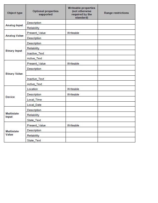
63 62
64 63
65 64

 on the client s")


66 7.8 ANNEX 2 - SECURITY SETTINGS IN THE WEB BROWSER AND JAVA CONTROL PANEL Problems showing updated measured values In some cases, connected clients can have problems to show updated measured values and pictures in their web browser. This is caused by cache-stored web pages (temporary Internet files) on the client s computer. To avoid this, the cache storing of the web browser should be shut off. Select the menu commands Tools Internet Options in Internet Explorer. On the general tab, click on the button Settings in Browsing history. Select Automatically. Open the Java Control Panel On the general tab, click on the button Settings. Uncheck Keep temporary files on my computer. 65


67 On the Security tab, add the IP-address to the Exception Site List. For example the standard service IP-address To add an IP-address, the complete address including must give in, not only the IP number The web pages split into different windows Make sure that the setting Navigate windows and frames across different domains is disabled in all web browsers that will surf to the EXO4 Web Server. Otherwise, the web pages may be split into different windows. Select the menu command Tools Internet Options in Internet Explorer. Select the tab Security and click on the button Custom level. Check that Navigate windows and frames across different domains is disabled. 66


68 7.8.3 Popup windows, JavaScript and Cookies Depending on security settings in the web browser, some functions may be inactivated. One important function that should not be activated is blocking of popup windows. Inactivate this function for the EXO4 Web Server website. Select the menu command Tools Internet Options in Internet Explorer. Select the tab Security and click on the button Custom level. Check that Use Pop-up Blocker is disabled. JavaScript and Cookies must also be activated in the clients web browsers. 67


69 7.8.4 Export function in the historical chart window For the export function in the historical chart window to function, you have to allow automatic file download, not only on the server, but also on client computers. This is done in the security settings for downloads in Windows Control Panel. Select the menu command Tools Internet Options in Internet Explorer. Select the tab Security and select the zone for which you want to allow downloads and click on the button Custom level. Check that Automatic prompting for file download is enabled. Systemair.B.V. Zanddonkweg 7a, 5144 NX Waalwijk, The Netherlands Phone: , Fax:
Pre-programmed room controller with communication
 revision 02 2016 RC-C3 Pre-programmed room controller with communication RC-C3 is a complete pre-programmed room controller from the Regio Midi series intended to control heating and cooling in a zone
Pre-programmed room controller with communication and hidden setpoint
 revision 02 2016 RC-C3H Pre-programmed room controller with communication and hidden setpoint RC-C3H is a complete pre-programmed room controller from the Regio Midi series intended to control heating
Digital Precise Air Control - DPAC
 Digital Precise Air Control - DPAC Mode Enable Sensor Options The temperature of this sensor will determine if the unit is in heating, cooling or vent mode during Occupied operation. The following options
Corrigo E. Second generation which contains all applications and languages
 revision 05 2009 Corrigo E Second generation which contains all applications and languages The controllers in the Corrigo E series are intended for applications within heating, boiler and ventilation control
Master devices. Type X-AIR-ZMAS. Zone master module for up to 25 zone modules, with integral webserver and interfaces to higher-level systems
 X X testregistrierung Type Web server, also for mobile devices Zone modules Zone master module for up to 25 zone modules, with integral webserver and interfaces to higher-level systems X-AIRCONTROL zone
Feature Summary. I. System
 I. System A. Supports up to 60 VAV HVAC Units 1. Each HVAC Unit Can Support up to 59 VAV Boxes 2. Constant Volume Units Can Be Integrated With VAV Units 3. System Can Support Over 3000 Controllers B. Fill-in
SAUTER flexotron800 V2 Ventilation V3.3. manual P P
 SAUTER flexotron800 V2 Ventilation V3.3 manual 2/175 Content Content 1 Generell notes 9 1.1 Disclaimer 9 1.2 Trademarks 9 1.3 Safety information 9 1.3.1 Mandatory note 9 1.3.2 General note 10 1.4 Notes
Corrigo E - manual Ventilation application
 Corrigo E - manual Ventilation application DISCLAIMER The information in this manual has been carefully checked and is believed to be correct. Regin however, makes no warranties as regards the contents
I/O ZONE 560/583 USERS GUIDE
 I/O ZONE 560/583 USERS GUIDE 641-224 641-242 641-237 1 Table of Contents Hot Gas Re-Heat Valve On/Off:... 15 THE ZONE CONTROLLER...4 Modulating Re-Heat Valve:... 16 SPECIFICATIONS...5 CONTROLLER COMPONENTS...6
TAP v2.10 Version Date: 6/12/13. Document Microprocessor Controller for Tempered Air Products
 Document 475595 Microprocessor Controller for Tempered Air Products Reference Guide for the Microprocessor Controller Please read and save these instructions. Read carefully before attempting to operate
Reference Guide for Microprocessor Controller
 Document 483586 Microprocessor Controller for Dedicated Outdoor Air System Reference Guide for Microprocessor Controller Please read and save these instructions for future reference. Read carefully before
Copyright AB Regin, Sweden, Corrigo E manual Ventilation application
 Copyright AB Regin, Sweden, 2013 Corrigo E manual Ventilation application DISCLAIMER The information in this manual has been carefully checked and is believed to be correct. Regin however, makes no warranties
Sauter flexotron 800 ventilation Manual
 Manual P100012082 Table of contents DISCLAIMER The information in this manual has been carefully checked and is believed to be correct. Fr. Sauter AG however, makes no warranties as regards the contents
Pre-programmed room controller with communication
 revision 01 2011 RC-C Pre-programmed room controller with communication RC-C is a complete pre-programmed room controller from the Regio Midi series intended to control heating and cooling in a zone control
VERSO DOMEKT. Residential ventilation units m³/h. Non residential ventilation units m³/h
 VENTILATION equipment VENTILATION equipment content DOMEKT Residential ventilation units 50 1 000 m³/h 15 VERSO Non residential ventilation units 1000 34 000 m³/h 61 Domekt R 17 Domekt R 200 V 19 Domekt
Corrigo E - User Manual Ventilation
 Corrigo E - User Manual Ventilation DISCLAIMER The information in this manual has been carefully checked and is believed to be correct. Regin however, makes no warranties as regards the contents of this
SECTION SEQUENCE OF OPERATIONS FOR HVAC CONTROLS
 SECTION 23 09 93 SEQUENCE OF OPERATIONS FOR HVAC CONTROLS PART 1 - GENERAL 1.1 SUMMARY A. This Section includes control sequences for HVAC systems, subsystems, and equipment. B. See Division 23 Section
SECTION SEQUENCE OF OPERATIONS FOR HVAC CONTROLS
 PART 1 - GENERAL SECTION 23 09 93 SEQUENCE OF OPERATIONS FOR HVAC CONTROLS 1.1 SUMMARY A. This Section includes control sequences for HVAC systems, subsystems, and other equipment. B. See Division 23 Section
SEQUENCE OF OPERATIONS
 SEQUENCE OF OPERATIONS DDC CONTROLLER: Controller with integral LCD readout for changing set points and monitoring unit operation. Provided with required sensors and programming. Factory programmed, mounted,
Room controllers with manual forced ventilation function
 revision 12 2016 RC-O Room controllers with manual forced ventilation function RC-O is a room controller from the Regio Mini series intended to control heating and cooling in a single zone. RC-O is a room
AirTrak. Digital Control System. User Manual. Touchscreen Systems
 AirTrak Digital Control System User Manual Touchscreen Systems Rev. 10-29-15 1 2 Table of Contents OVERVIEW... 8 NETWORKING... 9 AIRTRAK DEFAULT SETTINGS... 9 Unit Operating Modes... 10 MRT Controls...
Copyright AB Regin, Sweden, Corrigo manual Ventilation application
 Copyright AB Regin, Sweden, 2014 Corrigo manual Ventilation application DISCLAIMER The information in this manual has been carefully checked and is believed to be correct. Regin however, makes no warranties
ENERGY LIGHT USER S GUIDE ENERGY LIGHT USER S GUIDE
 ENERGY LIGHT USER S GUIDE Release January 2001 CONTENTS 1.0 GENERAL CHARACTERISTICS... 4 1.1 MAIN CHARACTERIS TICS... 4 2.0 USER INTERFACE (CODE C5121230)... 5 2.1 DISPLAY... 5 2.2 MEANING OF THE LEDS...
N M AirControl AHU. Control manual
 N 10.63 M 03-2016 AirControl AHU Control manual EN CONTENTS PAGE 1 - MONITORING AND CONTROL 2 1.1 The program 2 1.2 The HMI terminal 2 1.3 The controller 4 1.4 Description of the air handling units 4
Operation Manual Fighter ProVision Software. Version: 0.0 Revision: 1
 Operation Manual Fighter ProVision Software Version: 0.0 Revision: 1 TABLE OF CONTENTS 1. Introduction 5 2. Software Installation 5 3. PC Users 6 3.1 Introduction 6 3.2 Default Code 6 3.3 Edit PC User
WE TAKE BUILDING AUTOMATION PERSONALLY MANUAL CORRIGO
 WE TAKE BUILDING AUTOMATION PERSONALLY MANUAL CORRIGO Copyright AB Regin, Sweden, 2016 DISCLAIMER The information in this manual has been carefully checked and is believed to be correct. Regin however,
Manual for the integration in BMS/GTC
 Manual for the integration in BMS/GTC Communication parameters MODBUS RTU and BACNET COMMUNICATION UTBS PRO-REG Software Version 3.6 EN ÍNDEX 1. GENERALITIES...2 1.1. Introduction...2 1.2. signals types...2
Verasys System Operation Overview Technical Bulletin
 Contents subject to change. Verasys System Operation Overview Technical Bulletin Code No. LIT-12012370 Issued January 2016 Refer to the QuickLIT Web site for the most up-to-date version of this document.
1.0 Digital Controller
 Form CP-AHU D19_D21_D22 (11-17) D303072-A Obsoletes Forms CP-Preeva-D21 (1-16) Doc No 303072, CP-Preeva-D19 (1-16) Doc No 303071 Applies to: Preeva, MAPS, MAPS II, RPB, RPBL & SSCBL Series For Air Handler
SEQUENCE OF OPERATION FOR ALC CONTROL AIR SOURCE HEATPUMP RECIRCULATION AIR WITH ECONOMIZER
 SEQUENCE OF OPERATION FOR ALC CONTROL AIR SOURCE HEATPUMP RECIRCULATION AIR WITH ECONOMIZER Printed in the USA ADSOOASHPRAE 0117 Orig SEQUENCE OF OPERATION The ALC controller is turned on by a switch located
Natural Ventilation Controller with 24vDC drive NVC-1204
 Natural Ventilation Controller with 24vDC drive NVC-1204 BACnet Enabled C-036 08/11 FEATURES > 24V DC supply > Native BACnet communications > Master/Slave grouping (shared information) > 3 x 0-10V outputs
Room controller. RC is a room controller from the Regio Mini series intended to control heating and cooling in a single zone.
 revision 12 2016 RC Room controller RC is a room controller from the Regio Mini series intended to control heating and cooling in a single zone. RC is a room controller in the Regio series. The controller
Reference Guide for Microprocessor Controller
 Document 483232 Microprocessor Controller for Energy Recovery Reference Guide for Microprocessor Controller Please read and save these instructions for future reference. Read carefully before attempting
Natural Ventilation Controller with 24vDC drive NVC-1204
 Natural Ventilation Controller with 24vDC drive NVC-1204 BACnet Enabled C-038 08/16 FEATURES SPECIFICATION > 24V DC supply > Native BACnet communications > Master/Slave grouping (shared information) >
CLEVER CONTROL Version: V3
 CLEVER CONTROL Version: V3 INSTALLATION AND FUNCTIONING MANUAL USER AND BASIC VERSION Please, read these instructions carefully before attempting installation SECURITY ADVISE SIMBOLS Attention, Danger,
C-TRAC3 COMMUNICATION MANUAL FOR. BACnet NOVEMBER 2010 TO JANUARY 2014 USA HEAD OFFICE AND FACTORY
 A C-TRAC3 COMMUNICATION MANUAL FOR BACnet NOVEMBER 2010 TO JANUARY 2014 UNIT MODEL NO. UNIT SERIAL NO. SERVICED BY: TEL. NO: CANADIAN HEAD OFFICE AND FACTORY 1401 HASTINGS CRES. SE CALGARY, ALBERTA T2G
SAUTER flexotron 800 Ventilation application User Guide
 SAUTER flexotron 800 Ventilation application User Guide P100012091 1 Table of content P100012091 2 Table of content Table of content Table of content... 2 1 About this user guide... 4 2 About flexotron
HIGH EFFICIENCY FIRETUBE CONDENSING GAS BOILER
 This manual must be left with owner and should be hung on or adjacent to the boiler for reference. US HIGH EFFICIENCY FIRETUBE CONDENSING GAS BOILER MODELS CHS-85 through CHS-399 APPENDIX A CONTROLLER
SIMPLICITY BY DESIGN M52 CONTROLLER
 SIMPLICITY BY DESIGN M52 CONTROLLER CO-WORK TM CONNECTIVITY Our controller is at the heart of all of ClimateWorx product intelligence. Co-Work TM is based on a unique multi-master network system designed
I/A Series 716C 1/16 DIN Temperature Controller
 Product Specifications I/A Series 716C 1/16 DIN Temperature Controller PSS 2C-1B5 A The Foxboro 716C is a powerful compact, 1/16 DIN, microprocessor-based temperature controller that offers a variety of
Danfoss gas detection units
 Data sheet Danfoss gas detection units Types GD Premium, Premium+, Premium Duplex, Premium Remote, Premium Flex and Premium Uptime The Premium line gas detection units are used for monitoring and warning
Danfoss gas detection units
 Data sheet Danfoss gas detection units Types GD Premium, Premium+, Premium Duplex, Premium Remote, Premium Flex and Premium Uptime The Premium line gas detection units are used for monitoring and warning
SCC Inc. Master Panel. Specifications. Document No. TS 2010 February 11, Product Description. Sample Specification
 February 11, 2019 Master Panel Product Description The Master Panel shall provide lead/lag control and time based, automatic rotation of up to eight (8) boilers, when used in conjunction with LMV3 or LMV5
Danfoss gas detection unit Type GD Heavy Duty
 Data sheet Danfoss gas detection unit Type GD Heavy Duty The Heavy Duty gas detection units are used for monitoring and warning of hazardous Ammonia gas concentrations. They are intended for ATEX/ IECEx
EKC 347 Liquid Level Controller REFRIGERATION AND AIR CONDITIONING. Manual
 EKC 347 Liquid Level Controller REFRIGERATION AND AIR CONDITIONING Manual Contents Introduction...3 Valve compatibility...3 Features...3 Application examples...3 Ordering...3 Operating the EKC 347...4-5
50AZ/UZ. for rooftop units. 50 Hz. Installation, operation and maintenance instructions
 50AZ/UZ PRODIALOG for rooftop units Control 50 Hz Installation, operation and maintenance instructions 1 CONTENTS 1 SAFETY CONSIDERATIONS...3 1.1 General... 3 1.2 Avoid electrocution... 3 2 GENERAL DESCRIPTION...3
SPECIFICATION GUIDE FLEXAIR. Possibility to add auxiliary heaters: Gas, Electrical Heater, Hot Water Coil Possibility to add Heat Recovery Module
 SPECIFICATION GUIDE FLEXAIR Air-cooled packaged Rooftop unit Cooling only or Heat Pump Nominal cooling capacity: 85 to 234 kw Nominal heating capacity: 83 to 226 kw Possibility to add auxiliary heaters:
02/11/2015
 MIC48 With RS 485 link Part number 89422418 Heating and / or cooling function 2 independent alarms Load break detection 2 setpoint which can be selected remotely Manual / automatic power adjustment RS
MicroTech Unit Ventilator
 Open Protocol Data Information Packet Version 2.2 Group: Controls Date: April 1996 MicroTech Unit Ventilator Open Protocol Data Communications 2002 McQuay International - C O N F I D E N T I A L - This
READ AND SAVE THESE INSTRUCTIONS
 XXXXXXX-0 EN 1904 READ AND SAVE THESE INSTRUCTIONS BASIC-PLC CONTROLLER MANUAL For all Condair desiccant dryer with equipped with Basic- PLC valid from version: PLC-35/PLC-45 18.04.03 Dehumidification
MicroTech Self-Contained Air Conditioning System
 Open Protocol Data Information Packet Version 2.3 Group: Controls Date: October 1999 MicroTech Self-Contained Air Conditioning System Open Protocol Data Communications t 2002 McQuay International - C O
DX-9100 Applications from Engineering Services
 System 9100 Technical Manual 636.4 Application Examples Section Technical Bulletin Issue Date 0896 DX-9100 Applications from Engineering Services Introduction Page 3 Overview 3 Air Handling Unit Applications
SEQUENCE OF OPERATION FOR ALC CONTROL AIR SOURCE HEATPUMP 100% OUTSIDE AIR
 SEQUENCE OF OPERATION FOR ALC CONTROL AIR SOURCE HEATPUMP 100% OUTSIDE AIR Printed in the USA ADSOOASHPOA 0117 Orig SEQUENCE OF OPERATION The ALC controller is turned on by a switch located on its front
UNIFIED FACILITIES GUIDE SPECIFICATIONS
 USACE / NAVFAC / AFCEC / NASA UFGS-23 09 93 (November 2015) ----------------------------- Preparing Activity: USACE Superseding UFGS-23 09 23 (May 2011) UNIFIED FACILITIES GUIDE SPECIFICATIONS References
Temperature Controllers
 Model TEC-4100 1/4 DIN Model TEC-4100 1/4 DIN Temperature Controller Ordering Code: Power Input BOX 1 4 = 90-250 VAC 5 = 11-26 VAC / VDC TEC-4100- Configurable for 4 Programmable Outputs and NEMA 4X/IP65
Reference Guide for Microprocessor Controller
 Document 482641 Microprocessor Controller for Make-Up Air Products Reference Guide for Microprocessor Controller Please read and save these instructions for future reference. Read carefully before attempting
SECTION SEQUENCE OF OPERATION FOR HVAC CONTROLS PART 1 GENERAL
 SECTION 15910 SEQUENCE OF OPERATION FOR HVAC CONTROLS PART 1 GENERAL 1.1 RELATED DOCUMENTS A. Drawings and general provisions of the Contract, including General and Supplementary Conditions and other Division
FUNCTIONAL DESIGN SPECIFICATION
 Issue Date: Issued To: Revision: FUNCTIONAL DESIGN SPECIFICATION Specification Number: SP-XXXX Company Name Signature Date Issued By: Manutec Ltd. Approved By: Approved By: Approved By: Approved By: Authorised
ExactLogic BACnet Communicating Thermostat EXL01625 Sequence Datasheet Fan Coil with Modulatating H/C and PO-PC H/C
 ExactLogic BACnet Communicating Thermostat EXL01625 Sequence Datasheet Fan Coil with Modulatating H/C and PO-PC H/C DataSheet ev 1.10.403/4.02 November 6, 2012 Operating Sequence Standard Occupied During
Networkable Fan Coil Controller Specification and Installation Instructions
 Controller Models EFCB10T-OE1 (24Vac / 0 relays) EFCB12T-OE1 (240Vac / 0 relays) EFCB10TU4-OE1 (24Vac / 4 relays) EFCB12TU2-OE1 (240Vac / 2 relays) EFCB12TU4-OE1 (240Vac / 4 relays) TFL Series Thermostat
VMB1TSW Temperature sensor module for the Velbus system
 VMB1TSW Temperature sensor module for the Velbus system CONTENTS DESCRIPTION... 3 CHARACTERISTICS... 3 VELBUS CHARACTERISTICS... 5 OVERVIEW SENSOR MODULE... 7 EMBEDDING THE TEMPERATURE SENSOR... 8 EMBEDDING
Instructions for the fan motor control system with integrated wiring terminals SILVER C
 Instructions for the fan motor control system with integrated wiring terminals SILVER C 1. General The motor control system is used for controlling the type EC, 0.41-10 kw fan motors in the SILVER C units.
Touch Screen Thermostat. MTSC/SUPER, MTSC24/SUPER Series. MTS/SUPER, MTS24/SUPER Series. Owner s manual and technician settings
 Touch Screen Thermostat MTSC/SUPER, MTSC24/SUPER Series MTS/SUPER, MTS24/SUPER Series Owner s manual and technician settings -2 - Index 1. Owner s Manual... 4 1.1 Quick Guide. 4 1.2 Turning the unit ON
OVEN INDUSTRIES, INC.
 OVEN INDUSTRIES, INC. OPERATING MANUAL Model 5C7-252 TEMPERATURE CONTROLLER With PLC Inputs Introduction Thank you for purchasing our controller. The Model 5C7-252 is an exceptionally versatile unit and
1 DOCUMENT REVISION CONTROL ELEMENTS... 9
 CONTENTS Contents 1 DOCUMENT REVISION... 8 2 SOFTWARE VERSION... 8 3 BASIC DESCRIPTION... 8 4 CONTROL ELEMENTS... 9 4.1 BASIC DISPLAYS...10 4.2 CONTROL KEYS...11 4.2.1 Rotary button (Press / Turn)...11
ModSync Sequencing System Installation & Operation Manual. For use with Fulton Steam Boilers.
 ModSync Sequencing System Installation & Operation Manual For use with Fulton Steam Boilers. Revision 3.0 8/21/2008 - 2 - Table of Contents Introduction Page 4 Features Page 4 Sequence of Operation Page
Air handling unit. REC Temovex 400S-EC-RS. Experts on indoor climate in low-energy houses
 REC Temovex 4S-EC-RS Experts on indoor climate in low-energy houses RT 4S-EC-RS REC Temovex 4S-EC-RS ECO2 control system for low-energy and passive houses Comprises: - Air flow boost for warm and cold
Temperature + Humidity (%RH) Control & Recording System with 8 / 16 Channel Mapping. Touch Panel PPI
 Control & Recording System with 8 / 16 Channel Mapping. Touch Panel PPI") HumiTherm Ultra Temperature + Humidity (%RH) Control & Recording System with 8 / 16 Channel Mapping Mapping Unit Micro PLC Control Unit Touch Panel Touch Operation Panel PPI HumiTherm Ultra GSM Module
HumiTherm Ultra Temperature + Humidity (%RH) Control & Recording System with 8 / 16 Channel Mapping Mapping Unit Micro PLC Control Unit Touch Panel Touch Operation Panel PPI HumiTherm Ultra GSM Module
*IG1583EW* Aurora Touch UPC Kit Instruction Guide. Aurora Touch UPC Kit Instruction Guide
 Aurora Touch UPC Kit Instruction Guide For use in single compressor water-to-air equipment utilizing fi rmware UPCSWASTD01-01 Aurora Touch UPC Kit Instruction Guide *IG1583EW* IG1583EW 08/14 Aurora Touch
Instructions for the hand-held micro terminal of the fan motor control system, TBLZ-2-75 SILVER C
 Instructions for the hand-held micro terminal of the fan motor control system, TBLZ-2-75 SILVER C 1. General The hand-held micro terminal is used for setting the motor parameters of the SILVER C. 2. Installation
ECL Comfort 210 controller, Remote Control Units ECA 30 / 31 and Application keys Designed in Denmark
 ECL Comfort 210 controller, Remote Control Units ECA 30 / 31 and Application keys Designed in Denmark Description ECL Comfort 210 controller series The ECL Comfort 210 is an electronic weather compensated
ExactLogic BACnet Communicating Thermostat EXL01627 Sequence Datasheet Fan Coil with Modulating Fan and Heat or Cool Floating Heating and Cooling
 ExactLogic BACnet Communicating Thermostat EXL01627 Sequence Datasheet Fan Coil with Modulating Fan and Heat or Cool Floating Heating and Cooling DataSheet ev 1.12.304/4.0 June 14, 2016 Operating Sequence
Tri-Stack Smart System
 Tri-Stack Smart System TM Notes & Warnings - The protection provided by this equipment may be impaired if it is not used in the manner specified herein. - Ensure all wiring meets applicable national and
Dryer Controller M720
 User Manual Dryer Controller M720 Hardware version 2.00 Software version 2.00 Manual M720 Dryer controller Page 1 of 60 Document history Preliminary version: - Created in April, 2009 Hardware Version 2.00,
Multi-Gas-Controller MGC2
 Page 1 Aug. 2018 Gas measuring, monitoring and warning controller based on state-of-the-art micro-technology for continuous monitoring of the ambient air to detect toxic and combustible gases, refrigerants
Installation Guide. ECL Comfort 210, application A Table of Contents
 1.0 Table of Contents 1.0 Table of Contents... 1 1.1 Important safety and product information..................... 2 2.0 Installation... 4 2.1 Before you start.....................................................
USER'S MANUAL PU SENS 01 (A11) PU SENS 01 (A19) Sensor Control Panel
 PU SENS 01 (A19) Sensor Control Panel") USER'S MANUAL PU SENS 01 (A11) PU SENS 01 (A19) Sensor Control Panel PU SENS 01 CONTENTS Safety requirements... 3 Purpose... 4 Technical data... 4 Overall dimensions [mm]... 4 Mounting and set-up... 5
USER'S MANUAL PU SENS 01 (A11) PU SENS 01 (A19) Sensor Control Panel PU SENS 01 CONTENTS Safety requirements... 3 Purpose... 4 Technical data... 4 Overall dimensions [mm]... 4 Mounting and set-up... 5
TYPE CM-2201 NELSON SINGLE POINT CIRCUIT MANAGEMENT SYSTEM
 2 Line, 16 Characters/row LCD Display Temperature Input Range -50 C to +500 C -58 F to + 932 F Enclosure NEMA Type 4X Current Rating 30A max (resistive load only) Ambient Temperature -40 C to + 40 C -40
Operating Guide. ECL Comfort 210 / 296 / 310, application A247 / A Table of Contents
 1.0 Table of Contents 1.0 Table of Contents... 1 1.1 Important safety and product information..................... 2 2.0 Installation... 6 2.1 Before you start.....................................................
CONTROLS MANUAL For all Innovent and Valent air handling products
 CONTROLS MANUAL For all Innovent and Valent air handling products TABLE OF CONTENTS TABLE OF CONTENTS IMPORTANT INFORMATION Safety information...................................................................................
02/11/2015
 CTH 46 - CTD 43 / 46 CTD 46 Part number 89422108 CTH 46 Heating / cooling function Measurement and setpoint display CTD 43 Heating or cooling function Measurement display Measurement deviation display-setpoint
C-series Controllers for air handling systems
 C-series Controllers for air handling systems Corrigo, C-series, is a range of digital controllers for air-handling systems designed to be easy to use and operate, having a large capacity, and a high degree
Table of Contents. W2W Open
 W2W Open Points and Properties CARRIER CORPORATION 2013 A member of the United Technologies Corporation family Stock symbol UTX Catalog No. 11-808-457-01 3/27/2013 Table of Contents Introduction... 1
CDR-AL Room CO 2 Traffic Light Alarm Units and Sensors
 Product sheet SN1.402 Type CDR-AL CDR-AL Room CO 2 Traffic Light Alarm Units and Sensors CDR-AL sensors are designed to detect carbon dioxide concentration and temperature in the room spaces. The units
A. Base Bid: 1. Heating Contractor provide: a. Control sequences for HVAC systems, subsystems, and equipment.
 SECTION 23 09 93 - SEQUENCE OF OPERATIONS FOR HVAC CONTROLS PART 1 - GENERAL 1 WORK INCLUDES A. Base Bid: Heating Contractor provide: Control sequences for HVAC systems, subsystems, and equipment. B. Alternate
Safety & Installation Instructions
 Model 8800 Universal Communicating Thermostat Safety & Installation Instructions READ AND SAVE THESE INSTRUCTIONS Table of contents Installation Installation location recommendations... 2 Thermostat mounting...
Touch Screen Thermostat. MTSC/SUPER/CO2, MTSC24/SUPER/CO2 Series. MTS/SUPER/CO2, MTS24/SUPER/CO2 Series. Owner s manual and technician settings
 Touch Screen Thermostat MTSC/SUPER/CO2, MTSC24/SUPER/CO2 Series MTS/SUPER/CO2, MTS24/SUPER/CO2 Series Owner s manual and technician settings Rev. 2.4 Index 1. Owner s Manual... 3 1.1 Quick Guide. 4 1.2
Installation Manual. ATS Remote Annunciator Catalog 5350 DANGER WARNING D
 ASCO 5350 The ASCO 5350 ATS Remote Annunciator is listed under the Underwriter s Laboratories Standard UL-1008 for Automatic Transfer Switch accessories. This stand-alone device provides individual status
Installer Manual KNX Touchscreen Thermostat
 Installer Manual 02952 KNX Touchscreen Thermostat Index GENERAL FEATURES AND FUNCTIONALITY from page 5 ETS PARAMETERS AND COMMUNICATION OBJECTS from page 7 COMMUNICATION OBJECTS GENERAL FEATURES AND FUNCTIONALITY
MO n : 12JMC rév A
 CTT8 MO n : rév A Page 2 / 18 MODIFICATIONS Rev. Description Date Checked by Approuved by Z Creation 2012/02/12 JMC LA A First issue 2012/02/14 JMC LA INDEX Page 3 / 18 GENERALITY 4 INTRODUCTION 4 ACCESSORIES
CONTROLS MANUAL. CARRIERrtc basic & medium electronic control 48/50 EN/EH 50 HB/HF/NZ/NF. Original document
 CONTROLS MANUAL CARRIERrtc basic & medium electronic control 48/50 EN/EH 50 HB/HF/NZ/NF Original document Contents 1. General description....5 2. Set-up... 6 2.1. micropc control board... 6 2.2. TCO user
TEMPERATURE CONTROL MODULE MODEL R3-TC2
 INSTRUCTION MANUAL R3-TC2 TEMPERATURE CONTROL MODULE MODEL R3-TC2 CONTENTS BEFORE USE... 2 POINTS OF CAUTION... 2 COMPONENT IDENTIFICATION... 2 INSTALLATION... 2 EXTERNAL DIMENSIONS unit: mm (inch)...
Tstat9. Bacnet Thermostat
 Tstat9 Bacnet Thermostat This full-featured thermostat is designed for cooling and heating systems in residential and commercial buildings.the thermostat can be configured for or use with air handlers,fan
York 25-Ton VAV Rooftop Unit
 HVAC PRO for Windows User s Manual 637.5 OEM Section Technical Bulletin Issue Date 0996 York 25-Ton VAV Rooftop Unit Introduction Page 3 Overview *3 Configuration 5 Sequence of Operation 7 Modes of Operation
BLAUAIR AUTOMATIC CONTROL SYSTEM
 BLAUAIR AUTOMATIC CONTROL SYSTEM S30 (KVENT, TH-TUNE) S31 (KVENT) S32 (KVENT, PGDE) EN USER S MANUAL CONTENTS Safety requirements... 3 Purpose... 4 Technical data... 5 Installation and set-up... 6 Control...
EC3-X33 Stand-alone Superheat Controller Technical Data
 Technical Data EC3-X33 is a stand-alone universal superheat controller for air conditioning, refrigeration and industrial applications such as chillers, industrial process cooling, rooftops, heat pumps,
CM3500 Controller - ClimateMaster DOAS Water-Source Heat Pumps - Rev.: 7 Oct, 2008B
 2 CM3500 Controller - ClimateMaster DOAS Water-Source Heat Pumps - Rev.: 7 Oct, 2008B CAUTION CAUTION - ONLY TRAINED, QUALIFIED PERSONNEL SHOULD INSTALL AND/OR SERVICE CLIMATEMASTER EQUIPMENT. SERIOUS
OPERATING INSTRUCTIONS
 COMFORT CONTROL CENTER 2 THERMOSTAT OPERATING INSTRUCTIONS PROGRAMMABLE THERMOSTAT MODEL 3314080.000 BLACK 3314080.015 WHITE USA SERVICE OFFICE Dometic Corporation 1120 North Main Street Elkhart, IN 46514
Replaceable LED modules. Sleep or unattended mode. Auto-silence and auto-acknowledge
 Replaceable LED modules 11 Alarm Sequences as per ISA-18.1 standard Each channel/window fully field programmable RS232 or RS485 MODBUS-RTU communication Repeat relay for each window and multifunction relays
VAV Thermostat Controller Specification and Installation Instructions. Model TRO24T4XYZ1
 Model TRO24T4XYZ1 Description The TRO24T4XYZ1 is a combination controller and thermostat. The VAV Thermostat Controller is designed for simple and accurate control of any variable air volume box in a number