Corrigo E - User Manual Ventilation
|
|
|
- Winfred Haynes
- 5 years ago
- Views:
Transcription


1 Corrigo E - User Manual Ventilation
2 DISCLAIMER The information in this manual has been carefully checked and is believed to be correct. Regin however, makes no warranties as regards the contents of this manual and users are requested to report errors, discrepancies or ambiguities to Regin, so that corrections may be made in future editions. The information in this document is subject to change without prior notification. The software described in this document is supplied under licence by Regin and may be used or copied only in accordance with the terms of the licence. No part of this document may be reproduced or transmitted in any form, in any fashion, electronically or mechanically, without the express, written permission of Regin. COPYRIGHT AB Regin. All rights reserved. TRADEMARKS Corrigo E, E-tool, EXOdesigner, EXOreal, EXO4, EXOline, EXO4 Web Server, Optigo, Regio and Regio Tool are registered trademarks of AB Regin. Windows, Windows 2000, Windows XP, and Windows Server 2003 are registered trademarks of Microsoft Corporation. Some product names mentioned in this document are used for identification purposes only and may be the registered trademarks of their respective companies. Revision G, December 2007 Document Revision:
3 Table of contents Chapter 1 About the manual 4 Chapter 2 About Corrigo E 5 Chapter 3 Installation and wiring 8 Chapter 4 Commissioning 15 Chapter 5 Functional description 17 Chapter 6 Starting and stopping the unit 34 Chapter 7 Display, LEDs and buttons 36 Chapter 8 Access rights 38 Chapter 9 Configuration 40 Chapter 10 Settings 58 Chapter 11 Scheduler 62 Chapter 12 Setpoint 64 Chapter 13 Manual / Auto 68 Chapter 14 In- / Outputs 70 Chapter 15 Other functions 71 Chapter 16 Index 72
4 Chapter 1 About the manual This manual covers all the models in the Corrigo E series of ventilation controllers. This revision covers program revision More information More information about Corrigo E can be found in: Manual E-tool Manual of how to configure the controllers Lon-interface variable list Variable list for the Corrigo E series Network variables for EXOline and Modbus Variable list for EXOline and Modbus communication CE - Declaration of conformity, Corrigo E The information is available for download from Regin s homepage, Corrigo E Ventilation manual, revision G Chapter 1 About the manual 4
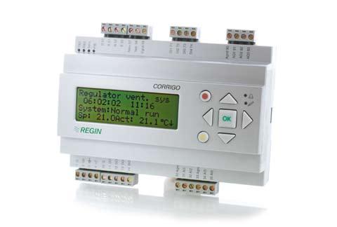
5 Chapter 2 About Corrigo E Corrigo E for ventilation is a complete new range of programmable controllers for control of building facility systems as air handling units. Corrigo E series for ventilation comprises three model sizes: 8, 15 or 28 in-/outputs. Available with or without front panel display and buttons. For units without front panel display and buttons a separate, cable-connected terminal E-DSP with display and buttons is available. All programming and normal handling can be done using the display and buttons or from a connected computer running Corrigo E-tool and using EXOline for communication. The temperature controller is based on a supply air PI-controller for heating control with a preprogrammed set of control modes. To this controller can be bound a number of different control functions and analogue and digital input and output functions. The choice of which functions are to be used is free, the only restriction lying in the physical number of inputs and outputs that the different models have. The Corrigo is designed for DIN-rail mounting. The program for an air handling unit contains, apart from other things, the following functions: Different temperature control modes Supply air temperature control, with or without outdoor temperature compensation Room temperature control (cascade controller) Exhaust air temperature control (cascade controller). With control of: Heat exchanger (Liquid connected-, plate- or rotating) or mixing dampers. Heater battery; Water with frost protection or electric. Chiller Supply air and exhaust air fans (single-speed, two-speed, pressure controlled or flow controlled). Fire dampers. Circulation pumps heating, cooling, exchanger. Humidity control Either Humidification or Dehumidification or both Humidification and Dehumidification. Timer control For starting and stopping the unit. Demand controlled ventilation In buildings with strongly varying occupancy the fan speeds or mixing dampers can be controlled by the air quality measured by a CO 2 /VOC sensor. Support control When using the control function Room control or exhaust air temperature control with a room sensor connected it is possible to utilise support-heating and/or support-cooling. Minimum running time is settable minutes (factory setting 20 minutes). Corrigo E Ventilation manual, revision G Chapter 2 About Corrigo E 5
6 Free cooling The function is used during the summer to cool the building during the night using cool outdoor air thereby reducing the need to run chillers during the day. Step controllers Heating/Cooling As an alternative to the analogue control of Actuator heating Y1 or Actuator cooling Y3 step controllers can be used for controlling heating or cooling in steps using digital control. Corrigo E hardware overview Model 8 8D 15 15D 28 28D Analogue Inputs Digital Inputs Universal Inputs Analogue Outputs Digital Outputs RS485 Yes Yes Yes Yes Yes Yes LON Option Option Option Option Option Option TCP/IP Option Option Option Option Option Option Display No Yes No Yes Nej Yes Ext. display Option No Option No Option No Technical data Protection class... IP20 Display...4 rows of 20 characters. Background illumination. LEDs Yellow...Settable parameter Red...Alarm Clock...Year base 24 hour clock with battery backup. Automatic summer-/winter-time changeover. Operating system...exoreal Supply voltage...24 V AC, 6 VA Dimensions x123x60 (WxHxD incl. terminals) Casing... Standard Euronorm Mounting... On DIN-rail Operation Climatic conditions according to IEC Class 3k5 Ambient temperature C Ambient humidity...max 95% RH Mechanical requirements according to IEC Class 3M3 Vibration...IEC , Test FC, vibration Sinusoidal Shock...IEC , Test Ea Transport Climatic conditions according to IEC Class 2k3 Ambient temperature C Air humidity...max 95% RH Mechanical requirements according to IEC Class 2M2 Vibration...IEC , Test FC, vibration Sinusoidal Shock...IEC , Test Ea Free fall... IEC , Test Ed Storage Climatic conditions according to IEC Class 1k3 Ambient temperature C Air humidity...max 95% RH Corrigo E Ventilation manual, revision G Chapter 2 About Corrigo E 6
7 Battery Type...Replaceable Lithium cell Battery life...better than 5 years Warning... Low battery warning Battery backup...memory and real time clock Communication EXOline Port 1, insulated via a built-in RS485 contact. The basic version of Corrigo E can communicate with Modbus. You do not need an activation code. Corrigo E can be ordered with a communication port for TCP/IP or LON. CE-marking Conforms with the EMC standards: CENELEC EN :2001, CENELEC EN :2001. Inputs Analogue inputs AI...Settable 0 10 V DC or PT1000, 12 bit A/D Digital inputs DI...Potential free closure Universal inputs UI...Can be set to act as either an analogue input or a digital input with specifications as above Outputs Analogue outputs AO... Settable 0 10 V DC; 2 10 V DC; 10 0 V DC or 10 2 V DC 8 bit D/A short-circuit protected Digital outputs DO... Triac outputs, 24 V AC, 0.5 A continuous Options LON... FT3150, gives a second communication route TCP/IP...Replaces RS485 for EXOline (Port 1) communication External hand terminal, E-DSP...For use with Corrigo E units without display Position of the terminals on Corrigo E Corrigo E Ventilation manual, revision G Chapter 2 About Corrigo E 7
8 Chapter 3 Installation and wiring 3.1 Installation Corrigo E can be mounted in a DIN-standard casing (minimum 9 modules), on a DIN-rail in a cabinet or, using a suitable front-mounting kit, in a cabinet door or other control panel. Ambient temperature: 0 50 C. Ambient humidity: max. 95 %RH, non-condensing. 3.2 Wiring At the end of this chapter there are wiring diagrams showing the factory set configuration. We have also included blank diagrams. Since the function of most of the inputs and outputs depends on the programming of the unit the final wiring diagram cannot be filled in until the installer has decided how to use the inputs/outputs. It is important to make sure that the wiring is correctly done and in accordance with the instructions given in this manual Supply voltage 24 V AC ±15%, 50/60 Hz. 6 VA If the Corrigo E and the actuators connected to it share the same transformer it is essential that the same transformer-pole is used as reference for all the equipment. Failure to do so will prevent the equipment from functioning as intended and may also lead to damages Inputs and outputs The list of input and output functions in section is a handy instrument to help you keep track of which inputs and outputs you will need to configure. Analogue inputs Analogue inputs must refer to an A-gnd terminal placed in the same terminal block as the input being wired. Analogue inputs can, depending on the configuration, be used for either PT1000 temperature sensors or for 0 10 V DC analogue input signals, for example from a pressure transmitter. Digital inputs Digital inputs must refer to C+ on terminal 4. Digital inputs may only be wired to voltage-free contacts. Any external voltage applied to a digital input may harm the unit. Universal inputs A universal input can be configured to act as either an analogue input or as a digital input. A universal inputs configured as an analogue input can, depending on the configuration, be used for either PT1000 temperature sensors or for 0 10 V DC analogue input signals, for example from a pressure transmitter. Universal inputs configured as an analogue input must refer to an A-gnd terminal placed in the same terminal block as the input being wired. A universal input configured as a digital input must, just like other digital inputs refer to C+ on terminal 4. It may only be wired to voltage-free contacts. Corrigo E Ventilation manual, revision G Chapter 3 Installation and wiring 8
9 Analogue outputs Analogue outputs must refer to the A-gnd terminal placed in the AO terminal block. All analogue outputs can be individually set to any one of the following signals: 0 10 V DC 2 10 V DC 10 0 V DC 10 2 V DC If the Corrigo E and the actuators connected to it share the same transformer it is essential that the same transformer-pole is used as reference for all the equipment. Failure to do so will prevent the equipment from functioning as intended and may also lead to damages. Digital outputs Digital outputs must refer to G DO on terminal 10. All the digital outputs are triac controlled. The outputs will deliver 24 V AC, 0.5 A continuous. The outputs cannot be used to drive DC relays Input and output lists Use these lists during commissioning to help you keep track of which input and output functions you wish to use. Analogue inputs Analogue input signal Outdoor temperature sensor Supply air temperature sensor Exhaust air temperature sensor Extract air temperature sensor Room temperature sensor 1 Room temperature sensor 2 CO 2 /VOC sensor V DC Extra sensor / Setpoint potentiometer Pressure transmitter, supply air 0 10 V DC Pressure transmitter, exhaust air 0 10 V DC De-icing sensor, heat exchanger Frost protection sensor Corrigo E Ventilation manual, revision G Chapter 3 Installation and wiring 9
10 Digital inputs Digital input signal Filter guard, supply air and exhaust air Run-indication/alarm circulation pump, heating Run-indication/alarm circulation pump, cooling Run-indication/alarm circulation pump, exchanger Fire alarm Fire damper end-switch monitoring Extended running 1/1-speed Extended running 1/2-speed External stop External alarm Flow-switch Rotation sentinel, exchanger Run-indication/alarm supply air fan Run-indication/alarm exhaust air fan De-icing, exchanger High temp limit switch/frost prot. thermostat The universal inputs on Corrigo E28 can, individually, be configured as either analogue inputs using any of the analogue input signals above or as digital inputs using any of the digital inputs above. Analogue outputs Analogue output signal Y1 Actuator Heating Y2 Actuator Exchanger Y3 Actuator Cooling Y4 Frequency converter, supply air fan Y5 Frequency converter, exhaust air fan Y6 Actuator Humidity control Split of any one of temp outputs Y1, Y2 or Y3 Corrigo E Ventilation manual, revision G Chapter 3 Installation and wiring 10
11 Digital outputs Digital output signal Start/stop supply air fan (SAF) 1/1-speed Start/stop exhaust air fan (EAF) 1/1-speed Start/stop supply air fan (SAF) 1/2-speed Start/stop exhaust air fan (EAF) 1/2-speed Start/stop circulation pump, heating Fire dampers Sum alarm A- and B-alarm Sum alarm A-alarm Sum alarm B-alarm Start/stop circulation pump, cooling Start/stop circulation pump, liquid exchanger Activation-signal SAF frequency converter Activation-signal EAF frequency converter Activation heating Activation cooling Activation heat exchanger Extract air close-off damper Fresh air close-off damper Recirculation damper Heating 3-pos. actuator, increase Heating 3-pos. actuator, decrease Exchanger 3-pos. actuator, increase Exchanger 3-pos. actuator, decrease Cooling 3-pos. actuator, increase Cooling 3-pos. actuator, decrease Step controller heating, step 1 Step controller heating, step 2 Step controller heating, step 3 Step controller heating, step 4 Step controller cooling, step 1 Step controller cooling, step 2 Step controller cooling, step 3 Extra Timer channel 1 Extra Timer channel 2 Extra Timer channel 3 Extra Timer channel 4 Extra Timer channel 5 Humidity Corrigo E Ventilation manual, revision G Chapter 3 Installation and wiring 11
12 Wiring diagram Corrigo E28V factory configuration (See also picture of the position of the terminals on page 7) 1 G 50 B Supply voltage 24 V AC, ±15%. 50/60 Hz 2 G0 51 A 3 Protective earth 52 N 4 +C +24 V DC. Reference for digital inputs DI. 53 E RS485 EXOline / Modbus 10 G DO Reference for digital outputs DO. 57 Net+ 11 DO1 Start/stop supply air fan (SAF) 1/1-speed 58 Net- LON-connection (LON-versions only) 12 DO2 Start/stop exhaust air fan (EAF) 1/1 speed 59 Egnd 13 DO3 Start/stop supply air fan (SAF) 1/2-speed 14 DO4 Start/stop exhaust air fan (EAF) 1/2 speed 71 DI1 Filter guard, supply air and exhaust air 15 DO5 Start/stop Circulation pump, Heating 72 DI2 Run indication /alarm, Circ. pump Heating 16 DO6 Fire dampers 73 DI3 Run indication /alarm, Circ. pump Cooling 17 DO7 Sum alarm A + B 74 DI4 Fire alarm 75 DI5 Fire damper end-switch monitoring 30 Agnd Reference pole for analogue inputs AI 76 DI6 Extended running 1/1-speed 31 AI1 Outdoor temperature sensor 77 DI7 External alarm 32 AI2 Supply air temperature sensor 78 DI8 External stop 33 Agnd Reference pole for analogue inputs AI 34 AI3 Exhaust air temperature sensor 90 Agnd Reference pole for analogue outputs AO 35 AI4 Room temperature sensor 1 91 AO1 Y1 Actuator Heating 92 AO2 Y2 Actuator Exchanger 40 Agnd Reference pole for universal inputs UI 93 AO3 Y3 Actuator Cooling 41 UI1 DI Run indication / Motor protection SAF 94 AO4 Y4 SAF frequency converter 42 UI2 DI Run indication / Motor protection EAF 95 AO5 Y5 EAF frequency converter 43 Agnd Reference pole for universal inputs UI 44 UI3 Exchanger de-icing sensor 45 UI4 Frost protection sensor Wiring diagram Corrigo E15V factory configuration 1 G 50 B Supply voltage 24 V AC, ±15%. 50/60 Hz 2 G0 51 A 3 Protective earth 52 N 4 +C +24 V DC. Reference for digital inputs DI. 53 E RS485 EXOline / Modbus 10 G DO Reference for digital outputs DO. 57 Net+ 11 DO1 Start/stop supply air fan 1/1-speed 58 Net- LON-connection (LON-versions only) 12 DO2 Start/stop exhaust air fan (EAF) 1/1 speed 59 Egnd 13 DO3 Start/stop Circulation pump, Heating 14 DO4 Sum alarm A + B 71 DI1 Run indication / Motor protection SAF 72 DI2 Run indication / Motor protection EAF 30 Agnd Reference pole for analogue inputs AI 73 DI3 Run indication /alarm, Circ. pump Heating 31 AI1 Outdoor temperature sensor 74 DI4 Extended running 32 AI2 Supply air temperature sensor 33 Agnd Reference pole for analogue inputs AI 90 Agnd Reference pole for analogue outputs AO 34 AI3 Frost protection sensor 91 AO1 Y1 Actuator Heating 35 AI4 Room temperature sensor 1 92 AO2 Y2 Actuator Exchanger 93 AO3 Y3 Actuator Cooling Corrigo E Ventilation manual, revision G Chapter 1 12
13 Wiring diagram Corrigo E8V factory configuration 1 G 50 B Supply voltage 24 V AC, ±15%. 50/60 Hz 2 G0 51 A 3 Protective earth 52 N 4 +C +24 V DC. Reference for digital inputs DI. 53 E RS485 EXOline / Modbus 10 G DO Reference for digital outputs DO. 57 Net+ 11 DO1 Start/stop supply air fan (SAF) 1/1-speed 58 Net- 12 DO2 Start/stop Circulation pump, Heating 59 Egnd LON-connection (LON-versions only) 30 Agnd Reference pole for analogue inputs AI 71 DI1 Run indication / Motor protection SAF 31 AI1 Outdoor temperature sensor 72 DI2 Run indication /alarm, Circ. pump Heating 32 AI2 Supply air temperature sensor 73 DI3 High temp. limit switch / Frost prot. thermostat 90 Agnd Reference pole for analogue outputs AO 91 AO1 Y1 Actuator Heating Empty wiring diagram Corrigo E28V 1 G 50 B Supply voltage 24 V AC, ±15%. 50/60 Hz 2 G0 51 A 3 Protective earth 52 N 4 +C +24 V DC. Reference for digital inputs DI. 53 E RS485 EXOline / Modbus 10 G DO Reference for digital outputs DO. 57 Net+ 11 DO1 58 Net- LON-connection (LON-versions only) 12 DO2 59 Egnd 13 DO3 14 DO4 71 DI1 15 DO5 72 DI2 16 DO6 73 DI3 17 DO7 74 DI4 75 DI5 30 Agnd Reference pole for analogue inputs AI 76 DI6 31 AI1 77 DI7 32 AI2 78 DI8 33 Agnd Reference pole for analogue inputs AI 34 AI3 90 Agnd Reference pole for analogue outputs AO 35 AI4 91 AO1 92 AO2 40 Agnd Reference pole for universal inputs UI 93 AO3 41 UI1 94 AO4 42 UI2 95 AO5 43 Agnd Reference pole for universal inputs UI 44 UI3 45 UI4 Corrigo E Ventilation manual, revision G Chapter 1 13
14 Empty wiring diagram Corrigo E15V 1 G 50 B Supply voltage 24 V AC, ±15%. 50/60 Hz 2 G0 51 A 3 Protective earth 52 N 4 +C +24 V DC. Reference for digital inputs DI. 53 E RS485 EXOline / Modbus 10 G DO Reference for digital outputs DO. 57 Net+ 11 DO1 58 Net- LON-connection (LON-versions only) 12 DO2 59 Egnd 13 DO3 14 DO4 71 DI1 72 DI2 30 Agnd Reference pole for analogue inputs AI 73 DI3 31 AI1 74 DI4 32 AI2 33 Agnd Reference pole for analogue inputs AI 90 Agnd Reference pole for analogue outputs AO 34 AI3 91 AO1 35 AI4 92 AO2 93 AO3 Empty wiring diagram Corrigo E8V 1 G 50 B Supply voltage 24 V AC, ±15%. 50/60 Hz 2 G0 51 A 3 Protective earth 52 N 4 +C +24 V DC. Reference for digital inputs DI. 53 E RS485 EXOline / Modbus 10 G DO Reference for digital outputs DO. 57 Net+ 11 DO1 58 Net- 12 DO2 59 Egnd LON-connection (LON-versions only) 30 Agnd Reference pole for analogue inputs AI 71 DI1 31 AI1 72 DI2 32 AI2 73 DI3 90 Agnd Reference pole for analogue outputs AO 91 AO1 Corrigo E Ventilation manual, revision G Chapter 1 14
15 Chapter 4 Commissioning General Before the Corrigo can be used it must be configured, inputs and outputs must be assigned and all relevant parameters must be set. All commissioning can be done using the Corrigo front panel display and buttons or using the display unit E-DSP. Corrigo E-tool The best way however, is to configure the Corrigo E by using Corrigo E-tool. Corrigo E-tool is a PC-based configuration program specially developed to simplify the commissioning of the Corrigo E-series. When using E-tool the whole configuration and all settings can be done on the computer and then be downloaded to the Corrigo. An infinite number of different configurations can be saved in computer memory for later use How to do it For configuration using E-tool, see the E-tool manual. For configuration using the front panel there are two ways to go depending on how much help you need. Option 1: Jump straight to chapter 7 and 8 Display, LEDs and buttons and Access rights. After mastering the button and menu system, connect power to your Corrigo, log on at System level and go to the menu Configuration. For the time being, skip the configuration menu Inputs/Outputs and start by configuring Control functions. Run through the configuration menus in order and set whatever functions and parameters you wish to include. Use chapter 6 of this manual for reference. Keep track of which inputs and outputs you will need. To help you, there is a list of input and output functions provided in chapter 3, (3.2.3 Input / Output list.) Finally, configure Inputs/Outputs. Exit Configuration and go to Settings Set the control values in Settings Set the clock and scheduler functions in Time Settings. Set the control setpoints in Actual/Setpoint. Your Corrigo should now be ready to run. Option 2: Read this manual in the order given below: The manual has been designed to act as a guide through the commissioning. The last chapters of the manual, not listed below, cover menus and functions that are not used during commissioning. Corrigo E Ventilation manual, revision G Chapter 4 Commissioning 15
16 Functional description Start by reading chapter 5. Functional description below. Some functions are essential to the working of the unit and must be included. Others are more of the nature of optional extras which can be excluded. At the end of each function description there is a table of the necessary inputs and outputs to implement the function. At the end of the manual there is a list of all the analogue and digital inputs and outputs. As you read, mark in the list the inputs and outputs you will be using for the application you are building. Note that the universal inputs in Corrigo E28 can, individually, be configured as either analogue or digital inputs. Display, buttons and LEDs Read chapter 7 on how to use the front panel buttons to navigate the Corrigo E menu system. Access rights Chapter 8. Learn how to log on to the Corrigo E Configuration Chapter 9. Configuration. Connect power to the Corrigo. Using the buttons and menu system, go through the configuration menus covering the functions you wish to use. On delivery the units already have the inputs and outputs assigned to various functions. These can, of course, be changed. In chapter 3 Installation and wiring there are two sets of wiring diagrams, one set showing the pre-configured input / output configuration and one set where you can fill your own configuration choices. Settings Set the control parameters, P-band, I-time for the temperature control. Set the control parameters for the pressure control if you have pressure- or flow- controlled fans. Set the control parameters for the humidity control if activated. Set the alarm parameters; alarm levels and delay times. Time Settings Set the clock and calendar functions. Setpoints Set all the setpoints for all active control loops. Hand/Auto Learn to use manual control. Very useful for testing out your system. Corrigo E Ventilation manual, revision G Chapter 4 Commissioning 16
17 Chapter 5 Functional description 5.1 Temperature control General Corrigo E has a choice of the following control modes: 1. Supply air control 2. Outdoor temperature compensated supply air control 3. Cascaded room temperature control 4. Outdoor temperature dependent switching between room control and supply air control 5. Outdoor temperature dependent switching between exhaust air control and supply air control 6. Exhaust air control The supply air temperature controller is reverse acting, i. e. the output will increase for decreasing temperature. The controller is a PI-controller with settable P-band and I-time. In the first two modes the supply air temperature will be controlled using the supply air temperature and the user setpoint values as control inputs. In modes 3 and 6 the supply air is controlled as part of a cascade controller together with the room/exhaust temperature controller. The room/exhaust temperature offset will dictate the supply air temperature setpoint. Mode 4 and 5 vary according to the outdoor temperature: Supply air control in winter and cascaded room control or cascaded exhaust air control in summer. In applications with mixing dampers instead of heat exchanger the signal for the damper control will be reversed compared to the signal for heat exchanger control i. e. decreasing signal on increasing heat demand. This is done automatically on configuring the exchanger output = dampers. The heater can be either a hot water heater battery or an electric heater. Outputs The supply air controller output is split between one or more of the output blocks Y1, Y2 and Y3 for heating, heat exchanger and cooling. The output blocks can be bound to either analogue 0 10 V DC outputs or to 3-position increase/decrease outputs. Each output block has two parameters for setting the control range: Controller signal at which the output should be 0% Controller signal at which the output should be 100% These settings are used to establish the output activation order and to split the P-band between the outputs. For example: 0% Cooling at HCout = 30% 100% Cooling at HCout = 0% 0% Heat exch. at HCout =34% 100% Heat exch. at HCout = 65% Corrigo E Ventilation manual, revision G Chapter 5 Functional description 17
18 0% Heating at HCout = 65% 100% Heating at HCout = 100% Output signal 100% 0% Controller signal 100% Cooling Heat exch. Heating 65% 34% 30% 0% Heat demand It is also possible to split one of the three analogue outputs into two equal parts to give a fourth output sequence for temperature control Control modes 1. Supply air control The supply air temperature is kept at the setpoint value by controlling the output signals for Heating, Heat exchanger and Cooling. A single PI control loop is used. The setpoint value is set using the front panel or alternatively using an external setpoint device. Alarms for high and low supply air temperature are active. Alarm for control offset of the supply air temperature is active. 2. Outdoor temperature compensated supply air control The supply air temperature setpoint is outdoor temperature compensated using a control curve with 6 node points. The supply air temperature is kept at the setpoint value by controlling the output signals for Heating, Heat exchanger and Cooling. A single PI control loop is used. Alarms for high and low supply air temperature are active. Alarm for control offset of the supply air temperature is active. 3. Room control with cascade function Cascade control of room temperature and supply air temperature to achieve a constant, settable room temperature. The room controller output signal generates the supply air controller s setpoint value. One or two room sensors can be connected. If two sensors are connected the average of their values will be used. The number of room sensors is detected automatically. The room temperature is kept at the setpoint value by controlling the output signals for Heating, Heat exchanger and Cooling. Two PI loops are used. Corrigo E Ventilation manual, revision G Chapter 5 Functional description 18
19 4. Outdoor temperature dependent switching between supply air temperature control and room temperature control When the outdoor temperature is lower than a settable limit (winter), outdoor compensated supply air temperature control will be active, otherwise (summer) cascaded room temperature control. 5. Outdoor temperature dependent switching between supply air temperature control and exhaust air temperature control When the outdoor temperature is lower than a settable limit, outdoor compensated supply air temperature control will be active, otherwise cascaded exhaust air temperature control. 6. Exhaust air control with cascade function Cascade control of exhaust air temperature and supply air temperature to achieve a constant, settable room temperature. The exhaust air controller output signal generates the supply air controller s setpoint value. The exhaust air temperature is kept at the setpoint value by controlling the output signals for Heating, Heat exchanger and Cooling. Two PI loops are used. Inputs and outputs Control modes AI AI AI AI AI AI Supply air sensor AI AI AI Outdoor temperature sensor AI AI AI AI AI AI AI AI Room temperature sensor(s) AI AI Exhaust air sensor Frost protection sensor (water heating, optional) Frost protection thermostat DI DI DI DI DI DI (water heating, optional) AO AO AO AO AO AO Y1 Heating 0 10 V DC AO AO AO AO AO AO Y2 Exchanger 0 10 V DC AO AO AO AO AO AO Y3 Cooling 0 10 V DC Extra split Y1, Y2 or Y3 AO AO AO AO AO AO 0 10 V DC (optional) DO DO DO DO DO DO Heating 3-pos. increase DO DO DO DO DO DO Heating 3-pos. decrease DO DO DO DO DO DO Exch. 3-pos. increase DO DO DO DO DO DO Exch. 3-pos. decrease DO DO DO DO DO DO Cooling 3-pos. increase DO DO DO DO DO DO Cooling 3-pos. decrease Heater types Water heating Control When the unit is in running mode the heating valve is controlled by the analogue output Y1 Heating or by two digital outputs Heating 3-pos. actuator, increase and Heating, 3-pos. actuator, decrease. Corrigo E Ventilation manual, revision G Chapter 5 Functional description 19
20 Frost protection The heater return water temperature is measured using the analogue input Frost protection sensor. Low temperatures will generate an internal, proportional signal that is used to force the heating valve open thereby preventing freeze-up of the heater. The internal signal ( Internal signal ) is 100 % when the signal Frost protection sensor is equal to or lower than Alarm level. When Frost protection sensor is higher than Alarm level the signal declines linearly to 0 for Frost protection sensor equal to or higher than Alarm level + Prop. Band. When Internal signal reaches 100% or the digital input High temp limit/frost protection is activated, the unit is shut down, the heating output is set to completely open mode and an alarm is activated. The unit will restart after the alarm has been acknowledged and the value at Frost protection sensor has returned to normal. 100 % Internal signal Prop.band 0 % Alarm level Frost protection sensor Shutdown mode If frost protection is activated the controller will go into Shutdown mode when the running mode switches to Off. The shutdown controller will control the heating output to maintain a constant settable temperature at the frost protection sensor. The frost protection alarm level is set in the menu Actual/Setpoint Electric heating Control The heating is controlled using the analogue output Y1 Heating. On activation of the digital input High temp limit/frost protection the unit will be shut down, either according to the stop sequence described in section Start/stop of unit or as an emergency shut down. The unit will restart after the alarm has been acknowledged and High temp limit/frost protection has reset. Note that activation of the input signal Flow switch will also stop the unit. Control voltage Relay el. heating Contr. voltage High limit thermostat Auxiliary relay Corrigo Wiring suggestion high temp limit when using electric heating. Contacts drawn inactivated. Corrigo E Ventilation manual, revision G Chapter 5 Functional description 20
21 N.B. It is important that the high temperature thermostat is hardwired to disconnect the power to the heater to ensure that the heating is shut down when the thermostat is activated even if the Corrigo should be faulty Water heating and electric heating The water heating is controlled by Y1 Heating, and the electric heating is controlled by the sequence Split. Split (see ) must always be set to Heating. On increasing heat demand, the water heating is first activated and then, if needed, the electric heating. Frost protection and overheating protection are both active. If step controller heating is used, the function is tied to the output signal Split Fast stop on overheating If this function is active, the fans will be immediately stopped when there is an overheating alarm, regardless of the set cool-down time. Inputs and outputs Water heating AI DI** Electric heating DI DI Frost protection sensor (optional) Frost protection thermostat (optional) High temp. limit switch Flow switch (optional) **Frost protection can also be created using the digital input Frost protection thermostat. Activation of the input will force the running mode to Off and an alarm will be activated. Frost protection thermostat cannot be combined with shutdown mode Heat exchanger types The heat exchanger unit can be set to one of the following alternatives: Plate exchanger Rotating exchanger Liquid connected exchanger Mixing dampers Plate exchanger Control The airflow through the exchanger is controlled by a shut-off damper and a by-pass damper. Both dampers are controlled by the same analogue output Y2 Heat exchanger or by two digital outputs Exchanger 3-pos. actuator, increase and Exchanger, 3-pos. actuator, decrease, and are wired so that one opens as the other closes. De-icing De-icing is activated either when the digital input signal De-icing is activated or when the value on the analogue input De-icing Exchanger falls below the de-icing limit (-3 C). It is deactivated when the digital input is reset or the analogue input rises above the limit value plus a settable differential. Corrigo E Ventilation manual, revision G Chapter 5 Functional description 21
22 On de-icing: A PI-controller compares the de-icing setpoint with the signal De-icing Exchanger. The lesser of the output signal from this controller and the output from the ordinary controller is used as output to the dampers. Rotating exchanger Control Rotational speed is controlled by the analogue signal Y2 Heat exchanger or by two digital outputs Exchanger 3-pos. actuator, increase and Exchanger, 3-pos. actuator, decrease. A rotation sentinel can be connected to the digital input Rotation sentinel Exchanger. An alarm is generated if this input is activated at the same time as the analogue output signal is higher than 1.0V. Liquid connected heat exchanger Control A mixing valve in the exchanger circulation system is controlled by the analogue signal Y2 Heat exchanger or by two digital outputs Exchanger 3-pos. actuator, increase and Exchanger, 3-pos. actuator, decrease. The circulation pump (digital input start/stop CP Exchanger ) is started as soon as the actuator control signal is higher than 0.1V and is stopped when the valve has been closed for more than 30 minutes. De-icing De-icing is activated when the value on the analogue input De-icing Exchanger falls below the de-icing limit (-3 C). It is deactivated when the analogue input rises above the limit value plus a settable differential. On de-icing: A PI-controller compares the de-icing setpoint with the signal De-icing Exchanger. The lesser of the output signal from this controller and the output from the ordinary controller is used as output to the actuator. Outdoor temp control of exchanger Instead of using Y2 for analogue control of the heat exchanger it can be set to run on-off against outdoor temperature. The function controls a digital output Exch control, which is activated when the outdoor temperature falls below a set value. A heat exchanger alarm is activated if the input Rotation sentinel Exchanger is activated when the output Exch control is active. Mixing dampers Control The analogue output Y2 Heat exchanger controls two dampers for gradual mixing of fresh air and recirculated air. In this mode the output signal decreases with increasing heat demand. CO 2 /VOC If demand controlled ventilation (see 5.3.2) is activated in combination with mixing dampers and the CO 2 -value increases above setpoint the dampers will move to permit more fresh air utilizing a P- function. Minimum limit A fresh air minimum limit for can be set using the front panel. The limit value is settable between 0 and 100%. Corrigo E Ventilation manual, revision G Chapter 5 Functional description 22
23 Inputs and outputs Plate Liquid Rotating Dampers AI AI AI AI Outdoor temp sensor (optional, outd. temp start) DO DO DO DO Activation exchanger (optional, outd. temp start) AI AI De-icing sensor (optional) DI DI De-icing signal (optional) DI Rotation sentinel, exchanger (optional) Step controller Heating/ DX cooling As alternative or complement to the above mentioned analogue control, heating and cooling can be activated in steps. The internal signal is then used to activate digital outputs for control of the heaters/chillers. Up to four heater outputs and three cooler outputs can be configured. There are two possible modes: Sequential Each output step has individually settable on- and off-values in % of the control signal. The number of steps is equal to the number of heater/chiller groups. Min on and off times can be set. Binary The heater power outputs should be binary weighted (1:2:4:8 for heating, 1:2:4 for cooling). The number of loads to be controlled is set. Thereafter the program will automatically calculate the individual activation levels. Switching differential and minimum on/off times can be set. The number of heating steps will be: 2 no. of groups. In binary mode the analogue output signal may be used to fill out between the steps. The signal will go % between the activation of each step. The load connected to the analogue signal should have the same size as the smallest of the binary groups. In the example below there are 4 heater groups (1:1:2:4) and the total number of heating steps is 8. Y1 = DX cooling with supply or exhaust air control If DX cooling is used in conjunction with room temperature control or exhaust air temperature control, there are two configuration alternatives, DX cooling or DX cooling with exchanger control. DX cooling without exchanger control When running cascade control, the supply air controller setpoint is normally controlled by the room/exhaust air controller output signal. Corrigo E Ventilation manual, revision G Chapter 5 Functional description 23
24 When DX cooling is activated, the cooling controller setpoint is lowered to 5 degrees (settable) below the setpoint given by the room/exhaust air controller. This prevents the DX cooling from being activated/deactivated too often. DX cooling with exchanger control When running cascade control, the supply air controller setpoint is normally controlled by the room/exhaust air controller output signal. When DX cooling is activated, the cooling controller setpoint is lowered to 5 degrees (settable) below the setpoint given by the room/exhaust air controller. This prevents the DX cooling from being activated/deactivated too often. If the supply air temperature falls below the setpoint given by the room/exhaust air controller, the heat exchanger output will be activated in order to try to maintain the supply air setpoint given by the room/exhaust air controller. The output uses P-control with a P-band of half the setpoint lowering (settable, 2.5 C as default). The setpoint given by the room/exhaust air controller cannot drop below the set min limit. When there is no longer a cooling demand, the cooling controller setpoint will return to the value given by the room/exhaust air controller. Note: The function cannot be used if the exchanger signal controls a mixing damper. Example: The room controller gives a supply air setpoint of 16 C. If there is a cooling demand, the cooling controller setpoint is lowered to 11 C (16 5) and DX cooling is activated. Should the supply air temperature sink below 16 C, the exchanger output will be activated and reach 100% output when the supply air temperature has fallen to 13.5 C (16 2.5). Blocking of DX cooling at low outdoor temperature DX cooling can be blocked when the outdoor temperature is low. The temperature limit is settable (+13 C default) and has a fixed 1 degree hysteresis. Blocking of DX cooling at low supply air fan speed When DX cooling is used in conjunction with pressure controlled or flow controlled fans it is possible to block DX cooling if the supply air fan control signal falls below a preset values. The blocking level is individually settable for each DX cooling step. Blocking of DX cooling on cooling pump alarm Corrigo can be configured to block DX cooling on cooling pump alarm. Inputs and outputs Heating Cooling DO DO Step controller, step 1 (optional) DO DO Step controller, step 2 (optional) DO DO Step controller, step 3 (optional) DO Step controller, step 4 (optional) Corrigo E Ventilation manual, revision G Chapter 5 Functional description 24
25 5.1.5 Support control Support control is normally used when room temperature control or exhaust air control has been configured. When exhaust air control is configured a room sensor must be installed. Support control Heating or Support control Cooling will run if Support control is configured, the running mode is in Off-state (timer control OFF and not in extended running) and if conditions call for support control (see below). Minimum run time is settable 0 to 720 minutes (FS= 20 minutes). Support control heating Demand for support control heating is when the room temperature is lower than the start value which is settable 0 to 30 C. The fans will run at the preset speed, the heater and the heat exchanger are controlled by the supply air temperature controller with the configured max limitation for the supply air (FS=30 C) as setpoint and the cooling is shut off (0%). Support control heating stops when the room temperature rises 1K over the start value and the minimum run time has been exceeded or the running mode changes to On. Support control cooling Demand for support control cooling is when the room temperature is higher than the start value which is settable 20 to 50 C. The fans will run at the preset speed, the heater and the heat exchanger are shut down (0%) and the cooling is controlled by the supply air temperature controller with the configured minimum limitation (FS=15 C) as setpoint. Support control cooling stops when the temperature falls 1K below the start value and the minimum run time has been exceeded or the running mode changes to On. Support control can also be configured when supply air temperature control is used, if a room sensor is installed. The controller uses the configured min (FS=15 C) and max (FS=30 C) limitation values as support control setpoints. However, in this case the min and max limitation values cannot be changed. To change the values, temporarily configure room control, change the min and max values and then change back to supply air control Free cooling This function is used during the summer to cool the building night-time using cool outdoor air, thereby reducing the need for cooling during the day and saving energy. Free cooling is started at p.m. if all timer channels are OFF and the daytime outdoor temperature has been higher than a settable value (22 C). The fans are started and run for at least 3 minutes. However, the fans are not started if the unit is not set on normal speed according to the timer channel for the following day. (No running time set during the next 24 hours.) Stop conditions: Free cooling stops at a.m. or if the outdoor temperature rises above a settable value (+15 C) or if the outdoor temperature falls below a settable value (+5 C, condensation risk) or if the room temperature falls below a settable value (+18 C). When free cooling is active the fans run at normal speed but the outputs Y1- Heating, Y2- Heat exchanger and Y3-Cooling are shut down. Inputs and outputs AI Outdoor temperature sensor AI Room temperature sensor(s) Corrigo E Ventilation manual, revision G Chapter 5 Functional description 25
26 5.1.7 Cooling recovery If the exhaust air temperature is a settable amount lower than the outdoor temperature, cooling recovery can be activated. When cooling recovery is activated the heat exchanger signal will be reversed to give increasing recovery on increasing cooling demand. 100% Output signals 0% Controller signal Cooling Exchanger Inputs and outputs AI Outdoor temperature sensor AI Exhaust air temperature sensor Heat exchanger efficiency monitoring General The function calculates the heat exchangers temperature efficiency in % when the output signal to the exchanger is higher than 98% and the outdoor temperature is lower than 10 C. When the control signal is lower than 98% or the outdoor temperature is higher than 10 C the display will show 0%. The heat exchanger efficiency is calculated using the following formula: Efficiency Exhaustairtemp Extractairtemp = Exhaustairtemp Outdoortemp * 100 Alarm An alarm is activated if the efficiency falls below the set alarm level (50%). Inputs and outputs AI Outdoor temperature sensor AI Exhaust air temperature sensor AI Extract air temperature sensor Corrigo E Ventilation manual, revision G Chapter 5 Functional description 26
27 5.1.9 External setpoint An external setpoint device, for example TBI-PT1000 or TG-R4/PT1000 can be connected. The setpoint device must follow the PT1000 resistance curve. The input must be configured as Extra sensor and the function External setpoint must be activated. The setting range can be min/max limited. See Inputs and outputs AI Extra sensor 5.2 Humidity control General Humidity control can be configured as Humidification, Dehumidification or both Humidification and Dehumidification. Two humidity sensors can be connected, a room sensor for control and a duct sensor for maximum limiting. The humidity sensors must give 0 10 V DC for 0 100% RH. Humidification An analogue output is used to control a humidifier. The output will increase on decreasing humidity. Dehumidification An analogue output is used to control a dehumidifier. The output will increase on increasing humidity. Humidification/Dehumidification An analogue output is used to control a humidifier. The output will increase on decreasing humidity. The cooling output Y3 will be activated for dehumidification through condensation. The output will increase on increasing humidity. This signal overrides the cooling signal from the temperature controller so the output can be activated for dehumidification even if the temperature controller demand is zero. For good temperature control when using cooling for dehumidification it is important that the cooler is placed first in the air stream so that the exchanger and heater can be used to reheat the air after dehumidification. There is also a digital output signal for humidity control. The output has settable activation and deactivation levels. Inputs and outputs AI Room humidity sensor AI Duct humidity sensor AO Humidity control output 0 10 V DC DO Humidity Corrigo E Ventilation manual, revision G Chapter 5 Functional description 27
28 5.3 Fan control General Fans can be single speed, 2 speed or pressure control via frequency converter. Single speed fans are controlled using the digital outputs 1/1-speed supply air fan (SAF) and 1/1- speed exhaust air fan (EAF). 2-speed fans are controlled using the digital outputs 1/1-speed SAF, 1/1-speed EAF, 1/2-speed SAF and 1/2-speed EAF giving normal speed and reduced speed. Frequency control uses one analogue output per fan for constant pressure control. There are two setpoints for each fan. When in this document reference is made to timer channels for normal speed and reduced speed it is understood that in the case of pressure control it implies changing between the two setpoint values. Frequency controlled fans can also be configured to be run with fixed output values. Outdoor compensation When running pressure control, it is also possible to outdoor compensate the pressure. Crosswise interlock Via the display it is possible to configure crosswise interlocking between the supply air and exhaust air fans. Timer control, interlock The fans are normally controlled by the timer channels for normal and reduced speed. At very low outdoor temperature 2-speed and pressure/flow controlled fans can be forced to low speed. The limit temperature is settable and the function has a differential of 2K. Normal, reduced speed Units with 2-speed or pressure control fans are always started at reduced speed. After a settable time, Corrigo switches to normal speed if normal speed is valid at start-up. When 2-speed fans are switched from Reduced to Normal speed, Reduced speed is first disengaged. About 2 sec later, Normal speed is activated. When Corrigo switches from Normal to Reduced speed, there is a settable retardation time from the disengagement of Normal speed to the activation of Reduced speed. See The exhaust air fan and the supply air fan have individual start and stop delays which are normally set so that the exhaust air fan is started before the supply air fan. If there are not enough digital outputs for individual control, both fans will have to be started using the signal for the supply air fan, and the delay be created using an external time relay Pressure control When running pressure control, two analogue output signals are used for supply and exhaust air respectively. The signals control the fan speeds via frequency converters, thereby maintaining constant pressure. A digital activation signal is normally used for each fan (SAF ½ speed and EAF ½ speed), for sending a start signal to the frequency converters. There are also digital activation signals (SAF frequency and EAF frequency) which can be used as start signals for the frequency converters. These are activated when the output signal sent to each respective frequency converter rises above 0.1 V (Demand controlled run-signal). For the supply and exhaust air fans, there are two individually settable setpoint values, one corresponding to normal speed and one corresponding to reduced speed. Changing between the two setpoint values is done using the timer channels for normal and reduced speed. Outdoor compensation When running pressure control, it is also possible to outdoor compensate the pressure setpoint value. Corrigo E Ventilation manual, revision G Chapter 5 Functional description 28
Corrigo E - manual Ventilation application
 Corrigo E - manual Ventilation application DISCLAIMER The information in this manual has been carefully checked and is believed to be correct. Regin however, makes no warranties as regards the contents
Copyright AB Regin, Sweden, Corrigo E manual Ventilation application
 Copyright AB Regin, Sweden, 2013 Corrigo E manual Ventilation application DISCLAIMER The information in this manual has been carefully checked and is believed to be correct. Regin however, makes no warranties
Sauter flexotron 800 ventilation Manual
 Manual P100012082 Table of contents DISCLAIMER The information in this manual has been carefully checked and is believed to be correct. Fr. Sauter AG however, makes no warranties as regards the contents
Corrigo E - User Manual Heating
 Corrigo E - User Manual Heating DISCLAIMER The information in this manual has been carefully checked and is believed to be correct. Regin however, makes no warranties as regards the contents of this manual
WE TAKE BUILDING AUTOMATION PERSONALLY MANUAL CORRIGO
 WE TAKE BUILDING AUTOMATION PERSONALLY MANUAL CORRIGO Copyright AB Regin, Sweden, 2016 DISCLAIMER The information in this manual has been carefully checked and is believed to be correct. Regin however,
Copyright AB Regin, Sweden, Corrigo manual Ventilation application
 Copyright AB Regin, Sweden, 2014 Corrigo manual Ventilation application DISCLAIMER The information in this manual has been carefully checked and is believed to be correct. Regin however, makes no warranties
Corrigo E. Second generation which contains all applications and languages
 revision 05 2009 Corrigo E Second generation which contains all applications and languages The controllers in the Corrigo E series are intended for applications within heating, boiler and ventilation control
SAUTER flexotron800 V2 Ventilation V3.3. manual P P
 SAUTER flexotron800 V2 Ventilation V3.3 manual 2/175 Content Content 1 Generell notes 9 1.1 Disclaimer 9 1.2 Trademarks 9 1.3 Safety information 9 1.3.1 Mandatory note 9 1.3.2 General note 10 1.4 Notes
Corrigo E Ventilation
 Corrigo E Ventilation Modbus communication guide Contains the most commonly used variables. Covers all versions of Corrigo E Ventilation from 3.2 The challenger in building automation Revision: 2 Date:
Corrigo E - User Manual Heating
 Corrigo E - User Manual Heating User manual Corrigo E Heating... 3 1. About Corrigo E... 3 2. Installation and wiring... 5 3. Commissioning... 10 4. Functional description... 11 5. Display, LEDs and buttons...
C User manual
 C10...40 User manual Introduction COORIGO is a completely new range of controllers which has been designed to be easy to use and operate. The controllers have a display and built in panels for operation
Optigo OP10 Manual. Copyright AB Regin, Sweden, 2007 R E A D Y - S T E A D Y - G O
 O P T I G O Optigo OP10 Manual Copyright AB Regin, Sweden, 2007 R E A D Y - S T E A D Y - G O DISCLAIMER The information in this manual has been carefully checked and is believed to be correct. Regin however,
C-series Controllers for air handling systems
 C-series Controllers for air handling systems Corrigo, C-series, is a range of digital controllers for air-handling systems designed to be easy to use and operate, having a large capacity, and a high degree
SAUTER flexotron 800 Ventilation application User Guide
 SAUTER flexotron 800 Ventilation application User Guide P100012091 1 Table of content P100012091 2 Table of content Table of content Table of content... 2 1 About this user guide... 4 2 About flexotron
Pre-programmed room controller with communication
 revision 01 2011 RC-C Pre-programmed room controller with communication RC-C is a complete pre-programmed room controller from the Regio Midi series intended to control heating and cooling in a zone control
Corrigo E User Guide. Ventilation application
 Corrigo E User Guide Ventilation application Copyright AB Regin, Sweden, 2009 About this user guide This user guide covers all the models in the Corrigo E series used with the ventilation application.
Pre-programmed room controller with communication
 revision 02 2016 RC-C3 Pre-programmed room controller with communication RC-C3 is a complete pre-programmed room controller from the Regio Midi series intended to control heating and cooling in a zone
Pre-programmed room controller with communication and hidden setpoint
 revision 02 2016 RC-C3H Pre-programmed room controller with communication and hidden setpoint RC-C3H is a complete pre-programmed room controller from the Regio Midi series intended to control heating
Manual for the integration in BMS/GTC
 Manual for the integration in BMS/GTC Communication parameters MODBUS RTU and BACNET COMMUNICATION UTBS PRO-REG Software Version 3.6 EN ÍNDEX 1. GENERALITIES...2 1.1. Introduction...2 1.2. signals types...2
Room controllers with manual forced ventilation function
 revision 12 2016 RC-O Room controllers with manual forced ventilation function RC-O is a room controller from the Regio Mini series intended to control heating and cooling in a single zone. RC-O is a room
Room controller. RC is a room controller from the Regio Mini series intended to control heating and cooling in a single zone.
 revision 12 2016 RC Room controller RC is a room controller from the Regio Mini series intended to control heating and cooling in a single zone. RC is a room controller in the Regio series. The controller
EXcon zone control. Control for up to 4 individual zones _ fm. EXHAUSTO A/S Odensevej 76 DK-5550 Langeskov
 3005925_2018-02-05.fm EXcon zone control Control for up to 4 individual zones EXHAUSTO A/S Odensevej 76 DK-5550 Langeskov Tel. +45 65 66 12 34 Fax +45 65 66 11 10 exhausto@exhausto.dk www.exhausto.dk OJ-Air2
ECL Comfort 110, application 116
 Operating Guide ECL Comfort 110, application 116 (valid as of software version 1.08) English version www.danfoss.com How to navigate? Adjust temperatures and values. Switch between menu lines. Select /
N M AirControl AHU. Control manual
 N 10.63 M 03-2016 AirControl AHU Control manual EN CONTENTS PAGE 1 - MONITORING AND CONTROL 2 1.1 The program 2 1.2 The HMI terminal 2 1.3 The controller 4 1.4 Description of the air handling units 4
AHU Control. Operating Instructions V5.00
 1177fil HHFlex C/R/P/S AHU Control Operating Instructions V5.00 Contents 1 SAFETY CONSIDERATIONS 5 1.1 General 5 1.2 Avoid Electrocution 5 1.3 Abbreviations used 5 2 CONTROLLER DESCRIPTION 6 2.1 Overview
Operation and Maintenance Instructions
 Compact Air Handling Unit Operation and Maintenance Instructions Item# 415005 2015-06-23 Contents 1 Warnings...1 2 Product Description...1 2.1 Internal Components Topvex TR800-4000...1 2.2 Description
Topvex SF02-SF12 Air Handling Unit
 Topvex SF02-SF12 Air Handling Unit Installation instructions Document in original language 130324 A004 GB Copyright Systemair AB All rights reserved E&OE Systemair AB reserves the rights to alter their
Capacity controller for water chiller AK-CH 650
 Capacity controller for water chiller AK-CH 650 Menu operation via AKM Menu list This menu function can be used together with system software type AKM. The description is divided up into function groups
Topvex SX/C, Topvex TX/C Air Handling Unit
 Topvex SX/C, Topvex TX/C Air Handling Unit Operation and Maintenance Instructions Document in original language 131678 A003 GB Contents 1 Warnings...1 2 Product Description...2 2.1 Internal components...2
ER65-DRW Controller. Heating Applications. Product Bulletin. Heating Controller
 PB_ER65-DRW_ 202 ER65-DRW Controller Heating Applications Product Bulletin The controller is a digital device for domestic or residential heating units. It covers water and air heating applications. All-in-one
Instructions for the fan motor control system with integrated wiring terminals SILVER C
 Instructions for the fan motor control system with integrated wiring terminals SILVER C 1. General The motor control system is used for controlling the type EC, 0.41-10 kw fan motors in the SILVER C units.
EBC20. Instructions for fitting, installation and operation. Read and save these instructions!
 EBC20 UK Instructions for fitting, installation and operation Read and save these instructions! 2 3002878 EBC20 UK 290415 1. Product information............................................... 4 1.1 Delivery.............................................................
ENERGY LIGHT USER S GUIDE ENERGY LIGHT USER S GUIDE
 ENERGY LIGHT USER S GUIDE Release January 2001 CONTENTS 1.0 GENERAL CHARACTERISTICS... 4 1.1 MAIN CHARACTERIS TICS... 4 2.0 USER INTERFACE (CODE C5121230)... 5 2.1 DISPLAY... 5 2.2 MEANING OF THE LEDS...
Installation Guide. ECL Comfort 210, application A Table of Contents
 1.0 Table of Contents 1.0 Table of Contents... 1 1.1 Important safety and product information..................... 2 2.0 Installation... 4 2.1 Before you start.....................................................
Instructions for the fan motor control system, SILVER C
 Instructions for the fan motor control system, SILVER C 1. General The motor control system is used for controlling the type EC, 0.41-10 kw fan motors in the SILVER C units. The motor control system is
Weather compensated flow temperature control of heating and boiler systems
 Instructions ECL Comfort 110 Application 130 Weather compensated flow temperature control of heating and boiler systems User guide, Installation & Maintenance DH-SMT/DK VI.KT.G3.02 Danfoss 06/2008 How
Feature Summary. I. System
 I. System A. Supports up to 60 VAV HVAC Units 1. Each HVAC Unit Can Support up to 59 VAV Boxes 2. Constant Volume Units Can Be Integrated With VAV Units 3. System Can Support Over 3000 Controllers B. Fill-in
NA G µair CONNECT 2
 NA 9.41 G 7-216 µair CONNECT 2 Control manual EN CONTENTS PAGE 1. GENERAL INFORMATION 2 2. COMPONENTS 3 2.1 On the front: 3 2.2 On the rear: 4 3. MENU TREE 7 4. ACCESS LEVEL (menu 8) 1 5. CONFIGURING
Safety & Installation Instructions
 Model 8800 Universal Communicating Thermostat Safety & Installation Instructions READ AND SAVE THESE INSTRUCTIONS Table of contents Installation Installation location recommendations... 2 Thermostat mounting...
EKC 347 Liquid Level Controller REFRIGERATION AND AIR CONDITIONING. Manual
 EKC 347 Liquid Level Controller REFRIGERATION AND AIR CONDITIONING Manual Contents Introduction...3 Valve compatibility...3 Features...3 Application examples...3 Ordering...3 Operating the EKC 347...4-5
user s manual VUBMG102
 user s manual CONTROL SYSTEM DHP-R VUBMG102 2 Danfoss VUBMG102 Contents 1 Introduction... 5 2 Functional description... 7 2.1 Heating... 7 2.1.1 Primary supply temperature...7 2.1.2 Integral control...7
BLAUAIR AUTOMATIC CONTROL SYSTEM
 BLAUAIR AUTOMATIC CONTROL SYSTEM S30 (KVENT, TH-TUNE) S31 (KVENT) S32 (KVENT, PGDE) EN USER S MANUAL CONTENTS Safety requirements... 3 Purpose... 4 Technical data... 5 Installation and set-up... 6 Control...
CDR-AL Room CO 2 Traffic Light Alarm Units and Sensors
 Product sheet SN1.402 Type CDR-AL CDR-AL Room CO 2 Traffic Light Alarm Units and Sensors CDR-AL sensors are designed to detect carbon dioxide concentration and temperature in the room spaces. The units
Topvex SR 09, 11, Topvex TR Compact Air Handling Units
 Topvex SR 09, 11, Topvex TR 09-15 Compact Air Handling Units Installation instructions Document in original language 125593 A003 GB Copyright Systemair AB All rights reserved E&OE Systemair AB reserves
SECTION SEQUENCE OF OPERATIONS FOR HVAC CONTROLS
 SECTION 23 09 93 SEQUENCE OF OPERATIONS FOR HVAC CONTROLS PART 1 - GENERAL 1.1 SUMMARY A. This Section includes control sequences for HVAC systems, subsystems, and equipment. B. See Division 23 Section
TAP v2.10 Version Date: 6/12/13. Document Microprocessor Controller for Tempered Air Products
 Document 475595 Microprocessor Controller for Tempered Air Products Reference Guide for the Microprocessor Controller Please read and save these instructions. Read carefully before attempting to operate
ECL Comfort 110, application 130
 Operating Guide ECL Comfort 110, application 130 (valid as of software version 1.08) English version www.danfoss.com How to navigate? Adjust temperatures and values. Switch between menu lines. Select /
Corrigo E User Guide. Heating application
 Corrigo E User Guide Heating application Copyright AB Regin, Sweden, 2011 About this user guide This user guide covers all the models in the Corrigo E series used with the heating application. The document
Master devices. Type X-AIR-ZMAS. Zone master module for up to 25 zone modules, with integral webserver and interfaces to higher-level systems
 X X testregistrierung Type Web server, also for mobile devices Zone modules Zone master module for up to 25 zone modules, with integral webserver and interfaces to higher-level systems X-AIRCONTROL zone
Automation System TROVIS 5400 Ventilation Controller TROVIS Mounting and Operating Instructions EB 5477 EN. Electronics from SAMSON
 Automation System TROVIS 5400 Ventilation Controller TROVIS 5477 ounting and Operating Instructions Electronics from SASON EB 5477 EN Firmware version 2.0x Edition April 2004 Disclaimer of liability Disclaimer
Emerson Inspire 1HDEZ Installation Instructions. Thermostat/Interface Equipment Control TROUBLESHOOTING
 Emerson Inspire 1HDEZ-1521 Installation Instructions Thermostat/Interface Equipment Control TROUBLESHOOTING FAILURE TO READ AND FOLLOW ALL INSTRUCTIONS CAREFULLY BEFORE INSTALLING OR OPERATING THIS CONTROL
Topvex SR 09, 11, Topvex TR Compact Air Handling Units
 Topvex SR 09, 11, Topvex TR 09-15 Compact Air Handling Units Operation and Maintenance Instructions Document in original language 125594 A004 GB Copyright Systemair AB All rights reserved E&OE Systemair
INSTALLATION & USER MANUAL
 INSTALLATION & USER MANUAL HC Digital Automatic Humidistat (Y3760) CONTROLS 506808-01 3/2016 Supersedes 6/2011 picture goes here THIS MANUAL MUST BE LEFT WITH THE HOMEOWNER FOR FUTURE REFERENCE NOTICE
Installation and Operation. Tracer ZN521 Zone Controller CNT-SVX07C-EN
 Installation and Operation Tracer ZN521 Zone Controller CNT-SVX07C-EN Installation and Operation Tracer ZN521 Zone Controller CNT-SVX07C-EN April 2005 CNT-SVX07C-EN Tracer ZN521 Zone Controller Installation
Modbus TCP Register List GreenManager for GreenMaster C-F Valid for firmware version 2.0 or later
 Modbus TCP Register List GreenManager for GreenMaster C-F Valid for firmware version 2.0 or later Overview Modbus can access single adresses or multiple addresses simultaneously; either reading or writing
VAV Thermostat Controller Specification and Installation Instructions. Model TRO24T4XYZ1
 Model TRO24T4XYZ1 Description The TRO24T4XYZ1 is a combination controller and thermostat. The VAV Thermostat Controller is designed for simple and accurate control of any variable air volume box in a number
Control equipment. Contact, Overview, Index. Guideline heating and cooling. Plexus. Professor / Professor Plus. Premum / Premax.
 Contact, Overview, Index Guideline heating and cooling Plexus Professor / Professor Plus Premum / Premax Architect Polaris I & S Plafond Podium Celo Cabinett Capella Carat Fasadium Atrium / Loggia Drypac
1.0 Digital Controller
 Form CP-AHU D19_D21_D22 (11-17) D303072-A Obsoletes Forms CP-Preeva-D21 (1-16) Doc No 303072, CP-Preeva-D19 (1-16) Doc No 303071 Applies to: Preeva, MAPS, MAPS II, RPB, RPBL & SSCBL Series For Air Handler
Verasys System Operation Overview Technical Bulletin
 Contents subject to change. Verasys System Operation Overview Technical Bulletin Code No. LIT-12012370 Issued January 2016 Refer to the QuickLIT Web site for the most up-to-date version of this document.
ECL Comfort V a.c. and 24 V a.c.
 230 V a.c. and 24 V a.c. Description and application The controller is designed for easy installation: one cable, one connector. The controller has a customdesigned display with backlight. For a quick
Installer Manual KNX Touchscreen Thermostat
 Installer Manual 02952 KNX Touchscreen Thermostat Index GENERAL FEATURES AND FUNCTIONALITY from page 5 ETS PARAMETERS AND COMMUNICATION OBJECTS from page 7 COMMUNICATION OBJECTS GENERAL FEATURES AND FUNCTIONALITY
Reference Guide for Microprocessor Controller
 Document 483586 Microprocessor Controller for Dedicated Outdoor Air System Reference Guide for Microprocessor Controller Please read and save these instructions for future reference. Read carefully before
0 C to 50 C ( 32 F to 122 F ) 0% to 95% R.H. non-condensing. 30 to 95% R.H. Dry contact across terminal BI1, BI2 & UI3 to Scom
 0% to 95% R.H. non-condensing. 30 to 95% R.H. Dry contact across terminal BI1, BI2 & UI3 to Scom") Viconics VT7350 Series PIR Ready Fan-coil Controllers General The VT7350 series are PIR Ready low-voltage microprocessor-based fan-coil controllers. Models are available controlling single speed and multi-speed
Viconics VT7350 Series PIR Ready Fan-coil Controllers General The VT7350 series are PIR Ready low-voltage microprocessor-based fan-coil controllers. Models are available controlling single speed and multi-speed
ER65 - Mini Rack Controller Electronic Refrigeration Line
 PB_ER65_ 00 ER65 - Mini Rack Controller Electronic Refrigeration Line Device is a multi-stage digital controller. It is typically applied to small refrigeration rack units piloting compressors or condenser
TC-9102 Applications
 Application Note January 7, 2004 APPLICATION NOTE TC-9102 Applications Configuring TC-9102 Applications...3 Introduction... 3 Key Concepts... 4 TC-9102 Controller... 4 Control Modes...8 Procedure Overview...
Siemens Thermostats. RDY2000BN Thermostat
 Siemens Thermostats RDY2000BN Thermostat Answers for infrastructure and cities. Introducing the RDY2000BN BACnet Commercial Thermostat Bring more buildings and zones under control Reduce energy costs BACnet
VERSO-P, VERSO-R Series Air Handling Units with C3 Control System Electrical Installation and Operation Manual
 VERSO-P, VERSO-R Series Air Handling Units with C3 Control System Electrical Installation and Operation Manual EN Table of Contents 1. INSTALLATION MANUAL...3 1.1. Air Handling Units Sections Connection...3
OJ Waterline control system
 OJ Waterline control system THERMOSTATS FOR COMFORT HEATING AND SNOW MELTING Product presentation Mk3 It s all about Room Temperature Control! The essential main goals are: Comfort Flexibility Reliability
OPERATING MANUAL Enertronic Control System 2
 OPERATING MANUAL Enertronic Control System 2 The integrated control system for Lennox chillers in the Ecologic range Manufacturer: Lennox Benelux B.V. Postbus 1028, 3860 BA NIJKERK Watergoorweg 87, 3861
Job Name Control Systems Description Date
 Job Name Control Systems Description Date Project Overview The project is a describe the building and its major HVAC systems (e.g. three-story office building, served by a rooftop unit VAV system ). In
PRODUCT DATA COMBI 300 POLAR BY NILAN. Ventilation with passive & active heat recovery. Active heat recovery. Passive heat recovery.
 PRODUCT DATA COMBI 300 POLAR BY NILAN Ventilation with passive & active heat recovery Domestic Passive heat recovery Active heat recovery Ventilation < 350 m 3 /h Comfort heating Comfort cooling COMBI
ExactLogic BACnet Communicating Thermostat EXL01625 Sequence Datasheet Fan Coil with Modulatating H/C and PO-PC H/C
 ExactLogic BACnet Communicating Thermostat EXL01625 Sequence Datasheet Fan Coil with Modulatating H/C and PO-PC H/C DataSheet ev 1.10.403/4.02 November 6, 2012 Operating Sequence Standard Occupied During
ECL Comfort V a.c. and 24 V a.c.
 230 V a.c. and 24 V a.c. Description and application In heating applications the can be integrated with the Danfoss Link solution via the DLG interface for use in single-family applications. The controller
Product Manual SZ1009
 Product Manual SZ1009 Conventional Heating & Cooling Thermostats with Heat Pump Mode Communicating Thermostats Description The SZ1009 is a microprocessor-based mable thermostats designed for conventional
Capacity controller EKC 331T REFRIGERATION AND AIR CONDITIONING. Manual
 Capacity controller EKC 331T REFRIGERATION AND AIR CONDITIONING Manual Introduction Application The controller is used for capacity regulation of compressors or condensers in small refrigerating systems.
The ECL Comfort 110 is a universal 1-circuit controller for use in district heating substations and district heating systems as well as boilerbased
 Data sheet ECL Comfort 110 230 V a.c. and 24 V a.c. Description and application ECL Comfort 110 The ECL Comfort 110 is a universal 1-circuit controller for use in district heating substations and district
Rooftop Thermostat Controller Specification and Installation Instructions. Model TRT2422
 ºF / º C Rooftop Thermostat Controller Model TRT2422 Description The TRT2422 is a combination controller and thermostat with a built-in scheduler, which is designed for simple and accurate control of single
PRODUCT DATA COMFORT 5000 BY NILAN. Ventilation & passive heat recovery. Passive heat recovery. < 5300 m 3 /h
 PRODUCT DATA COMFORT 5000 BY NILAN Ventilation & passive heat recovery Commercial Passive heat recovery Ventilation < 5300 m 3 /h COMFORT 5000 The Comfort 5000 is a ventilation unit suitable for central
DT92 WIRELESS DIGITAL ROOM THERMOSTAT FEATURES PRODUCT SPECIFICATION SHEET
 DT92 WIRELESS DIGITAL ROOM THERMOSTAT PRODUCT SPECIFICATION SHEET The new DT92 family of wireless digital room thermostats is a range of market leading products designed to provide comfort with economy
TER Active Room Temperature Sensor (Controller),
,") Product sheet SN1.415 Type TER TER Active Room Temperature Sensors (Controllers) The TER active sensors are designed to detect temperature in the room spaces. The TER sensors have linear 0..10V signals
Product sheet SN1.415 Type TER TER Active Room Temperature Sensors (Controllers) The TER active sensors are designed to detect temperature in the room spaces. The TER sensors have linear 0..10V signals
Dryer Controller M720
 User Manual Dryer Controller M720 Hardware version 2.00 Software version 2.00 Manual M720 Dryer controller Page 1 of 60 Document history Preliminary version: - Created in April, 2009 Hardware Version 2.00,
SEQUENCE OF OPERATIONS
 SEQUENCE OF OPERATIONS DDC CONTROLLER: Controller with integral LCD readout for changing set points and monitoring unit operation. Provided with required sensors and programming. Factory programmed, mounted,
Speed and Frequency Seite 1 von 7
 Speed and Frequency Seite 1 von 7 E16 Systems for High Safety Speed ing, all with Triple Modular Redundancy. A choice of versions to meet various demands. Compliant with SIL3 / IEC 61508 and/or API 670.
C66. ECL Comfort. User's Guide. Installer's Guide. ECL Comfort C66. User's Guide. Installer's Guide. *vi7cc502* *087R8069* *087R8069* *vi7cc502*
 User's Guide VI.7C.C5.02 2005.09 C66 *vi7cc502* *087R8069* www.danfoss.com ECL Comfort User's Guide ECL Comfort Installer's Guide www.danfoss.com *087R8069* *vi7cc502* Mixing controller with PI controlled
PRODUCT DATA COMFORT 450 BY NILAN. Ventilation & passive heat recovery. Passive heat recovery. < 450 m 3 /h
 PRODUCT DATA COMFORT 40 BY NILAN Ventilation & passive heat recovery Domestic Passive heat recovery Ventilation < 40 m /h COMFORT 40 Product description The Comfort 40 is an energy-efficient ventilation
Two-Channel Gas Controller
 Two-Channel Gas Controller Specifications subject to change without notice. USA 09 Page of DESCRIPTION Highly configurable, UL 0 performance-tested and -certified, and wall-mounted gas monitor; continuously
Topvex SR03, SR04, SR06 Compact Air Handling Unit
 Compact Air Handling Unit GB GB Corrigo ver. no. 1.2-1-00 Manufacturer Our products are manufactured in compliance with applicable international standards and regulations. Systemair AB Industrivägen 3
Replaceable LED modules. Sleep or unattended mode. Auto-silence and auto-acknowledge
 Replaceable LED modules 11 Alarm Sequences as per ISA-18.1 standard Each channel/window fully field programmable RS232 or RS485 MODBUS-RTU communication Repeat relay for each window and multifunction relays
Humidity Controller Specification and Installation Instructions. Model HRO20
 Model Description The Humidity Controller is an advanced application to control relative humidity for general purpose applications. They are specially designed to control humidifiers and dehumidification
Modbus protocol REGO I
 Modbus protocol REGO 5200 6 720 814 720-01.1I MODBUS PROTOCOL REGO 5200 REGO 5200, program version: 1.1-0-04 Document version 1.0 --------- Data types, Type, Scale, Offset & Function ----------------------------------------------------------------------
DX-9100 Applications from Engineering Services
 System 9100 Technical Manual 636.4 Application Examples Section Technical Bulletin Issue Date 0896 DX-9100 Applications from Engineering Services Introduction Page 3 Overview 3 Air Handling Unit Applications
FUNCTIONAL DESIGN SPECIFICATION
 Issue Date: Issued To: Revision: FUNCTIONAL DESIGN SPECIFICATION Specification Number: SP-XXXX Company Name Signature Date Issued By: Manutec Ltd. Approved By: Approved By: Approved By: Approved By: Authorised
QAF64.2-J QAF64.6-J. Frost detector. for use on the air side
 s Frost detector for use on the air side QAF64.2-J QAF64.6-J With active capillary tube sensing element for acquiring the lowest temperature within a range of 0 15 C With startup function Operating voltage
USER'S MANUAL PU SENS 01 (A11) PU SENS 01 (A19) Sensor Control Panel
 PU SENS 01 (A19) Sensor Control Panel") USER'S MANUAL PU SENS 01 (A11) PU SENS 01 (A19) Sensor Control Panel PU SENS 01 CONTENTS Safety requirements... 3 Purpose... 4 Technical data... 4 Overall dimensions [mm]... 4 Mounting and set-up... 5
USER'S MANUAL PU SENS 01 (A11) PU SENS 01 (A19) Sensor Control Panel PU SENS 01 CONTENTS Safety requirements... 3 Purpose... 4 Technical data... 4 Overall dimensions [mm]... 4 Mounting and set-up... 5
FUNCTION MANUAL, INSTALLATION GOLD RX/PX/CX/SD Generation F. Applicable to Program Version 1.27 and newer versions
 FUNCTION MANUAL, INSTALLATION GOLD RX/PX/CX/SD Generation F Applicable to Program Version 1.27 and newer versions Content 1. Image Management...3 2. Main Setup...4 3. Filter Calibration...4 4. Functions...5
SECTION SEQUENCE OF OPERATION FOR HVAC CONTROLS PART 1 GENERAL
 SECTION 15910 SEQUENCE OF OPERATION FOR HVAC CONTROLS PART 1 GENERAL 1.1 RELATED DOCUMENTS A. Drawings and general provisions of the Contract, including General and Supplementary Conditions and other Division
ECL Comfort 300 / V a.c. and 24 V a.c.
 Data sheet ECL Comfort 300 / 301 230 V a.c. and 24 V a.c. Application The ECL Comfort 300 / 301 is an electronic temperature controller which can be loaded with selected applications by means of an ECL
1 DOCUMENT REVISION CONTROL ELEMENTS... 9
 CONTENTS Contents 1 DOCUMENT REVISION... 8 2 SOFTWARE VERSION... 8 3 BASIC DESCRIPTION... 8 4 CONTROL ELEMENTS... 9 4.1 BASIC DISPLAYS...10 4.2 CONTROL KEYS...11 4.2.1 Rotary button (Press / Turn)...11
No. Icon Name Function
 Use The room unit is intended for basic users control and monitoring of the function of Mandík air conditioning units incl. basic parameters. The measurement of temperature of the room, where the room
Smart thermostat with Humidification/De-humidification control
 x Smart thermostat with Humidification/De-humidification control Enter/Confirm Scroll Right = Increase Left = Decrease Back/Cancel TABLE OF CONTENTS Everyday Use 1. Adjusting Temperature...3 2. Adjusting