Corrigo E - User Manual Heating
|
|
|
- Leslie Hunt
- 5 years ago
- Views:
Transcription


1 Corrigo E - User Manual Heating
2 DISCLAIMER The information in this manual has been carefully checked and is believed to be correct. Regin however, makes no warranties as regards the contents of this manual and users are requested to report errors, discrepancies or ambiguities to Regin, so that corrections may be made in future editions. The information in this document is subject to change without prior notification. The software described in this document is supplied under licence by Regin and may be used or copied only in accordance with the terms of the licence. No part of this document may be reproduced or transmitted in any form, in any fashion, electronically or mechanically, without the express, written permission of Regin. COPYRIGHT AB Regin. All rights reserved. TRADEMARKS Corrigo E, E-tool, EXOdesigner, EXOreal, EXO4, EXOline, EXO4 Web Server, Optigo, Regio and Regio Tool are registered trademarks of AB Regin. Windows, Windows 2000, Windows XP, and Windows Server 2003 are registered trademarks of Microsoft Corporation. Some product names mentioned in this document are used for identification purposes only and may be the registered trademarks of their respective companies. Revision G, Dec 2007 Document Revision:
3 Table of contents Chapter 1 About the manual 4 Chapter 2 About Corrigo E 5 Chapter 3 Installation and wiring 8 Chapter 4 Commissioning 15 Chapter 5 Functional description 17 Chapter 6 Display, LEDs and buttons 22 Chapter 7 Access rights 24 Chapter 8 Configuration 26 Chapter 9 Settings 38 Chapter 10 Time settings 41 Chapter 11 Actual / Setpoint 43 Chapter 12 Manual / Auto 45 Chapter 13 Energy / Cold water 47 Chapter 14 Other functions 49 Chapter 15 Index 50
4 Chapter 1 About the manual This manual covers all the models in the Corrigo E series of heating controllers. This revision covers program revision More information More information about Corrigo E can be found in: Manual E-tool Manual of how to configure the controllers Lon-interface variable list Variable list for the Corrigo E series Network variables for EXOline and Modbus Variable list for EXOline and Modbus communication CE - Declaration of conformity, Corrigo E The information is available for download from Regin s homepage, Corrigo E Heating manual, revision G Chapter 1 About the manual 4
5 Chapter 2 About Corrigo E Corrigo E for heating is a complete new range of programmable controllers for control of building heating systems. Corrigo E series for heating comprises three model sizes: 8, 15 or 28 in-/outputs. Available with or without front panel display and buttons. For units without front panel display and buttons a separate, cable-connected terminal E-DSP with display and buttons is available. All programming and normal handling can be done using the display and buttons or from a connected computer running Corrigo E-tool. The temperature controllers are PI-controllers for heating control and tap hot-water control with a pre-programmed set of control modes. To the controllers can be bound a number of different control functions and analogue and digital input and output functions. The choice of which functions are to be used is free, the only restriction lying in the physical number of inputs and outputs that the different models have. The Corrigo is designed for DIN-rail mounting. The program for a heating unit contains, apart from other things, the following functions: Heating sequence control: Control of 1-3 individual heating circuits. Tap hot water control: 1 or 2 tap hot water circuits and 1 storage-tank charger circuit. Differential pressure control One constant differential pressure control circuit Boiler control Basic two step boiler control. Timer outputs Up to 5 individually settable timer outputs for control of, for example, lighting, door locks etc. Timer control Year-base clock, individual schedulers, holiday scheduler. Water consumption Energy consumption Corrigo E Heating manual, revision G Chapter 2 About Corrigo E 5
6 Corrigo E hardware overview Model 8 8D 15 15D 28 28D Analogue Inputs Digital Inputs Universal Inputs Analogue Outputs Digital Outputs RS485 Yes Yes Yes Yes Yes Yes LON Option Option Option Option Option Option TCP/IP Option Option Option Option Option Option Display No Yes No Yes No Yes Ext. display Option No Option No Option No Technical data Protection class... IP20 Display...4 rows of 20 characters. Background illumination. LEDs Yellow...Settable parameter Red...Alarm Clock...Year base 24 hour clock with battery backup. Automatic summer-/winter-time changeover. Operating system...exoreal Supply voltage...24 V AC, 6 VA Dimensions x123x60 (WxHxD incl. terminals) Casing... Standard Euronorm Mounting... On DIN-rail Operation Climatic conditions according to IEC Class 3k5 Ambient temperature C Ambient humidity...max 95% RH Mechanical requirements according to IEC Class 3M3 Vibration...IEC , Test FC, vibration Sinusoidal Shock...IEC , Test Ea Transport Climatic conditions according to IEC Class 2k3 Ambient temperature C Air humidity...max 95% RH Mechanical requirements according to IEC Class 2M2 Vibration...IEC , Test FC, vibration Sinusoidal Shock...IEC , Test Ea Free fall... IEC , Test Ed Storage Climatic conditions according to IEC Class 1k3 Ambient temperature C Air humidity...max 95% RH Battery Type...Replaceable Lithium cell Battery life...better than 5 years Warning... Low battery warning Battery backup...memory and real time clock Communication EXOline Port 1, insulated via a built-in RS485 contact. The basic version of Corrigo E can communicate with Modbus. You do not need an activation code. Corrigo E can be ordered with a communication port for TCP/IP or LON. Corrigo E Heating manual, revision G Chapter 2 About Corrigo E 6
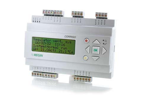
7 CE-marking Conforms with the EMC standards: CENELEC EN :2001, CENELEC EN :2001. Inputs Analogue inputs AI...Settable 0 10 V DC or PT1000, 12 bit A/D Digital inputs DI...Potential free closure Universal inputs UI...Can be set to act as either an analogue input or a digital input with specifications as above Outputs Analogue outputs AO... Settable 0 10 V DC; 2 10 V DC; 10 0 V DC or 10 2 V DC 8 bit D/A short-circuit protected Digital outputs DO... Triac outputs, 24 V AC, 0.5 A continuous Options LON... FT3150, gives a second communication route TCP/IP...Replaces RS485 for EXOline (Port 1) communication External hand terminal, E-DSP...For use with Corrigo E units without display Position of the terminals on Corrigo E Corrigo E Heating manual, revision G Chapter 2 About Corrigo E 7
8 Chapter 3 Installation and wiring 3.1 Installation Corrigo E can be mounted in a DIN-standard casing (minimum 9 modules), on a DIN-rail in a cabinet or, using a suitable front-mounting kit, in a cabinet door or other control panel. Ambient temperature: 0 50 C. Ambient humidity. Max. 95 %RH, non-condensing. 3.2 Wiring At the end of this chapter there are wiring diagrams showing the factory set configuration. We have also included blank diagrams. Since the function of most of the inputs and outputs depends on the programming of the unit the final wiring diagram cannot be filled in until the installer has decided how to use the inputs/outputs. It is important to make sure that the wiring is correctly done and in accordance with the instructions given in this manual Supply voltage 24 V AC ±15%, 50/60 Hz. 6 VA If the Corrigo E and the actuators connected to it share the same transformer it is essential that the same transformer-pole is used as reference for all the equipment. Failure to do so will prevent the equipment from functioning as intended and may also lead to damages Inputs and outputs The list of input and output functions in section is a handy instrument to help you keep track of which inputs and outputs you will need to configure. Analogue inputs Analogue inputs must refer to an A-gnd terminal placed in the same terminal block as the input being wired. Analogue inputs can, depending on the configuration, be used for either PT1000 temperature sensors or for 0 10 V DC analogue input signals, for example from a pressure transmitter. Digital inputs Digital inputs must refer to C+ on terminal 4. Digital inputs may only be wired to voltage-free contacts. Any external voltage applied to a digital input may harm the unit. Universal inputs A universal input can be configured to act as either an analogue input or as a digital input. A universal input configured as analogue input must refer to an A-gnd terminal placed in the same terminal block as the input being wired. A universal inputs configured as an analogue input can, depending on the configuration, be used for either PT1000 temperature sensors or for 0 10 V DC analogue input signals, for example from a pressure transmitter. A universal input configured as a digital input must refer to C+ on terminal 4. It may only be wired to voltage-free contacts. Corrigo E Heating manual, revision G Chapter 3 Installation and wiring 8
9 Analogue outputs Analogue outputs must refer to the A-gnd terminal placed in the AO terminal block. All analogue outputs can be individually set to any one of the following signals: 0 10 V DC 2 10 V DC 10 0 V DC 10 2 V DC If the Corrigo E and the actuators connected to it share the same transformer it is essential that the same transformer-pole is used as reference for all the equipment. Failure to do so will prevent the equipment from functioning as intended and may also lead to damages. Digital outputs Digital outputs must refer to G on terminal 10. All the digital outputs are triac controlled. The outputs will deliver 24 V AC, 0.5 A continuous. The outputs cannot be used to drive DC relays Input and output lists Use these lists during commissioning to help you keep track of which input and output functions you wish to use. Analogue inputs Analogue input signal Outdoor temperature sensor Supply temperature Heating sequence1 Tap hot water circuit 1, supply temperature Return temperature Heating sequence1 Tap hot water circuit 2, supply temperature Storage tank supply temperature Storage tank return temperature Wind-speed transmitter, 0 10 V DC Differential pressure transmitter, 0 10 V DC Supply temperature Heating sequence2 Return temperature Heating sequence2 Room temperature Heating sequence2 Room temperature Heating sequence1 Supply temperature Heating sequence3 Return temperature Heating sequence3 Room temperature Heating sequence3 Boiler temperature Corrigo E Heating manual, revision G Chapter 3 Installation and wiring 9
10 Digital inputs Digital input signal Run-indication/alarm circulation pump, P1A-HS1 Run-indication/alarm circulation pump, P1B-HS1 Run-indication/alarm circulation pump, P1A-HS2 Run-indication/alarm circulation pump, P1B-HS2 Run-indication/alarm circulation pump, P1-HW1 Volume pulses, heating usage Volume pulses, cold water usage 1 Energy pulses, heating usage Pressure switch, expansion vessel pressure External alarm Boiler alarm Run-indication/alarm circulation pump, P1A-HS3 Run-indication/alarm circulation pump, P1B-HS3 Run-indication/alarm frequency converter for pressure control Run-indication/alarm storage tank charge pump P1-HP External power limitation Volume pulses, cold water usage 2 Energy pulses, electricity meter Note: The universal inputs on Corrigo E28 can, individually, be configured as either analogue inputs using any of the analogue input signals above or as digital inputs using any of the digital input signals above. Analogue outputs Analogue output signal Valve actuator, Heating sequence1, HS1 Valve actuator, hot water circuit 1, HW1 Valve actuator, Heating sequence2, HS2 Valve actuator, Heating sequence3, HS3 Valve actuator, hot water circuit 2, HW2 Frequency converter, pressure control Split of any one of the above circuits Corrigo E Heating manual, revision G Chapter 3 Installation and wiring 10
11 Digital outputs Digital output signal Start/stop pump, P1A-HS1 Start/stop pump, P1B-HS1 Actuator HS1 increase Actuator HS1 decrease Start/stop pump, P1-HW1 Start/stop pump, P1A-HS2 Start/stop pump, P1B-HS2 Actuator HS2 increase Actuator HS2 decrease Start/stop pump, P1A-HS3 Start/stop pump, P1B-HS3 Actuator HS3 increase Actuator HS3 decrease Actuator HW1 increase Actuator HW1 decrease Actuator HW2 increase Actuator HW2 decrease Start/stop charge pump for storage tank, P1-HP1 Start frequency converter for diff pressure control Start step 1, boiler Start step 2, boiler Time channel 1 Time channel 2 Time channel 3 Time channel 4 Time channel 5 Sum alarm A Sum alarm B Sum alarm A + B Corrigo E Heating manual, revision G Chapter 3 Installation and wiring 11
12 Wiring diagram Corrigo E28 factory configuration (See also picture of the position of the terminals on page 7) 1 G 50 B Supply voltage 24 V AC, ±15%. 50/60 Hz 2 G0 51 A 3 Protective earth 52 N 4 +C +24 V DC. Reference for digital inputs DI. 53 E RS485 EXOline / Modbus 10 G Reference for digital outputs DO. 57 Net+ 11 DO1 Start/stop pump, P1A-HS1 58 Net- LON-connection (LON-versions only) 12 DO2 Start/stop pump, P1B-HS1 59 Egnd 13 DO3 Actuator HS1 increase 14 DO4 Actuator HS1 decrease 71 DI1 Run-indication/alarm pump, P1A-HS1 15 DO5 Start/stop pump, P1-HW1 72 DI2 Run-indication/alarm pump, P1B-HS1 16 DO6 Start/stop pump, P1A-HS2 73 DI3 Run-indication/alarm pump, P1A-HS2 17 DO7 Sum alarm A + B 74 DI4 Run-indication/alarm pump, P1-HW1 75 DI5 Volume pulse, heating usage meter 30 Agnd Reference pole for analogue inputs AI 76 DI6 Energy pulse, heating usage meter 31 AI1 Outdoor temperature sensor 77 DI7 Volume pulse, cold water usage 1 32 AI2 Supply temp, heating sequence 1, HS1 78 DI8 Pressure switch, expansion vessel 33 Agnd Reference pole for analogue inputs AI 34 AI3 Supply temp, hot water sequence 1, HW1 90 Agnd Reference for analogue outputs AO 35 AI4 Return temp, heating sequence 1, HS1 91 AO1 Actuator Heating sequence1, HS1 92 AO2 Actuator Heating sequence2, HS2 40 Agnd Reference pole for universal inputs UI 93 AO3 Actuator Heating sequence3, HS3 41 UI1 Supply temp, heating sequence 2, HS2 94 AO4 42 UI2 Return temp, heating sequence 2, HS2 95 AO5 43 Agnd Reference pole for universal inputs UI 44 UI3 Room sensor heating sequence 1, HS1 45 UI4 Room sensor heating sequence 2, HS2 Wiring diagram Corrigo E15H factory configuration 1 G 50 B Supply voltage 24 V AC, ±15%. 50/60 Hz 2 G0 51 A 3 Protective earth 52 N 4 +C +24 V DC. Reference for digital inputs DI. 53 E RS485 EXOline / Modbus 10 G Reference for digital outputs DO. 57 Net+ 11 DO1 Start/stop pump, P1A-HS1 58 Net- LON-connection (LON-versions only) 12 DO2 Start/stop pump, P1B-HS1 59 Egnd 13 DO3 Start/stop pump, P1-HW1 14 DO4 Sum alarm A + B 71 DI1 Run-indication/alarm pump, P1A-HS1 72 DI2 Run-indication/alarm pump, P1B-HS1 30 Agnd Reference pole for analogue inputs AI 73 DI3 Run-indication/alarm pump, P1-HW1 31 AI1 Outdoor temperature sensor 74 DI4 Pressure switch, expansion vessel 32 AI2 Supply temp, heating sequence 1, HS1 33 Agnd Reference pole for analogue inputs AI 90 Agnd Reference for analogue outputs AO 34 AI3 Supply temp, hot water sequence 1, HW1 91 AO1 Actuator Heating sequence1, HS1 35 AI4 Return temp, heating sequence 1, HS1 92 AO2 Actuator Heating sequence2, HS2 93 AO3 Actuator Heating sequence3, HS3 Corrigo E Heating manual, revision G Chapter 1 12
13 Wiring diagram Corrigo E8H factory configuration 1 G 50 B Supply voltage 24 V AC, ±15%. 50/60 Hz 2 G0 51 A 3 Protective earth 52 N 4 +C +24 V DC. Reference for digital inputs DI. 53 E RS485 EXOline / Modbus 10 G Reference for digital outputs DO. 57 Net+ 11 DO1 Start/stop pump, P1A-HS11 58 Net- 12 DO2 Start/stop pump, P1B-HS11 59 Egnd LON-connection (LON-versions only) 30 Agnd Reference pole for analogue inputs AI 71 DI1 Run-indication/alarm pump, P1A-HS1 31 AI1 Outdoor temperature sensor 72 DI2 Run-indication/alarm pump, P1B-HS1 32 AI2 Supply temp, heating sequence 1, HS1 73 DI3 Pressure switch, expansion vessel 90 Agnd Reference for analogue output AO 91 AO1 Actuator Heating sequence1, HS1 Empty wiring diagram Corrigo E28H 1 G 50 B Supply voltage 24 V AC, ±15%. 50/60 Hz 2 G0 51 A 3 Protective earth 52 N 4 +C +24 V DC. Reference for digital inputs DI. 53 E RS485 EXOline / Modbus 10 G Reference for digital outputs DO. 57 Net+ 11 DO1 58 Net- LON-connection (LON-versions only) 12 DO2 59 Egnd 13 DO3 14 DO4 71 DI1 15 DO5 72 DI2 16 DO6 73 DI3 17 DO7 74 DI4 75 DI5 30 Agnd Reference pole for analogue inputs 76 DI6 31 AI1 77 DI7 32 AI2 78 DI8 33 Agnd Reference pole for analogue inputs 34 AI3 90 Agnd Reference for analogue outputs AO 35 AI4 91 AO1 92 AO2 40 Agnd Reference pole for analogue inputs 93 AO3 41 UI1 94 AO4 42 UI2 95 AO5 43 Agnd Reference pole for analogue inputs 44 UI3 45 UI4 Corrigo E Heating manual, revision G Chapter 1 13
14 Empty wiring diagram Corrigo E15H 1 G 50 B Supply voltage 24 V AC, ±15%. 50/60 Hz 2 G0 51 A 3 Protective earth 52 N 4 +C +24 V DC. Reference for digital inputs DI. 53 E RS485 EXOline / Modbus 10 G Reference for digital outputs DO. 57 Net+ 11 DO1 58 Net- LON-connection (LON-versions only) 12 DO2 59 Egnd 13 DO3 14 DO4 71 DI1 72 DI2 30 Agnd Reference pole for analogue inputs 73 DI3 31 AI1 74 DI4 32 AI2 33 Agnd Reference pole for analogue inputs 90 Agnd Reference for analogue outputs AO 34 AI3 91 AO1 35 AI4 92 AO2 93 AO3 Empty wiring diagram Corrigo E8H 1 G 50 B Supply voltage 24 V AC, ±15%. 50/60 Hz 2 G0 51 A 3 Protective earth 52 N 4 +C +24 V DC. Reference for digital inputs DI. 53 E RS485 EXOline / Modbus 10 G Reference for digital outputs DO. 57 Net+ 11 DO1 58 Net- 12 DO2 59 Egnd LON-connection (LON-versions only) 30 Agnd Reference pole for analogue inputs 71 DI1 31 AI1 72 DI2 32 AI2 73 DI3 90 Agnd Reference for analogue outputs AO 91 AO1 Corrigo E Heating manual, revision G Chapter 1 14
15 Chapter 4 Commissioning General Before the Corrigo can be used it must be configured, inputs and outputs must be assigned and all relevant parameters must be set. All commissioning can be done using the Corrigo front panel display and buttons or using the display unit E-DSP. Corrigo E-tool The best way however, is to configure the Corrigo E by using Corrigo E-tool. Corrigo E-tool is a PC-based configuration program specially developed to simplify the commissioning of the Corrigo E-series. When using E-tool the whole configuration and all settings can be done on the computer and then downloaded to the Corrigo. An infinite number of different configurations can be saved in computer memory for later use. 4.1 How to do it? For configuration using E-tool, see the E-tool manual. For configuration using the front panel there are two ways to go depending on how much help you need. Option 1: Jump straight to chapter 6 and 7, Display, buttons and LEDs and Access rights. After mastering the button and menu system, connect power to your Corrigo, log on at System level and go to the menu Configuration. For the time being, skip the configuration menu Inputs/Outputs and start by configuring Control functions. Run through the configuration menus in order and set whatever functions and parameters you wish to include. Use chapter 4 of this manual for reference. Keep track of which inputs and outputs you will need. To help you, there is a list of input and output functions provided in chapter 3, (3.2.3 Input / Output list.) Finally, configure Inputs/Outputs. Exit Configuration and go to Settings Set the control values in Settings Set the clock and scheduler functions in Timers. Set the control setpoints in Actual/Setpoint. Your Corrigo should now be ready to run. Option 2: Read this manual in the order given below: The manual has been designed to act as a guide through the commissioning. The last chapters of the manual, not listed below, cover menus and functions that are not used during commissioning. Corrigo E Heating manual, revision G Chapter 4 Commissioning 15
16 Functional description Start by reading the chapter 5. Functional description below. Some functions are essential to the working of the unit and must be included. Others are more of the nature of optional extras which can be excluded. At the end of each function description there is a table of the necessary inputs and outputs to implement the function. At the end of the manual there is a list of all the analogue and digital inputs and outputs. As you read, mark in the list the inputs and outputs you will be using for the application you are building. Note that the universal inputs in Corrigo E28 can, individually, be configured as either analogue or digital inputs. Display, buttons and LEDs Read chapter 6 on how to use the front panel buttons to navigate the Corrigo E menu system. Access rights Chapter 7. Learn how to log in on the Corrigo E. Configuration Chapter 8. Configuration. Connect power to the Corrigo. Using the buttons and menu system, go through the configuration menus covering the functions you wish to use. On delivery the units already have the inputs and outputs assigned to various functions. These can, of course, be changed. In chapter 3 Installation and wiring there are two sets of wiring diagrams, one set showing the pre-configured input / output configuration and one set where you can fill your own configuration choices. Settings Set the control parameters, P-band, I-time for the temperature control loops in use. Set the alarm parameters; alarm levels and delay times. Timer settings Set the clock and calendar functions Setpoints Set all the setpoints for all active control loops. Hand/Auto Learn to use manual control. Very useful for testing out your system. Corrigo E Heating manual, revision G Chapter 4 Commissioning 16
17 Chapter 5 Functional description 5.1 Heating systems General Corrigo E can be configured for 1 to 3 heating systems (radiator groups), HS1, HS2 and HS Controllers The heating system controllers are PI-controllers with settable P-band and I-time Control curves The controllers have individual outdoor temperature / supply temperature control curves. Each curve has 8 fix points. The default setting of the outdoor temperature values for the fix points are -20, -15, -10, -5, ±0, +5, +10, +15. These can not be changed using the Corrigo front panel but can be changed using E-tool. The corresponding supply temperature values are settable using the front panel or E-tool Adaptation of curves Room sensors can be used to correct the control curves. The average room temperature error over 24 hours is calculated. Values 1 hour before and 1 hour after a day/night or night/day change-over are ignored. The curves are corrected once daily using the average room temperature error and a settable correction factor. The correction will be a parallel displacement of the entire curve using the following formula: Displacement = (Room setpoint - Average temp)*factor Pump control Each system can have single or double pumps. Double pumps are run one at a time with automatic, weekly change over and automatic start of the backup pump on malfunction of the active pump. Outdoor temperature dependent pump stop can be configured. Pumps are exercised for 5 minutes at 3 pm daily Frost protection If a controller is set to Off or Man(ual control) and the outdoor temperature is below a settable value a minimum, settable supply temperature will be maintained and the pump will run Wind compensation To compensate for wind chilling it is possible to connect a wind sensor and generate a setpoint displacement according to a settable factor ( C per m/s). Corrigo E Heating manual, revision G Chapter 5 Functional description 17
18 5.1.7 Building inertia and boost The building inertia is settable to one of three levels: None, Medium, High. The set inertia dictates the influence of outdoor temperature. With no inertia, the outdoor temperature is used directly, with medium inertia a one-hour average is used and with high inertia a 12-hour average is used. Boost is used to speed up the raising of the indoor temperature when switching from night set back temperature to normal comfort temperature. This is done by temporarily displacing the supply temperature set-point curve. The following conditions must be met: Average outdoor temperature lower than 17 C Supply set-point value higher than 25 C Night set-back more than 2 C (room temperature) The displacement is calculated as follows: Displacem.=Factor*(17 - outdoor temp)*night set-back Where Factor is settable 0 10 where 0 gives no boost and 10 gives high boost. The time in minutes that boost will be active is calculated as follows: Time = 1.6*(17 - Outdoor temp) Time is limited to maximum 60 minutes Night set-back Lowering of the night temperature is set in room temperature degrees. The corresponding lowering of the supply temperature is calculated by the controller by multiplying the value by 3. The Corrigo has individual schedules for each heating system with two comfort-temperature periods per day Power limitation Using a digital input the power to the heating systems can be temporarily restricted. When activated, the setpoints are lowered by a settable factor (% relative to 20 C). The limitation applies to all configured heating systems. The limitation is calculated as below: Limited setpoint=20+(setpoint-20)*factor/100 Factor 100 gives no setpoint reduction, 0 gives full reduction to 20 C. 5.2 Tap hot water General Corrigo E can be configured for one or two tap hot-water systems HW1 and HW2. These have constant supply-temperature control Controllers The heating system controllers are PID-controllers with settable P-band, I-time and D-time Night set-back The Corrigo E has individual schedules for each hot water system with two normal-temperature periods per day. Corrigo E Heating manual, revision G Chapter 5 Functional description 18
19 5.2.4 Pump control (HW1 only) Corrigo E has a digital output signal that can be used to control the hot-water circulation pump in HW1. The pump will run according to the settings of the night set-back schedule, running during normal temperature periods and standing still during periods with reduced temperature Periodic overheating Once daily, at 02:00 am the temperature set-point can be increased to 62 C to prevent growth of Legionella bacteria. The raised set-point is maintained until the supply temperature reaches 60 C but not shorter than 1 minute and not longer than 5 minutes. If the pump is stopped it will start and run for the duration of the overheating period plus 2 minutes. 5.3 Storage tank A storage tank function can be enabled. The storage tank load pump, P1-HP1 is started depending on the storage tank supply water and return water temperatures. Loading is started if the return water temperature is lower than the set start temperature. Loading is stopped when the supply temperature is higher than the set stop temperature and the return temperature is higher than the set start temperature + the set differential. 5.4 Pressure control Corrigo E can, using an analogue output signal, control a variable speed pump to maintain a constant settable pressure. A digital output signal is available to give a start signal to the frequency converter. This output is enabled as soon as the converter control signal rises above 0.1 V. 5.5 Boiler control A simple boiler control can be enabled. When the boiler temperature falls below Start temperature 1 the digital signal Start 1 will be activated. Should the temperature fall below Start temperature 2 the digital output Start 2 will be activated. Any active outputs will be deactivated when the boiler temperature rises above the set Stop temperature. 5.6 Cold-water monitoring One or two circuits monitoring the cold-water usage can be configured each using a digital pulseinput from a water meter. The pulse constant is settable. Maximum pulse rate is 2 Hz Values The following values are calculated 24 hour usage in litres, today 24 hour usage in litres, yesterday 24 hour usage in litres, day before yesterday Lowest hourly usage in litres, today Lowest hourly usage in litres, yesterday Usage total in m 3. The value is resettable Water-flow (litres / min) Corrigo E Heating manual, revision G Chapter 5 Functional description 19
20 5.6.2 Alarms Pulse error High usage Leakage control If no pulses are detected within a settable time an alarm is activated. Setting the time to 0 inhibits the alarm function. If the daily usage is higher than a settable value an alarm is activated. If the lowest hourly usage during the previous day is higher than a settable value an alarm is activated. 5.7 Energy monitoring One digital pulse function can be configured for heating energy monitoring. The pulse constant is settable Usage values The following usage values are calculated: 24 hour usage in kwh, today 24 hour usage in kwh, yesterday 24 hour usage in kwh, day before yesterday Total usage in kwh or MWh. The value is resettable Power values Heating power is calculated by measuring the time between the energy pulses. The following power values are calculated: Instantaneous value for a certain time or after a certain number of pulses Average of the above instantaneous value for the last hour Maximum value for the above instantaneous value Leakage monitoring Once a week, the control valves will be closed and the energy usage measured for a preset time. An alarm is generated if the energy leakage is larger than a settable value, default 3000 W. The time for and duration of the leakage monitoring is settable. Default is Sundays at 2:00 am for 30 minutes Alarms Pulse error High usage If no pulses are detected within a settable time an alarm is activated. Setting the time to 0 inhibits the alarm function. If the daily usage is higher than a settable value an alarm is activated. 5.8 Electricity meter One digital pulse function can be configured for electricity energy monitoring. The pulse constant is settable Usage values Total usage in MWh. The value is resettable. Corrigo E Heating manual, revision G Chapter 5 Functional description 20
21 5.9 Timer channel outputs Up to 5 digital outputs can be used as timer controlled outputs. These can be used for controlling, for example, door locks, lighting, laundry-room equipment etc. Each timer has its own scheduler with two activation periods for each day of the week and a yearbased holiday calendar Alarms Alarm handling Alarms are indicated by the alarm LED on the front. All alarms can be monitored, acknowledged and blocked using the display and buttons Alarm priorities Alarms can be given different priority levels. Digital outputs can be bound to act as alarm outputs for different priority levels. Using the front panel it is possible to change the alarm priority level (A-/B-/C-alarm/Not active) of any alarm. Corrigo E Heating manual, revision G Chapter 5 Functional description 21
22 Chapter 6 Display, LEDs and buttons This section is applicable to Corrigo E units with display and buttons but also to the hand terminal E-DSP which can be connected to Corrigo E units without display and buttons. 6.1 Display The display has 4 rows of 20 characters. It has background illumination. The illumination will normally be off but will activated as soon as any button is pressed. The illumination will be turned off again after a period of inactivity. 6.2 LEDs There are two LEDs on the front: The alarm LED marked with the symbol. The write enable LED marked with the symbol. The four LEDs placed next to the upper terminal strip will be described later. 6.3 Buttons Alarm Left Alarm LED Write LED Up Right OK C Down There are seven buttons: 4 arrow buttons which will be called UP, DOWN, RIGHT and LEFT. The menus in the Corrigo E are organized in a horizontal tree structure. The UP / DOWN-buttons are used to move between menus at the present menu level. The RIGHT / LEFT buttons are used to move between menu levels. When changing parameters the UP / DOWN buttons are used to increase / decrease the value of the parameter and the RIGHT / LEFT buttons to move between digits within the parameter. The OK button is used to confirm the choice of a parameter setting. The C button is used to abort an initiated parameter change and restore the original value. The ALARM button, marked with a red button top, is used to access the alarm list. Corrigo E Heating manual, revision G Chapter 6 Display, LEDs and buttons 22
23 6.4 Navigating the menus The start display, the display normally shown, is at the root of the menu tree. Pressing DOWN will move you through the menu choices at this, the lowest level. UP will move you back through the choices. To enter a higher menu level, use UP or DOWN to place the display marker opposite the menu you wish to access and press RIGHT. If you have sufficient log on privileges the display will change to the menu you have chosen. At each level there may be several new menus through which you may move using the UP / DOWN buttons. Sometimes there are further submenus linked to a menu or menu item. This is indicated by an arrow symbol at the right-hand edge of the display. To choose one, use RIGHT again. To back down to a lower menu level, use LEFT. Change parameter In some menus there are parameters that can be set. This will be indicated by the LED flashing. To change a parameter, first press the OK button. A cursor will appear at the first settable value. If you wish to change the value, do so by pressing the UP / DOWN buttons. In numbers containing several digits you can move between the digits using the LEFT / RIGHTbuttons. When the desired value is displayed press OK. If there are further settable values displayed the cursor will automatically move to the next one. To pass a value without changing it, press RIGHT. To abort a change and return to the initial setting, press and hold the C-button until the cursor disappears. Corrigo E Heating manual, revision G Chapter 6 Display, LEDs and buttons 23
24 Chapter 7 Access rights There are 3 different log on levels, System level which has the highest authority, Operator level and the basic no-log on level. System level gives full read / write access to all settings and parameters in all menus. Operator level gives read-only access to all settings and parameters and write access to all settings and parameters in all menus except Configuration. The basic level permits read-only access to all settings and parameters. Repeatedly press down-arrow when the start-up display is shown until the arrow-marker to the left of the text-list points to Access rights. Press right-arrow. Log on Log off Change password 7.1 Log on Log on Enter password:**** Actual level:none In this menu it is possible to log on to any level by entering the appropriate 4-digit code. The log on menu will also be displayed should you try to gain access to a menu or try to do an operation requiring higher authority than you have. Press the OK-button and a cursor marker will appear at the first digit position. Repeatedly press the up-arrow until the correct digit is displayed. Press the right-arrow to move to the next position. Repeat the procedure until all four digits are displayed. Then press OK to confirm. After a short while the text on the line: Present level will change to display the new log on level. Press left-arrow to leave the menu. 7.2 Log off Use this menu to log off from the present level to the basic "no-log on" level. Log off? No Actual level:system Logoff is also initiated automatically 5 minutes after the last time a button is pressed. 7.3 Change password As default Corrigo comes with the following passwords for the different levels: System 1111 Operator 3333 Basic 5555 You can only change the password for log on levels lower or equal to the presently active level, i. e. if you are logged in as System you can change all passwords, but as Operator you can only change the Operator and Basic passwords. There is no point in changing the Basic password since access to that level is granted automatically to all users. Corrigo E Heating manual, revision G Chapter 7 Access rights 24
25 Change password for level:operator New password: **** 7.4 Forgotten your password? If the password for System has been changed and then lost, a temporary password can be obtained from Regin. This code is date dependent and only valid for one day. Corrigo E Heating manual, revision G Chapter 7 Access rights 25
26 Chapter 8 Configuration Start by logging on at System level. See section Access rights above. Using DOWN, set the display marker opposite the menu-title Configuration and press RIGHT. The main configuration menu will be shown. Inputs/Outputs HS Supply Return temp Pump stop Twin/Single pump Run ind/motor prot Actuator type Actuator run time Actuator exercise Leakage monitoring Pulse inputs Alarm config. Other params System 8.1 In- and Outputs Analogue inputs Digital inputs Universal inputs Analogue outputs Digital outputs General Free configuration Any control signal can be bound to any input/output, the only restriction being that digital signals cannot be bound to analogue inputs and vice versa. It is up to the user doing the binding to make sure that activated functions are bound to appropriate signals. Delivery setting On delivery all the physical inputs and outputs have already been bound to a signal. The delivery settings are suggestions only and can easily be changed Analogue inputs AI Analogue input 1 Sign: Outdoortemp Raw value: 18.3 Compensation: 0.0 C All analogue inputs are for PT1000 or 0-10 Volts. Input signals can be compensated for example for wiring resistance. The Raw value will show the actual uncompensated input value. If an input has been assigned to pressure control the following submenu will be available: AI2 Pressure at 0V: 0.0 kpa 10V: 10.0 kpa Filter factor: 0.2 Corrigo E Heating manual, revision G Chapter 8 Configuration 26
27 8.1.2 Digital inputs DI Digital input 1 NO/NC: NO Signal: HS1-PumpA Status: Off To simplify adaptation to external functions, all digital inputs can be configured to be either normally open, NO, or normally closed, NC. The inputs are as standard normally open, i. e. if the input is closed, the function connected to the input in Corrigo is activated Universal inputs UI On the largest hardware version, E28 there are universal inputs. These can individually be configured as either analogue inputs or as digital inputs. When configured as analogue inputs they can be bound to any of the analogue signals described under Analogue signals. When configured as digital inputs they can be bound to any of the digital signals described under Digital signals. Universal input 1 Choose AI or DI sign AI sign: HS2 Supply DI sign: Not active After choosing AI or DI signal (the unused alternative must be set to Not active) there is a sub-menu with settings used when the input is configured as an AI-input. This menu is accessed by pressing RIGHT. Universal AI1 Sign: HS2 Supply Raw value:38.5 Compensation: 0.0 C Input signals can be compensated for example for wiring resistance. The Raw value will show the actual uncompensated input value. If an input has been assigned to pressure control the following submenu will be available: UAI1 Pressure at 0V: 0.0 kpa 10V: 10.0 kpa Filter factor: 0.2 Universal DI1 NO/NC: NO Signal: HS1-PumpA Status: Off To simplify adaptation to external functions, all universal inputs configured as digital inputs can be set as either normally open, NO, or normally closed, NC. The inputs are as standard normally open, i. e. if the input is closed, the function connected to the input in Corrigo is activated Analogue outputs Analogue outputs are 0 10 V DC. Analogue output 1 Sign: HS1 Actuator Auto Value: 2.3 V Corrigo E Heating manual, revision G Chapter 8 Configuration 27
28 8.1.5 Digital outputs Digital output 1 Signal: HS1-PumpA Auto Status: On 8.2 HS Heating System, supply Parallel displacement To each of the set control curves can be added a parallel displacement. Parallel displacemnt HS1: 0.0 C HS2: 0.0 C HS3: 0.0 C Maximum limit A maximum supply temperature can be set individually for each heating system. Maximum limit HS1: 98 C HS2: 98 C HS3: 98 C Minimum limit A minimum supply temperature can be set individually for each heating system. Minimum limit HS1: 0 C HS2: 0 C HS3: 0 C Auto-correction of setpoint Room sensors can be used to correct the control curves. The average room temperature error over 24 hours is calculated. Values 1 hour before and 1 hour after a day/night or night/day change-over are ignored. The curves are corrected once daily using the average room temperature error and a settable correction factor. The correction will be a parallel displacement of the entire curve using the following formula: Displacement = (Room setpoint - Average temp)*factor Auto-correction Setpoint HS1 On Corr. factor HS1 2.0 Present correction 0.6 C Corrigo E Heating manual, revision G Chapter 8 Configuration 28
29 8.3 Return water temperature Individual maximum and minimum return water temperatures can be set for the heating systems. Should the water temperature go outside the set limits the supply water temperature will be adjusted to correct. The adjustment will be the temperature offset multiplied by the set limiting factor Maximum temperature Max. return temp. HS1:Active HS2:Inactive HS3:Inactive Max. return temp HS1: 50 C HS2: 50 C HS3: 50 C Minimum temperature Min. return temp. HS1:Active HS2:Inactive HS3:Inactive Min. return temp HS1: 0 C HS2: 0 C HS3: 0 C Limiting factor Return limit factor. HS1: 1.00 HS2: 1.00 HS3: Pump stop Each heating system has individual day and night stop temperatures. An active circulation pump will stop if the outdoor temperature is higher than the set value and there is no heating demand. The pump will start if the temperature falls below the set stop temperature less the set hysteresis. Night is between 00:00 am and 05:00 am. All pumps, even resting twin-pumps, are exercised once daily for 5 minutes at 3 pm. Pump stop HS1:On Temp stop day: 17 C Temp stop night 17 C Hysteresis: 2.0 C Corrigo E Heating manual, revision G Chapter 8 Configuration 29
30 8.5 Twin pump / Single pump Each heating system can be configured for either a single pump or twin pumps. When twin pumps are configured, the pumps are alternated weekly on Tuesdays at 10:00 am. On activation of the pump alarm for the active pump the Corrigo will automatically switch to the other pump. Twin/Single pump HS1: Twin pumps HS2: Single pump HS3: Single pump 8.6 Run indication/motor protection Inputs are used either for indication of the motor running or for monitoring of motor protection contacts. Run indication input should be normally closed. Open contact when the motor is running, i.e. motor control output is activated, will generate an alarm. Motor protection should be normally open. Closed contact when the motor is running, i.e. motor control output is active, will generate an alarm. Run ind/motor prot HS1: Motor prot HS2: Motor prot HS3: Motor prot Run ind./motor prot HW1: Motor prot HP1: Motor prot Freq.Con: Motor prot 8.7 Actuator type Choose output signals to the actuators connected to the analogue control outputs: 0 10 V DC, 2 10 V DC, 10 0 V DC or 10 2 V DC. Actuator type HS1: 0-10V HS2: 0-10V HS3: 0-10V Actuator type HW1: 0-10V HW2: 0-10V Freq: 0-10V Note that although many manufacturers state 0 10 V DC as control signal, for many actuators the actual control signal is more often than not 2 10V DC. Check the actuator documentation carefully. If uncertain, choose 0 10V DC. Although control might be less accurate, it will ensure that the valve always can be driven to its fully opened and fully closed positions. 8.8 Running time, 3-pos. actuators These parameters have no function if analogue actuators are configured. The values are used to determine the control parameters for 3-position actuators. It is important to set correct values since incorrect values lead to sloppy control. Corrigo E Heating manual, revision G Chapter 8 Configuration 30
31 Actuator run time HS1: 255 sec HS2: 255 sec HS3: 255 sec Actuator run time HW1: 80 sec HW2: 80 sec 8.9 Valve exercising The valves can be exercised once daily. Default time is 3:00 pm but can be set to any time. The actuators will be forced to either endpoint for the set actuator running time. The pumps will run and the temperature offset alarm will be blocked for the duration of the exercising. Actuator exercise HS1: Off Hour for exerc.: 15 Minute for ex.: Leakage monitoring Once a week, the control valves will be closed and the energy usage measured for a preset time. An alarm is generated should the energy leakage be larger than a settable value, default 3.0 kw. The time for and duration of the leakage monitoring is settable. Default is Sundays at 2:00 am for 30 minutes. Leakage mon:off Weekday:Sunday Hour: 2 Duration: 30 min Permitted leakage 3.00 kw Start monitoring now No 8.11 Pulse inputs Energy pulse heating kwh/pulse Volume pulse heating 10.0 liters/pulse Cold water liters/pulse Cold water liters/pulse Electric meter kwh/pulse Corrigo E Heating manual, revision G Chapter 8 Configuration 31
32 8.12 Alarm configuration Permits configuration of all alarms. Select the appropriate alarm number (from the alarm list). The alarm text for the alarm will be displayed and the alarm priority can be set: A-alarm, B-alarm, C-alarm or not active. Alarm no (1-65): 1 Malfunction P1A-HS1 Malfunction P1A-HS1 Priority: B-alarm Alarm list Values in the Priority column show the factory set values. Alarm text Pri Description 1 Malf. P1A-HS1 B Malfunction pump P1A-HS1 2 Malf. P1B-HS1 B Malfunction pump P1B-HS1 3 Malf. P1A-HS2 B Malfunction pump P1A-HS2 4 Malf. P1B-HS2 B Malfunction pump P1B-HS2 5 Malf. P1A-HS3 B Malfunction pump P1A-HS3 6 Malf. P1B-HS3 B Malfunction pump P1B-HS3 7 Malf. Frequenc B Malfunction frequency converter 8 Malf. P1-HWC A Malfunction pump P1-HWC 9 Malf. P1-VVB - Malfunction pump P1-VVB 10 Exp. vessel A Expansion vessel alarm 11 External alarm A External alarm 12 Boiler alarm A Boiler alarm 13 Deviation HS1 A Supply temp HS1 deviates too much from the setpoint for too long. 14 Deviation HS2 A Supply temp HS2 deviates too much from the setpoint for too long. 15 Deviation HS3 A Supply temp HS3 deviates too much from the setpoint for too long. 16 Deviation HWC1 A Supply temp HWC1 deviates too much from the setpoint for too long. 17 Deviation HWC2 A Supply temp HWC2 deviates too much from the setpoint for too long. 18 Sensor error B Malfunction of a connected sensor 19 High HWC1 B HWC1 temperature too high 20 High HWC2 B HWC2 temperature too high 21 Boiler high B Boiler temperature too high 22 Boiler low B Boiler temperature too low 23 Pulse error volume B No pulses from water volume meter 24 Pulse error energy B No pulses from energy meter 25 High cold water B 24 hour cold water usage higher than limit 26 High energy B 24 hour energy usage higher than limit Corrigo E Heating manual, revision G Chapter 8 Configuration 32
33 Alarm text Pri Description 27 High cold water/hour B Cold water usage / hour higher than min. limit 28 High leakage B Leakage higher than set value 29 Malf. P1A&B-HS1 A Malfunction both circulation pumps P1A and P1B in HS1 30 Malf. P1A&B-HS2 A Malfunction both circulation pumps P1A and P1B in HS2 31 Malf. P1A&B-HS3 A Malfunction both circulation pumps P1A and P1B in HS3 32 Pulse error CW1 B No pulses from cold water meter Pulse error CW2 B No pulses from cold water meter HS1 manual C HS1 in manual mode 35 HS2 manual C HS2 in manual mode 36 HS3 manual C HS3 in manual mode 37 HWC1 manual C HWC1 in manual mode 38 HWC2 manual C HWC2 in manual mode 39 Press. manual C Pressure control in manual mode 40 Boiler manual C Boiler in manual mode 41 P1A-HS1 manual C P1A-HS1 in manual mode 42 P1B-HS1 manual C P1B-HS1 in manual mode 43 P1A-HS2 manual C P1A-HS2 in manual mode 44 P1B-HS2 manual C P1B-HS2 in manual mode 45 P1A-HS3 manual C P1A-HS3 in manual mode 46 P1B-HS3 manual C P1B-HS3 in manual mode 47 P1-HWC1 manual C P1-HWC1 in manual mode 48 P1-HWC2 manual C P1-HWC2 in manual mode 49 P1-Freq. Manual C P1- frequency controlled in manual 50 HS1 Supply max B HS1 supply temp maximum limit activated 51 HS2 Supply max B HS2 supply temp maximum limit activated 52 HS3 Supply max B HS3 supply temp maximum limit activated 53 HS1 Supply min B HS1 supply temp minimum limit activated 54 HS2 Supply min B HS2 supply temp minimum limit activated 55 HS3 Supply min B HS3 supply temp minimum limit activated 56 HS1 Return max B HS1 return temp maximum limit activated 57 HS2 Return max B HS2 return temp maximum limit activated 58 HS3 Return max B HS3 return temp maximum limit activated 59 HS1 Return min B HS1 return temp minimum limit activated 60 HS2 Return min B HS2 return temp minimum limit activated 61 HS3 Return min B HS3 return temp minimum limit activated 62 HS1 Frost B HS1 frost protection active 63 HS2 Frost B HS2 frost protection active 64 HS3 Frost B HS3 frost protection active 65 Battery error B Malfunction of the internal memory-backup battery Corrigo E Heating manual, revision G Chapter 8 Configuration 33
34 8.13 Other parameters A collection of different parameters that did not fit into any of the other menus Building inertia and boost For detailed information, see Building inertia and boost. The building inertia is settable to one of three levels: None, Medium or High. The displacement is calculated as follows: Displacem.=Factor*(17 - outd. temp)*night set-back Where Factor is a settable factor 0 10 where 0 gives no boost and 10 gives maximum boost. Boost duration time is calculated as below: Time=1.6*(17 - outdoor temp) Building inertia None Boost factor (0-10) Power limitation Using a digital input the power to the heating systems can be temporarily restricted. When activated, the setpoints are lowered by a settable factor (% relative to 20 C). The limitation applies to all configured heating systems. The limitation is calculated as below: Limited setpoint=20+(setpoint-20)*factor/100 Power limitation 100% rel +20 C Factor 100 gives no setpoint lowering, 0 gives full lowering to 20 C Frost protection If the controller is in mode Off or Manual and the outdoor temperature falls below a settable value, a settable, minimum supply temperature will be maintained. Circulation pumps will be activated. Frost protect.:off Outdoor temp activ. Frost prot:0.0 C Min sup. temp:10.0 C Split of output signal Any one of the temperature control output signals HS1, HS2, HS3, HWC1 or HWC2 can be split in two. Split of any temp sequence: No split Corrigo E Heating manual, revision G Chapter 8 Configuration 34
Corrigo E - User Manual Heating
 Corrigo E - User Manual Heating User manual Corrigo E Heating... 3 1. About Corrigo E... 3 2. Installation and wiring... 5 3. Commissioning... 10 4. Functional description... 11 5. Display, LEDs and buttons...
Corrigo E - User Manual Ventilation
 Corrigo E - User Manual Ventilation DISCLAIMER The information in this manual has been carefully checked and is believed to be correct. Regin however, makes no warranties as regards the contents of this
Corrigo E. Second generation which contains all applications and languages
 revision 05 2009 Corrigo E Second generation which contains all applications and languages The controllers in the Corrigo E series are intended for applications within heating, boiler and ventilation control
Copyright AB Regin, Sweden, Corrigo E manual Ventilation application
 Copyright AB Regin, Sweden, 2013 Corrigo E manual Ventilation application DISCLAIMER The information in this manual has been carefully checked and is believed to be correct. Regin however, makes no warranties
Corrigo E - manual Ventilation application
 Corrigo E - manual Ventilation application DISCLAIMER The information in this manual has been carefully checked and is believed to be correct. Regin however, makes no warranties as regards the contents
Sauter flexotron 800 ventilation Manual
 Manual P100012082 Table of contents DISCLAIMER The information in this manual has been carefully checked and is believed to be correct. Fr. Sauter AG however, makes no warranties as regards the contents
WE TAKE BUILDING AUTOMATION PERSONALLY MANUAL CORRIGO
 WE TAKE BUILDING AUTOMATION PERSONALLY MANUAL CORRIGO Copyright AB Regin, Sweden, 2016 DISCLAIMER The information in this manual has been carefully checked and is believed to be correct. Regin however,
Copyright AB Regin, Sweden, Corrigo manual Ventilation application
 Copyright AB Regin, Sweden, 2014 Corrigo manual Ventilation application DISCLAIMER The information in this manual has been carefully checked and is believed to be correct. Regin however, makes no warranties
Corrigo E User Guide. Heating application
 Corrigo E User Guide Heating application Copyright AB Regin, Sweden, 2011 About this user guide This user guide covers all the models in the Corrigo E series used with the heating application. The document
SAUTER flexotron800 V2 Ventilation V3.3. manual P P
 SAUTER flexotron800 V2 Ventilation V3.3 manual 2/175 Content Content 1 Generell notes 9 1.1 Disclaimer 9 1.2 Trademarks 9 1.3 Safety information 9 1.3.1 Mandatory note 9 1.3.2 General note 10 1.4 Notes
Corrigo E Ventilation
 Corrigo E Ventilation Modbus communication guide Contains the most commonly used variables. Covers all versions of Corrigo E Ventilation from 3.2 The challenger in building automation Revision: 2 Date:
flexotron800 SAUTER flexotron800 V2 Heating user program User guide P P /36 P
 SAUER V2 Heating user program User guide /36 2/36 Contents Contents About this user guide 5. Disclaimer 5.2 rademark 6.3 Safety information 6.3. Compulsory note 6.3.2 General note 6.4 Information on using
Optigo OP10 Manual. Copyright AB Regin, Sweden, 2007 R E A D Y - S T E A D Y - G O
 O P T I G O Optigo OP10 Manual Copyright AB Regin, Sweden, 2007 R E A D Y - S T E A D Y - G O DISCLAIMER The information in this manual has been carefully checked and is believed to be correct. Regin however,
Installation Guide. ECL Comfort 210, application A Table of Contents
 1.0 Table of Contents 1.0 Table of Contents... 1 1.1 Important safety and product information..................... 2 2.0 Installation... 4 2.1 Before you start.....................................................
ECL Comfort 110, application 116
 Operating Guide ECL Comfort 110, application 116 (valid as of software version 1.08) English version www.danfoss.com How to navigate? Adjust temperatures and values. Switch between menu lines. Select /
Weather compensated flow temperature control of heating and boiler systems
 Instructions ECL Comfort 110 Application 130 Weather compensated flow temperature control of heating and boiler systems User guide, Installation & Maintenance DH-SMT/DK VI.KT.G3.02 Danfoss 06/2008 How
SAUTER flexotron 800 Ventilation application User Guide
 SAUTER flexotron 800 Ventilation application User Guide P100012091 1 Table of content P100012091 2 Table of content Table of content Table of content... 2 1 About this user guide... 4 2 About flexotron
ECL Comfort 110, application 130
 Operating Guide ECL Comfort 110, application 130 (valid as of software version 1.08) English version www.danfoss.com How to navigate? Adjust temperatures and values. Switch between menu lines. Select /
Corrigo E User Guide. Ventilation application
 Corrigo E User Guide Ventilation application Copyright AB Regin, Sweden, 2009 About this user guide This user guide covers all the models in the Corrigo E series used with the ventilation application.
Pre-programmed room controller with communication
 revision 02 2016 RC-C3 Pre-programmed room controller with communication RC-C3 is a complete pre-programmed room controller from the Regio Midi series intended to control heating and cooling in a zone
C66. ECL Comfort. User's Guide. Installer's Guide. ECL Comfort C66. User's Guide. Installer's Guide. *vi7cc502* *087R8069* *087R8069* *vi7cc502*
 User's Guide VI.7C.C5.02 2005.09 C66 *vi7cc502* *087R8069* www.danfoss.com ECL Comfort User's Guide ECL Comfort Installer's Guide www.danfoss.com *087R8069* *vi7cc502* Mixing controller with PI controlled
Pre-programmed room controller with communication and hidden setpoint
 revision 02 2016 RC-C3H Pre-programmed room controller with communication and hidden setpoint RC-C3H is a complete pre-programmed room controller from the Regio Midi series intended to control heating
Operating Guide. ECL Comfort 210 / 296 / 310, application A247 / A Table of Contents
 1.0 Table of Contents 1.0 Table of Contents... 1 1.1 Important safety and product information..................... 2 2.0 Installation... 6 2.1 Before you start.....................................................
1 DOCUMENT REVISION CONTROL ELEMENTS... 9
 CONTENTS Contents 1 DOCUMENT REVISION... 8 2 SOFTWARE VERSION... 8 3 BASIC DESCRIPTION... 8 4 CONTROL ELEMENTS... 9 4.1 BASIC DISPLAYS...10 4.2 CONTROL KEYS...11 4.2.1 Rotary button (Press / Turn)...11
P20. ECL Comfort. User's Guide. Installer's Guide. ECL Comfort P20. User's Guide. Installer's Guide *VI7BD502* *087R8014* *087R8014* *VI7BD502*
 User's Guide VI.7B.D5.02 2005.10 P20 *VI7BD502* *087R8014* www.danfoss.com ECL Comfort User's Guide ECL Comfort Installer's Guide www.danfoss.com *087R8014* *VI7BD502* Boiler controller P20 VI.7B.D5.02
Pre-programmed room controller with communication
 revision 01 2011 RC-C Pre-programmed room controller with communication RC-C is a complete pre-programmed room controller from the Regio Midi series intended to control heating and cooling in a zone control
C37. ECL Comfort. User's Guide. Installer's Guide. ECL Comfort C37. User's Guide. Installer's Guide *VI7CE602* *087R8070* *087R8070* *VI7CE602*
 User's Guide VI.7C.E6.02 2005.09 C37 *VI7CE602* *087R8070* www.danfoss.com ECL Comfort User's Guide ECL Comfort Installer's Guide www.danfoss.com *087R8070* *VI7CE602* Mixing controller with ON / OFF controlled
Odyssey. issue 01c. system manual
 dyssey issue 01c system manual SYSTEM MANUAL Table of Contents Technical Specification 1 Summary of Features 2 General Description 3 Control ptions 4 Description of Main Features 5 Control Schemes 6 Installation
Dryer Controller M720
 User Manual Dryer Controller M720 Hardware version 2.00 Software version 2.00 Manual M720 Dryer controller Page 1 of 60 Document history Preliminary version: - Created in April, 2009 Hardware Version 2.00,
C User manual
 C10...40 User manual Introduction COORIGO is a completely new range of controllers which has been designed to be easy to use and operate. The controllers have a display and built in panels for operation
Manual for the integration in BMS/GTC
 Manual for the integration in BMS/GTC Communication parameters MODBUS RTU and BACNET COMMUNICATION UTBS PRO-REG Software Version 3.6 EN ÍNDEX 1. GENERALITIES...2 1.1. Introduction...2 1.2. signals types...2
user s manual VUBMG102
 user s manual CONTROL SYSTEM DHP-R VUBMG102 2 Danfoss VUBMG102 Contents 1 Introduction... 5 2 Functional description... 7 2.1 Heating... 7 2.1.1 Primary supply temperature...7 2.1.2 Integral control...7
RVL471 Heating and Domestic Hot Water Controller Basic Documentation
 RVL471 Heating and Domestic Hot Water Controller Basic Documentation Edition: 2.2 Controller series: C CE1P2524E 23.10.2002 Siemens Building Technologies HVAC Products 2/118 HVAC Products 23.10.2002 Contents
C62. ECL Comfort. User's Guide. Installer's Guide. ECL Comfort C62. User's Guide. Installer's Guide *VIKME102* *087R8091* *087R8091* *VIKME102*
 User's Guide VI.KM.E1.02 2005.09 C62 *VIKME102* *087R8091* www.danfoss.com ECL Comfort User's Guide ECL Comfort Installer's Guide www.danfoss.com *087R8091* *VIKME102* Double mixing controller C62 VI.KM.E1.02
User Manual. Dryer Controller M720
 User Manual Dryer Controller M720 Hardware version 1.00 Software version 1.00 Preliminary version Manual M720 Dryer controller Page 1 of 42 Document history Preliminary version: - Created in April, 2009
M3092 Programmer. User s Manual. M3096B-33 E Copyright 2017 SELCO
 User s Manual Copyright 2017 SELCO SELCO Betonvej 11 - DK-4000 Roskilde Denmark Phone: 45 7026 1122 - Fax: 45 7026 2522 e-mail: selco@selco.com www.selco.com Table of contents 1 INTRODUCTION...4 2 SOFTWARE
OJ Waterline control system
 OJ Waterline control system THERMOSTATS FOR COMFORT HEATING AND SNOW MELTING Product presentation Mk3 It s all about Room Temperature Control! The essential main goals are: Comfort Flexibility Reliability
Watts Under Floor Multi-zone Controller User Manual
 Watts Under Floor Multi-zone Controller User Manual Master unit RF Timer The digital wall thermostat can also use a floor temperature sensor to control minimum and maximum floor temperature, as well as
Operation manual. Daikin Altherma ground source heat pump EGSQH10S18AA9W. Operation manual Daikin Altherma ground source heat pump.
 English Table of contents Table of contents About this document About the system. Components in a typical system layout... 3 Operation 3 3. Overview: Operation... 3 3. The user interface at a glance...
C-series Controllers for air handling systems
 C-series Controllers for air handling systems Corrigo, C-series, is a range of digital controllers for air-handling systems designed to be easy to use and operate, having a large capacity, and a high degree
EBC20. Instructions for fitting, installation and operation. Read and save these instructions!
 EBC20 UK Instructions for fitting, installation and operation Read and save these instructions! 2 3002878 EBC20 UK 290415 1. Product information............................................... 4 1.1 Delivery.............................................................
USER MANUAL S203. Controller for three circuits. - control for 2 heating circuits - 1 domestic hot water control. Saving energy, creating comfort
 USER MANUAL S203 Controller for three circuits - control for 2 heating circuits - 1 domestic hot water control Saving energy, creating comfort This user manual consists of two parts. Issues that are intended
Heating and D.h.w. Controller RVL482 Basic Documentation
 Heating and D.h.w. Controller RVL482 Basic Documentation Edition: 1.0 Controller series: A CE1P2542en 20.05.2008 Building Technologies Siemens Switzerland Ltd Building Technologies Group International
OUMAN EH-800 Heating controller USER MANUAL
 OUMAN EH-800 Heating controller USER MANUAL 1 EH-800 is a heating controller for private homes and business facilities having heating systems with circulating water. An extension unit can be obtained as
ECL Comfort V a.c. and 24 V a.c.
 230 V a.c. and 24 V a.c. Description and application In heating applications the can be integrated with the Danfoss Link solution via the DLG interface for use in single-family applications. The controller
Replaceable LED modules. Sleep or unattended mode. Auto-silence and auto-acknowledge
 Replaceable LED modules 11 Alarm Sequences as per ISA-18.1 standard Each channel/window fully field programmable RS232 or RS485 MODBUS-RTU communication Repeat relay for each window and multifunction relays
Operation manual. Daikin Altherma ground source heat pump EGSQH10S18AA9W. Operation manual Daikin Altherma ground source heat pump.
 EGSQH0S8AA9W English Table of contents Table of contents About this document About the system Components in a typical system layout Operation Overview: Operation The user interface at a glance Buttons
Operation manual. Daikin Altherma low temperature monobloc EBLQ05CAV3 EBLQ07CAV3 EDLQ05CAV3 EDLQ07CAV3
 EBLQ05CAV3 EBLQ07CAV3 EDLQ05CAV3 EDLQ07CAV3 English Table of Contents Table of Contents 1 About this document 2 2 About the system 2 2.1 Components in a typical system layout... 2 3 Operation 3 3.1 Overview:
Operation manual. Daikin Altherma Low temperature split EHBH04CBV EHBH08CBV EHBH11CBV EHBH16CBV
 EHBH04CBV EHBH08CBV EHBH11CBV EHBH16CBV EHVH04S18CBV EHVH08S18CBV EHVH08S26CBV EHVH11S26CBV EHVH16S26CBV English Table of contents Table of contents 1 About this document 2 2 About the system 2 2.1 Components
EXPERT TRI-STAR. Temperature controller. User s Manual
 Temperature controller r s Manual WARNINGS The warranty can be void if this product is used in a manner not specified by the manufacturer. Every effort has been made to ensure that this manual is complete,
Topvex SX/C, Topvex TX/C Air Handling Unit
 Topvex SX/C, Topvex TX/C Air Handling Unit Operation and Maintenance Instructions Document in original language 131678 A003 GB Contents 1 Warnings...1 2 Product Description...2 2.1 Internal components...2
Topvex SF02-SF12 Air Handling Unit
 Topvex SF02-SF12 Air Handling Unit Installation instructions Document in original language 130324 A004 GB Copyright Systemair AB All rights reserved E&OE Systemair AB reserves the rights to alter their
ModSync Sequencing System Installation & Operation Manual. For use with Fulton Steam Boilers.
 ModSync Sequencing System Installation & Operation Manual For use with Fulton Steam Boilers. Revision 3.0 8/21/2008 - 2 - Table of Contents Introduction Page 4 Features Page 4 Sequence of Operation Page
ECL Comfort V a.c. and 24 V a.c.
 230 V a.c. and 24 V a.c. Description and application The controller is designed for easy installation: one cable, one connector. The controller has a customdesigned display with backlight. For a quick
ProCon 16, 31, 47 & 75. RVA 63 Boiler and Circuit Controller Commissioning Data.
 ProCon 16, 31, 47 & 75. RVA 63 Boiler and Circuit Controller Commissioning Data. The RVA63 controller can be utilized to control the following system configurations via LPB communication. Equipment Required
Installation Manual Tracker 221
 Installation Manual Tracker 221 KSR KUEBLER AG Im Kohlstatterfeld 17 D-69439 Zwingenberg / Germany www.ksr-kuebler.com Contents About this Installation Manual...4 Description Tracker 220-series...4 Installing
RVL471. Heating controller. G2524en. Installation Instructions. 1 Installation. 2 Commissioning
 G2524en Heating controller Installation Instructions RVL471 1 Installation 1.1 Place of installation In a dry room, e.g. the boiler room Mounting choices: In a control panel (on the inner wall or on a
The ECL Comfort 110 is a universal 1-circuit controller for use in district heating substations and district heating systems as well as boilerbased
 Data sheet ECL Comfort 110 230 V a.c. and 24 V a.c. Description and application ECL Comfort 110 The ECL Comfort 110 is a universal 1-circuit controller for use in district heating substations and district
Topvex SR03, SR04, SR06 Compact Air Handling Unit
 Compact Air Handling Unit GB GB Corrigo ver. no. 1.2-1-00 Manufacturer Our products are manufactured in compliance with applicable international standards and regulations. Systemair AB Industrivägen 3
Two-Channel Gas Controller
 Two-Channel Gas Controller Specifications subject to change without notice. USA 09 Page of DESCRIPTION Highly configurable, UL 0 performance-tested and -certified, and wall-mounted gas monitor; continuously
VERSO-P, VERSO-R Series Air Handling Units with C3 Control System Electrical Installation and Operation Manual
 VERSO-P, VERSO-R Series Air Handling Units with C3 Control System Electrical Installation and Operation Manual EN Table of Contents 1. INSTALLATION MANUAL...3 1.1. Air Handling Units Sections Connection...3
RVL481. Heating Controller. including d.h.w. heating
 2 541 Heating Controller including d.h.w. heating RVL481 Multifunctional and communicating heating controller for use in residential and non-residential buildings. Suited for heating circuit control with
Temperature Controller CC24-7 UNIBOX USER S MANUAL Legion Dr. Mason, MI USA October 2010 Ph. (517) Fax (517)
 Fax (517)") 3 4 Temperature Controller USER S MANUAL Aerotech, Inc. FORM: QM1386 4215 Legion Dr. Mason, MI 48854-1036 USA October 2010 Ph. (517) 676-7070 Fax (517) 676-7078 FOR CUSTOMER USE Enter the serial number
3 4 Temperature Controller USER S MANUAL Aerotech, Inc. FORM: QM1386 4215 Legion Dr. Mason, MI 48854-1036 USA October 2010 Ph. (517) 676-7070 Fax (517) 676-7078 FOR CUSTOMER USE Enter the serial number
ProCon 16, 31, 47, 75, 77 & HT. RVA 46. Zone Controller Commissioning Data.
 ProCon 16, 31, 47, 75, 77 & HT. RVA 46. Zone Controller Commissioning Data. The RVA 46 Zone Controller can only be used in conjunction with a RVA47 controlled boiler installation. The RVA46 controller
Operation and Maintenance Instructions
 Compact Air Handling Unit Operation and Maintenance Instructions Item# 415005 2015-06-23 Contents 1 Warnings...1 2 Product Description...1 2.1 Internal Components Topvex TR800-4000...1 2.2 Description
Manual# User s Manual. 200E Series. DCU 210E/208E Diesel Engine Control Unit RP 210E Remote Panel
 Manual# 1006494 User s Manual 200E Series DCU 210E/208E Diesel Engine Control Unit RP 210E Remote Panel User's Manual Rev. 1.0 Marine Pro 200E Series ~~~ DCU 210E Diesel Engine Control Unit DCU 208E Diesel
Owner s Manual. Part Number 33CS250-01
 33CS Commercial Programmable Thermostat IMPORTANT: Read entire instructions before programming the thermostat. Owner s Manual Part Number 33CS250-01 GENERAL Carrier s 7-day, commercial, programmable thermostats
Operation manual. Daikin Altherma Low temperature split EHBH04CB EHBH08CB EHBH11CB EHBH16CB EHBX04CB EHBX08CB EHBX11CB EHBX16CB
 EHBH04CB EHBH08CB EHBHCB EHBH6CB EHBX04CB EHBX08CB EHBXCB EHBX6CB EHVH04S8CB EHVH08S8CB EHVH08S6CB EHVHS8CB EHVHS6CB EHVH6S8CB EHVH6S6CB EHVX04S8CB EHVX08S8CB EHVX08S6CB EHVXS8CB EHVXS6CB EHVX6S8CB EHVX6S6CB
RVP360 and RVP361 Heating controllers for 2 heating circuits and d.h.w. Basic Documentation
 RVP360 and RVP361 Heating controllers for 2 heating circuits and d.h.w. Basic Documentation Edition 1.0 Controller series A CE1P2546en 15.03.2011 Building Technologies Siemens Switzerland Ltd Industry
Topvex SR 09, 11, Topvex TR Compact Air Handling Units
 Topvex SR 09, 11, Topvex TR 09-15 Compact Air Handling Units Operation and Maintenance Instructions Document in original language 125594 A004 GB Copyright Systemair AB All rights reserved E&OE Systemair
HMC300. Control unit. Operating Instructions. EMS plus (2014/10) O
 O") HMC300 Control unit EMS plus 6 720 808 471-00.1O Operating Instructions 6 720 813 192 (2014/10) Contents Contents Key to symbols and safety instructions................3 1.1 Key to symbols...........................
HMC300 Control unit EMS plus 6 720 808 471-00.1O Operating Instructions 6 720 813 192 (2014/10) Contents Contents Key to symbols and safety instructions................3 1.1 Key to symbols...........................
ECL Comfort 210 controller, Remote Control Units ECA 30 / 31 and Application keys
 ECL Comfort 210 controller, Remote Control Units ECA 30 / 31 and Application keys Designed in Denmark Description ECL Comfort 210 controller series ECL 210 The ECL Comfort 210 is an electronic weather
CELLTROL II BIOREACTOR CONTROL SYSTEM OPERATIONS MANUAL
 Operation Manual Celltrol II Bioreactor Control System Page 1 of 33 Table of Contents 1) Introduction... 3 1.1) Scope of Document... 3 1.2) Control System Overview... 3 1.3) Introduction to Celltrol II...
ECL Comfort 300 / V a.c. and 24 V a.c.
 Data sheet ECL Comfort 300 / 301 230 V a.c. and 24 V a.c. Application The ECL Comfort 300 / 301 is an electronic temperature controller which can be loaded with selected applications by means of an ECL
No part of this publication may be reproduced, stored in an automated data file or made public in any form or by any means, whether electronic,
 No part of this publication may be reproduced, stored in an automated data file or made public in any form or by any means, whether electronic, mechanical, by photocopying, recording or in any other manner
HIGH EFFICIENCY FIRETUBE CONDENSING GAS BOILER
 This manual must be left with owner and should be hung on or adjacent to the boiler for reference. US HIGH EFFICIENCY FIRETUBE CONDENSING GAS BOILER MODELS CHS-85 through CHS-399 APPENDIX A CONTROLLER
MAKING MODERN LIVING POSSIBLE. TP7001 Range Electronic 7 Day Programmable Room Thermostat. User Guide. Danfoss Heating
 MAKING MODERN LIVING POSSIBLE TP7001 Range Electronic 7 Day Programmable Room Thermostat Danfoss Heating User Guide TP7001 Electronic 7 Day Programmable Room Thermostat For a large print version of these
ECL Comfort 310 controller, Remote Control Units ECA 30 / 31 and Application keys
 ECL Comfort 310 controller, Remote Control Units ECA 30 / 31 and Application keys Designed in Denmark Description ECL Comfort 310 controller series ECL 310 The ECL Comfort 310 is an electronic weather
Installer Manual KNX Touchscreen Thermostat
 Installer Manual 02952 KNX Touchscreen Thermostat Index GENERAL FEATURES AND FUNCTIONALITY from page 5 ETS PARAMETERS AND COMMUNICATION OBJECTS from page 7 COMMUNICATION OBJECTS GENERAL FEATURES AND FUNCTIONALITY
RVL480. Heating Controller
 2 540 Heating Controller RVL480 Multifunctional and communicating heating controller for use in residential and non-residential buildings. Suited for heating circuit control, boiler temperature control
ECL Comfort 210 controller, Remote Control Units ECA 30 / 31 and Application keys Designed in Denmark
 ECL Comfort 210 controller, Remote Control Units ECA 30 / 31 and Application keys Designed in Denmark Description ECL Comfort 210 controller series The ECL Comfort 210 is an electronic weather compensated
Installation Guide. ECL Comfort 310, application A Table of Contents
 1.0 Table of Contents 1.0 Table of Contents... 1 1.1 Important safety and product information..................... 2 2.0 Installation... 5 2.1 Before you start.....................................................
Boiler controller S-Tronic Plus
 Operating Instructions Boiler controller S-Tronic Plus Version 50.0 - Build 05.0 Translation of the original German operating instructions for technicians and operators Read and follow the instructions
ER65-DRW Controller. Heating Applications. Product Bulletin. Heating Controller
 PB_ER65-DRW_ 202 ER65-DRW Controller Heating Applications Product Bulletin The controller is a digital device for domestic or residential heating units. It covers water and air heating applications. All-in-one
Universal Monitoring System. Model IMEC8A. User Manual Version 1.10 Software version 2.3.1
 Unit 7/8, Heathrow Causeway Estate, Ariel Way, Hounslow Middlesex, TW4 6JW +44 (0) 208 6302270 www.cpcuk.co.uk Universal Monitoring System Model IMEC8A User Manual Version 1.10 Software version 2.3.1-1
I/A Series 716C 1/16 DIN Temperature Controller
 Product Specifications I/A Series 716C 1/16 DIN Temperature Controller PSS 2C-1B5 A The Foxboro 716C is a powerful compact, 1/16 DIN, microprocessor-based temperature controller that offers a variety of
N M AirControl AHU. Control manual
 N 10.63 M 03-2016 AirControl AHU Control manual EN CONTENTS PAGE 1 - MONITORING AND CONTROL 2 1.1 The program 2 1.2 The HMI terminal 2 1.3 The controller 4 1.4 Description of the air handling units 4
G a
 G2474 74 319 0081 0 a en Installation Instructions Heating controllers RVP3... Installation Place of installation In a dry room, e.g. in the boiler room Mounting choices: Control cabinet (in the front,
AHU Control. Operating Instructions V5.00
 1177fil HHFlex C/R/P/S AHU Control Operating Instructions V5.00 Contents 1 SAFETY CONSIDERATIONS 5 1.1 General 5 1.2 Avoid Electrocution 5 1.3 Abbreviations used 5 2 CONTROLLER DESCRIPTION 6 2.1 Overview
Rooftop Thermostat Controller Specification and Installation Instructions. Model TRT2422
 ºF / º C Rooftop Thermostat Controller Model TRT2422 Description The TRT2422 is a combination controller and thermostat with a built-in scheduler, which is designed for simple and accurate control of single
District heating controller for two heating circuits and d.h.w. according to Siemens specifications:
 4 319 2984 0 G2384en en Installation Instructions District heating controller for two heating circuits and d.h.w. RVD240 Installation Place of installation In a dry room, e.g. in the heat exchanger room
PowerLogic ION Setup Meter Configuration Software Configuration Guide
 PowerLogic ION Setup Meter Configuration Software Configuration Guide 70002-0293-03 12/2010 Conventions Used in this Manual This section describes the symbols and terminology used in this guide. Symbols
DPC-1 Programmable digital thermostat with communication Versión 2.0. Technical Information. Ref: N
 DPC-1 Programmable digital thermostat with communication Versión 2.0 Ref: N-27360 1108 Technical Information I S O 9 0 0 1 ER-0028/1991 Johnson Controls Manufacturing España, S.L. is participating in the
SYX660 Commissioning Guide V Page 1 of 55
 Page 1 of 55 Table of Contents 1. INTRODUCTION... 4 1.1 Important Information Regarding Product Safety... 5 1.2 Notes on Disposal... 5 1.3 INPUTS... 6 1.4 ANALOGUE OUTPUTS... 7 1.5 OUTPUTS... 7 1.6 WEB
Condensing Boiler RS100 Controller Training Program
 Condensing Boiler RS100 Controller Training Program Training Program #501102A 062311 www.rinnai.us 2009 Rinnai America Corporation Features and Benefits The RS100 connects directly to the boiler and acts
Wallace & Tiernan Controllers & Analysers ChemTrim Disinfection Controller
 Wallace & Tiernan s & Analysers ChemTrim Disinfection Introduction The ChemTrim Disinfection is a modern, dedicated controller incorporating the latest advanced electronics and process control application
ENERGY LIGHT USER S GUIDE ENERGY LIGHT USER S GUIDE
 ENERGY LIGHT USER S GUIDE Release January 2001 CONTENTS 1.0 GENERAL CHARACTERISTICS... 4 1.1 MAIN CHARACTERIS TICS... 4 2.0 USER INTERFACE (CODE C5121230)... 5 2.1 DISPLAY... 5 2.2 MEANING OF THE LEDS...
User Guide
 ABS control panel CP 112 212 ON ON ON ON ON ON User Guide www.absgroup.com ii ABS CONTROL PANEL CP 112 212, USER GUIDE Copyright 2008 ABS Group. All rights reserved. This manual, as well as the software
Application description
 Application description Application description Hersteller KNX Touch Control Hager Displays Touch Displays ETS Touch Control Order number Product designation Application programme TP product SWDT03 WDT030
Syncro AS. Analogue Addressable Fire Control Panel. User Manual
 Syncro AS Analogue Addressable Fire Control Panel User Manual Man-1100 Issue 02 Nov. 2008 Index Section Page 1. Introduction...3 2. Safety...3 3. Panel Controls...4 3.1 Access Level 1...4 3.2 Access Level