CODE COMPLIANCE MANUAL
|
|
|
- Emery Myles Robinson
- 5 years ago
- Views:
Transcription

1 5 County Complex Court Suite 160 Prince William, VA Phone: CODE COMPLIANCE MANUAL Supplemental Information intended for Architects, Engineers, Designers, and Installers 2012 Edition USBC & SFPC Prince William County Fire Marshal s Office Code Compliance Manual 6/28/2016
2 Preface This document has been prepared as a service to architects, engineers, designers, and installers of fire protection systems to provide basic information on the codes, policies, and requirements of Prince William County Fire Marshal s Office (FMO). The information provided represents the current minimum requirements of the FMO on new construction of buildings, installation and modification of fire protection systems, and other fire prevention related issues commonly encountered at the time of its writing and does not represent all of the building and fire code requirements enforced. The requirements set forth in this document should not be considered to be all inclusive, as application of the State and County Fire Prevention Code and other nationally recognized codes and recommended practices is constantly being evaluated and modified when found necessary. The information provided for fire protection plan submissions is provided for reference only. Each fire protection system installed or modified is required to comply with all applicable codes and standards as provided in the Uniform Statewide Building Code and Virginia Statewide Fire Prevention Code in place at the time of installation or modification. Questions concerning the information contained within this manual should be directed to the Prince William County Fire Marshal s Office at Page 2
3 Table of Contents Applicable Codes and Standards 4 Plan Submittal Chart 5 Fire Alarm System Fire Protection Plan Submission Minimum Requirements 6 Fire Alarm Express Permits 7 Automatic Fire Sprinkler System Fire Protection Plan Submission Minimum Requirements 8-9 Sprinkler Express Permits 10 Sprinkler System Water Supply Submission Requirements 11 Fire Pump Calculation Submission Requirements 11 Standpipe Calculations 12 Underground Fire Main Fire Protection Plan Submission Minimum Requirements Commercial Kitchen Hood Protection Plan Submission Minimum Requirements 15 Emergency Repair Permit 16 Fire Protection Plan Review Process & Walk Thru Process Fire Protection Systems Flow Chart 18 Fire Protection System Acceptance Inspections After Hours (Overtime) Inspections 24 Minimum Requirements for a Stocking Approval (148) 25 Minimum Requirements for an FMO Final-Tenant Approval (149) Fire Protection Permit Plan Review Fee Schedule 28 Inspection Fee Schedule 29 Inspection Fee Collection Packages Fire Lane Plans- Minimum Submission Requirements 32 Fire Lane Markings and Signs Fire Hydrant Coverage and Location Fire Flow 35 Emergency Vehicle Access Site Requirements for Buildings Under Construction 36 Electronic Access Gate Signage Key Box Repository Requirements 40 Hydrostatic Testing of Automatic Sprinkler System Tenant Work Policy 41 Fire Alarm Testing Policy For Non High-Rise Buildings Installation of Pressure Reducing/Regulating Valves on Standpipes 44 Sprinkler Protection in Elevator Hoist Ways and Machine Rooms 45 Fire Protection and Life Safety Procedures in Buildings Under Construction and Renovation Placing Fire Protection systems In-Service or Out-Of-Service 48 Fire Watch 49 High-Rise Fire Control System Requirements Page Page 3
4 Applicable Codes and Standards 1. Prince William County Design and Construction Standards Manual 2. Virginia Uniform Statewide Building Code State edition which includes, but is not limited to the following: Virginia Construction Code (VCC) 2012 ICC International Mechanical Code 2012 ICC International Plumbing Code 2012 National Electrical Code Virginia Statewide Fire Prevention Code 2012 edition which includes the International Fire Prevention Code 2012 with Virginia and Prince William County amendments 4. National Fire Protection Association (NFPA) standards most commonly used that are referenced by the USBC or SFPC are as follows: NFPA 10 (2010) Portable fire extinguishers NFPA 12A (2009) Halon 1301 fire extinguishing systems NFPA 13 (2010) Installation of sprinkler systems NFPA 13D (2010) Installation of sprinkler systems in one and two-family dwellings and mobile homes NFPA 13R (2010) Installation of sprinkler systems in residential occupancies up to four stories in height NFPA 14 (2010) Standpipe and hose systems NFPA 16 (2011) Deluge foam-water sprinkler systems and foam-water spray systems NFPA 17 (2009) Dry chemical extinguishing systems NFPA 17A (2009) Wet chemical extinguishing systems NFPA 20 (2010) Centrifugal fire pumps NFPA 22 (2008) Water tanks for private fire protection NFPA 24 (2010) Installation of private fire service mains and their appliances NFPA 25 (2011) Inspection, Testing & Maintenance of Water-Based Fire Protection System NFPA 30 (2012) Flammable and combustible liquids code NFPA 72 (2010) National Fire Alarm Code NFPA 80 (2010) Fire doors and windows 5. Elevator Code ASME A Accessibility Code ICC A , Accessible and Usable Buildings and Facilities Page 4
5 PLAN SUBMITTALS TYPE OF PLAN PRINCIPAL CODE SUBMIT Building (Non- High-rise) Building (Tenant) VCC PHONE SEE TO: CONTACT PAGE VCC/ Fire Prevention Code Building N/A VCC/PWC Building Development/ PWC Building Development Permits Office VCC/PWC Building Development/ PWC Building Development Permits Office PWC Building Development Permits Office PWC Building Development Permits Office PWC Building Development Permits Office Assembly / Exhibition Building (Highrise) / / / / / /6925 Fire Alarm (Highrise) VCC 907 FMO* , Fire Alarm (Non- Highrise) VCC 907 FMO* , Fire Alarm VCC 907 FMO* Tenant Fire Pump NFPA 20 FMO* Foam NFPA 11 SERIES FMO* NA Halon NFPA 12A FMO* N/A Key Box Fire Prevention Code FMO Repository Range Hood MECH CODE FMO* Site Plans PWCDCSM/VCC TBA Sprinkler NFPA 13 FMO* Sprinkler Tenant NFPA 13 FMO* Tent / Temporary VCC / Fire Prevention Code PWC Building Development Permits Office/ FMO /6925/ Note: Initial plans for Fire Marshal s Office review are to be submitted at the permit counter located at #5 County Complex Court for processing. Plans that have been reviewed by the Fire Marshal s Office will be returned to the permit counter for pick up. All plans are submitted through Building Development Plan Intake except for Fire Lane Plans (FLP) which is submitted directly to the Land Development Division during the site plan review. N/A N/A N/A N/A Page 5
6 Fire Alarm Systems Minimum Requirements for Fire Protection Permit (FPP) Submissions 1. Submit completed FPP application form with plans. FPP applications are available at the Building Development office located in the Development Services Building - #5 County Complex Court. FPP application must include the MASTER PERMIT NUMBER for the project 2. Submit a copy of current Virginia contractor s license. 3. Submit a copy of current Prince William County business license. 4. Submit a minimum of three (3) sets of detailed construction documents/shop drawings and specifications to include, but not limited to the following: Shop drawings shall be drawn to an indicated scale on sheets of uniformed size. Location and type of each fire alarm device to be installed i.e., fire alarm control panel, annunciator panel, strobes, horns, manual pull stations, duct detectors, control valve monitoring device, tamper switch monitoring device, etc. Location of devices above the finished floor, ceiling heights, etc. Proposed zoning for system if applicable, fire alarm zones shall be coordinated with sprinkler zones Location of control panels and annunciator panels A detailed sequence of operation narrative that describes the performance and function of every device in the system; this shall include auxiliary control functions such as elevator capture and recall, HVAC shutdown, Central Station notification, release of fire doors, smoke control, etc A scaled diagram of the graphic fire alarm annunciator panel (FAAP) Detailed battery calculations Wiring riser diagram; include type, gauge of wire and quantity of devices Location of fire walls and fire doors, if applicable Equipment specification sheets for all fire protection components Provide Scope of Work 5. Identify method of system supervision per the USBC. Information included on this list is intended to represent the minimum requirements for fire protection plan submissions. Each fire protection plan is required to comply with all applicable codes and standards. APPLICABLE CODES & STANDARDS 2012 Uniform Statewide Building Code NFPA 72 (2010) Page 6
7 Fire Alarm Express Permits Fire Alarm Express Permit Requirements: 1. Must obtain a fire protection permit 2. Scope of work shall be any of the following: Monitoring the sprinkler flow and tamper switches Adding a fire alarm panel One smoke detector above the FACP One alarm device on the exterior of the building 3. Fire alarm installation is still required to comply with NFPA 72; equipment listed for fire protection use is required 4. Fire inspection is required (Fire Alarm, Battery Test and Fire Alarm Final) 5. During the fire inspection, the contractor is required to provide the following, but not limited to: All fire alarm manufacturer s equipment cut-sheets A riser diagram showing the FACP and all devices The location of FACP in the sprinkler room showing that the proper clearance for the FACP Detailed battery calculations The sequence of operation Verification of the connection to the central station Note: The Fire Alarm Express Permit does not apply to existing fire alarm systems that need to modify the fire alarm panel, wireless monitoring systems, or any similar alterations. This option will be allowed for all occupancies that only need a fire alarm sprinkler monitoring system. Page 7
8 Automatic Fire Sprinkler Systems Minimum Requirements for Fire Protection Permit (FPP) Submissions 1. Submit completed FPP application form with plans. FPP applications are available at the Building Development office located in the Development Services Building - #5 County Complex Court. FPP application must include the MASTER PERMIT NUMBER for the project. 2. Submit a copy of current Virginia contractor s license. 3. Submit a copy of current Prince William County business license. 4. Submit a minimum of three (3) complete sets of detailed construction documents/shop drawings to include, but not limited to the following: Shop drawings shall be drawn to an indicated scale on sheets of uniformed size. Sufficient detail to document the hazard classification; warehouse projects should provide a detailed letter describing the storage arrangement, the commodity classification, intended storage height of each commodity, whether there is fixed rack storage, dimensions of the rack/shelving including the vertical flues, spacing between aisles, etc. High-piled combustible storage buildings are required to comply with Chapter 32 of the 2012 Edition of the SFPC. Cross-sectional details for sloped ceilings, attic roofs, stairways, elevation changes, (floor to floor and overall height dimensions of the building), etc. Also provide details for potential obstructions such as bulk heads, ceiling fans, surface mounted lights, half height walls, etc. Hydraulic calculations for most demanding area(s); all hydraulic reference nodes must be clearly delineated on the plan including the reference points to the water supply source Show the sprinkler zones and align them with fire alarm zones, if applicable Water supply data must be within one-year period and available water supply shall be adjusted to low hydraulic gradient. Note: Water supply data is available from the Prince William County Service Authority (PWCSA) and water supply data for most of the Dale City area can be obtained from the Virginia American Water Company Location, size, and type of all pipe to be installed including sprinkler fittings Location, size, and type of all sprinkler heads to be installed; sprinkler legend shall include symbol, type, model no., finish, temperature classification, orifice size, K-factor, thread size, manufacturer, escutcheon and quantity of each type and dimensions for sprinkler coverage (for residential application) Spacing requirements, obstruction to sprinkler discharge requirements, etc Riser detail showing all devices including backflow preventer and FDC interconnection Details for hangers / fastener methods and locations (including trapeze style) The use of sammy screw hanger installation methods shall have an engineer s certification from the truss manufacturer when connecting hangers into engineered open wood web joist systems. Location of all control valves and inspector s test valves Pipe volume calculations for dry systems Provisions for off-site monitoring and valve supervision Page 8
9 Identify the location and rating of fire walls, fire separation walls, fire partitions, etc Submit equipment specification sheets for all fire protection components For residential applications, identify the sprinkler spacing requirements on the plans such as distances from surface lighting, air returns, fire places, ovens, heat diffusers, fire place flue piping, washer/dryer, water heater, furnace, etc in accordance with the manufacturer s equipment listing. Sidewall sprinkler heads are required on the top floor and no sprinkler piping shall be located in areas subjected to temperatures less than 50 F i.e., attic spaces, garage ceilings, and exterior walls. CPVC piping will follow minimum spacing requirements where the pipe is concealed and exposed to a heat source The minimum distance from heat producing sources shall be as follows: 18 for hot air flues and uninsulated heat ducts; 12 for uninsulated hot water pipes; and 6 from water heater or furnace unless otherwise specified by manufacturer s equipment specifications. Special consideration will be given for areas that will not permit such distances and will be evaluated on a case by case basis. 5. Submit a copy of the PWC approved site plan i.e., approved by the Land Development and other related details including, but not limited to the locations of fire hydrants and underground fire mains. Information included on this list is intended to represent the minimum requirements for fire protection plan submissions. Each fire protection plan is required to comply with all applicable codes and standards. APPLICABLE CODES & STANDARDS 2012 Uniform Statewide Building Code NFPA 14 (2010 edition) / 22 (2008 edition) NFPA 13 / 13R / 13D / 20 (2010 edition) NFPA 25 (2011 edition) / 30 (2012 edition) Page 9
10 Sprinkler Express Permits *** For Mercantile & Business Use Groups with Construction Modifications Up to 10 Sprinkler Heads or Less. This process is intended to save owners/contractors time since they would not need to draw and submit sprinkler plans for relatively minor sprinkler modifications such as mercantile and business facilities that need a quick plan review turn around time for new tenants that require minor changes to the tenant space such as relocating a wall or adding a restroom. Big box mercantile stores qualify if the sprinkler system was initially properly designed and installed. The sprinkler type and K- factor needs to be the same. There should not be extensive sections of pipe being added off the cross-mains. Relatively short lengths of pipe added to the system should be reasonably acceptable. If the scope of work does not meet the criteria below, the contractor must submit complete plans for the work. The following criteria apply: FPP permit is required Sprinkler plans showing scope of work are required during the inspections. Scope of work must be clearly defined on the permit- Adding or relocating how many heads (also show it on the plans) Reason for sprinkler modification i.e., adding office wall, etc. Add or relocate a combined total of 10 heads or less; sprinkler head(s) must be the same i.e., same type, K-factor, temperature, style, orifice, etc Sprinkler installation must comply with NFPA 13 The sprinkler head spacing is required to be consistent with the existing design. No modification to the sprinkler cross-mains or risers is allowed. Sprinkler pipe must be consistent with the existing design. New hangers shall comply with the spacing requirements in NFPA 13. Fire protection system inspections are still required. *** If the guidelines for this permit process are not met, the customer will be required to submit plans to the FMO for review. Page 10
11 Sprinkler System Water Supply Submission Requirements All automatic sprinkler hydraulic designs submitted to the Fire Marshal s Office must provide for the following: 1. Flow test data for an on-site hydrant, provided by and attested to the water supplier providing water service, with date of flow test. The date of the flow test must be within one (1) year of the submittal date. If an on-site hydrant is not available for the test, the closest available hydrant shall be used. 2. The elevation and street location of the test hydrant. 3. An adjusted water supply curve for the test hydrant shall be based on the low hydraulic grade line as provided by the water supplier. High and low hydraulic grade lines shall be obtained from the water supplier and shall be referenced to a specific date. Adjustment of the water supply curve at the test hydrant by use of the low hydraulic grade. The calculation shall consist of adjusting the entire water supply curve by subtracting the highest slab elevation (HSE) from the hydraulic grade converting the difference to PSI. i. Example: S = 97, R = 30, Q = 800, ii. HSE 400 feet iii. Low H.G.L. = 600 feet iv = 200 feet = or 87 PSI v. Hence use S = 87, R = 20, Q = 800 as design curve at test hydrant location. 4. A minimum safety factor of (5 PSI) below the (adjusted) water supply curve must be provided. This safety factor will not necessarily accommodate all potential increases in water supply requirements due to tenant fit outs. Final responsibility for a long and short term system adequacy rests with the designer/contractor/installer. Fire Pump Calculation Submission Requirements In all buildings requiring fire pumps, a set of fire pump calculations will be required to be submitted to the Fire Marshal s Office. The calculations must show that sufficient pressure is available to provide support of the fire protection system being served. The calculation must show that 20 PSI is available at the suction side of the fire pump while the pump is operating at 150 percent of its rated capacity. Fire pump calculations must take into account the low Hydraulic Gradient Line for the site and show that the fire protection system demand is under the fire pump test curve. Page 11
12 Standpipe Calculation Requirements To perform calculations for standpipes required by USBC, two sets of calculations are necessary to determine riser piping sizes, supply piping and the water service piping. According to USBC 905 and NFPA 14 (2010), the size of the supply piping to the standpipes must be sized to allow a minimum flow of 500 GPM for the first riser and 250 GPM for each additional riser up to a total of 1250 GPM. A residual pressure of 100 PSI needs to be maintained at the top most outlet of each riser while flowing the minimum quantities of water shown above. In fully fire suppressed non hi-rise buildings the 100 PSI need not be maintained but is to be replaced with the fireman's hose demand pressure required at the top most outlet of each riser. For standpipes in buildings of 150 or more standpipes must be supplied by an on-site fire pump. The fireman s hose is to be supplied by the pumper having a pump curve using the following pressures and flows at the FDC: GPM, GPM, and GPM. Note: Sprinkler calculations still need to be submitted along with these calculations. Sprinkler and standpipe calculations must take into account the low HGL for the site and come in under the water supply curve. Page 12
13 Underground Fire Mains Minimum Requirements for Fire Protection Permit (FPP) Submissions 1. Submit completed FPP application form with plans. FPP applications are available at the Building Development office located in the Development Services Building - #5 County Complex Court FPP application must include the MASTER PERMIT NUMBER for the project 2. Submit a copy of current Virginia contractor s license. 3. Submit a copy of current Prince William County business license. 4. Submit a minimum of three (3) copies of the PWC approved site plan i.e., approved by the Land Development (which will have a perforated stamp) and other related details to include, but not limited to the following: a. Designate the Scope of Work i.e., the portion of pipe being installed i.e., from the street to within 5 of the building; from 5 within the building to the flange; the entire fire line, etc b. Location of the underground fire line; type and size of all pipe to be installed c. Show the depth of cover for underground fire lines which shall have at least 42 of compacted soil cover measured from the top of the pipe. Loose gravelly soil, rock, concrete, asphalt or similar is not considered part of the required depth of cover. d. Mega-lugs and/or thrust blocking is for all piping e. Equipment specification sheets for all fire protection components f. Cross section showing entire length of the underground fire main relative to any exposure (e.g. storm water, sanitary lateral, etc.) that intersects with it. g. All rods, nuts, bolts, washers, clamps, and other restraining devices shall be coated with a bituminous or other acceptable corrosion-retarding material 5. Fire lines shall be designed and installed per NFPA No valves shall be installed in fire line between street valve at water main and O.S. & Y. valve inside of building. 7. Electrical ground wires shall not be connected to underground fire lines. 8. Provide at least 36 of insulative earthen cover between the fire line and any exposure (e.g. storm water, sanitary lateral, etc.) that may subject the pipe to a temperature below 40 F and include a profile of the underground fire main with the site plan. 9. Show the location, types and quantity of fittings to be installed. Provide elevation detail of all direction changes in piping. For underground fire lines less than 6-inches in diameter, hydraulic calculations are required to determine the water supply demand and the appropriate pipe size for the sprinkler system design. Page 13
14 Information included on this list is intended to represent the minimum requirements for fire protection plan submissions for Underground Fire Mains. Each fire protection plan is required to comply with all applicable codes and standards. APPLICABLE CODES & STANDARDS 2012 Uniform Statewide Building Code NFPA 13 (2010 edition) Page 14
15 Commercial Kitchen Hood Suppression Systems Minimum Requirements for Fire Protection Permit (FPP) Submissions 1. Submit completed FPP application form with plans. FPP applications are available at the Building Development office located in the Development Services Building - #5 County Complex Court FPP application must include the MASTER PERMIT NUMBER for the project 2. Submit a copy of current Virginia contractor s license. 3. Submit a copy of current Prince William County business license. 4. Submit a minimum of three (3) sets of detailed construction documents/shop drawings to include, but not limited to the following: a. Details and dimensions of the kitchen hood, cooking appliances, exhaust duct, plenum, etc. b. Type and size of appliances must be identified c. Identify type and location of nozzles relative to each protected plenum, exhaust duct, and appliance (including the nozzle height above cooking surface) d. Location, type, and function of detecting devices including temperature classification of fusible links, etc e. Type and quantity of extinguishing agent with complete calculations and manufacturer s data sheets to determine agent quantity f. Size, length, and arrangement of extinguishing system piping g. Location of the manual means of actuation h. Required alarms including a detailed sequence of operations i. Interconnection to exhaust fan, building fire alarm, gas shut-off and electric shunt-trip must be included 5. Submit the fire suppression equipment specification manual which shows the system listing and pertinent sections that apply to the design. 6. Normal operating temperature shall be measured at the fusible link location above appliances and the appropriate link shall be selected. Provide verification of this reading at time of inspection. Information included on this list is intended to represent the minimum requirements for fire protection plan submissions. Each fire protection plan is required to comply with all applicable codes and standards. APPLICABLE CODES & STANDARDS 2012 Uniform Statewide Building Code NFPA 17 (2009) NFPA 17A (2009) Page 15
16 Fire Protection Permit for Emergency Repair According to Section of the USBC, an emergency repair can be made to a fire protection system provided that the licensed contractor proceeds to obtain an FPP permit by the end of the next day after the commencement of the repair. The Fire Marshal s Office and Development Services has created a fast track Emergency Repair permit to meet the state requirements and expedite the permit process. Currently, there is an Emergency Repair permit for fire sprinkler systems and fire alarm systems. The permit fee consists of one fire inspection. If additional fire inspections are needed, an additional fire inspection fee will be added to the permit. Fire Protection Plan Review Process The Fire Marshal s Office participates & performs fire protection plan reviews for the Planning Office, Land Development Services and Building Development Services. Fire Protection Permit Plans are submitted to the Building Development Department via Plans Intake/Permits Office as a Fire Protection Permit (FPP). Plan Intake logs in the plan and administers an FPP number. FMO staff picks up the plans on a daily basis. FMO staff logs the plan in as FMO Reviewer and places the plan in the plan review drawers. Plan reviewers review the oldest dated plan first. The 1 st review is typically reviewed within two weeks of receipt; the due date is one month from the time of receipt. Revisions are typically reviewed within one week of the re-submittal; the due date is one month of receipt. When plans are approved, we update the disposition in Energov (Permit processing computer system), file the FMO copy of the plan, and return the remaining approved plans to the Permits Office. When the plans are rejected, we contact the contractor, discuss the deficiencies in detail, and provide guidance on the process necessary for resolution. Fire Protection Plan Review Walk-Thru Process for FPP The Fire Marshal s Office provides an additional plan review service to developers and contractors to expedite the plan review process of less complicated fire protection plans. The walk-thru process allows contractors to get approved plans in the same day. The walk-thru process is held every Thursday from 8:30 a.m. to 3:30 p.m. at the Development Services Building; Permit Counter (window 17). Types of fire protection plans qualifying for a walk thru: Sprinkler modifications 40 heads or less; no hydraulic calculations Fire alarm monitoring of a sprinkler system flow & tamper switch Fire alarm plans involving 10 devices or less (note: the FACP counts as one device) Page 16
17 Fire alarm systems associated with an access-control device such as the use of magnetic locking devices Underground fire lines Range hood suppression systems Special Notes: Minor revisions must meet the above criteria Original approved plans including manufacturer cut sheets are required for reference Designer of record must be present during the plan review process All submitted plans must meet the minimum submission requirements Note: Walk-thru s are processed by appointment only. All appointments are made on a firstcome, first serve basis for the available 30 minute appointment slots. An FPP number must be obtained prior to scheduling the walk thru appointment by calling plan intake at To schedule a walk thru appointment with the FMO, or if you have additional questions, please call or FMOPlanReview@pwcgov.org Page 17
18 Fire Protection System Inspections Flow Chart Fire Alarm System Automatic Sprinkler System Standpipe System Underground Fire Main 73 Fire Alarm Dry System Wet System Residential Sprinklers (13D/13R) 75 Standpipe Visual 59 U/G Visual 74 Battery Test ** 83 Sprinkler Visual 83 Sprinkler Visual 83 Sprinkler Visual Breezeway Loop? NO YES 67 Standpipe Hydro 60 U/G Hydro 81 Fire Alarm Final Connected To Sprinkler System? NO YES * 62 Hydro Test 65 Air Test 64 Trip Test/air buildup 88 Dry System Final * 62 Hydro Test 90 Antifreeze test 72 Fire pump * 62 Hydro Test 89 2 head flow test (13D) 87 4 head flow test (13R) 66 Sprinkler Final 85 Breezeway Loop visual 84 Breezeway Loop hydro 86 Breezeway Loop flush 68 Standpipe Flow 55 Standpipe Final 61 U/G Flush 82 U/G final 71 Dry Chemical 70 Hood 69 Clean agent 58 Wet Chemical *** 148 Stocking (Optional) Fire Lane Inspection (FLP) 146 FMO Final Shell 149 FMO Final Tenant Notes concerning the inspection flow: For an 88 or 66 inspection, the U/G Fire main must have an approved 82 inspection if there was an underground fire line involved and have final approval of all sprinkler components and a 73 to get a final. An 82 inspection must have approved 59, 60, and 61 inspections to get a final. The flush may come from another permit in the case of a split permit for the street valve to 10 feet outside the building and 10 outside the building to the sprinkler flange (spool). For 146 and 149 inspections ALL fire protection systems must have been approved and finaled. A 149 cannot be scheduled until the 146 inspection for the shell (if applicable) has a status of provisional approval (PAP) or approved (APP) *Hydro only required if 1) 5 heads or more, 2) 10 or more fittings, 3) 20 or more feet of pipe, or any combination of the three. ** A fire alarm battery test may or may not be required on an existing system depending upon the scope or work being done. If the fire alarm is connected to emergency generator power a battery test is not required. *** For an optional 148 inspection, the fire protection systems (sprinkler, standpipe, and fire alarm) must be finaled. Other systems may not be required to be finaled until the 149 inspection. Shell buildings cannot have a 148 inspection done as stocking of a shell is not permitted. If stocking is not needed, the inspections proceed directly to the 149 inspection. Page 18
19 Fire Protection System Acceptance Inspections Inspections for Fire Protection Permit Plans (FPP) are conducted by Fire Marshal s Office staff during normal working hours, Monday through Friday, between the hours of 7:30 A.M. and 4:00 P.M. To request a Fire Marshals Office fire protection system or building inspection the permit holder must either 1) use the eportal by going to and enter the required information, or 2) call the IVR inspection line at and follow the prompts. Requests for inspections for the following day will not be approved after 3:00 P.M. the day prior to the inspection date requested. If you have problems using these systems call between the hours of 7:30 A.M. and 4:30 P.M. for assistance. If you are trying to cancel a scheduled inspection between the hours of 4:30 P.M., the day before, and 8 A.M., the day of the scheduled day, you must call prior to 8 A.M. of the scheduled date. Failure to do so will cause a cancellation fee to be applied. FMO fire lane inspections and stocking inspections are not available through the eportal or IVR. The permit holder must call must call , between the hours of 8:00 A.M. and 4:30 P.M. The permit holder requesting the inspection will need to provide the FLP number for fire lane inspections, or the BLD (building permit) number for stocking and storage inspections. Requests for inspections for the following day will not be approved after 3:00 P.M. the day prior to the inspection date requested. A representative of the permit holder requesting the inspection must be at the job site to meet the Fire Marshal s Office inspector at the time of the inspection. The permit holder representative must provide a copy of the fire protection permit and the fire protection plans approved by the Fire Marshal s Office at the time of the inspection, if any work was done on a fire protection system. Fire Protection Permits may require one or more of the following inspections depending upon the scope of work being done. The numbers in parenthesis indicate the inspection number used when requesting a fire protection inspection. 1. Underground Fire Main (UFM): UFM visual (59) - A visual inspection of the piping, connections, thrust blocks, threaded rods, and/or mega lug connectors from the street water valve to the base of the flange for the connection to piping of the automatic sprinkler and/or standpipe system. UFM hydrostatic test and inspection (60) - A 200 P.S.I. or 50 pounds over static water pressure, whichever is greater, hydrostatic test for a two (2) hour period of UFM components from the street water valve to the base of the flange for the connection to e the automatic sprinkler and/or standpipe system. The test pressure for a UFM connected to 13D sprinkler system is street pressure. UFM flush test and inspection (61) - A flush of the UFM piping between the street water valve and the base of the automatic sprinkler and/or standpipe system flange. This test and inspection is required for all sprinkler system water supplies. (NFPA 13, 13R, and 13D) Where there is not a separate fire protection permit number the inspection request is called in on the sprinkler fire protection permit number. Page 19
20 UFM final inspection (82) - A review of the UFM system including tests and inspection records to assure that all the required system tests/inspections on the underground fire main are code compliant and have been approved. The above tests/inspections are done in accordance with NFPA 24 (2010), Private Fire Service Mains and Their Appurtenances. The tests/inspections can be done on separate days or on the same day provided that they are performed in the proper sequence that is visual, hydrostatic, and flush. Gauges used in performing acceptance tests on fire suppression systems witnessed by the Fire Marshal s Office must meet the following criteria: The gauge shall be appropriate for the type of test; i.e., air gauge for an air pressure test, a water gauge for a hydrostatic test. Air gauges shall have increment markings of two pounds or less. Water gauges must have increment marking of ten pounds or less. The gauge shall be capable of registering pressures above the minimum pressure required during the test. (0 PSI to 300 PSI) The pressure registered during the actual test shall be at least the minimum required for the test and less than the maximum of the gauge register. Gauges must be marked as accepted by UL and/or FM testing laboratories. The test gauge(s) must zero out at the end of a test to pass the inspection. WATER FLOW RATE FOR LINE FLUSHING Pipe Size inches Flush Orifice Size inches Flow Rate gpm , , ,000 *see Section 300, Table 3-5 of the PWC DCSM (revised September 15, 2014) 2. Fire Alarm: Fire alarm (73) - A test/inspection of all fire alarm system components, including all manual and automatic activation/initiation devices, visual and audible warning devices. This is a 100% test of all devices according to the manufacturer s recommended method. The fire alarm control panel must be clear of any trouble signals (clear panel) prior to the start of this inspection. A Fire Alarm Record of Completion must be provided prior to the beginning of the test. Battery test (74) - A test/inspection of the ability of the fire alarm system to sound all visual and audible horns for five (5) minutes after the system has been on battery power for twentyfour (24) hours. Page 20
21 Fire Alarm Final (81) - A test/inspection of the entire fire alarm system installation to assure that the central station connection is on line and in service. This inspection cannot be performed until the fire alarm and fire alarm battery test inspections have passed. The above tests/inspections are done in accordance with NFPA 72 (2010), National Fire Alarm Code. The test/inspections can be done on separate dates or on two dates as long as they are done in consecutive order as shown above. 3. Fire Pump test (72) - A test of the fire pump and associated control equipment. This test will not be witnessed until 1) the underground fire main is completed and has final inspection, 2) all associated sprinkler piping, including the fire pump test header, and other components have final inspection, and 3) there is an approval by the electrical inspections division of the wiring to the fire pump driver, the fire pump controller, and secondary source of power, such as a generator and associated electrical transfer equipment (if provided). The above test/inspection is conducted in accordance with NFPA 20 (2010), Centrifugal Fire Pumps. Arrangements must be made by the contractor to supply sufficient approved equipment to conduct the necessary flow tests. 4. Automatic Fire Sprinkler: Sprinkler breezeway loop flush (86) A flush of the breezeway loop sprinkler piping and appurtenances until the water flowing from the piping is clear. Sprinkler breezeway loop visual (85) A visual examination of the breezeway loop sprinkler piping before it is concealed. All piping and other appurtenances must be readily visible for the representative of the Fire Marshal s Office to inspect from ground/floor level. Sprinkler breezeway loop hydro (84) A hydrostatic test of all components of the breezeway loop sprinkler piping and appurtenances. The test is done at 200 P. S. I. or 50 pounds over static pressure, whichever is greater, for a two (2) hour period. All piping and appurtenances must be readily visible for the representative of the Fire Marshal s Office to inspect from ground/floor level. Sprinkler hydro test/inspection (62) - A hydrostatic test of all components of the automatic fire sprinkler system, including hangers and other appurtenances. The test is done at 200 P.S.I. or 50 pounds over static pressure, whichever is greater, for a two (2) hour period. All piping and other appurtenances must be readily visible for the representative of the Fire Marshal s Office to inspect from ground/floor level. A temperature of at least 40 degrees Fahrenheit must be maintained in the area testing is being conducted. NFPA13D system shall be Hydrostatically tested at normal operational pressure Sprinkler visual (83) - A visual inspection of all components of the automatic sprinkler system, including hangers and their appurtenances. This inspection can be conducted at the same time as the sprinkler hydrostatic test when a hydrostatic test is required. All piping and hangers must be readily visible for the representative of the Fire Marshal s Office to inspect from ground/floor level. For sprinkler systems utilizing plastic piping, the Fire Marshals Office inspector will require random removal of a representative number of sprinkler heads to visually inspect the sprinkler head and confirm that excess glue has not compromised the sprinkler s ability to function. Also any installations utilizing Sammy screws, or similar Page 21
22 methods of hanging sprinkler piping, must have written documentation from the truss manufacturer or structural engineer to certify that the truss point load limits are not exceeded. Code Modification Sprinklers in Garage area We have determined that we need two visual inspections for the situation where there are pendant fire sprinklers in the residential garages. The first visual is status quo where you see the piping, hangers, etc. The second visual would be limited to the batt insulation that is tented below the pipe to prevent the cold air in the garage from freezing the sprinkler pipe. In order to get this accomplished, there is additional responsibility on our office. The benefit will be to prevent the piping in the garage from freezing, minimize code compliance issues in the future, and reduce fire department responses. To be effective the process will be as follows: 1. Code Modification is approved by the Building Department and attached to the approved fire sprinkler plans 2. The following comment will be added to the FMO approval letter: Code Modification BLD201X-XXXXX requires an additional visual fire inspection to assure the insulation is installed as specified 3. Once the plan is approved, the FPE plan reviewer will add a comment in Tidemark, An additional visual inspection for the insulation in the garage ceiling is required due to the Code Modification 4. ASC/ASAs will notify the contractor to confirm an additional visual inspection will be required 5. Fire inspectors will perform the initial visual inspection. Even if the inspection is approved, the inspection will still receive a REJ disposition with an added comment i.e., Visual for the garage is approved; okay to install insulation according to the Code Modification; 2 nd visual will be required 6. Once the insulation is installed correctly, the visual will be approved There is no additional fee charged for the additional visual, but that visual inspection will count toward their grace visual inspection. Therefore, if there are additional visual inspections needed beyond the two inspections, a fee of $ would be charged to the contractor. Sprinkler Alarm/flow (63) - A test/inspection of the automatic sprinkler system to assure proper flow rate is available at the designed flow pressure. Sprinkler trip (64) - A test/inspection of a dry pipe fire sprinkler system to assure water reaches the inspector s test valve in sufficient quantity of flow within sixty (60) seconds of opening the inspector s test valve. After successful completion of the sprinkler trip test the sprinkler system is reset and a pressure build up test of the air compressor is conducted. The air compressor must build up system air to normal pressure within thirty (30) minutes. Sprinkler Antifreeze (90) -- A test of the antifreeze solution in an automatic sprinkler system that uses antifreeze to prevent the sprinkler water from freezing. Minimum requirement is -20 degrees F. Sprinkler 2 head flow 13D (89) A flow of the equivalent of two (2) sprinkler heads on a NFPA 13D automatic sprinkler system to determine if sufficient quantity of water is available at the required design water pressure. Page 22
23 Sprinkler 4 head flow 13R (87) A flow of the equivalent of four (4) sprinkler heads on a 13R automatic sprinkler system to determine if sufficient quantity of water is available at the required design water pressure. Sprinkler air (65) - A test/inspection of the dry automatic sprinkler system utilizing 40 P.S.I. air pressure for 24 hours. Wet Sprinkler final (66) - A test/inspection of the automatic wet fire sprinkler system, including testing of all flow switches, tamper switches, and other connections that are required to be monitored. Ceiling systems must be complete and connection to the central monitoring system must be on line and in service to gain approval. This inspection cannot be performed until the all of the applicable wet sprinkler inspections/tests shown above have passed. If there is a standpipe system associated with the automatic wet sprinkler system it must pass the standpipe flow test/inspection also prior to approval of the sprinkler final. The Fire Alarm Final must be approved prior to the Wet Sprinkler Final. Prior to any connection of sprinkler piping to an underground fire main flush of the underground fire main must be witnessed by the Fire Marshal s Office. A contractor s Material and Test Certificate for Aboveground Piping must be provided at final. Dry Sprinkler final (88) - A test/inspection of the dry automatic sprinkler system including the testing of all flow switches, tamper switches, and other connections that are required to be monitored. Ceiling systems must be complete and connection to the central monitoring system must be on line and in service to gain approval. This inspection cannot be performed until the all of the applicable dry sprinkler inspections/tests shown above have passed. If there is a standpipe system associated with the automatic dry sprinkler system it must pass the standpipe flow test/inspection also prior to approval of the sprinkler final. Prior to any connection of sprinkler piping to an underground fire main flush of the underground fire main must be witnessed by the Fire Marshal s Office. A contractor s Material and Test Certificate for Aboveground Piping must be provided at final. 5. STANDPIPE: Standpipe hydro (67) - A test/inspection of all standpipe system components. The hydrostatic test is done at 200 P.S.I. or 50 pounds over static pressure, which ever is greater, for a two (2) hour period. A temperature of at least 40 degrees Fahrenheit must be maintained in the area testing is being conducted. Standpipe visual (75) An inspection of all standpipe components, including hangers and other appurtenances. All piping and hangers must be readily visible for the representative of the Fire Marshal s Office to inspect from ground/floor level. All discharges must be at the intermediate landing level. The Hydro and Visual test/inspections may be performed at the same time. Standpipe flow (68) - A test/inspection to assure that a sufficient quantity of water flow is available at the most hydraulically remote point of a standpipe system to meet the design requirements. Standpipe final (55) A test/inspection of the standpipe system including the testing of all flow switches, tamper switches, and other connections that are required to be monitored. All other standpipe inspections must be approved for the final to be approved. A contractor s Material and Test Certificate for underground Piping must be provided at final. Gauges used in performing acceptance tests on fire suppression systems witnessed by the Fire Marshal s Office must meet the following criteria: Page 23
24 The gauge shall be appropriate for the type of test; i.e., air gauge for an air pressure test, a water gauge for a hydrostatic test. Air gauges shall have increment markings of two pounds or less. Water gauges must have increment marking of ten pounds or less. The gauge shall be capable of registering pressures above the minimum pressure required during the test. (0 PSI to 300 PSI) The pressure registered during the actual test shall be at least the minimum required for the test and less than the maximum of the gauge register. Gauges must be marked as accepted by UL and/or FM testing laboratories. 6. Hood (70) - A test/inspection of the hood fire suppression system, including the dumping of the extinguishment agent, or test medium, to assure proper operation, flow, fan, and if applicable, alarm operation. Prior to scheduling this inspection any gas piping or electrical wiring to appliances located under the hood must have the final by the appropriate inspection agency (gas, mechanical, plumbing or electrical department finals). 7. Clean Agent (69) - A test/inspection of the hood fire suppression system, including the dumping of the extinguishment agent, or test medium, to assure proper operation, flow, fan, and if applicable, alarm operation. The requires that documentation of a successful integrity test, referred to as a door test, was conducted to assure that the area being protected is free from any significant air leakage that would be detrimental to the effectiveness of the clean agent being used. 8. Wet Chemical (58) - A test/inspection of the hood fire suppression system, including the dumping of the extinguishment agent, or test medium, to assure proper operation, flow, fan, and if applicable, alarm operation. Prior to scheduling this inspection any gas piping or electrical wiring to appliances located under the hood must have the final by the appropriate inspection agency (gas, mechanical, plumbing or electrical department finals). 9. FMO Final Inspection- Occupancy Evaluation (145) - An inspection to assure that an existing building or space meets all applicable codes and ordinances for occupancy by persons for permanent occupancy and operation. These inspections are coordinated through the Building Code Enforcement Office as part of the Joint Occupancy Evaluation (JOE) process. 10. FMO Final Inspection- Shell (146) - An inspection to assure that a shell building or space is complete and ready for tenant layout work to commence. After Hours (Overtime) Fire Inspections Overtime inspection(s) are limited by the availability of staff, and is a voluntary program for the FMO inspectors. The hourly charge will be in accordance with the Building Development Fee Schedule with a three (3) hour minimum for this service per permit. A minimum 1 hr travel time expense will be incurred when travel is not directly from the Fire Marshal s Office. Stocking permit inspection (148) - An inspection to assure that fire protection systems and other fire prevention code/fire protection related items, affecting a building or space, are in place and at a state of completion to allow the storage or installation of interior furnishings, such as office furniture, goods for sale, or similar items to enable an occupant to stock or install such furnishings, Page 24
25 goods, or similar materials. Approval of this inspection will result in a recommendation to the Building Official to permit stocking operations. The responsibility for final approval and issuance of a stocking permit lies with the Building Official. Minimum Requirements for Fire Marshal s Office approval for Stocking The following minimum requirements must be met in order to secure a recommendation of approval from the FMO to the Building Official for stocking of a building, tent, or other structure. Responsibility for final approval and issuance of the stocking permit lies with the Building Official. This list is not all inclusive and should be considered to be the minimum requirement. All tests/inspections for fire protection plan permits that have been issued must be completed and the installation of fire protection systems at such a stage that they will provide an acceptable degree of fire protection as determined by the Fire Marshal s Office. These inspections may include one or more of the following, depending upon the scope of fire protection system work that has been done: Underground fire main visual inspection Underground fire main hydrostatic test and inspection Underground fire main flush inspection Underground fire main final Fire pump test Sprinkler hydrostatic test and inspection Wet Sprinkler final inspection Dry Sprinkler final inspection Standpipe flow test Fire alarm inspection Fire alarm battery test inspection Fire alarm final inspection A stocking/storage permit inspection request must be made via eportal or IVR system after all of the above tests and/or inspections have been completed and approved. FMO Final inspection- Tenant (149) - An inspection to assure that a new building or new space is meets all applicable codes and ordinances for occupancy by persons for permanent occupancy and operation. Page 25
26 Minimum Requirements for a FMO Final-Tenant Inspection Approval The following requirements must be met in order to secure a recommendation of approval from the FMO to the Building Official for occupancy of a building, tent, or other structure. This list is not all inclusive and should be considered to be the minimum requirements. Approval of this inspection will result in a recommendation to the Building Official to issue a Certificate of Occupancy. Responsibility for final approval and issuance of the Certificate of Occupancy permit lies with the Building Official. All fire protection plans that have been approved must have the associated fire inspection/test approved by the Fire Marshal s Office prior to the FPP permit being finaled and final approval issued. These inspections may include one or more of the following, depending upon the scope of fire protection system work that has been done: Underground fire main visual, fire main hydrostatic test, and fire main flush inspections Underground fire main final Sprinkler hydrostatic test and inspection Wet Sprinkler final inspection Dry Sprinkler final inspection Hood system inspection (suppression chemical dump test) Fire alarm inspection Fire alarm battery test inspection Testing of all elevators for compliance with fireman s recall and fireman s use, phase I and phase II. Fire alarm final inspection Testing of Smoke removal systems. This is an inspection that must be coordinated with the Fire Marshal s Office, Building Department Special Inspections, and the Mechanical Inspections Office. Testing of stair pressurization in high-rise buildings. (This inspection must be coordinated with both the Fire Marshal s Office and the Mechanical Inspections Offices) Fire Lane designation, inspection, and approval Emergency lighting test (where required by the Building Inspections Department) Stocking inspection Partial approval or approval of all construction trade final inspections on the shell FMO final inspection- shell (if appropriate) Partial approval or approval of all construction trade final inspections on the TLO FMO final inspection- tenant inspection The following is a minimum list of fire prevention code requirements that must be met at the time a FMO final- tenant inspection is requested: In use groups A, B, E, F, H, I, M, R-1, R-2, R-4, and S portable fire extinguishers, distributed and complying with NFPA 10, must be provided. There are additional areas where portable extinguishers must be provided which are listed in Table of the SFPC. Provide special signage (sprinkler room, electric room, no smoking, stairwell, etc.) as required. Page 26
27 Post occupancy load in areas when required. (USBC ) All threads on FDC and fire hydrants compatible with 2-½ National Standard Thread, accessible, and in service. Exit access, exit, exit discharge, and other exit provisions completed and serviceable. Street address visible from street side of building in minimum 6 tall numerals. Any applicable Operational Permits required by the Prince William County Fire Prevention Code must be applied for prior to approval for occupancy. Fire lanes shall be installed per Prince William County standards and approved by the Fire Marshal s Office. Three (3) sets of approved site plans shall be submitted to the Fire Marshal s Office for designation of fire lanes, where required by the Fire Marshal s Office. (See Fire Lanes Information, p. 32) Fire doors, lock assemblies, panic hardware, exit signs, emergency lighting, etc. must be operable, in sufficient quantity, and of approved type. A FMO final inspection- tenant inspection request is to be made through the eportal or the IVR system after all of the above requirements have been met. Page 27
28 FIRE Protection Permit Plan Review (7/1/2016) Review Fee Sprinkler System (Limited Area) $ Sprinkler Light Hazard-Occupancy - Minimum Fee $ sprinkler heads, fee per head $ sprinkler heads, fee per head $ sprinkler heads, fee per head $ sprinkler heads, fee per head $3.13 Sprinkler Ordinary Hazard & Rack Storage - Min Fee sprinkler heads, fee per head sprinkler heads, fee per head sprinkler heads, fee per head 501+ sprinkler heads, fee per head $ $6.27 $4.69 $3.13 $3.13 Sprinkler Extra Hazard - Minimum Fee $ sprinkler heads, fee per head $ sprinkler heads, fee per head $ sprinkler heads, fee per head $ sprinkler heads, fee per head $3.13 NFPA 13D Systems (per system) $ NFPA 13R Systems - Minimum Fee $ sprinkler heads, fee per head $ sprinkler heads, fee per head $ sprinkler heads, fee per head $ sprinkler heads, fee per head $3.13 Dry Pipe Systems (per dry pipe valve) $ Sprinkler with Stand Pipe $93.92 Standpipe Systems Only Base Fee plus $ For each additional riser after one $93.92 Fire Pumps (per pump) $ Underground Fire Line (per fire line) $ Fire Alarms (First 10 fire alarm devices) For each additional fire alarm device $ $4.69 Hood Systems $ Carbon Dioxide Extinguishing System (per system) $ Clean Agent Extinguishing System (per system) $ Dry Chemical System (per system) $ Wet Chemical System (per system) $ Revisions (per revision) $ Revision/Resubmittal (per revision) 13D System $84.15 Re-Inspection Fee (for additional inspections) $ Page 28
29 Individual Fire Protection (FPP) Inspection Fees Effective July 1, Underground Fire Main $ per inspection 58- Wet Chemical $ per inspection 59- Underground Fire Main Visual Inspection $ per inspection 60- Underground Fire Main Hydrostatic test $ per inspection 61- Underground Fire Main Flush $ per inspection 62- Sprinkler system hydrostatic test $ per inspection 63- Sprinkler system alarm/flow $ per inspection 64- Sprinkler system dry system trip test/air $ per inspection pressure build up test 65- Sprinkler system 24 hour Air test $ per inspection 66- Sprinkler final $ per inspection 67- Standpipe hydrostatic test $ per inspection 68- Standpipe system flow test $ per inspection 69- Clean agent test $ per inspection 70 Hood system test $ per inspection 71- Dry Chemical system test $ per inspection 72- Fire pump test $ per inspection 73- Fire alarm test $ per inspection 74- Fire alarm battery test No charge 75- Standpipe visual $ per inspection 76- Flow test $ per inspection 77- Alternative Suppression Final $ per inspection 81- Fire alarm final $ per inspection 82- Underground fire main final (administrative No charge check only) 83- Sprinkler system visual $ per inspection 84- Sprinkler system breezeway loop $ per inspection hydrostatic test 85- Sprinkler system breezeway loop visual $ per inspection 86- Sprinkler system breezeway loop flush $ per inspection 87- Sprinkler system 4 head flow 13R $ per inspection *Re-inspection fee $ per inspection 89-Sprinkler 2 head flow 13 D $ per inspection 90- Sprinkler Antifreeze $ per inspection Fire Marshal s Office BLD related Inspection Fees 145- FMO final- Occupancy Evaluation $ per inspection 146- FMO final- Shell $ per inspection 148-Furniture storage/stocking No charge 149-FMO final - Tenant $ per inspection Rejection Fee $ inspection Fire Marshal s Office Fire Lane plan review/inspections Plan review/final inspection $ After Hours Inspection Fee per hour per permit (minimum 3 hrs.) $ Page 29
30 * When the re-inspection fee is applied to an inspection, it will not be able to be re-scheduled for 24 hours. * A re-inspection fee of $ will be charged for all follow up inspections performed beyond the initial inspection. Inspection Package Fees Fees are charged by the Fire Marshals Office for Fire Protection Permit inspection activities. The fee packages shown below provide for payment of the initial inspections done for each of the various types of fire protection systems. Additional fees will be incurred when large fire protection systems are being inspected. As an example a sprinkler system in a large building that has multiple zones would have additional inspection fee of $ for each type of inspection per sprinkler zone. ($ per set for the visual and hydro inspections associated with the additional zone(s)) To expedite and streamline the inspection fee process the appropriate fee package will added to the fire protection permit fee and collected at the time the fire protection permit is issued. Additional fees not collected at that time must be paid prior to the scheduling of any fire protection permit final inspection. This includes any rejection or cancellation fees involving fire protection permit inspections. **See Fire Protection Permit fee schedule** Page 30
31 FMO FPP AND FEP Inspection Package Fee Schedule FMO Fee Package Permit Type Inspections FEE 1 Wet or dry system 4 heads or less Visual $ Final 2 Wet system 5 or more heads Visual $ Hydro Final 3 Breezeway loop Visual $ Hydro Flush 4 4 Head flow test & 2 Head flow test Visual $ Final 5 Dry System 5 heads or more Visual $ Hydro Air Trip Final 6 Hood system or Clean Agent Test $ D Sprinkler System Visual Hydro Underground Flush 2-Head Flow Final 8 Fire Alarm System test Battery test- no charge Final 9 Underground Fire Main Visual Hydro Flush 10 Standpipe Visual Hydro Flow $ $ $ $ Rejection fee for fire protection permit inspections/per rejection with fee $ Cancellation fee for cancellation of fire protection permit inspections after 8 A. M. of $34.32 the scheduled date of inspection/ cancellation. Joint Occupancy Evaluation (JOE) (Collected at time of JOE application) $ Final inspections for shell and TLO (Collected at time of building permit issuance) $ Review of a fire lane plan and associated inspection (Collected at the time of fire $ lane permit issuance.) Page 31
32 Fire Lane Plan Submission Requirements The following are the minimum requirements for fire lane plan (FLP) submissions made to the Fire Marshal s Office. 1. Submission of a completed FLP submission form. 2. Submission of a minimum of three (3) sets of the Prince William County approved site plan that have an image of the approved perforation stamp. 3. Plans being submitted must be drawn to a scale of 1:50 or less. 4. Turning radius of all curves must be shown in feet. 5. The distance to swimming pools from the point of vehicle access must be shown in feet. 6. Any overhangs or other obstructions emergency apparatus will need to pass under shall be shown with the vertical distance from the road surface to the underside of the overhang or obstruction must be shown in feet. 7. The type and location of each fire lane sign to be installed must be shown on the submitted plan. 8. The location of access gates or other restrictive device in or at the entrance to a fire lane must be shown. 9. The submittal must comply with the most recent Fire Prevention Code and Section 300 of the Prince William County Design and Construction Manual requirements. 10. Fire Lane Plan submissions can be made through the Fire Marshal s Office if not submitted with the site plan previously to Planning/Zoning. Requirements For Installation Of Fire Lane Markings and Signs The Prince William County Design and Construction Manual (DCSM) requires the installation of fire lanes as part of the fire safety system requirements. The Prince William County Fire Prevention Code governs the designation of the fire lane as well as the installation and sign specifications. Under Section of the Prince William County Fire Prevention Code, the Fire Marshal is authorized to designate fire lanes on public streets and on private property where necessary. This is to prevent parking in front of, or adjacent to, fire hydrants and to provide for the required fire apparatus access road. Markings and signs are to be provided by the owner or agent of the property involved. Parking or otherwise obstructing such areas is prohibited. Posting and marking of fire lanes must be established only where designated by the Fire Marshal s Office. To establish fire lanes, a fire lane permit must be acquired and three sets of a scale site plan must be submitted to the Fire Marshal s Office. These shall include all street names, building addresses, and building access points. One copy of the approved plans will be retained by the Fire Marshal s Office for future reference. Plans submitted will be marked by the Fire Marshal s Office to indicate Page 32
33 where fire lanes are to be established by the painting of curbs and posting of signs. The following is summary of the criteria used to create fire lanes: STANDARD REQUIREMENTS Width Curb to Curb One-Way Traffic Two-Way Traffic less than 20 no parallel parking on either side of street no parking 20 to 30 parking on one side no parking 30 to 35 parallel parking allowed on both sides of street parallel parking on one side as determined by the Fire Marshal s Office 35 or greater No fire lane will be established NO fire lane will be established 1. HYDRANTS a. Parking is prohibited within 15 of a fire hydrant located along the curb line or edge of any public or private roadway. No special curb marking is required for enforcement. b. Fire hydrants installed in parking lots or are located within a fire lane. Curb and/or roadway marking are required in accordance with section 3 below. 2. SIGN SPECIFICATIONS a. Metal construction, 12 X 15 b. Red letters on reflective white background with 3/8 red trim strip around entire outer edge of sign. c. Lettering on sign to be: "NO PARKING OR STANDING FIRE LANE". d. Lettering size to be as follows: "NO PARKING"- 2, "OR" - 1 "STANDING" - 2, "FIRE LANE" - 2.5, arrows 1 X 6 solid shaft with a solid head 1.5 wide and 2 deep. e. Signs are to be mounted with the bottom no less than 6 from the ground and the top no more than 8 to the ground unless otherwise directed by the Fire Marshal s Office. f. Posts for signs, when required, shall be metal and securely mounted, unless written permission for alternatives is obtained prior to installation from the Fire Marshal s Office. g. A minimum of two signs, with appropriate arrows, one at each end facing inwards, are required to establish a fire lane. When there are breaks in the curbing along the length of the fire lane, such as islands in a parking lot, bump outs for traffic easing or embedded parking spaces, additional signs, with appropriate arrows, shall be added as needed to maintain the continuity of the fire lane. Additional signs, having appropriate arrows, shall also be installed as needed to maintain the spacing between the signs to 100 (30.48 m) or less. Page 33
34 SIGN TYPES AND DESIGN SIGN TYPE "A" SIGN TYPE "B" SIGN TYPE "C" NO PARKING OR STANDING FIRE LANE NO PARKING OR STANDING FIRE LANE NO PARKING OR STANDING FIRE LANE Standard wording with an arrow at bottom pointing to the right. One sign mounted parallel to the line of curbing or pavement edge at end of painted area. Standard wording with two directional arrows. One sign mounted parallel to the line of curbing or pavement edge at end of painted area. Standard wording with an arrow at bottom pointing to the left. One sign mounted parallel to the line of curbing or pavement edge at end of painted area. Fire lane markings, types of signs, locations, etc. are subject to the approval by the Fire Marshal s Office. 3. CURB DESIGNATION a. When curbing is provided adjacent to the fire lane it must be painted yellow within the limits of the fire lane. b. In lieu of B signs, curbing shall be painted yellow with Fire Lane stenciled in black on the curbing every 50 feet of the fire lane in 4 inch letters. 4. INSPECTION NOTICE A field inspection is necessary for final approval of fire lanes. Fire lanes must have final approval prior to request for a preoccupancy inspection. It is incumbent upon the installer to provide plans for establishment of fire lanes and to notify the Fire Marshal s Office when fire lanes have been installed per the approved plans. Fire Hydrant Coverage And Locations 1. Minimum of 50 of distance from fire hydrant to any structure. (PWC DCSM C) 2. Maximum 100 from fire hydrant to the fire department connection and the fire department connection must be visible from the fire hydrant. (PWC DCSM ) A fire department connection for an automatic sprinkler system or standpipe system shall be located on as to be readily visible from the street. The location for this fire department connection must be approved by the Fire Marshal s Office. 3. Fire hydrant coverage: Should comply with DCSM Section (PWC DCSM Table 3-2) Page 34
35 Use Distance Industrial building and storage buildings 300 School and institutional buildings 300 Offices, commercial, church 300 Motels, Apartments, multi-family dwellings 300 Single family dwellings- detached No obstructions of are permitted within 3 of a fire hydrant (plantings, fences, retaining wall, etc.) or 10 of a automatic sprinkler system or standpipe system fire department connection. 5. All fire hydrants and water mains located in or on parking structures shall be protected from freezing (no heat tape). 6. Fire hydrants in single family dwelling areas shall be located as follows: (a) Lot line and/or (b) Curve of pavement 7. Fire hydrants subject to impact by vehicles must be protected by guard posts or other approved means. ** Note** Other requirements for fire hydrants may be found in the Prince William County Design and Construction Manual. Fire Flow 1. Adequate fire flow ( psi minimum residual pressure) must be available on site. 2. Fire line properly sized. (minimum 6 in diameter) Emergency Vehicle Access 1. Adequate emergency vehicle access must be provided. If turns are included within the emergency vehicle access provide the turning radii. 2. Dead-end fire lanes greater than 150 require a turnaround at the end. 3. Emergency vehicle access to within 150 of all portions of the building. 4. Swimming pool access - to be within 50 of the edge of pool 10 foot wide access lane (must be posted fire lane) with 8 foot wide personnel gates. 5. Height restrictions blocking emergency access (low overhead like a canopy). 13 foot 6 inches clearance is required. 6. Emergency vehicle access roads must be capable of supporting 80,000 pounds and be all weather in nature. 7. Buildings more than 5 stories need front and rear access. 8. Must be maintained clear and accessible all year. 9. Must have a mountable curb at entrance. 10. If a commercially available substitute for paving is used, (i.e. Grasscrete), the manufacturer s specifications and installation instructions for this item must be supplied to the Fire Marshal s Office for approval prior to installation. 11. Provide approximately 4 high bollards with steel chain locked in between at curbside entrances to access roads must be identified as a fire department access road at the road access point. Page 35
36 12. Access lanes must be clearly delineated for the entire length and at the ends by bollards every 20 (10 on curves), or in another manner approved by the Fire Marshal s Office. Site Requirements for Buildings Under Construction Chapter 33 of the VSFPC applies to buildings under construction. Below are some requirements: 1. Approved vehicle access for fire fighting shall be provided to all construction or demolition sites. Vehicles access shall be provided to within 10 ( mm) of temporary or permanent fire department connections. Vehicle access shall be provided by either temporary or permanent roads, capable of supporting 80,000 lbs vehicle loading under all weather conditions. Vehicle access shall be maintained until permanent fire apparatus access roads are available. 2. An approved water supply for fire protection, either temporary or permanent, shall be made available as soon as combustible material arrives on the site. 3. In buildings required to have standpipes, not less than one standpipe shall be provided for use during construction. Such standpipes shall be installed when the progress of construction is not more than 40 in height above the lowest level of the fire department vehicle access. Such standpipe shall be provided with fire department hose connections at accessible locations adjacent to usable stairs. Such standpipes shall be extended as construction progresses to within one floor of the highest point of construction having secured decking or flooring. Maximum travel distance from interior standpipe connections to the most remote area is 200 Electronic Access Gate Access Gate (Click2Enter) Gate permits (GTE) must be obtained through the Fire Marshal s Office: The receiver box must be mounted in a manner that allows approaching Police vehicles and F&R apparatus to visually see the activated LED light. Unit should include the optional Heater Kit There are 2 passwords that are used to protect the programming information. Level 1 and 2. Level 1 is typically used by the installer. A Level 2 password must be provided to allow for reprogramming (such as when the radios are rebanded). Level 2 password must be the same on all devices (Ex: C2Epassword1). A master list of all C2E gates will be kept so that maintenance checks can be performed on them. The following settings must be verified: Page 36
37 Double pulse activation Non-Override Latchback must be set at 15 minutes Range of Operation must be set for line of sight. If there is a power failure, the gate must default to open. Upon completion the gate must be inspected by the Fire Marshal s Office. Inspections are scheduled by calling the Fire Marshal s Office and requesting a 143 electronic gate inspection. Page 37
38 Signage I. SITE A. Building Address Arabic numerals at location legible from street or road fronting property, 0.50 in. stroke, 6 in. height. B. Fire Lanes See Fire Lanes Designation Section 1. Fire Apparatus Access Roads marked by signs approved by fire official (2012 SFPC 503.3) II. BUILDING EXTERIOR A. Exterior Doors 1. Exit Door Do Not Block 0.75 in. stroke, 4 in. height 2. Not An Exit, This Door Blocked in. stroke, 6 in. height (2012 SFPC 504.2)* 3. Sprinkler Room Control Valves 0.50 stroke, 4 in. height B. Fire Department Connection 1. Collar identify as Automatic Sprinklers, Standpipes, Test Connection, 0.25 in. stroke, 1 in. height (2012 SFPC 912.4) 2. Must be readily visible, free of obstruction and approved by Fire Marshal s Office 3. Location Signage - wherever the Fire Department Connection is not readily visible. Such signs shall be readily visible from the street in a location approved by the Fire Marshals Office, mounted on point, and meet the following requirements: a. the letters FDC shall have a minimum 0.75 in. stroke and be of a minimum of 4 in. in height and shall be visible from the street b. letters or other words to indicate location of the FDC shall be at least 4 in. in height c. arrows indicating the location of the FDC shall be of a minimum width of 0.50 in. stroke d. the sign shall be of a minimum of 18 in. on each side and of durable construction White reflective letters FDC Red reflective material Page 38
39 C. Sprinkler Water flow Alarm 1. Shall read Sprinkler Fire Alarm When Bell Rings Call 9-1-1, 0.50 in. stroke, 1 in. high 2. Must be located near the device in a conspicuous position III. BUILDING INTERIOR A. Interior Doors That Are Blocked* 1. Not An Exit 0.75 inch stroke, 4 inch height B. Cabinets containing fire fighting equipment such as standpipes, fire hose, fir extinguishers or fire department valves, must not be blocked or obscured from view, 0.25 in. stroke, 2 in. height in a color that contrasts with background color (2012 USBC ) C. Manual Fire Alarm Boxes on fire alarm systems not monitored by a supervising station sign installed adjacent to each manual fire alarm box the reads WHEN ALARM SOUNDS CALL FIRE DEPARTMENT, 0.25 in. stroke, 1 inch height (2012 SFPC ) June 14, 2013* Page 39
40 Emergency Access Key Box Repositories The Virginia Statewide Fire Prevention Code, Section 506, requires the installation of an approved emergency access building entrance system (key box repository box) for all buildings with the exception of single family dwellings. The policy in Prince William County is that the provision of key box repositories is voluntary on the part of the owner of a building, tenant space, or other similar secured (locked) area. Currently, key box repositories manufactured by the Knox Company (3200 series) are the only ones that are approved for use. Key box repositories manufactured by other companies will be considered, upon submission for approval, as long as they are compatible with the Knox company system. 1. Prince William County requires a waiver to be signed by the owner/occupant/agent to participate in the key box system. 2. The key box repository shall be installed at a height of no less than 42 inches or more than 54 inches above the ground. 3. The key box repository shall be installed just outside the primary fire department entrance to the building or facility in a visible location and readily accessible. Any question regarding the location of the box should be directed to the Fire Marshal s Office at The key box repository shall be installed according to the manufacturer s recommendations in a location that is easily visible and accessible. 5. All access mechanisms in the key box repository shall be clearly labeled as to their purpose. 6. It shall be the responsibility of the key box repository holder to update all access mechanisms as necessary. 7. Only key boxes that are accessible by the use of an approved key shall be permitted. 8. All key box repositories shall be keyed as required by the Fire Official and shall be listed and approved by a nationally recognized testing laboratory. 9. All key box repositories shall, at a minimum, contain the keys, electronic access cards, floor plans, HAZMAT data, and other vital building information as required by the Fire Official. 10. Boxes shall be installed prior to occupancy. 11. When a key box repository is installed, the installer will need to contact the Fire Marshal s Office at to set up an appointment to have the key box locked, as it will be shipped in an unlocked status, and installation inspected. (142 inspection) Knox boxes to be installed in Prince William County can only be purchased from the Knox Company via internet. Failure to comply with this method of purchasing a key box may result in the incorrect key cylinder being furnished by the vendor. Applications for installation and literature on key box repositories may be obtained from Knox.com. Page 40
41 Hydrostatic Testing Of Automatic Sprinkler System Tenant Work Policy The Prince William County Fire Marshal s Office policy governing hydrostatic testing for automatic sprinkler work in tenant spaces follows the guidelines shown below. A hydrostatic test will be required for tenant work involving: 1. The addition or relocation of five (5) heads or more, 2. The addition of ten (10) or more new fittings, 3. The addition of twenty (20) or more of pipe (nipples shall not be counted as pipe length). 4. Or any combination of the above items. Any work that meets the criteria of items 1 through 4 will require a visual inspection, prior to any close-in, and a sprinkler final upon completion of the job. For example the addition of 4 sprinkler heads would not require a hydrostatic test. Only a visual inspection, prior to any close-in and a sprinkler final would be required. Gauges used in performing acceptance tests on fire suppression systems witnessed by the Fire Marshal s Office must meet the following criteria: The gauge shall be appropriate for the type of test; i.e., air gauge for an air pressure test, a water gauge for a hydrostatic test. Air gauges shall have increment markings of two pounds or less. Water gauges must have increment marking of ten pounds or less. The gauge shall be capable of registering pressures above the minimum pressure required during the test. (0 PSI to 300 PSI) The pressure registered during the actual test shall be at least the minimum required for the test and less than the maximum of the gauge register. The Pitot tube and gauge must be capable of providing accurate readings to determine actual flow conditions. Gauges must be marked as accepted by UL and/or FM testing laboratories. Page 41
42 Fire Alarm Testing Policy For Non High-Rise Buildings 1. Prior to installation of fire alarm systems, three sets of complete fire alarm system plans must be submitted for approval to the Prince William County Fire Marshal s Office. 2. The fire alarm system must be pre-tested by the installing contractor or representative prior to scheduling the Fire Marshal's Office acceptance test inspection. This is help to alleviate rejections that will result in retesting. 3. To set up fire alarm acceptance tests, please call the Prince William County Fire Marshal s Office at to schedule a fire alarm test. 4. All fire alarm annunciator panels, control panels, and associated equipment are to be "buttoned up" with no loose wire hanging before the Fire Marshal's acceptance test will be conducted. 5. During testing of the fire alarm systems the following installers or representatives should be present to assist in testing the fire alarm systems if applicable: Fire Alarm installer Sprinkler installer Elevator installer Air handling units installer (duct smoke detector(s)) Fire alarm control panel representative Fire alarm panel programmer, where required. 6. The acceptance test will not be conducted without the approved fire alarm plans and submittals (cut sheets and electrical floor plans, etc.) on site. 7. All permit and any rejection fees must be paid before the test. 8. The Fire Marshal's acceptance test will include but is not limited to the following: All smoke detectors will be tested by the manufacturer s recommended method. All heat detectors will be tested. All manual pull stations will be tested. All flow switches (I.E., sprinkler, standpipe, and main fire line) will be tested by the actual flowing of water. Sprinkler flow alarm switches will be tested through a test orifice equal in size to the smallest sprinkler orifice in the system. SPRINKLER RETARD FLOW SWITCHES MUST BE ADJUSTED TO A DELAY OF BETWEEN SECONDS TO AVOID NUISANCE ALARMS. All tamper switches on any fire protection systems shall be tested. Tamper switches on OSY and similar control valves must operate within 2 full turns of the fully opened position. All duct smoke detectors will be tested. Air handling units must "running" during duct smoke detector test to allow the inspector to witness "shut down" of unit when duct smoke detector activates. The duct smoke detector shall annunciate as a supervisory alarm. All smoke removal systems shall be tested to assure the system operates per the approved method. Trouble circuits will be "spot checked" periodically during the tests, and the alarm system will be checked with the system in "trouble". All devices connected to the fire alarm system shall be properly identified at the fire alarm control panel and fire alarm annunciator panel. Proper identification is defined as a descriptive label of the type of device and its location. i.e. smoke detector, 3 rd floor hallway or flow alarm, loading dock. Identification such as A1 or Z3 is not acceptable. Any concealed detector must have a readily visible remote red LED light and descriptive label. Page 42
43 Floor call buttons for elevator shall be tested while elevator is in Phase I and Phase II. If the sprinkler System is divided by zone, annunciation of sprinklers will be by floor, device, (sprinkler flow), and proper zone. If the sprinkler is a "looped" system covering an entire floor no zone annunciation will be accepted. Only floor level and device (sprinkler flow) shall annunciate. If system is zoned, the sprinkler zones shall correspond with fire alarm zones. High/low air pressure in the dry sprinkler system shall set off a trouble light and a buzzer on the annunciator panel. A separate circuit shall be on the control panel showing hi/low air pressure. All suppression, detection devices, and equipment in the building shall be tied to the fire alarm system and tested. All Digital Alarm Communication Transmitters (Dialers) shall be tested. A copy of the approved plans shall be on site for the test. The fire alarm system will be tested with the alarm on-line with no trouble reports within the prior 24 hour period. All testing equipment shall be supplied by the contractor. Detection devices shall not be installed until after construction clean-up of all trades is complete. Any contaminated devices must be cleaned or replaced in accordance with NFPA 72 (2010) All ceiling tile, floor covering, and interior finish must be in place for testing of audibility and visibility of the fire alarm system. Visual appliance coverage must be complete before the test takes place. For fire alarm inspections in shell buildings the floor must be broom swept to keep dust at a minimum. Page 43
44 Installation Of Pressure Reducing Regulating Valves On Standpipe Fire Hose Outlets The following policy is adopted to define the type of fire hose pressure reducing valves to be installed in Prince William County. (NFPA ) 1. Pressure reducing/regulating fire hose valves shall be capable of delivering a residual flow pressure between 150 PSI to 170 PSI, at 250 gallons per minute. This standard shall be applied to all class I and III systems. 2. Pressure reducing/regulating fire hose valves shall be capable of external adjustment to higher pressures by the fire department. The external mechanism for reducing or regulating shall be capable of being removed completely, allowing the fire hose valve to function fully open. 3. Installation of pressure reducing/regulating valves shall not occur until: a. Approved by the engineering plans review section of the fire marshal's office. b. Certification is received from the manufacture on testing and pressure settings using 1-3/4 hose with a 100 PSI tip pressure. c. Valves are tested on site by the installing contractor and witnessed by the Fire Marshal's Office. d. Valves, once adjusted and approved, shall be fixed with a plastic break-away seal. This seal shall contain the date of test, valve identification and contractor conducting test. 4. Once installation has occurred, the installing contractor shall forward a report to the Fire Marshal's Office with valve identification (I.E. Numbering system), set points, location and floor level. 5. Valves shall be inspected visually each year to ensure that the settings have not changed and there is no damage to the valves. If there is a question due to damage, change of settings, missing tag, etc, the valve shall be removed and retested. Page 44
45 Sprinkler Protection Elevator Hoistways And Machine Rooms To satisfy the requirements of ASME A17.1, 2007 Edition, 2010 NEC, USBC 2012, and NFPA , the following method of removing electrical power from elevator machinery prior to the activation of hoistway or machine room sprinklers are acceptable: 1. Install heat detectors with a lower temperature rating and higher sensitivity as compared to the sprinklers, at the top of the hoistway and/or in the machine room. These heat detectors will be part of the building fire alarm system and will be connected directly to the shunt trip disconnect(s) to the affected elevator(s). Activation of these heat detectors will disconnect power to the affected elevator(s). It should be noted that the fire alarm system will supervise the elevator power circuit as well as the initiating device circuit. (NFPA 72, 2010) 2. Place ordinary or intermediate temperature rated, standard response sprinkler heads near the heat detectors at the top of the hoistway and/or in the machine room. (NFPA ) This procedure allows for adequate sprinkler protection to elevator hoistways and machine rooms as well as meeting the concerns associated with water application to live elevator machinery. It is applicable to structures built under the 2012 Virginia Uniform Statewide Building Code. Note: See NFPA for an exception which allows omission of head at top of hoistway (not machine room). Also see NFPA for elevator pit sprinkler and exceptions to same. The above assumes that smoke detectors per ASME A17.1 and NFPA are present for elevator recall. Page 45
46 Fire Protection and Life Safety Provisions Buildings under Construction or Renovation The following fire protection and life safety provisions must be implemented in all buildings after any portion of a building or structure is occupied. The following building fire and life safety provisions must be completed, inspected, and approved prior to the issuance of the shell Certificate of Occupancy for initial tenant occupancy. Means of egress, such as the exit stairs, must be clear and free of storage and obstructions. Grade exit lobbies clear and free of storage and obstructions. Grade exit corridors or passage ways clear and free of storage and obstructions. Elevator shaft enclosures clear of trash and construction debris. Mechanical shaft enclosures completed and in tact. Required exit lights and emergency lighting in place and operable. Required fire proofing for structural members in the core and occupied areas must be completed All fire stopping of wiring, piping or other penetrations through floors, ceilings and walls, both vertical and horizontal, in place. Combustible tank and construction debris must be removed. Storage shall comply with Section A1 through A4 below. Fire fighting, fire detection, and suppression systems shall be in compliance with sections C1 through C6 below. 1. Construction Materials Storage a. Noncombustible storage (See table below) shall be unlimited; however, storage shall not exceed the structural load design of the floor. b. Combustible storage (See table below) shall be limited to 2500 cubic feet or 10 percent of the floor area. Storage exceeding 2500 cubic feet will require a Fire Prevention Code Operational Permit in accordance with the Prince William County Fire Prevention Code. c. Storage, combustible or noncombustible, shall be arranged in organized piles with the floor kept broom clean and free of trash and construction debris. Storage shall be kept a minimum of two (2) below ceilings or the lowest member of the floor/ceiling or roof/ceiling assembly. d. Combustible storage areas located on an occupied floor shall be separated from the occupied areas by a one-hour fire rated partition. For purposes of this section the following table is used for defining combustible and non combustible materials: Noncombustible Storage Combustible Storage- Metal Studs or Fire-retardant- Hollow Core Wood Doors, Wood Studs, Paneling and Other Pressure Treated Lumber, Steel or Wood Products, Carpet and Padding, VCT and Base Other Metal Doors, Sheet Metal Duct Light Fixtures Wrapped in Light Plastic Insulation with Combustible Vapor Facing, Flammable and Masonry Products Noncombustible Insulation Combustible Liquids, Adhesives and Paints, etc. Any item non combustible storage where the quantity of combustible packaging or storage aids is deemed excessive by the building or fire official. Page 46
47 2. Construction Materials Sprinkler Requirements a. In fully sprinklered buildings, sprinkler protection shall be maintained at all times. b. In non-sprinklered buildings, an approved limited area sprinkler system shall be provided for combustible storage if an adequate water supply is available, i.e. standpipe system. c. Unless the manufacturer s listing requirements are more restrictive, sprinkler heads shall be located within 12 inches of the underneath side of the floor or roof deck above in either the pendent or upright position. If the ceiling grid and tile are in place the sprinkler shall be installed in the pendent position and above the ceiling grid if required. d. Where in the opinion of Building Inspections or the Fire Marshal s Office, the type or quantity of combustible storage exceed the limitations of the existing sprinkler system design, the sprinkler system in these areas shall be modified to conform to the fire hazard posed by the combustible storage. 3. Operational Maintenance of Fire Protection Systems, Exit Ways, and Occupancy Permit Requirements a. Prior to any tenant occupancy, a Building Shell occupancy inspection and approval is required by all inspection disciplines including, Building, Electrical, Mechanical, Plumbing, and the Fire Marshal s Office (Health Department is required for food service establishments, medical buildings etc.) b. Approved construction drawings are required on the job site for all inspection disciplines. This includes FMO approved shop drawings for any sprinkler, fire alarm, or other fire protection systems. c. The entire core, including exit corridors, passageways, stairs, and elevator shafts and doors must be completed throughout the building. The elevator must be inspected, approved and operational. Any work required in any part of the exit way system, after the first tenant move-in, shall be conducted after normal business hours or the building will be ordered evacuated. d. The Prince William County Public Safety Communications Center shall be notified when any fire suppression, detection, or fire fighting system is placed out of service and when placed back in service. The telephone number for making these notifications is (703) e. All sprinklers, standpipes, fire alarm systems and other required fire suppression or fire fighting systems shall be in-service throughout the entire structure for first tenant occupancy. Under no conditions shall any fire suppression or fire fighting system be shut off to any occupied area unless the valve or other activation control mechanism is continuously manned, during the period the system(s) are shut off. If this provision is deemed unworkable, any work shall be done after normal business hours. A documented fire watch shall be instituted during the time any fire suppression or fire fighting system is out of service. Contact the Prince William County Fire Marshal s Office for fire watch procedures. f. If any fire protection system must be taken out of service during normal business hours, a documented fire watch shall be instituted during this time period. (See item e above.) See fire watch requirements for more information. g. See sections A and B above for construction materials storage requirements. The criteria set forth in this document should cover the majority of field conditions. It is conceivable that individual situations may arise which must be evaluated for compliance on a case-by-case basis. Please call the Fire Marshal s Office for any related questions at Page 47
48 Placing Fire Protection Systems In-service or Out of Service During any construction or remodeling operation, it is important that the fire protection system remain operable. Any existing system scheduled for removal, shall not be removed until the new system is installed, tested and, approved. When it becomes necessary to disable any system, it must only be done under the following condition: Anytime a fire protection system is taken out of service the Prince William County Fire Prevention Code requires the building owner to designate an impairment coordinator who is responsible for coordinating restoration or repair efforts to the fire protection system, assuring the life safety of affected occupants is not compromised, and assuring that all required tests are conducted prior to returning the system back in-service. The Prince William County Public Safety Communications Center shall be notified, prior to disabling any system, by calling The following information will be provided: The name of the person calling; Provide a telephone number where they can be reached; The reason the system is disabled; and The anticipated time and date the system will be returned to service Establish a documented fire watch, which will tour the building continuously, recording the date, time and area checked in a notebook that can be visually inspected; and notification to the Emergency Operation Center dispatcher when the system is returned to service. The Prince William County Public Safety Communications Center shall be notified, upon the fire protection system being placed back in service, by calling Repairs or modifications to existing systems will be allowed during normal business hours to individual tenant spaces, provided there are supervised control valves to each space, and there is no combustible storage in that space. In addition, responsible personnel shall remain in that area until the system is restored to service. Exceptions to the above will be allowed for emergency repairs only, and those repairs will be diligently pursued. Page 48
49 Fire Watch A Fire watch is a temporary measure intended to ensure continuous and systematic surveillance of a building or portion thereof by one of more qualified individuals for the purposes of identifying and controlling fire hazards, detecting early signs of unwanted fire, raising an alarm of fire and notifying the fire department. The following guidelines shall be used in commercial and multi-family residential occupancies when a fire watch is ordered by the Fire Marshal s Office: 1. A fire watch shall be established and maintained throughout the building. The fire watch shall be performed by responsible individuals designated by facility management. 2. All areas within every building shall be visually surveyed and inspected for any visual evidence of heat, smoke, or fire at intervals not to exceed the table below. 3. The number of persons required will be such that the entire building can be checked every hour with the exception of Residential (Use Groups R-1 or R-2) Institutional (I-1, I-2 and I-3) and Education (Use Group E) which must be checked every half- hour. 4. The fire watch shall be staffed by a minimum of one person per floor in health care occupancies, and one person per every three floors in all other occupancies. 5. All personnel assigned to fire watch responsibilities shall not have any other responsibilities other than that of conducting the fire watch. 6. Management shall verify that all exit doors, exit access aisles, and exit discharges are unobstructed and functional. 7. Personnel performing the fire watch shall have a means of communication that will allow them to immediately convey an alarm condition to the other member (s) of the fire watch and the Impairment Coordinator. 8. A written record, including date, time, and the person(s) conducting the fire watch is required. Page 49
50 High-Rise Central Fire Control System Requirements Fire Control Rooms (Fire Command Centers) are required in all buildings having floors used for human occupancy which are greater than 75 above the lowest level of Fire Department vehicle access. All fire alarm and detection systems, fire and life safety system controls and system supervision must conform to the "High-Rise Buildings" section of the current Virginia Uniform Statewide Building Code (2012, USBC Sections 403 and 911) and to the referenced editions of applicable NFPA documents including but not limited to: 13, 14, 20, 37, 70, 72, 110. I. Fire Control Room (Fire Command Center) A. Construction and Size-min 96 ft 2 & min 8 feet in any direction (may be increased to 200 ft 2 and 10 feet when determined by the FMO) 1. One (1) hr. rated enclosure. 2. Sized to allow minimum of 3 working clearance to front of panels. (NEC 110) 3. Clearance at rear and top of panels per equipment manufacturer's recommendations. 4. Provided with adequate ventilation necessary for removal of heat generated by equipment. 5. Electrical, mechanical, or plumbing equipment other than those associated with the system shall not be located in the Fire Control Room copy of building plans to be in Fire Control Room. 7. Must be sprinklered. 8. Provide smoke detector. 9. Layout must be approved and equipment in the fire control room shall be located as specified by the Fire Marshal s Office. The following layout is provided as the standard for Prince William County: Wall distant from access door will have the Fire alarm control panel (or similar equipment) directly in line with the access door. If so equipped this panel will include the mechanical system status information. To the left of the Fire alarm control panel (or similar equipment) will be the voice communication controls. To the right of the Fire alarm control panel (or similar equipment) will be the elevator status panel. A table or similar provision shall be provided for fire department use within the fire control room. 10. Provide 5 sets of master keys in room. B. Location 2. Located at main lobby entrance. 3. Preferably located on an outside wall. 4. Not located next to or adjacent to boiler rooms, transformer rooms, etc. Page 50
51 II. Shop Drawings and Specifications A minimum of 3 sets of drawings and specifications shall be submitted for review and approval. All equipment shall be listed by a recognized testing authority for its intended use. The submittal shall include the following: A. Quantity, manufacture, model number, etc. of each device to be installed. (Materials list) B. Engineering cut sheets and specifications for each type of device. Specifications on type of wire to be used (NEC 760). C. Wiring diagrams, annunciator panel detail, fan control panel detail, voice/paging panel detail. D. Scaled floor plans showing the location of each device including legend. E. Operational description of system, including overall program matrix. F. Any mechanical reference sheets (e.g. riser diagrams, fan schedules, etc.) pertaining to the system. G. A complete operational description, including volume calculations, for all smoke control and pressurization systems, including a proposed test protocol and testing measurement locations. H. Provide generator load breakdown/summary and battery calculations. It is suggested that submittal of atrium or other smoke control design calculations and sequences be submitted prior to or simultaneously with building permit drawings to insure timely feedback to the designer. III. Central Control Station: Alarm Detection, Communication and Status Indication A. Receive fire alarm indication and annunciation from: 1. Manual fire alarm stations 2. Heat detectors 3. Smoke Detectors (by location and zone: elevator lobby detectors and atrium detectors to be on individual zones: see NFPA , 21.3 ASME A17.1) 4. Sprinkler flow switch (atrium sprinkler to be on separate zone) B. Receive or Transmit Communications from: 1. Fireman's 2-way telephone (dedicated phones, NOT jacks) 2. Public telephone - in Fire Control Room 3. Voice Alarm and Public Address Systems C. Receive status indication from: 1. Fire pump (run or fault) 2. Emergency power system (run or fault) 3. Elevators (recalled or not) (status and location) 4. Stairway pressurization system (on, off) 5. Smoke control systems (on, off) 6. Air handling systems (on, off) Page 51
52 7. Stairway door unlock (open=green, locked=red) 8. The above shall be provided with a status indicator light as follows: ON (green); OFF (red); Elevator emergency recall (yellow). D. Receive and Annunciate Supervisory and/or Trouble Indications: 1. Tamper switches on sprinkler, fire pump and standpipe water control valves (supervisory) 2. Duct detectors 3. Electrical circuits and wiring 4. A, B, C above except public telephone 5. Voice alarm system and all components 6. Standpipe flow switch (trouble light) 7. Fire pump flow switch (trouble light) 8. Generator (trouble light) 9. Hi/Lo air pressure for dry pipe systems (supervisory signal) E. Operational Controls Operational controls shall be provided for and located in the Fire Control Room for the following: 1. Voice alarm and Public Address System 2. Fireman's 2-way communications system 3. Fire pump (ON, auto only) 4. Emergency generator (ON, auto only) 5. Stairwell pressurization system (Separate controls for each stairwell required) (H-O-A) 6. Smoke control systems (H-O-A) (Separate controls required for each system, on per floor basis) 7. Off normal conditions on H.O.A.'s shall sound a trouble buzzer. 8. Air handling systems (Separate controls required for each system, on a per floor basis (H-O- A)) 9. Elevators IV. Operational Requirements A. Receipt of any alarm signal shall: 1. Initiate a signal to an approved Central Station or to a system conforming to NFPA 72 (2010). 2. Activate the voice alarm system and the visual fire alarm indicators on the floor level where the alarm was initiated, the floor directly above and below, and the elevator car and stairwell speakers. 3. Activate the stairwell pressurization system. 4. Activate mechanical smoke control (if provided) on the fire floor, except if signal originates from a manual pull station. (NOTE: Per floor smoke control is often not found today; AHU controls are still necessary). 5. If the signal originates from an elevator machine room or elevator lobby smoke detector, activate the elevator recall system. If the primary floor level of return is the floor of alarm origin, the elevators shall be automatically directed to the secondary floor level of return. Page 52
53 B. Design and Installation 1. Voice Alarm and Public Address System a. The alarm and communication system shall be designed and installed so damage to any terminal unit or speaker will not render more than one zone of the system inoperative. b. The system shall be continuously electrically supervised against component failure of the audio path including amplifiers, speaker wiring, switches, and electrical contacts and shall detect opens, shorts and grounds which might impair the function of the system. Both a visual and audible trouble signal shall operate at a location as indicated in Section VI A-1 above. c. All wiring shall be installed in metallic tubing or approved equivalent. The installation shall be in a manner which will afford the maximum protection against the effects of fire and other which will facilitate repair or replacement. d. The system shall be installed so trouble can be readily detected by floor and device. e. There shall be a maintained contact push button and visual indicator for each floor level or zone. An "all call" position is also required. Operation shall be by selective basis, i.e., one zone, any combination of zones, or by all zones. One set of maintained push buttons for the fire alarm system and one set for the public address system is required. f. Zones shall be limited to a maximum of 22,500 square feet. In no instance shall a zone encompass more than one floor level. Floors shall alarm on a per floor basis and alarms shall annunciate by floor, zone and device. g. Speakers shall be installed in the following locations: elevators, elevator lobbies, corridors, exit stairwells at every 3rd level, rooms or tenant spaces exceeding 1,000 square feet, dwelling units in apartments, and hotel guest rooms or suites. h. Speakers shall be listed by a recognized testing authority for fire alarm use. Speakers shall provide the sound levels specified in NFPA 72 (2010) at all locations in the structure. i. Wall mounted speakers shall be installed so sound reproduction is in one direction only. In no instance shall corridor speakers be installed so sound reproduction is directed towards the opposite wall. j. Speaker spacing shall be in accordance with the recommendation of the manufacturer, the listing authority, and above all, to provide the required sound reproduction listed under item "h". k. The pre-taped message shall be: "There is a fire emergency in the building. You are to leave the building by the nearest exit or exit stair. Do not use the elevators." Visual indication that the message is being delivered to the required zones shall be installed at the control panel. l. Failure of the pre-taped message for any reason shall cause the fire alarm signal to sound continuously in the required zones until the system has been restored to normal or is silenced at the control panel. m. The alarm signal shall be the slow whoop signal. The alarm signal shall sound for a maximum of 15 seconds followed by the pre-taped message. Both shall sound alternately in sequence until silenced at the control panel or when the fire alarm panel is restored to normal. There shall be no more than a 5 second pause between the alarm signal and the pre-taped message for each revolution. n. Upon activation of any manual alarm or automatic fire detection or suppression device the fire alarm system shall operate on the floor level of origin, the floor level directly above and Page 53
54 below, in all elevators and in all stairwells. Atriums shall be alarmed as one space, including all levels open to the atrium. o. The system shall be designed so the fire alarm signal and pre-taped message may be transmitted to any floor while voice messages are being transmitted to other floors. If the voice instructions are required to be transmitted to any floor, the fire alarm signal and pretaped message shall automatically restart or continue in the required sequence after the voice transmission is completed. p. The microphone for the transmission of voice messages shall be hand-held type with a 5 foot cable. The cable shall be permanently connected at both ends with the microphone hanger mounted on the front of the control panel. q. Visual indicators (flashing lights) with the word "FIRE" shall be installed above each manual fire alarm station, in elevator lobbies, and exit corridors per USBC Letters shall be a minimum of 1/2 inch block letters on a contrasting background. r. Alarm tone generators, preamplifiers, power amplifiers and power supplies shall be continuously supervised. Backup units shall automatically provide the required signaling in the event of component failure. 2. Fire Department Communication System a. Fixed telephone (NOT jacks) shall be located at the following locations: each elevator car, elevator lobbies, and the entry inside the stair enclosure at each floor level (also Fire Pump Room and Elevator Machine Room). b. Telephone shall be of the press-to-talk type and located in a locked telephone cabinet with breakaway safety glass or Plexiglas panel. Cabinets may be wall mounted or recessed. Cable shall be capable of withstanding elevated temperatures. c. Each cabinet shall be provided with an engraved or permanently attached sign reading, "FIREMAN'S TELEPHONE - FIREMAN'S USE ONLY". Letters shall be a minimum of 2 inch block letters on a contrasting background. d. The phone at the Fire Control Room shall be mounted on the front of the control panel without any enclosure. e. Removal of any telephone from its cradle will activate an audible and visual indicator shall remain lit until the telephone is returned to the cradle in a normal position. The fireman's telephone shall be annunciated by floor level and zone (See item "f" under Voice Alarm and Public Address Systems). f. The control unit and all wiring for the system shall be continuously supervised for power failure, open, shorted or grounded conditions which would affect the intended operation or performance. Detection of any fault in the system shall activate an audible and visual trouble signal. g. The system shall be designed to provide power for the simultaneous use of 5 telephones while maintaining an audible level of communication. h. There shall be provided a minimum of 25 keys to the telephone cabinets which shall be located in the Fire Control Room. Locks shall be uniform and require the use of one key to unlock any telephone cabinet. Page 54
55 3. Fire Detection and Alarm System Annunciator Panels - Sprinkler Valve and Water Flow detector Panels. a. Panels may be the graphic annunciator type or labeled device type with adjacent fixed building diagram. b. Annunciator panel or individual device panels shall clearly indicate the type of initiating device, the floor level of alarm, and the zone (See item "f" under Voice Alarm and Public Address Systems). c. Stairwells shall be clearly shown and labeled on graphic or building diagram. You are here" shall be shown and labeled on graphic or diagram. If stairs discharge at other than entrance level, so indicate. d. All manual or automatic fire detection or suppression devices shall be annunciated including the following: fire alarm stations, smoke detectors, heat detectors, elevator lobby smoke detectors, duct smoke detectors, atrium smoke detectors, sprinkler flow switches, standpipe flow switches (1 required at the base of each standpipe riser), fire pump flow switch, and tamper switches. e. Activation of any of the above listed devices, with the exception of the standpipe flow switches, fire pump flow switch, and tamper switches, shall cause the activation of the stairwell pressurization systems and the fire alarm signal and pre-tape message to the required zones. f. Activation of the standpipe flow switches, fire pump flow switch, or tamper switches shall initiate an audible and visual trouble signal at the Fire Control Panel and to a central station or continuously manned station. g. All wiring and power supply shall be continuously supervised. Detection of any fault shall initiate a visual and audible trouble signal at the control panel and to a location as indicated in Section III A-1. h. The system shall be designed and installed so trouble conditions may be readily detected by floor level and/or zone. Visual trouble indicators at the control panel shall indicate type of device. 4. Status Indicator for Elevators a. Status indicators shall be provided for each elevator car. A green light for normal operations, red light for power off, and a yellow light for emergency recall shall be provided. b. Activation of any elevator lobby smoke detector shall initiate elevator recall (Machine Room Detector included). c. The elevator emergency recall system shall be programmed to return all elevators to the main lobby floor level of return. There shall be secondary floor level of return in the event the primary floor is in alarm. The secondary floor shall be as directed by the Fire Marshal. d. The elevator emergency controls are to be located at the main lobby. This shall be a three position switch normal operation - manual over-ride - emergency recall. It is recommended that an additional control be located in the Fire Control Room which shall have a permanently attached key. Page 55
56 5. Status Indicators and Controls for the Fire Pump, Emergency Generator, Air Handling Systems, Smoke Removal Systems, Stairwell Pressurization Systems. a. Status indicators, green light - on, red light - off, and operational controls shall be provided for each of the above in the Fire Control Room. b. Where there is more than one system, i.e., air handling systems, smoke removal systems or stairwell pressurization systems, status indicators and controls shall be provided for each separately, on a per floor basis (H-O-A's) or per stair basis. c. Labeling shall clearly show any system integrated with smoke control. 6. Stairway Door Unlocking Systems a. Controls shall be provided to unlock all stairwell doors simultaneously from the Fire Control Room (stairwell doors shall automatically unlock upon a Fire Alarm and no door may be locked in the direction of egress travel except under provisions of USBC. b. Telephones shall be provided inside the stairwell at a minimum of every 5th floor. They shall provide direct communication to the Fire Control Room, and to an approved emergency service. c. Telephone communication wiring and power supplies shall be continuously supervised for open, short, or ground conditions. Detection of any trouble fault shall initiate a visual and audible trouble signal at the Control Panel and at the central station. 7. Public Telephone a. A public telephone shall be provided inside the Fire Control Room. The telephone shall not be coin operated. It is suggested that the telephone be an extension of the building owner or management telephone rather than a separate telephone number. V. Emergency Power Requirements A. Standby Power The following systems or equipment shall be connected to the standby power system: All fire alarm equipment. All stairwell pressurization systems. Elevator designated for fireman's use. Emergency lighting and exit lights. Fire pump. Note: Stairwell pressurization systems do require standby power. Likewise, atrium and floor opening smoke control do require standby power. B. Emergency Systems Page 56
57 Egress lighting, exit signs, elevator car lighting, and door unlocking are emergency systems and shall be supplied with backup power within 10 seconds of primary power failure. C. Load Acquisition for Standby Power The following systems shall be supplied with standby power within 60 seconds of loss of primary power: fire alarm and voice communication systems, fire pump, fireman's elevator, stairwell pressurization. Note: Neither standby nor emergency power for a high-rise building may be provided by connecting ahead of the main disconnects. Options (e)/701-11(e) of NEC are not permitted for high-rise buildings. VI. Test and Inspection Requirements A. No inspection or tests shall be made without approved stamped plan on the job site. B. Tests and inspection shall be made by appointment only. C. Each component shall be tested. D. Spot checks of the system shall be made while operating on the emergency power system. E. A representative of the equipment supplier shall be present during all tests and inspections of the system. F. A sound pressure level meter shall be provided by the contractor for use in testing the system. G. The system must be pre-tested by the contractor to assure proper operation prior to requesting inspection by the Fire Marshal. H. Tests and inspections of the system should commence no later than 30 days prior to anticipated or desired occupancy. Past experience indicates the time required to complete inspections and tests takes a staff of four (4) approximately one (1) week. I. The supplier shall furnish complete operating instructions and personnel necessary to instruct and train fire department personnel in the operation of the system. J. Areas with smoke detectors shall be free of dirt, dust, and sanding residue. Page 57
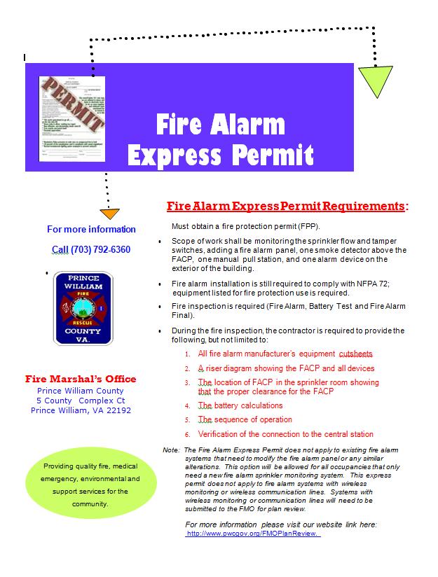
58 Page 58
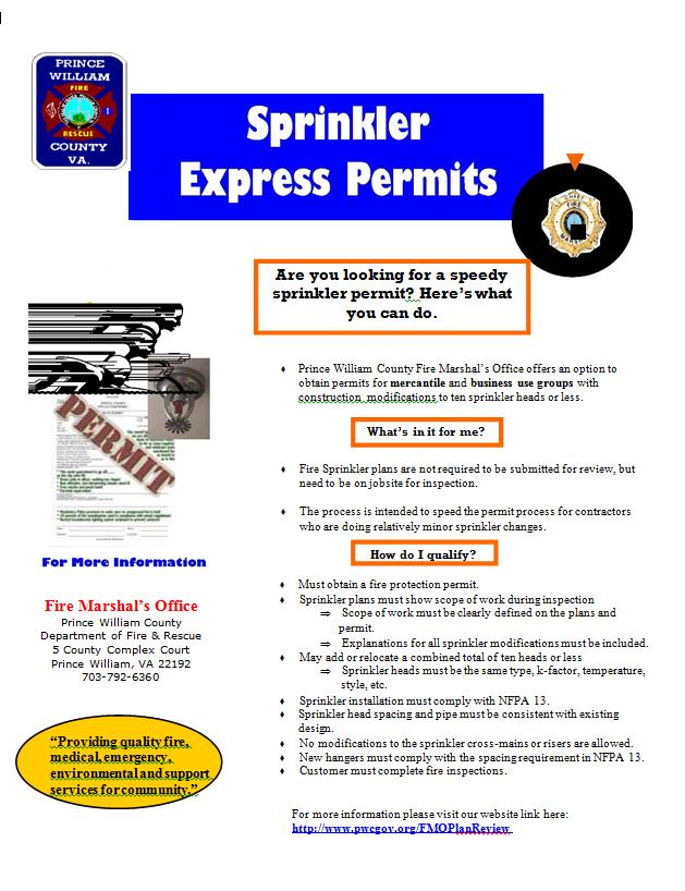
59 Page 59


60 Page 60
Expectations (continued)
") Expectations (continued) The work is ready to be inspected. If a problem develops where the work is not ready for inspection, call the FMO and cancel the inspection as soon as you are aware there is a
Expectations (continued) The work is ready to be inspected. If a problem develops where the work is not ready for inspection, call the FMO and cancel the inspection as soon as you are aware there is a
FMO Fire and Building
 FMO Fire and Building Inspection Reference Manual 2003 Code Edition, version 7.11.07 Prince William County Fire Marshal s Office 5 County Complex Court, Suite 160 Prince William, Virginia 22192 703-792-6360
New Construction Fire Inspection Process
 New Construction Fire Inspection Process This document is intended to provide the Owner, Designer, and/or Contractor of new construction with an outline of required fire inspections and with the specific
International Fire Code 2006 Requirements for Construction Plan Reviews of Commercial and Multi-Family Structures
 International Fire Code 2006 Requirements for Construction Plan Reviews of Commercial and Multi-Family Structures Please note this is not an all-inclusive list. The type and complexity of your project
EL DORADO COUNTY REGIONAL FIRE PROTECTION STANDARD
 EL DORADO COUNTY REGIONAL FIRE PROTECTION STANDARD INSTALLATION OF COMMERCIAL FIRE SPRINKLER SYSTEMS STANDARD #C-001 EFFECTIVE 03-25-2009 PURPOSE: To ensure that sprinkler plans submitted for review contain
Fire Protection Systems Plan Review
 Fire Protection Systems Plan Review and Inspections Prince William County Fire Marshal s Office December 15, 2005 Fire Marshal s Office Organizational Chart Kevin McGee Assistant Chief- Fire Marshal Warren
FIRE SPRINKLER SYSTEMS POLICY
 FIRE SPRINKLER SYSTEMS POLICY Revised 1/1/17 DESIGN AND SUBMITTAL REQUIREMENTS All new and existing fire sprinkler systems within the jurisdiction of the City Fire Department shall meet all of the applicable
CITY OF PASADENA FIRE DEPARTMENT
 Page 1 of 8 CITY OF PASADENA FIRE DEPARTMENT INSTALLATION OF COMMERCIAL SPRINKLERS (Revised 12/10/2014) SCOPE: This standard applies to the design and installation of automatic fire sprinkler systems in
Burnsville Fire Department 100 Civic Center Pky, Burnsville, MN Fire Marshal: FAX:
 Burnsville Fire Department 100 Civic Center Pky, Burnsville, MN 55337 Fire Marshal: 952-895-4579 FAX: 952-895-4512 2018 FIRE SUPPRESSION PERMIT APPLICATION PERMIT Wet System Dry System Cooking Hood Clean
Fire Sprinkler Plan Submittal Form
 Contents Fire Sprinkler Plan Submittal Form... 2 Standpipe Plan Review Submittals... 4 Fire Pump Plan Submittal Requirements... 6 Fire Alarm Plan Submittal Form... 8 Kitchen Hood Wet Chemical Submittal...10
MINOOKA FIRE PROTECTION DISTRICT Fire Prevention Bureau Fire Inspector Rodney Bradberry
 MINOOKA FIRE PROTECTION DISTRICT Fire Prevention Bureau Fire Inspector Rodney Bradberry Fire Alarm Systems Plan Review Checklist Date: Permit Number: Business Name: Address: Fire Alarm System Submittal
FIRE SPRINKLER SYSTEMS POLICY
 FIRE SPRINKLER SYSTEMS POLICY VERSION 1.012/2015 FIRE SPRINKLER SYSTEMS Design and Submittal requirements All new and existing fire sprinkler systems within the jurisdiction of the City of San Mateo Fire
AUTOMATIC FIRE SPRINKLER SYSTEM STANDARDS Development Standard #4.1 (Commercial Installations)
") AUTOMATIC FIRE SPRINKLER SYSTEM STANDARDS Development Standard #4.1 (Commercial Installations) This standard applies to the design and installation of automatic fire sprinkler systems in conjunction with
AUTOMATIC FIRE SPRINKLER SYSTEM STANDARDS Development Standard #4.1 (Commercial Installations) This standard applies to the design and installation of automatic fire sprinkler systems in conjunction with
AUTOMATIC FIRE SPRINKLER SYSTEMS
 MCKINNEY FIRE DEPARTMENT FIRE MARSHAL S OFFICE AUTOMATIC FIRE SPRINKLER SYSTEMS These guidelines are to be followed when a business, facility or organization installs an automatic fire sprinkler system
Fire Sprinkler Submittal Requirements and Acceptance Testing
 Lubbock Fire Marshal s Office 1601 Mac Davis Lane Lubbock, Texas 79401 806-775-2646 Fax 806-775-3508 fireprevention@mylubbock.us Fire Sprinkler Submittal Requirements and Acceptance Testing To all Registered
CLARK COUNTY FIRE DEPARTMENT Fire Prevention Bureau
 CLARK COUNTY FIRE DEPARTMENT Fire Prevention Bureau 575 E. Flamingo Road, Las Vegas, NV 89119 (702) 455-7316 FAX (702) 455-7347 Permit Type: 105.7.13 Control Number: A.0 Effective Date: 11/15/11 TITLE:
GLENDALE FIRE DEPARTMENT FIRE MARSHAL S OFFICE
 GLENDALE FIRE DEPARTMENT FIRE MARSHAL S OFFICE To: Contractors From: Charles Jenkins, Fire Marshal Subject: Contractor s Guide This guide is provided by the Fire Marshal as a service to the construction
A. Hydraulic calculations shall be prepared in accordance with Chapter 23 of NFPA 13 with the following exceptions:
 SECTION 21 13 13 WET-PIPE FIRE SPRINKLER SYSTEM PART 1 - GENERAL 1.1 RELATED DOCUMENTS: A. The Conditions of the Contract and applicable requirements of Division 1, "General Requirements", and Section
Montgomery County Government Building and Codes Department 350 Pageant Lane, Suite 309 Clarksville, TN 37040
 Montgomery County Government Building and Codes Department 350 Pageant Lane, Suite 309 Clarksville, TN 37040 SPRINKLER SHOP DRAWINGS 2007 NFPA 13 and 2007 NFPA 24 Project: Listed items require sprinkler
APPENDIX H (DESIGN SUBMISSION CRITERIA)
") APPENDIX H (DESIGN SUBMISSION CRITERIA) FIRE ALARM SYSTEM As per ACCORD standard Part 5, section 5.7 Fire Alarm System Design to be verified by ACCORD Chief Safety Inspector. Testing of the installation
APPENDIX H (DESIGN SUBMISSION CRITERIA) FIRE ALARM SYSTEM As per ACCORD standard Part 5, section 5.7 Fire Alarm System Design to be verified by ACCORD Chief Safety Inspector. Testing of the installation
GLENDALE FIRE DEPARTMENT FIRE MARSHAL S OFFICE
 GLENDALE FIRE DEPARTMENT FIRE MARSHAL S OFFICE To: From: Subject: Whom It May Concern Carl Ray Austerman, Fire Marshal Contractor s Guide Welcome to the Glendale Fire Department s Contractors Guide. This
PLAN REVIEW CHECKLIST
 PLAN REVIEW CHECKLIST Date Documents Submitted: Log No.: File No.: Property Information Building Name: Building Address: Owner s Name: Owner s Address: Owner s Phone: Fax: E-mail: System Designer/Contractor
Division 21: FIRE SUPRESSION WET-PIPE SPRINKLER PROTECTION SYSTEM. The Academy Sept Table of Contents 1 Division 21
 Division 21: FIRE SUPRESSION 21 1313 WET-PIPE SPRINKLER PROTECTION SYSTEM Table of Contents 1 Division 21 SECTION 21 1313 WET-PIPE SPRINKLER PROTECTION SYSTEM PART 1 - GENERAL 1.1 RELATED DOCUMENTS A.
EL DORADO COUNTY REGIONAL FIRE PROTECTION STANDARD
 EL DORADO COUNTY REGIONAL FIRE PROTECTION STANDARD Installation of Residential Fire Sprinkler Systems STANDARD #C-002 EFFECTIVE 03-19-2009 PURPOSE: To ensure that sprinkler plans submitted for review contain
Port of St Helens SIA Aircraft Hanger Scappoose, OR
 Port of St Helens SIA Aircraft Hanger Scappoose, OR AUTOMATIC FIRE SPRINKLER SYSTEM REVISION 2 MARCH 12, 2018 Scope: Furnish and install foam and water fire protection system including underground entrance
Design & Construction Standards, Revised January
 PART 1 GENERAL 1.01 Scope of Standard A. This standard provides general requirements of The University of Texas at Austin for the design and construction of standpipe systems to include combination standpipe
SECTION WET-PIPE SPRINKLER SYSTEMS
 SECTION 21 13 13 WET-PIPE SPRINKLER SYSTEMS PART 1 - GENERAL 1.1 SCOPE OF WORK A. Design, installation and testing shall be in accordance with NFPA 13 except for specified exceptions. B. The demolition
PART II: New Construction Inspections and Acceptance Testing Procedures
 Stafford County Fire Marshal s Office Handbook for Building/Fire Code Policies and Guidelines PART II: New Construction Inspections and Acceptance Testing Procedures Phone: 540-658-8648 Fax: 540-658-9128
CubeSmart Gulf Breeze Storage AUTOMATIC FIRE SPRINKLER SYSTEM
 SECTION 21 0000 AUTOMATIC FIRE SPRINKLER SYSTEM PART 1 GENERAL 1.1 QUALITY ASSURANCE A. Codes and Standards: 1. FBC (Florida Building Code 2015) 2. FBC (Florida Fire Code 2015) 3. NFPA #13R (Standard for
STATE FIRE MARSHAL S REQUIRED FIRE PROTECTION SYSTEMS NARRATIVE REPORT
 STATE FIRE MARSHAL S REQUIRED FIRE PROTECTION SYSTEMS NARRATIVE REPORT The interaction of fire protection systems can be extremely complex. The detection of a fire in a building by an automatic device
HIGH-RISE RETROFIT ORDINANCES - NO and NO
 INFORMATION BULLETIN / PUBLIC - BUILDING CODE REFERENCE NO.: LAMC 91.8604 Effective: 9-06-90 DOCUMENT NO. P/BC 2002-054 Revised: 4-15-03 Previously Issued As: MGD 88 HIGH-RISE RETROFIT ORDINANCES - NO.
Module 3. Water-Based Suppression Systems (WBSS) Part II: Highlights of Code Requirements
 Part II: Highlights of Code Requirements") Module 3 Water-Based Suppression Systems (WBSS) Part II: Highlights of Code Requirements 1 WATER-BASED SUPPRESSION SYSTEMS-PART TWO This module covers: 1. Ohio Building Code requirements and when and why
Module 3 Water-Based Suppression Systems (WBSS) Part II: Highlights of Code Requirements 1 WATER-BASED SUPPRESSION SYSTEMS-PART TWO This module covers: 1. Ohio Building Code requirements and when and why
University of Houston Master Construction Specifications Insert Project Name SECTION DRY-PIPE FIRE SPRINKLER SYSTEM PART 1 - GENERAL
 SECTION 21 13 16 DRY-PIPE FIRE SPRINKLER SYSTEM PART 1 - GENERAL 1.1 RELATED DOCUMENTS: A. The Conditions of the Contract and applicable requirements of Division 1, "General Requirements", and Section
Rancho Cucamonga Fire Protection District Prevention Bureau Standard
 Rancho Cucamonga Fire Protection District Prevention Bureau Standard Title: Fire Alarm and Monitoring Systems Standard # 9-3 Effective: May 2002 Number of Pages: 7 Updated: December 2016 for consistency
D. The work addressed in this section consists of a fire protection system, which may include coordination with one or more of the following:
 PART 1 GENERAL 1.01 Scope of Standard A. This standard provides general requirements of Sam Houston State University for the design and construction of standpipe systems to include combination standpipe
Sprinkler Permit Applications
 REQUIREMENTS FOR NFPA 13 SYSTEM Building Inspections Sprinkler Permit Applications A complete application for a Sprinkler Permit will comply with the requirements of Chapter 8 of NFPA 13. Hydraulic calculations
Narrative Reports As Regulated by 780 CMR, Section 903.0
 EXHIBIT 20 Narrative Reports As Regulated by 780 CMR, Section 903.0 903.1.1 - FIRE PROTECTION CONSTRUCTION DOCUMENTS a. Basis (methodology) of design for the protection of the occupancy and hazard for
C. All components of the systems described shall meet the requirements as stated herein and shall be approved by the Architect and Consultant.
 SECTION 218800 - FIRE PROTECTION 1. GENERAL A. Provisions of Division 1, GENERAL REQUIREMENTS, and Section 230000, MECHANICAL GENERAL CONDITIONS, and Section 230050, SEISMIC PROTECTION are a part of this
CITY OF MADISON FIRE DEPARTMENT (MFD) FIRE PROTECTION SYSTEM PLANS
 FIRE PROTECTION SYSTEM PLANS") CITY OF MADISON FIRE DEPARTMENT (MFD) FIRE PROTECTION SYSTEM PLANS Fire Protection Systems includes the following: Alternate Fire Suppression Systems Atrium Fire Protection Systems Automatic Fire Sprinkler
CITY OF MADISON FIRE DEPARTMENT (MFD) FIRE PROTECTION SYSTEM PLANS Fire Protection Systems includes the following: Alternate Fire Suppression Systems Atrium Fire Protection Systems Automatic Fire Sprinkler
COBB COUNTY SCHOOLS /S&A % BID DOCUMENTS 2/18/11 SECTION SPRINKLER SYSTEM
 SECTION 21 10 00 PART 1 - GENERAL 1.1 CODES A. Work shall conform to NFPA 13 Sprinkler Systems, 2002 Edition and NFPA 24 Outside Protection, 2002 Edition. NFPA 14 Standpipe Systems, 2000 Edition and International
Moreno Valley Fire Department Fire Prevention Bureau. New and Existing Fire Alarm & Signaling Systems Guideline
 Moreno Valley Fire Department Guideline Approved and Authorized By: Adria Reinertson, Fire Marshal Issued: May 8, 2017 Alarm & Signaling Systems PURPOSE Fire alarm and signaling systems are designed to
SANTA CLARA COUNTY Winchester Blvd., Los Gatos, CA (408) (408) (fax)
 (408) (fax)") FIRE DEPARTMENT SANTA CLARA COUNTY 14700 Winchester Blvd., Los Gatos, CA. 95032-1818 (408) 378-4010 (408) 378-9342 (fax) www.sccfd.org STANDARD DETAILS & SPECIFICATIONS Spec No C-4 Rev. Date 03/10/10 SUBJECT:
FIRE DEPARTMENT SANTA CLARA COUNTY 14700 Winchester Blvd., Los Gatos, CA. 95032-1818 (408) 378-4010 (408) 378-9342 (fax) www.sccfd.org STANDARD DETAILS & SPECIFICATIONS Spec No C-4 Rev. Date 03/10/10 SUBJECT:
FIRE CODE. Coal City Fire District International Fire Code Update. 35 S. DeWitt Place Coal City, IL
 . 2015 FIRE CODE 2015 International Fire Code Update Coal City Fire District 35 S. DeWitt Place Coal City, IL 60416 815-634-4700 Table of Contents SECTION 109 VIOLATIONS... 3 SECTION 111 STOP WORK ORDER...
DIVISION 21 - FIRE SUPPRESSION
 DIVISION 21 - FIRE SUPPRESSION DESIGN CRITERIA It is the policy of UC Davis to install fire sprinkler systems in all new construction/facilities. If the building is classified as a pole barn, shed, carport,
CHAPTER 61G15-32 RESPONSIBILITY RULES OF PROFESSIONAL ENGINEERS CONCERNING THE DESIGN OF FIRE PROTECTION SYSTEMS
 CHAPTER 61G15-32 RESPONSIBILITY RULES OF PROFESSIONAL ENGINEERS CONCERNING THE DESIGN OF FIRE PROTECTION SYSTEMS 61G15-32.001 61G15-32.002 61G15-32.003 61G15-32.004 61G15-32.005 61G15-32.006 61G15-32.007
PLAN REVIEW SUBMITTAL GUIDE
 PLAN REVIEW SUBMITTAL GUIDE Plans, specifications and other construction documentation for the initial plan review should be as complete as possible at the time of submittal. Use this convenient guide
FIRE PROTECTION. 1. Vertical fire pumps shall not be used at the University.
 15500 - FIRE PROTECTION PART I DESIGN GUIDELINES A. General 1. Vertical fire pumps shall not be used at the University. 2. coupling piping shall be permitted for sprinkler and standpipe systems only. B.
To expedite the plan review and inspection processes, please refer to the information below.
 Guidelines: The goal of the Denison Fire Department is to assist its customers in understanding our submittal, plan review and inspection process and policies, as they pertain to new construction. Familiarity
Construction and Development Guide
 Construction and Development Guide **Based on the 2014 Indiana Fire Prevention Code and relevant NFPA Codes and Standards ** Copyright 2018 Clay Fire CRRD 1 P a g e Table of Contents Map of Jurisdiction...
SECTION WATER BASED FIRE SUPPRESSION SYSTEMS
 PART 1: GENERAL 1.01 Scope of Standard A. This standard provides general guidance concerning the specific preferences of Texas State University-San Marcos for automatic fire sprinkler and standpipe systems.
SECTION (13900) - FIRE SUPPRESSION SYSTEMS
 - FIRE SUPPRESSION SYSTEMS") PART 1 GENERAL 1.01 SUMMARY SECTION 21 10 00 (13900) - FIRE SUPPRESSION SYSTEMS A. Section Includes: 1. Pipe and Fittings. 2. Sprinklers. B. Related Documents: 1. Marriott s Fire Protection and Life Safety
PART 1 GENERAL 1.01 SUMMARY SECTION 21 10 00 (13900) - FIRE SUPPRESSION SYSTEMS A. Section Includes: 1. Pipe and Fittings. 2. Sprinklers. B. Related Documents: 1. Marriott s Fire Protection and Life Safety
FIRE ALARM APPLICATION CITY OF MADISON HEIGHTS
 FIRE ALARM APPLICATION CITY OF MADISON HEIGHTS www.madison-heights.org COMMUNITY DEVELOPMENT DEPARTMENT BUILDING DIVISION 300 W. THIRTEEN MILE RD. MADISON HEIGHTS, MICHIGAN 48071 (248) 583-0831 FAX (248)
Western Michigan University Facilities Management Engineering Division
 Western Michigan University Facilities Management Engineering Division Design Guidelines for Facilities Construction: DESIGN GUIDELINE DG21-1 Fire Suppression Systems & Equipment I. GENERAL... 1 A. General
1.1 Refer to Section for General Mechanical Requirements. 1.3 Refer to Section for Pipe and Equipment Identification Requirements.
 FIRE PROTECTION GENERAL INFORMATION 1.1 Refer to Section 230000 for General Mechanical Requirements. 1.2 Refer to Section 230529 for Hangers and Supports. 1.3 Refer to Section 230553 for Pipe and Equipment
SACRAMENTO FIRE DEPARTMENT FIRE PREVENTION DIVISION FIRE DEPARTMENT DEVELOPMENT SERVICES UNIT CONTRATOR INFORMATION PACKET
 SACRAMENTO FIRE DEPARTMENT FIRE PREVENTION DIVISION FIRE DEPARTMENT DEVELOPMENT SERVICES UNIT CONTRATOR INFORMATION PACKET 1 SACRAMENTO FIRE DEPARTMENT FIRE PREVENTION DIVISION FIRE DEPARTMENT DEVELOPMENT
DIVISION 21 FIRE SUPPRESSION FIRE SUPRESSION
 DIVISION 21 FIRE SUPPRESSION 21 00 00 FIRE SUPRESSION 21 01 00 Operation and Maintenance of Fire Suppression 21 01 10 Operation and Maintenance of Water Based Fire Suppression Systems 21 01 20 Operation
B. Product Data: Provide manufacturers catalogue information. Indicate valve data and ratings.
 DIVISION 21 21 05 00 COMMON WORK RESULTS FOR FIRE SUPPRESSION PART 1 GENERAL 1.1 SECTION INCLUDES A. Pipe, fittings, sleeves, escutcheons, seals, and connections for sprinkler systems. 1.2 RELATED REQUIREMENTS
Commercial Remodel/ Add On Rules and Regulations
 Commercial Remodel/ Add On Rules and Regulations Public Works and Community Development Department City of Shenandoah 29955 I-45 North Shenandoah, Texas 77381 281-298-5522 www.shenandoahtx.us Construction
2. Welding Materials and Procedures shall conform to the ASME Code.
 PART 1 GENERAL 1.01 Scope of Standard A. The design guidelines contained herein include the requirements for systems, materials, fittings and valves utilized for fire protection systems at Sam Houston
MONTECITO FIRE PROTECTION DISTRICT
 Section 5a MONTECITO FIRE PROTECTION DISTRICT FIRE PROTECTION PLAN Residential Automatic Fire Sprinkler System Installations I Automatic Fire Sprinkler System Standards 1. Definition and Standard: An automatic
FIRE SPRINKLER SHOP DRAWING SUBMITTAL REQUIREMENTS
 Department of Fire Rescue & Emergency Services Fire Marshal s Office Dania Beach District 103 West Dania Beach Blvd. Dania Beach, Florida 33004 Office: (954)342-4262 Fax: (954)342-4265 FIRE SPRINKLER SHOP
SECTION : FIRE PROTECTION SYSTEMS
 SECTION 21 00 10: FIRE PROTECTION SYSTEMS 1. GENERAL A. This section applies to the design and performance information for fire protection and suppression systems. B. All fire protection materials and
Bold items are particular to the City of Euless
 EULESS FIRE DEPARTMENT FIRE MARSHAL S OFFICE INFORMATION LINE: Revised 8/2004 Fire Chief Lee Koontz Fire Marshal Paul Smith EFD-FMO 3-1 2003 International Fire & Building Code as Amended NFPA Standards
FIRE INSPECTION CHECKLIST
 Applicable Base Codes FIRE INSPECTION CHECKLIST Florida Fire Prevention Code, 5th Edition NFPA 1, Uniform Fire Code, Florida 2012 Edition NFPA 101, Life Safety Code, Florida 2012 Edition NFPA 13, 2010
FIRE & LIFE SAFTEY STANDARD
 Title: Effective Date: 01/01/14 Revised Date: 1/1/14 Code References: Title 16, Chapter 16.16 of the Roseville Municipal Code, NFPA 72 Note: This standard is a summary of Fire Department clarifications
DIVISION 21 - FIRE SUPPRESSION
 DIVISION 21 - FIRE SUPPRESSION DESIGN CRITERIA It is the policy of UC Davis to install fire sprinkler systems in all new construction/facilities. If the building is classified as a pole barn, shed, carport,
UNIVERSITY OF MISSOURI Fire Protection System Design 2016 Q1
 GENERAL: 1. All fire protection systems shall be installed in accordance with the International Fire Code and applicable NFPA standards. This guideline provides additional requirements for the design and
Requirements for the protection of High-Piled Combustible Storage (HPCS) Effective Date: January 2011
 Effective Date: January 2011") 1.0 GENERAL: Requirements for the protection of High-Piled Combustible Storage (HPCS) Effective Date: January 2011 1.1 PURPOSE -The intent of this guideline is to provide the requirements for the protection
1.0 GENERAL: Requirements for the protection of High-Piled Combustible Storage (HPCS) Effective Date: January 2011 1.1 PURPOSE -The intent of this guideline is to provide the requirements for the protection
Fire Permit Application
 Fire Permit Application FOR STAFF USE ONLY Case Permit Number: Plan Number: Related permits: Project #: Responsibility for information Although designated Department staff members will help you with general
WALL ESCUTCHEON PIPE SEAL WITH APPROVED FIRE CAULKING (SEE SPECIFICATIONS) NOTE: 12" 12" 24"
 NOTE: 12 12 24") SOUTH TEJON ST., SUITE 00 COLORADO SPRINGS, CO. 00 TELE.: FAX: WALL ESCUTCHEON PACK ANNULAR SPACE WITH MINERAL WOOL GENERAL NOTES. THIS PROJECT INCLUDES THE DESIGN AND PROVISION OF A NEW WET SPRINKLER
SOUTH TEJON ST., SUITE 00 COLORADO SPRINGS, CO. 00 TELE.: FAX: WALL ESCUTCHEON PACK ANNULAR SPACE WITH MINERAL WOOL GENERAL NOTES. THIS PROJECT INCLUDES THE DESIGN AND PROVISION OF A NEW WET SPRINKLER
Contren Learning Series Apprenticeship Training Program for Fire Sprinkler Fitters
 Contren Learning Series Apprenticeship Training Program for Fire Sprinkler Fitters (Published jointly by American Fire Sprinkler Association and the National Center for Construction Education and Research.)
Fire & Life Safety Supplemental Rules & Regulations for New Construction & Significant Remodels
 DEPARTMENT OF PUBLIC SAFETY FIRE MARSHAL S OFFICE 9611 SE 36 TH ST Mercer Island, WA 98040 (206) 236-3515 direct; (206) 236-3622 FAX Rod Mandery, Fire Marshal Updated version: 03-19-2002 Fire & Life Safety
2. The Group F occupancy has have an a combined occupant load of 500 or more above or below the lowest level of exit discharge.
 2. The Group F occupancy has have an a combined occupant load of 500 or more above or below the lowest level of exit discharge. Exception: Manual fire alarm boxes are not required where the building is
WEST VIRGINIA UNIVERSITY
 WEST VIRGINIA UNIVERSITY Environmental Health and Safety (SOP) WV State Fire Marshal (SFM) Project Plans Review Process & Procedures West Virginia University Environmental Health & Safety Page 1 of 10
September 30, Dear Fire Suppression System Contractor/Designer:
 CITY OF BOZEMAN FIRE DEPARTMENT P.O. Box 1230 Bozeman, Montana 59771-1230 Phone (406) 582-2350 CITY OF BOZEMAN BUILDING DEPARTMENT 20 E Olive St, STE 208 Bozeman, Montana 59715-4790 Phone (406) 582-2375
RESIDENTIAL FIRE SPRINKLER SYSTEMS POLICY
 RESIDENTIAL FIRE SPRINKLER SYSTEMS POLICY Plan Submittal and Inspection Requirements Revised 01/18/18 All residential fire sprinkler systems within the jurisdiction of the Fire Department shall meet all
SECTION WET PIPE FIRE PROTECTION SPRINKLER SYSTEM
 SECTION 213100 WET PIPE FIRE PROTECTION SPRINKLER SYSTEM PART 1 - GENERAL 1.01 GENERAL REQUIREMENTS A. The requirements of the General Conditions and Supplementary Conditions apply to all work herein.
FIRE SUPPRESSION SPRINKLER SYSTEM
 PART 1 GENERAL 1.01 DESCRIPTION A. The provisions of the General Requirements, Supplementary Requirements, and Division 1 apply to the plumbing work specified in this Division. B. The requirements of this
FIRE PREVENTION OFFICE Placer Hills Fire Protection District NEW PROJECT GUIDELINES
 Established 1949 FIRE PREVENTION OFFICE Placer Hills Fire Protection District NEW PROJECT GUIDELINES The following are guidelines for new development. Any submitted plans must comply with these guidelines,
Fire Sprinkler System Design and Installation Requirements
 Fire Sprinkler System Design and Installation Requirements The Park City Fire Service District (PCFD) and Park City Municipal Corporation (PCMC) have made the following amendments to the State of Utah
City of Vista Fire Department
 City of Vista Fire Department Development Services Section 600 Eucalyptus Avenue, Vista CA 92084 Guideline: Underground Piping for Private Fire Hydrants & Fire Sprinkler Supply. Updated: January, 2008
SECTION : FIRE ALARM & DETECTION SYSTEMS
 SECTION 28 31 10: FIRE ALARM & DETECTION SYSTEMS 1. GENERAL A. This section applies to fire detection/alarm system and carbon monoxide system components and equipment installed during new construction
Oxnard Fire Department 360 W. Second Street Oxnard, CA (805) Fax (805)
 Fax (805)") Oxnard Fire Department 360 W. Second Street Oxnard, CA 93030 (805) 385-7722 Fax (805) 385-8009 FIVE YEAR CERTIFICATION REPORT Service and maintenance report for automatic fire extinguishing systems, including
Oxnard Fire Department 360 W. Second Street Oxnard, CA 93030 (805) 385-7722 Fax (805) 385-8009 FIVE YEAR CERTIFICATION REPORT Service and maintenance report for automatic fire extinguishing systems, including
SECTION FIRE-SUPPRESSION STANDPIPES
 PART 1 - GENERAL 1.1 DESCRIPTION Fire-suppression wet and manual dry standpipes. 1.2 SCOPE OF WORK SECTION 21 12 00 A. Design, installation and testing shall be in accordance with NFPA 14 except for specified
SECTION WET-PIPE SPRINKLER SYSTEMS
 SECTION 21 13 13 PART 1 - GENERAL 1.1 SCOPE OF WORK A. Design, installation and testing shall be in accordance with NFPA 13 except for specified exceptions. B. The design and installation of a hydraulically
Commercial Rules and Regulations
 Commercial Rules and Regulations Public Works and Community Development Department City of Shenandoah 29955 I 45 North Shenandoah, Texas 77381 281 298 5522 www.shenandoahtx.us Construction Documents Submit
FIRE SERVICE FEATURES
 CHAPTER 5 FIRE SERVICE FEATURES SECTION 501 GENERAL 501.1 Scope. Fire service features for buildings, structures and premises shall comply with this chapter. 501.2 Permits. A permit shall be required as
SANTA ROSA FIRE DEPARTMENT FIRE PREVENTION BUREAU PLAN REVIEW CHECKLIST
 July 1, 2010 SANTA ROSA FIRE DEPARTMENT FIRE PREVENTION BUREAU PLAN REVIEW CHECKLIST TENANT IMPROVEMENTS Address: Permit #: Inspector: Date: Status: Inspector: Date: Status: A-Approved; AC-Approved w/comments;
Rocky Mountain Fire Protection District 4390 Eldorado Springs Drive Boulder, CO
 Rocky Mountain Fire Protection District 4390 Eldorado Springs Drive Boulder, CO 80303 303-494-3735 Contractor s Checklist and Installation Guide TABLE OF CONTENTS Fire Protection Narrative........... 3
Fire Prevention Coffee Break Training. February 2017
 Fire Prevention Coffee Break Training February 2017 Agenda FDC s - Lund Standpipes - Phelan Fire Alarm Testing Phelan/Dooley Questions and Answers Open Forum Standpipe requirement Standpipes are required
DIVISION 21 FIRE SUPPRESSION
 Table of Contents 21 00 00 FIRE SUPPRESSION...2 A. REFERENCE ABBREVIATIONS... 2 B. GENERAL... 2 C. DESIGN REQUIREMENTS... 2 D. DOCUMENTATION... 2 21 08 00 FIRE SUPPRESSION COMMISSIONING...2 A. PIPE CLEANING...
A. This section includes design and performance information for fire protection and suppression systems.
 SECTION 21 00 10: FIRE PROTECTION SYSTEM DESIGN 1. SUMMARY A. This section includes design and performance information for fire protection and suppression systems. 2. GENERAL A. All fire protection materials
Second Revision No. 20-NFPA [ Section No. 1.4 ] Supplemental Information. Submitter Information Verification. Committee Statement
![Second Revision No. 20-NFPA [ Section No. 1.4 ] Supplemental Information. Submitter Information Verification. Committee Statement](/thumbs/79/80346596.jpg "Second Revision No. 20-NFPA [ Section No. 1.4 ] Supplemental Information. Submitter Information Verification. Committee Statement") Second Revision No. 20-NFPA 14-2015 [ Section No. 1.4 ] 1.4* Equivalency. Nothing in this standard is intended to prevent the use of systems, methods, or devices of equivalent or superior quality, strength,
Second Revision No. 20-NFPA 14-2015 [ Section No. 1.4 ] 1.4* Equivalency. Nothing in this standard is intended to prevent the use of systems, methods, or devices of equivalent or superior quality, strength,
Minimum Standards for Engineers Practicing Fire Protection Engineering in the State of Oklahoma September 14, 2016
 1. Introduction The intent of this document is to establish minimum standards for the practice of fire protection engineering within the State of Oklahoma as conducted by licensed professional engineers.
OCFA Planning and Development Section Fees Effective September 28, 2015
 Description (IFP) PLANNING & SITE DEVELOPMENT PR0 PR4 PR5 California Environmental Quality Act (CEQA), Environmental Impact Report (EIR), Notice of Preparation (NOP), Advance Planning requests for information
Design & Construction Standards, Revised January
 PART 1 GENERAL 1.01 Scope of Standard A. This standard provides general requirements of The University of Texas at Austin for fire-extinguishing systems other than water-based fire suppression systems.
DESIGN AND CONSTRUCTION STANDARDS SPECIFICATION GUIDELINES
 SECTION 21 13 00 - FIRE SUPRESSION SPRINKLER SYSTEMS SCOPE OF WORK This standard provides general guidance concerning the specific preferences of The University of South Alabama for automatic fire sprinkler
FIVE YEAR AUTOMATIC FIRE EXTINGUISHING SYSTEMS CERTIFICATION REPORT
 SANTA MONICA FIRE DEPARTMENT Fire Prevention Division 333 Olympic Drive 2 nd Floor Santa Monica, CA 90401 310-458-8915 / Fax 310-395-3395 FIVE YEAR AUTOMATIC FIRE EXTINGUISHING SYSTEMS CERTIFICATION REPORT
SANTA ROSA FIRE DEPARTMENT FIRE PREVENTION BUREAU STANDARD
 July 1, 2010 SANTA ROSA FIRE DEPARTMENT FIRE PREVENTION BUREAU STANDARD STANDPIPE SYSTEMS PURPOSE This standard outlines the general requirements for the installation of standpipe systems. CODE REFERENCES
Winnipeg Fire Department Fire Prevention Branch
 Winnipeg Fire Department Fire Prevention Branch Manitoba Fire Code Life-Safety Equipment Maintenance Requirements The Fire Prevention Branch of the Winnipeg Fire Department has prepared this document of