MultiZone Gas Monitors
|
|
|
- Alexina Ferguson
- 5 years ago
- Views:
Transcription

")


1 MultiZone Gas Monitors HGM-MZ AGM-MZ CO 2 -MZ (Halogen) (Ammonia) (Carbon Dioxide) Instruction Installation / Operation / Maintenance Rev. 9 December 2011 UL CAN/CSA 22.2 No EN 14624
2 WARRANTY s ap. Bacharach Bacharach ture and shown to Bacharach Inc. that - B S includ tion incidental or consequen Register your warranty by visiting n in conn Patent ut the prior written ii P/N:
3 Table of Contents SECTION 1. INTRODUCTION SECTION 2. INSTALLATION Installation Considerations Inspection Moun Operation P/N: iii
4 Optional Connection SECTION 3. SETUP PROGRAMMING Initial Power Up Setup Screen Location Loop Mode Zero Mode Node Address Password Node Address Password Sensor Baseline SECTION 4. GENERAL OPERATION w Location P/N:
5 CO Gases stic Screen SECTION 5. MAINTENANCE APPENDIX A. RECOMMENDED REFRIGERANT GAS ALARM SETTINGS APPENDIX B. RS-485 COMMUNICATIONS PROTOCOL B B B B B B B B.3.5. s B B B B B and A B B B B B P/N:
6 B B B B B B B B MO B APPENDIX C. SYSTEM MENU MAP APPENDIX D. AGENCY APPROVALS APPENDIX E. SERVICE CENTERS INDEX P/N:
7 SECTION 1. INTRODUCTION 1.1. About This Manual Bacharach Multi-Zone Gas Monitor. and the proper please read l. It s, operation, Warnings and Cautions al or as labeled on the gas monitor. WARNING: WARNING indicates a potential WARNING: e word WARNING indicates a potential electrical shock. It calls attention to a procedure, practice, condition, or the CAUTION: CAUTION IMPORTANT: IMPORTANT to the e Safety Precautions Hazardous Areas WARNING: not DO NOT locations. P/N:
8 Combustible and Flammable Gases WARNING: As such, it is the AC Power Supply IMPORTANT: e AC power source,. WARNING: installation Protective Grounding WARNING: Explosive Atmosphere WARNING: or aerosols a Proper Exhaust Venting WARNING: Accessing the Interior of the Monitor WARNING: ower. 2 P/N:
9 Misuse and Modifications to the Instrument WARNING: th NOTE: In Case of Malfunction Fusing WARNING: - and. WARNING: Installation Category IMPORTANT: Altitude Limit IMPORTANT: Cleaning NOTE: and/or P/N:


10 1.4. Key External Hardware Components Screen Solenoid Connections LED Indicators Monitor is powered on Figure 1-1. Multi-Zone Monitor Front View NOTE: inside the Multi-. Standard Accessories for a 4-Point System QTY Description Part Number 5 Line End Multi-Zone Instruction Manual Functional Overview General Description Gas.. Bacharach Multi-Zone Monitor pr.. and indicators conditions contacts 4 P/N:
11 lea. with and optional two-channel the. A indicator, codes caus Communications Options is the protocol standard C port.. B protocols Understanding Monitoring Levels set points s. M and needless s AE A. tor. le. ints Response to the Presence of Multiple Refrigerants (HGM Only) Suggested Location of Sampling Points.,. collection point. unit will rea air. r and tend. hat collected. sources. set points DO NOT block any of the zones.. MZ. should not t. s. haust line should run to an outside location. P/N:
 Module, s Note that ther on, spill, conditions. Figure 1-2.")
12 NOTE: ne 500. test. s the optional water stop Locating a Remote Display (Optional) Module, s Note that ther on, spill, conditions. Figure 1-2. MZ/RD Gas Leak Monitor Placement in a Mechanical Room NOTE: which area P/N:
13 1.6. Specifications HGM-MZ Specifications Product Type Sensitivity Measuring Range Accuracy 1 Gas Library All All - - CFC: HFC: c HCFC: Halon: Other:, AGM-MZ Specifications Product Type Sensitivity Measuring Range Accuracy 1 Gas Library CO 2 -MZ Specifications Product Type Sensitivity Measuring Range Accuracy 1 Gas Library At C - P/N:
14 General Multi-Zone Specifications Coverage Detector Type Front Panel Size (H x W x D) Weight Sampling Mode Re-Zero Response Time System Noise Monitoring Distance Conditioned Signal Alarms Communications Power Safety Mode Operating Temp Ambient Humidity AC Power Certification Warranty Altitude Limit Sensor Life to 315 seconds Less than contacts rated 2A at Module - -. eters retained. - UL , CAN/CSA 22.2 No & C 7-8 P/N:
15 SECTION 2. INSTALLATION 2.1. Installation Considerations Warnings and Cautions WARNING: WARNING: the CAUTION: in the MZ enclosure the. CAUTION: Inspection. -.. Open the enclosure the. ce Center Location of the Monitor MZ is proportional to the... Installation. I NOTE: Mounting Instructions NOTE: P/N:
16 ¼ inch Allow the screw heads to protrude ¼ inch. Figure 2-1. MZ Monitor Mounting Specifications, Connecting Gas Sample Lines Overview MZ to.. All air, line connections are 10 P/N:
17 Figure 2-2. MZ Monitor Side View Tubing Considerations Use ¼ P/N , press the plasti, then to ensure Connecting Purge Line is that is into I A line-end lter P/N line when the. in 2 applications. IMPORTANT (CO 2 Only): Because CO 2 BE run 2 2 CO 2 Atmospheric Concentration Connecting Exhaust Line e that is es not require a line- can enter it Connecting Sample Intake Lines MZ.. Additional P/N:
18 P/N , and o is used. Otherwise, the,200. All line. A line-end P/N tached to the. Line- to cm to 45.7 cm) IMPORTANT:. the end- -line water stop can - -line water stop are supplied with a standard unit. NOTE: - or end- -line water stop, should section Suggested Location of Sampling Points Installing an Optional Splitter Kit Splitter its allow the MZ es Bacharach s and accessories to instruction the installation instruction Connecting the Water Trap is an optional that result in water or condensation Install the water trap cut where the us the into the and the used to secure the water trap in place. NOTE: line water stop IMPORTANT: A water trap 12 P/N:

19 2.3. Interior Components Figure 2-3. MZ Monitor Interior Components NOTE:. Ple or repair s 2.4. Electrical Wiring MZ 50/60 source ld listed 3-conductor wire rated 300 and install electrical conduit Locate the AC input t and round stud. neutral and LINE 2 -, washers wire input round stud and. WARNING: Electrical installation should codes. P/N:
20 WARNING: accordance with NEC/CEC and local codes. WARNING: wire stud. IMPORTANT: in the MZ enclosure. leads. the operator. -, l and neutral Figure 2-4. Multi-Zone AC Input Power and Ground Connections 14 P/N:

21 2.5. Connecting Communications Devices Remote Display Module (RD) Connection MZ is connected to the optional. st MZ and MZ and connector in the MZ see C. Note the wire color. 3.. Note the wire color. 4. point connector S see this topic in the. his connector is located on the. 6. un the wire to the and connect the twisted shielded pair -485 S MZ Integrating with Building Management Systems MZ. nnected to the -485 connector inside the MZ. is the standard protocol.. Locate the -485 connector Larger Integrated Systems MZ to a Buildi. In this MZ to the. in the Communications Connections section the to a B. Figure 2-5. RS-485 Connector P/N:

22 Changing Terminator Switch Settings switch. MZ. is connected as le IN. Locate switch #4. Note that switches 1-3 are use. Figure 2-6. Termination Switches Personal Computer MZ -232 in on the the enclosure. as a dow at. NOTE: P/N:

23 2.6. Terminating Multiple Monitors Figure 2-7. Termination Settings for a Network of Multiple Monitors and a Remote Display NOTE:, t position. NOTE:, t - cannot -strand shielded and twisted pair # Connecting to a Building Management System MZ B S -485 connector. address on each MZ 1 to 15 in order to. NOTE:. MZ it may not. he has two ports BMS. port while MZ s. to the MZ MZ/. P/N:


24 NOTE: setup. Figure 2-8. Termination Settings for Multiple Monitors Connected to a BMS (Two Trunks) Figure 2-9. Termination Settings for Multiple Monitors Connected to a BMS (Daisy Chain) 2.8. PC Software Operation NOTE: d 18 P/N:
25 NOTE: - NOTE: COM2 C:\ 2 or COM2.. A three- is used NOTE: are he -232 and power to MZ Note that on CO 2 2. Connect -232 c the PC and -232 port on the MZ. 3. PC. 4. Open the MZ. 5. MZ, as indi s. Navigate using your PC keyboard: Use the up, down, left, and right arrow to options. Use the Enter Use the Esc 6. G.,.. Press Enter. Use the Backspace. E. Press Enter. S. Not ou cannot. Press the Esc 7., select ZONES. S. is selected, scroll locate and select. 8. Set the A : S. Use the Backspace.. pill and. : S P/N:
26 IMPORTANT: Saving and Sending Programs entered. MZ, o and connect the PC to the MZ, select and press Enter. MZ Trend Data NOTE: data ne while connected to the MZ.,. S and press Enter. trend data. Press Enter n. in particular. Press Enter. that n or printed as is. NOTE: Converting the TREND Text File to a Microsoft Excel File l and. Select and S. Select G Saving and Printing Screens and Logs Open the MZ. screen ic screen. Use the Alt and Print Screen print USB Type Laptops pin ports. A USB-to- ter or PCMCIA-to-serial ired that -232 output. P. O s 2105 USB-to- PC-SIO-232 PCMCIA card and a -to- to the -MZ. 20 P/N:
27 2.9. Optional Current Loop Interfaces NOTE: two-output, that Optional 4 20 ma DC Outputs Upon installation rd P/N he MZ - scro a local loop- [BMS. IMPORTANT: the loop card. NOTE: - - es are set up Loop 2 indicates PPM. - concentrations the Loop 1 = Zone Loop 2 = PPM (Default: ma DC = 1 PPM) Output Zone Output PPM (Default) n/a 0 PPM 1 63 PPM PPM PPM PPM PPM PPM PPM PPM 563 PPM PPM PPM PPM PPM PPM PPM P/N:

28 ma DC Connections E are connected to the MZ.. Locate the dual 4 output connector. Secure the wire leads to the connector.. ections NOTE: connections - NOTE: - NOTE: the 4-. NOTE:. Figure Optional Dual 4-20 ma DC Output Board for the MultiZone CAUTION: not 22 P/N:

29 Figure Optional Dual 4-20 ma DC Output Board and Connector Connecting External Alarms Overview whose contacts are rated 2 Spill Connection Use the conduit see Secure the connections Figure MZ Monitor Relay Connector are rated 2. Power nitor s AC input.. power source. P/N:
30 Connect or horn NO is - used. or horn is connected to the source. Figure Typical AC External Alarm Relay 1 Wiring Figure Typical DC External Alarm Relay 1 Wiring 24 P/N:
31 SECTION 3. SETUP PROGRAMMING 3.1. Initial Power Up MZ onitor is powered up, panel s and a splash screen will appear, Note that on CO 2, the Warm Up screen and the MONITOR ON. - nute, the MONITOR ON Data Display screen 3.2. Data Display Screen Figure 3-1. Data Display Screen and Front Panel Keypad 3.3. Navigating to the 1 st Setup Screen, press the UP or Press ENTER to select this option and the Setup screen Figure 3-2. System Setup Screen # Navigating to the 2 nd Setup Screen System Setup Screen #1, select the SYSTEM option System Setup Screen #2. Select the ESC to return to the System Setup Screen #1. P/N:


32 Figure 3-3. HGM System Setup Screen # Location MZ characters. 1. Press the Press ESC Number of Zones Installed IMPORTANT: 1. Press the Alarm Acknowledge Mode in the - 1. Press the Non- - MANUAL condition er to Acknowledging Alarms on Press Audible Alarm MZ 1. Press the Press ESC NOTE: on a that s 26 P/N:
33 Zone Hold is act 1 to 1. Press the Press to Detection Limit 1. Press the to accept the n Loop Mode -. NOTE:. In track zones mode the MZ adjusts the ZONE and PPM outputs to correspond to the lat i d option i. In highest concentration (PPM) mode t concentration, track zones mode Loop2 Factor -. current output cannot 1. Press the Press to accept the new NOTE:.. P/N:

34 Re-Zero Mode - 1. Press the 2. - Sets the i -, 3. Press 3.5. Navigating to the 3 rd Setup Screen Overview System Setup Screen #2, select the System Setup Screen #3. Select the BACK option to return to System Setup Screen #2. Figure 3-4. System Setup Screen #3 NOTE: RS485 BAUD is Mode Baud Rate - port Node Address E a distinct node address 1. Press the Press Password protection. 1. Press the. 28 P/N:

35 2. characters. 3. Press to accept the new password NOTE: st -. sooner ower on the MultiZone. password protected, 3.6. Additional Service Features option is located on the creen e. 5 in the Service Timeout section. IMPORTANT: Data Display Screen. Press the SERVICE MODE ENTRY option twice within 3 seconds. n press the SERVICE MODE ENTRY option twice within 3 seconds. when is placed in ser,,, and acquire. Figure 3-5. System Setup Screen #3 (Service Mode Service Timeout. 1. Press the Press DET Digipot manual 1. Press the 2. Use the UP/ d P/N:
 3.6.7. IR Digipot s. 3.7. Establishing the CO 2 Sensor Baseline At power up, an auto 2 2 then then - 2 ne ollow 1. 3-6. Switch Figure 3-6.")
36 Node Address E a distinct node address 1. Press the Press Sensor Temperature Coefficient (For Factory Use Only) may Password 1. Press the. 2. characters. 3. Press to accept the new password Acquiring Temperature Coefficient (For Factory Use Only) IR Digipot s Establishing the CO 2 Sensor Baseline At power up, an auto 2 2 then then - 2 ne ollow Switch Figure 3-6. Location of CPU Reset Button WARNING: s - 2. restart -up ha 30 P/N:


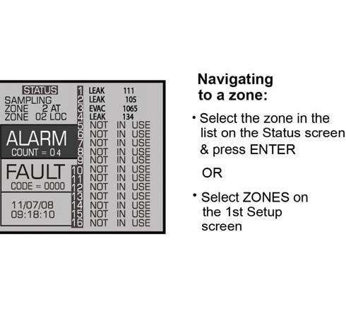
37 SECTION 4. GENERAL OPERATION 4.1. Functional Overview MZ without user input. MZ operate rates. MZ MZ is The Zone Setup Screen System Setup Screen #2, scroll down to select the ZONES option. Figure 4-1. Zone Setup Screen # Location MZ the location. 1. Press the Press Gas/Refrigerant Type the the MZ is 1. Press the Press P/N:


38 Distance + EXH the. 1. Press the Press to accept the new Zone the 1. Press the Press Current Detection Reading the current PPM Log Interval MZ Zone Setup Screen #1. recorded in the trend every measurement cycle, it will contain, increase this Trend Screen 4.3. Navigating to the 2 nd Zone Setup Screen Select the MORE screen t screen. Figure 4-2. Navigating from the First to the Second Zone Screen 32 P/N:
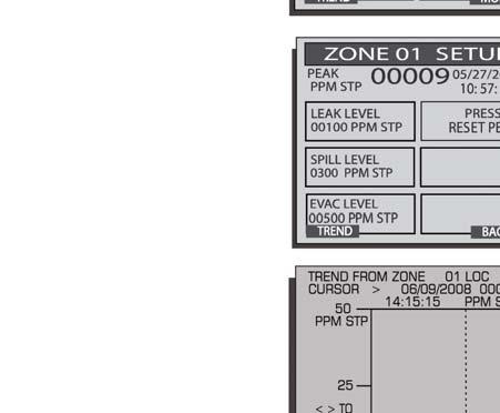
39 Leak Level condition. 1. Press the Press NOTE: l l Spill Level condition. 1. Press the Press NOTE: spill l Evacuation Level condition. 1. Press the Press NOTE: e l Re-Setting the Peak PPM Value screen Alarms Functional Overview condition MZ on the MZ. polls alar. P/N:
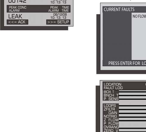
40 Responding to Alarms Alarm Summary Screen. Data Display. Figure 4-3. Alarm Summary Screen Alarm Summary Screen., the additional. indicates an. A, Alarm Detail Screen, press the Alarm Detail Screen. Figure 4-4. Alarm Detail Screen Alarm Detail Screen and current concentration, and date. 34 P/N:
41 at the ACK, a SETUP, to the Zone Setup Screen #1. to the Trend Screen Acknowledging Alarms Alarm Ack Mode on p 26 Alarm Detail Screen and select the ACK option returned to the Alarm Summary Screen. Figure 4-5. Alarm Summary Screen (Acknowledge Mode) MZ the MZ will de- - thresholds are detected Silencing an Alarm and with the d and horns silence S P/N:

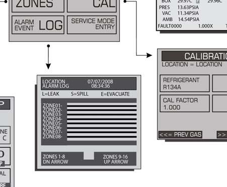
42 Clearing the Alarm Event Log. Data Display Screen, press the UP or Press Alarm Event Log ENTER to select this Alarm Event Log Figure 4-6. Accessing the Alarm Event Log were associated with each as the date condition window. NOTE: System Faults Functional Overview will Connecting External Alarms 23 and Audible Alarm 26. Connecting External Alarms 23 and Audible Alarm 26, the MZ non- MZ the MZ. 36 P/N:
43 Navigating to the Fault Screen Data Display Screen is a Fault this opt Fault Screen. Figure 4-7. Fault Screen Critical Faults Fault Code Description / Possible Causes Go to the Data Display Screen NOTE: there are and their nes is in use, the Indicates s 5.3 on 50. P/N:
44 Non Critical Faults Fault Code Description / Possible Causes Diagnostic Screen Diagnostic Screen Diagnostic Screen record ALL data s. Setup Screen #2 RDM Setup Screen #1 solenoid Reset to Factory Default Settings IMPORTANT:, trends 1. Press and hold down the the MZ p C. 3. is heard. 4. ll indicate conditions MZ in th Clearing System Faults condition is associated with an MZ will t connected to the MZ condition to clear MZ 38 P/N:
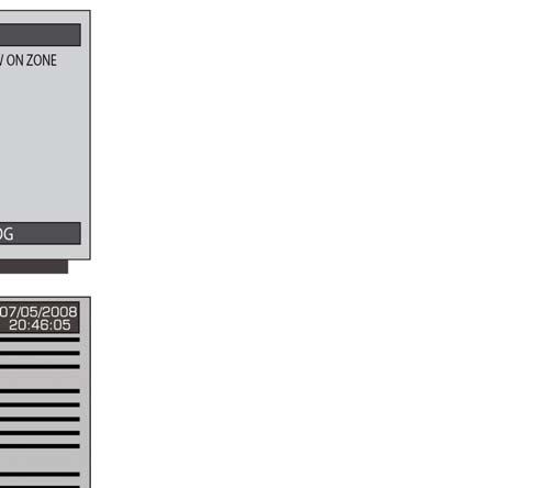
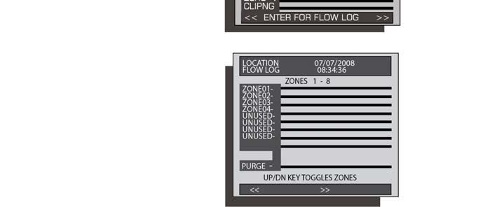
45 Viewing Fault Log conditions. On the Fault Screen, select the LOG option. Figure 4-8. Fault Log Screen NOTE: NOTE: Viewing Flow Log screen last 20. ZONES 1-8 Figure 4-9. Flow Log Screen P/N:

46 scroll data. the date The Trend Screen Navigating to the Trend Screen Zone Screen, select the Trend Trend screen. data - - st Figure Trend Screen NOTE: The Calibration Screen Overview Calibration Screen tion es. 40 P/N:
47 IMPORTANT: will Navigating to the Calibration Screen On, CAL). Figure Calibration Screen (HGM and AGM Only) Calibration Procedure (HGM and AGM Only) PPM.., and place the MZ purposes. to data Adjusting Calibration Factor (HGM and AGM Only) option is ordered. 1. S options 2. option Press ESC P/N:


 IMPORTANT: alter")

48 NOTE: 2 - CO CO 2 Atmospheric Concentration Because CO 2 is prese 2 CO 2 the - locations the. IMPORTANT: CO 2 and will li 2 concentration then the 2 the CO 2 concentrat CO Figure Accessing the CO 2 Atmospheric Concentration Setting (PPM IN PURGE) IMPORTANT: alter the Programming New Gases (HGM Only) As new co MZ ases to its on- Calibration Screen.. 42 P/N:
49 1. Calibration Screen, u Figure Custom Gas Screen (HGM Only) 2. Select the option. Press 3. as 4.8. Zone Hold Mode n, then press and hold down the. in the, the status to that Zone s Setup Screen #1. P/N:
.")
50 4.9. The Diagnostic Screen Navigating to the Diagnostic Screen On the System Setup screen, select DIAG). Figure Diagnostic Screen 44 P/N:
51 Diagnostic Screen Overview Diagnostic Screen conditions each line is listed, Field Name Description xxxx xx ZONE name - -to- line 1. NOISE UM/L PPM AMB y.yyy x.xxxx A 16 point runnin umoles/l -. pressure. Benc rnal enclosure Pressure tput re PSIA. x x xxxxx P/N:
52 46 P/N:


53 SECTION 5. MAINTENANCE WARNING: power the IMPORTANT: Replacement Parts Overview Part Name P/N Description air ala. Line End End- -Line as and as required or p. s - a new one. - -line water stops nts required. P/N:
54 Part Name P/N Description Board is not., disconnect the AC power de 5.2. Replacement Parts and Optional Accessories Replacement Parts Item Description Panas Warning: Part Number : Charcoal, Zero Air : End : End- -line water stop : ¼ in P/N:
55 Item Description Part Number Port 2: Zones 1-4 and p p Port 2: Zones Port Stainless Steel Ma : Zones Optional Accessories Item Description Part Number ilters [ ] Alarms Audio- - Audio- - - Audio - Annual Maintenance Kits Zone,,, 3 end- -line water stop Zone,,, 3 end- -line water stop Zone,,, 3 end- -line water stop Zone, 1 charco 3 end- -line water stop Gases -, 100 PPM , 100 PPM , 100 PPM n Kit P/N:

56 Water Traps Item Description Part Number Communications Kits Kit Kit Troubleshooting Certain critical 1. ccess the Setup Menu 2. to se option. 3. optio Figure 5-1. Sample DIGIPOT Readings 50 P/N:
57 8. IMPORTANT! 6 8 with Press P/N:
58 52 P/N:
59 APPENDIX A. RECOMMENDED REFRIGERANT GAS ALARM SETTINGS Gas Alarm Settings (PPM) Alarm Settings (PPM) Gas Leak Spill Evacuate Leak Spill Evacuate CO N / /CO P/N:
60 54 P/N:
61 APPENDIX B. RS-485 COMMUNICATIONS PROTOCOL B.1. Overview he MZ. B.2. MODBUS RTU Protocol MZ Because t B.3. MZ MODBUS RTU Operation B.3.1. Overview MZ and protocol. 5 MZ data,. MZ MZ. o that the MZ s are conn MZ. NOTE: -Zone. B.3.2. Protocol Details A 2 wire MZ.... nd status i MZ... MZ. MZ. MZ.. MZ tor P/N:
62 . MZ sends the appropriate.,, to insure that are within MZ. IMPORTANT: - - B.3.3. MZ Monitor Polling MZ s.. r all. MZ. MZ - 20 seconds, as there will n. MZ. MZ s, as this could re MZ. B.3.4. Network Topologies MZ. In either case, each MZ. Up to 15 MZ. MZ s are accesse, the. MZ. MZ s it is connected to. MZ s... MZ. In other words, it allows the MZ r. IMPORTANT: It is All screens,,. A this, th was last. he protected so en. B.3.5. Key Comm Protocol Parameters Parameter Description 56 P/N:
63 Parameter Stop Bits Description ,000 NOTE: All data process the - B.3.6. Summary of Registers Register Name Number HEX Decimal Description 16 Status 1 17 and status Set MZ date Put Puts 28 PPM # 06] C I UI Character Data Type Abbreviations P/N:
64 B.3.7. System Data Register 0x0010 (16 Dec) (R/W, 54 Bytes) Variable Type Length Description UI es Indicates UI Node UC -. t is that. Location C C UC Mode UC MZ.. Other Sounds inte. UC. UC UI UC. Concentrations less than or equal this UC.. UI. UI - and MZ or MZ. Mode UI B.3.8. Status Register 0x011 (17 Dec) (R/W, 10 Bytes) Variable Type Length Description Mode UC State UC UC MZ.. DO NOT MODIFY (use zone hold register or service mode register to change this parameter) MZ Current State. DO NOT MODIFY. DO NOT MODIFY UC. 2, etc. UC - DO NOT MODIFY UC. DO NOT MODIFY UC UC DO NOT MODIFY UI 58 P/N:
65 B.3.9. Fault Code Table BIT Fault Type Code Description A Current loop is open 3 error B Zone Data Register 0x12xx (R/W, 78 Bytes) MZ has a separate one. is the low. Variable Type Length Description Location C UC.. DO NOT MODIFY. erant UC UI I erature Concentration DO NOT MODIFY Concentration2 DO NOT MODIFY. UC NOTE: condition will also UC. UI Spill UI UI UI tes UI 2 P/N:
66 NOTE: Recommended Alarm Settings & Gas Enumeration 53. NOTE: unused. B Alarms and Alarm Acknowledge Multi-Zone. MZ. MZ to. 1. Non-Latching Mode. er in the. condition occurs an MZ. MZ MZ w.. MZ al. 2. Latching Mode with Silence.. condition occurs, an MZ. In. MZ. MZ. no 3. Latching Mode without Silence.. condition occurs, an MZ. MZ.. MZ. NOTE: to spill B Date Time Register 0x0015 (21 Dec) (R/W, 14 Bytes) Variable Type Length Description P/N:
67 B Sensor Data Register 0x0016h (22 Dec) (R, 82 Bytes) Variable Type Length Description Pressure 4 4 Pressure sensor 4 on in PSIA Ben UI Noise 4 AU PPM co 4 4 B Release Zone Hold Register 0x0017h (23 Dec) (W, 10 Bytes) Variable Type Length Description * * B Hold Zone Register 0x0018h (23 Dec) (W, 10 Bytes) Variable Type Length Description * * B MZ Hold Mode MZ.. Placing the MZ Monitor into hold mode: 1. MZ 2. e hold. A 3. S MZ Releasing the Zone Hold 1. MZ P/N:
68 2.. A 3. MZ. B Fault Log Register 0x ( Dec) (R, 302 Bytes).... Variable Type Length Description UI. occurrence. Ptr UC Unused UC Unused B Flow Log Register 0x001F (31 Dec) (R, 142 Bytes) Variable Type Length Description UI UC Ptr UC Unused UC Unused B Alarm Log Register 0x1A00-02 ( Dec) (R, 582 Bytes)... Variable Type Length Description UC Ptr UC Unused UC Unused.. Each.. 62 P/N:
69 B Service Mode Register 0x001B (27 Dec) (W, 10 Bytes) Variable Type Length Description * * B Release Service Mode 0x001C (28 Dec) (W, 10 Bytes) Variable Type Length Description * * B MZ Service Mode MZ. are opened.. Placing the unit into Service Mode: 1. MZ 2. e. 3. MZ unit Releasing the unit from Service Mode: 1. MZ MZ unit B PPM Register 0x001E (30 Dec) (R, 32 Bytes) Variable Type Length Description PPM UI MZ NOTE: installed in the nterpret the data. B Zone Log Registers 0x3xyy (R, 1502 Bytes) data structure. P/N:
70 Variable Type Length Description UI points. PPM UI 200 B MODBUS Exception Responses s unit MZ and the is B MODBUS Gas Enumeration Refrigerant Gas DEC HEX Refrigerant Gas DEC HEX CO N A B C E A B C E A A P/N:


71 APPENDIX C. SYSTEM MENU MAP P/N:

72 66 P/N:

73 APPENDIX D. AGENCY APPROVALS P/N:

74 68 P/N:

75 European Standard EN threshold * Based on a minimum tubing length of one foot P/N:
76 70 P/N:
77 APPENDIX E. SERVICE CENTERS United States Bacharach, Inc. Phone Canada Canada Phone: Europe Ireland Phone: E P/N:
78 72 P/N:
79 INDEX NUMBERS , , 47, , , , , , 11, 47, , , 11, 12, 47, i, , 12, 47, outputs/loops... 13, , 48 A AC input power... 2, 8, 13, 14, 23, 24, 38, 47, source... 2, , 23 accessories... 4, 12, a , 33, 34, 35, address... air lines... 11, 31, 48 t , 8, 20, 23, 24, 26, 33-35, 38, 47, 55-60, 62, 63 a ode... 26, , 26, 33, 35, 36 condition... 26, 33, 35, 36, 44, detail screen... 34, , nuisance... 5 set points... 5 s... 53, 60 s screen... 34, uncleared , CO 2 presence... 11, annual aintenance its , , 7 P/N:
80 ...4, 26, 33, 35, 36 B Bacharach s center # , 45, , 8, 15, 17, 18, 21, C , 20, 41, 42, , procedure screen , 11, 37, , 22, , 14 clean air COM1 and COM , 13 concentration condensation conduit... 13, connections... 2, 15, , 37, , 38 current loop... 22, isolator outputs... 21, D data d data point date... -to detector connector , 38, 44, E enu... electrical connections... 13, EN enclosure... end- -line... 4, 12, 47,... 25, 35, , , 33, 53, 58, , 37, , , 24, 33, 36,... 4, , 24 F... 38, , 8, 20, 23, 26, 36-44, 45, 47, 50, P/N:
81 screen iii, 4, 5, 11, 12, 37, , low l panel... 4, 5, 18, 25 indicator... 4, 5, 18, , 13, 24, 47, G as l as/r t , 14, 15, 22 /stud , 14 H... 4, 11, , 43, 57, 61 horn... 24, h , 47 I in installation , 21, , 12 condensation /detector... 13, r it d J J5 connector J6 connector K , 22, 23 L laptop , 23, 26, 33, 42, 53, 58, , 8, 35, 36, LINE LINE line end ilter... 4, 11, 12, l location... 5, 11, 12, 26, 31, 34, 40, , 27 M , 2, 5, , 26, 38, 45, 48 pressure , 32, , , 15, 44, 55, e... 11, 12, 47, cutouts... 4 location..., , , 55 P/N:
82 N... 13, , 17, 28, 30, 31, 34, 35, 38, 55, 56 neutral node address... 17, 28, O outputs P password , 56 patent... ii PCMCIA slot PCMCIA-to , , 16, , , , , 21 de , 45 pressure connector pressure sensor new , , 48, , 10, 11, , , R -123 er and a and and See setup screen # , 7, 11, 47, , 23, 26, 35, 38, 60, 63 connectors... 13, 23 contacts... 4, Module.. 6, 8, 15, 17, 31, 35, 36, 55, repair...iii, 3, , 48 re re , output port... 5, c, connector... 13, 15, S , 12, 37, 47, , , S S Inc , serial port connection centers P/N:
83 set points... 5 setup setup screen # , , 3, solenoid connections ii, iii, 7, 8, 10, 41, 57 spill... 4, 23, 26, 33, 53, 58,, splash screen stand , switches s... 4, 8, , , 27, screen # screen #2...25, 26, 28, 31 screen #3... T n switches , 17 tolerance trend... 20, 32, 38, 40, 41, data... 20, 40, 41 screen... 32, 35, , 11, 12, 45, 47, 48, , restrictions... 5 twisted shielded pair U UPS USB-to-..., 20 V W screen iii, 8 -line... iii... washers water stop... 6, 12, 47, 48, wet installation area X Z , 8, 26, 27, 31, 32, 36-40, 48, 56, 57, current ode setup screen... 5, 12, 31, 32, P/N:
84 -7074 : Printed in U.S.A.
Gas Monitor Multi Zone
 Gas Monitor Multi Zone Instruction 3015-5074 Installation / Operation / Maintenance Rev. 6 November 2010 UL 61010-1 CAN/CSA 22.2 No.61010.1 EN 14624 Product Leadership Training Service Reliability WARRANTY
SECTION 1 (Page 2) Introduction, standard accessories and mounting specifications.
 Introduction, standard accessories and mounting specifications.") HGM300 / RDM800 Refrigerant Monitoring System Instruction 3015-4149 Installation & Operation Mini Manual Rev. 5 November 2004 SECTION 1 (Page 2) Introduction, standard accessories and mounting specifications.
HGM300 / RDM800 Refrigerant Monitoring System Instruction 3015-4149 Installation & Operation Mini Manual Rev. 5 November 2004 SECTION 1 (Page 2) Introduction, standard accessories and mounting specifications.
HGM-MZ Halogen Gas Monitor Multi Zone
 Halogen Gas Monitor Multi Zone HGM-MZ Halogen Gas Monitor Multi Zone Instruction 3015-5074 Installation / Operation / Maintenance UL 61010-1 CAN/CSA 22.2 No.61010.1 Rev. 0 Preliminary November 2008 Product
HGM-RD Remote Display Module: Refrigerant Gas Monitoring System
 HGM-RD Remote Display Module: Refrigerant Gas Monitoring System Instruction 3015-5157 Installation / Operation / Maintenance Rev. A Preliminary- January, 2009 UL 61010-1 CSA 22.2 No. 1010.1 Product Leadership
HGM-RD Remote Display Module for Refrigerant Gas Monitoring System
 HGM-RD Remote Display Module for Refrigerant Gas Monitoring System Instruction 3015-5157 Installation / Operation / Maintenance Rev.0 February, 2009 UL 61010-1 CAN/CSA 22.2 No.61010.1 Product Leadership
MZ-RD Remote Display. Instruction Installation / Operation / Maintenance. Rev. 6 December 2011
 MZ-RD Remote Display Instruction 3015-5157 Installation / Operation / Maintenance Rev. 6 December 2011 UL 61010-1 CAN/CSA 22.2 No.61010.1 Product Leadership Training Service Reliability NOTICE Product
HGM300/RDM800 PREVENTATIVE MAINTENANCE AND TECHNICAL SUPPORT. SECTION 1 HGM300 CPU reset, RDM800 CPU reset, WARM UP notes and HGM300 Self Test
 HGM300/RDM800 PREVENTATIVE MAINTENANCE AND TECHNICAL SUPPORT SECTION 1 HGM300 CPU reset, RDM800 CPU reset, WARM UP notes and HGM300 Self Test SECTION 2 HGM300/RDM800 Mechanical Room layout SECTION 3 HGM300
Rev 4 12-APR IRLDS II and IRLDS II User Interface Installation and Operation Manual
 026-1305 Rev 4 12-APR-2010 IRLDS II and IRLDS II User Interface Installation and Operation Manual 1640 Airport Road, Suite 104 Kennesaw, GA 31044 Phone: 770-425-2724 Fax: 770-425-9319 ALL RIGHTS RESERVED
Two-Channel Gas Controller
 Two-Channel Gas Controller Specifications subject to change without notice. USA 09 Page of DESCRIPTION Highly configurable, UL 0 performance-tested and -certified, and wall-mounted gas monitor; continuously
CO2MSZ Carbon Dioxide Gas Monitor Single Zone
 CO2MSZ Carbon Dioxide Gas Monitor Single Zone Instruction 3015-4603 Installation / Operation / Maintenance Rev 2 - August 2009 Product Leadership Training Service Reliability WARRANTY Bacharach, Inc. warrants
PGM-IR Halogen Monitor Bagless Portable Gas Monitor for Halogen Gases (Refrigerants)
") PGM-IR Halogen Monitor Bagless Portable Gas Monitor for Halogen Gases (Refrigerants) Instruction 3015-5466 Operation and Maintenance Rev. 8 May 2014 Patent 6,590,690 Product Leadership Training Service
PGM-IR Halogen Monitor Bagless Portable Gas Monitor for Halogen Gases (Refrigerants) Instruction 3015-5466 Operation and Maintenance Rev. 8 May 2014 Patent 6,590,690 Product Leadership Training Service
RS485 MODBUS Module 8AI
 Version 1.4 15/04/2013 Manufactured for Thank you for choosing our product. This manual will help you with proper support and proper operation of the device. The information contained in this manual have
Carbon Monoxide Transmitter
 Introduction The CO Transmitter uses an electrochemical sensor to monitor the carbon monoxide level and outputs a field-selectable 4-20 ma or voltage signal. The voltage signal may also be set to 0-5 or
PGM-IR Halogen Monitor
 PGM-IR Halogen Monitor Portable Gas Monitor for Halogen Gases (Refrigerants) Instruction 3015-4584 Operation and Maintenance Rev. 11 December 2015 Patent 6,590,690 Product Leadership Training Service Reliability
Portable area gas monitor with infrared sensor for halogen
 User manual Portable area gas monitor with infrared sensor for halogen Designed to detect and display the concentration of refrigerant gas in the area being monitored www.danfoss.com Index 1.0 Introduction
Danfoss gas detection units
 Data sheet Danfoss gas detection units Types GD Premium, Premium+, Premium Duplex, Premium Remote, Premium Flex and Premium Uptime The Premium line gas detection units are used for monitoring and warning
Installation Guide. Bacharach HGM300 to LonWorks FT-10 Communications Adapter
 3015-4568 Revision 0 9/11/03 Installation Guide Bacharach HGM300 to LonWorks FT-10 Communications Adapter Introduction The Bacharach HGM300 to LonWorks Communications Adapter enables an HGM300 Refrigerant
GLD-30 Gas Leak Detector
 GLD-30 Gas Leak Detector Installation, Operation & Maintenance General: The Archer Instruments GLD-30 is an ambient air monitor, used to detect the presence of a target gas (or gases) and to alert operators
APPLICATION DATA SHEET
 APPLICATION DATA SHEET Control Systems Transmitters Sensors Accessories Wall, 19 Rack or Panel Mounting Units 110/230V 50/60Hz AC operation 250 Addressable devices as: Relays, 4-20 Inputs or Gas Detectors
Danfoss gas detection units
 Data sheet Danfoss gas detection units Types GD Premium, Premium+, Premium Duplex, Premium Remote, Premium Flex and Premium Uptime The Premium line gas detection units are used for monitoring and warning
SCAN200E USER S MANUAL
 SCAN200E USER S MANUAL Code No. 2071 1052 rev. 1.4 Code No. 2071 1052 Rev. 1.4 Page 2/16 SCAN200E User s Manual Foreword This manual is for SCAN200E Controller running software version 2.03 or later. We
ModSync Sequencing System Installation & Operation Manual. For use with Fulton Steam Boilers.
 ModSync Sequencing System Installation & Operation Manual For use with Fulton Steam Boilers. Revision 3.0 8/21/2008 - 2 - Table of Contents Introduction Page 4 Features Page 4 Sequence of Operation Page
FlameGard 5 MSIR HART
 FlameGard 5 MSIR HART Multi-Spectral Infrared Flame Detector HART Communication with the FlameGard 5 Multi-spectral Infrared Detector The information and technical data disclosed in this document may be
Installation Guide Bacharach Communications Adapter HGM-MZ to Johnson Controls Metasys N2 Network (Electrically Isolated N2 Port Version)
") Installation Guide Bacharach Communications Adapter HGM-MZ to Johnson Controls Metasys N2 Network (Electrically Isolated N2 Port Version) 621 Hunt Valley Circle New Kensington, PA 15068 Tel: 724-334-5000
Installation Guide Bacharach Communications Adapter HGM-MZ to Johnson Controls Metasys N2 Network (Electrically Isolated N2 Port Version) 621 Hunt Valley Circle New Kensington, PA 15068 Tel: 724-334-5000
Operations Manual TS400. Test Station for G450/G460 Gas Detector
 TS400 Test Station for G450/G460 Gas Detector Operations Manual 1194 Oak Valley Dr, Ste 20, Ann Arbor MI 48108 USA (800) 959-0329 (734) 769-0573 www.goodforgas.com GfG Products for Increased Safety Congratulations
Macurco DVP-120 / DVP-120M Detection and Ventilation Control Panel User Instructions
 Macurco DVP-120 / DVP-120M Detection and Ventilation Control Panel User Instructions IMPORTANT: Keep these User Instructions for reference. TABLE OF CONTENTS 1 Introduction 4 1.1 DVP-120 General Information
21-light Remote Annunciator. Owner s Manual
 21-light Remote Annunciator Owner s Manual Annunciator Description... Inside Font Cover Detailed Specifications... 1 Environmental Specifications... 1 Power Supply Requirements... 1 Communication With
Gas Controller Module GC-06
 Page 1 Oct. 2015/2 Measuring, warning and controlling module for toxic, combustible and refrigerant gases and vapours. The gas controller series GC-06 is designed in accordance with the standard EN 50545-1.
Mark 25 Ultrapure Water Conductivity Analyzer
 Martek Instruments, Inc. Mark 25 Ultrapure Water Conductivity Analyzer Instruction Manual WARRANTY POLICY Unless otherwise stated, MARTEK INSTRUMENTS, INC. warrants this equipment to be free from defects
P2267 NETWORK INTERFACE
 P2267 NETWORK INTERFACE USER MANUAL FOR OPERATING SYSTEMS: 22031-03 23636-01 October 2009 Associated Controls (Australia) Pty. Limited 2-4 Norfolk Road Greenacre, NSW, 2190. PH +61 2 9642 4922, FAX +61
Recalibrate the way you look at gas detection
 Catalogue Gas detection solution Recalibrate the way you look at gas detection Next generation gas detection for industrial refrigeration The next generation of Danfoss gas detectors are based on a digital
20 Light Remote Annunciator
 Light Remote Annunciator Owner s Manual Surface Mount Flush Mount 94-95- Standard Annunciator 94-, 94-95-, 95-4- 4- Annunciator w/remote Relay Panel 4-, 4-4-, 4-49-, 49-49-, 49- Time Multiplexed Annunciator
Replaceable LED modules. Sleep or unattended mode. Auto-silence and auto-acknowledge
 Replaceable LED modules 11 Alarm Sequences as per ISA-18.1 standard Each channel/window fully field programmable RS232 or RS485 MODBUS-RTU communication Repeat relay for each window and multifunction relays
MODEL 4300-PG CENTRAL ACCESS PANEL FOR EC-GOLD TRANSMITTERS. User Manual
 MODEL 4300-PG CENTRAL ACCESS PANEL FOR EC-GOLD TRANSMITTERS User Manual Technical Support Continental North America Toll Free 1-(800) 387-9487 Ph: +1 (905) 829-2418 Fx: +1 (905) 829-4701 A Product of Arjay
TYPE CM-2201 NELSON SINGLE POINT CIRCUIT MANAGEMENT SYSTEM
 2 Line, 16 Characters/row LCD Display Temperature Input Range -50 C to +500 C -58 F to + 932 F Enclosure NEMA Type 4X Current Rating 30A max (resistive load only) Ambient Temperature -40 C to + 40 C -40
Nitrogen Dioxide (NO2) Single-Point Gas Detection System
 Single-Point Gas Detection System") Nitrogen Dioxide (NO) Single-Point Gas Detection System DESCRIPTION Wall-mounted gas monitor with built-in nitrogen dioxide (NO)/diesel fume gas sensor, accepts one analog remote device such as a secondary
Nitrogen Dioxide (NO) Single-Point Gas Detection System DESCRIPTION Wall-mounted gas monitor with built-in nitrogen dioxide (NO)/diesel fume gas sensor, accepts one analog remote device such as a secondary
PROCESS & TEMPERATURE UNIVERSAL INPUT DIGITAL METERS
 PROCESS & TEMPERATURE UNIVERSAL INPUT DIGITAL METERS NOVA PD56 Series Thermocouple, RTD, & Process Inputs Universal Power Supply 1-24 VAC Up to 3 Alarm Relays Retransmitting 4-2 ma Output Input Max/Min
MX43. Analog and digital controller. 4 or 8 lines / 16 to 32 detectors max. Highly versatile controller. Cost savings on wiring installation
 Gas Detection Control Panel MX Analog and digital controller or 8 lines / 6 to s max Highly versatile controller Cost savings on wiring installation The Fixed Gas Detection People www.oldhamgas.com an
APPLICATION DATA SHEET
 APPLICATION DATA SHEET Wed : www.saenchotesei.com WWW.-..UK Control Systems Transmitters Sensors Accessories TOCSIN 920 - Wall, 19 Rack or Panel Mounting Units - 110/230V 50/60Hz AC operation - 250 Addressable
Superdew 3. Hygrometer. Operating Instructions
 Superdew 3 Hygrometer Operating Instructions Shaw Moisture Meters (UK) Ltd Len Shaw Building Bolton Lane Bradford BD2 1AF England t. +44 (0) 1274 733582 f. +44 (0) 1274 370151 e. mail@shawmeters.com www.shawmeters.com
Process & TeMPerATUre UniversAl input DigiTAl MeTers
 Process & TeMPerATUre UniversAl input DigiTAl MeTers nova PD56 series Thermocouple, rtd, & Process inputs Universal Power supply 1-24 va c Up to 3 Alarm relays retransmitting 4-2 ma output input Max/Min
Danfoss gas detection unit Type GD Heavy Duty
 Data sheet Danfoss gas detection unit Type GD Heavy Duty The Heavy Duty gas detection units are used for monitoring and warning of hazardous Ammonia gas concentrations. They are intended for ATEX/ IECEx
NGC-UIT2 MODBUS PROTOCOL INTERFACE MAPPING FOR NGC-30 SYSTEMS. Firmware versions up to V2.0.X
 NGC-UIT2 MODBUS PROTOCOL INTERFACE MAPPING FOR NGC-30 SYSTEMS Firmware versions up to V2.0.X INDUSTRIAL HEAT TRACING SOLUTIONS EN-RaychemNGCUIT2Protocol-IM-H57880 06/15 1/32 Contents Section I Introduction
HALOGUARD IR MULTI-POINT, COMPOUND SPECIFIC MONITOR INSTRUCTION MANUAL
 HALOGUARD IR MULTI-POINT, COMPOUND SPECIFIC MONITOR INSTRUCTION MANUAL S E R I A L N O. M O D E L N O. T e m p. R a n g e 1 - = > 6 0 o F 2 - = 4 0-6 0 o F 3 - = < 4 0 o F - G a s T y p e 1 - R -1 1 2
Meridian wiredhart. HART Field Device Specification Goldmine Rd. Monroe, NC USA
 HART Field Device Specification Meridian wiredhart 4320 Goldmine Rd. Monroe, NC 28110 USA HART is a registered trademark of the HART Communication Foundation TABLE OF CONTENTS 1. Introduction...5 1.1 Scope...5
Analog and digital controller. 4 or 8 lines / 16 to 32 detectors max. Highly versatile controller. Cost savings on wiring installation
 Gas Detection Control Panel Analog and digital controller 4 or 8 lines / 6 to detectors max Highly versatile controller Cost savings on wiring installation Certifications The The Fixed Fixed Gas Gas Detection
4-20mA CYBER Cyber Transmitter for flammable, toxic and IR gas detection Cyber Head Increased security in ATEX certified head
 4-20mA CYBER Cyber Transmitter for flammable, toxic and IR gas detection Cyber Head Increased security in ATEX certified head NET DRAFT version 2.1-2008 Pag. 1 4-20mA Cyber - DRAFT version 2.1-2008 Pag.
CONsOlIDATOR 4 & 8. MulTI- C h ANNEl CONTROllERs. ConsoliDator 4 Model PD940 ConsoliDator 4 Features. ConsoliDator 8 Features.
 CONsOlIDATOR 4 & 8 MulTI- C h ANNEl CONTROllERs ConsoliDator 4 Model PD940 ConsoliDator 4 Features Four 4-20 Four 4-20 Outputs ConsoliDator 8 Features Eight 4-20 Two 4-20 Outputs Common Features Four Pulse
D8024, D9024, D10024 Analog Fire Alarm Control Panels Programming Guide
 System Reset Trou ble Silence Ala rm Silence Manual Ala rm ENTER NO YES Letters Numb ers Keyword Radionics System Reset Trouble Silence Alarm Silence Manual Alarm ENTER NO YES Le ters Numbers Keyw ord
APC BC300 Series 40kW 208/450/480V User Guide
 APC BC300 Series 40kW 208/450/480V User Guide Copyright 2002 APC Denmark ApS This manual is subject to change without notice and does not represent a commitment on the part of the vendor Thank You Thank
Oxygen (O2) Single-Point Gas Detection System
 Single-Point Gas Detection System") Oxygen (O) Single-Point Gas Detection System DESCRIPTION Wall-mounted gas monitor with built-in oxygen (O) sensor, accepts one analog remote device such as a secondary gas sensor, temperature or humidity
Oxygen (O) Single-Point Gas Detection System DESCRIPTION Wall-mounted gas monitor with built-in oxygen (O) sensor, accepts one analog remote device such as a secondary gas sensor, temperature or humidity
USER MANUAL FOR OPERATING SYSTEM
 P2262 ALARM PANEL USER MANUAL FOR OPERATING SYSTEM 21765-07 September 1999 Associated Controls (Aust) PTY. LTD. 29 Smith Street, Hillsdale, NSW, 2036. PH (02) 9311 3255, FAX (02) 9311 3779 Page 1 of 177
PGM-IR CO 2 Monitor. Instruction Operation and Maintenance. Portable Gas Monitor for Carbon Dioxide (CO 2 ) Gas. Rev.
 Gas. Rev.") PGM-IR CO 2 Monitor Portable Gas Monitor for Carbon Dioxide (CO 2 ) Gas Instruction 3015-9000 Operation and Maintenance Rev. 4 March 2016 Patent 6,590,690 Product Leadership Training Service Reliability
PGM-IR CO 2 Monitor Portable Gas Monitor for Carbon Dioxide (CO 2 ) Gas Instruction 3015-9000 Operation and Maintenance Rev. 4 March 2016 Patent 6,590,690 Product Leadership Training Service Reliability
Digital Gas Transmitters with Auxiliary Inputs & Control. PolyGard 2 DC6
 Digital Gas Transmitters with Auxiliary s & Control Specifications subject to change without notice. USA 181011 Page 1 of 5 DESCRIPTION Digital RS-485 communicating, addressable toxic and combustible gas
Centaur TM II Cube Slave Alarm Signalling Equipment INSTALLATION GUIDE
 Centaur TM II Cube Slave Alarm Signalling Equipment INSTALLATION GUIDE General Description This guide provides a summary for installing and configuring the Centaur TM Cube Slave Alarm Signalling Equipment
FIRECLASS Networking. Addressable Fire Alarm Control Panels From Software version 21. Product Application and Design Information FC-A-FCNET-A
 FIRECLASS Networking Addressable Fire Alarm Control Panels From Software version 21 Product Application and Design Information FC-A-FCNET-A Doc. version 1 23. March 2012 FIRECLASS. Hillcrest Business Park,
5New features & EXtreme design, now with HART Protocol and DuraSource Technology. Ultima X Series Gas Monitors
 Ultima X Series Gas Monitors Versatile fixed instruments provide continuous monitoring of many hazardous gases using catalytic, electrochemical, and infrared gas detection methods. HART Protocol is now
Important Supplementary Manual to the main Ezeio manual. 5. Section 2a: Introducing the 2400 input and output expansion field stations.
 1 P age Ezeio v9-120317 Eze Cloud Based Monitoring Systems. Created by Intech Instruments Ltd December 2014 Important Supplementary Manual to the main Ezeio manual. Ezeio Controller and the 2400-A16 input
FlameGard 5 UV/IR HART
 FlameGard 5 UV/IR HART HART Communication Manual The information and technical data disclosed in this document may be used and disseminated only for the purposes and to the extent specifically authorized
Installation & Maintenance
 Installation & Maintenance CM.comm Host Communications Software Table Of Contents System Overview System Features System Requirements Communications Overview CM.comm Quick Start Hardware Setup RS-232 Identification
NGC-40 PANEL MOUNTED ADVANCED MODULAR HEAT-TRACING CONTROL SYSTEM HTC HTC3
 NGC-40 PANEL MOUNTED ADVANCED MODULAR HEAT-TRACING CONTROL SYSTEM Local configuration and monitoring with Raychem Touch 1500 touch screen display PRODUCT OVERVIEW The Raychem NGC-40 is a multipoint electronic
SIL 2. Ultima X Series Gas Monitors CERTIFIED
 Ultima X Series Gas Monitors 5 Now with SIL 2 CERTIFIED Products Versatile fixed instruments provide continuous monitoring of many hazardous gases using catalytic, electrochemical, and infrared gas detection
CLEANROOM MONITOR CR3A Network - Installation Instructions
 CLEANROOM MONITOR CR3A Network - Installation Instructions INTRODUCTION The CR3 Series Cleanroom Monitor, was developed specifically to allow for monitoring of confined spaces with accuracy and reliability.
Ammonia Leak Detector Manual
 Ammonia Leak Detector Manual Document No. 70-PHW-1023-R2.5 No part of this publication may be reproduced, stored in a retrieval system, or transmitted, in any form or by any means, electronic, mechanical,
Gas Detection System TOX ALARM DG2000-Garage
 Gas Detection System TOX ALARM DG2000-Garage Gas Detection System 32 independent programmable channels 2 programmable alarm levels for each gas = up to 6 for each channel LCD alphanumeric display of gas
Compod. Instruction Manual IM-COMPOD Revision: F, December 2015
 Compod Programmable Control Module For 100 Series Digital Mass Flow Meters & Controllers Instruction Manual IM-COMPOD Revision: F, December 2015 CORPORATE HEADQUARTERS 5 Harris Court, Building L, Monterey,
NGC-40 Advanced Heat-Tracing Control System
 NGC-40 Advanced Heat-Tracing Control System Local configuration and monitoring with Raychem Touch 1500 touch screen display Heat-tracing system NGC-40 system Remote configuration and monitoring with Raychem
HTC-915-CONT. Heat-Trace Control system
 Heat-Trace Control system Product overview The Raychem HTC-915 system is a compact, full-featured microprocessor-based single-point heat-trace controller. The HTC-915-CONT provides control and monitoring
Engineering Guideline. pac-carriers Type SIEMENS ET-200M Fail-safe signal modules
 Engineering Guideline pac-carriers Type 9195 SIEMENS ET-200M Fail-safe signal modules pac-carrier Type 9195 2 Engineering Guideline/SIEMENS 19.05.2015 pac-carrier Type 9195 Integration of conventional
Inc Series Digital Gas Detector/Controller. Operation Manual
 5 Series Digital Gas Detector/Controller Operation Manual TABLE OF CONTENTS 1. 2. 3. 4. 5. 6. 7. General Description 1.1 Applications 1.2 Features Model Selection Guide Characteristics Installation 4.1
MX43. Analog and digital controller. 4 or 8 lines / 16 to 32 detectors max. Highly versatile controller. SIL1 reliability. Gas Detection Control Panel
 Gas Detection Control Panel MX Analog and digital controller or 8 lines / 6 to s max Highly versatile controller SIL reliability Fixed The Fixed Gas Gas Detection Detection Experts People www.oldhamgas.com
DIGITAL TEMPERATURE RELAY TR-100
 LTD Research-and-Manufacture Company DIGITAL TEMPERATURE RELAY USER S MANUAL www.novatek-electro.com - 2 - Service manual is intended for getting acquaints with hardware, operation principals, modes of
NGC-40 PANEL MOUNTED ADVANCED MODULAR HEAT-TRACING CONTROL SYSTEM HTC HTC3 PRODUCT OVERVIEW
 NGC-40 PANEL MOUNTED ADVANCED MODULAR HEAT-TRACING CONTROL SYSTEM Local configuration and monitoring with Raychem Touch 1500 touch screen display PRODUCT OVERVIEW The nvent RAYCHEM NGC-40 is a multipoint
SEC 2000 Millenium Infrared Gas Detector
 SEC 2000 Millenium Infrared Gas Detector Instruction and Operation Manual Sensor Electronics Corporation 5500 Lincoln Drive Minneapolis, Minnesota 55436 USA (952) 938-9486 Fax (952) 938-9617 Email: sales@sensorelectronic.com
IT COULD FAIL TO PERFORM AS DESIGNED AND PERSONS WHO RELY ON THIS PRODUCT FOR THEIR SAFETY COULD SUSTAIN SEVERE PERSONAL INJURY OR DEATH.
 Chillgard LC Control Module Instruction Manual "! WARNING THIS MANUAL MUST BE CAREFULLY READ BY ALL INDIVIDUALS WHO HAVE OR WILL HAVE THE RESPONSIBILITY FOR INSTALLING, USING, MAINTAINING OR SERVICING
TEMPERATURE CONTROLLER (STANDARD MODEL)
") OPERATING MANUAL TEMPERATURE CONTROLLER (STANDARD MODEL) 689-0000 689-0005 Barnant Company 28W092 Commercial Avenue Barrington, Illinois U.S.A. 60010-2392 (847) 381-7050 (847) 381-7053 (Fax) 800-637-3739
OPERATING MANUAL TEMPERATURE CONTROLLER (STANDARD MODEL) 689-0000 689-0005 Barnant Company 28W092 Commercial Avenue Barrington, Illinois U.S.A. 60010-2392 (847) 381-7050 (847) 381-7053 (Fax) 800-637-3739
Series DCT1000DC Dust Collector Timer Controller Specifications Installation and Operating Instructions
 Series DCT1000DC Dust Collector Timer Controller Specifications Installation and Operating Instructions Bulletin E-97DC Thank you for purchasing the Dwyer DCT1000DC Dust Collector Timer Controller. You
Models NFPA 1221-A, NFPA 1221-B Public Safety DAS Annunciator Panel. Revision E 61117
 Models NFPA 1221-A, NFPA 1221-B Public Safety DAS Annunciator Panel Revision E 61117 CAUTION: (Read This First) This panel has been designed to make it nearly bullet proof to mistakes made when wiring
Beacon 200 Gas Monitor Operator s Manual. Part Number: RK Released: 6/6/08
 Beacon 200 Gas Monitor Operator s Manual Part Number: 71-2102RK Released: 6/6/08 Table of Contents Chapter 1: Introduction.................................................3 Overview.............................................................3
Combustible Gas Detection and Control System
 Combustible Gas Detection and Control System DESCRIPTION Gas monitor with built-in combustible gas sensor, wall-mounted, accepts inputs from remote devices such as other gas sensors, temperature or humidity
Multi-Gas-Controller MGC2
 Page 1 Aug. 2018 Gas measuring, monitoring and warning controller based on state-of-the-art micro-technology for continuous monitoring of the ambient air to detect toxic and combustible gases, refrigerants
Chillgard Refrigerant Monitor
 Chillgard 5000 Refrigerant Monitor Chillgard 5000 7 Mechanical Equipment Room Gas Monitoring Stay in compliance with ASHRAE 15, the Environmental Protection Agency and local building codes with the Chillgard
Addendum HART Communication with the X2200 UV Flame Detector 1.1 4/
 Addendum HART Communication with the X2200 UV Flame Detector 1.1 4/09 Table Of Contents Interconnecting the HART Communicator with the Detector.... 1 HART Device Description Language.... 3 Detector Wiring.......................................
Warranty Registration
 WARRANT Y AND LIMITS OF LIABILIT Y Vulcain Inc. warrants to the original purchaser that its product, and the component parts thereof, will be free from defects in workmanship and materials for a period
Pioneer-R16 Gas Monitor Operator s Manual
 Pioneer-R16 Gas Monitor Operator s Manual Edition 7/2/97 RKI INSTRUMENTS, INC RKI Instruments, Inc. 33248 Central Ave, Union City, CA 94587 (510) 441-5656 Chapter 1: Description About the Pioneer-R16 Gas
Adaptive CyCLO Technical and HMI User Guide. CyCLO User Guide. Version th December 2017 REV
 CyCLO User Guide Version 2.00 19 th December 2017 REV 2.00 1 Contents 1. Hardware... 3 1.1. Introduction... 3 1.2. Electrical Specification... 3 1.3. Board Overview... 4 1.4. Electrical Installation...
Q-SMART MODBUS KIT. Modbus Protocol & Parameters. Cod EN rev.a ed.08/2018. Q-SMART Software Version AE17
 Q-SMART MODBUS KIT Modbus Protocol & Parameters Cod.001085120EN rev.a ed.08/2018 Q-SMART Software Version AE17 Index 1 Modbus Protocol on Q-SMART... 4 1.1 Broadcasting... 4 1.2 Data Protection... 4 1.3
Operations Manual TS400. Test Station for G450/G460 Gas Detector
 TS400 Test Station for G450/G460 Gas Detector Operations Manual 1194 Oak Valley Dr, Ste 20, Ann Arbor MI 48108 USA (800) 959-0329 (734) 769-0573 www.gfg-inc.com GfG Products for Increased Safety Congratulations
WARRANT Y AND LIMITS OF LIABILIT Y Vulcain Inc. warrants to the original purchaser that its product, and the component parts thereof, will be free fro
 A d e v i h c r D c o n e m u WARRANT Y AND LIMITS OF LIABILIT Y Vulcain Inc. warrants to the original purchaser that its product, and the component parts thereof, will be free from defects in workmanship
Operating & Maintenance Manual. Alert-4 Ethernet LCD Master Alarm
 Operating & Maintenance Manual Alert-4 Ethernet LCD Master Alarm w w w. a m i c o. c o m Contents User Responsibility 4 Introduction 4 Features 5 Description of the Alarm 5 Shipment Details 5 The Alarm
EMS510 Electrical Wiring Guide Volume 2, Rev 1.4
 EMS510 Electrical Wiring Guide Volume 2, Rev 1.4 Prepared by Michael L. Kominske Environmental Monitor Service Inc. PO Box 4340 Yalesville, CT 06492 Phone 203.935.0102 Fax 203.634.6663 Email: sales@emsct.com
BS-316. Gas detection control panel up to 16 inputs. Installation operation manual
 BS-316 Gas detection control panel up to 16 inputs Installation operation manual Page 1 from 21 Contents 1 Operation instructions--------------------------------------------------------------------------------------------------------------------3
Wallace & Tiernan Controllers & Analysers ChemTrim Disinfection Controller
 Wallace & Tiernan s & Analysers ChemTrim Disinfection Introduction The ChemTrim Disinfection is a modern, dedicated controller incorporating the latest advanced electronics and process control application
Toxic and Explosive Smart Gas Monitor PN / Installation and User Manual
 Toxic and Explosive Smart Gas Monitor PN 151022/151023 Installation and User Manual Quest Controls, Inc. 208 9 th Street Dr. West Palmetto, FL 34221 www.questcontrols.com Phone: (941) 729-4799 Fax: (941)
INSTALLATION AND OPERATION MANUAL ENVIRONMENTAL SYSTEM IR-SNIF-MCD MODELS MCD-1, 4, 8 & 16
 SenTech Corporation 5745 Progress Road Indianapolis, Indiana 46241 888/248-1988 FAX 317/248-2014 INSTALLATION AND OPERATION MANUAL ENVIRONMENTAL SYSTEM IR-SNIF-MCD MODELS MCD-1, 4, 8 & 16 APPLICABILITY
Product Data Sheet. Remote Terminals. Features:
 Remote Terminals Product Data Sheet Features: Based around two core products, the Mx- 4010 Remote Display Terminal (RDT) and the fully functional Mx-4020 Remote Control Terminal (RCT). Both remote terminals
THX-DL Data Logger USER & INSTALLATION MANUAL V
 THX-DL Data Logger USER & INSTALLATION MANUAL V1.2012 www.thermomax-refrigeration.com Contents PRESENTATION Summary of Features 2 INSTALLATION Safety Precautions 4 THX Unit 4 Sensors 4 Alarm Relay 4 Power
Model OI-6000K Sensor Assembly
 Model OI-6000K Sensor Assembly Operation Manual Revision 2.0w Product Overview The Otis Instruments, Inc. Model OI-6000K Gen II ambient air gas sensor assembly is a 2-relay wired (Notis) sensor assembly
Sensor unit MC2 with analog output for Freon gases and refrigerants
 Page 1 Dec. 2018 Sensor unit MC2 with analog output for Freon gases and refrigerants Exchangeable sensor unit including digital value processing and self control for the continuous monitoring of the ambient
Series Temperature Controller Instruction Sheet
 Series Temperature Controller Instruction Sheet Thank you very much for purchasing DELTA A Series. Please read this instruction sheet before using your A series to ensure proper operation and please keep