AGENDA. NEC Code-Making Panel 14. Report on Proposal Meeting. January 16-21, Hilton Head, SC
|
|
|
- Lorin Noreen Townsend
- 5 years ago
- Views:
Transcription

1 National Fire Protection Association 1 Batterymarch Park, Quincy, MA Phone: Fax: AGENDA NEC Code-Making Panel 14 Report on Proposal Meeting January 16-21, 2012 Hilton Head, SC Item No. Subject Call to Order Introduction of Members and Guests Review of Meeting Procedures and Revision Schedule Comments/Questions from Committee Members and/or Guests Task Group Reports (if any) Processing of Proposals Fire Protection Research Foundation Requests Old Business New Business Adjournment
2 Chair Report 11/23/2011 Log Proposal No. Code Reference Log Proposal No. Code Reference 1170m 14-1 Entire Document (B)(1) 921m 14-2 Entire Document (B)(2) 2638e Explosionproof Equipment, Table (C)(6) Bulk Plant or Terminal Mobile Equipment, Motor Fuel Dispensing Portable Equipment (New) Spray Booth (New) and Associated Nonincendive Nonincendive Field (B), Informational Note (B), Informational Note (A), Informational Note (A), Informational Note (B)(3), Informational Note (J), (K), and (L) (New) (K) , Informational Note (B)(1) (C)(4) (D)(1) (D)(1), Informational Note (E)(1) (E)(2) , , and , , and (A)(1)(e) (New) (A)(1)(e) (New) (A)(2) (A)(2) (B)(1)(5) (B)(1)(7) (New) (B)(2) (B)(2) (B)(2) and (B) (B)(2)(4) and (B)(3), (B), and and (A)(4) (C)(6) (D)(2) (E)(1) (E)(1) (F)(2) (C)(1)(a) , Informational Note (B) (B)(2) Exception (B)(6) (B)(6) (B)(1)(4) (B)(3) , Informational Note , Informational Note (A) (B) (B), Informational Note (B), Informational Note (B)(1) (B)(4) Exception (B)(1)(1) (B)(1)(1) Exception No (A) (B)(4) (New) and (A) (A)(1), (B)(1), (A)(1)(5) (New) (A)(2)(5) (A)(2)(2), (A)(2), (A)(2)(3) and (B)(1)(2) (B)(1)(8) (New) 1
3 Chair Report 11/23/2011 Log Proposal No. Code Reference Log Proposal No. Code Reference (B) Exception (B)(3) (A)(2) (A) (A) (A)(1)(1) (A)(1) and (A)(1) and (A)(3)(2), (A)(3), (A)(3) and (A), (A)(4) (B) (B) (B) Exception No , Informational Note Associated Apparatus (B) (B) (B) (A)(1) and (A)(2) (A)(1), Informational (A)(1) Exception No (A)(1) Exception No (A)(1) Exception No (A)(1) Exception No. 4, (A)(1) Exception No. 4, (A) and (B) Optical Radiation , Informational Note (A), Informational Note (B), Informational Note (B), Informational Note (B)(1)(2), Informational (B)(2) , Informational Note (B) , Informational Note Informational Note and (I) (I), Informational Note , Informational Note Table 505.9(C)(1)(2) and Table (C)(2) (C)(2) Table 505.9(C)(2)(4) Table 505.9(C)(2)(4) (C)(2) Exception No (D) (D)(1) Exception No (E)(1) (E)(2) (G) , and , and (A) (A) and (B)(1)(g) (B)(1)(g) (New) (B)(1)(g) (New) (B)(1)(g) (New) (C) and (C)(1)(f) (C)(1)(b) (C)(1)(h) (New) (C)(2), (B), and (C)(2) and (C), (B)(5) (B)(6) (C)(2)(a) (C)(2)(b), Informational (D)(5) 2
4 Chair Report 11/23/2011 Log Proposal No. Code Reference Log Proposal No. Code Reference (E)(2) (C) (New) (C) (New) (C) Exception No. 4, (C) Exception No (D) (New) , Informational Note (B) , Informational Note (4) (New) , Informational Note Associated Nonincendive Circuit, Nonincendive Circuit, Nonincendive Field Protection by Protection by Intrinsic Protection by Intrinsic (New) (B)(2) and (3) (E) (H) (C)(1)(2), 506.9(C)(2)(4), (C)(2)(3) Table 506.9(C)(2)(3) (C)(2)(3) (C)(2) Exception No (D) (E)(1) (A) and (C) (A) and (C) (A)(6), (B), and (A)(6) (A)(6) Exception and (A)(7) (New) (C)(2) (C)(6) (C)(7) (C)(9) (New) (D) (New) (B) (A)(1) (A)(1) (A)(1) (A)(1) (A)(1) (A)(1) (F) (B) (D)(1) Table 514.3(B)(1) (C) (New) (A) , Informational Note and A Spray Area, Spray (C)(2)(a) (C)(2)(b) Figure 516.3(C)(2)(a) Figure 516.3(C)(2)(b) (B) (B) (C) (New) (B)(4) 3
5 14-1 Log #1170m NEC-P14 Russell LeBlanc, The Peterson School In articles 90 through 830, if the wording is not already there, then add the words (or other structure(s)) after the word BUILDING(S) wherever the intent of the requirement is to also include STRUCTURES as well as buildings. There is a flaw in the NEC. The term "building" is used over 1000 times in the NEC, and in most of the cases the words "or other structure" should follow and apply the same requirements to bridges, billboards, towers, tanks, and other structures that are by definition NOT BUILDINGS. One specific example I can use is section Wiring on Buildings. I believe that this section is also intended to be applied structures, but the wording "or other structures" is not in the heading or the paragraph. There are literally thousands of other instances throughout the code that this same problem exists. This can easily be seen by doing an electronic search for the word "building". In some cases the words "or other structure" (or similar wording) are present, but in the vast majority where the requirements should also be applied to structures other than buildings, the wording is not there Log #921m NEC-P14 Joe Tedesco, Boston, MA The term "adequate" and "adequately" and "inadequately" and "inadequate" should be replaced with terms that can be properly enforced and understood. Terms are not defined and are considered vague and unenforceable per Table in the NEC Style Manaual. They are all "incorrect" 148 times in the NEC. 1
6 14-3 Log #2638e NEC-P14 John R. Kovacik, Underwriters Laboratories Inc. Update the references to UL Standards in the Informational Notes as shown below: Equipment enclosed in a case that is capable of withstanding an explosion of a specified gas or vapor that may occur within it and of preventing the ignition of a specified gas or vapor surrounding the enclosure by sparks, flashes, or explosion of the gas or vapor within, and that operates at such an external temperature that a surrounding flammable atmosphere will not be ignited thereby. Informational Note: For further information, see ANSI/UL , For purposes of Articles 500 through 504 and Articles 510 through 516, the following definitions apply. Equipment enclosed in a manner that excludes dusts and does not permit arcs, sparks, or heat otherwise generated or liberated inside of the enclosure to cause ignition of exterior accumulations or atmospheric suspensions of a specified dust on or in the vicinity of the enclosure. Informational Note: For further information on dustignitionproof enclosures, see Type 9 enclosure in ANSI/NEMA ,, and ANSI/UL ,. Informational Note: For further information, see ANSI/UL ,. Informational Note No. 2: Female NPT threaded entries use a modified National Standard Pipe Taper (NPT) thread with thread form per ANSI/ASME B ,. See ANSI/UL ,. A circuit in which any spark or thermal effect is incapable of causing ignition of a mixture of flammable or combustible material in air under prescribed test conditions. Informational Note: Test conditions are described in ANSI/UL ,. For purposes of this article, the following definitions apply. Equipment enclosed in a manner that excludes dusts and does not permit arcs, sparks, or heat otherwise generated or liberated inside of the enclosure to cause ignition of exterior accumulations or atmospheric suspensions of a specified dust on or in the vicinity of the enclosure. Informational Note: For further information on dustignitionproof enclosures, see Type 9 enclosure in ANSI/NEMA ,, and ANSI/UL ,. References to UL Standards in the NEC should reflect the current edition. 2
7 14-4 Log #1611 NEC-P14 James F. Williams, Fairmont, WV That portion of a property where liquids are received by tank vessel, pipelines, tank car, or tank vehicle and are stored or blended in bulk for the purpose of distributing such liquids by tank vessel, pipeline, tank car, tank vehicle, portable tank, or container. [ ] Informational Note: For further information, see NFPA ,. That portion of a property where liquids are received by tank vessel, pipelines, tank car, or tank vehicle and are stored or blended in bulk for the purpose of distributing such liquids by tank vessel, pipeline, tank car, tank vehicle, portable tank, or container. [ ] Informational Note: For further information, see NFPA ,. The defined term is referenced in several articles of the NEC:,,,,, & In general, Article 100 shall contain definitions of terms that appear in two or more other articles of the Log #1609 NEC-P14 James F. Williams, Fairmont, WV Equipment with electrical components suitable to be moved only with mechanical aids or is provided with wheels for movement by person(s) or powered devices. Equipment with electrical components suitable to be moved by a single person without mechanical aids Equipment with electrical components suitable to be moved only with mechanical aids or is provided with wheels for movement by person(s) or powered devices. Equipment with electrical components suitable to be moved by a single person without mechanical aids The defined term is referenced in several articles of the NEC:,,,,,,,,,,, (3),,,,,,, (2),, 513.2, & 513.,,, (8),,,,,, (1), (5),,, (6),,,,,,,,,,,,,,,,,,,,,,,,,,,,,,,,,,,, & In general, Article 100 shall contain definitions of terms that appear in two or more other articles of the. 3
8 14-6 Log #1610 NEC-P14 James F. Williams, Fairmont, WV That portion of a property where motor fuels are stored and dispensed from fixed equipment into the fuel tanks of motor vehicles or marine craft or into approved containers, including all equipment used in connection therewith. [ ] Informational Note: Refer to Articles 510 and 511 with respect to electrical wiring and equipment for other areas used as lubritoriums, service rooms, repair rooms, offices, salesrooms, compressor rooms, and similar locations. That portion of a property where motor fuels are stored and dispensed from fixed equipment into the fuel tanks of motor vehicles or marine craft or into approved containers, including all equipment used in connection therewith. [ ] Informational Note: Refer to Articles 510 and 511 with respect to electrical wiring and equipment for other areas used as lubritoriums, service rooms, repair rooms, offices, salesrooms, compressor rooms, and similar locations. The defined term is referenced in several articles of the NEC:,,,,,,,,,, & In general, Article 100 shall contain definitions of terms that appear in two or more other articles of the Log #2894 NEC-P14 James F. Williams, Fairmont, WV Equipment with electrical components intended to be moved from one place to another. Equipment with electrical components suitable to be moved by a single person without mechanical aids. The defined term is referenced in several articles of the NEC: 100 I Electric Sign, 110, 210, 250, 368, 400, 430, 490, 500, 501, 505, 511, 513, 514, 515, 516, 517, 518, 520, 525, 530, 545, 600, 640, 668, 680 It is defined in 513.2, 520.2, 530.2, 640.2, & Suggest that a single definition in 100 I is better. In general, Article 100 shall contain definitions of terms that appear in two or more other articles of the. 4
9 14-8 Log #1612 NEC-P14 James F. Williams, Fairmont, WV An enclosure or insert within a larger room used for spray/coating/dipping applications. A spray booth may be fully enclosed or have open front or face and may include separate conveyor entrance and exit. The spray booth is provided with a dedicated ventilation exhaust but may draw supply air from the larger room or have a dedicated air supply. An enclosure or insert within a larger room used for spray/coating/dipping applications. A spray booth may be fully enclosed or have open front or face and may include separate conveyor entrance and exit. The spray booth is provided with a dedicated ventilation exhaust but may draw supply air from the larger room or have a dedicated air supply. The defined term is referenced in several articles of the NEC: (3)(2),, & In general, Article 100 shall contain definitions of terms that appear in two or more other articles of the. 5
10 14-9 Log #1999 NEC-P14 Eliana Brazda, ISA Add new text to read as follows: Electromagnetic radiation at wavelengths in vacuum between the region of transition to X-rays and the region of transition to radio waves, that is approximately between 1 nm and 1,000 ìm. Informational Note: For additional information on types of protection that can be applied to minimize the risk of ignition in explosive gas atmospheres from optical radiation in the wavelength range from 380 nm to 10 µm, see ANSI/ISA TR , Type of protection to minimize the risk of ignition in explosive gas atmospheres from optical radiation where visible or infrared radiation is incapable of producing sufficient energy under normal or specified fault conditions to ignite a specific hazardous atmospheric mixture. Informational Note: See ANSI/ISA TR , Type of protection to minimize the risk of ignition in explosive gas atmospheres from optical radiation where radiation is confined inside optical fibre or other transmission medium under normal constructions or constructions with additional mechanical protection based on the assumption that there is no escape of radiation from the confinement. Informational Note: See ANSI/ISA TR , Type of protection to minimize the risk of ignition in explosive gas atmospheres from optical radiation where radiation is confined inside protected or unprotected optical fibre or other transmission medium with interlock cut-off provided to reliably reduce the unconfined beam strength to safe levels within a specified time. Informational Note: See ANSI/ISA TR , Optical fibre cable protected from releasing optical radiation into the atmosphere during normal operating conditions and foreseeable malfunctions by additional armouring, conduit, cable tray or raceway. Informational Note: See ANSI/ISA TR , The 2011 edition of the NEC does not address the potential for optical radiation to cause ignition in an explosive atmosphere. It does address optical fiber cables, but not from the perspective of the potential to cause ignition. ANSI/ISA-TR ,, contains published US national requirements that address the potential risk of ignition associated with optical radiation in Division classified areas. This ANSI/ISA standard is aligned with harmonized with ANSI/ISA ( ),, and IEC/EN :2006,, for Zone classified areas. ANSI/ISA-TR defines three types of protection that can be applied to address the potential for optical radiation to cause ignition in potentially explosive atmospheres. These types of protection are: 1) inherently safe optical radiation; 2) protected optical radiation; and 3) optical system with interlock. This proposal introduces these types of protection, along with the general term optical radiation and one of the more common applications of optical radiation in explosive atmospheres, protected optical fiber cable. Additional proposals are being submitted to introduce related, supporting text under and It should be noted that the sources of the optical radiation are electrical equipment. Therefore this proposal is necessary for inclusion in the NEC. 6
11 14-10 Log #2007 NEC-P14 Eliana Brazda, ISA Dusttight Informational Note: ANSI/ISA , ANSI/ISA , Electrical and Electronic Equipment: ISA-RP , ANSI/ISA ,. Hermetically Sealed Informational Note: ANSI/ISA , ANSI/ISA , Nonincendive Circuit Informational Note: ANSI/ISA , ANSI/ISA , Nonincendive Component Informational Note: ANSI/ISA , ANSI/ISA , Nonincendive Equipment Informational Note: ANSI/ISA ANSI/ISA , Nonincendive Field Wiring Apparatus Informational Note: ANSI/ISA , ANSI/ISA , Remove the ISA standards date of publication to allow application of all appropriate versions. 7
12 14-11 Log #1219 NEC-P14 Marcelo M. Hirschler, GBH International Apparatus in which the circuits are not necessarily nonincendive themselves but that affect the energy in nonincendive field wiring circuits and are relied upon to maintain nonincendive energy levels. Associated nonincendive field wiring apparatus may be either of the following: (1) Electrical apparatus that has an alternative type of protection for use in the appropriate hazardous (classified) location (2) Electrical apparatus not so protected that shall not be used in a hazardous (classified) location Associated nonincendive field wiring apparatus has designated associated nonincendive field wiring apparatus connections for nonincendive field wiring apparatus and may also have connections for other electrical apparatus. : Associated nonincendive field wiring apparatus may be either of the following: (1) Electrical apparatus that has an alternative type of protection for use in the appropriate hazardous (classified) location (2) Electrical apparatus not so protected that shall not be used in a hazardous (classified) location The NFPA Manual of Style requires definitions to be in single sentences. The information provided in the subsequent sentences is not really a part of the definition; it is further information that is best placed in an informational note Log #1220 NEC-P14 Marcelo M. Hirschler, GBH International A component having contacts for making or breaking an incendive circuit and the contacting mechanism is constructed so that the component is incapable of igniting the specified flammable gas air or vapor air mixture. The housing of a nonincendive component is not intended to exclude the flammable atmosphere or contain an explosion. For further information, see ANSI/ISA , : The housing of a nonincendive component is not intended to exclude the flammable atmosphere or contain an explosion. The NFPA Manual of Style requires definitions to be in single sentences. The information provided in the subsequent sentences is not really a part of the definition; it is further information that is best placed in an informational note Log #1221 NEC-P14 Marcelo M. Hirschler, GBH International Wiring that enters or leaves an equipment enclosure and, under normal operating conditions of the equipment, is not capable, due to arcing or thermal effects, of igniting the flammable gas air, vapor air, or dust air mixture. Normal operation includes opening, shorting, or grounding the field wiring. : Normal operation includes opening, shorting, or grounding the field wiring. The NFPA Manual of Style requires definitions to be in single sentences. The information provided in the subsequent sentences is not really a part of the definition; it is further information that is best placed in an informational note. 8
13 14-14 Log #3186 NEC-P14 Stephen Crimaudo, American Petroleum Institute Replace "1997" date reference to ANSI/API RP500 to "2012" as indicated below. ANSIAPI RP , I, This and the companion proposals propose to update the date references to ANSI/API RP 500. The latest edition of ANSI/API RP 500 has been approved for publication and is expected to be published by API in early Log #3187 NEC-P14 Stephen Crimaudo, American Petroleum Institute Replace "1997" date reference to ANSI/API RP500 to "2012" as indicated below., Informational Note No. 4: For further information on ventilation, see NFPA , and API RP This and the companion proposals propose to update the date references to ANSI/API RP 500. The latest edition of ANSI/API RP 500 has been approved for publication and is expected to be published by API in early Log #265 NEC-P14 Billy Breitkreutz, Fluor Corporation Add an Informational Note No. 3 to read as follows: Informational Note No. 3: Pyrophoric materials should be in containment systems designed to prevent contact between the pyrophoric material and air. The pyrophoric material might escape in very small amounts and combine with air at a level and temperature that would not cause spontaneous combustion. Ignition might be avoided if electrical equipment in the area is suitable for a classified location. Silane (SiH 4 ) is a pyrophoric gas that will not spontaneously ignite when mixed with air at a low level and temperature. Silane must be loaded into containers for transportation using a connection that might leak a very small quantity and mix with air at such a low level and temperature. Code Section 505.5(A) prohibits classification of the area. The Code does not prohibit installation of equipment suitable for a hazardous area in the non-hazardous area. The proposed change will make clear that installation of equipment suitable for a hazardous area in this non-hazardous is a recognized practice. 9
14 14-17 Log #2167 NEC-P14 Marcelo M. Hirschler, GBH International ASTM D3175: new date is 2011 Standards update Log #3188 NEC-P14 Stephen Crimaudo, American Petroleum Institute Change "ignition temperature" to "autoignition temperature". API RP 500, API RP 505, NFPA 497 and NFPA 499 define the term "Autoignition Temperature" or (AlT). The term "ignition temperature" is often used synonymously with autoignition temperature, but sometimes incorrectly. This proposal, along with its companion proposals, attempt to promote consistency of the terms between the standards. The term "autoignition temperature" is used when referring to the material property of flammable liquids and vapors, which is consistent with how the term is used in NFPA 497. The term "ignition temperature" is used when referring to the material property of combustible dusts, which is consistent with how the term is used in NFPA Log #2689 NEC-P14 Jeremy Neagle, US Bureau of Alcohol, Tobacco, Firearms & Explosives Informational Note No. 3: Certain dusts may require additional precautions due to chemical phenomena that can result in the generation of ignitible gases. See ANSI/IEEE C ,, Section 127A, Coal Handling Areas. IEEE is the organization responsible for the development of the National Electrical Safety Code. The current edition is This document is referenced in various sections throughout the NEC as either ANSI C2 or ANSI/IEEE C2. I suggest the NEC Technical Correlating Committee review these sections (110.31, , 225.1, , , , , , 500.6, , , , , ) and update as appropriate. 10
15 14-20 Log #2000 NEC-P14 Eliana Brazda, ISA Add new text to read as follows: This protection technique shall be permitted for equipment in Class I, Division 1 or 2 locations, for which it is identified. The identified Division depends upon the number of faults applied as part of the protection technique evaluation. This protection technique shall be permitted for equipment in Class I, Division 1 or 2 locations, for which it is identified. The identified Division depends upon whether or not additional mechanical protection is provided as part of the protection technique evaluation. This protection technique shall be permitted for equipment in Class I, Division 1 or 2 locations, for which it is identified. The identified Division depends upon the confinement construction and upon the shut-down time in which the unconfined beam strength is reliably reduced to safe levels. The 2011 edition of the NEC does not address the potential for optical radiation to cause ignition in an explosive atmosphere. It does address optical fiber cables, but not from the perspective of the potential to cause ignition. ANSI/ISA-TR ,, contain published US national requirements that address the potential risk of ignition associated with optical radiation in Division classified areas. This ANSI/ISA standard is aligned with harmonized with ANSI/ISA ( ),, and IEC/EN :2006,, for Zone classified areas. ANSI/ISA-TR defines three types of protection that can be applied to address the potential for optical radiation to cause ignition in potentially explosive atmospheres. These types of protection are: 1) inherently safe optical radiation; 2) protected optical radiation; and 3) optical system with interlock. This proposal introduces these types of protection, along with the general term optical radiation and one of the more common applications of optical radiation in explosive atmospheres, protected optical fiber cable. Additional proposals are being submitted to introduce related, supporting text under and It should be noted that the sources of the optical radiation are electrical equipment. Therefore this proposal is necessary for inclusion in the NEC. 11
16 14-21 Log #1171 NEC-P14 Jon D. Miller, Detector Electronics Corp. Change the text to the following : (1) Inadequate Ventilation. In a Class I, Division 1 location that is so classified due to inadequate ventilation, electrical equipment suitable for Class I, Division 2 locations shall be permitted. Combustible gas detection equipment shall be listed for Class I, Division 1, for the appropriate material group, and for the detection of the specific gas or vapor to be encountered for which it is intended. ( 2) Interior of a Building. In a building located in, or with an opening into, a Class I, Division 2 location where the interior does not contain a source of flammable gas or vapor, electrical equipment for unclassified locations shall be permitted. Combustible gas detection equipment shall be listed for Class I, Division 1 or Class I, Division 2, for the appropriate material group, and for the detection of the specific gas or vapor to be encountered for which it is intended. ( 3) Interior of a Control Panel. In the interior of a control panel containing instrumentation utilizing or measuring flammable liquids, J gases, or vapors, electrical equipment suitable for Class I, Division 2 locations shall be permitted. Combustible gas detection equipment shall be listed for Class I, Division 1, for the appropriate material group, and for the detection of the specific gas or vapor to be encountered for which it is intended. The listing of the gas detector would include the gasses or vapors for which the detector is intended (not "encountered"). A Methane gas detector encounters Nitrogen (within air), but the Methane gas detector is not listed for Nitrogen Log #3189 NEC-P14 Stephen Crimaudo, American Petroleum Institute Change "ignition temperature" to "autoignition temperature". API RP 500, API RP 505, NFPA 497 and NFPA 499 define the term "Autoignition Temperature" or (AlT). The term "ignition temperature" is often used synonymously with autoignition temperature, but sometimes incorrectly. This proposal, along with its companion proposals, attempt to promote consistency of the terms between the standards. The term "autoignition temperature" is used when referring to the material property of flammable liquids and vapors, which is consistent with how the term is used in NFPA 497. The term "ignition temperature" is used when referring to the material property of combustible dusts, which is consistent with how the term is used in NFPA Log #3190 NEC-P14 Stephen Crimaudo, American Petroleum Institute Change "ignition temperature" to "autoignition temperature". API RP 500, API RP 505, NFPA 497 and NFPA 499 define the term "Autoignition Temperature" or (AlT). The term "ignition temperature" is often used synonymously with autoignition temperature, but sometimes incorrectly. This proposal, along with its companion proposals, attempt to promote consistency of the terms between the standards. The term "autoignition temperature" is used when referring to the material property of flammable liquids and vapors, which is consistent with how the term is used in NFPA 497. The term "ignition temperature" is used when referring to the material property of combustible dusts, which is consistent with how the term is used in NFPA
17 14-24 Log #2056 NEC-P14 Edward M. Briesch, Underwriters Laboratories Inc. The marking shall specify the temperature class or operating temperature at a 40 C ambient temperature, or at the higher ambient temperature if the equipment is rated and marked for an ambient temperature of greater than 40 C. For equipment installed in a Class II, Division 1location, the temperature class or operating temperature shall be based on operation of the equipment when blanketed with dust. The temperature class, if provided, shall be indicated using the temperature class (T Codes) shown in Table 500.8(C). Equipment for Class I and Class II shall be marked with the maximum safe operating temperature, as determined by simultaneous exposure to the combinations of Class I and Class II conditions. The current text is not clear as to if this temperature is based on operation of the equipment in free air or when the equipment is blanketed with dust. In a Class II, Division 1 location, it would be expected that a dust blanket could exist under normal operating conditions. Equipment temperatures under a dust blanket will be considerably higher than in free air due to the insulating effect of the dust blanket and may very well exceed the ignition temperature of the dust when in free air they would not. The ANSI standards for the equipment, ANSI/UL1203 for example, require the temperature be determined with a dust blanket Log #3191 NEC-P14 Stephen Crimaudo, American Petroleum Institute Change "ignition temperature" to "autoignition temperature". API RP 500, API RP 505, NFPA 497 and NFPA 499 define the term "Autoignition Temperature" or (AlT). The term "ignition temperature" is often used synonymously with autoignition temperature, but sometimes incorrectly. This proposal, along with its companion proposals, attempt to promote consistency of the terms between the standards. The term "autoignition temperature" is used when referring to the material property of flammable liquids and vapors, which is consistent with how the term is used in NFPA 497. The term "ignition temperature" is used when referring to the material property of combustible dusts, which is consistent with how the term is used in NFPA Log #3192 NEC-P14 Stephen Crimaudo, American Petroleum Institute Change "ignition temperature" to "autoignition temperature". API RP 500, API RP 505, NFPA 497 and NFPA 499 define the term "Autoignition Temperature" or (AlT). The term "ignition temperature" is often used synonymously with autoignition temperature, but sometimes incorrectly. This proposal, along with its companion proposals, attempt to promote consistency of the terms between the standards. The term "autoignition temperature" is used when referring to the material property of flammable liquids and vapors, which is consistent with how the term is used in NFPA 497. The term "ignition temperature" is used when referring to the material property of combustible dusts, which is consistent with how the term is used in NFPA
18 14-27 Log #56 NEC-P14 Richard A. Janoski, Finleyville, PA (1) For equipment provided with threaded entries for NPT threaded conduit or fittings, listed conduit, listed conduit fittings, or listed cable fittings shall be used. As 500.8(E)(1) is presented in the 2008 NEC, a grammatical error leaves the conduit fittings and the cable fittings without a rule that requires them to be listed. The word listed is only preceding the word conduit, therefore it only applies to the conduit. The addition of the word listed preceding the conduit fittings, and the cable fittings will add the necessary listing requirement. This will also provide continuity between the proposed text for 500.8(E)(1) and 500.8(E)(2). 14
19 14-28 Log #2467 NEC-P14 Donald W. Ankele, Underwriters Laboratories Inc. Metric threaded entries into explosionproof equipment shall have a class of fit of at least 6g/6H and shall be madeup with at least five threads fully engaged for Group C and Group D, and at least eight threads fully engaged for Group A and Group B. and thread engagement as shown in Table 500.8(E)(3). *** Insert Table 500.9(E)(3) here*** Revise the class of fit to align with the requirements in ANSI standards for explosionproof equipment and to provide gauging requirements for field tapping of entries into unlisted equipment. 15
20 Table 500.8(E)(2) Class I Group A, B, or IIC Minimum number of threads Tolerance Class 5H/4h 6H/6g 7H/8g C or IIB 5 5H/4h D or IIA 5 5H/4h NEC/L2467/R/A2013/ROP
21 14-29 Log #2370 NEC-P14 James F. Williams, Fairmont, WV Add text to read as follows: (a) (6) In industrial establishments with restricted public access, where the conditions of maintenance and supervision ensure that only qualified persons service the installation and where metallic conduit (RMC) does not provide sufficient corrosion resistance, listed reinforced thermosetting resin conduit (RTRC), factory elbows, and associated fittings, all marked with the suffix -XW, and Schedule 80 PVC conduit, factory elbows, and associated fittings shall be permitted. Where seals are required for boundary conditions as defined in (A)(4), the Division 1 wiring method shall extend into the Division 2 area to the seal, which shall be located on the Division 2 side of the Division 1 Division 2 boundary. In each conduit run passing from a Class I, Division 2 location into an unclassified location. The sealing fitting shall be permitted on either side of the boundary of such location within 3.05 m (10 ft) of the boundary. Rigid metal conduit (RMC) or threaded steel intermediate metal conduit shall be used between the sealing fitting and the point at which the conduit leaves the Division 2 location, and a threaded connection shall be used at the sealing fitting. Except for listed reducers at the conduit seal, there shall be no union, coupling, box, or fitting between the conduit seal and the point at which the conduit leaves the Division 2 location. Conduits shall be sealed to minimize the amount of gas or vapor within the Division 2 portion of the conduit from being communicated to the conduit beyond the seal. Such seals shall not be required to be explosion-proof but shall be identified for the purpose of minimizing passage of gases under normal operating conditions and shall be accessible. The cross-sectional area of the conductors permitted in a seal shall not exceed 25 percent of the cross-sectional area of a rigid metal conduit (RMC) of the same trade size unless it is specifically identified for a higher percentage of fill. Pendant luminaires shall be suspended by and supplied through threaded rigid metal conduit (RMC) stems or threaded steel intermediate conduit stems, and threaded joints shall be provided with set-screws or other effective means to prevent loosening. For stems longer than 300 mm (12 in.), permanent and effective bracing 16
22 against lateral displacement shall be provided at a level not more than 300 mm (12 in.) above the lower end of the stem, or flexibility in the form of a fitting or flexible connector identified for the Class I, Division 1 location shall be provided not more than 300 mm (12 in.) from the point of attachment to the supporting box or fitting. Pendant luminaires shall be suspended by threaded rigid metal conduit (RMC) stems, threaded steel intermediate metal conduit stems, or other approved means. For rigid stems longer than 300 mm (12 in.), permanent and effective bracing against lateral displacement shall be provided at a level not more than 300 mm (12 in.) above the lower end of the stem, or flexibility in the form of an identified fitting or flexible connector shall be provided not more than 300 mm (12 in.) from the point of attachment to the supporting box or fitting. "Rigid Metal Conduit" is also referred to as RMC Metallic Conduit Suggest that "RMC" be added to all references. This will make finding all references to "Rigid Metal Conduit" easier and more reliable. 17
23 14-30 Log #2398 NEC-P14 James F. Williams, Fairmont, WV Add text to read as follows: (a) (6) In industrial establishments with restricted public access, where the conditions of maintenance and supervision ensure that only qualified persons service the installation and where metallic conduit (IMC) does not provide sufficient corrosion resistance, listed reinforced thermosetting resin conduit (RTRC), factory elbows, and associated fittings, all marked with the suffix -XW, and Schedule 80 PVC conduit, factory elbows, and associated fittings shall be permitted. Where seals are required for boundary conditions as defined in (A)(4), the Division 1 wiring method shall extend into the Division 2 area to the seal, which shall be located on the Division 2 side of the Division 1 Division 2 boundary. In each conduit run passing from a Class I, Division 2 location into an unclassified location. The sealing fitting shall be permitted on either side of the boundary of such location within 3.05 m (10 ft) of the boundary. Rigid metal conduit or threaded steel intermediate metal conduit (IMC) shall be used between the sealing fitting and the point at which the conduit leaves the Division 2 location, and a threaded connection shall be used at the sealing fitting. Except for listed reducers at the conduit seal, there shall be no union, coupling, box, or fitting between the conduit seal and the point at which the conduit leaves the Division 2 location. Conduits shall be sealed to minimize the amount of gas or vapor within the Division 2 portion of the conduit from being communicated to the conduit beyond the seal. Such seals shall not be required to be explosion-proof but shall be identified for the purpose of minimizing passage of gases under normal operating conditions and shall be accessible. Pendant luminaires shall be suspended by and supplied through threaded rigid metal conduit stems or threaded steel intermediate conduit (IMC) stems, and threaded joints shall be provided with set-screws or other effective means to prevent loosening. For stems longer than 300 mm (12 in.), permanent and effective bracing against lateral displacement shall be provided at a level not more than 300 mm (12 in.) above the lower end of the stem, or flexibility in the form of a fitting or flexible connector identified for the Class I, Division 1 location shall be provided not more than 300 mm (12 in.) from the point of attachment to the supporting box or fitting. 18
24 Pendant luminaires shall be suspended by threaded rigid metal conduit stems, threaded steel intermediate metal conduit (IMC) stems, or other approved means. For rigid stems longer than 300 mm (12 in.), permanent and effective bracing against lateral displacement shall be provided at a level not more than 300 mm (12 in.) above the lower end of the stem, or flexibility in the form of an identified fitting or flexible connector shall be provided not more than 300 mm (12 in.) from the point of attachment to the supporting box or fitting. "Intermediate Metal Conduit" is also referred to as IMC Metallic Conduit Suggest that "IMC" be added to all references. This will make finding all references to Intermediate Metal Conduit" easier and more reliable. 19
25 14-31 Log #2468 NEC-P14 Donald W. Ankele, Underwriters Laboratories Inc. Wiring methods shall comply with (A) or (B). (a) In Class I, Division 1 locations, the wiring methods in (a) through (d) shall be permitted. (b) Type MI cable shall be installed and supported in a manner to avoid tensile stress at the termination fittings. (c) where the conditions of maintenance and supervision ensure that only qualified persons service the installation, Type MC-HL cable listed for use in Class I, Zone 1 or Division 1 locations, with a gas/vaportight continuous corrugated metallic sheath, an overall jacket of suitable polymeric material, and a separate equipment grounding conductor(s) in accordance with , and terminated with fittings listed for the application. Type MC-HL cable shall be installed in accordance with the provisions of Article 330, Part II. (d) where the conditions of maintenance and supervision ensure that only qualified persons service the installation, Type ITC-HL cable listed for use in Class I, Zone 1 or Division 1 locations, with a gas/vaportight continuous corrugated metallic sheath and an overall jacket of suitable polymeric material, and terminated with fittings listed for the application, and installed in accordance with the provisions of Article 727. Informational Note: For further information on construction, testing and marking of cables, cable fittings, and cord connectors, see UL 2225,. Where necessary to employ flexible connections, as at motor terminals, flexible fittings listed for the location, or flexible cord in accordance with the provisions of terminated with cord connectors listed for the location, shall be permitted. Informational Note: For further information on construction, testing and marking of cables, cable fittings, and cord connectors, see UL 2225,. All boxes and fittings shall be approved for Class I, Division 1. In Class I, Division 2 locations, the following wiring methods shall be permitted: (1) All wiring methods permitted in (A). (2) Enclosed gasketed busways and enclosed gasketed wireways. (3) Type PLTC and Type PLTC-ER cable in accordance with the provisions of Article 725, including installation in cable tray systems. The cable shall be terminated with listed fittings. (4) Type ITC and Type ITC-ER cable as permitted in and terminated with listed fittings. (5) Type MC, MV, or TC cable, including installation in cable tray systems. The cable shall be terminated with listed fittings. where the conditions of maintenance and supervision ensure that only qualified persons service the installation and where metallic conduit does not provide sufficient corrosion resistance, listed reinforced thermosetting resin conduit (RTRC), factory elbows, and associated fittings, all marked with the suffix -XW, and Schedule 80 PVC conduit, factory elbows, and associated fittings shall be permitted. Where seals are required for boundary conditions as defined in (A)(4), the Division 1 wiring method shall extend into the Division 2 area to the seal, which shall be located on the Division 2 side of the Division 1 Division 2 boundary. 20
26 (2) Flexible Connections. Where provision must be made for limited flexibility, one or more of the following shall be permitted: (1) Listed flexible metal fittings. (2) Flexible metal conduit with listed fittings. (3) Liquidtight flexible metal conduit with listed fittings. (4) Liquidtight flexible nonmetallic conduit with listed fittings. (5) Flexible cord listed for extra-hard usage and terminated with listed fittings. A conductor for use as an equipment grounding conductor shall be included in the flexible cord. Informational Note 1: See (B) for grounding requirements where flexible conduit is used. Revise to add an Informational Note regarding the requirements for cables, cable fittings and cord connectors. There have been several instances of confusion regarding these Code requirements with respect to termination of cables with cable fittings Log #2607 NEC-P14 Richard A. Holub, The DuPont Company, Inc. Add new text to read as follows: (e) Fiber Optic cables of the types OFNP, OFCP, OFNR, OFCR, OFNG, OFCG, OFN, and OFC shall be permitted to be installed in raceways as stated in (A). These Fiber Optic cables shall be sealed in accordance with These proposals are a result of an ad-hoc task team consisting of members of CMP3, CMP14, and CMP16, along with industry representatives. Members of this task team included Rich Holub, Dave Wechsler, Bob Potter, Bob Walsh, Harry Ohde, Terry Coleman, and Will Miller. Section 770.3(A) currently permits the use of Fiber Optic cables in hazardous (classified) locations if sealed in accordance with Sections , , , and This proposal adds the requirements in Chapter 5 for correlation as Chapter 7 is not allowed to modify Chapter 5, per Section Similar proposals are submitted for Articles 502, 505, and 506 accordingly. 21
27 14-33 Log #2962 NEC-P14 Robert L. Seitz, Artech Engineering Modify existing text. (1) General. In Class I, Division 1 locations, the wiring methods in (a) through (d)(e) shall be permitted. Add new text. (e) In industrial establishments with restricted public access, where the conditions of maintenance and supervision ensure that only qualified persons service the installation, and where the cable is not subject to physical damage,shipboard Cable with braided metallic armor, that complies with the crush and impact requirements of Type MC-HL cable and is identified for such use with the marking, a separate equipment grounding conductor(s) in accordance with , and terminated with fittings listed for the application. Braided armor Shipboard cable, shall be installed in accordance with the provisions for TC-ER cable found in Article336. Power cables of smaller conductor size, shielded pairs and triads and control cables with small number of conductors are often connected to devices that must be removed or moved to permit maintenance activities to be performed, or for alterations to process piping. A cable that has greater flexibility than MC-HL would benefit this activity as the MC-HL cable cannot be moved out of the way of the work area sufficiently, so is generally subject to damage by the work effort that take place. A more flexible cable installed in small size wire basket tray can be moved further out of the way than can conduit or MC-HL installation. Line (pipe) mounted devices are subject to movement as pipes expand and contract with temperature changes and to vibration caused by pumps and flow through the lines, so flexibility better than that provided by MC-HL cable or MI cable is needed. NEC (B) requires MC (thus MC-HL) cable to be supported within 12 inches of cable termination when cable has 4 or fewer conductors no larger than 10awg, which is often very difficult to provide support at line mounted devices. While extra hard usage cord is permitted where flexible connection is required, the extra hard usage cord is not available in configurations with shielded pairs or triads or for controls connections to valves and other devices. So a flexible cable type is necessary that will satisfy the needs for instrumentation and control. MC-HL has severe requirements imposed as it can be installed outside of cable tray, and as not continuously supported. If braided armor Shipboard cable is installed, generally, in cable tray and otherwise continuously supported, with up to 6 ft unsupported between cable tray and utilization equipment it would be well protected for its length and exposed no more than would extra hard usage cord. Permitting braided armor Shipboard cable would not decrease the safety of Class I, Zone 1 electrical installations and would enhance the maintainability, simply some installations, reduce risk of damage to cables during work around within the facilities where it is used Log #2469 NEC-P14 Donald W. Ankele, Underwriters Laboratories Inc. Where necessary to employ flexible connections, as at motor terminals, flexible fittings listed for the location, or flexible cord in accordance with the provisions of terminated with cord connectors listed for the location, shall be permitted to be installed. Revise to differentiate cord that is installed with termination fittings from cord that is for temporary use with an attachment plug. There have been several instances of confusion regarding these Code requirements. 22
28 14-35 Log #2565 NEC-P14 Steven J. Blais, EGS Electrical Group Also see companion proposal to Section (B)(4) Revise: Where necessary to employ flexible connections, as at motor terminals, flexible fittings listed for the location, or flexible cord in accordance with the provisions of and terminated with cord connectors listed for the location, shall be permitted. During the 2011 ROC, CMP14 revised (B) to prescribe the methods of sealing in a Class I, Division 1 and a Class I, Division 2 location. In addition, the requirements for sealing in a Class I, Division 2 location where the boxes, fittings, or enclosures are required to be explosion-proof where also added. The current rule in Section (A)(2) requires all fittings and boxes be terminated with cord connectors listed for the location. This rule does not permit the suitable method of (B) where a listed cord connector [not listed for the location ] is installed into a seal fitting that is listed for the location. The revised wording in this proposal to (A)(2) would remove the contradiction Log #2470 NEC-P14 Donald W. Ankele, Underwriters Laboratories Inc. (5) Type MC, MV, TC or TC-ER cable, including installation in cable tray systems. The cable shall be terminated with listed fittings. Add Type TC-ER cable. Other Extended Run cable constructions are currently permitted. Type PLTC-ER, Type ITC-ER and Type TC-ER are all built to the same requirements Log #2608 NEC-P14 Richard A. Holub, The DuPont Company, Inc. Add new text to read as follows: (7) Fiber Optic cables of the types OFNP, OFCP, OFNR, OFCR, OFNG, OFCG, OFN, and OFC shall be permitted to be installed in cable trays or any other raceway as stated in (B). Fiber Optic cables shall be sealed in accordance with These proposals are a result of an ad-hoc task team consisting of members of CMP3, CMP14, and CMP16, along with industry representatives. Members of this task team included Rich Holub, Dave Wechsler, Bob Potter, Bob Walsh, Harry Ohde, Terry Coleman, and Will Miller. Section 770.3(A) currently permits the use of Fiber Optic cables in hazardous (classified) locations if sealed in accordance with Sections , , , and Additionally, Section (H) permits the fiber optic cables of the types mentioned in cable trays. As such, and since cable trays are permitted for use in Division 2 locations, the use of Fiber Optic cables of the types mentioned in hazardous (classified), Division 2, locations should also be permitted. This proposal adds the requirements in Chapter 5 for correlation as Chapter 7 is not allowed to modify Chapter 5, per Section Similar proposals are submitted for Articles 502, 505, and 506 accordingly. 23
29 14-38 Log #1533 NEC-P14 Vince Baclawski, National Electrical Manufacturers Association (NEMA) Where provision must be made for limited flexibility, one or more of the following shall be permitted: (1) Listed flexible metal fittings. (2) Flexible metal conduit with listed fittings. (3) Interlocked armor Type MC cable with listed fittings. (3) (4) Liquidtight flexible metal conduit with listed fittings. (4) (5) Liquidtight flexible nonmetallic conduit with listed fittings. (5) (6) Flexible cord listed for extra-hard usage and terminated with listed fittings. A conductor for use as an equipment grounding conductor shall be included in the flexible cord. The construction of MC Cable that includes interlocked armor is comparable to the flexible metal conduit constructions and the twisted conductors under the armor make it suitable for use where flexibility is needed. Interlocked armor Type MC cable with listed fittings is equal to the other permitted wiring methods and provides for flexible connections. and Type MC cable is and has been permitted in Class 1, Div. 2 locations in section (B)(1)(5) Log #2471 NEC-P14 Donald W. Ankele, Underwriters Laboratories Inc. Where provision must be made for limited flexibility, one or more of the following shall bepermitted to be installed: (1) Listed flexible metal fittings. (2) Flexible metal conduit with listed fittings. (3) Liquidtight flexible metal conduit with listed fittings. (4) Liquidtight flexible nonmetallic conduit with listed fittings. (5) Flexible power cord listed for extra-hard usage and terminated with listed fittings. A conductor for use as an equipment grounding conductor shall be included in the flexible cord. Revise to differentiate power cord that is installed with termination fittings from cord that is for temporary use with an attachment plug. There have been several instances of confusion regarding these Code requirements. 24
30 14-40 Log #2794 NEC-P14 James F. Williams, Fairmont, WV (2) Flexible metal conduit (FMC) with listed fittings. Informational Note: See (B) for grounding requirements where flexible conduit (FMC) is used. Flexible metal conduit (FMC) and liquidtight flexible metal conduit shall include an equipment bonding jumper of the wire type in compliance with "Flexible Metal Conduit" is also referred to as FMC Suggest that (FMC) be added to all references. This will make finding all references to "Flexible Metal Conduit" easier and more reliable Log #2853 NEC-P14 James F. Williams, Fairmont, WV (4) Liquidtight flexible nonmetallic conduit (LFNC) with listed fittings Informational Note: See (B) for grounding requirements where flexible conduit (LFNC) is used. "Liquidtight Flexible Nonmetallic Conduit" is also referred to as LFNC Suggest that (LFNC) be added to all references. This will make finding all references to "Liquidtight Flexible Nonmetallic Conduit" easier and more reliable Log #2827 NEC-P14 James F. Williams, Fairmont, WV (3) Liquidtight flexible metal conduit (LFMC) with listed fittings. Informational Note: See (B) for grounding requirements where flexible conduit (LFMC) is used. Flexible metal conduit and liquidtight flexible metal conduit (LFMC) shall include an equipment bonding jumper of the wire type in compliance with "Liquidtight Flexible Metal Conduit" is also referred to as LFMC Suggest that (LFNC) be added to all references. This will make finding all references to " Liquidtight Flexible Metal Conduit " easier and more reliable. 25
31 14-43 Log #1120 NEC-P14 Kamalasanan Kunjukutty, Saudi Arabian Saipem Co. Ltd. Add new paragraph: Installation of explosion proof cable gland for XLPE/PVC insulated unarmored cable in hazardous classified area instead of conduit seal fittings. Conduit seal fittings shall not be used. Conduit seal fittings are not allowed in Saudi Arabia at Hazardous area and installation details are not shown in any documents or NEC for unarmored XLPE and PLTC insulated cables exposed to atmosphere. Kindly find attached herewith suitable materials and drawings. Note: Supporting material is available for review at NFPA Headquarters Log #2350 NEC-P14 Eric Kench, Kench Engineering Consultant (4) Class I, Division I Boundary. In each conduit run leaving a Class I, Division I location., Thethe sealing fitting shall be permitted on either side of the boundary of such location within 3.05 m (10 ft) of the boundary and shall be designed and installed so as to minimize the amount of gas or vapor within the Divsion I portion of the conduit from being communicated to the conduit beyond the seal. The first sentence ends abruptly with a period. This proposal will combine the first and second sentences so that the rule would be more legible. The period has been replaced with a comma, also the word 'the' should not be capitalized Log #1670 NEC-P14 James F. Williams, Fairmont, WV Entering Enclosures. For connections to enclosures that are required to be explosion-proof, a conduit seal shall be provided in accordance with (A)(1)(1) and (A)(3). All portions of the conduit run or nipple between the seal and such enclosure shall comply with (A). Remove archaic language. NEC style manual: Word Clarity. Words and terms used in the shall be specific and clear in meaning, and shall avoid jargon, trade terminology, industry-specific terms, or colloquial language that is difficult to understand. language shall be brief, clear, and emphatic. The following are examples of old-fashioned expressions and word uses that shall not be permitted: "...and such...". 26
32 14-46 Log #2566 NEC-P14 Steven J. Blais, EGS Electrical Group Revise:... Such seals shall not be required to be explosionproof but shall be identified for the purpose of minimizing passage of gases to the rate permitted for seal fittings [200 cm 3 /hr (0.007 ft 3 /hr) of air at a pressure of 1500 pascals (6 in. of water)] permitted under normal operating conditions and shall be accessible. The current wording of this section does not define what the identification parameters are for minimizing passage of gases under normal operating conditions. The proposed language correlates with those for Cables in a Class I, Division 2 location as well as the requirements for Sealing Fittings used in unclassified locations in accordance with UL 514B, Log #1964 NEC-P14 Jonathan R. Althouse, Michigan State University Add a new table containing 25 percent of the cross-sectional area of a seal and after the word size in the third line add the words as provided in Table (C)(6) and add the words metric designator before trade size which would then be placed in parenthesis with the entire section as follows: The cross-sectional area of the conductors permitted in a seal shall not exceed 25 percent of the cross-sectional area of a rigid metal conduit of the same metric designator (trade size), as provided in Table (C)(6), unless it is specifically identified for a higher percentage of fill. ***INSERT TABLE NEC_L1964_501.15(C)(6) There is no table containing 25% of the cross-sectional area of a rigid metal conduit to be used in the determination of the minimum trade size of seal required for an installation. The process of determining the minimum size seal is a slow process and often not performed. When in doubt a seal of the next size larger is used with reducing bushings. This is costly and involves more connections which can lead to a failure in the system. Placing such a table in this section will make the Code more user friendly. 27
33 Table (C)(6) Twenty-Five Percent of Cross-Sectional Area of a Seal. Metric Designator Trade Size 25% of Area mm 2 25% of Area in / / / / / / /L1964/R/A2013/ROP
34 14-48 Log #2604 NEC-P14 Richard A. Holub, The DuPont Company, Inc. The cross-sectional area of the conductors or optical fibers permitted in a seal shall not exceed 25 percent of the cross-sectional area of a rigid metal conduit of the same trade size unless it is specifically identified for a higher percentage of fill. These proposals are a result of an ad-hoc task team consisting of members of CMP3, CMP14, and CMP16, along with industry representatives. Members of this task team included Rich Holub, Dave Wechsler, Bob Potter, Bob Walsh, Harry Ohde, Terry Coleman, and Will Miller. Section 770.3(A) currently acknowledges the use of Fiber Optic cables in hazardous (classified) locations if sealed in accordance with Sections , , , and This proposal adds the requirements in Chapter 5 for correlation as Chapter 7 is not allowed to modify Chapter 5, per Section Similar proposals are submitted for Articles 502, 505, and 506 accordingly Log #2605 NEC-P14 Richard A. Holub, The DuPont Company, Inc. Cables in conduit with a gas/vaportight continuous sheath capable of transmitting gases or vapors through the cable core shall be sealed in the Division 1 location after removing the jacket and any other coverings so that the sealing compound will surround each individual insulated conductor or optical fiber tube and the outer jacket. These proposals are a result of an ad-hoc task team consisting of members of CMP3, CMP14, and CMP16, along with industry representatives. Members of this task team included Rich Holub, Dave Wechsler, Bob Potter, Bob Walsh, Harry Ohde, Terry Coleman, and Will Miller. Section 770.3(A) currently acknowledges the use of Fiber Optic cables in hazardous (classified) locations if sealed in accordance with Sections , , , and This proposal adds the requirements in Chapter 5 for correlation as Chapter 7 is not allowed to modify Chapter 5, per Section Similar proposals are submitted for Articles 502, 505, and 506 accordingly Log #2323 NEC-P14 Eric Kench, Kench Engineering Consultant (1) Terminations. Cables entering enclosures that are required to be explosionproof shall be sealed at the point of entrance. The sealing fitting shall comply with (B)(1) be explosionproof (B)(1) pertains to conduit seals and not cable seals. Referencing this NEC section would do nothing but create confusion for the person reading it. There are cable connectors that are made for classified areas i.e. Appleton TMC/TMCX connectors. 28
35 14-51 Log #2606 NEC-P14 Richard A. Holub, The DuPont Company, Inc. ( Cables entering enclosures that are required to be explosionproof shall be sealed at the point of entrance. The sealing fitting shall comply with (B)(1). Multiconductor or optical multifiber cables with a gas/vaportight continuous sheath capable of transmitting gases or vapors through the cable core shall be sealed in a listed fitting in the Division 2 location after removing the jacket and any other coverings so that the sealing compound surrounds each individual insulated conductor or optical fiber tube in such a manner as to minimize the passage of gases and vapors. Multiconductor or optical multifiber cables in conduit shall be sealed as described in (D). These proposals are a result of an ad-hoc task team consisting of members of CMP3, CMP14, and CMP16, along with industry representatives. Members of this task team included Rich Holub, Dave Wechsler, Bob Potter, Bob Walsh, Harry Ohde, Terry Coleman, and Will Miller. Section 770.3(A) currently acknowledges the use of Fiber Optic cables in hazardous (classified) locations if sealed in accordance with Sections , , , and This proposal adds the requirements in Chapter 5 for correlation as Chapter 7 is not allowed to modify Chapter 5, per Section Similar proposals are submitted for Articles 502, 505, and 506 accordingly Log #2690 NEC-P14 Jeremy Neagle, US Bureau of Alcohol, Tobacco, Firearms & Explosives Where the authority having jurisdiction judges that there is a probability that liquid or condensed vapor may accumulate within motors or generators, joints and conduit systems shall be arranged to minimize the entrance of liquid. If means to prevent accumulation or to permit periodic draining are judged necessary, such means shall be provided at the time of manufacture and shall be considered an integral part of the machine. As 90.4 gives the AHJ authority to exercise judgement in application of the code, the struck-through text is redundant and unnecessary. The format of the revised text is consistent with that used in Section Log #1671 NEC-P14 James F. Williams, Fairmont, WV For connections to enclosures that are required to be flameproof or explosion-proof, a conduit seal shall be provided in accordance with (B)(1) and (B)(2). All portions of the conduit run or nipple between the seal and such enclosure shall comply with (B). Remove archaic language. NEC style manual: Word Clarity. Words and terms used in the shall be specific and clear in meaning, and shall avoid jargon, trade terminology, industry-specific terms, or colloquial language that is difficult to understand. language shall be brief, clear, and emphatic. The following are examples of old-fashioned expressions and word uses that shall not be permitted: "...and such...". 29
36 14-54 Log #1988 NEC-P14 Eliana Brazda, ISA Add new text to read as follows: (4) An add-on secondary seal marked Secondary Seal and rated for the pressure and temperature conditions that it will be subjected to upon failure of the single process seal. Revise the Informative Note in this section as follows: Informative Note: For construction and testing requirements for process sealing for listed and marked single seal,or dual seal or secondary seal equipment, requirements refer to ANSI/ISA , Requirements for Process Sealing Between Electrical Systems and Potentially Flammable or Combustible Process Fluids. Requirements for an add-on secondary seal will be included in the next edition of ANSI/ISA These seals have been examined and test to ensure that they are adequate and reliable process seals and should be allowed as an additional means in Section Update the Informative Note to include secondary seal. Revise the title of ANSI/ISA Log #2008 NEC-P14 Eliana Brazda, ISA Informational Note:Change ANSI/ISA , Requirements for Process Sealing between Electrical Systems and Potentially Flammable or Combustible Process Fluids to ANSI/ISA , Requirements for Process Sealing between Electrical Systems and Potentially Flammable or Combustible Process Fluids. Remove the ISA standards date of publication to allow application of all appropriate versions. 30
37 14-56 Log #153 NEC-P14 Gerald Newton, electrician2.com (National Electrical Resource Center) Grounding and Bonding, Class I, Divisions 1 and 2. Wiring and equipment in Class I, Division 1 and 2 locations shall be grounded as specified in Article 250 and in accordance with the requirements of (A) and (B). (A) Bonding. The locknut-bushing and double-locknut types of contacts shall not be depended on for bonding purposes, but bonding jumpers with proper fittings or other approved means of bonding shall be used. Such means of bonding shall apply to all intervening raceways, fittings, boxes, enclosures, and so forth between Class I locations and the point of grounding for service equipment or point of grounding of a separately derived system. Exception: The specific bonding means shall be required only to the nearest point where the grounded circuit conductor and the grounding electrode are connected together on the line side of the building or structure disconnecting means as specified in (B), provided the branchcircuit overcurrent protection is located on the load side of the disconnecting means. Informational Note: See for additional bonding requirements in hazardous (classified) locations. (B) Types of Equipment Grounding Conductors. Flexible metal conduit and liquidtight flexible metal conduit shall include an equipment bonding jumper of the wire type in compliance with Exception: In Class I, Division 2 locations, the bonding jumper shall be permitted to be deleted where all of the following conditions are met: (1) Listed liquidtight flexible metal conduit 1.8 m (6 ft) or less in length, with fittings listed for grounding, is used. (2) Overcurrent protection in the circuit is limited to 10 amperes or less. Grounding and Bonding. Grounding and bonding shall comply with Article 250. Informational Note: See for additional bonding requirements in hazardous (classified) locations. Duplication of text exists in five sections at , , , , and This change would move the requirements to Section and eliminate duplication. The new text follows that already used in section Companion proposals have been submitted for sections , , , and Log #2692 NEC-P14 Jeremy Neagle, US Bureau of Alcohol, Tobacco, Firearms & Explosives Flexible metal conduit and liquidtight flexible metal conduit shall include an equipment bonding jumper of the wire type in compliance with in accordance with Revise text for clarity. Additionally, Section does not specify wire type. 31
38 14-58 Log #671 NEC-P14 Richard A. Janoski, Finleyville, PA In a Class I Division 1 location, a multiwire branch circuit shall be permitted only if the disconnect device opens all of the ungrounded circuit conductors simultaneously. As written, the current Code rule denies the use of any multiwire branch circuits. The exception allows the use of them. Referencing the NEC Style manual, Exceptions, "It is the responsibility of the Code-Making Panel to determine whether the principle can be expressed most effectively as a separate positive code rule or as an exception to a rule." also references Annex A, the first sentence of which states, "Exceptions should be rewritten into positive language, if positive language achieves clarity." I ask that CMP 14 consider that this rule would express its idea clearer if it were written as a permissive code rule instead of an exception. A companion proposal has been submitted for Section , and Log #2707 NEC-P14 Jebediah J. Novak, Cedar Rapids Electrical JATC Delete and the exception. In a Class I, Division 1 location, a multiwire branch circuit shall not be permitted. NEC Section 210.4(B) currently requires all multiwire branch-circuits to utilize a disconnecting means that will open all ungrounded conductors simultaneously. There is a lot of confusion by individuals in the field as to what and its exception intends of the user of the NEC. They feel this is requiring something different than what is required by 210.4(B), since it is being re-addressed here, and I do not think that is the case. Rather, it is language that is redundant and is no longer necessary since Article 210 applies to all electrical installations, except as modified or amended by Chapter 5, 6, or Log #3193 NEC-P14 Stephen Crimaudo, American Petroleum Institute Change "ignition temperature" to "autoignition temperature". API RP 500, API RP 505, NFPA 497 and NFPA 499 define the term "Autoignition Temperature" or (AlT). The term "ignition temperature" is often used synonymously with autoignition temperature, but sometimes incorrectly. This proposal, along with its companion proposals, attempt to promote consistency of the terms between the standards. The term "autoignition temperature" is used when referring to the material property of flammable liquids and vapors, which is consistent with how the term is used in NFPA 497. The term "ignition temperature" is used when referring to the material property of combustible dusts, which is consistent with how the term is used in NFPA
39 14-61 Log #872 NEC-P14 Michael J. Johnston, National Electrical Contractors Association Add a new last sentence to list item (5) as follows: (5) The receptacle carries a label warning against unplugging under load. The warning sign(s) or label(s) shall comply with (B). This proposal is one of several coordinated companion proposals to provide consistency of danger, caution, and warning sign or markings as required in the NEC. The proposed revision will correlate this warning marking requirement with proposed (B) and the requirements in ANSI Z Log #2963 NEC-P14 Robert L. Seitz, Artech Engineering / Rep. ISA Revise text as shown To facilitate replacements, process control instruments shall be permitted to be connected through flexible cord, or instrument or control cable, attachment plug, and receptacle, provided all of the following conditions apply: (1) A switch complying with (B)(1) is provided so that the attachment plug is not depended on to interrupt current. If the circuit is non incendive the switch is not required. (2) The current does not exceed 3 amperes at 120 volts, nominal. (3) The power-supply cord does not exceed 900 mm (3 ft), is of a type listed for extra-hard usage or for hard usage if protected by location, and is supplied through an attachment plug and receptacle of the locking and grounding type; or the instrument or control cable is a Type TC cable or is an ITC cable permitted in (B) of this Code and is supplied through an attachment plug and receptacle of the locking and grounding type. (4) Only necessary receptacles are provided. (5) The receptacle carries a label warning against unplugging under load and a tool is required to allow the receptacle to be unplugged. The use of flexible cords as permitted in is primarily applicable to power supply connections to power utilization equipment. Process control instruments and devices require conductor configurations (eq shielded pairs and triads), that are not available in extra hard usage cord. Process control instruments and devices are generally more subject to removal and replacement than other equipments, so plug and receptacle connection provide means to maintain electrical installations intact during work around activities in a facility. There currently is little guidance within NFPA 70 on the use of plug and receptacle application that can be applied to the non-power applications. This proposal facilitates the ability for process instruments be properly replaced as this portion of Code originally intended. The extra hard usage cord is not configured with the shielding and shield drain wires to permit proper wiring all the way to the field device or instrument. Permitting approved connectors to be installed on cables that are already permitted as wiring methods should be a natural technological progression that will enhance the more sophisticated automation and control systems that process facilities are adopting. Improved connect ability can only enhance the safety of a facility as preterminated connectors will always have the proper pin configurations when reconnected, the stripped ends of the conductors will not become frayed and the insulation of the conductors will not be damaged. 33
40 14-63 Log #3194 NEC-P14 Stephen Crimaudo, American Petroleum Institute Change "ignition temperature" to "autoignition temperature". API RP 500, API RP 505, NFPA 497 and NFPA 499 define the term "Autoignition Temperature" or (AlT). The term "ignition temperature" is often used synonymously with autoignition temperature, but sometimes incorrectly. This proposal, along with its companion proposals, attempt to promote consistency of the terms between the standards. The term "autoignition temperature" is used when referring to the material property of flammable liquids and vapors, which is consistent with how the term is used in NFPA 497. The term "ignition temperature" is used when referring to the material property of combustible dusts, which is consistent with how the term is used in NFPA Log #3195 NEC-P14 Stephen Crimaudo, American Petroleum Institute Change "ignition temperature" to "autoignition temperature". API RP 500, API RP 505, NFPA 497 and NFPA 499 define the term "Autoignition Temperature" or (AlT). The term "ignition temperature" is often used synonymously with autoignition temperature, but sometimes incorrectly. This proposal, along with its companion proposals, attempt to promote consistency of the terms between the standards. The term "autoignition temperature" is used when referring to the material property of flammable liquids and vapors, which is consistent with how the term is used in NFPA 497. The term "ignition temperature" is used when referring to the material property of combustible dusts, which is consistent with how the term is used in NFPA Log #2168 NEC-P14 Marcelo M. Hirschler, GBH International Informational Note: See ASTM E659-78(2005) Standard Test Method for Autoignition Temperature of Liquid Chemicals D ,. Standards update: ASTM D (1976) Method of Test for Autoignition Temperature of Liquid Petroleum Products (Withdrawn 1980) has been replaced by ASTM E659-78(2005) Standard Test Method for Autoignition Temperature of Liquid Chemicals. 34
41 14-66 Log #2020 NEC-P14 Eliana Brazda, ISA Add new text to read as follows: Informational Note No. 4: For reciprocating engine driven generators, compressors, and other loads installed in Class I Division 2 locations, it is important to consider the risk of ignition of flammable materials associated with fuel, starting, compression, etc. that may be present due to inadvertent release or equipment malfunction by the engine ignition system and controls. For further information on the requirements for ignition systems for reciprocating engines installed in Class I Division 2 hazardous (classified) locations, see ANSI/ISA ,. Currently there are numerous installations of reciprocating engine prime movers (engines) driving generators, compressors, pumps, and various other loads installed in Class I Division 2 hazardous (classified) locations. These installations range from outdoor well ventilated areas within close proximity to production or process equipment or in indoor locations that are adequately or inadequately ventilated handling flammable process, products, or fuel. The commonality between all these type installations is a natural gas fueled prime mover that utilizes a high voltage ignition system. One specific example examined in detail: Ignition systems have been utilized on reciprocating engines driving natural gas compressors in hazardous (classified) locations for many years. Operators of these compressor stations have only had general guidance (NEC art 501, API RP 14F, local AHJ requirements) for proper source of ignition control for these hazardous (classified) locations in the past. Conservative review of these general requirements led to the use of shielded ignition systems where the primary high tension leads interconnecting the spark plugs for each power cylinder of the reciprocating engine to the ignition system were completely encased in grounded metallic sheathing materials to prevent any inadvertent arcs and sparks on the exterior of the ignition system that may lead to an ignition of a small flammable gas leak or release associated with the gas compressor. These use of these shielded systems soon resulted in dielectric failures in the primary leads that resulted in ignition system miss-firing, miss-operations and engine damage. As these issues became more prevalent with compressor station operators, higher quality primary leads were developed but were not able to resolve the high stresses associated with the shielded primary lead design. As most compressor station buildings can be classified as Class I Division 2, the use of explosion-proof or flame-proof protection techniques that were utilized in the shielded ignition systems design may not be required. Recognizing this, ISA 12 organized an effort to establish a fit for purpose performance standard that would employ Class I Division 2 protection techniques utilizing non-shielded technology for ignition systems in these applications. The ANSI/ISA , General Requirements for Electrical Ignition Systems for Internal Combustion Engines in Class I, Division 2 or Zone 2, Hazardous (Classified) Locations, provides specific details and performance test procedures for non-shielded ignition systems for use in Class I Division 2 installations Log #3196 NEC-P14 Stephen Crimaudo, American Petroleum Institute Change "ignition temperature" to "autoignition temperature". API RP 500, API RP 505, NFPA 497 and NFPA 499 define the term "Autoignition Temperature" or (AlT). The term "ignition temperature" is often used synonymously with autoignition temperature, but sometimes incorrectly. This proposal, along with its companion proposals, attempt to promote consistency of the terms between the standards. The term "autoignition temperature" is used when referring to the material property of flammable liquids and vapors, which is consistent with how the term is used in NFPA 497. The term "ignition temperature" is used when referring to the material property of combustible dusts, which is consistent with how the term is used in NFPA
42 14-68 Log #3197 NEC-P14 Stephen Crimaudo, American Petroleum Institute Change "ignition temperature" to "autoignition temperature". API RP 500, API RP 505, NFPA 497 and NFPA 499 define the term "Autoignition Temperature" or (AlT). The term "ignition temperature" is often used synonymously with autoignition temperature, but sometimes incorrectly. This proposal, along with its companion proposals, attempt to promote consistency of the terms between the standards. The term "autoignition temperature" is used when referring to the material property of flammable liquids and vapors, which is consistent with how the term is used in NFPA 497. The term "ignition temperature" is used when referring to the material property of combustible dusts, which is consistent with how the term is used in NFPA Log #1066 NEC-P14 Frederick Bried, Spring, TX For further information on the application of electric motors in Class I, Division 2 hazardous (classified) locations, see IEEE Std , IEEE Guide for the Application of Electric Motors in Class I, Division 2 and Class I, Zone 2 Hazardous (Classified) Locations. IEEE , which originally addressed the application of electric motors in Class I, Division 2 hazardous (classified) locations, has been revised, updated and expanded to include the application of electric motors in Class I, Zone 2 hazardous (classified) locations Log #1109 NEC-P14 Frederick Bried, Spring, TX Add new text to read as follows: For further information on the application of electric motors in Class I, Zone 2 hazardous (classified) locations, see IEEE Std , IEEE , which originally addressed the application of electric motors in Class I, Division 2 hazardous (classified) locations, has been revised, updated and expanded to include the application of electric motors in Class I, Zone 2 hazardous (classified) locations. 36
43 14-71 Log #3198 NEC-P14 Stephen Crimaudo, American Petroleum Institute Change "ignition temperature" to "autoignition temperature". API RP 500, API RP 505, NFPA 497 and NFPA 499 define the term "Autoignition Temperature" or (AlT). The term "ignition temperature" is often used synonymously with autoignition temperature, but sometimes incorrectly. This proposal, along with its companion proposals, attempt to promote consistency of the terms between the standards. The term "autoignition temperature" is used when referring to the material property of flammable liquids and vapors, which is consistent with how the term is used in NFPA 497. The term "ignition temperature" is used when referring to the material property of combustible dusts, which is consistent with how the term is used in NFPA Log #2057 NEC-P14 Edward M. Briesch, Underwriters Laboratories Inc. Portable lighting equipment shall comply with (A)(1). Current text states that something is permitted but doesn t state what that is. Since the exception is to the requirement that portable luminaires comply with the Division 1 requirements, the intent of the exception is to permit compliance with the Division 2 requirements as stated in (B)(1) Log #3199 NEC-P14 Stephen Crimaudo, American Petroleum Institute Change "ignition temperature" to "autoignition temperature". API RP 500, API RP 505, NFPA 497 and NFPA 499 define the term "Autoignition Temperature" or (AlT). The term "ignition temperature" is often used synonymously with autoignition temperature, but sometimes incorrectly. This proposal, along with its companion proposals, attempt to promote consistency of the terms between the standards. The term "autoignition temperature" is used when referring to the material property of flammable liquids and vapors, which is consistent with how the term is used in NFPA 497. The term "ignition temperature" is used when referring to the material property of combustible dusts, which is consistent with how the term is used in NFPA
44 14-74 Log #3200 NEC-P14 Stephen Crimaudo, American Petroleum Institute Change "ignition temperature" to "autoignition temperature". API RP 500, API RP 505, NFPA 497 and NFPA 499 define the term "Autoignition Temperature" or (AlT). The term "ignition temperature" is often used synonymously with autoignition temperature, but sometimes incorrectly. This proposal, along with its companion proposals, attempt to promote consistency of the terms between the standards. The term "autoignition temperature" is used when referring to the material property of flammable liquids and vapors, which is consistent with how the term is used in NFPA 497. The term "ignition temperature" is used when referring to the material property of combustible dusts, which is consistent with how the term is used in NFPA Log #2472 NEC-P14 Donald W. Ankele, Underwriters Laboratories Inc. Flexible power cords shall be permitted: For connection between portable lighting equipment or other portable utilization equipment and the fixed portion of their supply circuit. The flexible power cord is attached to the utilization equipment with a cord connector listed for the explosion protection technique of the equipment wiring compartment entry. An attachment plug in accordance with (B)(4) shall be employed. Revise to make clear that (A)(1) covers power cords that attach to the utilization equipment with a cord connector and have an attachment plug for connection to premises wiring. There have been several instances of confusion regarding these Code requirements Log #2567 NEC-P14 Steven J. Blais, EGS Electrical Group Also see companion proposal to Section (A)(2) Revise: (4) In Division 1 locations or in Division 2 locations where the boxes, fittings, or enclosures are required to be explosionproof, the cord shall be terminated with a cord connector or attachment plug listed for the location or a listed cord connector installed with a seal listed for the location. In Division 2 locations where explosionproof equipment is not required, the cord shall be terminated with a listed cord connector or listed attachment plug. During the 2011 ROC, CMP14 revised (B) to prescribe the methods of sealing in a Class I, Division 1 and a Class I, Division 2 location. In addition, the requirements for sealing in a Class I, Division 2 location where the boxes, fittings, or enclosures are required to be explosion-proof where also clarified. A companion proposal has been submitted to clarify in Section (A)(2) that the cord connector does not always have to be listed for the location, but can be a listed cord connector and installed with a seal that is listed for the location. This is accomplished by reference to the installation requirements in (B). What (B)(4) is currently missing is the requirement that the when the cord connector is installed with a seal that is listed for the location, this cord connector must be listed (ANSI/UL 514B for unclassified Conduit, Tubing, and Cable Fittings). 38
45 14-77 Log #2473 NEC-P14 Donald W. Ankele, Underwriters Laboratories Inc. Premises wiring receptacles and the utilization equipment attachment plugs shall be of the type providing for connection to the equipment grounding conductor of a flexible cord and shall be identified for the location. Revise to make clear that the receptacle is part of the premises wiring and that the attachment plug is part of the utilization equipment. There have been several instances of confusion regarding these Code requirements with respect to cord being supplied with a plug for connection to receptacle on the utilization equipment. Such a construction present and arcing hazard and the potential for exposed live parts within the classified location Log #2001 NEC-P14 Eliana Brazda, ISA Add a new to address the issue of Class I equipment involving optical radiation in explosive gas atmospheres. This item is separate from the existing 500.9(F) regarding Optical fiber cables because, while Optical fiber cables are equipment using optical radiation, the intent of 500.9(F) is to address the issue of cables containing conductors that are capable of carrying current in Class I, II and III areas, not optical radiation. The risk of ignition from optical radiation, both inside and outside optical equipment, shall be considered for all electrical parts and circuits except for non-array indicator LEDs used to show equipment status, for luminaires with divergent light sources and for optical radiation sources for Zone 2 applications which comply with Class I limits for light emitting (e.g. laser) products. This includes equipment, which itself is located outside the hazardous (classified) location, but its emitted optical radiation enters such locations. Informational Note: For additional information on types of protection that can be applied to minimize the risk of ignition in hazardous (classified) locations from optical radiation in the wavelength range from 380 nm to 10 ìm, see ANSI/ISA TR , The 2011 edition of the NEC does not address the potential for optical radiation to cause ignition in an explosive atmosphere. It does address optical fiber cables, but not from the perspective of the potential to cause ignition. ANSI/ISA-TR ,, contain published US national requirements that address the potential risk of ignition associated with optical radiation in Division classified areas. This ANSI/ISA standard is aligned with harmonized with ANSI/ISA ( ),, and IEC/EN :2006,, for Zone classified areas. ANSI/ISA-TR defines three types of protection that can be applied to address the potential for optical radiation to cause ignition in potentially explosive atmospheres. These types of protection are: 1) inherently safe optical radiation; 2) protected optical radiation; and 3) optical system with interlock. This proposal introduces these types of protection, along with the general term optical radiation and one of the more common applications of optical radiation in explosive atmospheres, protected optical fiber cable. Additional proposals are being submitted to introduce related, supporting text under and It should be noted that the sources of the optical radiation are electrical equipment. Therefore this proposal is necessary for inclusion in the NEC. 39
46 14-79 Log #2399 NEC-P14 James F. Williams, Fairmont, WV Add text to read as follows: (1) Threaded rigid metal conduit, or threaded steel intermediate metal conduit (IMC). (2) Rigid metal conduit, intermediate metal conduit (IMC), electrical metallic tubing, dusttight wireways. (7) In industrial establishments with restricted public access where the conditions of maintenance and supervision ensure that only qualified persons service the installation and where metallic conduit (IMC) does not provide sufficient corrosion resistance, reinforced thermosetting resin conduit (RTRC) factory elbows, and associated fittings, all marked with suffix -XW, and Schedule 80 PVC conduit, factory elbows and associated fittings shall be permitted. Pendant luminaires shall be suspended by threaded rigid metal conduit stems, by threaded steel intermediate metal conduit (IMC) stems, by chains with approved fittings, or by other approved means. For rigid stems longer than 300 mm (12 in.), permanent and effective bracing against lateral displacement shall be provided at a level not more than 300 mm (12 in.) above the lower end of the stem, or flexibility in the form of a fitting or a flexible connector listed for the location shall be provided not more than 300 mm (12 in.) from the point of attachment to the supporting box or fitting. Threaded joints shall be provided with set screws or other effective means to prevent loosening. Where wiring between an outlet box or fitting and a pendant luminaire is not enclosed in conduit, flexible cord listed for hard usage shall be permitted to be used in accordance with (A)(2)(5). Flexible cord shall not serve as the supporting means for a luminaire. Pendant luminaires shall be suspended by threaded rigid metal conduit stems, by threaded steel intermediate metal conduit (IMC) stems, by chains with approved fittings, or by other approved means. For rigid stems longer than 300 mm (12 in.), permanent and effective bracing against lateral displacement shall be provided at a level not more than 300 mm (12 in.) above the lower end of the stem, or flexibility in the form of an identified fitting or a flexible connector shall be provided not more than 300 mm (12 in.) from the point of attachment to the supporting box or fitting. Where wiring between an outlet box or fitting and a pendant luminaire is not enclosed in conduit, flexible cord listed for hard usage shall be permitted if terminated with a listed cord connector that maintains the protection technique. Flexible cord shall not serve as the supporting means for a luminaire.. "Intermediate Metal Conduit" is also referred to as IMC Metallic Conduit Suggest that "IMC" be added to all references. This will make finding all references to Intermediate Metal Conduit" easier and more reliable. 40
47 14-80 Log #2474 NEC-P14 Donald W. Ankele, Underwriters Laboratories Inc. Wiring methods shall comply with (A) or (B). In Class II, Division 1 locations, the wiring methods in (1) through (4) shall be permitted: (1) Threaded rigid metal conduit, or threaded steel intermediate metal conduit. (2) Type MI cable with termination fittings listed for the location. Type MI cable shall be installed and supported in a manner to avoid tensile stress at the termination fittings. (3) In industrial establishments with limited public access, where the conditions of maintenance and supervision ensure that only qualified persons service the installation, Type MC-HL cable, listed for use in Class II, Division 1 locations, with a gas/vaportight continuous corrugated metallic sheath, an overall jacket of suitable polymeric material, a separate equipment grounding conductor(s) in accordance with , and provided with termination fittings listed for the application, shall be permitted. Informational Note: For further information on construction, testing and marking of cables, cable fittings, and cord connectors, see UL 2225,. (4) Fittings and boxes shall be provided with threaded bosses for connection to conduit or cable terminations and shall be dusttight. Fittings and boxes in which taps, joints, or terminal connections are made, or that are used in Group E locations, shall be identified for Class II locations. Where necessary to employ flexible connections, one or more of the following shall also be permitted: (1) Dusttight flexible connectors (2) Liquidtight flexible metal conduit with listed fittings (3) Liquidtight flexible nonmetallic conduit with listed fittings (4) Interlocked armor Type MC cable having an overall jacket of suitable polymeric material and provided with termination fittings listed for Class II, Division 1 locations. (5) Flexible cord listed for extra-hard usage and terminated with listed dusttight fittings. Where flexible cords are used, they shall comply with Informational Note: See (B) for grounding requirements where flexible conduit is used. Informational Note: For further information on construction, testing and marking of cables, cable fittings, and cord connectors, see UL 2225,. In Class II, Division 2 locations, the following wiring methods shall be permitted: (1) All wiring methods permitted in (A). (2) Rigid metal conduit, intermediate metal conduit, electrical metallic tubing, dusttight wireways. (3) Type MC or MI cable with listed termination fittings. (4) Type PLTC and Type PLTC-ER cable in accordance with the provisions of Article 725, including installation in cable tray systems. The cable shall be terminated with listed fittings. (5) Type ITC and Type ITC-ER cable as permitted in and terminated with listed fittings. (6) Type MC, MI, or TC cable installed in ladder, ventilated trough, or ventilated channel cable trays in a single layer, with a space not less than the larger cable diameter between the two adjacent cables, shall be the wiring method employed. Informational Note: For further information on construction, testing and marking of cables, cable fittings, and cord connectors, see UL 2225,. (7) In industrial establishments with restricted public access where the conditions of maintenance and supervision ensure that only qualified persons service the installation and where metallic conduit does not provide sufficient corrosion resistance, reinforced thermosetting resin conduit (RTRC) factory elbows, and associated fittings, all marked with suffix -XW, and Schedule 80 PVC conduit, factory elbows and associated fittings shall be permitted. Revise to add an Informational Note regarding the requirements for cables, cable fittings and cord connectors. There have been several instances of confusion regarding these Code requirements with respect to termination of cables with cable fittings. 41
48 14-81 Log #2795 NEC-P14 James F. Williams, Fairmont, WV Informational Note: See (B) for grounding requirements where flexible conduit (FMC) is used. "Flexible Metal Conduit" is also referred to as FMC Suggest that (FMC) be added to all references. This will make finding all references to "Flexible Metal Conduit" easier and more reliable Log #2371 NEC-P14 James F. Williams, Fairmont, WV Add text to read as follows: (1) Threaded rigid metal conduit (RMC), or threaded steel intermediate metal conduit. (2) Rigid metal conduit (RMC), intermediate metal conduit, electrical metallic tubing, dusttight wireways. (7) In industrial establishments with restricted public access where the conditions of maintenance and supervision ensure that only qualified persons service the installation and where metallic conduit (RMC) does not provide sufficient corrosion resistance, reinforced thermosetting resin conduit (RTRC) factory elbows, and associated fittings, all marked with suffix -XW, and Schedule 80 PVC conduit, factory elbows and associated fittings shall be permitted. Pendant luminaires shall be suspended by threaded rigid metal conduit (RMC) stems, by threaded steel intermediate metal conduit stems, by chains with approved fittings, or by other approved means. For rigid stems longer than 300 mm (12 in.), permanent and effective bracing against lateral displacement shall be provided at a level not more than 300 mm (12 in.) above the lower end of the stem, or flexibility in the form of a fitting or a flexible connector listed for the location shall be provided not more than 300 mm (12 in.) from the point of attachment to the supporting box or fitting. Threaded joints shall be provided with set screws or other effective means to prevent loosening. Where wiring between an outlet box or fitting and a pendant luminaire is not enclosed in conduit, flexible cord listed for hard usage shall be permitted to be used in accordance with (A)(2)(5). Flexible cord shall not serve as the supporting means for a luminaire. Pendant luminaires shall be suspended by threaded rigid metal conduit (RMC) stems, by threaded steel intermediate metal conduit stems, by chains with approved fittings, or by other approved means. For rigid stems longer than 300 mm (12 in.), permanent and effective bracing against lateral displacement shall be provided at a level not more than 300 mm (12 in.) above the lower end of the stem, or flexibility in the form of an identified fitting or a flexible connector shall be provided not more than 300 mm (12 in.) from the point of attachment to the supporting box or fitting. Where wiring between an outlet box or fitting and a pendant luminaire is not enclosed in conduit, flexible cord listed for hard usage shall be permitted if terminated with a listed cord connector that maintains the protection technique. Flexible cord shall not serve as the supporting means for a luminaire. "Rigid Metal Conduit" is also referred to as RMC Metallic Conduit Suggest that "RMC" be added to all references. This will make finding all references to "Rigid Metal Conduit" easier and more reliable. 42
49 14-83 Log #2609 NEC-P14 Richard A. Holub, The DuPont Company, Inc. Add new text to read as follows: (5) Fiber Optic cables of the types OFNP, OFCP, OFNR, OFCR, OFNG, OFCG, OFN, and OFC shall be permitted to be installed in raceways as stated in (A). These Fiber Optic cables shall be sealed in accordance with These proposals are a result of an ad-hoc task team consisting of members of CMP3, CMP14, and CMP16, along with industry representatives. Members of this task team included Rich Holub, Dave Wechsler, Bob Potter, Bob Walsh, Harry Ohde, Terry Coleman, and Will Miller. Section 770.3(A) currently permits the use of Fiber Optic cables in hazardous (classified) locations if sealed in accordance with Sections , , , and This proposal adds the requirements in Chapter 5 for correlation as Chapter 7 is not allowed to modify Chapter 5, per Section Similar proposals are submitted for Articles 501, 505, and 506 accordingly Log #189 NEC-P14 Gerald Newton, electrician2.com (National Electrical Resource Center) Flexible cord listed for extra-hard usage and terminated with listed dusttight fittings connectors. Where flexible cords are used, they shall comply with Flexible cord is terminated using connectors not fittings. Section (4) uses connectors in three places instead of fittings. Ref: (4) In Division 1 locations, the cord shall be terminated with a cord connector listed for the location or a listed cord connector installed with a seal listed for the location. In Division 2 locations, the cord shall be terminated with a listed dusttight cord connector Log #2828 NEC-P14 James F. Williams, Fairmont, WV (2) Liquidtight flexible metal conduit (LFMC) with listed fittings Informational Note: See (B) for grounding requirements where flexible conduit (LFMC) is used. Liquidtight flexible metal conduit (LFMC) shall include an equipment bonding jumper of the wire type in compliance with "Liquidtight Flexible Metal Conduit" is also referred to as LFMC Suggest that (LFNC) be added to all references. This will make finding all references to " Liquidtight Flexible Metal Conduit " easier and more reliable. 43
50 14-86 Log #2854 NEC-P14 James F. Williams, Fairmont, WV (3) Liquidtight flexible nonmetallic conduit (LFNC) with listed fittings Informational Note: See (B) for grounding requirements where flexible conduit (LFNC) is used. "Liquidtight Flexible Nonmetallic Conduit" is also referred to as LFNC Suggest that (LFNC) be added to all references. This will make finding all references to "Liquidtight Flexible Nonmetallic Conduit" easier and more reliable Log #1815 NEC-P14 James F. Williams, Fairmont, WV (2) Rigid metal conduit, intermediate metal conduit, electrical metallic tubing (EMT), dusttight wireways. "electrical metallic tubing" is also referred to as EMT Suggest that "EMT" be added to all references. This will make finding all references to "electrical metallic tubing" easier and more reliable. [The following files are related: 100_EMT, 225_EMT, 230_EMT, 250_EMT, 300_EMT, 334_EMT, 374_EMT, 392_EMT, 398_EMT, 424_EMT, 426_EMT, 427_EMT, 430_EMT, 502_EMT, 503_EMT, 506_EMT, 517_EMT, 520_EMT, 550_EMT, 551_EMT, 552_EMT, 600_EMT, 610_EMT, 620_EMT, 645_EMT, 680_EMT, 695_EMT, 725_EMT, 760_EMT] Log #2610 NEC-P14 Richard A. Holub, The DuPont Company, Inc. Add new text to read as follows: (8) Fiber Optic cables of the types OFNP, OFCP, OFNR, OFCR, OFNG, OFCG,OFN, and OFC shall be permitted to be installed in cable trays or any other raceway as stated in (B). Fiber Optic cables shall be sealed in accordance with These proposals are a result of an ad-hoc task team consisting of members of CMP3, CMP14, and CMP16, along with industry representatives. Members of this task team included Rich Holub, Dave Wechsler, Bob Potter, Bob Walsh, Harry Ohde, Terry Coleman, and Will Miller. Section 770.3(A) currently permits the use of Fiber Optic cables in hazardous (classified) locations if sealed in accordance with Sections , , , and Additionally, Section (H) permits the fiber optic cables of the types mentioned in cable trays. As such, and since cable trays are permitted for use in Division 2 locations in accordance with Article 725, the use of Fiber Optic cables of the types mentioned in hazardous (classified), Division 2, locations should also be permitted. This proposal adds the requirements in Chapter 5 for correlation as Chapter 7 is not allowed to modify Chapter 5, per Section Similar proposals are submitted for Articles 501, 505, and 506 accordingly. 44
51 14-89 Log #154 NEC-P14 Gerald Newton, electrician2.com (National Electrical Resource Center) Grounding and Bonding, Class II, Divisions 1 and 2. Wiring and equipment in Class II, Division 1 and 2 locations shall be grounded as specified in Article 250 and in accordance with the requirements of (A) and (B). (A) Bonding. The locknut-bushing and double-locknut types of contact shall not be depended on for bonding purposes, but bonding jumpers with proper fittings or other approved means of bonding shall be used. Such means of bonding shall apply to all intervening raceways, fittings, boxes, enclosures, and so forth, between Class II locations and the point of grounding for service equipment or point of grounding of a separately derived system. Exception: The specific bonding means shall only be required to the nearest point where the grounded circuit conductor and the grounding electrode conductor are connected together on the line side of the building or structure disconnecting means as specified in (B) if the branch-circuit overcurrent protection is located on the load side of the disconnecting means. See for additional bonding requirements in hazardous (classified) locations. (B) Types of Equipment Grounding Conductors. Liquidtight flexible metal conduit shall include an equipment bonding jumper of the wire type in compliance with Exception: In Class II, Division 2 locations, the bonding jumper shall be permitted to be deleted where all of the following conditions are met: (1) Listed liquidtight flexible metal conduit 1.8 m (6 ft) or less in length, with fittings listed for grounding, is used. (2) Overcurrent protection in the circuit is limited to 10 amperes or less. (3) The load is not a power utilization load. Grounding and Bonding. Grounding and bonding shall comply with Article 250. Informational Note: See for additional bonding requirements in hazardous (classified) locations. Duplication of text exists in five sections at , , , , and This change would move the requirements to Section and eliminate duplication. The new text follows that already used in section Companion proposals have been submitted for sections , , , and Log #2693 NEC-P14 Jeremy Neagle, US Bureau of Alcohol, Tobacco, Firearms & Explosives Liquidtight flexible metal conduit shall include an equipment bonding jumper of the wire type in compliance with in accordance with Revise text for clarity. Additionally, Section does not specify wire type. 45
52 14-91 Log #672 NEC-P14 Richard A. Janoski, Finleyville, PA Multiwire Branch Circuits. In a Class II Division 1 location, a multiwire branch circuit shall be permitted only if the disconnect device opens all of the ungrounded circuit conductors simultaneously. As written, the current Code rule denies the use of any multiwire branch circuits. The exception allows the use of them. Referencing the NEC Style manual, Exceptions, "It is the responsibility of the Code-Making Panel to determine whether the principle can be expressed most effectively as a separate positive code rule or as an exception to a rule." also references Annex A, the first sentence of which states, "Exceptions should be rewritten into positive language, if positive language achieves clarity." I ask that CMP 14 consider that this rule would express its idea clearer if it were written as a permissive code rule instead of an exception. A companion proposal has been submitted for Section , and Log #2706 NEC-P14 Jebediah J. Novak, Cedar Rapids Electrical JATC Delete and the exception. In a Class II, Division 1 location, a multiwire branch circuit shall not be permitted. NEC Section 210.4(B) currently requires all multiwire branch-circuits to utilize a disconnecting means that will open all ungrounded conductors simultaneously. There is a lot of confusion by individuals in the field as to what and its exception intends of the user of the NEC. They feel this is requiring something different than what is required by 210.4(B), since it is being re-addressed here, and I do not think that is the case. Rather, it is language that is redundant and is no longer necessary since Article 210 applies to all electrical installations, except as modified or amended by Chapter 5, 6, or Log #992 NEC-P14 James T. Dollard, Jr., IBEW Local Union 98 Replace 600V with 1000V. This proposal is the work of the High Voltage Task Group appointed by the Technical Correlating Committee. The task group consisted of the following members: Alan Peterson, Paul Barnhart, Lanny Floyd, Alan Manche, Donny Cook, Vince Saporita, Roger McDaniel, Stan Folz, Eddie Guidry, Tom Adams, Jim Rogers and Jim Dollard. The Task Group identified the demand for increasing voltage levels used in wind generation and photovoltaic systems as an area for consideration to enhance existing NEC requirements to address these new common voltage levels. The task group recognized that general requirements in Chapters 1 through 4 need to be modified before identifying and generating proposals to articles such as 690 specific for PV systems. These systems have moved above 600V and are reaching 1000V due to standard configurations and increases in efficiency and performance. The committee reviewed Chapters 1 through 8 and identified areas where the task group agreed that the increase in voltage was of minimal or no impact to the system installation. Additionally, there were requirements that would have had a serious impact and the task group chose not to submit a proposal for changing the voltage. See table (supporting material) that summarizes all sections considered by the TG. Note: Supporting material is available for review at NFPA Headquarters. 46
53 14-94 Log #2349 NEC-P14 Eric Kench, Kench Engineering Consultant (2) Totally enclosed pipe-ventilated, meeting temperature limitations in NEC does not contain any temperature limitations. This proposal deletes the text that references the section and eliminates the confusion Log #3135 NEC-P14 Marcus R. Sampson, Lysistrata Electric In Class II, Division 1 locations, luminaires for fixed and portable lighting shall comply with (A)(1) through (A)(4). Each luminaire shall be identified for the location and shall be clearly marked to indicate the maximum wattage of the lamp for which it is designed. The title of the section is luminaires so the title of the subsection could be a little more specific to assist the user in finding and complying with this marking. Requirement for luminaires. 47
54 14-96 Log #2475 NEC-P14 Donald W. Ankele, Underwriters Laboratories Inc. Flexible power cords used in Class II locations shall comply with all of the following: (1) For connection between portable lighting equipment or other portable utilization equipment and the fixed portion of their supply circuit. The flexible power cord is attached to the utilization equipment with a cord connector listed for the explosion protection technique of the equipment wiring compartment entry. An attachment plug in accordance with shall be employed. (2) Where flexible power cord is permitted by (A)(2) for fixed and mobile electrical utilization equipment, and the flexible cord is protected by location or by a suitable guard from damage and only in an industrial establishment where conditions of maintenance and engineering supervision ensure that only qualified persons install and service the installation. (3) For electric submersible pumps with means for removal without entering the wet-pit. The extension of the flexible cord within a suitable raceway between the wet-pit and the power source shall be permitted. (4) For electric mixers intended for travel into and out of open-type mixing tanks or vats. (5) For temporary portable assemblies consisting of receptacles, switches, and other devices that are not considered portable utilization equipment but are individually listed for the location. Where flexible power cords are used, the cords shall comply with all of the following: (1) Be of a type listed for extra-hard usage (2) Contain, in addition to the conductors of the circuit, an equipment grounding conductor complying with (3) Be supported by clamps or by other suitable means in such a manner that there will be no tension on the terminal connections (4) In Division 1 locations, the cord shall be terminated with a cord connector listed for the location or a listed cord connector installed with a seal listed for the location. In Division 2 locations, the cord shall be terminated with a listed dusttight cord connector fitting. (5) Be of continuous length. Where (A)(5) is applied, cords shall be of continuous length from the power source to the temporary portable assembly and from the temporary portable assembly to the utilization equipment. Revise to make the permitted use and installation requirements mirror as appropriate, including make clear that (A)(1) covers power cords that attach to the utilization equipment with a cord connector and have an attachment plug for connection to premises wiring. There have been several instances of confusion regarding these Code requirements Log #2476 NEC-P14 Donald W. Ankele, Underwriters Laboratories Inc. In Class II, Division 1 locations, premises wiring receptacles and the utilization equipment attachment plugs shall be of the type providing for connection to the equipment grounding conductor of the flexible cord and shall be identified for Class II locations. In Class II, Division 2 locations, premises wiring receptacles and the utilization equipment attachment plugs shall be of the type that provides for connection to the equipment grounding conductor of the flexible cord and shall be designed so that connection to the supply circuit cannot be made or broken while live parts are exposed. Revise to make clear that the receptacle is part of the premises wiring and that the attachment plug is part of the utilization equipment. There have been several instances of confusion regarding these Code requirements with respect to cord being supplied with a plug for connection to receptacle on the utilization equipment. Such a construction present and arcing hazard and the potential for exposed live parts within the classified location. 48
55 14-98 Log #2058 NEC-P14 Edward M. Briesch, Underwriters Laboratories Inc. Equipment installed in Class III locations shall be able to function at full rating without developing surface temperatures high enough to cause excessive dehydration or gradual carbonization of accumulated fibers/flyings. Organic material that is carbonized or excessively dry is highly susceptible to spontaneous ignition. The maximum surface temperatures under operating conditions shall not exceed 165 C (329 F) for equipment that is not subject to overloading, and 120 C (248 F) for equipment (such as motors or power transformers) that may be overloaded. In a Class III, Division 1 location, the operating temperature shall be the temperature of the equipment when blanketed with fibers/flyings. Informational Note: For electric trucks, see NFPA , The current text is not clear as to if this temperature is based on operation of the equipment in free air or when the equipment is blanketed with fibers/flyings. In a Class III, Division 1 location, it would be expected that a blanket of fibers/flyings could exist under normal operating conditions. Equipment temperatures under a blanket of fibers/flyings will be considerably higher than in free air due to the insulating effect of the blanket and may very well exceed the maximum required temperatures when in free air they would not Log #2477 NEC-P14 Donald W. Ankele, Underwriters Laboratories Inc. Wiring methods shall comply with (A) or (B). In Class III, Division 1 locations, the wiring method shall be in accordance with (1) through (4): (1) Rigid metal conduit, Type PVC conduit, Type RTRC conduit, intermediate metal conduit, electrical metallic tubing, dusttight wireways, or Type MC or MI cable with listed termination fittings. (2) Type PLTC and Type PLTC-ER cable in accordance with the provisions of Article 725 including installation in cable tray systems. The cable shall be terminated with listed fittings. (3) Type ITC and Type ITC-ER cable as permitted in and terminated with listed fittings. (4) Type MC, MI, or TC cable installed in ladder, ventilated trough, or ventilated channel cable trays in a single layer, with a space not less than the larger cable diameter between the two adjacent cables, shall be the wiring method employed. Informational Note: For further information on construction, testing and marking of cables, cable fittings, and cord connectors, see UL 2225,. Revise to add an Informational Note regarding the requirements for cables, cable fittings and cord connectors. There have been several instances of confusion regarding these Code requirements with respect to termination of cables with cable fittings. 49
56 Log #2796 NEC-P14 James F. Williams, Fairmont, WV Informational Note: See (B) for grounding requirements where flexible conduit (FMC) is used. "Flexible Metal Conduit" is also referred to as FMC Suggest that (FMC) be added to all references. This will make finding all references to "Flexible Metal Conduit" easier and more reliable Log #1816 NEC-P14 James F. Williams, Fairmont, WV (1) Rigid metal conduit, Type PVC conduit, Type RTRC conduit, intermediate metal conduit, electrical metallic tubing (EMT), dusttight wireways, or Type MC or MI cable with listed termination fittings. "electrical metallic tubing" is also referred to as EMT Suggest that "EMT" be added to all references. This will make finding all references to "electrical metallic tubing" easier and more reliable. [The following files are related: 100_EMT, 225_EMT, 230_EMT, 250_EMT, 300_EMT, 334_EMT, 374_EMT, 392_EMT, 398_EMT, 424_EMT, 426_EMT, 427_EMT, 430_EMT, 502_EMT, 503_EMT, 506_EMT, 517_EMT, 520_EMT, 550_EMT, 551_EMT, 552_EMT, 600_EMT, 610_EMT, 620_EMT, 645_EMT, 680_EMT, 695_EMT, 725_EMT, 760_EMT] Log #2372 NEC-P14 James F. Williams, Fairmont, WV Add text to read as follows: (1) Rigid metal conduit (RMC), Type PVC conduit, Type RTRC conduit, intermediate metal conduit, electrical metallic tubing, dusttight wireways, or Type MC or MI cable with listed termination fittings. Pendant luminaires shall be suspended by stems of threaded rigid metal conduit (RMC), threaded intermediate metal conduit, threaded metal tubing of equivalent thickness, or by chains with approved fittings. For stems longer than 300 mm (12 in.), permanent and effective bracing against lateral displacement shall be provided at a level not more than 300 mm (12 in.) above the lower end of the stem, or flexibility in the form of an identified fitting or a flexible connector shall be provided not more than 300 mm (12 in.) from the point of attachment to the supporting box or fitting. "Rigid Metal Conduit" is also referred to as RMC Metallic Conduit Suggest that "RMC" be added to all references. This will make finding all references to "Rigid Metal Conduit" easier and more reliable. 50
57 Log #2400 NEC-P14 James F. Williams, Fairmont, WV Add text to read as follows: (1) Rigid metal conduit, Type PVC conduit, Type RTRC conduit, intermediate metal conduit (IMC), electrical metallic tubing, dusttight wireways, or Type MC or MI cable with listed termination fittings. Pendant luminaires shall be suspended by stems of threaded rigid metal conduit, threaded intermediate metal (IMC) conduit, threaded metal tubing of equivalent thickness, or by chains with approved fittings. For stems longer than 300 mm (12 in.), permanent and effective bracing against lateral displacement shall be provided at a level not more than 300 mm (12 in.) above the lower end of the stem, or flexibility in the form of an identified fitting or a flexible connector shall be provided not more than 300 mm (12 in.) from the point of attachment to the supporting box or fitting.. "Intermediate Metal Conduit" is also referred to as IMC Metallic Conduit Suggest that "IMC" be added to all references. This will make finding all references to Intermediate Metal Conduit" easier and more reliable Log #2829 NEC-P14 James F. Williams, Fairmont, WV (2) Liquidtight flexible metal conduit (LFMC) with listed fittings, Informational Note: See (B) for grounding requirements where flexible conduit (LFMC) is used. Liquidtight flexible metal conduit (LFMC) shall include an equipment bonding jumper of the wire type in compliance with "Liquidtight Flexible Metal Conduit" is also referred to as LFMC Suggest that (LFNC) be added to all references. This will make finding all references to " Liquidtight Flexible Metal Conduit " easier and more reliable. 51
58 Log #2855 NEC-P14 James F. Williams, Fairmont, WV (3) Liquidtight flexible nonmetallic conduit (LFNC) with listed fittings Informational Note: See (B) for grounding requirements where flexible conduit (LFNC) is used. "Liquidtight Flexible Nonmetallic Conduit" is also referred to as LFNC Suggest that (LFNC) be added to all references. This will make finding all references to "Liquidtight Flexible Nonmetallic Conduit" easier and more reliable Log #2478 NEC-P14 Donald W. Ankele, Underwriters Laboratories Inc. (4) Type MC, MI, TC or TC-ER cable installed in ladder, ventilated trough, or ventilated channel cable trays in a single layer, with a space not less than the larger cable diameter between the two adjacent cables, shall be the wiring method employed. The cable shall be terminated with listed fittings. Add Type TC-ER cable terminated with listed fittings. Other Extended Run cable constructions are currently permitted. Type PLTC-ER, Type ITC-ER and Type TC-ER are all built to the same requirements. Add the requirement for termination with listed fittings as is required for these types of cables in (B), 50210(B), (C) and (C). 52
59 Log #155 NEC-P14 Gerald Newton, electrician2.com (National Electrical Resource Center) Grounding and Bonding Class III, Divisions 1 and 2. Wiring and equipment in Class III, Division 1 and 2 locations shall be grounded as specified in Article 250 and with the following additional requirements in (A) and (B). (A) Bonding. The locknut-bushing and double-locknut types of contacts shall not be depended on for bonding purposes, but bonding jumpers with proper fittings or other approved means of bonding shall be used. Such means of bonding shall apply to all intervening raceways, fittings, boxes, enclosures, and so forth, between Class III locations and the point of grounding for service equipment or point of grounding of a separately derived system. Exception: The specific bonding means shall only be required to the nearest point where the grounded circuit conductor and the grounding electrode conductor are connected together on the line side of the building or structure disconnecting means as specified in (B) if the branch-circuit overcurrent protection is located on the load side of the disconnecting means. See for additional bonding requirements in hazardous (classified) locations. (B) Types of Equipment Grounding Conductors. Liquidtight flexible metal conduit shall include an equipment bonding jumper of the wire type in compliance with Exception: In Class III, Division 1 and 2 locations, the bonding jumper shall be permitted to be deleted where all of the following conditions are met: (1) Listed liquidtight flexible metal 1.8 m (6 ft) or less in length, with fittings listed for grounding, is used. (2) Overcurrent protection in the circuit is limited to 10 amperes or less. (3) The load is not a power utilization load. Grounding and Bonding. Grounding and bonding shall comply with Article 250. Informational Note: See for additional bonding requirements in hazardous (classified) locations. Duplication of text exists in five sections at , , , , and This change would move the requirements to Section and eliminate duplication. The new text follows that already used in section Companion proposals have been submitted for sections , , , and Log #1965 NEC-P14 Jonathan R. Althouse, Michigan State University In the title of this subsection add the words and Bonding after the word grounding to read as follows: The section is about bonding around sections of liquidtight flexible metal conduit, however, bonding is not mentioned in the title Log #2694 NEC-P14 Jeremy Neagle, US Bureau of Alcohol, Tobacco, Firearms & Explosives Liquidtight flexible metal conduit shall include an equipment bonding jumper of the wire type in compliance with in accordance with Revise text for clarity. Additionally, Section does not specify wire type. 53
60 Log #2761 NEC-P14 James F. Williams, Fairmont, WV Typo missing word conduit Log #1754 NEC-P14 David Wechsler, Lake Jackson, TX ***Insert Include Rec Here*** ***Insert Include Sub Here*** 54
61 Wechsler Article 504 Proposal Details Revise the scope sentence as follows and delete the informational note Scope. This article covers the evaluation for intrinsic safety, and the installation of intrinsically safe (I.S.) apparatus, wiring, and systems for Class I, II, and III locations. Delete existing informational note Renumber Equipment. All intrinsically safe apparatus and associated apparatus shall be listed. Exception: Simple apparatus, as described on the control drawing, shall not be required to be listed. Add New Evaluation of Intrinsic Safety (A) Fundamental Requirements. Intrinsically safe apparatus and circuits shall meet the two basic requirements specified in (A) (1) and (A) (2) (A) (1) The energy available in the hazardous location shall not be capable of igniting the hazardous atmospheric mixture specified in (C) due to arcing or temperature during normal operation (A) (1) (a) Normal operation shall include all of the following: (1) Supply voltage at maximum value; (2) Environmental conditions within the ratings given for the apparatus or associated apparatus; (3) Tolerances of all components in the combination that represents the most unfavorable condition; (4) Adjustments at the most unfavorable settings; (5) Opening, shorting, and grounding of the field wiring of the intrinsically safe circuit being evaluated (A) (1) (b) For test purposes, normal operation shall include an additional factor of 1.5 on energy. Such factors shall be achieved according to the procedures outlined in (F) (A) (2) The energy available in the hazardous location shall not be capable of igniting the hazardous atmospheric mixture specified in Section (C) due to arcing or temperature under fault conditions. Before faults are introduced, the apparatus shall be in normal operation as specified in (A) (1) (a) (A) (2) (a) Fault conditions shall include the following: (A) (2) (a) (1) The most unfavorable single fault and any subsequent related faults, with an additional factor of 1.5 applied to energy; (A) (2) (a) (2) The most unfavorable combination of two faults and any subsequently related faults, with no additional factor. Such factors shall be achieved according to the procedures outlined in (F) (A) (3) Apparatus in which no fault or only one fault can occur shall be considered acceptable if it satisfies the test requirements for normal operation and for any fault that can occur with an additional factor of 1.5 applied to energy and if it otherwise complies with the requirements of this standard (B) Evaluation Procedure. Circuits shall be evaluated for intrinsic safety in the following manner (B) (1) The circuits shall be analyzed to determine circuit parameters under the normal and fault conditions specified in (A). Each possible ignition point where circuit interruption, short circuit, or ground fault may occur in the hazardous location shall be considered. 70/L1754/R/A2013/ROP 1
62 504.4 (B) (2) The possibility of arc ignition under normal and fault conditions shall be determined by either of the following two procedures: (B) (2) (1) Testing the circuit according to the test requirements of ; or (B) (2) (2) Comparing the calculated or measured values of current, voltage, and associated inductances and capacitances to the appropriate figures in to establish that the current and voltage levels are below the specified values in (B) (B) (3) In evaluating circuits for intrinsic safety, ignition sources such as the following shall be considered (B) (3) (1) Sources of spark ignition: (B) (3) (1) (a) Discharge of a capacitive circuit; (B) (3) (1) (b) Interruption of an inductive circuit; (B) (3) (1) (c) Intermittent making and breaking of a resistive circuit; (B) (3) (1) (d) Hot wire fusing (B) (3) (2) Sources of thermal ignition: (B) (3) (2) (a) Heating of small gage wire strand; (B) (3) (2) (b) Glowing of a filament; (B) (3) (2) (c) High surface temperature of components Comparison Procedure for Determining Spark Ignition Capability (A) General (A) (1) Apparatus may be considered intrinsically safe without spark ignition testing, if the circuits can be readily assessed. To be considered intrinsically safe by the comparison procedure, circuits and apparatus shall comply with (B) (A) (2) Circuits which cannot be readily assessed in terms of elementary circuits represented by the curves, circuits in which the current or voltage values exceed those indicated on the curves, and circuits which do not comply with (B) shall be evaluated by the test procedures of (A) (3) Resistance Circuits. Chapter 9 Figures (A) (3) a and (A) (3) b apply to resistance circuits only and show the minimum combinations of voltage and current which will ignite gas and vapors in air for Groups A, B, C, D and for methane. These figures apply only to circuits whose out-put voltagecurrent characteristic is a straight line drawn between open circuit voltage and short-circuit current (i.e., no voltage or current regulators) (A) (4) Resistance-Inductance Circuits. Chapter 9 Figures (A) (4) a and (A) (4) b apply to resistance-inductance circuits and show the minimum combination of inductance and current at specific voltages which will ignite gases or vapors in air for Groups A, B, C, D and for methane. Chapter 9 Figures (A) (4) c and (A) (4) d apply to resistance-inductance circuits and show the minimum combination of inductance and current at specific voltages which will ignite gases or vapors in Group B and methane, respectively (A) (5) Resistance-Capacitance Circuits. Chapter 9 Figures (A) (5) a and (A) (5) b apply to resistance-capacitance circuits and show the minimum combination of capacitance, voltage, and resistance which will ignite gases or vapors in air for Groups A and B and for methane. These curves represent capacitor discharge only. They do not include the additional current which may be available from the power supply (B) Maximum Voltage and Current Levels (B) (1) The circuit conditions shall include all normal and fault conditions described in this standard, excluding the factors specified in (A) (2) (a) (B) (2) Maximum voltage and current levels (dc or peak ac) in circuits determined to be intrinsically safe 70/L1754/R/A2013/ROP 2
63 by the comparison procedure shall not exceed the values in (B) (2) (1) and (B) (2) (2), for given circuit constants (B) (2) (1) For normal or single-fault operation, the current shall not exceed ½ of the value determined from Chapter 9 Figures (A) (3) a and (A) (3) b, and Figures (A) (4) a, (A) (4) b, (A) (4) c, and (A) (4) d. The voltage shall not exceed ½ of the value determined from Figures (A) (5) a, and (A) (5) b (B) (2) (2) For two-fault condition, the current shall not exceed ¾ of the value determined from Chapter 9 Figures (A) (3) a and (A) (3) b, and Figures (A) (4) a, (A) (4) b, (A) (4) c, and (A) (4) d. The voltage shall not exceed ¾ of the value determined from Figures (A) (5) a, and (A) (5) b Spark Ignition Test (A) General Requirements (A) (1) All circuits requiring spark ignition testing shall be tested to ensure that they are incapable of causing ignition under the conditions specified in 504.4, taking into account the appropriate gas group or groups specified in (C) (A) (2) Normal and fault conditions shall be simulated during the tests. Factors shall be added as described in (F). Specialized test apparatus as described in (B) shall be used rather than the contacts used in the field. The test apparatus contacts shall be operated in a chamber filled with the most readily ignited mixture of the test gas with air as determined by calibration in accordance with (D) (B) Test Apparatus (B) (1) The device shall consist of an explosion chamber of about 250 cubic centimeters (15.25 cu. in.) volume, in which circuit-making-and-breaking sparks can be produced in the presence of the prescribed test gas. ***Insert Figure 504.6(B) Here*** Figure 504.6(B) Test apparatus for evaluating intrinsically safe circuits. Measurements are in millimeters (B) (2) Components of the contact arrangement are a cadmium disc with 2 slots and 4 tungsten wires of 0.2 mm (0.008 in.) diameter, which slide over the disc. The free length of the tungsten wires is 11 mm (0.44 in.). The driving spindle, to which the tungsten wires are attached, makes 80 revolutions a minute. The spindle on which the cadmium disc is mounted revolves in the opposite direction. The ratio of the speeds of the driving spindle to the disc spindle is 50 to 12. The spindles are insulated from one another and from the housing. The explosion chamber must withstand pressures up to 1470 kpa or be provided with suitable pressure relief. When cadmium, zinc, or magnesium will not be present, the cadmium disc may be replaced by a tin disc (C) Gas Mixtures (C) (1) For Group D, the test mixture shall be 5.25 ± 0.25 percent propane in air (C) (2) For Group C, the test mixture shall be 7.8 ± 0.5 percent ethylene in air (C) (3) For Groups A and B, the test mixture shall be 21 ± 2 percent hydrogen in air (C) (4) Apparatus which is intended for use in a particular gas or vapor and which will be marked accordingly shall be tested in the most easily ignited concentration of that gas or vapor in air (D) Verification of Spark Test Apparatus (D) (1) The sensitivity of the spark test apparatus shall be checked before and after each test series carried out in accordance with (E). For this purpose, the test apparatus shall be operated in one of two circuits, a 24 volt dc circuit containing a H air-cored coil or a 24 volt dc resistive circuit (inductance < 10 µ H). 70/L1754/R/A2013/ROP 3
64 The currents in these circuits shall be set at the values given in Tables (D) A and (D) B for the appropriate group. Group Table (D) A Current in Calibration Circuit for Cadmium Disc Inductive Circuit Resistive Circuit D C A&B 100 ma 65 ma 30mA 1.0 A 0.7 A 0.3 A Table (D) B Current in Calibration Circuit for Tin Disc Group Inductive Circuit Resistive Circuit D 110mA 2500 ma.c 90 ma 2000 ma A&B 50 ma ma (D) (2) The circuit chosen shall be that which is most appropriate to the circuit which is being type-tested (D) (3) The spark test apparatus shall be run for 400 revolutions (5 minutes) of the tungsten wire-holder with the holder at positive polarity and shall be considered to be satisfactory only if at least one ignition of the test gas occurs. An additional factor shall be used when applicable. Where an additional factor of 1.5 is required by 504.4, it may be achieved by the methods given in (F) (1), (F) (2), or (F) (3) below or by any method of equivalent severity, for example, the use of more easily ignited test gases (E) Test Procedure (E) (1) After verification, the spark test apparatus shall be inserted in each circuit requiring test as determined in accordance with (B) (E) (2) In addition to the conditions described in (A), for line-connected apparatus the input voltage shall be increased to 110 percent of rated line voltage (E) (3) Each circuit shall be tested for the following number of revolutions of the tungsten wire holder in the spark test apparatus: (E) (3) (1) For dc circuits, not less than 400 revolutions (5 minutes), 200 revolutions at each polarity; (E) (3) (2) For ac circuits, not less than 1,000 revolutions (12.5 minutes) (E) (3) After each circuit test, verification of the spark test apparatus shall be repeated. If the verification does not comply with Section (D), the spark test on the circuit under investigation shall be considered invalid (F) Factors. An additional factor shall be used when applicable. Where an additional factor of 1.5 is required by 504.4, it may be achieved by any method of equivalent severity, for example, the use of more easily ignited test gases (F) (1) Inductive circuits (L > 1mH): the energy shall be increased by a factor of 1.5 by reducing the values of limiting resistance, if practical, or by increasing the voltage by (F) (2) Resistive circuits having an inductance less than 1 mh: the energy shall be increased by a factor of 1.5 in order of preference as follows: (F) (2) (1) Decreasing the values of limiting resistance to obtain 1.5 times the circuit current; (F) (2) (2) Increasing the line voltage by (F) (2) (3) Increasing other supply voltages; (F) (2) (4) Increasing the setting of voltage limiting devices (F) (3) Capacitive circuits: the energy shall be increased by a factor of 1.5 by increasing the voltage by /L1754/R/A2013/ROP 4
65 504.6 (F) (4) When the test series is being carried out with a fault applied to the circuit, the additional factor shall be applied as indicated in (F) (1), (F) (2), and (F) (3) to the values of current and/or voltage which arise under fault conditions. Make Tables Chapter 9 Tables Figures 13- for NEC. Maximum voltage and current levels (dc or peak ac) in circuits determined to be intrinsically safe by the comparison procedure as addressed in 'The figures shown below were extracted from NFPA including this note: All figures, except Figures 5-1.4(c) and 5-1.4(d), are reprinted from Certification Standard SFA 3012, 1972 edition, with permission of the Department of Trade and Industry, British Approvals Service for Electrical Equipment in Flammable Atmospheres. Figures 5-1.4(c) and 5-1.4(d) are from "Some Aspects of the Design of Intrinsically Safe Circuits," Research Report 256, 1968, by D.W. Widgenton, Safety in Mines Research Establishment, Sheffield, England. ***Insert Figure 504.5(A)(3)(a) Here*** Chapter 9 Figure 504.5(A)(3)(a) ***Insert Figure 504.5(A)(3)(b) Here*** Chapter 9 Figure 504.5(A)(3)(b) ***Insert Figure 504.5(A)(3)(c) Here*** Chapter 9 Figure 504.5(A)(3)(c) ***Insert Figure 504.5(A)(4)(b) Here*** Chapter 9 Figure 504.5(A)(4)(a) ***Insert Figure 504.5(A)(4)(c) Here*** Chapter 9 Figure 504.5(A)(4)(c) ***Insert Figure 504.5(A)(4)(d) Here*** Chapter 9 Figure 504.5(A)(4)(d) ***Insert Figure 504.5(A)(5)(a) Here*** Chapter 9 Figure 504.5(A)(5)(a) ***Insert Figure 504.5(A)(5)(b) Here*** Chapter 9 Figure 504.5(A)(5)(b) 70/L1754/R/A2013/ROP 5

66 Chapter 9 Figure 504.5(A)(3)(a)

67 Chapter 9 Figure (A)(3)(b)

68 Chapter 9 Figure 504.5(A)(4)(b)

69 Chapter 9 Figure 504.5(A)(4)(c)

70 Chapter 9 Figure 504.5(A)(4)(d)

71 Chapter 9 Figure 504.5(A)(5)(a)

72 Chapter 9 Figure 504.5(A)(5)(b)
73 Log #2002 NEC-P14 Eliana Brazda, ISA This article covers the installation of intrinsically safe (I.S.) apparatus, wiring, and systems for Class I, II, and III locations. Informational Note: For further information, see ANSI/ISA-RP , Apparatus in which the circuits are not necessarily intrinsically safe themselves but that affect the energy in the intrinsically safe circuits and are relied on to maintain intrinsic safety. Associated apparatus may be either of the following: electrical apparatus which contains both intrinsically safe circuits and non-intrinsically safe circuits and is constructed so that the non-intrinsically safe circuits cannot adversely affect the intrinsically safe circuits Associated apparatus may be either: a) electrical equipment which has another type of protection for use in the appropriate hazardous (classified) location b) electrical equipment not so protected and which, therefore, is not normally used within an appropriate hazardous (classified) location, for example a recorder which is not itself in an explosive atmosphere, but is connected to a thermocouple situated within an explosive atmosphere where only the recorder input circuit is intrinsically safe. (1) Electrical apparatus that has an alternative-type protection for use in the appropriate hazardous (classified) location (2) Electrical apparatus not so protected that shall not be used within a hazardous (classified) location Informational Note No. 1: Associated apparatus has identified intrinsically safe connections for intrinsically safe apparatus and also may have connections for nonintrinsically safe apparatus. Informational Note No. 2: An example of associated apparatus is an intrinsic safety barrier, which is a network designed to limit the energy (voltage and current) available to the protected circuit in the hazardous (classified) location, under specified fault conditions. See the definition in Intrinsically safe circuits in which the possible interconnections have not been evaluated and identified as intrinsically safe. Apparatus in which all the circuits are intrinsically safe. A circuit in which any spark or thermal effect is incapable of causing ignition of a mixture of flammable or combustible material in air under prescribed test conditions. Informational Note: Test conditions are described in ANSI/UL ,. An assembly of interconnected intrinsically safe apparatus, associated apparatus, and interconnecting cables, in that those parts of the system that may be used in hazardous (classified) locations are intrinsically safe circuits. Informational Note: An intrinsically safe system may include more than one intrinsically safe circuit. An electrical component or combination of components of simple construction with well defined electrical parameters that does not generate more than 1.5 volts, 100 milliamps, and 25 milliwatts, or a passive component that does not dissipate more than 1.3 watts and is compatible with the intrinsic safety of the circuit in which it is used. Informational Note: The following apparatus are examples of simple apparatus: (a) Passive components, for example, switches, junction boxes, resistance temperature devices, and simple semiconductor devices such as LEDs (b) Sources of stored energy consisting of single components in simple circuits with well-defined parameters, for example, capacitors or inductors, whose values are considered when determining the overall safety of the system (c) Sources of generated energy, for example, thermocouples and photocells, which do not generate more than 1.5 V, 100 ma, and 25 mw Except as modified by this article, all applicable articles of this shall apply. All intrinsically safe apparatus and associated apparatus shall be listed. Intrinsically safe apparatus, associated apparatus, and other equipment shall be installed in 55
74 accordance with the control drawing(s). Informational Note No. 1: The control drawing identification is marked on the apparatus. Informational Note No. 2: Associated apparatus with a marked Um of less than 250 V may require additional overvoltage protection at the inputs to limit any possible fault voltages to less than the Um marked on the product. Intrinsically safe apparatus shall be permitted to be installed in any hazardous (classified) location for which it has been identified. General-purpose enclosures shall be permitted for intrinsically safe apparatus. Associated apparatus shall be permitted to be installed in any hazardous (classified) location for which it has been identified Simple apparatus shall be permitted to be installed in any hazardous (classified) location in which the maximum surface temperature of the simple apparatus does not exceed the ignition temperature of the flammable gases or vapors, flammable liquids, combustible dusts, or ignitable fibers/flyings present. General purpose enclosures shall be permitted for Intrinsically Safe Apparatus and Associated Apparatus unless otherwise specified in the manufacturer s documentation. For simple apparatus, the maximum surface temperature can be determined from the values of the output power from the associated apparatus or apparatus to which it is connected to obtain the temperature class. The temperature class can be determined by: (1) Reference to Table (B) (2) Calculation using the following equation: + where: = surface temperature = output power marked on the associated apparatus or intrinsically safe apparatus = thermal resistance of the simple apparatus = ambient temperature (normally 40 C) and reference Table 500.8(C) In addition, components with a surface area smaller than 10 cm 2 (excluding lead wires) may be classified as T5 if their surface temperature does not exceed 150 C. Informational Note: The following apparatus are examples of simple apparatus: (1) Passive components, for example, switches, junction boxes, resistance temperature devices, and simple semiconductor devices such as LEDs (2) Sources of generated energy, for example, thermocouples and photocells, which do not generate more than 1.5 V, 100 ma, and 25 mw Any of the wiring methods suitable for unclassified locations, including those covered by Chapter 7 and Chapter 8, shall be permitted for installing intrinsically safe apparatus. Sealing shall be as provided in , and separation shall be as provided in Conductors of intrinsically safe circuits shall not be placed in any raceway, cable tray, or cable with conductors of any nonintrinsically safe circuit. Informational Note: No. 20 gauge sheet metal partitions 0.91 mm ( in.) or thicker are generally considered acceptable. Informational Note: Cables meeting the requirements of Articles 330 and 332 are typical of those considered acceptable. Informational Note: Nonincendive field wiring circuits are described in (B)(3), (B)(3), (B)(3), (C)(1)(g), and (C)(7). 56
75 Conductors of intrinsically safe circuits shall be secured so that any conductor that might come loose from a terminal is unlikely to come into contact with another terminal. The conductors shall be separated from conductors of nonintrinsically safe circuits by one of the methods in (1) through (4). (1) Separation by at least 50 mm (2 in.) from conductors of any nonintrinsically safe circuits. (2) Separation from conductors of nonintrinsically safe circuits by use of a grounded metal partition 0.91 mm ( in.) or thicker. (3) Separation from conductors of nonintrinsically safe circuits by use of an approved insulating partition which shall extend to within 1.5 mm of the enclosure walls. (4) Where either (1) all of the intrinsically safe circuit conductors or (2) all of the nonintrinsically safe circuit conductors are in grounded metal-sheathed or metalclad cables where the sheathing or cladding is capable of carrying fault current to ground. Informational Note No. 1: Cables meeting the requirements of Articles 330 and 332 are typical of those considered acceptable. Informational Note No. 2: The use of separate wiring compartments for the intrinsically safe and nonintrinsically safe terminals is a typical method of complying with this requirement. Informational Note No. 3: Physical barriers such as grounded metal partitions or approved insulating partitions or approved restricted access wiring ducts separated from other such ducts by at least 19 mm (3/4 in.) can be used to help ensure the required separation of the wiring. Conductors and cables of intrinsically safe circuits run in other than raceway or cable tray systems shall be separated by at least 50 mm (2 in.) and secured from conductors and cables of any nonintrinsically safe circuits. The clearance between two terminals for connection of field wiring of different intrinsically safe circuits shall be at least 6 mm (0.25 in.), unless this clearance is permitted to be reduced by the control drawing. Different intrinsically safe circuits shall be separated from each other by one of the following means: (1) The conductors of each circuit are within a grounded metal shield. (2) The conductors of each circuit have insulation with a minimum thickness of 0.25 mm (0.01 in.). (C) The clearance between the uninsulated parts of field wiring conductors connected to terminals and grounded metal or other conducting parts shall be at least 3 mm (0.125 in.). Intrinsically safe apparatus, enclosures, and raceways, if of metal, shall be connected to the equipment grounding conductor. Informational Note: In addition to an equipment grounding conductor connection, a connection to a grounding electrode may be needed for some associated apparatus, for example, zener diode barriers, if specified in the control drawing. See ANSI/ISA-RP ,. Associated apparatus and cable shields shall be grounded in accordance with the required control drawing. See (A). Informational Note: Supplementary connection(s) to the grounding electrode may be needed for some associated apparatus, for example, zener diode barriers, if specified in the control drawing. See ANSI/ISA-RP ,. Where connection to a grounding electrode is required, the grounding electrode shall be as specified in (A)(1), (A)(2), (A)(3), and (A)(4) and shall comply with (A)(4). Sections (A)(5), (A)(7), and (A)(8) shall not be used if any of the electrodes specified in (A)(1), (A)(2), (A)(3), or (A)(4) are present. In hazardous (classified) locations, intrinsically safe apparatus shall be bonded in the hazardous (classified) location in accordance with In unclassified locations, where metal raceways are used for intrinsically safe system wiring in hazardous (classified) locations, associated apparatus shall be bonded in accordance with (A), (A), (A), , or as applicable. Conduits and cables that are required to be sealed by , , , and shall be 57
76 sealed to minimize the passage of gases, vapors, or dusts. Such seals shall not be required to be explosionproof or flameproof but shall be identified for the purpose of minimizing passage of gases, vapors, or dusts under normal operating conditions and shall be accessible. Labels required by this section shall be suitable for the environment where they are installed with consideration given to exposure to chemicals and sunlight. Intrinsically safe circuits shall be identified at terminal and junction locations in a manner that is intended to prevent unintentional interference with the circuits during testing and servicing. Raceways, cable trays, and other wiring methods for intrinsically safe system wiring shall be identified with permanently affixed labels with the wording Intrinsic Safety Wiring or equivalent. The labels shall be located so as to be visible after installation and placed so that they may be readily traced through the entire length of the installation. Intrinsic safety circuit labels shall appear in every section of the wiring system that is separated by enclosures walls, partitions, or floors. Spacing between labels shall not be more than 7.5 m (25 ft). Informational Note No. 1: Wiring methods permitted in unclassified locations may be used for intrinsically safe systems in hazardous (classified) locations. Without labels to identify the application of the wiring, enforcement authorities cannot determine that an installation is in compliance with this. Informational Note No. 2: In unclassified locations, identification is necessary to ensure that nonintrinsically safe wire will not be inadvertently added to existing raceways at a later date. Color coding shall be permitted to identify intrinsically safe conductors where they are colored light blue and where no other conductors colored light blue are used. Likewise, color coding shall be permitted to identify raceways, cable trays, and junction boxes where they are colored light blue and contain only intrinsically safe wiring. Revise 504 to align with intrinsically safe products standards such as ANSI/ISA and ANSI/UL 913. Additionally to delete some duplication within this section of the NEC Log #2010 NEC-P14 Eliana Brazda, ISA Revise as follows: Informational Note: Change ANSI/ISA-RP , Recommended Practice for Wiring Methods for Hazardous (Classified) Locations Instrumentation Part 1: Intrinsic Safety to ANSI/ISA-RP , Recommended Practice for Wiring Methods for Hazardous (Classified) Locations Instrumentation Part 1: Intrinsic Safety. Remove the ISA standards date of publication to allow application of all appropriate versions. 58
77 Log #1222 NEC-P14 Marcelo M. Hirschler, GBH International Apparatus in which the circuits are not necessarily intrinsically safe themselves but that affect the energy in the intrinsically safe circuits and are relied on to maintain intrinsic safety. Associated apparatus may be either of the following: (1) Electrical apparatus that has an alternative-type protection for use in the appropriate hazardous (classified) location (2) Electrical apparatus not so protected that shall not be used within a hazardous (classified) location Associated apparatus has identified intrinsically safe connections for intrinsically safe apparatus and also may have connections for nonintrinsically safe apparatus. An example of associated apparatus is an intrinsic safety barrier, which is a network designed to limit the energy (voltage and current) available to the protected circuit in the hazardous (classified) location, under specified fault conditions. : Associated apparatus may be either of the following: (1) Electrical apparatus that has an alternative-type protection for use in the appropriate hazardous (classified) location (2) Electrical apparatus not so protected that shall not be used within a hazardous (classified) location. The NFPA Manual of Style requires definitions to be in single sentences. The information provided in the subsequent sentences is not really a part of the definition; it is further information that is best placed in an informational note. 59
78 Log #1430 NEC-P14 Nicholas Ludlam, Reading For simple apparatus, the maximum surface temperature can be determined from the values of the output power from the associated apparatus or apparatus to which it is connected to obtain the temperature class. The temperature class for Class I can be determined by: (1) Reference to Table (B)(1) (2) Calculation using the following equation: where: = surface temperature = output power marked on the associated apparatus or intrinsically safe apparatus = thermal resistance of the simple apparatus = ambient temperature (normally 40 C) and reference Table 500.8(C) In addition, components with a surface area smaller than 10 cm2 (excluding lead wires) may be classified as T5 if their surfacetemperature does not exceed 150 C. ***INSERT TABLE (B)(1) HERE*** Additionally, the maximum temperature for Class II and Class III or Zone 20, 21 and 22 can be determined by reference to Table (B)(2). ***INSERT TABLE (B)(2) HERE*** The maximum power permitted for components immersed in dust is higher than that permitted for components in a gas or vapor. This additional information provided would permit the marking of T135 C for Zones 20, 21 or 22 and would not exceed the 165 C limit for carbonaceous dusts in Class III Log #1433 NEC-P14 Nicholas Ludlam, Reading Add text to read as follows: (B) Location. Intrinsically safe apparatus shall be permitted to be installed in any hazardous (classified) location for which it has been identified. General-purpose enclosures shall be permitted for intrinsically safe apparatus. Associated apparatus shall be permitted to be installed in any hazardous (classified) location for which it has been identified or, if protected by other means, permitted by Articles 501 through 503, and Article 505 and Article 506. Article 506 for Zone 20, 21 and 22 also includes intrinsically safe and associated apparatus protection techniques and the reference to Article 506 is missing. 60
79 . Table (B)(1) Assessment for T4 Classification According to Component Size and Temperature Total Surface Area Excluding Requirement for T4 Classification Lead Wires <20 mm 2 Surface temperature 275 C 20 mm 2 10 cm 2 Surface temperature 200 C 20 mm 2 Power not exceeding 1.3 W* *Based on 40 C ambient temperature. Reduce to 1.2 W with an ambient of 60 C or 1.0 W with 80 C ambient temperature. 70_L1430/R/A2013/ROP
80 Table (B)(2) Assessment for Class II and III or T135 C Classification According to Input Power and Ambient Temperature Maximum ambient C Temperature Permitted power mw /L1430/A2013/ROP
81 Log #2479 NEC-P14 Donald W. Ankele, Underwriters Laboratories Inc. Intrinsically safe apparatus shall be permitted to be installed in any hazardous (classified) location for which it has been identified. General-purpose enclosures shall be permitted for intrinsically safe apparatus. Associated apparatus shall be permitted to be installed in any hazardous (classified) location for which it has been identified or, if protected by other means, permitted by Articles 501 through 503, Article 505 and Article 506. Add reference to Article 506 for permitted installation of associated apparatus Log #1431 NEC-P14 Nicholas Ludlam, Reading Add text to read as follows: Any of the wiring methods suitable for unclassified locations, including those covered by Chapter 7 and Chapter 8, shall be permitted for installing intrinsically safe apparatus. Sealing shall be as provided in , and separation shall be as provided in The diameter of individual conductors or strands of multi-stranded conductors within the hazardous (classified) location shall not be less than AWG 38 ( mm 2 ). With the advent of higher power intrinsically safe systems such as the Fieldbus Intrinsically Safe Concept (FISCO), short circuit currents of over 380 ma may occur. As an example; at an ambient of 40 C and for a current of 430 ma, a copper wire with a crosssectional area of mm 2 will exhibit a temperature rise of approximately 45 C. AWG 38 ( mm 2 ) is chosen to prevent a possible high temperature in the wiring due to self-heating Log #1900 NEC-P14 James F. Williams, Fairmont, WV (4) Mineral-Insulated Metal-Sheathed Cable is also referred to as MI and Article 332 Suggest that "MI" be added to all references. This will make finding all references to " Mineral-Insulated Metal-Sheathed Cable" easier and more reliable. Also note that (A)(1) Exception 2 text and (A)(2) text are identical. It may be appropriate that the text is an exception to one part and an subpart of another, but restricting might be reasonable. 61
82 Log #1597 NEC-P14 Charles E. Beck, Tetra Tech Informational Note: Nonincendive field wiring (b)(3) (A)(4)...". Incorrect citation of the paragraph within Log #1746 NEC-P14 James F. Williams, Fairmont, WV "metal clad cable" is referred to in several ways: "metal clad cable" & "type MC" Suggest that "MC" be added to all references. This will make finding all references to "metal clad cable" easier and more reliable. [These files form a group for this purpose MC_110, MC_250, MC_250, MC_300, MC_392, MC_396, MC_424, MC_504, MC_551, MC_552, MC_725, MC_800, MC_820, MC_830, MC_840] Log #2383 NEC-P14 James F. Williams, Fairmont, WV (A)(1) Exception No. 2: Informational Note: Type MC and MI cables Cables meeting the requirements of Articles 330 and 332 are typical of those considered acceptable (A)(2) (4)Informational Note: Type MC and MI cables Cables meeting the requirements of Articles 330 and 332 are typical of those considered acceptable. "Metal-Clad Cable" is also referred to as MC & Article 330 Suggest that "MC" be added to all references. This will make finding all references to "Metal Clad Cable" easier and more reliable. Mineral-Insulated Metal-Sheathed Cable is also referred to as MI and Article 332 Suggest that "MI" be added to all references. This will make finding all references to " Mineral-Insulated Metal-Sheathed Cable" easier and more reliable. 62
83 Log #1432 NEC-P14 Nicholas Ludlam, Reading Informational Note: Nonincendive field wiring circuits are described in (B)(3), (B)(3), and (B)(3), (C)(1)(g), and (C)(7). The reference in (C)(1)(g) was modified during the last Code cycle to replace nonincendive field wiring with Intrinsic safety type of protection ic. A companion proposal has been submitted to modify (C)(7) Log #2336 NEC-P14 Eric Kench, Kench Engineering Consultant Informational Note: Nonincendive field wiring circuits are described in (B)(3), (B)(3), (B)(3)503.10(A)(4), (C)(1)(g) and (C)(7). The NEC (B)(3) and (C)(g) do not reference the rules for nonincendive field wiring. This proposal corrects the problem by referencing the proper NEC sections Log #2348 NEC-P14 Eric Kench, Kench Engineering Consultant Informational Note: Nonincendive field wiring circuits are described in (B)(3), (B)(3), (B)(3)503.10(A)(4), (C)(1))(g), and (C)(7). The problem here is that NEC (B)(3) is an incorrect reference. It should be NEC (A)(4). Also, NEC (C)(1)(g) does not contain any rules for nonincendive field wiring circuits nor are there any rules for such wiring in the entirety of Article
84 Log #2009 NEC-P14 Eliana Brazda, ISA Add new text to read as follows: (A) Intrinsically Safe Apparatus, Enclosures, and Raceways Informational Note: Change ANSI/ISA-RP , to ANSI/ISA-RP ,. (B) Associated Apparatus and Cable Shields Informational Note: Change ANSI/ISA-RP , ANSI/ISA-RP , to Remove the ISA standards date of publication to allow application of all appropriate versions Log #1349 NEC-P14 David Wechsler, American Chemical Council / Rep. American Chemistry Council ****Include NEC_L1349_R Here***** Zone 0, Zone 1 and Zone 2 may only be applied to flammable gases, vapors or combustible liquids which are addressed in Article 505. The defined term Class I in Article 500 does not need to be repeated. As an example, ethylene may be used in a location considered to be a Class I, Zone 1, and a Zone 1 using ethylene, does not change the classification nor the material; the use of the term Class I has no real meaning in this condition. When Article 505 was first introduced, it was felt that additional clarification was needed. We have moved past this point in time. It is understood that completely removing the term Class I in Article 505 may be a labeling and cost issue. However the action from this proposal makes the use of the term Class 1 in Article 505 optional. This action will also reduce confusion with NFPA 30 and its use of Class I flammable liquids. 64
85 1) Re-title Article 505 as follows: Article 505 as Zone 0, 1, and 2 Locations for Flammable Gases, Vapors and Liquids. 2) Identify the term Class I as optional with a new fpn (or informational note) 2 under the Scope as follows: FPN (or informational note) 2: The term Class I as used within this Article is optional. 3) Editorially replace Class I, with (Class I ) within the identified sections shown. Changes to be made are as follows: Unclassified Locations. Locations determined to be neitherclass I, Division 1; Class I, Division 2; (Class I), Zone 0; (Class I), Zone 1; (Class I), Zone 2; Class II, Division 1; Class II, Division 2; Class III, Division 1; Class III, Division 2; Zone 20; Zone 21; Zone 22; or any combination thereof (A) (c ) (c) In industrial establishments with restricted public access, where the conditions of maintenance and supervision ensure that only qualified persons service the installation, Type MC-HL cable listed for use in (Class I), Zone 1 or Division 1 locations, with (A) (d) (d) In industrial establishments with restricted public access, where the conditions of maintenance and supervision ensure that only qualified persons service the installation, Type ITC-HL cable listed for use in (Class I), Zone 1 or Division 1 locations, with a gas/vaportight continuous corrugated metallic sheath Scope. This article covers the requirements for the zone classification system as an alternative to the division classification system covered in Article 500 for electrical and electronic equipment and wiring for all voltages in (Class I), Zone 0, Zone 1, and Zone 2 hazardous (classified) locations where Unclassified Locations Unclassified Locations. Locations determined to be neither Class I, Division 1; Class I, Division 2; (Class I), Zone 0; Zone 1; Zone 2; Class II, Division 1; Class II, Division 2; Class III, Division 1; Class III, Division 2; or any combination thereof (B) (B) (Class I), Zone 0, 1, and 2 Locations. (Class I), Zone 0, 1, and 2 locations are those in which flammable gases or vapors are or may be present in the air in quantities sufficient to 1 NEC 70 Log #1349 Rec A2013 ROP
86 produce explosive or ignitible mixtures. (Class I), Zone 0, 1, and 2 locations shall include those specified in 505(B)(1), (B)(2), and (B)(3) (B) (1) (1) (Class I), Zone 0. A (Class I), Zone 0 location is a location in which (1) Ignitible concentrations (B) (2) (2) (Class I), Zone 1. A (Class I), Zone 1 location is a location (B) (2) (4) (4) That is adjacent to a (Class I), Zone 0 location from which ignitible concentrations (B) (3) (Class I,) Zone 2. A (Class I), Zone 2 location is a location (B) (3) (4) (4) That is adjacent to a (Class I), Zone 1 location, from which ignitible concentrations of flammable (Class I), Zone 0, 1, and 2, groups shall be as follows: However, at low ambient temperatures, flammable concentrations of vapors may not exist in a location classified (Class I), Zones 0, 1, or 2 at normal ambient temperature (B) In instances of areas within the same facility classified separately, (Class I), Zone 2 locations shall be permitted to abut, but not overlap, Class I, Division 2 locations. (Class I), Zone 0 or Zone 1 locations shall not abut Class I, Division 1 or Division 2 locations (C) (C) Reclassification Permitted. A Class I, Division 1 or Division 2 location shall be permitted to be reclassified as a (Class I), Zone 0, Zone 1, or Zone 2 location, provided all of the space that is (A) (A) Flameproof d. This protection technique shall be permitted for equipment in (Class I), Zone 1 or Zone 2 locations. 2 NEC 70 Log #1349 Rec A2013 ROP
87 505.8 (B) (B) Purged and Pressurized. This protection technique shall be permitted for equipment in those (Class I), Zone 1 or Zone 2 locations for which it is identified (C ) (C) Intrinsic Safety. This protection technique shall be permitted for apparatus and associated apparatus in (Class I), Zone 0, Zone 1, or Zone 2 locations for which it is listed (D) (D) Type of Protection n. This protection technique shall be permitted for equipment in (Class I), Zone 2 locations (E) (E) Oil Immersion o. This protection technique shall be permitted for equipment in (Class I), Zone 1 or Zone 2 locations (F) (F) Increased Safety e. This protection technique shall be permitted for equipment in (Class I), Zone 1 or Zone 2 locations (G) (G) Encapsulation m. This protection technique shall be permitted for equipment in (Class I), Zone 0, Zone 1, or Zone 2 locations for which it is identified (H) (H) Powder Filling q. This protection technique shall be permitted for equipment in (Class I), Zone 1 or Zone 2 locations (I) (1) (1) Inadequate Ventilation. In a (Class I), Zone 1 location that is so classified due to inadequate ventilation, electrical equipment suitable for (Class I), Zone 2 locations shall be permitted. Combustible gas detection equipment shall be listed for (Class I), Zone 1, (I) (2) (2) Interior of a Building. In a building located in, or with an opening into, a (Class I), Zone 2 location where the interior does not contain a source of flammable gas or vapor, electrical equipment for unclassified locations shall be permitted. Combustible gas detection equipment shall be listed for (Class I), Zone 1 or (Class I), Zone 2, for the appropriate material group, and for the detection of the specific gas or vapor to be encountered (I) (3) (3) Interior of a Control Panel. In the interior of a control panel containing instrumentation utilizing or measuring flammable liquids, gases, or vapors, electrical equipment suitable for (Class I), Zone 2 locations shall be permitted. 3 NEC 70 Log #1349 Rec A2013 ROP
88 Combustible gas detection equipment shall be listed for (Class I), Zone 1, for the appropriate material group, and for the detection of the specific gas or vapor to be encountered (C) (2) (1) (Class I), Zone 1 or (Class I), Zone 2 (as applicable) (C ) (2) (6) Informational Note No. 1: Informational Note No. 1: An example of the required marking for intrinsically safe apparatus for installation in (Class I), Zone 0 is (Class I), Zone 0, AEx ia IIC T (C ) (2) (6) Informational Note No. 2: Informational Note No. 2: An example of the required marking for intrinsically safe associated apparatus mounted in a flameproof enclosure for installation in (Class I), Zone 1 is (Class I), Zone 1 AEx d[ia] IIC T (C ) (2) (6) Informational Note No. 5: Informational Note No. 5: Equipment installed outside a Zone 0 location, electrically connected to equipment located inside a Zone 0 location, may be marked (Class I), Zone 0/1. The / indicates Informational Note Figure 505.9(C)(2) Zone Equipment Marking. Example: (Class I) Zone 0 AEx ia IIC T (A) (A) (Class I), Zone 0. In (Class I), Zone 0 locations, only intrinsically safe wiring methods in accordance with Article 504 shall be permitted (B) (B) (Class I) Zone (B) (1) (1) General. In (Class I), Zone 1 locations, the wiring methods in (B)(1)(a) through (B)(1)(f) shall be permitted (B) (1) (b) (b) In industrial establishments with restricted public access, where the conditions of maintenance and supervision ensure that only qualified persons service the installation, and where the cable is not subject to physical damage, Type MC-HL cable listed for use in (Class I), Zone 1 or Division 1 locations, (B) (1) (c ) 4 NEC 70 Log #1349 Rec A2013 ROP
89 (c) In industrial establishments with restricted public access, where the conditions of maintenance and supervision ensure that only qualified persons service the installation, and where the cable is not subject to physical damage, Type ITC-HL cable listed for use in (Class I), Zone 1 or Division 1 locations, with a gas/vaportight continuous corrugated metallic sheath and an overall jacket (B) (1) (d) (d) Type MI cable terminated with fittings listed for (Class I), Zone 1 or Division 1 locations. Type MI cable shall be installed and supported in a manner to avoid tensile stress at the termination fittings (B) (2) (2) Flexible Connections. Where necessary to employ flexible connections, flexible fittings listed for (Class I) Zone 1 or Division 1 locations, or flexible cord in accordance with the provisions of (C ) (C) (Class I), Zone (C ) (1) (1) General. In (Class I), Zone 2 locations, the following wiring methods shall be permitted (A) (A) Zone 0. In (Class I), Zone 0 locations, seals shall be located according to (A)(1), (A)(2), and (A)(3) (B) (B) Zone 1. In (Class I), Zone 1 locations, seals shall be located in accordance with (B)(1) through (B)(8) (B) (4) (4) (Class I), Zone 1 Boundary. Conduit seals shall be provided in each conduit run leaving a (Class I), Zone 1 location. The sealing fitting shall be permitted on either side of the boundary of such location within 3.05 m (10 ft) of the boundary and shall be designed and installed so as to minimize the amount of (B) (4) Exception Exception: Metal conduit containing no unions, couplings, boxes, or fittings and passing completely through a (Class I), Zone 1 location with no fittings less than 300 mm (12 in.) beyond each boundary (B) (8) 5 NEC 70 Log #1349 Rec A2013 ROP
90 (8) (Class I,) Zone 1 Boundary. Cables shall be sealed at the point at which they leave the Zone 1 location (C ) (C) Zone 2. In (Class I), Zone 2 locations, seals shall be located in accordance with (C)(1) and (C)(2) (C) (1) (b) (b) In each conduit run passing from a (Class I), Zone 2location into an unclassified location. The sealing fitting shall be permitted on either side of the boundary of such location within 3.05 m (10 ft) of the boundary and shall be designed and installed so as to minimize the amount of gas or vapor within the Zone 2 portion of the conduit from being communicated to the conduit beyond the seal. Rigid metal conduit or threaded steel intermediate metal conduit shall be used between the sealing fitting and the point at which the conduit leaves the Zone 2 location, and a threaded connection shall be used at the sealing fitting. Except for listed explosion proof reducers at the conduit seal, there shall be no union, coupling, box, or fitting between the conduit seal and the point at which the conduit leaves the Zone 2 location. Conduits shall be sealed to minimize the amount of gas or vapor within the (Class I), Zone 2 portion of the conduit from being communicated to the conduit beyond the (C ) (1) (b) Exception No. 1 Exception No. 1: Metal conduit containing no unions, couplings, boxes, or fittings and passing completely through a (Class I), Zone 2 location with no fittings less than 300 mm (12 in.) beyond each (C ) (1) (b) Exception No. 2 Exception No. 2: Conduit systems terminating at an unclassified location where a wiring method transition is made to cable tray, cablebus, ventilated busway, Type MI cable, or cable that is not installed in a raceway or cable tray system shall not be required to be sealed where passing from the (Class I,) Zone 2 location into the unclassified location. The unclassified location (C ) (1) (b) Exception No. 3 Exception No. 3: Conduit systems passing from an enclosure or room that is unclassified as a result of pressurization into a (Class I), Zone 2 location shall not require a seal at the boundary (C ) (1) (b) Exception No. 3 (Class I), Zone 2 location into an unclassified location if all the following conditions are met: (C ) (2) (c ) Exception 6 NEC 70 Log #1349 Rec A2013 ROP
91 Exception: Cables with an unbroken gas/vaportight continuous sheath shall be permitted to pass through a (Class I), Zone 2 location without seals (D) (D) (Class I,) Zones 0, 1, and 2. Where required, seals in (Class I), Zones 0, 1, and 2 locations shall comply with (D)(1) through (D)(5) Flexible Cords, (Class I), Zones 1 and 2. A flexible cord shall be permitted for connection between portable lighting equipment or other portable utilization equipment and the fixed portion of their supply circuit. Flexible (A) (A) Zone 0. In (Class I), Zone 0 locations, only equipment specifically listed and marked as suitable for the location shall be permitted (B) (B) Zone 1. In (Class I), Zone 1 locations, only equipment specifically listed and (B) Exception No. 2 Exception No. 2: Equipment identified for (Class I), Zone 1 or Zone 2 type of protection p shall be permitted (C) (C) Zone 2. In (Class I), Zone 2 locations, only equipment specifically listed and marked as suitable for the location shall be permitted (C ) Exception No. 2 Exception No. 2: Equipment identified for (Class I) Zone 1 or Zone 2 type of protection p shall be permitted (C ) Exception No. 4 Exception No. 4: In (Class I), Zone 2 locations, the installation of open or nonexplosionproof or nonflameproof enclosed motors, such as squirrel-cage induction motors without brushes, 7 NEC 70 Log #1349 Rec A2013 ROP
92 switching mechanisms, or similar arc-producing devices that are not identified for use in a (Class I), Zone 2 location shall be permitted Multiwire Branch Circuits. In a (Class I), Zone 1 location, a multiwire branch circuit shall not be permitted Increased Safety e Motors and Generators. In (Class I,) Zone 1 locations, Increased Safety e motors and generators of all voltage ratings shall be listed for Zone 1 locations, (B) Exception Exception: In (Class I,) Zone 2 locations, the bonding jumper shall be permitted to be deleted where all of the following conditions are met: Informational Note No. 1: Informational Note No. 1: For the requirements for electrical and electronic equipment and wiring for all voltages in Class I, Division 1 or Division 2; Class II, Division 1 or Division 2; Class III, Division 1 or Division 2; and (Class I) Zone 0 or Zone 1 or Zone 2 hazardous (classified) locations where fire or explosion hazards 8 NEC 70 Log #1349 Rec A2013 ROP
93 Log #1437 NEC-P14 Nicholas Ludlam, Reading ***INCLUDE NEC/L1437/R/A2013/ROP HERE*** Article 505 only relates to explosion hazards that may exist due to flammable gases, vapors, or liquids and the title does not include the Class I designation. Zone 0, 1, and 2 locations are already defined those areas in which flammable gases or vapors are or may be present in the air in quantities sufficient to produce explosive or ignitible mixtures, thereby making the Class I designation redundant. Deleting Class I from Article 505 would bring it into alignment with Article 506 which is titled Zone 20, 21, and 22 Locations for Combustible Dusts, Fibers, and Flyings. This does not affect every reference to Class I as some of those quoted in Article 505 refer to Divisions or to standard titles Log #2011 NEC-P14 Eliana Brazda, ISA Flameproof d Informational Note: ANSI/ISA ( )-2008, ANSI/ISA ( ), Intrinsic Safety i Informational Note 1: ANSI/ISA ( )-2009, ANSI/ISA ( ), Pressurization p Informational ANSI/ISA ( )-2004, ANSI/ISA ( ), Type of Protection n Informational Note: ANSI/ISA ( )-2008, ANSI/ISA ( ), Remove the ISA standards date of publication to allow application of all appropriate versions. 65
94 Delete Class I from 506 as shown. Modify associated text as appropriate Scope. This article covers the requirements for the zone classification system as an alternative to the division classification system covered in Article 500 for electrical and electronic equipment and wiring for all voltages in Class I, Zone 0, Zone 1, and Zone 2 hazardous (classified) locations where fire or explosion hazards may exist due to flammable gases, vapors, or liquids. Informational Note: For the requirements for electrical and electronic equipment and wiring for all voltages in Class I, Division 1 or Division 2; Class II, Division 1 or Division 2; and Class III, Division 1 or Division 2 hazardous (classified) locations where fire or explosion hazards may exist due to flammable gases or vapors, flammable liquids, or combustible dusts or fibers, refer to Articles 500 through 504. Unclassified Locations. Locations determined to be neither Class I, Division 1; Class I, Division 2; Class I, Zone 0; Zone 1; Zone 2; Class II, Division 1; Class II, Division 2; Class III, Division 1; Class III, Division 2; or any combination thereof Classifications of Locations. (A) Classification of Locations. Locations shall be classified depending on the properties of the flammable vapors, liquids, or gases that may be present and the likelihood that a flammable or combustible concentration or quantity is present. Where pyrophoric materials are the only materials used or handled, these locations shall not be classified. Each room, section, or area shall be considered individually in determining its classification. Informational Note No. 1: See for restrictions on area classification. Informational Note No. 2: Through the exercise of ingenuity in the layout of electrical installations for hazardous (classified) locations, it is frequently possible to locate much of the equipment in reduced level of classification or in an unclassified location and, thus, to reduce the amount of special equipment required. Rooms and areas containing ammonia refrigeration systems that are equipped with adequate mechanical ventilation may be classified as unclassified locations. Informational Note: For further information regarding classification and ventilation of areas involving ammonia, see ANSI/ASHRAE , Safety Code for Mechanical Refrigeration; and ANSI/CGA G (14-39), Safety Requirements for the Storage and Handling of Anhydrous Ammonia. (B) Class I, Zone 0, 1, and 2 Locations. Class I, Zone 0, 1, and 2 locations are those in which flammable gases or vapors are or may be present in the air in quantities sufficient to produce explosive or ignitible mixtures. Class I, Zone 0, 1, and 2 locations shall include those specified in 505(B)(1), (B)(2), and (B)(3). (1) Class I, Zone 0. A Class I, Zone 0 location is a location in which (1) Ignitible concentrations of flammable gases or vapors are present continuously, or (2) Ignitible concentrations of flammable gases or vapors are present for long periods of time. Informational Note No. 3: It is not good practice to install electrical equipment in Zone 0 locations except when the equipment is essential to the process or when other locations are not feasible. [See 505.5(A) Informational Note No. 2.] If it is necessary to install electrical systems in a Zone 0 location, it is good practice to install intrinsically safe systems as described by Article 504. NEC/L1437//R/A2013/ROP
95 (2) Class I, Zone 1. A Class I, Zone 1 location is a location (1) In which ignitible concentrations of flammable gases or vapors are likely to exist under normal operating conditions; or (2) In which ignitible concentrations of flammable gases or vapors may exist frequently because of repair or maintenance operations or because of leakage; or (3) In which equipment is operated or processes are carried on, of such a nature that equipment breakdown or faulty operations could result in the release of ignitable concentrations of flammable gases or vapors and also cause simultaneous failure of electrical equipment in a mode to cause the electrical equipment to become a source of ignition; or (4) That is adjacent to a Class I, Zone 0 location from which ignitible concentrations of vapors could be communicated, unless communication is prevented by adequate positive pressure ventilation from a source of clean air and effective safeguards against ventilation failure are provided. (3) Class I, Zone 2. A Class I, Zone 2 location is a location (1) In which ignitible concentrations of flammable gases or vapors are not likely to occur in normal operation and, if they do occur, will exist only for a short period; or (2) In which volatile flammable liquids, flammable gases, or flammable vapors are handled, processed, or used but in which the liquids, gases, or vapors normally are confined within closed containers of closed systems from which they can escape, only as a result of accidental rupture or breakdown of the containers or system, or as a result of the abnormal operation of the equipment with which the liquids or gases are handled, processed, or used; or (3) In which ignitible concentrations of flammable gases or vapors normally are prevented by positive mechanical ventilation but which may become hazardous as a result of failure or abnormal operation of the ventilation equipment; or (4) That is adjacent to a Class I, Zone 1 location, from which ignitible concentrations of flammable gases or vapors could be communicated, unless such communication is prevented by adequate positive-pressure ventilation from a source of clean air and effective safeguards against ventilation failure are provided. Informational Note: The Zone 2 classification usually includes locations where volatile flammable liquids or flammable gases or vapors are used but which would become hazardous only in case of an accident or of some unusual operating condition Material Groups. For purposes of testing,... Informational Note No. 3: It is necessary that the meanings of the different equipment markings and Group II classifications be carefully observed to avoid confusion with Class I, Divisions 1 and 2, Groups A, B, C, and D. Class I, Zone 0, 1, and 2, groups shall be as follows: (A)Group IIC Special Precaution. Article 505 requires equipment construction and installation that ensures safe performance under conditions of proper use and maintenance. Informational Note No. 1: It is important that inspection authorities and users exercise more than ordinary care with regard to the installation and maintenance of electrical equipment in hazardous (classified) locations. Informational Note No. 2: Low ambient conditions require special consideration. Electrical equipment depending on the protection techniques described by 505.8(A) may not be suitable for use at temperatures lower than 20 C ( 4 F) unless they are identified for use at lower temperatures. NEC/L1437//R/A2013/ROP
96 However, at low ambient temperatures, flammable concentrations of vapors may not exist in a location classified Class I, Zones 0, 1, or 2 at normal ambient temperature. (A) Implementation of Zone Classification System. Classification of areas, engineering and design, selection of equipment and wiring methods, installation, and inspection shall be performed by qualified persons. (B) Dual Classification. In instances of areas within the same facility classified separately, Class I, Zone 2 locations shall be permitted to abut, but not overlap, Class I, Division 2 locations. Class I, Zone 0 or Zone 1 locations shall not abut Class I, Division 1 or Division 2 locations. (C) Reclassification Permitted. A Class I, Division 1 or Division 2 location shall be permitted to be reclassified as a Class I, Zone 0, Zone 1, or Zone 2 location, provided all of the space that is classified because of a single flammable gas or vapor source is reclassified under the requirements of this article Protection Techniques. Acceptable protection techniques for electrical and electronic equipment in hazardous (classified)locations shall be as described in 505.8(A) through (I). Informational Note: For additional information, see ANSI/ISA ( )-2009, Electrical Apparatus for Use in Class I, Zones 0, 1, and 2 Hazardous (Classified) Locations, General Requirements; ANSI/ISA , Definitions and Information Pertaining to Electrical Apparatus in Hazardous (Classified) Locations; and ANSI/UL , Electrical Apparatus for Explosive Gas Atmospheres Part 0: GeneralRequirements. (A) Flameproof d. This protection technique shall be permitted for equipment in Class I, Zone 1 or Zone 2 locations. (B) Purged and Pressurized. This protection technique shall be permitted for equipment in those Class I, Zone 1 or Zone 2 locations for which it is identified. (C) Intrinsic Safety. This protection technique shall be permitted for apparatus and associated apparatus in Class I, Zone 0, Zone 1, or Zone 2 locations for which it is listed. (D) Type of Protection n. This protection technique shall be permitted for equipment in Class I, Zone 2 locations. Type of protection n is further subdivided into na, nc, and nr. Informational Note: See Table 505.9(C)(2)(4) for the descriptions of subdivisions for type of protection n. (E) Oil Immersion o. This protection technique shall be permitted for equipment in Class I, Zone 1 or Zone 2 locations. (F) Increased Safety e. This protection technique shall be permitted for equipment in Class I, Zone 1 or Zone 2 locations. (G) Encapsulation m. This protection technique shall be permitted for equipment in Class I, Zone 0, Zone 1, or Zone 2 locationsfor which it is identified. Informational Note: See Table 505.9(C)(2)(4) for the descriptions of subdivisions for encapsulation. (H) Powder Filling q. This protection technique shall be permitted for equipment in Class I, Zone 1 or Zone 2 locations. (I) Combustible Gas Detection System. A combustible gas detection system protection technique. Informational Note No. 1: For further information, see ANSI/API RP , Recommended Practice for Classificationof Locations for Electrical Installations at Petroleum Facilities Classified as Class I, Zone 0, Zone 1, and Zone 2. NEC/L1437//R/A2013/ROP
97 Informational Note No. 2: For further information, see ANSI/ISA , Explosive Atmospheres - Part 29-2: Gas detectors - Selection, installation, use and maintenance of detectors for flammable gases and oxygen. Informational Note No. 3: For further information, see ISA-TR , Guide for Combustible Gas Detection as a Method of Protection. (1) Inadequate Ventilation. In a Class I, Zone 1 location that is so classified due to inadequate ventilation, electrical equipment suitable for Class I, Zone 2 locations shall be permitted. Combustible gas detection equipment shall be listed for Class I, Zone 1, for the appropriate material group, and for the detection of the specific gas or vapor to be encountered. (2) Interior of a Building. In a building located in, or with an opening into, a Class I, Zone 2 location where the interior does not contain a source of flammable gas or vapor, electrical equipment for unclassified locations shall be permitted. Combustible gas detection equipment shall be listed for Class I, Zone 1 or Class I, Zone 2, for the appropriate material group, and for the detection ofthe specific gas or vapor to be encountered. (3) Interior of a Control Panel. In the interior of a control panel containing instrumentation utilizing or measuring flammable liquids, gases, or vapors, electrical equipment suitable for Class I, Zone 2 locations shall be permitted. Combustible gas detection equipment shall be listed for Class I, Zone 1, for the appropriate material group, and for the detection of the specific gas or vapor to be encountered Equipment. (C) Marking. Equipment shall be marked in accordance with 505.9(C)(1) or (C)(2). (1) Division Equipment. Equipment identified for Class I, Division 1 or Class I, Division 2 shall, in addition to being marked in accordance with 500.8(C), be permitted to be marked with all of the following: (1) Class I, Zone 1 or Class I, Zone 2 (as applicable) (2) Applicable gas classification group(s) in accordance with Table 505.9(C)(1)(2) (3) Temperature classification in accordance with 505.9(D)(1) (2) Zone Equipment. Equipment meeting one or more of the protection techniques described in shall be marked with all ofthe following in the order shown: (1) Class (2) (1) Zone (3) (2) Symbol AEx (4) (3) Protection technique(s) in accordance with Table 505.9(C)(2)(4) (5) (4) Applicable gas classification group(s) in accordance with Table 505.9(C)(1)(2) (6) (5) Temperature classification in accordance with 505.9(D)(1) Exception No. 1: Associated apparatus NOT suitable for installation in a hazardous (classified) location shall be required to be marked only with(2), (3) and (4) (3), (4), and (5), but BOTH the symbol AEx (2) (3) and the symbol for the type of protection(3) (4) shall be enclosed within the same square brackets, for example, [AEx ia] IIC. Exception No. 2: Simple apparatus as defined in shall not be required to have a marked operating temperature or temperature class. Electrical equipment of types of protection e, m, ma, mb, px, py, pz, or q shall be marked Group II. Electrical equipment of types of protection d, ia, ib, ic, [ia], [ib], or [ic] shall be marked Group IIA, IIB, or IIC, or for a specificgas or vapor. Electrical equipment of types of protection n shall be marked Group II unless it contains enclosed-break NEC/L1437//R/A2013/ROP
98 devices, nonincendive components, or energy-limited equipment or circuits, in which case it shall be marked Group IIA, IIB, or IIC, or a specific gas or vapor. Electrical equipment of other types of protection shall be marked Group II unless the type of protection utilized by the equipment requires that it be marked Group IIA, IIB, or IIC, or a specific gas or vapor. Informational Note No. 1: An example of the required marking for intrinsically safe apparatus for installation in Class I, Zone 0 is Class I, Zone 0, AEx ia IIC T6. An explanation of the marking that is required is shown in Informational Note Figure 505.9(C)(2). Informational Note No. 2: An example of the required marking for intrinsically safe associated apparatus mounted in a flameproof enclosure for installation in Class I, Zone 1 is Class I, Zone 1 AEx d[ia] IIC T4. Informational Note No. 3: An example of the required marking for intrinsically safe associated apparatus NOT for installation in a hazardous (classified) location is [AEx ia] IIC. Informational Note No. 4: The EPL (or equipment protection level) may appear in the product marking. EPLs are designated as G for gas, D for dust, or M for mining and are then followed by a letter (a, b, or c) to give the user a better understanding as to whether the equipment provides either (a) a very high, (b) a high, or (c) an enhanced level of protection against ignition of an explosive atmosphere. For example, an AEx d IIC T4 motor (which is suitable by protection concept for application in Zone 1) may additionally be marked with an EPL of Gb to indicate that it was provided with a high level of protection, such as Zone 1 AEx d IIC T4 Gb. Informational Note No. 5: Equipment installed outside a Zone 0 location, electrically connected to equipment located inside a Zone 0 location, may be marked Class I, Zone 0/1. The / indicates that equipment contains a separation element and can be installed at the boundary between a Zone 0 and a Zone 1 location. See ANSI/ISA , Electrical Apparatus for Use in Class I, Zone 0 Hazardous (Classified) Locations. (D) Class I Temperature. The temperature marking specified below shall not exceed the ignition temperature of the specific gas orvapor to be encountered. Informational Note: For information regarding ignition temperatures of gases and vapors, see NFPA , Recommended Practice for the Classification of Flammable Liquids, Gases, or Vapors and of Hazardous (Classified) Locations for Electrical Installations in Chemical Process Areas; and IEC , Electrical Apparatus for Explosive Gas Atmospheres, Data for Flammable Gases and Vapours, Relating to the Use of Electrical Apparatus Wiring Methods. Wiring methods shall maintain the integrity of protection techniques and shall comply with (A) through (C). (A) Class I, Zone 0. In Class I, Zone 0 locations, only intrinsically safe wiring methods in accordance with Article 504 shall be permitted. Informational Note: Article 504 only includes protection technique ia. (B) Class I, Zone 1. (1) General. In Class I, Zone 1 locations, the wiring methods in (B)(1)(a) through (B)(1)(f) shall be permitted. (a) All wiring methods permitted by (A). (b) In industrial establishments with restricted public access, where the conditions of maintenance and supervision ensure that only qualified persons service the installation, and where the cable is not subject to physical damage, Type MC-HL cable listed for use in Class I, Zone 1 or Class I, Division 1 locations, with a gas/vaportight continuous corrugated metallic sheath, an overall jacket of suitable polymeric material, and a separate equipment grounding NEC/L1437//R/A2013/ROP
99 conductor(s) in accordance with , and terminated with fittings listed for the application. Type MC-HL cable shall be installed in accordance with the provisions of Article 330, Part II. (c) In industrial establishments with restricted public access, where the conditions of maintenance and supervision ensure that only qualified persons service the installation, and where the cable is not subject to physical damage, Type ITC-HL cable listed for use in Class I, Zone 1 or Class I, Division 1 locations, with a gas/vaportight continuous corrugated metallic sheath and an overall jacket of suitable polymeric material, and terminated with fittings listed for the application. Type ITC-HL cable shall be installed in accordance with the provisions of Article 727. Informational Note: See and for restrictions on use of Type ITC cable. (d) Type MI cable terminated with fittings listed for Class I, Zone 1 or Class I, Division 1 locations. Type MI cable shall be installed and supported in a manner to avoid tensile stress at the termination fittings. (2) Flexible Connections. Where necessary to employ flexible connections, flexible fittings listed for Class I, Zone 1 or Class I, Division 1 locations, or flexible cord in accordance with the provisions of terminated with a listed cord connector that maintains the type of protection of the terminal compartment, shall be permitted. (C) Class I, Zone 2. (1) General. In Class I, Zone 2 locations, the following wiring methods shall be permitted Sealing and Drainage. Seals in conduit and cable systems shall... (A) Zone 0. In Class I, Zone 0 locations, seals shall be located according to (A)(1), (A)(2), and (A)(3). (B) Zone 1. In Class I, Zone 1 locations, seals shall be located in accordance with (B)(1) through (B)(8). (4) Class I, Zone 1 Boundary. Conduit seals shall be provided in each conduit run leaving a Class I, Zone 1 location. The sealing fitting shall be permitted on either side of the boundary of such location within 3.05 m (10 ft) of the boundary and shall be designed and installed so as to minimize the amount of gas or vapor within the Zone 1 portion of the conduit from being communicated to the conduit beyond the seal. Except for listed explosionproof reducers at the conduit seal, there shall be no union, coupling, box, or fitting between the conduit seal and the point at which the conduit leaves the Zone 1 location. Exception: Metal conduit containing no unions, couplings, boxes, or fittings and passing completely through a Class I, Zone 1 location with no fittings less than 300 mm (12 in.) beyond each boundary shall not require a conduit seal if the termination points of the unbroken conduit are in unclassified locations. (8) Class I, Zone 1 Boundary. Cables shall be sealed at the point at which they leave the Zone 1 location. Exception: Where cable is sealed at the termination point. (C) Zone 2. In Class I, Zone 2 locations, seals shall be located in accordance with (C)(1) and (C)(2). (1) Conduit Seals. Conduit seals shall be located in accordance with (C)(1)(a) and (C)(1)(b). (a) For connections to enclosures that are required to be flameproof or explosionproof, a conduit seal shall be provided in accordance with (B)(1) and (B)(2). All portions of the conduit run or nipple between the seal and such enclosure shall comply with (B). (b) In each conduit run passing from a Class I, Zone 2 location into an unclassified location. The sealing fitting shall be permitted on either side of the boundary of such location within 3.05 m NEC/L1437//R/A2013/ROP
100 (10 ft) of the boundary and shall be designed and installed so as to minimize the amount of gas or vapor within the Zone 2 portion of the conduit from being communicated to the conduit beyond the seal. Rigid metal conduit or threaded steel intermediate metal conduit shall be used between the sealing fitting and the point at which the conduit leaves the Zone 2 location, and a threaded connection shall be used at the sealing fitting. Except for listed explosionproof reducers at the conduit seal, there shall be no union, coupling, box, or fitting between the conduit seal and the point at which the conduit leaves the Zone 2 location. Conduits shall be sealed to minimize the amount of gas or vapor within the Class I, Zone 2 portion of the conduit from being communicated to the conduit beyond the seal. Such seals shall not be required to be flameproof or explosionproof but shall be identified for the purpose of minimizing passage of gases under normal operating conditions and shall be accessible. Exception No. 1: Metal conduit containing no unions, couplings, boxes, or fittings and passing completely through a Class I, Zone 2 location with no fittings less than 300 mm (12 in.) beyond each boundary shall not be required to be sealed if the termination points of the unbroken conduit are in unclassified locations. Exception No. 2: Conduit systems terminating at an unclassified location where a wiring method transition is made to cable tray,cablebus, ventilated busway, Type MI cable, or cable that is not installed in a raceway or cable tray system shall not be required to be sealed where passing from the Class I, Zone 2 location into the unclassified location. The unclassified location shall be outdoors or, if the conduit system is all in one room, it shall be permitted to be indoors. The conduits shall not terminate at an enclosure containing an ignition source in normal operation. Exception No. 3: Conduit systems passing from an enclosure or room that is unclassified as a result of pressurization into a Class I, Zone 2 location shall not require a seal at the boundary. Informational Note: For further information, refer to NFPA , Standard for Purged and Pressurized Enclosures for Electrical Equipment. Exception No. 4: Segments of aboveground conduit systems shall not be required to be sealed where passing from a Class I, Zone 2 location into an unclassified location if all the following conditions are met: (2) Cable Seals. Cable seals shall be located in accordance with (C)(2)(a), (C)(2)(b), and (C)(2)(c). (c) Cables Capable of Transmitting Gases or Vapors Cables with a gas/vaportight continuous sheath capable of transmitting gases or vapors through the cable core shall not be required to be sealed except as required in (C)(2)(a), unless the cable is attached to process equipment or devices that may cause a pressure in excess of 1500 pascals (6 in. of water) to be exerted at a cable end, in which case a seal, barrier, or other means shall be provided to prevent migration of flammables into an unclassified area. Exception: Cables with an unbroken gas/vaportight continuous sheath shall be permitted to pass through a Class I, Zone 2 location without seals. (d) Cables Without Gas/Vaportight Continuous Sheath. Cables that do not have gas/vaportight continuous sheath shall be sealed at the boundary of the Zone 2 and unclassified location in such a manner as to minimize the passage of gases or vapors into an unclassified location. Informational Note: The cable sheath may be either metal or a nonmetallic material. (D) Class I, Zones 0, 1, and 2. Where required, seals in Class I, Zones 0, 1, and 2 locations shall comply with (D)(1) through (D)(5). NEC/L1437//R/A2013/ROP
101 (1) Fittings. Enclosures for connections or equipment shall be provided with an integral means for sealing, or sealing fittings listed for the location shall be used. Sealing fittings shall be listed for use with one or more specific compounds and shall be accessible Flexible Cords, Class I, Zones 1 and 2. A flexible cord shall be permitted for connection between portable lighting equipment or other portable utilization equipment and the fixed portion of their supply circuit. Flexible cord shall also be permitted for that portion of the circuit where the fixed wiring methods of (B) cannot provide the necessary degree of movement for fixed and mobile electrical utilization equipment, in an industrial establishment where conditions of maintenance and engineering supervision ensure that only qualified persons install and service the installation, and the flexible cord is protected by location or by a suitable guard from damage. The length of the flexible cord shall be continuous. Where flexible cords are used, the cords shall comply with the following: Equipment Requirements. (A) Zone 0. In Class I, Zone 0 locations, only equipment specifically listed and marked as suitable for the location shall bepermitted. Exception: Intrinsically safe apparatus listed for use in Class I, Division 1 locations for the same gas, or as permitted by 505.9(B)(2), and with a suitable temperature class shall be permitted. (B) Zone 1. In Class I, Zone 1 locations, only equipment specifically listed and marked as suitable for the location shall be permitted. Exception No. 1: Equipment identified for use in Class I, Division 1 or listed for use in Zone 0 locations for the same gas, or as permitted by 505.9(B)(2), and with a suitable temperature class shall be permitted. Exception No. 2: Equipment identified for Class I, Zone 1 or Zone 2 type of protection p shall be permitted. (C) Zone 2. In Class I, Zone 2 locations, only equipment specifically listed and marked as suitable for the location shall be permitted. Exception No. 1: Equipment listed for use in Zone 0 or Zone 1 locations for the same gas, or as permitted by 505.9(B)(2), and with a suitable temperature class, shall be permitted. Exception No. 2: Equipment identified for Class I, Zone 1 or Zone 2 type of protection p shall be permitted. Exception No. 3: Equipment identified for use in Class I, Division 1 or Division 2 locations for the same gas, or as permitted by 505.9(B)(2), and with a suitable temperature class shall be permitted. Exception No. 4: In Class I, Zone 2 locations, the installation of open or nonexplosionproof or nonflameproof enclosed motors, such as squirrel-cage induction motors without brushes, switching mechanisms, or similar arc-producing devices that are not identified for use in a Class I, Zone 2 location shall be permitted. Informational Note No. 1: It is important to consider the temperature of internal and external surfaces that may be exposed to the flammableatmosphere. Informational Note No. 2: It is important to consider the risk of ignition due to currents arcing across discontinuities and overheating of parts in multisection enclosures of large motors and generators. Such motors and generators may need equipotential bonding jumpers across joints in theenclosure and from enclosure to ground. Where the presence of ignitable gases or vapors is suspected, clean air purging may be needed immediately prior to and during start-up periods. NEC/L1437//R/A2013/ROP
102 (D) Manufacturer s Instructions. Electrical equipment installed in hazardous (classified) locations shall be installed in accordance with the instructions (if any) provided by the manufacturer Multiwire Branch Circuits. In a Class I, Zone 1 location, a multiwire branch circuit shall not be permitted. Exception: Where the disconnect device(s) for the circuit opens all ungrounded conductors of the multiwire circuit simultaneously Increased Safety e Motors and Generators. In Class I, Zone 1 locations, Increased Safety e motors and generators of all voltage ratings shall be listed for Zone 1 locations, and shall comply with all of the following: (1) Motors shall be marked with the current ratio, IA/IN, and time, te. (2) Motors shall have controllers marked with the model or identification number, output rating (horsepower or kilowatt), full-loadamperes, starting current ratio (IA/IN), and time (te) of the motors that they are intended to protect; the controller marking shall also include the specific overload protection type (and setting, if applicable) that is listed with the motor or generator. (3) Connections shall be made with the specific terminals listed with the motor or generator. (4) Terminal housings shall be permitted to be of substantial, nonmetallic, nonburning material, provided an internal grounding means between the motor frame and the equipment grounding connection is incorporated within the housing. (5) The provisions of Part III of Article 430 shall apply regardless of the voltage rating of the motor. (6) The motors shall be protected against overload by a separate overload device that is responsive to motor current. This device shall be selected to trip or shall be rated in accordance with the listing of the motor and its overload protection. (7) Sections (C) and shall not apply to such motors. (8) The motor overload protection shall not be shunted or cut out during the starting period Grounding and Bonding. Grounding and bonding shall comply with Article 250 and the requirements in (A) and (B). (A) Bonding. The locknut-bushing and double-locknut types of contacts shall not be depended on for bonding purposes, but bonding jumpers with proper fittings or other approved means of bonding shall be used. Such means of bonding shall apply to all intervening raceways, fittings, boxes, enclosures, and so forth, between Class I Zone 0, Zone 1 or Zone 2 locations and the point of grounding for service equipment or point of grounding of a separately derived system. Exception: The specific bonding means shall be required only to the nearest point where the grounded circuit conductor and the grounding electrode are connected together on the line side of the building or structure disconnecting means as specified in (B), provided the branchcircuit overcurrent protection is located on the load side of the disconnecting means. Informational Note: See for additional bonding requirements in hazardous (classified) locations. (B) Types of Equipment Grounding Conductors. Flexible metal conduit and liquidtight flexible metal conduit shall include an equipment bonding jumper of the wire type in compliance with Exception: In Class I, Zone 2 locations, the bonding jumper shall be permitted to be deleted where all of the following conditions are met: NEC/L1437//R/A2013/ROP
103 (a) Listed liquidtight... NEC/L1437//R/A2013/ROP
104 Log #1995 NEC-P14 Eliana Brazda, ISA Add new text to read as follows: Electromagnetic radiation at wavelengths in vacuum between the region of transition to X-rays and the region of transition to radio waves, that is approximately between 1 nm and 1,000 ìm. Informational Note: For additional information on types of protection that can be applied to minimize the risk of ignition in explosive gas atmospheres from optical radiation in the wavelength range from 380 nm to 10 ìm, see ANSI/ISA ( ), Type of protection to minimize the risk of ignition in explosive gas atmospheres from optical radiation where visible or infrared radiation is incapable of producing sufficient energy under normal or specified fault conditions to ignite a specific hazardous atmospheric mixture. Informational Note: See ANSI/ISA ( ), Type of protection to minimize the risk of ignition in explosive gas atmospheres from optical radiation where radiation is confined inside optical fibre or other transmission medium under normal constructions or constructions with additional mechanical protection based on the assumption that there is no escape of radiation from the confinement. Informational Note: See ANSI/ISA ( ), Type of protection to minimize the risk of ignition in explosive gas atmospheres from optical radiation where radiation is confined inside protected or unprotected optical fibre or other transmission medium with interlock cut-off provided to reliably reduce the unconfined beam strength to safe levels within a specified time. Informational Note: See ANSI/ISA ( ), Optical fibre cable protected from releasing optical radiation into the atmosphere during normal operating conditions and foreseeable malfunctions by additional armouring, conduit, cable tray or raceway. Informational Note: See ANSI/ISA ( ), The 2011 edition of the NEC does not address the potential for optical radiation to cause ignition in an explosive atmosphere. It does address optical fiber cables, but not from the perspective of the potential to cause ignition. With the publication of ANSI/ISA ( ),, there are now published US national requirements that address the potential risk of ignition associated with optical radiation in Zone classified areas. This ANSI/ISA standard is harmonized with IEC :2006,, and aligned with ANSI/ISA-TR ,, for Division classified areas. ANSI/ISA ( ) defines three types of protection that can be applied to prevent ignition by optical radiation in potentially explosive atmospheres. These types of protection are: 1) inherently safe optical radiation, type of protection op is ; 2) protected optical radiation, type of protection op pr ; and 3) optical system with interlock, type of protection op sh. This proposal introduces these types of protection, along with the general term optical radiation and one of the more common applications of optical radiation in explosive atmospheres, protected optical fiber cable. Additional proposals are being submitted to introduce related, supporting text under and It should be noted that the sources of the optical radiation are electrical equipment. Therefore this proposal is necessary for inclusion in the NEC. 66
105 Log #1990 NEC-P14 Eliana Brazda, ISA Informational Note No. 1: See ANSI/ISA ( )-2009, Explosive atmospheres - Part 18: Equipment protection by encapsulation "m" ; IEC , and ANSI/UL , Explosive atmospheres - Part 18: Equipment protection by encapsulation "m". Informational Note No. 2: Encapsulation is designated type of protection ma for use in Zone 0 locations. Encapsulation is designated type of protection m or mb for use in Zone 1 locations. Encapsulation is designated type of protection mc for use in Zone 2 locations. New editions of ANSI/ISA ( ) and ANSI/UL now include three levels of protection by Encapsulation, the previously available ma and mb for use in Class I, Zone 0 and Zone 1 locations respectively, and a new level of protection mc for use in Class I, Zone 2 locations. The reference to IEC is obsolete as there is US adoption with National differences by ISA and UL of this IEC document. For definition purposes, all types of encapsulation can be referred as Encapsulation m Log #2012 NEC-P14 Eliana Brazda, ISA (A) Documentation for Industrial Occupancies Informational Note: ANSI/ISA-TR( )-1998 (IEC Mod), ISA-TR (IEC Mod), (B) Reference Standards Informational Note 2: ANSI/ISA-TR( )-1998 (IEC Mod), ISA-TR (IEC Mod), Informational Note 7: ANSI/ISA ( )-2005, ANSI/ISA ( ), Remove the ISA standards date of publication to allow application of all appropriate versions. 67
106 Log #3201 NEC-P14 Stephen Crimaudo, American Petroleum Institute Replace "1997" date reference to ANSI/API RP505 to "2012" as indicated below. Informational Note: For examples of area classification drawings, see ANSI/API RP , This and the companion proposals propose to update the date references to ANSI/API RP 505. The latest edition of ANSI/API RP 505 is in revision mode and is anticipated to be released by API in Log #3202 NEC-P14 Stephen Crimaudo, American Petroleum Institute Replace "1997" date reference to ANSI/API RP505 to "2012" as indicated below. ANSI/API RP , 1, This and the companion proposals propose to update the date references to ANSI/API RP 505. The latest edition of ANSI/API RP 505 is in revision mode and is anticipated to be released by API in Log #3203 NEC-P14 Stephen Crimaudo, American Petroleum Institute Replace"1997" date reference to ANSI/API RP505 to "2012" as indicated below. Informational Note No. 4: For further information on ventilation, see NFPA , and ANSI/API RP , This and the companion proposals propose to update the date references to ANSI/API RP 505. The latest edition of ANSI/API RP 505 is in revision mode and is anticipated to be released by API in
107 Log #2013 NEC-P14 Eliana Brazda, ISA (B)(1) Class I, Zone 0 (2) Informational Note 1: ANSI/ISA-TR (IEC Mod), ISA-TR (IEC Mod), Remove the ISA standards date of publication to allow application of all appropriate versions Log #3204 NEC-P14 Stephen Crimaudo, American Petroleum Institute Replace "1997" date reference to ANSI/API RP505 to "2012" as indicated below. Informational Note No. 1: As a guide in determining when flammable gases or vapors are present continuously or for long periods of time, refer to ANSI/API RP , This and the companion proposals propose to update the date references to ANSI/API RP 505. The latest edition of ANSI/API RP 505 is in revision mode and is anticipated to be released by API in Log #1434 NEC-P14 Nicholas Ludlam, Reading Class I, Zone 0, 1, and 2 locations are those in which flammable gases or vapors are or may be present in the air in quantities sufficient to produce explosive or ignitible mixtures. Class I, Zone 0, 1, and 2 locations shall include those specified in 505(B)(1), (B)(2), and (B)(3). A Class I, Zone 0 location is a location in which (1) Ignitible concentrations of flammable gases or vapors are present continuously, or (2) Ignitible concentrations of flammable gases or vapors are present for long periods of time. Informational Note No. 3: It is not good practice to install electrical equipment in Zone 0 locations except when the equipment is essential to the process or when other locations are not feasible. [See 505.5(A) Informational Note No. 2.] If it is necessary to install electrical systems in a Zone 0 location, it is good practice to install intrinsically safe systems as described by Article 504. Installations in Zone 0 should be avoided where ever possible [See 505.5(A) Informational Note No. 2.]. Where this is not feasible intrinsically safe apparatus ia and encapsulated apparatus ma or a combination of intrinsically safe ia and encapsulation ma can be used [see 505.8]. Wiring methods should be suitable for the intended application. Informational notes should contain explanatory information only. Informational Note 3 makes a recommendation in that it is good practice to install intrinsically safe systems as described by Article 504. Apparatus listed as Encapsulation m and identified for use in Zone 0 is also permitted as permitted by (A) specifies that only the wiring methods permitted by Article 504 can be used for Zone 0 applications. The informational note should be modified and then expanded to include encapsulation. 69
108 Log #571 NEC-P14 William G. Lawrence, Jr., S. Yarmouth, MA Group II shall be subdivided into IIC, IIB, and IIA, as noted in 505.6(A), (B), and (C), according to the nature of the gas or vapor, for protection techniques d, ia, ib, [ia], and [ib], and, where applicable, n and o.. Informational Note No. 2: Verification of electrical equipment utilizing protection techniques e, m, p, and q, due to design technique, does not require tests involving MESG or MIC. Therefore, Group II is not required to be subdivided for these protection techniques. Group II is currently subdivided into Groups IIA, IIB, and IIC. Prior marking requirements allowed some types of protection to be marked without a subdivision, showing only Group II. Equipment so marked should be considered to be suitable for Group IIC applications. The product standards have been revised such that the marking of a Group subdivision is always required. Therefore, Group II is no longer a marking permitted by the product standards. The second paragraph is no longer necessary as the first paragraph correctly states the requirement. The Informational Note needs revisions to address equipment markings for equipment produced prior to the changes in the product standards Log #1310 NEC-P14 Paul E. Guidry, Fluor Enterprises, Inc. In addition to the Group IIB designation, it shall be acceptable to allow the designation of IIB+H 2 on equipment to indicate that the atmosphere may contain hydrogen in addition to the normally specified Group IIB gases. Group IIB+ H 2 is equivalent to Class I, Group B as described in 500.6(A)(2). It is becoming more and more common to see equipment rated IIB+H 2 since a IIC designation includes acetylene, which isn t encountered that often. I have provided with this proposal an excerpt from API RP 505, Section 5.5.6, Table 1 which explains the situation. Note: Supporting Material is available for review at NFPA heaquarters Log #2005 NEC-P14 Eliana Brazda, ISA Add new text to read as follows: Informational Note No. 3 For Zone 1 locations, the available short circuit current for electrical equipment using type of protection e for the field wiring connections should be limited to 10,000 rms symmetrical amperes to reduce the likelihood of ignition of a flammable atmosphere by an arc during a short circuit event. This may require the application of current-limiting fuses or current-limiting circuit breakers. The short circuit current rating of terminals and terminal blocks, according to ANSI/UL 508A, is 10,000 rms symmetrical amperes unless otherwise evaluated. To align with the ratings of these components, the available short circuit current should be limited to corresponding values. This is consistent with the approach in Article 409 for industrial control panels. This note is necessary as these terminals are used in many applications other than industrial control panels. 70
109 Log #1996 NEC-P14 Eliana Brazda, ISA Add new text to read as follows: This protection technique shall be permitted for equipment in Class I, Zone 0, Zone 1 or Zone 2 locations, for which it is identified. The identified Zone depends upon the number of faults applied as part of the protection technique evaluation. This protection technique shall be permitted for equipment in Class I, Zone 1 or Zone 2 locations for which it is identified.. The identified Zone depends upon whether or not additional mechanical protection is provided as part of the protection technique evaluation. This protection technique shall be permitted for equipment in Class I, Zone 0, Zone 1 or Zone 2 locations, for which it is identified. The identified Zone depends upon the confinement construction and upon the shut-down time in which the unconfined beam strength is reliably reduced to safe levels. The 2011 edition of the NEC does not address the potential for optical radiation to cause ignition in an explosive atmosphere. It does address optical fiber cables, but not from the perspective of the potential to cause ignition. With the publication of ANSI/ISA ( ),, there are now published US national requirements that address the potential risk of ignition associated with optical radiation in Zone classified areas. This ANSI/ISA standard is harmonized with IEC/EN :2006,, and aligned with ANSI/ISA-TR ,, for Division classified areas. ANSI/ISA ( ) defines three types of protection that can be applied to prevent ignition by optical radiation in potentially explosive atmospheres. These types of protection are: 1) inherently safe optical radiation, type of protection op is ; 2) protected optical radiation, type of protection op pr ; and 3) optical system with interlock, type of protection op sh. This proposal introduces these types of protection, along with the general term optical radiation and one of the more common applications of optical radiation in explosive atmospheres, protected optical fiber cable. Additional proposals are being submitted to introduce related, supporting text under and It should be noted that the sources of the optical radiation are electrical equipment. Therefore this proposal is necessary for inclusion in the NEC. 71
110 Log #2014 NEC-P14 Eliana Brazda, ISA Informational Note: ANSI/ISA ( )-2009, ANSI/ISA ( ), Informational Note 3: ISA-TR , ANSI/ISA-TR , Remove the ISA standards date of publication to allow application of all appropriate versions Log #1172 NEC-P14 Jon D. Miller, Detector Electronics Corp. Change the text to the following : ( 1) Inadequate Ventilation. In a Class I, Zone 1 location that is so classified due to inadequate ventilation, electrical equipment suitable for Class I, Zone 2 locations shall be permitted. Combustible gas detection equipment shall be listed for Class I, Zone 1, for the appropriate material group, and for the detection of the specific gas or vapor to be encountered for which it is intended. ( 2) Interior of a Building. In a building located in, or with an opening into, a Class I, Zone 2 location where the interior does not contain a source of flammable gas or vapor, electrical equipment for unclassified locations shall be permitted. Combustible gas detection equipment shall be listed for Class I, Zone 1 or Class I, Zone 2, for the appropriate material group, and for the detection of the specific gas or vapor to be encountered for which it is intended. ( 3) Interior of a Control Panel. In the interior of a control panel contain ing instrumentation utilizing or measuring flammable liquids, gases, or vapors, electrical equipment suitable for Class I, Zone 2 locations shall be permitted. Combustible gas detection equipment shall be listed for Class I, Zone 1, for the appropriate material group, and for the detection of the specific gas or vapor to-be encountered for which it is intended. The listing of the gas detector would include the gasses or vapors for which the detector is intended (not "encountered").a Methane gas detector encounters Nitrogen (within air), but the Methane gas detector is not listed for Nitrogen Log #3205 NEC-P14 Stephen Crimaudo, American Petroleum Institute Replace "1997" date reference to ANSI/API RP505 to "2012" as indicated below. Informational Note No. 1: For further information, see to ANSI/API RP , This and the companion proposals propose to update the date references to ANSI/API RP 505. The latest edition of ANSI/API RP 505 is in revision mode and is anticipated to be released by API in
111 Log #3207 NEC-P14 Stephen Crimaudo, American Petroleum Institute Change "ignition temperature" to "autoignition temperature". API RP 500, API RP 505, NFPA 497 and NFPA 499 define the term "Autoignition Temperature" or (AlT). The term "ignition temperature" is often used synonymously with autoignition temperature, but sometimes incorrectly. This proposal, along with its companion proposals, attempt to promote consistency of the terms between the standards. The term "autoignition temperature" is used when referring to the material property of flammable liquids and vapors, which is consistent with how the term is used in NFPA 497. The term "ignition temperature" is used when referring to the material property of combustible dusts, which is consistent with how the term is used in NFPA Log #570 NEC-P14 William G. Lawrence, Jr., S. Yarmouth, MA Change the title of Table 505.9(C)(1)(2) as follows: Gas Classification Material Groups Change the column heading of Table 505.9(C)(1)(2) as follows: Gas Material Group Change item (5) of 505.9(C)(2) Applicable gas classification material group(s) in accordance with Table 505.9(C)(1)(2) This section is inconsistent as it uses the terms gas group and gas classification group whereas uses the term material group Log #569 NEC-P14 William G. Lawrence, Jr., S. Yarmouth, MA Revise as follows: The paragraph beginning "Electrical equipment of types..." can be deleted as the product standards have been revised such that the marking of the Group subdivision is always required. The product standards have been revised such that the marking of the Group subdivision is always required. 73
112 Log #1435 NEC-P14 Nicholas Ludlam, Reading Revise artwork for Informational Note Figure 505.9(C) Zone Equipment Marking as follows: ***INSERT ART NEC_L1435_R*** The text "(not required for protection techniques indicated in FPN No. 2)" should be deleted. As written, this Figure implies that the Group Classification II is not permitted for some protection techniques which conflicts with the requirement in 505.9(B)(2). The not required for protection techniques indicated in FPN No. 2 refers to the subdivision of the Group A, B or C. Additionally the standards referenced in the informational notes in no longer permit the marking of Group II without the sub-division C, B or A Log #1993 NEC-P14 Eliana Brazda, ISA ******Insert Table 505.9(C)(2)(4) Here****** New editions of ANSI/ISA ( ) and ANSI/UL now include three levels of protection by Encapsulation, the previously available ma and mb for use in Class I, Zone 0 and Zone 1 areas respectively, and a new level of protection mc for use in Class I, Zone 2 areas. 74
113 NEC_L1435_R/A2013/ROP
114 Table 505.9(C)(2)(4) Designation Technique Zone m Encapsulation 1 ma Encapsulation 0 m Encapsulation 1 mb Encapsulation 1 mc Encapsulation 2 A2013/ROP/NFPA 70/Log #1993/Rec
115 Log #1998 NEC-P14 Eliana Brazda, ISA Revise Table 505.9(C)(2)(4) to include the following additional rows regarding op types of protection after the existing row for Oil immersion (ob) and before the existing row for Pressurization (px), along with including additional associated footnotes after the existing footnotes at the bottom of the table: ******Insert Table 505.9(C)(2)(4) Here****** The 2011 edition of the NEC does not address the potential for optical radiation to cause ignition in an explosive atmosphere. It does address optical fiber cables, but not from the perspective of the potential to cause ignition. With the publication of ANSI/ISA ( ),, there are now published US national requirements that address the potential risk of ignition associated with optical radiation in Zone classified areas. This ANSI/ISA standard is harmonized with IEC/EN :2006,, and aligned with ANSI/ISA-TR ,, for Division classified areas. ANSI/ISA ( ) defines three types of protection that can be applied to prevent ignition by optical radiation in potentially explosive atmospheres. These types of protection are: 1) inherently safe optical radiation, type of protection op is ; 2) protected optical radiation, type of protection op pr ; and 3) optical system with interlock, type of protection op sh. This proposal introduces these types of protection, along with the general term optical radiation and one of the more common applications of optical radiation in explosive atmospheres, protected optical fiber cable. Additional proposals are being submitted to introduce related, supporting text under 505.2, and elsewhere in It should be noted that the sources of the optical radiation are electrical equipment. Therefore this proposal is necessary for inclusion in the NEC Log #572 NEC-P14 William G. Lawrence, Jr., S. Yarmouth, MA Add a new Exception No. 3 as follows: Cable fittings are not required by ANSI/UL 2225 to be marked with a temperature class. Add a new Exception No. 3 to acknowledge this. Exception No. 3: Fittings for the termination of cables shall not be required to have a marked operating temperature or temperature class. Cable fittings are not required by ANSI/UL 2225 to be marked with a temperature class. 75
116 Table 505.9(C)(2)(4) Designation Technique Zone op is Inherently safe optical radiation 0, 1 or 2+ op pr Protected optical radiation 1 or 2++ op sh Optical system with interlock 0, 1 or 2+ + The identified Zone may be Zone 0, Zone 1 or Zone 2, depending upon the design of the equipment. ++ The identified Zone may be Zone 1 or Zone 2, depending upon the design of the equipment. A2013/ROP/NFPA 70/Log #1998/Rec
117 Log #3206 NEC-P14 Stephen Crimaudo, American Petroleum Institute Change "ignition temperature" to "autoignition temperature". API RP 500, API RP 505, NFPA 497 and NFPA 499 define the term "Autoignition Temperature" or (AlT). The term "ignition temperature" is often used synonymously with autoignition temperature, but sometimes incorrectly. This proposal, along with its companion proposals, attempt to promote consistency of the terms between the standards. The term "autoignition temperature" is used when referring to the material property of flammable liquids and vapors, which is consistent with how the term is used in NFPA 497. The term "ignition temperature" is used when referring to the material property of combustible dusts, which is consistent with how the term is used in NFPA Log #2346 NEC-P14 Eric Kench, Kench Engineering Consultant The above NEC section contains an incorrect reference. NEC (D) does not contain any rules for Class 1, Division 2 locations. This proposal revises the text for correct referencing and makes NEC 505.9(D)(1) Exception No. 2 more consistent and less confusing. NEC (B) and (C) contain rules for Class 1, Division 1 and 2 locations respectively Log #667 NEC-P14 Richard A. Janoski, Finleyville, PA 505.9(E)(1) Equipment Provided with Threaded Entries for NPT Threaded Conduit or Fittings. For equipment provided with threaded entries for NPT threaded conduit or fittings, listed conduit, listed conduit fittings, or listed cable fittings shall be used. All remaining text stays the same. This is a companion proposal to Section 500.8(E)(1) that was submitted for the 2011 Comment phase. The Comment action was to "Hold" till the 2014 Proposal phase. I had neglected to submit the same proposals to Section 505.9(E)(1) and 506.9(E)(1). The substantiation is similar. As 505.9(E)(1) is presented in the 2011 NEC, a grammatical error leaves the conduit and the cable fitting without a rule that requires them to be listed. Because of the comma, the word "listed" ahead of "listed conduit" only applies to the conduit. The addition of the word "listed" in front of conduit fittings and cable fittings will add the listings requirements to the conduit fittings and the cable fittings. 76
118 Log #2480 NEC-P14 Donald W. Ankele, Underwriters Laboratories Inc. Metric threaded entries into explosionproof or flameproof equipment shall have a class of fit of at least 6g/6H and be made up with at least five threads fully engaged for Groups C, D, IIB, or IIA and not less than eight threads fully engaged for Groups A, B, IIC, or IIB + H2. and thread engagement as shown in Table 505.9(E)(2). ***INSERT TABLE NEC_L2480_Tb505.9(E)(2) HERE *** Revise the class of fit to align with the requirements in ANSI/UL standard covering explosionproof and flameproof equipment. 77
119 Table 505.9(E)(2) Class I Group Minimum number of threads A, B, or IIC Tolerance Class 5H/4h 6H/6g 7H/8g C or IIB 5 5H/4h D or IIA 5 5H/4h NEC/L2480/TB505.9(E)(2)/R/A2013/ROP
120 Log #1997 NEC-P14 Eliana Brazda, ISA Add a new 505.9G to address the issue of equipment involving optical radiation in explosive gas atmospheres. This item is separate from the existing 505.9(F) regarding Optical fiber cables because, while Optical fiber cables are equipment using optical radiation, the intent of 505.9(F) is to address the issue of cables containing conductors that are capable of carrying current, not optical radiation. The risk of ignition from optical radiation, both inside and outside optical equipment, shall be considered for all electrical parts and circuits except for non-array indicator LEDs used to show equipment status, for luminaires with divergent light sources and for optical radiation sources for Zone 2 applications which comply with Class I limits for light emitting (e.g. laser) products. This includes equipment, which itself is located outside the explosive atmosphere, but its emitted optical radiation enters such atmospheres. Informational Note: For additional information on types of protection that can be applied to minimize the risk of ignition in explosive gas atmospheres from optical radiation in the wavelength range from 380 nm to 10 ìm, see ANSI/ISA ( ), The 2011 edition of the NEC does not address the potential for optical radiation to cause ignition in an explosive atmosphere. It does address optical fiber cables, but not from the perspective of the potential to cause ignition. With the publication of ANSI/ISA ( ),, there are now published US national requirements that address the potential risk of ignition associated with optical radiation in Zone classified areas. This ANSI/ISA standard is harmonized with IEC/EN :2006,, and aligned with ANSI/ISA-TR ,, for Division classified areas. ANSI/ISA ( ) defines three types of protection that can be applied to prevent ignition by optical radiation in potentially explosive atmospheres. These types of protection are: 1) inherently safe optical radiation, type of protection op is ; 2) protected optical radiation, type of protection op pr ; and 3) optical system with interlock, type of protection op sh. This proposal introduces these types of protection, along with the general term optical radiation and one of the more common applications of optical radiation in explosive atmospheres, protected optical fiber cable. Additional proposals are being submitted to introduce related, supporting text under 505.2, and elsewhere in
121 Log #2373 NEC-P14 James F. Williams, Fairmont, WV Add text to read as follows: (e) Threaded rigid metal conduit (RMC), or threaded steel intermediate metal conduit. (f) Type PVC conduit and Type RTRC conduit shall be permitted where encased in a concrete envelope a minimum of 50 mm (2 in.) thick and provided with not less than 600 mm (24 in.) of cover measured from the top of the conduit to grade. Threaded rigid metal conduit (RMC) or threaded steel intermediate metal conduit shall be used for the last 600 mm (24 in.) of the underground run to emergence or to the point of connection to the aboveground raceway. An equipment grounding conductor shall be included to provide for electrical continuity of the raceway system and for grounding of non current-carrying metal parts. (f) In industrial establishments with restricted public access, where the conditions of maintenance and supervision ensure that only qualified persons service the installation, and where metallic conduit (RMC) does not provide sufficient corrosion resistance, listed reinforced thermosetting resin conduit (RTRC), factory elbows, and associated fittings, all marked with the suffix -XW, and Schedule 80 PVC conduit, factory elbows, and associated fittings shall be permitted. Where seals are required for boundary conditions as defined in (C)(1)(b), the Zone 1 wiring method shall extend into the Zone 2 area to the seal, which shall be located on the Zone 2 side of the Zone 1 Zone 2 boundary. (b) In each conduit run passing from a Class I, Zone 2 location into an unclassified location. The sealing fitting shall be permitted on either side of the boundary of such location within 3.05 m (10 ft) of the boundary and shall be designed and installed so as to minimize the amount of gas or vapor within the Zone 2 portion of the conduit from being communicated to the conduit beyond the seal. Rigid metal conduit (RMC) or threaded steel intermediate metal conduit shall be used between the sealing fitting and the point at which the conduit leaves the Zone 2 location, and a threaded connection shall be used at the sealing fitting. Except for listed explosion-proof reducers at the conduit seal, there shall be no union, coupling, box, or fitting between the conduit seal and the point at which the conduit leaves the Zone 2 location. Conduits shall be sealed to minimize the amount of gas or vapor within the Class I, Zone 2 portion of the conduit from being communicated to the conduit beyond the seal. Such seals shall not be required to be flameproof or explosionproof but shall be identified for the purpose of minimizing passage of gases under normal operating conditions and shall be accessible. The cross-sectional area of the conductors permitted in a seal shall not exceed 25 percent of the cross-sectional area of a rigid metal conduit (RMC) of the same trade size unless it is specifically listed for a higher percentage of fill. "Rigid Metal Conduit" is also referred to as RMC Metallic Conduit Suggest that "RMC" be added to all references. This will make finding all references to "Rigid Metal Conduit" easier and more reliable. 79
122 Log #2401 NEC-P14 James F. Williams, Fairmont, WV Add text to read as follows: (e) Threaded rigid metal conduit, or threaded steel intermediate metal conduit (IMC). (f) Type PVC conduit and Type RTRC conduit shall be permitted where encased in a concrete envelope a minimum of 50 mm (2 in.) thick and provided with not less than 600 mm (24 in.) of cover measured from the top of the conduit to grade. Threaded rigid metal conduit or threaded steel intermediate metal conduit (IMC) shall be used for the last 600 mm (24 in.) of the underground run to emergence or to the point of connection to the aboveground raceway. An equipment grounding conductor shall be included to provide for electrical continuity of the raceway system and for grounding of non current-carrying metal parts. (f) In industrial establishments with restricted public access, where the conditions of maintenance and supervision ensure that only qualified persons service the installation, and where metallic conduit (IMC) does not provide sufficient corrosion resistance, listed reinforced thermosetting resin conduit (RTRC), factory elbows, and associated fittings, all marked with the suffix -XW, and Schedule 80 PVC conduit, factory elbows, and associated fittings shall be permitted. Where seals are required for boundary conditions as defined in (C)(1)(b), the Zone 1 wiring method shall extend into the Zone 2 area to the seal, which shall be located on the Zone 2 side of the Zone 1 Zone 2 boundary (b) In each conduit run passing from a Class I, Zone 2 location into an unclassified location. The sealing fitting shall be permitted on either side of the boundary of such location within 3.05 m (10 ft) of the boundary and shall be designed and installed so as to minimize the amount of gas or vapor within the Zone 2 portion of the conduit from being communicated to the conduit beyond the seal. Rigid metal conduit or threaded steel intermediate metal conduit (IMC) shall be used between the sealing fitting and the point at which the conduit leaves the Zone 2 location, and a threaded connection shall be used at the sealing fitting. Except for listed explosion-proof reducers at the conduit seal, there shall be no union, coupling, box, or fitting between the conduit seal and the point at which the conduit leaves the Zone 2 location. Conduits shall be sealed to minimize the amount of gas or vapor within the Class I, Zone 2 portion of the conduit from being communicated to the conduit beyond the seal. Such seals shall not be required to be flameproof or explosionproof but shall be identified for the purpose of minimizing passage of gases under normal operating conditions and shall be accessible.. "Intermediate Metal Conduit" is also referred to as IMC Metallic Conduit Suggest that "IMC" be added to all references. This will make finding all references to Intermediate Metal Conduit" easier and more reliable. 80
123 Log #2481 NEC-P14 Donald W. Ankele, Underwriters Laboratories Inc. Wiring methods shall maintain the integrity of protection techniques and shall comply with (A) through (C). In Class I, Zone 0 locations, only intrinsically safe wiring methods in accordance with Article 504 shall be permitted. Informational Note: Article 504 only includes protection technique ia. In Class I, Zone 1 locations, the wiring methods in (B)(1)(a) through (B)(1)(f) shall be permitted. (a) All wiring methods permitted by (A). (b) In industrial establishments with restricted public access, where the conditions of maintenance and supervision ensure that only qualified persons service the installation, and where the cable is not subject to physical damage, Type MC-HL cable listed for use in Class I, Zone 1 or Division 1 locations, with a gas/vaportight continuous corrugated metallic sheath, an overall jacket of suitable polymeric material, and a separate equipment grounding conductor(s) in accordance with , and terminated with fittings listed for the application. Type MC-HL cable shall be installed in accordance with the provisions of Article 330, Part II. (c) In industrial establishments with restricted public access, where the conditions of maintenance and supervision ensure that only qualified persons service the installation, and where the cable is not subject to physical damage, Type ITC-HL cable listed for use in Class I, Zone 1 or Division 1 locations, with a gas/vaportight continuous corrugated metallic sheath and an overall jacket of suitable polymeric material, and terminated with fittings listed for the application. Type ITC-HL cable shall be installed in accordance with the provisions of Article 727. Informational Note: See and for restrictions on use of Type ITC cable. (d) Type MI cable terminated with fittings listed for Class I, Zone 1 or Division 1 locations. Type MI cable shall be installed and supported in a manner to avoid tensile stress at the termination fittings. (e) Threaded rigid metal conduit, or threaded steel intermediate metal conduit. (f) Type PVC conduit and Type RTRC conduit shall be permitted where encased in a concrete envelope a minimum of 50 mm (2 in.) thick and provided with not less than 600 mm (24 in.) of cover measured from the top of the conduit to grade. Threaded rigid metal conduit or threaded steel intermediate metal conduit shall be used for the last 600 mm (24 in.) of the underground run to emergence or to the point of connection to the aboveground raceway. An equipment grounding conductor shall be included to provide for electrical continuity of the raceway system and for grounding of non current-carrying metal parts. Informational Note: For further information on construction, testing and marking of cables, cable fittings, and cord connectors, see UL 2225,. Where necessary to employ flexible connections, flexible fittings listed for Class I, Zone 1 or Division 1 locations, or flexible cord in accordance with the provisions of terminated with a listed cord connector that maintains the type of protection of the terminal compartment, shall be permitted. Informational Note: For further information on construction, testing and marking of cables, cable fittings, and cord connectors, see UL 2225,. In Class I, Zone 2 locations, the following wiring methods shall be permitted. (a) All wiring methods permitted by (B). (b) Types MC, MV, or TC cable, including installation in cable tray systems. The cable shall be terminated with listed fittings. Single conductor Type MV cables shall be shielded or metallic-armored. (c) Type ITC and Type ITC-ER cable as permitted in and terminated with listed fittings. (d) Type PLTC and Type PLTC-ER cable in accordance with the provisions of Article 725, including installation in cable tray systems. The cable shall be terminated with listed fittings. Key Informational Note: See attached. Revise to add an Informational Note regarding the requirements for cables, cable fittings and cord 81
124 connectors. There have been several instances of confusion regarding these Code requirements with respect to termination of cables with cable fittings Log #1436 NEC-P14 Nicholas Ludlam, Reading Wiring methods shall maintain the integrity of protection techniques and shall comply with (A) through (C). In Class I, Zone 0 locations, only intrinsically safe wiring methods in accordance with Article 504 shall be permitted. Informational Note: Article 504 only includes protection technique ia. Article 504 was initially written to address the wiring methods for Division 1 and has not been significantly altered for intrinsic safety ia. The wiring methods for ia are referred to Article 504 from Articles 505 and 506. In addition to this the wiring methods for ib should be identical to those for ia. There is a companion proposal to address wiring for intrinsic safety ib Log #2003 NEC-P14 Eliana Brazda, ISA (A) Class I, Zone 0. In Class I, Zone 0 locations, only intrinsically safe wiring methods in accordance with Article 504 shall be permitted. Informational Note: Article 504 only includes protection technique ia. Intrinsic safety type of protection ib shall be permitted using the wiring methods specified in Article 504. Intrinsic safety type of protection ib should not have different installation requirements from those of intrinsically safe type of protection ia. No specific requirements were for the wiring for type of protection ib were included in the 2011 edition of the Code. The field wiring and terminal separation requirements between i.s. and non-i.s. wiring and between i.s and i.s. wiring in the product standards ANSI/ISA and ANSI/UL 913 for type of protection ia and ib are identical. The information note in (A) would be deleted as this would no longer be a true statement. 82
125 Log #2613 NEC-P14 Richard A. Holub, The DuPont Company, Inc. Add new text to read as follows: (g) Fiber Optic cables of the types OFNP, OFCP, OFNR, OFCR, OFNG, OFCG, OFN, and OFC shall be permitted to be installed in raceways as stated in (B). These Fiber Optic cables shall be sealed in accordance with These proposals are a result of an ad-hoc task team consisting of members of CMP3, CMP14, and CMP16, along with industry representatives. Members of this task team included Rich Holub, Dave Wechsler, Bob Potter, Bob Walsh, Harry Ohde, Terry Coleman, and Will Miller. Section 770.3(A) currently permits the use of Fiber Optic cables in hazardous (classified) locations if sealed in accordance with Sections , , , and This proposal adds the requirements in Chapter 5 for correlation as Chapter 7 is not allowed to modify Chapter 5, per Section Similar proposals are submitted for Articles 501, 502, and 506 accordingly. 83
126 Log #2964 NEC-P14 Robert L. Seitz, Artech Engineering Modify existing text. (1) General. In Class I, zone 1 locations, the wiring methods in B(1)(a) through (B)(1)(f)(g) shall be permitted. Add new text. (g) In industrial establishments with restricted public access, where the conditions of maintenance and supervision ensure that only qualified persons service the installation, and where the cable is not subject to physical damagetype TC-HL Cable, that complies with the crush and impact requirements of Type MC-HL cable and is identified for such use with the marking, a separate equipment grounding conductor(s) in accordance with , and terminated with fittings listed for the application. Type armored TC-HL cable, shall be installed in accordance with the provisions TC-HL cable found in Article 336. Power cables of smaller conductor size, shielded pairs and triads and control cables with small number of conductors are often connected to devices that must be removed or moved to permit maintenance activities to be performed, or for alterations to process piping. A cable that has greater flexibility than MC-HL would benefit this activity as the MC-HL cable cannot be moved out of the way of the work area sufficiently, so is generally subject to damage by the work effort that take place. A more flexible cable installed in small size wire basket tray can be moved further out of the way than can conduit or MC-HL installation. Line (pipe) mounted devices are subject to movement as pipes expand and contract with temperature changes and to vibration caused by pumps and flow through the lines, so flexibility better than that provided by MC-HL cable or MI cable is needed. NEC (B) requires MC (thus MC-HL) cable to be supported within 12 inches of cable termination when cable has 4 or fewer conductors no larger than 10awg, which is often very difficult to provide support at line mounted devices. While extra hard usage cord is permitted where flexible connection is required, the extra hard usage cord is not available in configurations with shielded pairs or triads or for controls connections to valves and other devices. So a flexible cable type is necessary that will satisfy the needs for instrumentation and control. MC-HL has severe requirements imposed as it can be installed outside of cable tray, and as not continuously supported. If braided armor TC-HL cable is installed, generally, in cable tray and otherwise continuously supported, with up to 6 ft unsupported between cable tray and utilization equipment it would be well protected for its length and exposed no more than would extra hard usage cord. Permitting braided armor TC-HL cable would not decrease the safety of Class I, Zone 1 electrical installations and would enhance the maintainability, simply some installations, reduce risk of damage to cables during work around within the facilities where it is used. Companion proposals for addition of TC-HL in Article 336 have been submitted by this author. 84
127 Log #2965 NEC-P14 Robert L. Seitz, Artech Engineering Modify existing text. (1) General. In Class I, zone 1 locations, the wiring methods in B(1)(a) through (B)(1)(f)(g) shall be permitted. Add new text. (g) In industrial establishments with restricted public access, where the conditions of maintenance and supervision ensure that only qualified persons service the installation, and where the cable is not subject to physical damage, Shipboard Cable with braided metallic armor, that complies with the crush and impact requirements of Type MC-HL cable and is identified for such use with the marking, a separate equipment grounding conductor(s) in accordance with , and terminated with fittings listed for the application. Braided armor Shipboard cable, shall be installed in accordance with the provisions for TC-ER cable found in Article 336. Power cables of smaller conductor size, shielded pairs and triads and control cables with small number of conductors are often connected to devices that must be removed or moved to permit maintenance activities to be performed, or for alterations to process piping. A cable that has greater flexibility than MC-HL would benefit this activity as the MC-HL cable cannot be moved out of the way of the work area sufficiently, so is generally subject to damage by the work effort that take place. A more flexible cable installed in small size wire basket tray can be moved further out of the way than can conduit or MC-HL installation. Line (pipe) mounted devices are subject to movement as pipes expand and contract with temperature changes and to vibration caused by pumps and flow through the lines, so flexibility better than that provided by MC-HL cable or MI cable is needed. NEC (B) requires MC (thus MC-HL) cable to be supported within 12 inches of cable termination when cable has 4 or fewer conductors no larger than 10awg, which is often very difficult to provide support at line mounted devices. While extra hard usage cord is permitted where flexible connection is required, the extra hard usage cord is not available in configurations with shielded pairs or triads or for controls connections to valves and other devices. So a flexible cable type is necessary that will satisfy the needs for instrumentation and control. MC-HL has severe requirements imposed as it can be installed outside of cable tray, and as not continuously supported. If braided armor TC-HL cable is installed, generally, in cable tray and otherwise continuously supported, with up to 6 ft unsupported between cable tray and utilization equipment it would be well protected for its length and exposed no more than would extra hard usage cord. Permitting braided armor TC-HL cable would not decrease the safety of Class I, Zone 1 electrical installations and would enhance the maintainability, simply some installations, reduce risk of damage to cables during work around within the facilities where it is used. 85
128 Log #2797 NEC-P14 James F. Williams, Fairmont, WV Where provision must be made for limited flexibility, flexible metal fittings, flexible metal conduit (FMC) with listed fittings, liquidtight flexible metal conduit with listed fittings, liquidtight flexible nonmetallic conduit with listed fittings, or flexible cord in accordance with the provisions of terminated with a listed cord connector that maintains the type of protection of the terminal compartment shall be permitted. Informational Note: See (B) for grounding requirements where flexible conduit (FMC) is used. Flexible metal conduit (FMC) and liquidtight flexible metal conduit shall include an equipment bonding jumper of the wire type in compliance with 250. "Flexible Metal Conduit" is also referred to as FMC Suggest that (FMC) be added to all references. This will make finding all references to "Flexible Metal Conduit" easier and more reliable Log #2427 NEC-P14 James F. Williams, Fairmont, WV (f) In industrial establishments with restricted public access, where the conditions of maintenance and supervision ensure that only qualified persons service the installation, and where metallic conduit (RMC) does not provide sufficient corrosion resistance, listed reinforced thermosetting resin conduit (RTRC), factory elbows, and associated fittings, all marked with the suffix -XW, and Schedule 80 PVC conduit, factory elbows, and associated fittings shall be permitted. Where seals are required for boundary conditions as defined in (C)(1)(b), the Zone 1 wiring method shall extend into the Zone 2 area to the seal, which shall be located on the Zone 2 side of the Zone 1 Zone 2 boundary. "Rigid Metal Conduit" is also referred to as RMC Metallic Conduit Suggest that "RMC" be added to all references. This will make finding all references to "Rigid Metal Conduit" easier and more reliable Log #2482 NEC-P14 Donald W. Ankele, Underwriters Laboratories Inc. In Class I, Zone 2 locations, the following wiring methods shall be permitted. (a) All wiring methods permitted by (B). (b) Types MC, MV, TC or TC-ER cable, including installation in cable tray systems. The cable shall be terminated with listed fittings. Single conductor Type MV cables shall be shielded or metallic-armored. Add Type TC-ER cable. Other Extended Run cable constructions are currently permitted. Type PLTC-ER, Type ITC-ER and Type TC-ER are all built to the same requirements. 86
129 Log #2614 NEC-P14 Richard A. Holub, The DuPont Company, Inc. Add new text to read as follows: (h) Fiber Optic cables of the types OFNP, OFCP, OFNR, OFCR, OFNG, OFCG, OFN, and OFC shall be permitted to be installed in cable trays or any other raceway as stated in (C). Fiber Optic cables shall be sealed in accordance with These proposals are a result of an ad-hoc task team consisting of members of CMP3, CMP14, and CMP16, along with industry representatives. Members of this task team included Rich Holub, Dave Wechsler, Bob Potter, Bob Walsh, Harry Ohde, Terry Coleman, and Will Miller. Section 770.3(A) currently acknowledges the use of Fiber Optic cables in hazardous (classified) locations if sealed in accordance with Sections , , , and This proposal adds the requirements in Chapter 5 for correlation as Chapter 7 is not allowed to modify Chapter 5, per Section Similar proposals are submitted for Articles 501, 502, and 506 accordingly Log #2830 NEC-P14 James F. Williams, Fairmont, WV Where provision must be made for limited flexibility, flexible metal fittings, flexible metal conduit with listed fittings, liquidtight flexible metal conduit (LFMC)with listed fittings, liquidtight flexible nonmetallic conduit with listed fittings, or flexible cord in accordance with the provisions of terminated with a listed cord connector that maintains the type of protection of the terminal compartment shall be permitted. Informational Note: See (B) for grounding requirements where flexible conduit (LFMC) is used. Flexible metal conduit and liquidtight flexible metal conduit (LFMC) shall include an equipment bonding jumper of the wire type in compliance with (C) "Liquidtight Flexible Metal Conduit" is also referred to as LFMC Suggest that (LFNC) be added to all references. This will make finding all references to " Liquidtight Flexible Metal Conduit " easier and more reliable Log #2856 NEC-P14 James F. Williams, Fairmont, WV Where provision must be made for limited flexibility, flexible metal fittings, flexible metal conduit with listed fittings, liquidtight flexible metal conduit with listed fittings, liquidtight flexible nonmetallic conduit (LFNC) with listed fittings, or flexible cord in accordance with the provisions of terminated with a listed cord connector that maintains the type of protection of the terminal compartment shall be permitted. Informational Note: See (B) for grounding requirements where flexible conduit (LFNC) is used. "Liquidtight Flexible Nonmetallic Conduit" is also referred to as LFNC Suggest that (LFNC) be added to all references. This will make finding all references to "Liquidtight Flexible Nonmetallic Conduit" easier and more reliable. 87
130 Log #2615 NEC-P14 Richard A. Holub, The DuPont Company, Inc. Conduits containing cables with a gas/vaportight continuous sheath capable of transmitting gases or vapors through the cable core shall be sealed in the Zone 1 location after removing the jacket and any other coverings so that the sealing compound surrounds each individual insulated conductor (or optical fiber tube) and the outer jacket. These proposals are a result of an ad-hoc task team consisting of members of CMP3, CMP14, and CMP16, along with industry representatives. Members of this task team included Rich Holub, Dave Wechsler, Bob Potter, Bob Walsh, Harry Ohde, Terry Coleman, and Will Miller. Section 770.3(A) currently acknowledges the use of Fiber Optic cables in hazardous (classified) locations if sealed in accordance with Sections , , , and This proposal adds the requirements in Chapter 5 for correlation as Chapter 7 is not allowed to modify Chapter 5, per Section Similar proposals are submitted for Articles 501, 502, and 506 accordingly Log #2616 NEC-P14 Richard A. Holub, The DuPont Company, Inc. Each multiconductor or optical multifiber cable in conduit shall be considered as a single conductor or single optical fiber tube if the cable is incapable of transmitting gases or vapors through the cable core. These cables shall be sealed in accordance with (D). These proposals are a result of an ad-hoc task team consisting of members of CMP3, CMP14, and CMP16, along with industry representatives. Members of this task team included Rich Holub, Dave Wechsler, Bob Potter, Bob Walsh, Harry Ohde, Terry Coleman, and Will Miller. Section 770.3(A) currently acknowledges the use of Fiber Optic cables in hazardous (classified) locations if sealed in accordance with Sections , , , and This proposal adds the requirements in Chapter 5 for correlation as Chapter 7 is not allowed to modify Chapter 5, per Section Similar proposals are submitted for Articles 501, 502, and 506 accordingly Log #2611 NEC-P14 Richard A. Holub, The DuPont Company, Inc. (a) Cables entering enclosures required to be flameproof or explosionproof shall be sealed at the point of entrance. The seal shall comply with (D). Multiconductor or optical multifiber cables with a gas/vaportight continuous sheath capable of transmitting gases or vapors through the cable core shall be sealed in the Zone 2 location after removing the jacket and any other coverings so that the sealing compound surrounds each individual insulated conductor or optical fiber tube in such a manner as to minimize the passage of gases and vapors. Multiconductor or optical multifiber cables in conduit shall be sealed as described in (B)(4). These proposals are a result of an ad-hoc task team consisting of members of CMP3, CMP14, and CMP16, along with industry representatives. Members of this task team included Rich Holub, Dave Wechsler, Bob Potter, Bob Walsh, Harry Ohde, Terry Coleman, and Will Miller. Section 770.3(A) currently acknowledges the use of Fiber Optic cables in hazardous (classified) locations if sealed in accordance with Sections , , , and This proposal adds the requirements in Chapter 5 for correlation as Chapter 7 is not allowed to modify Chapter 5, per Section Similar proposals are submitted for Articles 501, 502, and 506 accordingly. 88
131 Log #2483 NEC-P14 Donald W. Ankele, Underwriters Laboratories Inc. Informational Note No. 1: For further information on construction, testing, and marking requirements for conduit cable sealing fittings, see ANSI/UL 1203,. ANSI/UL 2225, Cable and Cable-Fittings for Use in Hazardous (Classified) Locations. Revise the Informational Note to reference the ANSI standard for cable sealing fittings in place of the standard for conduit fittings Log #2612 NEC-P14 Richard A. Holub, The DuPont Company, Inc. The cross-sectional area of the conductors or optical fibers permitted in a seal shall not exceed 25 percent of the cross-sectional area of a rigid metal conduit of the same trade size unless it is specifically listed for a higher percentage of fill. These proposals are a result of an ad-hoc task team consisting of members of CMP3, CMP14, and CMP16, along with industry representatives. Members of this task team included Rich Holub, Dave Wechsler, Bob Potter, Bob Walsh, Harry Ohde, Terry Coleman, and Will Miller. Section 770.3(A) currently acknowledges the use of Fiber Optic cables in hazardous (classified) locations if sealed in accordance with Sections , , , and This proposal adds the requirements in Chapter 5 for correlation as Chapter 7 is not allowed to modify Chapter 5, per Section Similar proposals are submitted for Articles 501, 502, and 506 accordingly Log #2691 NEC-P14 Jeremy Neagle, US Bureau of Alcohol, Tobacco, Firearms & Explosives Where the authority having jurisdiction judges that there is a probability that liquid or condensed vapor may accumulate within motors or generators, joints and conduit systems shall be arranged to minimize entrance of liquid. If means to prevent accumulation or to permit periodic draining are judged necessary, such means shall be provided at the time of manufacture and shall be considered an integral part of the machine. As 90.4 gives the AHJ authority to exercise judgement in application of the code, the struck-through text is redundant and unnecessary. The format of the revised text is consistent with that used in Section (B). 89
132 Log #2347 NEC-P14 Eric Kench, Kench Engineering Consultant 5 A flexible cord shall be permitted for connection between portable lighting equipment or other portable utilization equipment and the fixed portion of their supply circuit. flexible cord shall also be permitted for that portion of the circuit where the fixed wiring methods of (B) and (C) cannot provide the necessary degree of movement for fixed and mobile electrical utilization equipment, in an industrial establishment where conditions of maintenance and engineering supervision ensure that only qualified persons install and service the installation, and the flexible cord is protected by location or by a suitable guard from damage. The above NEC section pertains to both Zone 1 and 2. However, the referenced NEC section, (B) only pertains to Zone 1. This proposal incorporates a reference to (C) which pertains to Zone Log #2004 NEC-P14 Eliana Brazda, ISA Add new text to read as follows: To facilitate replacements, process control instruments shall be permitted to be connected through flexible cord or cable, attachment plug, and receptacle, provided all of the following conditions apply: (1) Mating plug fastened to enclosure maintains both the degree of ingress protection and method of explosion protection. (2) Plug is suitable for connection to extra hard usage cord, or cables permitted in (C) (eg TC, ITC, PLTC ) appropriate for the application. (3) Be of a locking type or otherwise require a tool to allow disconnection of plug from mating receptacle The use of flexible cords as permitted in is primarily applicable to power supply connections to power utilization equipment. Process control instruments and devices require conductor configurations (eq shielded pairs and traids), that are not available in extra hard usage cord configurations. Process control instruments and devices are generally more subject to removal and replacement than other equipments, so plug and receptacle connection provide means to maintain electrical installations intact during work around activities in a facility. There currently little guidance within NFPA 70 on the use of plug and receptacle application that can be applied to the non-power applications. 90
133 Log #2966 NEC-P14 Robert L. Seitz, Artech Engineering / Rep. ISA Add new text To facilitate replacements, process control instruments shall be permitted to be connected by instrument or control cable, attachment plug, and receptacle, provided all of the following conditions apply: (1) A switch complying with (B)(1) is provided so that the attachment plug is not depended on to interrupt current. The switch is not required if the circuit is non incendive. (2) The current does not exceed 3 amperes at 120 volts, nominal. (3) The instrument or control cable is a Type TC cable or is an ITC cable permitted in (C) of this Code and is supplied through an attachment plug and receptacle of the locking and grounding type. (4) Only necessary receptacles are provided. (5) The receptacle carries a label warning against unplugging under load and a tool is required to allow the receptacle to be unplugged. The use of flexible cords as permitted in is primarily applicable to power supply connections to power utilization equipment. Process control instruments and devices require conductor configurations (eq shielded pairs and triads), that are not available in extra hard usage cord configurations. Process control instruments and devices are generally more subject to removal and replacement than other equipments, so plug and receptacle connection provide means to maintain electrical installations intact during work around activities in a facility. There currently little guidance within NFPA 70 on the use of plug and receptacle application that can be applied to the non-power applications. This proposal facilitates the ability for process instruments be properly replaced as this portion of Code originally intended. The extra hard usage cord is not configured with the shielding and shield drain wires to permit proper wiring all the way to the field device or instrument. Permitting approved connectors to be installed on cables that are already permitted as wiring methods should be a natural technological progression that will enhance the more sophisticated automation and control systems that process facilities are adopting. Improved connect ability can only enhance the safety of a facility as preterminated connectors will always have the proper pin configurations when reconnected, the stripped ends of the conductors will not become frayed and the insulation of the conductors will not be damaged Log #1108 NEC-P14 Frederick Bried, Spring, TX Add new text to read as follows: For further information on the application of electric motors in Class I, Zone 2 hazardous (classified) locations, see IEEE Std , IEEE , which originally addressed the application of electric motors in Class I, Division 2 hazardous (classified) locations, has been revised, updated and expanded to include the application of electric motors in Class I, Zone 2 hazardous (classified) locations. 91
134 Log #1065 NEC-P14 Frederick Bried, Spring, TX Add new text to read as follows: For further information on the application of electric motors in Class I, Zone 2 hazardous (classified) locations, see IEEE , which originally addressed the application of electric motors in Class I, Division 2 hazardous (classified) locations, has been revised, updated and expanded to include the application of electric motors in Class I, Zone 2 hazardous (classified) locations Log #575 NEC-P14 William G. Lawrence, Jr., S. Yarmouth, MA Add a new paragraph to read as follows: Equipment marked with Group IIC is suitable for applications requiring Group IIA or Group IIB equipment. Similarly, equipment marked with Group IIB is suitable for applications requiring Group IIA equipment. Equipment marked for a specific gas or vapor is suitable for applications requiring the suitability for that material. Informational Note: One common example combines these marking with the equipment marked IIB +H2, This equipment is suitable for applications requiring Group IIA equipment, Group IIB equipment, or equipment for hydrogen atmospheres. Renumber existing (D) to (E). Although clear in the product standards, it is not clear in Article 505 that IIC equipment is suitable for applications requiring IIA or IIB equipment. Similarly, it is not clear that IIB equipment is suitable for applications requiring IIA equipment. There is currently no text to address the suitability of equipment marked with the chemical formula of a specific material Log #668 NEC-P14 Richard A. Janoski, Finleyville, PA In a Class I, Zone 1 location, a multiwire branch circuit shall be permitted only if the disconnect device opens all of the ungrounded circuit conductors simultaneously. As written, the current Code rule denies the use of any multiwire branch circuits. The exception allows the use of them. Referencing the NEC Style Manual, Exceptions. "It is the responsibility of the Code-Making Panel to determine whether the principle can be expressed most effectively as a separate positive code rule or as an exception to a rule." also references Annex A, the first sentence of which states, "Exceptions should be re-written into positive language, if positive language achieves clarity." I ask that CMP 14 consider that this rule would express its idea clearer if it were written as a permissive code rule instead of an exception. A companion proposal has been submitted for Section , and
135 Log #2021 NEC-P14 Eliana Brazda, ISA Add new text to read as follows: Informational Note: For reciprocating engine driven generators, compressors, and other loads installed in Class I Zone 2 locations, it is important to consider the risk of ignition of flammable materials associated with fuel, starting, compression, etc. that may be present due to inadvertent release or equipment malfunction by the engine ignition system and controls. For further information on the requirements for ignition systems for reciprocating engines installed in Class I Zone 2 hazardous (classified) locations, see ANSI/ISA ,. Currently there are numerous installations of reciprocating engine prime movers (engines) driving generators, compressors, pumps, and various other loads installed in Class I Zone 2 hazardous (classified) locations. These installations range from outdoor well ventilated areas within close proximity to production or process equipment or in indoor locations that are adequately or inadequately ventilated handling flammable process, products, or fuel. The commonality between all these type installations is a natural gas fueled prime mover that utilizes a high voltage ignition system. One specific example examined in detail: Ignition systems have been utilized on reciprocating engines driving natural gas compressors in hazardous (classified) locations for many years. Operators of these compressor stations have only had general guidance (NEC art 501, API RP 14F, local AHJ requirements) for proper source of ignition control for these hazardous (classified) locations in the past. Conservative review of these general requirements led to the use of shielded ignition systems where the primary high tension leads interconnecting the spark plugs for each power cylinder of the reciprocating engine to the ignition system were completely encased in grounded metallic sheathing materials to prevent any inadvertent arcs and sparks on the exterior of the ignition system that may lead to an ignition of a small flammable gas leak or release associated with the gas compressor. These use of these shielded systems soon resulted in dielectric failures in the primary leads that resulted in ignition system miss-firing, miss-operations and engine damage. As these issues became more prevalent with compressor station operators, higher quality primary leads were developed but were not able to resolve the high stresses associated with the shielded primary lead design. As most compressor station buildings can be classified as Class I Zone 2, the use of explosion-proof or flame-proof protection techniques that were utilized in the shielded ignition systems design may not be required. Recognizing this, ISA 12 organized an effort to establish a fit for purpose performance standard that would employ Class I Zone 2 protection techniques utilizing non-shielded technology for ignition systems in these applications. The ANSI/-ISA , General Requirements for Electrical Ignition Systems for Internal Combustion Engines in Class I, Division 2 or Zone 2, Hazardous (Classified) Locations, provides specific details and performance test procedures for non-shielded ignition systems for use in Class I Zone 2 installations. 93
136 Log #156 NEC-P14 Gerald Newton, electrician2.com (National Electrical Resource Center) Grounding and Bonding. Grounding and bonding shall comply with Article 250 and the requirements in (A) and (B). (A) Bonding. The locknut-bushing and double-locknut types of contacts shall not be depended on for bonding purposes, but bonding jumpers with proper fittings or other approved means of bonding shall be used. Such means of bonding shall apply to all intervening raceways, fittings, boxes, enclosures, and so forth, between Class I locations and the point of grounding for service equipment or point of grounding of a separately derived system. Exception: The specific bonding means shall be required only to the nearest point where the grounded circuit conductor and the grounding electrode are connected together on the line side of the building or structure disconnecting means as specified in (B), provided the branchcircuit overcurrent protection is located on the load side of the disconnecting means. See for additional bonding requirements in hazardous (classified) locations. (B) Types of Equipment Grounding Conductors. Flexible metal conduit and liquidtight flexible metal conduit shall include an equipment bonding jumper of the wire type in compliance with Exception: In Class I, Zone 2 locations, the bonding jumper shall be permitted to be deleted where all of the following conditions are met: (a) Listed liquidtight flexible metal conduit 1.8 m (6 ft) or less in length, with fittings listed for grounding, is used. (b) Overcurrent protection in the circuit is limited to 10 amperes or less. (c) The load is not a power utilization load. Grounding and Bonding. Grounding and bonding shall comply with Article 250. Informational Note: See for additional bonding requirements in hazardous (classified) locations. Duplication of text exists in five sections at , , , , and This change would move the requirements to Section and eliminate duplication. The new text follows that already used in section Companion proposals have been submitted for sections , , , and Log #2695 NEC-P14 Jeremy Neagle, US Bureau of Alcohol, Tobacco, Firearms & Explosives Flexible metal conduit and liquidtight flexible metal conduit shall include an equipment bonding jumper of the wire type in compliance with in accordance with Revise text for clarity. Additionally, Section does not specify wire type. 94
137 Log #2015 NEC-P14 Eliana Brazda, ISA Informational Note: ANSI/ISA , ANSI/ISA , Remove the ISA standards date of publication to allow application of all appropriate versions Log #1989 NEC-P14 Eliana Brazda, ISA Add new text to read as follows: (4) An add-on secondary seal marked Secondary Seal and rated for the pressure and temperature conditions that it will be subjected to upon failure of the single process seal. Revise the Informative Note in this section as follows: Informative Note: For construction and testing requirements for process sealing for listed and marked single seal,or dual seal or secondary seal equipment, requirements refer to ANSI/ISA , Requirements for Process Sealing Between Electrical Systems and Potentially Flammable or Combustible Process Fluids. Requirements for an add-on secondary seal will be included in the next edition of ANSI/ISA These seals have been examined and tested to ensure that they are adequate and reliable process seals and should be allowed as an additional means in Section Update the Informative Note to include secondary seal. Revise the title of ANSI/ISA Refer to example drawing in ANSI/ISA
138 Log #1661 NEC-P14 David Wechsler, Lake Jackson, TX Delete Article 506 and as applicable references to Article 506 in other sections of the NEC. In May 2004, action was taken by Code Making Panel 14 to propose a new Article 506 as an optional alternative to Article Nos. 500, 502 and 503 (See Log a (CP1409). A companion proposal Log , provided additional clarification for Article 506, addressing that the Zone based classification system, Zone 20, Zone 21 and Zone 22 for flammable dusts, fibers and flyings was introduced in Europe and that the US had participated in the IEC TC31 harmonization. Since its introduction within each code cycle Article 506 has been modified to try and be current with the developing IEC dust standards. The basic equipment design concept of Article 502 and Article 506 to keep the dust out of the enclosure remains a common method of protection attribute. Unfortunately, we again see that the IEC and the US have some very basic differences and in the light of recent serious explosions involving combustible dusts greater focus on the US practice needs to be assured. Article 506 unlike Article 502 does not follow the US same treatment of dusts. For instance, Article 506 continues to define dust groups on the basis of conductivity. This is a principle which the US NEC rejected some years ago. An attempt to provide a workaround was to substitute the term metal dust for a conductive dust. However this only created another difference between the IEC and this Article 506. Article 506, unlike Article 502, does not clearly address carbonaceous dusts containing more than 7% volatiles as Group F which again places US Industries using coal in having to decide which application to follow for the same material. Article 506 continues to group materials which are addressed under Article 503 as being the same as dusts, again creating another conflict between the code articles for the same given material. Work still is continuing in the IEC on dust issues and the IEC installation standards which formerly only dealt with flammable gases and vapors are today being merged with dust critiera creating some additional differences. Even the definition of a combustible dust, per NFPA 499, does not agree with that used in the IEC. These and other differences do not reflect the use of Article 506 as an optional alternative, but rather a conflicting standard. After the completion of 3 code cycles we need to remove Article 506 and let the US follow the time tested requirements in Articles 500, 502 and Log #2016 NEC-P14 Eliana Brazda, ISA Informational Note 2.: ANSI/ISA ( )-2004, ANSI/ISA , Remove the ISA standards date of publication to allow application of all appropriate versions. 96
139 Log #1223 NEC-P14 Marcelo M. Hirschler, GBH International Apparatus in which the circuits are not necessarily nonincendive themselves but that affect the energy in nonincendive field wiring circuits and are relied upon to maintain nonincendive energy levels. Associated nonincendive field wiring apparatus may be either of the following: (1) Electrical apparatus that has an alternative type of protection for use in the appropriate hazardous (classified) location (2) Electrical apparatus not so protected that shall not be used in a hazardous (classified) location Associated nonincendive field wiring apparatus has designated associated nonincendive field wiring apparatus connections for nonincendive field wiring apparatus and may also have connections for other electrical apparatus. : Associated nonincendive field wiring apparatus may be either of the following: (1) Electrical apparatus that has an alternative type of protection for use in the appropriate hazardous (classified) location (2) Electrical apparatus not so protected that shall not be used in a hazardous (classified) location The NFPA Manual of Style requires definitions to be in single sentences. The information provided in the subsequent sentences is not really a part of the definition; it is further information that is best placed in an informational note Log #1438 NEC-P14 Nicholas Ludlam, Reading Delete the following text: Nonincendive Circuit. A circuit, other than field wiring, in which any arc or thermal effect produced under intended operating conditions of the equipment is not capable, under specified test conditions, of igniting the flammable gas air, vapor air, or dust air mixture. Informational Note: Conditions are described in ANSI/ISA , Nonincendive Electrical Equipment for Use in Class I and II, Division 2, and Class III, Divisions 1 and 2 Hazardous (Classified) Locations. Nonincendive Equipment. Equipment having electrical/ electronic circuitry that is incapable, under normal operating conditions, of causing ignition of a specified flammable gas air, vapor air, or dust air mixture due to arcing or thermal means. Informational Note: Conditions are described in ANSI/ISA , Nonincendive Electrical Equipment for Use in Class I and II, Division2, and Class III, Divisions 1 and 2 Hazardous (Classified) Locations. Nonincendive Field Wiring. Wiring that enters or leaves an equipment enclosure and, under normal operating conditions of theequipment, is not capable, due to arcing or thermal effects, of igniting the flammable gas air, vapor air, or dust air mixture. Normal operation includes opening, shorting, or grounding the field wiring. Nonincendive Field Wiring Apparatus. Apparatus intended to be connected to nonincendive field wiring. Informational Note: Conditions are described in ANSI/ISA , Nonincendive Electrical Equipment for Use in Class I and II, Division 2, and Class III, Divisions 1 and 2 Hazardous (Classified) Locations. The new editions of ISA ( ) now includes the requirements for intrinsically safe equipment for combustible dust atmospheres. This includes a third category ic which would be suitable for Zone
140 Log #2017 NEC-P14 Eliana Brazda, ISA Nonincendive Circuit Informational Note: ANSI/ISA , ANSI/ISA , Nonincendive Equipment Informational Note: ANSI/ISA , ANSI/ISA , Nonincendive Field Wiring Apparatus Informational Note: ANSI/ISA , ANSI/ISA , Protection by Encapsulation md Informational Note: ANSI/ISA ( )-2006, ANSI/ISA ( ), Protection by Enclosure td Informational Note: ANSI/ISA ( )-2006, ( )-2006, ANSI/ISA ( ),, and ANSI/ISA ( ),, and ANSI/ISA Remove the ISA standards date of publication to allow application of all appropriate versions Log #1224 NEC-P14 Marcelo M. Hirschler, GBH International Wiring that enters or leaves an equipment enclosure and, under normal operating conditions of the equipment, is not capable, due to arcing or thermal effects, of igniting the flammable gas air, vapor air, or dust air mixture. Normal operation includes opening, shorting, or grounding the field wiring. : Normal operation includes opening, shorting, or grounding the field wiring. The NFPA Manual of Style requires definitions to be in single sentences. The information provided in the subsequent sentences is not really a part of the definition; it is further information that is best placed in an informational note. 98
141 Log #1991 NEC-P14 Eliana Brazda, ISA Type of protection where electrical parts that could cause ignition of a mixture of combustible dust or fibers/flyings in air are protected by enclosing them in a compound in such a way that the explosive atmosphere cannot be ignited. Informational Note No. 1: For additional information, see ANSI/ISA ( ),, ANSI/UL ,, and ANSI/ISA ( )-2006,. Informational Note No. 2: Encapsulation is designated level of protection mad or ma for use in Zone 20 locations. Encapsulation is designated level of protection mbd or mb for use in Zone 21 locations. Encapsulation is designated type of protection mc for use in Zone 22 locations. New editions of ANSI/ISA ( ) and ANSI/UL now include three levels of protection by Encapsulation for explosive dust atmospheres. These three levels include an expansion of the previously available ma and mb to now be for use in Zone 20 and 21 locations, in addition to Class I, Zone 0 and Zone 1 areas, respectively. Also, a new level of protection mc for use in Zone 22 locations, in addition to Class I, Zone 2 locations, is now included. For definition purposes, all types of encapsulation can be referred as Encapsulation m Log #1439 NEC-P14 Nicholas Ludlam, Reading Protection by Intrinsic Safety id. Type of protection where any spark or thermal effect is incapable of causing ignition of a mixture of combustible dust, fibers, or flyings in air under prescribed test conditions. Informational Note 1: For additional information, see ANSI/ISA ( ) ANSI/UL , ANSI/ISA ( ), Informational Note No. 2: Intrinsic safety is designated level of protection iad or ia for use in Zone 20 locations. Intrinsic safety is designated level of protection ibd or ib for use in Zone 21 locations. Intrinsic safety is designated type of protection ic for use in Zone 22 locations. The new edition of ISA ( ) now include the requirements for intrinsically safe equipment for explosive dust atmospheres. The descriptive letters has been modified to delete the D to align with the other standards used for Zones. 99
142 Log #1987 NEC-P14 Eliana Brazda, ISA Type of protection for explosive dust atmospheres where electrical apparatus is provided with an enclosure providing dust ingress protection and a means to limit surface temperatures. Informational Note 1: For additional information, see ANSI/ISA ( )-2006, ANSI/ISA ( )-2006,, and ANSI/ISA ( )-2006, Informational Note No. 2: Protection by Enclosure is designated level of protection ta for use in Zone 20 locations. Protection by Enclosure is designated level of protection tb or td for use in Zone 21 locations. Protection by Enclosure is designated level of protection tc or td for use in Zone 22 locations. Revised Informational Note 2 reflects the latest product standards Log #2059 NEC-P14 Edward M. Briesch, Underwriters Laboratories Inc. Add text to read as follows: All other applicable rules contained in this shall apply to electrical equipment and wiring installed in hazardous (classified) locations. Article 506 at the present time does not require compliance with the general requirements for all equipment that are found in the other parts of the NEC. This proposal also correlates this Article with the same requirement found in and Log #2018 NEC-P14 Eliana Brazda, ISA (B)(2) Zone 21 (d) Informational Note 1: ANSI/ISA ( )-2004, ANSI/ISA , (3) Zone 22 (c) Informational Note 1: ANSI/ISA ( )-2004, ANSI/ISA , Remove the ISA standards date of publication to allow application of all appropriate versions. 100
143 Log #1440 NEC-P14 Nicholas Ludlam, Reading Delete the following text: This protection technique shall be permitted for equipment in Zone 22 locations for which it is identified. The new edition of ISA ( ) now include the requirements for intrinsically safe equipment for combustible dust atmospheres. This includes a third category ic which would be suitable for Zone Log #1441 NEC-P14 Nicholas Ludlam, Reading This protection technique shall be permitted for equipment in Zone 20, Zone 21, and Zone 22 locations for which it is identified. Installation of intrinsically safe apparatus and wiring shall be in accordance with the requirements of Article 504. Section addresses Protection Techniques. Section addresses Wiring Methods. A companion proposal has been made separately to address for intrinsically safe apparatus Log #1992 NEC-P14 Eliana Brazda, ISA This protection technique shall be permitted for equipment in Zone 20, Zone 21, and Zone 22 locations for which it is identified. Informational Note: See Table 506.9(C)(2)(3) for the descriptions of subdivisions for encapsulation. New editions of ANSI/ISA ( ) and ANSI/UL now include three levels of protection by Encapsulation for explosive dust atmospheres. These three levels include an expansion of the previously available ma and mb to now be for use in Zone 20 and 21 locations, in addition to Class I, Zone 0 and Zone 1 areas, respectively. Also, a new level of protection mc for use in Zone 22 locations, in addition to Class I, Zone 2 locations, is now included. For definition purposes, all types of encapsulation can be referred as Encapsulation m. 101
144 Log #2006 NEC-P14 Eliana Brazda, ISA This protection technique shall be permitted for equipment in Zone 20, Zone 21 and Zone 22 locations for which it is identified. Informational Note: See Table 506.9(C)(2)(3) for the descriptions of subdivisions for Protection by Enclosure t. Currently the U.S. requirements for are specified in ANSI/ISA and ANSI/ISA which have slightly different marking designations. For simplification, all types of Protection by Enclosure can be referred as simply with the marking and location designations specified in Table 506.9(C)(2)(3) Log #573 NEC-P14 William G. Lawrence, Jr., S. Yarmouth, MA Revise to read as follows: 506.9(C)(1)(2) Temperature classification Maximum surface temperature in accordance with 506.9(D), marked as a temperature value, in degrees C, preceded by T and followed by the symbol C (C)(2)(4) Temperature classification Maximum surface temperature in accordance with 506.9(D), marked as a temperature value, in degrees C, preceded by T and followed by the symbol C (D) Equipment shall be marked to show the operating maximum surface temperature referenced to a 40 C (104 F) ambient, or at the higher marked ambient temperature if the equipment is rated and marked for an ambient temperature of greater than 40 C. Electrical equipment designed for use in the ambient temperature range between -20 C and +40 C shall require no additional ambient temperature marking. Electrical equipment that is designed for use in a range of ambient temperatures other than 20 C and +40 C is considered to be special; and the ambient temperature range shall then be marked on the equipment, including either the symbol Ta or Tamb together with the special range of ambient temperatures. As an example, such a marking might be 30 C Ta +40 C. Electrical equipment suitable for ambient temperatures exceeding 40 C (104 F) shall be marked with both the maximum ambient temperature and the operating temperature at that ambient temperature. Informational Note: As an example, such a marking might be 30 C Ta +40 C. The wording on 506.9(D) is not consistent with that of 506.9(C) and leads to confusion as the terminology and presentation differs slightly from that used in the product standards. Wording aligned with that of 505.9(D), including the deletion of the Fahrenheit values and the relocation of the example to an Informational Note. 102
145 Log #1442 NEC-P14 Nicholas Ludlam, Reading Revise table as follows: ***INSERT TABLE 70_L1442_TB506-9(C)(2)(3)_R HERE*** The new editions of ISA ( ) now includes the requirements for intrinsically safe equipment for explosive dust atmospheres. This new version of the standard includes a third level ic which did not exist in the previous standard ANSI/ISA Log #1994 NEC-P14 Eliana Brazda, ISA ******Insert Table 506.9(C)(2)(3) Here****** New editions of ANSI/ISA ( ) and ANSI/UL now include three levels of protection by Encapsulation for explosive dust atmospheres. These three levels include an expansion of the previously available ma and mb to now be for use in Zone 20 and 21 locations, in addition to Class I, Zone 0 and Zone 1 areas, respectively. Also, a new level of protection mc for use in Zone 22 locations, in addition to Class I, Zone 2 locations, is now included Log #2019 NEC-P14 Eliana Brazda, ISA ta Protection by enclosures Level of Protection ta is suitable for Zone 20, not limited to Zone 21 as shown. 103
146 Table 506.9(C)(2)(3) Types of Protection Designation iad Protection by intrinsic safety 20 ia Protection by intrinsic safety 20 ibd Protection by intrinsic safety 21 ib Protection by intrinsic safety 21 ic Protection by intrinsic safety 22 [iad] Associated apparatus Unclassified** [ia] Associated apparatus Unclassified** [ibd] Associated apparatus Unclassified** [ib] Associated apparatus Unclassified** [ic] Associated apparatus Unclassified** 70/L1442/R/A2013/ROP
147 Table 506.9(C)(2)(3) Designation Technique Zone mad Protection by encapsulation 20 ma Protection by encapsulation 20 mbd Protection by encapsulation 21 mb Protection by encapsulation 21 mc Protection by encapsulation 22 A2013/ROP/NFPA 70/Log #1994/Rec
148 Log #1445 NEC-P14 Nicholas Ludlam, Reading Revise to read as follows: (2) Zone Equipment. Equipment meeting one or more of the protection techniques described in shall be marked with the following in the order shown: (1) Zone (2) Symbol AEx (3) Protection technique(s) in accordance with Table 506.9(C)(2)(3) (4) Temperature classification, marked as a temperature value, in degrees C, preceded by T (5) Ambient temperature marking in accordance with 506.9(D) AEx As associated intrinsically safe apparatus is not exposed to combustible dust a temperature classification is not required. This is already addressed for gases in 505.9(B)(2) Exception Log #2060 NEC-P14 Edward M. Briesch, Underwriters Laboratories Inc. Equipment shall be marked to show the operating temperature referenced to a 40 C (104 F) ambient. For equipment installed in a Zone 20 or 21 location, the operating temperature shall be based on operation of the equipment when blanketed with dust or fibers/flyings. Electrical equipment designed for use in the ambient temperature range between -20 C and +40 C shall require no additional ambient temperature marking. Electrical equipment that is designed for use in a range of ambient temperatures other than -20 C and +40 C is considered to be special; and the ambient temperature range shall then be marked on the equipment, including either the symbol Ta or Tamb together with the special range of ambient temperatures. As an example, such a marking might be 30 C = Ta = +40 C. Electrical equipment suitable for ambient temperatures exceeding 40 C (104 F) shall be marked with both the maximum ambient temperature and the operating temperature at that ambient temperature. The current text is not clear as to if this temperature is based on operation of the equipment in free air or when the equipment is blanketed with dust or fibers/flyings. In a Zone 20 or 21 location, it would be expected that a blanket of dust or fibers/flyings would exist under normal operating conditions. Equipment temperatures under such a blanket will be considerably higher than in free air due to the insulating effect of the blanket and may very well exceed the ignition temperature of the dust or fibers/flyings when in free air they would not. The ANSI standards for the equipment, ANSI/ISA for example, require the temperature be determined with a dust blanket. 104
149 Log #669 NEC-P14 Richard A. Janoski, Finleyville, PA 506.9(E)(1) Equipment Provided with Threaded Entries for NPT Threaded Conduit or Fittings. For equipment provided with threaded entries for NPT threaded conduit or fittings, listed conduit fittings, or listed cable fittings shall be used. All remaining text stays the same. This is a companion proposal to Section 500.8(E)(1) that was submitted for the 2011 Comment phase. The Comment action was to "Hold" till the 2014 Proposal phase. I had neglected to submit the same proposals to Section 505.9(E)(1) and 506.9(E)(1). The substantiation is similar. As 505.9(E)(1) is presented in the 2011 NEC, a grammatical error leaves the cable fittings without a rule that requires them to be listed. Because of the comma, the word "listed" ahead of "listed conduit fittings" only applies to the conduit fittings. The addition of the word "listed" in front of cable fittings will add the listing requirement to the cable fittings Log #1443 NEC-P14 Nicholas Ludlam, Reading Add text to read as follows: Wiring methods shall maintain the integrity of the protection techniques and shall comply with (A), (B), or (C). In Zone 20 locations, the following wiring methods shall be permitted. (1) Threaded rigid metal conduit or threaded steel intermediate metal conduit. (2) Type MI cable terminated with fittings listed for the location. Type MI cable shall be installed and supported in a manner to avoid tensile stress at the termination fittings. In Zone 21 locations, the wiring methods in (B)(1) and (B)(2) shall be permitted. (1) All wiring methods permitted in (A). (2) Fittings and boxes that are dusttight, provided with threaded bosses for connection to conduit, in which taps, joints, or terminal connections are not made, and are not used in locations where metal dust is present, may be used. The wiring methods permitted for intrinsically safe apparatus in explosive dust atmospheres classified under the zone scheme are different from those permitted under the Division scheme. The wiring methods for intrinsically safe apparatus were previously addressed in Protection techniques. 105
150 Log #2484 NEC-P14 Donald W. Ankele, Underwriters Laboratories Inc. Wiring methods shall maintain the integrity of the protection techniques and shall comply with (A), (B), or (C). In Zone 20 locations, the following wiring methods shall be permitted. (1) Threaded rigid metal conduit or threaded steel intermediate metal conduit. (2) Type MI cable terminated with fittings listed for the location. Type MI cable shall be installed and supported in a manner to avoid tensile stress at the termination fittings. (3) In industrial establishments with limited public access, where the conditions of maintenance and supervision ensure that only qualified persons service the installation, Type MC-HL cable listed for use in Zone 20 locations, with a continuous corrugated metallic sheath, an overall jacket of suitable polymeric material, and a separate equipment grounding conductor(s) in accordance with , and terminated with fittings listed for the application, shall be permitted. Type MC-HL cable shall be installed in accordance with the provisions of Article 330, Part II. (4) In industrial establishments with restricted public access, where the conditions of maintenance and supervision ensure that only qualified persons service the installation, and where the cable is not subject to physical damage, Type ITC-HL cable listed for use in Zone 1 or Class I, Division 1 locations, with a gas/vaportight continuous corrugated metallic sheath and an overall jacket of suitable polymeric material, and terminated with fittings listed for the application. Type ITC-HL cable shall be installed in accordance with the provisions of Article 727. (5) Fittings and boxes shall be identified for use in Zone 20 locations. (6) Where necessary to employ flexible connections, liquidtight flexible metal conduit with listed fittings, liquidtight flexible nonmetallic conduit with listed fittings, or flexible cord listed for extra-hard usage and provided with listed fittings shall be used. Where flexible cords are used, they shall also comply with and shall be terminated with a listed cord connector that maintains the type of protection of the terminal compartment. Where flexible connections are subject to oil or other corrosive conditions, the insulation of the conductors shall be of a type listed for the condition or shall be protected by means of a suitable sheath. Informational Note: See for grounding requirements where flexible conduit is used. Informational Note: For further information on construction, testing and marking of cables, cable fittings, and cord connectors, see UL 2225,. In Zone 21 locations, the wiring methods in (B)(1) and (B)(2) shall be permitted. (1) All wiring methods permitted in (A). (2) Fittings and boxes that are dusttight, provided with threaded bosses for connection to conduit, in which taps, joints, or terminal connections are not made, and are not used in locations where metal dust is present, may be used. In Zone 22 locations, the following wiring methods shall be permitted. (1) All wiring methods permitted in (B). (2) Rigid metal conduit, intermediate metal conduit, electrical metallic tubing, dusttight wireways. (3) Type MC or MI cable with listed termination fittings. (4) Type PLTC and Type PLTC-ER cable in accordance with the provisions of Article 725, including installation in cable tray systems. The cable shall be terminated with listed fittings. (5) Type ITC and Type ITC-ER cable as permitted in and terminated with listed fittings. (6) Type MC, MI, MV, or TC cable installed in ladder, ventilated trough, or ventilated channel cable trays in a single layer, with a space not less than the larger cable diameter between two adjacent cables, shall be the wiring method employed. Single-conductor Type MV cables shall be shielded or metallic armored. (7) Nonincendive field wiring shall be permitted using any of the wiring methods permitted for unclassified locations. Nonincendive field wiring systems shall be installed in accordance with the control drawing(s). Simple apparatus, not shown on the control drawing, shall be permitted in a nonincendive field wiring circuit, provided the simple apparatus does not interconnect the nonincendive field wiring circuit to any other circuit. Informational Note 1: is defined in Separation of nonincendive field wiring circuits shall be in 106
151 accordance with one of the following: a. Be in separate cables b. Be in multiconductor cables where the conductors of each circuit are within a grounded metal shield c. Be in multiconductor cables where the conductors have insulation with a minimum thickness of 0.25 mm (0.01 in.) Informational Note 2: For further information on construction, testing and marking of cables, cable fittings, and cord connectors, see UL 2225,. (8) Boxes and fittings shall be dusttight. Where necessary to protect the ingress of combustible dust or ignitible fibers/flyings, or to maintain the type of protection, seals shall be provided. The seal shall be identified as capable of preventing the ingress of combustible dust or ignitible fibers/flyings and maintaining the type of protection but need not be explosionproof or flameproof. Flexible cords used in Zone 20, Zone 21, and Zone 22 locations shall comply with all of the following: (1) Be of a type listed for extra-hard usage (2) Contain, in addition to the conductors of the circuit, an equipment grounding conductor complying with (3) Be connected to terminals or to supply conductors in an approved manner (4) Be supported by clamps or by other suitable means in such a manner to minimize tension on the terminal connections (5) Be terminated with a listed cord connector that maintains the protection technique of the terminal compartment Informational Note: For further information on construction, testing and marking of cables, cable fittings, and cord connectors, see UL 2225,. Revise to add an Informational Note regarding the requirements for cables, cable fittings and cord connectors. There have been several instances of confusion regarding these Code requirements with respect to termination of cables with cable fittings Log #2374 NEC-P14 James F. Williams, Fairmont, WV Add text to read as follows: (1) Threaded rigid metal conduit (RMC) or threaded steel intermediate metal conduit. (2) Rigid metal conduit (RMC), intermediate metal conduit, electrical metallic tubing, dusttight wireways. "Rigid Metal Conduit" is also referred to as RMC Metallic Conduit Suggest that "RMC" be added to all references. This will make finding all references to "Rigid Metal Conduit" easier and more reliable Log #2402 NEC-P14 James F. Williams, Fairmont, WV Add text to read as follows: (1) Threaded rigid metal conduit or threaded steel intermediate metal conduit (IMC). (2) Rigid metal conduit, intermediate metal conduit (IMC), electrical metallic tubing, dusttight wireways. "Intermediate Metal Conduit" is also referred to as IMC Metallic Conduit Suggest that "IMC" be added to all references. This will make finding all references to Intermediate Metal Conduit" easier and more reliable. 107
152 Log #2831 NEC-P14 James F. Williams, Fairmont, WV (6) Where necessary to employ flexible connections, liquidtight flexible metal conduit (LFMC) with listed fittings, liquidtight flexible nonmetallic conduit with listed fittings, or flexible cord listed for extra-hard usage and provided with listed fittings shall be used. Where flexible cords are used, they shall also comply with and shall be terminated with a listed cord connector that maintains the type of protection of the terminal compartment. Where flexible connections are subject to oil or other corrosive conditions, the insulation of the conductors shall be of a type listed for the condition or shall be protected by means of a suitable sheath. Informational Note: See for grounding requirements where flexible conduit (LFMC) is used. Liquidtight flexible metal conduit (LFMC) shall include an equipment bonding jumper of the wire type in compliance with "Liquidtight Flexible Metal Conduit" is also referred to as LFMC Suggest that (LFNC) be added to all references. This will make finding all references to " Liquidtight Flexible Metal Conduit " easier and more reliable Log #2857 NEC-P14 James F. Williams, Fairmont, WV (6) Where necessary to employ flexible connections, liquidtight flexible metal conduit with listed fittings, liquidtight flexible nonmetallic conduit (LFNC) with listed fittings, or flexible cord listed for extra-hard usage and provided with listed fittings shall be used. Where flexible cords are used, they shall also comply with and shall be terminated with a listed cord connector that maintains the type of protection of the terminal compartment. Where flexible connections are subject to oil or other corrosive conditions, the insulation of the conductors shall be of a type listed for the condition or shall be protected by means of a suitable sheath. Informational Note: See for grounding requirements where flexible conduit (LFNC) is used. "Liquidtight Flexible Nonmetallic Conduit" is also referred to as LFNC Suggest that (LFNC) be added to all references. This will make finding all references to "Liquidtight Flexible Nonmetallic Conduit" easier and more reliable. 108
153 Log #2798 NEC-P14 James F. Williams, Fairmont, WV 6) Informational Note: See for grounding requirements where flexible conduit (FMC) is used. "Flexible Metal Conduit" is also referred to as FMC Suggest that (FMC) be added to all references. This will make finding all references to "Flexible Metal Conduit" easier and more reliable Log #2617 NEC-P14 Richard A. Holub, The DuPont Company, Inc. Add new text to read as follows: (7) Fiber Optic cables of the types OFNP, OFCP, OFNR, OFCR, OFNG, OFCG, OFN, and OFC shall be permitted to be installed in raceways as stated in (A). These Fiber Optic cables shall be sealed in accordance with These proposals are a result of an ad-hoc task team consisting of members of CMP3, CMP14, and CMP16, along with industry representatives. Members of this task team included Rich Holub, Dave Wechsler, Bob Potter, Bob Walsh, Harry Ohde, Terry Coleman, and Will Miller. Section 770.3(A) currently permits the use of Fiber Optic cables in hazardous (classified) locations if sealed in accordance with Sections , , , and This proposal adds the requirements in Chapter 5 for correlation as Chapter 7 is not allowed to modify Chapter 5, per Section Similar proposals are submitted for Articles 501, 502, and 506 accordingly Log #1817 NEC-P14 James F. Williams, Fairmont, WV (2) Rigid metal conduit, intermediate metal conduit, electrical metallic tubing (EMT), dusttight wireways. "electrical metallic tubing" is also referred to as EMT Suggest that "EMT" be added to all references. This will make finding all references to "electrical metallic tubing" easier and more reliable. [The following files are related: 100_EMT, 225_EMT, 230_EMT, 250_EMT, 300_EMT, 334_EMT, 374_EMT, 392_EMT, 398_EMT, 424_EMT, 426_EMT, 427_EMT, 430_EMT, 502_EMT, 503_EMT, 506_EMT, 517_EMT, 520_EMT, 550_EMT, 551_EMT, 552_EMT, 600_EMT, 610_EMT, 620_EMT, 645_EMT, 680_EMT, 695_EMT, 725_EMT, 760_EMT] 109
154 Log #2485 NEC-P14 Donald W. Ankele, Underwriters Laboratories Inc. (6) Type MC, MI, MV, TC or TC-ER cable installed in ladder, ventilated trough, or ventilated channel cable trays in a single layer, with a space not less than the larger cable diameter between two adjacent cables, shall be the wiring method employed. Single-conductor Type MV cables shall be shielded or metallic armored. The cable shall be terminated with listed fittings. Add Type TC-ER cable terminated with listed fittings. Other Extended Run cable constructions are currently permitted. Type PLTC-ER, Type ITC-ER and Type TC-ER are all built to the same requirements. Add the requirement for termination with listed fittings as is required for these types of cables in (B), 50210(B), (A), and (C) Log #1444 NEC-P14 Nicholas Ludlam, Reading (7) Nonincendive field wiring Intrinsic safety type of protection ic shall be permitted using any of the wiring methods permitted for unclassified locations. Nonincendive field wiring Intrinsic safety type of protection ic systems shall be installed in accordance with the control drawing(s). Simple apparatus, not shown on the control drawing, shall be permitted in a nonincendive field wiring Intrinsic safety type of protection ic circuit, provided the simple apparatus does not interconnect the nonincendive field wiring Intrinsic safety type of protection ic circuit to any other circuit. Informational Note: is defined in Separation of nonincendive field wiring Intrinsic safety type of protection ic circuits shall be in accordance with one of the following: a. Be in separate cables b. Be in multiconductor cables where the conductors of each circuit are within a grounded metal shield c. Be in multiconductor cables where the conductors have insulation with a minimum thickness of 0.25 mm (0.01 in.). The new edition of ISA ( ) now includes the requirements for intrinsically safe equipment for combustible dust atmospheres. This includes a third category ic which would be suitable for Zone 22. This would then align with (C)(1)(g) Log #2618 NEC-P14 Richard A. Holub, The DuPont Company, Inc. Add new text to read as follows: (9) Fiber Optic cables of the types OFNP, OFCP, OFNR, OFCR, OFNG, OFCG, OFN, and OFC shall be permitted to be installed in cable trays or any raceway as stated in (C). Fiber Optic cables shall be sealed in accordance with These proposals are a result of an ad-hoc task team consisting of members of CMP3, CMP14, and CMP16, along with industry representatives. Members of this task team included Rich Holub, Dave Wechsler, Bob Potter, Bob Walsh, Harry Ohde, Terry Coleman, and Will Miller. Section 770.3(A) currently acknowledges the use of Fiber Optic cables in hazardous (classified) locations if sealed in accordance with Sections , , , and This proposal adds the requirements in Chapter 5 for correlation as Chapter 7 is not allowed to modify Chapter 5, per Section Similar proposals are submitted for Articles 501, 502, and 505 accordingly. 110
155 Log #2486 NEC-P14 Donald W. Ankele, Underwriters Laboratories Inc. Flexible cords used in Zone 20, Zone 21, and Zone 22 locations shall comply with all of the following: (1) Be of a type listed for extra-hard usage (2) Contain, in addition to the conductors of the circuit, an equipment grounding conductor complying with (3) Be connected to terminals or to supply conductors in an approved manner (4) Be supported by clamps or by other suitable means in such a manner to minimize tension on the terminal connections (5) Be terminated with a listed cord connector that maintains the protection technique of the terminal compartment Informational Note: For further information on construction, testing and marking of cables, cable fittings, and cord connectors, see UL 2225,. Revise to add an Informational Note regarding the requirements for cables, cable fittings and cord connectors. There have been several instances of confusion regarding these Code requirements with respect to termination of cables with cable fittings Log #574 NEC-P14 William G. Lawrence, Jr., S. Yarmouth, MA Add a new paragraph to read as follows: Equipment marked with Group IIIC is suitable for applications requiring IIIA or IIIB equipment. Similarly, Similarly, equipment marked with Group IIIB is suitable for applications requiring IIIA equipment. renumber existing (D) to (E). renumber existing (E) to (F). Although clear in the product standards, it is not clear in Article 506 that Group IIIC equipment is suitable for applications requiring Group IIIA or Group IIIB equipment. Similarly, it is not clear that Group IIIB equipment is suitable for applications requiring Group IIIA equipment. 111
156 Log #157 NEC-P14 Gerald Newton, electrician2.com (National Electrical Resource Center) Grounding and Bonding. Grounding and bonding shall comply with Article 250 and the requirements in (A) and (B). (A) Bonding. The locknut-bushing and double-locknut types of contacts shall not be depended on for bonding purposes, but bonding jumpers with proper fittings or other approved means of bonding shall be used. Such means of bonding shall apply to all intervening raceways, fittings, boxes, enclosures, and so forth, between Zone 20, Zone 21, and Zone 22 locations and the point of grounding for service equipment or point of grounding of a separately derived system. Exception: The specific bonding means shall be required only to the nearest point where the grounded circuit conductor and the grounding electrode conductor are connected together on the line side of the building or structure disconnecting means as specified in (B) if the branch side overcurrent protection is located on the load side of the disconnecting means. See for additional bonding requirements in hazardous (classified) locations. (B) Types of Equipment Grounding Conductors. Liquidtight flexible metal conduit shall include an equipment bonding jumper of the wire type in compliance with Exception: In Zone 22 locations, the bonding jumper shall be permitted to be deleted where all of the following conditions are met: (1) Listed liquidtight flexible metal conduit 1.8 m (6 ft) or less in length, with fittings listed for grounding, is used. (2) Overcurrent protection in the circuit is limited to 10 amperes or less. (3) The load is not a power utilization load. Grounding and Bonding. Grounding and bonding shall comply with Article 250. Informational Note: See for additional bonding requirements in hazardous (classified) locations. Duplication of text exists in five sections at , , , , and This change would move the requirements to Section and eliminate duplication. The new text follows that already used in section Companion proposals have been submitted for sections , , , and Log #2696 NEC-P14 Jeremy Neagle, US Bureau of Alcohol, Tobacco, Firearms & Explosives Liquidtight flexible metal conduit shall include an equipment bonding jumper of the wire type in compliance with in accordance with Revise text for clarity. Additionally, Section does not specify wire type. 112
157 Log #1679 NEC-P14 James F. Williams, Fairmont, WV All fixed wiring above Class I locations shall be in metal raceways, rigid nonmetallic conduit, electrical nonmetallic tubing (ENT), flexible metal conduit, liquidtight flexible metal conduit, or liquidtight flexible nonmetallic conduit, or shall be Type MC, AC, MI, manufactured wiring systems, or PLTC cable in accordance with Article 725, or Type TC cable or Type ITC cable in accordance with Article 727. Cellular metal floor raceways or cellular concrete floor raceways shall be permitted to be used only for supplying ceiling outlets or extensions to the area below the floor, but such raceways shall have no connections leading into or through any Class I location above the floor. "Electrical Nonmetallic Tubing" is also referred to as ENT. Suggest that "ENT" be added to all references. This will make finding all references to "electrical nonmetallic tubing" easier and more reliable Log #2041 NEC-P14 James F. Williams, Fairmont, WV All fixed wiring above Class I locations shall be in metal raceways, rigid nonmetallic conduit (PVC), electrical nonmetallic tubing, flexible metal conduit, liquidtight flexible metal conduit, or liquidtight flexible nonmetallic conduit, or shall be Type MC, AC, MI, manufactured wiring systems, or PLTC cable in accordance with Article 725, or Type TC cable or Type ITC cable in accordance with Article 727. Cellular metal floor raceways or cellular concrete floor raceways shall be permitted to be used only for supplying ceiling outlets or extensions to the area below the floor, but such raceways shall have no connections leading into or through any Class I location above the floor. "Rigid Polyvinyl Chloride Conduit" is also referred to as PVC and sometimes as rigid nonmetallic conduit Suggest that "PVC" be added to all references. This will make finding all references to easier and more reliable Log #2403 NEC-P14 James F. Williams, Fairmont, WV Add text to read as follows: All fixed wiring above Class I locations shall be in metal raceways (IMC), rigid nonmetallic conduit, electrical nonmetallic tubing, flexible metal conduit, liquidtight flexible metal conduit, or liquidtight flexible nonmetallic conduit, or shall be Type MC, AC, MI, manufactured wiring systems, or PLTC cable in accordance with Article 725, or Type TC cable or Type ITC cable in accordance with Article 727. Cellular metal floor raceways or cellular concrete floor raceways shall be permitted to be used only for supplying ceiling outlets or extensions to the area below the floor, but such raceways shall have no connections leading into or through any Class I location above the floor.. "Intermediate Metal Conduit" is also referred to as IMC Metallic Conduit Suggest that "IMC" be added to all references. This will make finding all references to Intermediate Metal Conduit" easier and more reliable. 113
158 Log #2799 NEC-P14 James F. Williams, Fairmont, WV All fixed wiring above Class I locations shall be in metal raceways, rigid nonmetallic conduit, electrical nonmetallic tubing, flexible metal conduit (FMC), liquidtight flexible metal conduit, or liquidtight flexible nonmetallic conduit, or shall be Type MC, AC, MI, manufactured wiring systems, or PLTC cable in accordance with Article 725, or Type TC cable or Type ITC cable in accordance with Article 727. Cellular metal floor raceways or cellular concrete floor raceways shall be permitted to be used only for supplying ceiling outlets or extensions to the area below the floor, but such raceways shall have no connections leading into or through any Class I location above the floor. "Flexible Metal Conduit" is also referred to as FMC Suggest that (FMC) be added to all references. This will make finding all references to "Flexible Metal Conduit" easier and more reliable Log #2832 NEC-P14 James F. Williams, Fairmont, WV All fixed wiring above Class I locations shall be in metal raceways, rigid nonmetallic conduit, electrical nonmetallic tubing, flexible metal conduit, liquidtight flexible metal conduit (LFMC), or liquidtight flexible nonmetallic conduit, or shall be Type MC, AC, MI, manufactured wiring systems, or PLTC cable in accordance with Article 725, or Type TC cable or Type ITC cable in accordance with Article 727. Cellular metal floor raceways or cellular concrete floor raceways shall be permitted to be used only for supplying ceiling outlets or extensions to the area below the floor, but such raceways shall have no connections leading into or through any Class I location above the floor. "Liquidtight Flexible Metal Conduit" is also referred to as LFMC Suggest that (LFNC) be added to all references. This will make finding all references to " Liquidtight Flexible Metal Conduit " easier and more reliable Log #2858 NEC-P14 James F. Williams, Fairmont, WV All fixed wiring above Class I locations shall be in metal raceways, rigid nonmetallic conduit, electrical nonmetallic tubing, flexible metal conduit, liquidtight flexible metal conduit, or liquidtight flexible nonmetallic conduit (LFNC), or shall be Type MC, AC, MI, manufactured wiring systems, or PLTC cable in accordance with Article 725, or Type TC cable or Type ITC cable in accordance with Article 727. Cellular metal floor raceways or cellular concrete floor raceways shall be permitted to be used only for supplying ceiling outlets or extensions to the area below the floor, but such raceways shall have no connections leading into or through any Class I location above the floor. "Liquidtight Flexible Nonmetallic Conduit" is also referred to as LFNC Suggest that (LFNC) be added to all references. This will make finding all references to "Liquidtight Flexible Nonmetallic Conduit" easier and more reliable. 114
159 Log #873 NEC-P14 Michael J. Johnston, National Electrical Contractors Association Add a new last sentence after the warning text as follows: The warning sign(s) or label(s) shall comply with (B). This proposal is one of several coordinated companion proposals to provide consistency of danger, caution, and warning sign or markings as required in the NEC. The proposed revision will correlate this warning marking requirement with proposed (B) and the requirements in ANSI Z Log #874 NEC-P14 Michael J. Johnston, National Electrical Contractors Association Add a new last sentence after the warning text as follows: The warning sign(s) or label(s) shall comply with (B). This proposal is one of several coordinated companion proposals to provide consistency of danger, caution, and warning sign or markings as required in the NEC. The proposed revision will correlate this warning marking requirement with proposed (B) and the requirements in ANSI Z Log #875 NEC-P14 Michael J. Johnston, National Electrical Contractors Association Add a new last sentence after the warning text as follows: The warning sign(s) or label(s) shall comply with (B). This proposal is one of several coordinated companion proposals to provide consistency of danger, caution, and warning sign or markings as required in the NEC. The proposed revision will correlate this warning marking requirement with proposed (B) and the requirements in ANSI Z Log #2061 NEC-P14 Donald R. Offerdahl, Bismarck, ND 2Refer to Figure (A) and (B) for an illustration of classified location around dispensing devices ***Insert Here*** should be updated to NFPA 30A Figures 8.3.2(a) and 8.3.2(b) for illustrations of classified locations around dispensing devices. Above ground tanks were added because of the number of sites these installation are commonly used. Note: Supporting material is available for review at NFPA Headquarters. 115
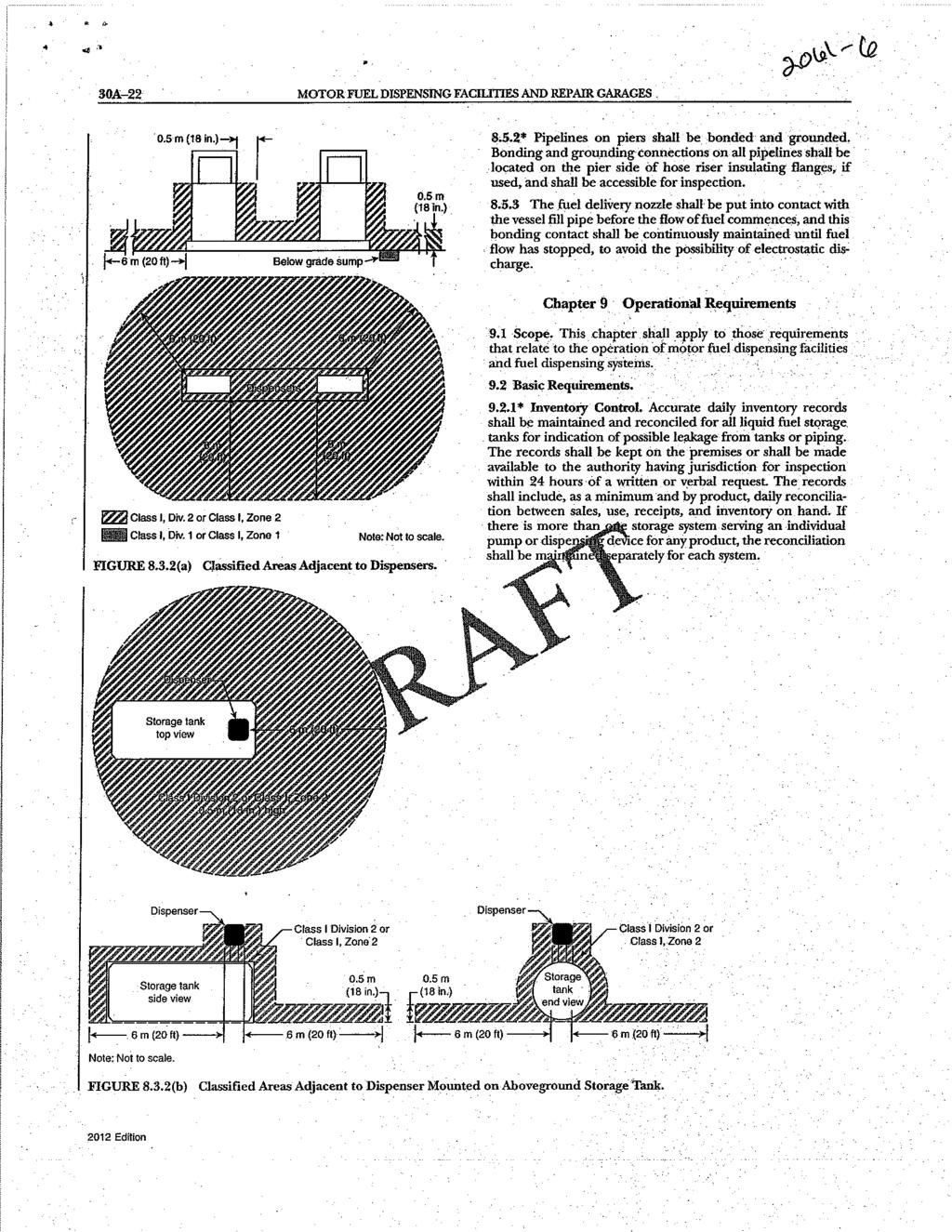
160
Report on Proposals June 2013 NFPA 70
 14-1 Log #1170m NEC-P14 Russell LeBlanc, The Peterson School In articles 90 through 830, if the wording is not already there, then add the words (or other structure(s)) after the word BUILDING(S) wherever
Report on Proposals June 2013 NFPA 70
 14-1 Log #1170m NEC-P14 Russell LeBlanc, The Peterson School In articles 90 through 830, if the wording is not already there, then add the words (or other structure(s)) after the word BUILDING(S) wherever
AGENDA. NEC Code-Making Panel 14. Report on Comment Meeting. November 28-December 1, Redondo Beach, CA
 National Fire Protection Association 1 Batterymarch Park, Quincy, MA 02169-7471 Phone: 617-770-3000 Fax: 617-770-0700 www.nfpa.org AGENDA NEC Code-Making Panel 14 Report on Comment Meeting November 28-December
National Fire Protection Association. 1 Batterymarch Park, Quincy, MA Phone: Fax:
 National Fire Protection Association 1 Batterymarch Park, Quincy, MA 02169-7471 Phone: 617-770-3000 Fax: 617-770-0700 www.nfpa.org M E M O R A N D U M TO: NEC Code-Making Panel 14 FROM: Kimberly Shea DATE:
MEMORANDUM. According to the final ballot results, all ballot items received the necessary affirmative votes to pass ballot.
 National Fire Protection Association 1 Batterymarch Park, Quincy, MA 02169-7471 Phone: 617-770-3000 Fax: 617-770-0700 www.nfpa.org MEMORANDUM To: NEC Code-Making Panel 14 From: Kimberly Shea, Project Administrator
ORDINANCE NO
 ORDINANCE NO. 2017-08-031 AN ORDINANCE OF THE CITY OF LANCASTER, TEXAS, REPEALING THE NATIONAL ELECTRICAL CODE 2014 EDITION IN ITS ENTIRETY AND REPLACING IT WITH THE ADOPTION OF THE NATIONAL ELECTRICAL
CODE DIGEST CODE DIGEST. Solutions.Worldwide.TM Crouse-Hinds is a registered trademark of Cooper Industries, Inc. COOPER CROUSE-HINDS
 COOPER CROUSE-HINDS COOPER CROUSE-HINDS CODE DIGEST CODE DIGEST Article 500-516 of the National Electrical Code with product recommendations for use in hazardous (classified) areas. Distributed by: For
ELECTRICAL SAFETY Information Bulletin
 ELECTRICAL SAFETY Information Bulletin February 2014 CEC-18 [rev-11] Page 1 of 9 CANADIAN ELECTRICAL CODE SUBJECT: Section 18 Hazardous Locations Rule 18-006 Division of Class I Locations General For classification
Overview of Hazardous Locations as They Relate to Solenoid Valves
 Overview of Hazardous Locations as They Relate to Solenoid Valves Defined: Hazardous Location - "where fire or explosion hazards may exist due to flammable gases or vapors, flammable liquids, combustible
Report on Proposals June 2010 NFPA 70
 16-1 Log #4917o NEC-P16 Caleb M. Ferris, Chadwick Electric Add a diagram table after the scope of each article similar to the one in Article 430. For NEC user cost make the table layout diagram in 430.8
NEC 2017 Changes and Their Effect Upon the ICT Industry
 NEC 2017 Changes and Their Effect Upon the ICT Industry Today s Presenters John Kacperski, RCDD, OSP, CDT Chair of BICSI Standards BICSI Representative on NFPA 70-CMP 16 Richard S. Anderson, RCDD, CDT,
Products Solutions Services CT287. Hazardous Area Classifications and Protection Systems
 Products Solutions Services CT287 Hazardous Area Classifications and Protection Systems Slide 1 Topics covered Types of Hazardous Area classifications with focus on North America Types of hazardous protection
HAZARDOUS AREA CLASSIFICATION AND SELECTION OF EQUIPMENT FOR SAFE USE THEREIN FROM AN ELECTRICAL VIEWPOINT
 HAZARDOUS AREA CLASSIFICATION AND SELECTION OF EQUIPMENT FOR SAFE USE THEREIN FROM AN ELECTRICAL VIEWPOINT Olof Bekker Pr. Eng. BSc. Eng. BML S.MSAIEE, M.NACE Engineering Manager, Electrical COMMITMENT
August Process Industry Practices Electrical. PIP ELEHA01 Engineering Guide for Determining Electrical Area Classification
 Electrical Engineering Guide for Determining Electrical Area Classification PURPOSE AND USE OF PROCESS INDUSTRY PRACTICES In an effort to minimize the cost of process industry facilities, this Practice
ELECTRICAL SAFETY Information Bulletin
 ELECTRICAL SAFETY Information Bulletin June 2018 CEC-18 [rev-13] Page 1 of 6 CANADIAN ELECTRICAL CODE SUBJECT: Section 18 Hazardous locations Rule 18-006 Locations containing an explosive gas atmosphere
TABLE OF CONTENTS CHAPTER 1 GENERAL RULES CHAPTER 2 WIRING AND PROTECTION... 51
 TABLE OF CONTENTS About This Textbook...xi How to Use the National Electrical Code... 1 Article 90 Introduction to the National Electrical Code... 7 90.1 Purpose of the NEC... 7 90.2 Scope of the NEC...
Chapter 1 General... 5
 About This Textbook...xi About the National Electrical Code...xv About the Authors and Illustrator...xix About the Team...xxi Article 90 Introduction to the National Electrical Code... 1 90.1 Purpose of
ELECTRICAL SAFETY Information Bulletin
 ELECTRICAL SAFETY Information Bulletin October 2007 Page 1 of 11 CANADIAN ELECTRICAL CODE SUBJECT: Section 18 Hazardous Locations Rule 18-006 Division of Class I Locations General For classification requirements
PIP ELEHA01 Engineering Guide for Determining Electrical Area Classification
 September 2016 Electrical PIP ELEHA01 Engineering Guide for Determining Electrical Area Classification PURPOSE AND USE OF PROCESS INDUSTRY PRACTICES In an effort to minimize the cost of process industry
IDENTIFYING TRAY CABLES FOR YOUR NEXT INSTALLATION A WHITE PAPER
 IDENTIFYING TRAY CABLES FOR YOUR NEXT INSTALLATION A WHITE PAPER Published 3/23/2012 T hough rapidly increasing in popularity, tray cables are still a point of confusion for many. While the term tray cable
Electrical Area Classification 101 An Introduction to Area Classification the Basics IEEE Houston CED
 Electrical Area Classification 101 An Introduction to Area Classification the Basics IEEE Houston CED October 3rd, 2017 Vincent W. Wedelich, PE, MBA Project Manager Associate Electrical Engineer 10 Years
Second Revision No. 601 NFPA [ Section No [Excluding
 Second Revision No. 601 NFPA 70 2015 [ Section No. 300.4 [Excluding any Sub Sections] ] Where subject to physical damage, conductors, raceways, and cables shall be protected. Informational Note: Minor
First Revision No. 1-NFPA [ Chapter 2 ]
![First Revision No. 1-NFPA [ Chapter 2 ]](/thumbs/71/65939713.jpg "First Revision No. 1-NFPA [ Chapter 2 ]") First Revision No. 1-NFPA 499-2014 [ Chapter 2 ] Chapter 2 Referenced Publications 2.1 General. The documents or portions thereof listed in this chapter are referenced within this recommended practice
First Revision No. 1-NFPA 499-2014 [ Chapter 2 ] Chapter 2 Referenced Publications 2.1 General. The documents or portions thereof listed in this chapter are referenced within this recommended practice
Cable Connectors For Armored Cable, Flexible Metal Conduit, Interlocked AC-38 Cables, NM and SE Cable
 For Armored Cable, Flexible Metal Conduit, Interlocked AC-38 Cables, NM and SE Cable To ground and secure Armored Cable, Flexible Metal Conduit and Interlocked Metal Clad Cables to boxes and enclosures.
Introduction to Hazardous Electrical Location Classifications
 Introduction to Hazardous Electrical Location Classifications Introduction In North America the target audience for this white paper and the electrical code classification ratings for various types of
Continuing Education, For UDC Electrical Inspectors, Commercial Electrical Inspectors, Master Electricians and Journeyman Electricians.
 Continuing Education, For UDC Electrical Inspectors, Commercial Electrical Inspectors, Master Electricians and Journeyman Electricians. The following test is for Continuing Education Credits for the abovementioned
Company, Inc. Location
 Electrical Company, Inc. Location Electrical Compliance Audit December 04, 2007 Solutions Corp. Electrical Solutions Corporation 2368 Eastman Ave, Suite 13, Ventura CA 93003 Greetings, On December 4, 2007,
Public Input No. 52-NFPA [ Section No [Excluding any Sub-Sections] ]
![Public Input No. 52-NFPA [ Section No [Excluding any Sub-Sections] ]](/thumbs/81/83983503.jpg "Public Input No. 52-NFPA [ Section No [Excluding any Sub-Sections] ]") 8 of 93 11/6/2015 7:41 AM Public Input No. 52-NFPA 30-2015 [ Section No. 21.2 [Excluding any Sub-Sections] ] For the purpose of this chapter, the term in this section shall have the definitions given.
8 of 93 11/6/2015 7:41 AM Public Input No. 52-NFPA 30-2015 [ Section No. 21.2 [Excluding any Sub-Sections] ] For the purpose of this chapter, the term in this section shall have the definitions given.
NATIONAL ELECTRICAL CODE (NEC) & NFPA 70E ARC FLASH ELECTRICAL SAFETY
 & NFPA 70E ARC FLASH ELECTRICAL SAFETY") A new twist on the National Electrical Code - a practical application workshop. If you sign up in this class, prepare to work! Day 1: Fundamentals of OSHA requirements for performing electrical work -
A new twist on the National Electrical Code - a practical application workshop. If you sign up in this class, prepare to work! Day 1: Fundamentals of OSHA requirements for performing electrical work -
Fee $15 Course: NEC Changes 5 This course is valid for these credentials: Credential Description Cred Code Credit Hours
 www.garyklinka.com Page 1 of 9 Instructions: Fee $15 1. Print these pages. 2. Circle the correct answers and transfer them to the answer sheet. 3. Page down to the last page for the verification forms
Approval Standard for Electrical Equipment for Use in Hazardous (Classified) Locations - General Requirements
 Locations - General Requirements") Approval Standard for Electrical Equipment for Use in Hazardous (Classified) Locations - General Requirements Class Number 3600 December 2011 2011 FM Approvals LLC. All rights reserved. Foreword The FM
Approval Standard for Electrical Equipment for Use in Hazardous (Classified) Locations - General Requirements Class Number 3600 December 2011 2011 FM Approvals LLC. All rights reserved. Foreword The FM
Desiccant. Breather Range
 Desiccant 127 Breather Range 128 HBP & HB Types Transformer Breather Units & Accessories Desiccant Breather Range Why Choose Hawke? When specifying products used in critical electrical supply applications
ARTICLE 25. FUEL GAS CODE
 ARTICLE 25. Rule 1. Indiana Fuel Gas Code, 2003 Edition (Repealed) (Repealed by Fire Prevention and Building Safety Commission; filed Mar 18, 2008, 2:32 p.m.: 20080423-IR-675070479FRA, eff 90 days after
UL Topic III. Converting European EEx Certificates. Into. North American Division Certificates
 Note: While this material was originally prepared for presentation in February 1999, it has been updated to reflect the evolving technical requirements now applicable as of April 2003. UL Topic III Converting
Above Ground Fuel Tank Requirements
 FIRE DEPARTMENT in cooperation with Above Ground Fuel Tank Requirements The purpose of this document is to provide information about general Fire Code requirements for above ground storage within the unincorporated
Portable Equipment. Equipment with electrical components suitable to be moved by a single person without mechanical aids.
 Portable Equipment. Equipment with electrical components suitable to be moved by a single person without mechanical aids. Power Outlet. An enclosed assembly that may include receptacles, circuit breakers,
Articles , & National Electrical Code Review & Application Guide
 Articles 500-506, 510-511 & 513-516 2011 National Electrical Code Review & Application Guide Established in 1913, Killark has become a global provider of harsh and hazardous location equipment. The Killark
GASEOUS HYDROGEN SYSTEMS
 CHAPTER 7 GASEOUS HYDROGEN SYSTEMS SECTION 701 GENERAL 701.1 Scope. The installation of gaseous hydrogen systems shall comply with this chapter and Chapters 30 and 35 of the Fire Compressed gases shall
Not For General Distribution. For Committee Ballot 4053 Use Only. Draft 6: 10/07/2016
 This document is not an API Standard; it is under consideration within an API technical committee but has not Draft 6: 10/07/2016 Recommended Practice for Design, Installation, and Maintenance of Electrical
SECTION 2 NEC REFERENCES SECTION 1 LOW-VOLTAGE AND POWER- LIMITED SYSTEMS...1. CHAPTER 1 GENERAL Introduction...35
 SECTION 1 LOW-VOLTAGE AND POWER- LIMITED SYSTEMS...1 Overview of Low-Voltage and Power-Limited Systems...3 Chapter 4 Equipment for General Use...3 Chapter 5 Special Occupancies...3 Chapter 6 Special Equipment...4
NFPA 33 Standard for Spray Applica4on Using Flammable or Combus4ble Materials
 NFPA 33 Standard for Spray Applica4on Using Flammable or Combus4ble Materials Fire Preven4on Officers Associa4on of Bri4sh Columbia 2013 Annual Seminar Kelowna, Bri4sh Columbia May 9, 2013 NFPA 33 Scope
Approval Standard for Electric Equipment for use in Hazardous (Classified) Locations General Requirements
 Locations General Requirements") Approval Standard for Electric Equipment for use in Hazardous (Classified) Locations General Requirements Class Number 3600 November 1998 2002 FM Approvals LLC. All rights reserved. Foreword FM Approvals
Approval Standard for Electric Equipment for use in Hazardous (Classified) Locations General Requirements Class Number 3600 November 1998 2002 FM Approvals LLC. All rights reserved. Foreword FM Approvals
National Fire Protection Association. 1 Batterymarch Park, Quincy, MA Phone: Fax:
 National Fire Protection Association 1 Batterymarch Park, Quincy, MA 02169-7471 Phone: 617-770-3000 Fax: 617-770-0700 www.nfpa.org M E M O R A N D U M TO: FROM: NFPA Technical Committee on Hot Work Operations
Smoke detection in hazardous areas:
 WHITE PAPER Smoke detection in hazardous areas: What you need to know Smoke detection in hazardous areas requires detectors that operate effectively and safely in explosive environments. Having the correct
REGULATIONS EUROPEAN ATEX DIRECTIVE. INTERNATIONAL SCHEME: IECEx AREAS CLASSIFICATION DEFINED BY DIRECTIVE 1999/92/EC
 EUROPEAN ATEX DIRECTIVE > European Directive 2014/34/EU ATEX Directive 2014/34/EU is a "new approach" directive that applies to protective systems against explosions as well as all equipment used in or
Michigan Chapter IAEI Annual Meeting Ann Arbor, Michigan Code Panel Questions December 5 th and 6 th, 2013
 Michigan Chapter IAEI Annual Meeting Ann Arbor, Michigan Code Panel Questions December 5 th and 6 th, 2013 1. Is a standard wire-nut approved for a wet location as in an outside j-box? Is there a listed
This is intended to provide uniform application of the codes by the plan check staff and to help the public apply the codes correctly.
 SUPPLEMENTAL CORRECTION SHEET FOR METHANE MITIGATION SYSTEMS - ELECTRICAL This is intended to provide uniform application of the codes by the plan check staff and to help the public apply the codes correctly.
NFPA Technical Committee on Fire Tests FALL 2011 ROC MEETING MINUTES
 National Fire Protection Association 1 Batterymarch Park, Quincy, MA 02169-7471 Phone: 617-770-3000 Fax: 617-770-0700 www.nfpa.org NFPA Technical Committee on Fire Tests FALL 2011 ROC MEETING MINUTES 1.
Get it Right the First Time Avoid These Commonly Cited Errors
 May 2014 Get it Right the First Time Avoid These Commonly Cited Errors By Mark Earley and Mark Hilbert Copyright 2014 National Fire Protection Association. All rights reserved. Good electrical contractors
Selecting a Safe Tank Gauging Product. Understanding Hazardous Area Definitions for Equipment Approvals
 Selecting a Safe Tank Gauging Product Understanding Hazardous Area Definitions for Equipment Approvals Hazardous Area Approvals A Worldwide Requirement There are many environmental considerations within
Part I Extraction Process Equipment
 745 West Colfax Avenue Denver, CO 80204 p: 720.913.3474 f: 720.913.3596 www.denvergov.org/fire MARIJUANA EXTRACTION GUIDELINE FOR COMMERCIAL / LICENSED FACILITIES The information contained within this
TRI-SERVICE ELECTRICAL WORKING GROUP (TSEWG) 07/16/08 TSEWG TP-8: ELECTRICAL EQUIPMENT ENCLOSURES AND HAZARDOUS LOCATIONS
 07/16/08 TSEWG TP-8: ELECTRICAL EQUIPMENT ENCLOSURES AND HAZARDOUS LOCATIONS") TSEWG TP-8: ELECTRICAL EQUIPMENT ENCLOSURES AND HAZARDOUS LOCATIONS ENCLOSURES. Select equipment enclosures to provide the following: To protect facility personnel from coming in contact with live parts.
TSEWG TP-8: ELECTRICAL EQUIPMENT ENCLOSURES AND HAZARDOUS LOCATIONS ENCLOSURES. Select equipment enclosures to provide the following: To protect facility personnel from coming in contact with live parts.
Drive Technology \ Drive Automation \ System Integration \ Services * _0817* Inquiry Forms for Explosion-Proof Gearmotors
 Drive Technology \ Drive Automation \ System Integration \ Services *23511257_0817* Inquiry Forms for Explosion-Proof Gearmotors Edition 08/2017 23511257/EN SEW-EURODRIVE Driving the world Inquiry forms
MODULAR INTEGRATION OF PROCESS EQUIPMENT PACKAGES FOR OIL AND GAS FACILITIES
 MODULAR INTEGRATION OF PROCESS EQUIPMENT PACKAGES FOR OIL AND GAS FACILITIES Copyright Material PCIC Europe Paper No. PCIC Europe LO-70 Allan Bozek EngWorks, Inc. 1620 49 th Avenue, SW Calgary, AB T2T
MEMORANDUM. NFPA Technical Committee on Solvent Extraction Plants. NFPA 36 First Draft TC FINAL Ballot Results (F2016)
") National Fire Protection Association 1 Batterymarch Park, Quincy, MA 02169-7471 Phone: 617-770-3000 Fax: 617-770-0700 www.nfpa.org MEMORANDUM To: From: NFPA Technical Committee on Solvent Extraction Plants
National Fire Protection Association 1 Batterymarch Park, Quincy, MA 02169-7471 Phone: 617-770-3000 Fax: 617-770-0700 www.nfpa.org MEMORANDUM To: From: NFPA Technical Committee on Solvent Extraction Plants
National Fire Protection Association. 1 Batterymarch Park, Quincy, MA Phone: Fax:
 National Fire Protection Association 1 Batterymarch Park, Quincy, MA 02169-7471 Phone: 617-770-3000 Fax: 617-770-0700 www.nfpa.org M E M O R A N D U M TO: NEC Code-Making Panel 3 FROM: Kimberly Shea DATE:
ELECTRIC and NEON SIGN STANDARDS. By Randy Wright RKW CONSULTING
 SEMINAR 301 Part 1: Changes in the 2005 NEC SEMINAR RULES: There are no Rules All Questions need to be asked Stop at any time for an explanation SEMINAR PARTS: ELECTRIC and NEON SIGN STANDARDS By Randy
SERIES & NO. SMI SUBJECT: SAFE CONSIDERATIONS FOR AN APPLICATION OF SPECIAL ELECTRICAL SYSTEMS
 1 of 4 SUBJECT: SAFE CONSIDERATIONS FOR AN APPLICATION OF I. PURPOSE To provide basic guidelines for identifying electrical systems required for special installations. II. REFERENCES National Electric
Certificate of Compliance
 FF0 001 Certificate of Compliance Certificate: 70116284 (LR 064969_0_00) Issued to: Mine Safety Appliances Company North American Division 1000 Cranberry Woods Dr Cranberry Township, Pennsylvania 16066-5296
 Page 1 of 19 Committee Input No. 14-NFPA 33-2013 [ Global Input ] Type your content here... Supplemental Information File Name IndoorDraftforCI.docx Description This committee input would be added to new
INSTALLATION, OPERATING & MAINTENANCE INSTRUCTIONS FOR 350 SERIES CIRCULATION HEATERS
 INDEECO Circulation Heaters are designed to provide years of trouble free operation if properly installed and maintained. Please read and follow these instructions for installing and maintaining the heater.
Today's world of increasing
 Applying Intrinsic Safety Today's world of increasing process control in potentially explosive atmospheres has forced designers and engineers to specify more efficient and effective ways of protecting
Committee on NFPA 51A
 Committee on M E M O R A N D U M TO: FROM: NFPA Technical Committee on Industrial and Medical Gases Patti Mucci, Administrative Assistant DATE: May 6, 2010 SUBJECT: ROC Letter Ballot The ROC letter ballot
UL HAZARDOUS LOCATIONS SERVICES
 UL HAZARDOUS LOCATIONS SERVICES The international preference in hazardous locations certification for over 100 years ul.com/hazloc Explosive Gas Atmospheres Class I Division S Includes flammable gases,
Fire Alarm System Accessories
 UL, ULC Approved* Fire Alarm System Accessories Intrinsically Safe Devices Single and Dual Channel Isolated Barrier Modules Features Single or dual channel intrinsically safe, transformer isolated barrier
Fire Department HEADQUARTERS Cathedral Oaks Road Santa Barbara, CA (805) FAX: (805) CODE SUMMARY
 FAX: (805) CODE SUMMARY") Fire Department HEADQUARTERS 4410 Cathedral Oaks Road Santa Barbara, CA 93110-1042 (805) 681-5500 FAX: (805) 681-5563 Michael W. Dyer Fire Chief County Fire Warden Eric Peterson Deputy Fire Chief CODE
Fire Department HEADQUARTERS 4410 Cathedral Oaks Road Santa Barbara, CA 93110-1042 (805) 681-5500 FAX: (805) 681-5563 Michael W. Dyer Fire Chief County Fire Warden Eric Peterson Deputy Fire Chief CODE
First Revision No. 49-NFPA 17A-2015 [ Detail ] Submitter Information Verification. Committee Statement 7/30/2015 1:35 PM
![First Revision No. 49-NFPA 17A-2015 [ Detail ] Submitter Information Verification. Committee Statement 7/30/2015 1:35 PM](/thumbs/85/92270546.jpg "First Revision No. 49-NFPA 17A-2015 [ Detail ] Submitter Information Verification. Committee Statement 7/30/2015 1:35 PM") of 25 7/30/2015 1:35 PM First Revision No. 49-NFPA 17A-2015 [ Detail ] Make the following change to 5.2.1.10.2: 5.2.1.10.2* The manual actuation device shall clearly identify the hazard protected and provide
of 25 7/30/2015 1:35 PM First Revision No. 49-NFPA 17A-2015 [ Detail ] Make the following change to 5.2.1.10.2: 5.2.1.10.2* The manual actuation device shall clearly identify the hazard protected and provide
Certificate of Compliance
 FF0 001 Certificate of Compliance Certificate: 70116279 (LR 025993_0_000) Issued to: General Monitors, Incorporated 26776 Simpatica Circle Lake Forest, California 92630 USA Attention: Larry Vlagea The
Hazardous Area Classification in Oil & Gas Industry. A Fire Prevention Tool
 Hazardous Area Classification in Oil & Gas Industry A Fire Prevention Tool SFPE ENGINEERING TECHNOLOGY CONFERENCE Oct 4, 2010 New Orleans, LA 1 Overview Oil and gas plants handle flammable materials 2
Public Input No. 1-NFPA [ Global Input ] Statement of Problem and Substantiation for Public Input. Related Public Inputs for This Document
![Public Input No. 1-NFPA [ Global Input ] Statement of Problem and Substantiation for Public Input. Related Public Inputs for This Document](/thumbs/96/127344595.jpg "Public Input No. 1-NFPA [ Global Input ] Statement of Problem and Substantiation for Public Input. Related Public Inputs for This Document") of 79 1/27/2016 2:09 PM Public Input No. 1-NFPA 59-2015 [ Global Input ] Throughout standard remove references to the following and replace with the following: (1) ANSI/API and replace with API. (2) ANSI/UL
of 79 1/27/2016 2:09 PM Public Input No. 1-NFPA 59-2015 [ Global Input ] Throughout standard remove references to the following and replace with the following: (1) ANSI/API and replace with API. (2) ANSI/UL
An Urgent Bulletin from CSA Group
 An Urgent Bulletin from CSA Group Hazardous Locations Products No. 28 (Supersedes Electrical Certification Notice No. 544A) Date: January 3, 2018 See Attachment 1 for Effective Dates. See Attachment 1
Installation guide for hazardous areas
 Installation guide for hazardous areas This installation guide should not be used as the controlling document for the installation of devices in a hazardous area. This guide is NOT A CONTROL DRAWING. Any
Committee on NFPA 85
 Committee on NFPA 85 M E M O R A N D U M TO: FROM: NFPA Technical Committee on Single Burner Boilers Patti Mucci, Technical Assistant II DATE: August 5, 2009 SUBJECT: NFPA ROP Letter Ballot The ROP letter
Electrical Tech Note 107
 Electrical Tech Note 107 Biosystems & Agricultural Engineering Department Michigan State University Understanding the Construction Code Rules, Part 8 1 Based on the 2014 NEC and the 2015 MRC The State
Understanding Hazardous Locations Concepts
 Gas Well Deliquification Workshop Sheraton Hotel, February 23 26, 2014 Understanding Hazardous Locations Concepts Mark Scantlebury, P. Eng., BASc President and CEO Extreme Telematics Corp. Disclaimer The
A Guide to Safe Electronic Weighing in Hazardous Locations
 SMART SOLUTIONS FOR DEMANDING INDUSTRIES Solutions for Process Weighing and Force Measurement Handbook TC0013 1. Hazardous Locations... 2 2. Methods of Protection... 3 3. Approval/Listing of Equipment...
DuPont Formacel Z-2. Safety and Handling of DuPont Formacel Z-2: Thermoplastic* Foam Extrusion Applications FOAM EXPANSION AGENT TECHNICAL INFORMATION
 DuPont Formacel Z-2 FOAM EXPANSION AGENT TECHNICAL INFORMATION Safety and Handling of DuPont Formacel Z-2: Thermoplastic* Foam Extrusion Applications Flammability of Formacel Z-2 and Other Alternative
J-PRO TM Cable Support System
 Frequently Asked Questions Cable Support System What references define how and where J-hooks are used? J-hooks are a horizontal pathway promoted in the BICSI TDM manual as a means to route small to medium
National Fire Protection Association. 1 Batterymarch Park, Quincy, MA Phone: Fax:
 National Fire Protection Association 1 Batterymarch Park, Quincy, MA 02169-7471 Phone: 617-770-3000 Fax: 617-770-0700 www.nfpa.org M E M O R A N D U M TO: FROM: NFPA Technical Committee on Merchant Vessels
Executive Summary. Shell Offshore Inc. BY: Keith M. Gonzales Sr., P.E. Regulatory Requirements for Hazardous Locations
 Contents Executive Summary... 1 Regulatory Requirements in the Gulf of Mexico for Hazardous Locations... 2 Referenced Codes and Standards... 2 Memorandum of Agreement... 2 Bureau of Ocean Energy Management
Public Input No. 4-NFPA [ Section No ] Statement of Problem and Substantiation for Public Input. Submitter Information Verification
![Public Input No. 4-NFPA [ Section No ] Statement of Problem and Substantiation for Public Input. Submitter Information Verification](/thumbs/82/85532729.jpg "Public Input No. 4-NFPA [ Section No ] Statement of Problem and Substantiation for Public Input. Submitter Information Verification") Public Input No. 4-NFPA 496-2014 [ Section No. 5.2.2 ] 5.2.2 Where When the enclosure has been opened or if the protective gas supply has failed to maintain the required positive pressure, the enclosure
Public Input No. 4-NFPA 496-2014 [ Section No. 5.2.2 ] 5.2.2 Where When the enclosure has been opened or if the protective gas supply has failed to maintain the required positive pressure, the enclosure
Numerical Standards Listing
 Numerical Standards Listing ISA-RP2.1-1978 - Manometer Tables ISA-5.1-1984 (R1992) - Instrumentation Symbols and Identification (Formerly ANSI/ISA-5.1-1984 [R1992]) ISA-5.2-1976 (R1992) - Binary Logic
Electrical Safety Requirements
 Electrical Safety Requirements Purpose This document defines the minimum required control measures to reduce the risk of injury or illness related to electricity. Scope Applicable to all Coca-Cola system
Report on First Revisions with Statement June 2014 NFPA 101
 101 FR7040 SAF-MER (36.1.1.4) 36.1.1.4 The provisions of this chapter shall apply to life safety requirements for all new mercantile buildings. Specific requirements shall apply to suboccupancy groups,
CHAPTER 15 PART IV NATIONAL ELECTRICAL CODE, 2017
 CHAPTER 15 PART IV NATIONAL ELECTRICAL CODE, 2017 The City of Portsmouth adopts the State Building Code, which adopts by reference The National Electrical Code, 2017(NEC), as Chapter 15, Part IV, of the
Report on Proposals F2007 Copyright, NFPA NFPA 499 Report of the Committee on
 Report on Proposals F2007 Copyright, NFPA NFPA 499 Report of the Committee on This list represents the membership at the time the Committee was balloted on the text of this edition. Since that time, changes
Copy Right By: Thomas T.S. Wan
 Chapter 23 Motor and Starter Copy Right By: Thomas T.S. Wan 温到祥著 Sept. 3, 2008 All rights reserved Electric Motors All the motors are to be designed and constructed in accordance with NEMA code. Electric
Understanding. Combustible Dust Hazards: Basic Measures to Ensure the Safety of Combustible Dust Handling Operations
 Understanding Combustible Dust Hazards: Basic Measures to Ensure the Safety of Combustible Dust Handling Operations Michigan Safety Conference April 11, 2017 Mike Snyder PE CSP CFPS Vice President Organizational
AGENDA. NEC Code-Making Panel 12. Report on Comment Meeting. Dates: November 28 December 1, Redondo Beach, CA
 National Fire Protection Association 1 Batterymarch Park, Quincy, MA 02169-7471 Phone: 617-770-3000 Fax: 617-770-0700 www.nfpa.org AGENDA NEC Code-Making Panel 12 Report on Comment Meeting Dates: November
First Revision No. 3-NFPA 51B-2016 [ New Section after 1.5 ] Submitter Information Verification. Committee Statement 11/18/2016 2:25 PM
![First Revision No. 3-NFPA 51B-2016 [ New Section after 1.5 ] Submitter Information Verification. Committee Statement 11/18/2016 2:25 PM](/thumbs/93/114174898.jpg "First Revision No. 3-NFPA 51B-2016 [ New Section after 1.5 ] Submitter Information Verification. Committee Statement 11/18/2016 2:25 PM") of 28 11/18/2016 2:25 PM First Revision No. 3-NFPA 51B-2016 [ New Section after 1.5 ] 1.6 Units and Formulas. 1.6.1 The units of measure in this standard are presented first in U.S. customary units (inch-pound
of 28 11/18/2016 2:25 PM First Revision No. 3-NFPA 51B-2016 [ New Section after 1.5 ] 1.6 Units and Formulas. 1.6.1 The units of measure in this standard are presented first in U.S. customary units (inch-pound
Beamex. Calibration White Paper. Calibration in hazardous areas
 Beamex Calibration White Paper info@beamex.com Calibration in hazardous areas This article discusses calibration in hazardous areas and what everyone needs to be aware of before entering into a hazardous
CLASS I LOCATIONS ZONE CLASSIFICATION
 HAZARDOUS (CLASSIFIED) LOCATIONS Hazardous locations are those locations where the risk of a fire or explosion may exist due to the presence of flammable gases or vapors, flammable liquids, combustible
Overview of Significant 2017 NEC Changes
 Overview of Significant 2017 NEC Changes National Fire Protection Association. All rights reserved. Five New NEC Articles Article 426 Fixed Resistance and Electrode Industrial Heating Equipment Article
Public Input No. 1-NFPA 99B-2015 [ Section No. 2.3 ] Statement of Problem and Substantiation for Public Input. Related Public Inputs for This Document
![Public Input No. 1-NFPA 99B-2015 [ Section No. 2.3 ] Statement of Problem and Substantiation for Public Input. Related Public Inputs for This Document](/thumbs/72/66518590.jpg "Public Input No. 1-NFPA 99B-2015 [ Section No. 2.3 ] Statement of Problem and Substantiation for Public Input. Related Public Inputs for This Document") 1 of 19 10/21/2015 1:20 PM Public Input No. 1-NFPA 99B-2015 [ Section No. 2.3 ] 2.3 Other Publications. 2.3.1 ASME Publications. American Society of Mechanical Engineers, Three ASME International, Two
1 of 19 10/21/2015 1:20 PM Public Input No. 1-NFPA 99B-2015 [ Section No. 2.3 ] 2.3 Other Publications. 2.3.1 ASME Publications. American Society of Mechanical Engineers, Three ASME International, Two
Airo Wireless Intrinsically Safe White Paper. Written By: David Schmitt
 Airo Wireless Intrinsically Safe White Paper Written By: David Schmitt Intrinsically Safe Cell Phone/Smartphone/PDA Intrinsically Safe (IS) is a protection certification for safe operation with electronic
CONTROL BE MADE CHANGES MAY NOT. Page 1
 HI 6020IT and HI 6020JB US & Canada Hazardous Locations User Guide (Class I, II, III, Division 1, Class I, Zone 0 and Zone 20) Hardy Process Solutions Document Number: : 0596-0352-01 REV A CONTROL LLED
Beamex Calibration White Paper. Calibration in hazardous areas
 Beamex Calibration White Paper info@beamex.com Calibration in hazardous areas This article discusses calibration in hazardous areas and what everyone needs to be aware of before entering into a hazardous
CIR CRUSH & IMPACT RESISTANT OIL & GAS CABLES
 CIR CRUSH & IMPACT RESISTANT OIL & GAS CABLES Gexol CIR Crush and Impact Resistant Without External Armoring Passes the same stringent crush and impact testing required by UL 2225 for Type MC-HL Index
SECTION AUTOMATIC TRANSFER SWITCHES
 PART 1 - GENERAL 1.1 DESCRIPTION SECTION 26 36 23 SPEC WRITER NOTE: Use this section only for NCA projects. Delete between //--// if not applicable to project. Also, delete any other item or paragraph
ELECTRICAL - WIRING DESIGN AND PROTECTION SELF INSPECTION CHECKLIST
 Name of School: OPTIONAL INFORMATION Date of Inspection: Vocational Program/Course/Room: Signature of Inspector: ELECTRICAL - WIRING DESIGN AND PROTECTION SELF INSPECTION CHECKLIST Guidelines: This checklist