ONE BUTTON DOOR ENTRY KIT WITH CODED ACCESS VR120DK-1/CL TECHNICAL MANUAL EDITION 1.0
|
|
|
- Morris Green
- 5 years ago
- Views:
Transcription


1 ONE BUON DOOR ENRY KI WIH CODED ACCESS VR120DK-1/CL ECHNICAL MANUAL EDIION 1.0
2 Page 2
3 CONENS D ĂŶƵĂů /ŶƚƌŽĚƵĐƟ ŽŶ ^LJƐƚĞŵ /ŶƚƌŽĚƵĐƟ ŽŶ System Components 136 Amplifier VR4KCLM codelock Panel and Back Box Dimensions Power Supply (Art.520M) Audiophone (Art.3011) Accessories Art.512A Extension Sounder ES/1 Extension Strobe Art.506N relay /ŶƐƚĂůůĂƟ ŽŶ Cable ype and Cable Size Guide Block Diagram WĂŶĞů ĂŶĚ ĂĐŬ Ždž /ŶƐƚĂůůĂƟ ŽŶ Panel Care dğɛɵ ŶŐ ƚśğ /ŶƐƚĂůůĂƟ ŽŶ ĐĐĞƐƐŽƌŝĞƐ ŽŶŶĞĐƟ ŽŶ ' ƵŝĚĞ Codelock Programming Guide Wiring Diagrams ͻ ϭ ďƶʃ ŽŶ ĂƵĚŝŽ ƉĂŶĞů ǁ ŝƚś ĐŽĚĞůŽĐŬ ͻ ϭ ďƶʃ ŽŶ ĂƵĚŝŽ ƉĂŶĞů ǁ ŝƚś ϯ ĂƵĚŝŽƉŚŽŶĞƐ dƌžƶďůğ ^ŚŽŽƟ ŶŐ ' ƵŝĚĞ Notes PAGE Page 3


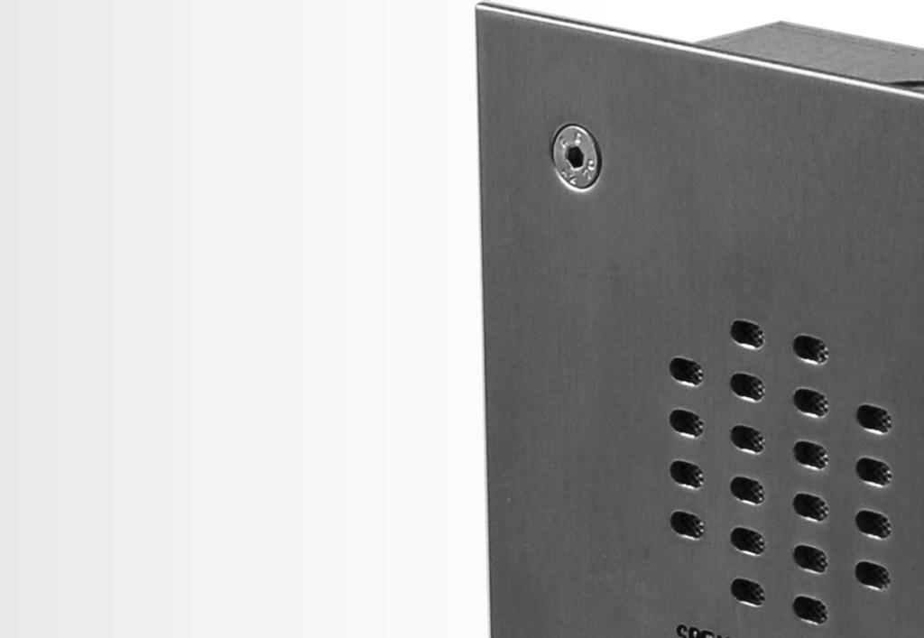
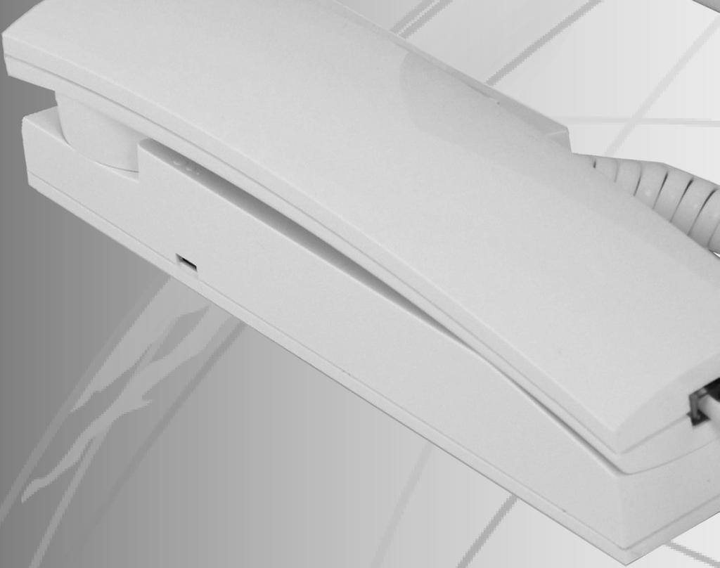
4 MANUAL INRODUCION ŚĞ ŝŷĩžƌŵăɵ ŽŶ ŝŷ ƚśŝɛ ŵăŷƶăů ŝɛ ŝŷƚğŷěğě ĂƐ ĂŶ ŝŷɛƚăůůăɵ ŽŶ ĂŶĚ ĐŽŵŵŝƐƐŝŽŶŝŶŐ ŐƵŝĚĞ ĨŽƌ ƚśğ s ŝěğdž s ZϭϮϬ ǀ ĂŶĚĂů ƌğɛŝɛƚăŷƚ ŽŶĞ ďƶʃ ŽŶ ĂƵĚŝŽ ŝŷƚğƌđžŵ Ŭŝƚ ǁ ŝƚś ŬĞLJƉĂĚ dśŝɛ ŵăŷƶăů ƐŚŽƵůĚ ďğ ƌğăě ĐĂƌĞĨƵůůLJ ďğĩžƌğ ƚśğ ŝŷɛƚăůůăɵ ŽŶ ĐŽŵŵĞŶĐĞƐ ŶLJ ĚĂŵĂŐĞ ĐĂƵƐĞĚ ƚž ƚśğ ĞƋƵŝƉŵĞŶƚ ĚƵĞ ƚž ĨĂƵůƚLJ ŝŷɛƚăůůăɵ ŽŶƐ ǁ ŚĞƌĞ ƚśğ ŝŷĩžƌŵăɵ ŽŶ ŝŷ ƚśŝɛ ŵăŷƶăů ŚĂƐ ŶŽƚ ďğğŷ ĨŽůůŽǁ ĞĚ ŝɛ ŶŽƚ ƚśğ ƌğɛɖžŷɛŝďŝůŝƚlj ŽĨ Videx Security Ltd. V IDEX run free training courses for engineers who have not installed this system before. echnical help is also available on during office hours or via tech@videx-security.com. A n electronic copy of this technical manual can be downloaded by scanning the QR code to the right. SYSEM INRODUCION his audio kit will enable a caller at an entrance point to signal an occupant in the dwelling by pressing Ă ĐĂůů ďƶʃ ŽŶ ǁ ŚŝĐŚ ǁ ŝůů ƐĞŶĚ ĂŶ ĞůĞĐƚƌŽŶŝĐ ĐĂůů ƚžŷğ ƚž ĂŶ ĂƵĚŝŽ ƚğůğɖśžŷğ zğůůžǁ ^W < > ǁ ŝůů ŝŷěŝđăƚğ ƚśğ ĐĂůů ŚĂƐ ďğğŷ ĂŶƐǁ ĞƌĞĚ ĂŶĚ Ă ƚǁ Ž ǁ ĂLJ ĐŽŶǀ ĞƌƐĂƟ ŽŶ ĐĂŶ ƚăŭğ ƉůĂĐĞ ƚśğ ŽĐĐƵƉĂŶƚ ĐĂŶ ƌğůğăɛğ ĂŶ ĞůĞĐƚƌŝĐ ůžđŭ ƌğůğăɛğ ďlj ƉƌĞƐƐŝŶŐ Ă ďƶʃ ŽŶ ŽŶ ƚśğ ƚğůğɖśžŷğ ďăɛğ ƵŶŝƚ dśğ Ŭŝƚ ĚŽĞƐ ŶŽƚ ŝŷđůƶěğ the electric lock release. A 12V AC release should be used with this kit (he output for the lock is a dry contact relay so any other type of lock can be used with an appropriate PSU). If this kit is to be used with a gate, the dry contact output can be used to trigger the gate control board. DDA features such as a SPEAK LED, BUSY LED, DOOR OPEN LED and reassurance tone are standard on this kit. A two code, two relay codelock unit is also incorporated into the door panel to allow users to gain access using an access code. A flush back box is standard in this kit, however a flush stainless steel bezel back box and a surface back box with rainshield are also available (see page 7). Key Features ͻ 12 Gauge stainless steel. /Wϲϴ ƌăƚğě ďƶʃ ŽŶ SPEAK, BUSY and OPEN call progress LEDs. Call progress reassurance tone. Dry contact relay output for lock release or gate controller. imed call, speech and lock release. Speaker and microphone volume adjustment. his audio kit can be used for a single entrance system, however it can ďğ ĞdžƉĂŶĚĞĚ ƚž ŝŷđůƶěğ ŵƶůɵ ƉůĞ ĞŶƚƌĂŶĐĞ ƉĂŶĞůƐ Page 4


 Speech live")

5 SYSEM COMPONENS ŚŝƐ Ŭŝƚ ĐŽŵƉƌŝƐĞƐ ŽĨ Ă Ň ƵƐŚ Žƌ ƐƵƌĨĂĐĞ ǀ ĂŶĚĂů ƌğɛŝɛƚăŷƚ ϭ ďƶʃ ŽŶ ĚŽŽƌ ƉĂŶĞů ŝŷđůƶěŝŷő Ă ĐŽĚĞůŽĐŬ power supply and audio telephone. Up to a maximum of three audio telephones can be used on this system to call in parallel. DOOR PANEL An audio or video vandal resistant door panel will consist ŽĨ Ă ϭϯ ϲ ĂŵƉůŝĮ Ğƌ ŵžěƶůğ ďƶʃ ŽŶ ĐŽŶŶĞĐƚŽƌ ďžăƌě ĂŶĚ Ŷ ŶƵŵďĞƌ ŽĨ ďƶʃ ŽŶƐ ĚĚŝƟ ŽŶĂůůLJ ĐĂůů ďƶʃ ŽŶƐ ĐĂŶ ďğ engraved to suite the apartment numbers. ^ƉĞĂŬĞƌ ŵžěƶůğ ĐŽŶŶĞĐƟ ŽŶƐ Ɛǁ ŝƚđśğɛ ĂŶĚ ũƶŵɖğƌ Dip-Switches dśğ ĨŽƵƌ ǁ ĂLJ ĚŝƉͲƐǁ ŝƚđś ďăŷŭ ŚĂƐ ƚśğ ĨŽůůŽǁ ŝŷő ĨƵŶĐƟ ŽŶƐ Please note: dip-switches must be set before power up. Any ĐŚĂŶŐĞƐ ŵăěğ ǁ ŚĞŶ ƉŽǁ Ğƌ ŝɛ ŽŶ ǁ ŝůů ŶŽƚ ƚăŭğ Ğī ĞĐƚ ƵŶƟ ů Ă power down reset. Speech ime Switch 1 OFF 1 minute Switch 1 ON 2 mintues Relay ime Speech Live Switch 2 OFF Switch 3 OFF 2 seconds Switch 2 ON Switch 3 OFF 8 seconds Switch 2 OFF Switch 3 ON Switch 2 ON 4 seconds Switch 3 ON 20 seconds Switch 4 OFF Only when called Switch 4 ON (only possible on one door systems) Speech live whenever ŚĂŶĚƐĞƚ ůŝō ĞĚ Jumper Jumper JP controls the reassurance tone volume level at the door panel. WŽƐŝƟ ŽŶ, WŽƐŝƟ ŽŶ > No Jumper High volume reassurance tone Low volume reassurance tone No reassurance tone POS Speech volume adjustments are carried out at the door panel using a small trimmer driver. adjustment for speech volume at the apartment (microphone) adjustment for speech volume level Ăƚ ƚśğ ĚŽŽƌ ƐƚĂƟ ŽŶ ƐƉĞĂŬĞƌͿ Page 5
 Live speech 108mA 5 Switched 0V from phone to trigger door release relay Lock Release 125mA ůğđƚƌžŷŝđ ĐĂůů ƚžŷğ ŽƵƚƉƵƚ ƚž ĐŽŵŵŽŶ ƐŝĚĞ ŽĨ ĐĂůů ďƶʃ ŽŶƐ Maximum 130mA - 0V for")
 LED. Not used with this kit D- External link to door open (0V side) LED.")
 F1 Switched 0V output to switch on camera. (0V throughout a call, open collector in standby) CODELOCK (Art.")
6 s yϭϯ ϲ ŵɖůŝį Ğƌ D ŽĚƵůĞ ŽŶŶĞĐƟ ŽŶ s yϭϯ ϲ ƵƌƌĞŶƚ ZĂƟ ŶŐ ŽŶ нϭϯs ĚĐ &ƵŶĐƟ ŽŶ ŽŶĚŝƟ ŽŶ 1 Receive speech from apartment Standby 18mA 2 ransmit speech to apartment System busy 58mA + +12Vdc input During a call 122mA - 0V (Ground) Live speech 108mA 5 Switched 0V from phone to trigger door release relay Lock Release 125mA ůğđƚƌžŷŝđ ĐĂůů ƚžŷğ ŽƵƚƉƵƚ ƚž ĐŽŵŵŽŶ ƐŝĚĞ ŽĨ ĐĂůů ďƶʃ ŽŶƐ Maximum 130mA - 0V for use with push to exit input (PE) PE Current (ma) ^ǁ ŝƚđśğě Ϭs ŝŷɖƶƚ ĨƌŽŵ ƉƵƐŚ ƚž Ğdžŝƚ ďƶʃ ŽŶ ƚž ƚƌŝőőğƌ ĚŽŽƌ ƌğůğăɛğ ƌğůălj C ŽŵŵŽŶ ĐŽŶŶĞĐƟ ŽŶ ŽĨ ĚƌLJ ĐŽŶƚĂĐƚ ƌğůălj NC E ŽƌŵĂůůLJ ĐůŽƐĞĚ ĐŽŶŶĞĐƟ ŽŶ ŽĨ ĚƌLJ ĐŽŶƚĂĐƚ ƌğůălj NO E ŽƌŵĂůůLJ ŽƉĞŶ ĐŽŶŶĞĐƟ ŽŶ ŽĨ ĚƌLJ ĐŽŶƚĂĐƚ ƌğůălj D+ External link to door open (+12V side) LED. Not used with this kit D- External link to door open (0V side) LED. Not used with this kit BSY ƵƐLJ ƐŝŐŶĂů ĨŽƌ ƵƐĞ ǁ ŝƚś ŵƶůɵ ƉůĞ ĚŽŽƌ ƐLJƐƚĞŵƐ E ŽƌŵĂůůLJ ŚŝŐŚ ϭϯs >Žǁ ǁ ŚĞŶ ďƶɛlj Ϭs Ϳ SL Switched 0V output to switch on video PSU. (0V throughout a call, open collector in standby) F1 Switched 0V output to switch on camera. (0V throughout a call, open collector in standby) CODELOCK (Art.VR4KCLM) he codelock module can be powered from 12-24V AC or DC and includes two dry contact relay ŽƵƚƉƵƚƐ ĂŶĚ ƚǁ Ž Ɛǁ ŝƚđśğě Ϭs ƉƵƐŚ ƚž Ğdžŝƚ ďƶʃ ŽŶ ŝŷɖƶƚɛ ǁ ŚŝĐŚ ĐĂŶ ďğ ƵƐĞĚ ƚž ƚƌŝőőğƌ ƌğůălj ϭ Θ Ϯ K ŶĞ ĐŽĚĞ ƉĞƌ ƌğůălj ĐĂŶ ďğ ƉƌŽŐƌĂŵŵĞĚ ŝŷƚž ƚśğ ĚĞǀ ŝđğ ŽĚĞƐ ĐĂŶ ďğ ϰͳθ ĚŝŐŝƚƐ ůžŷő dśğ ƌğůălj Ɵ ŵğ ĐĂŶ be seconds or set for latching (00). When in latching mode, enter the code followed by ENER to latch and the code followed by CLEAR to unlatch. Code lock module (Art.VR4KCLM) ŽŶŶĞĐƟ ŽŶ &ƵŶĐƟ ŽŶ V AC or DC power input - 0V power input C1 ZĞůĂLJ ϭ ĐŽŵŵŽŶ ĐŽŶŶĞĐƟ ŽŶ NO1 ZĞůĂLJ ϭ ŶŽƌŵĂůůLJ ŽƉĞŶ ĐŽŶŶĞĐƟ ŽŶ NC1 ZĞůĂLJ ϭ ŶŽƌŵĂůůLJ ĐůŽƐĞĚ ĐŽŶŶĞĐƟ ŽŶ C2 ZĞůĂLJ Ϯ ĐŽŵŵŽŶ ĐŽŶŶĞĐƟ ŽŶ NO2 ZĞůĂLJ Ϯ ŶŽƌŵĂůůLJ ŽƉĞŶ ĐŽŶŶĞĐƟ ŽŶ NC2 ZĞůĂLJ Ϯ ŶŽƌŵĂůůLJ ĐůŽƐĞĚ ĐŽŶŶĞĐƟ ŽŶ SW1 Switched 0V input to trigger relay 1 SW2 Switched 0V input to trigger relay 2 s Zϰ< >D ƵƌƌĞŶƚ ZĂƟ ŶŐ ŽŶ н ŝŷɖƶƚ ŽŶĚŝƟ ŽŶ Current (ma) Standby 18mA Relay rigger 35mA Max 40mA Codelock programming can be found on pages Page 6
7 PANEL AND BACK BOX DIMENSIONS ŚĞƌĞ ĂƌĞ ƚśƌğğ s ZϭϮϬ ƉĂŶĞů ďăđŭ ďždž ŽƉƟ ŽŶƐ Ăǀ ĂŝůĂďůĞ Ă ƐƚĂŶĚĂƌĚ Ň ƵƐŚ ďăđŭ ďždž Ă Ň ƵƐŚ ďăđŭ ďždž with bezel and a surface back box with rainshield (see below). FLUSH (VRFB120x280) FRON PANEL FLUSH WIH BEZEL (VRBB120x280) SURFACE WIH RAINSHIELD (VRSB120x280) Page 7


 230V~ Fuse compartment D ĂŝŶƐ ŝŷ >ŝǀ Ğ ĐŽŶŶĞĐƟ ŽŶͿ 0V D ĂŝŶƐ ŝŷ E ĞƵƚƌĂů ĐŽŶŶĞĐƟ ŽŶͿ AUDIOPHONE Art.")

 4 Electronic call")


8 POWER SUPPLY Art.520M he standard power supply in this kit is the Art.520M. Outputs of 12Vdc (200mA max), 8Vdc (300mA max) and 13Vac (1A max) are available. he dc outputs are designed to power the amplifier module only and cannot be used to power other devices such as code locks, lock releases etc. hese items must be connected to the AC output of this power supply. erminal &ƵŶĐƟ ŽŶ Vdc output (200mA max.) + 8Vdc output (300mA max.) - 0V (Ground) ~ 13Vac (1A max.) 230V~ Fuse compartment D ĂŝŶƐ ŝŷ >ŝǀ Ğ ĐŽŶŶĞĐƟ ŽŶͿ 0V D ĂŝŶƐ ŝŷ E ĞƵƚƌĂů ĐŽŶŶĞĐƟ ŽŶͿ AUDIOPHONE Art.3011 Art.3011 he Art.3011 audiophone is a smart line electronic call tone phone ĂŶĚ ŝŷđůƶěğɛ Ă ůžđŭ ƌğůğăɛğ ƉƵƐŚ ďƶʃ ŽŶ ĂŶĚ Ă ϯ ůğǀ Ğů ĐĂůů ƚžŷğ ǀ ŽůƵŵĞ Ɛǁ ŝƚđś ĂŶĚ ƌğƌƶŝƌğɛ Ă ŵŝŷŝŵƶŵ ŽĨ ϱ ĐŽƌĞƐ ĨŽƌ ĐŽŶŶĞĐƟ ŽŶ erminal &ƵŶĐƟ ŽŶ 1 ransmit speech to the door panel 2 Receive speech from the door panel 3 0V (Ground) 4 Electronic call tone input 5 Lock trigger (Switched 0V) 6 Not used 3 level call tone switch Other audiophones that can be used with this kit are the Art.3111 ƐƉĂƌĞ ƐĞƌǀ ŝđğ ďƶʃ ŽŶͿand the Art.3112 ƐƉĂƌĞ ƐĞƌǀ ŝđğ ďƶʃ ŽŶ ĂŶĚ ŵƶƚğ switch). terminal ĐŽŶŶĞĐƟ ŽŶƐ ACCESSORIES Art.512A Art.512A he Art.512A is an extension sounder that can be wall mounted and will ring whenever the audiophone it is connected to rings. he 512A requires an electronic calltone input. ŽŶŶĞĐƟ ŽŶƐ erminal &ƵŶĐƟ ŽŶ ŽŶĚŝƟ ŽŶ 4 Calltone input During a call 100mA - 0V (GND) Max 105mA Page 8 ƵƌƌĞŶƚ ZĂƟ ŶŐ ŵ Ϳ


9 ES/1 Extension Strobe ŚĞ ^ ϭ ŝɛ Ă Ɵ ŵğě ƐƚƌŽďĞ ƵŶŝƚ ĨŽƌ ƚśğ ŚĂƌĚ ŽĨ ŚĞĂƌŝŶŐ Žƌ ĐĂŶ ďğ ƵƐĞĚ ŝŷ ŶŽŝƐLJ ĞŶǀ ŝƌžŷŵğŷƚɛ dśğ ƐƚƌŽďĞ ǁ ŝůů Ň ĂƐŚ ǁ ŚĞŶ Ă ĐĂůů ŝɛ ƌğđğŝǀ ĞĚ ĂŶĚ ǁ ŝůů ĐŽŶƟ ŶƵĞ Ň ĂƐŚŝŶŐ ĨŽƌ ĂŶ ĂĚũƵƐƚĂďůĞ Ɵ ŵğ ƉĞƌŝŽĚ Žƌ ƵŶƟ ů ƚśğ ƌğɛğƚ ďƶʃ ŽŶ ŝɛ ƉƌĞƐƐĞĚ /ƚ ƌğƌƶŝƌğɛ Ă ϭϯs ĂĐ Žƌ ĚĐ ƉŽǁ Ğƌ ŝŷɖƶƚ ĂŶĚ ƚśğ ĂĚũƵƐƚĂďůĞ Ɵ ŵğ ƉĞƌŝŽĚ ĐĂŶ ďğ ƐĞƚ ďğƚǁ ĞĞŶ Ϯ Ͳ ϭϭϭ ƐĞĐŽŶĚƐ ŽŶŶĞĐƟ ŽŶƐ erminal ES/1 &ƵŶĐƟ ŽŶ ŽŶĚŝƟ ŽŶ Power 12Vac or dc input Standby I/P нɖžɛŝɵ ǀ Ğ ƚƌŝőőğƌ During a call +O/P 12Vdc output Max GND 0V (ground) Reset Switched 0V reset NC E ŽƌŵĂůůLJ ĐůŽƐĞĚ ƌğůălj ĐŽŶŶĞĐƟ ŽŶ CO ŽŵŵŽŶ ƌğůălj ĐŽŶŶĞĐƟ ŽŶ NO E ŽƌŵĂůůLJ ŽƉĞŶ ƌğůălj ĐŽŶŶĞĐƟ ŽŶ ƵƌƌĞŶƚ ZĂƟ ŶŐ ŵ Ϳ 6.6mA mA 180mA Art.506N relay ŚĞ ƌƚ ϱϭϲe ƵŶŝǀ ĞƌƐĂů ďždž ĞĚ ϭϯ Ϯϰs ĂĐ ĚĐ ĚŽƵďůĞ ƉŽůĞ ƌğůălj ĐĂŶ ďğ ƵƐĞĚ ĨŽƌ ŵăŷlj ĨƵŶĐƟ ŽŶƐ /ƚɛ ĐŚĂŶŐĞŽǀ Ğƌ ƌğůălj ĐŽŶƚĂĐƚƐ ĂƌĞ ƌăƚğě Ăƚ ϮϰϬs ĂĐ ϱ /ƚ ĂůƐŽ ŝŷđůƶěğɛ ůžǁ ĐƵƌƌĞŶƚ ƚƌăŷɛŝɛƚžƌ Ɛǁ ŝƚđśğě ŝŷɖƶƚɛ нɖžɛŝɵ ǀ Ğ ĂŶĚ ͲŶĞŐĂƟ ǀ Ğ ƚƌŝőőğƌɛͿ dśğ ƌƚ ϱϭϲe ƌğůălj ĐĂŶ ĂůƐŽ ďğ ƵƐĞĚ ƚž Ɛǁ ŝƚđś Ă ǀ Žůƚ ĨƌĞĞ ĐŽŶƚĂĐƚ ƚž Ă ŐĂƚĞ Žƌ ďăƌƌŝğƌ ĐŽŶƚƌŽůůĞƌ and also used to drop power off to a fail safe mag lock. ŽŶŶĞĐƟ ŽŶƐ erminal &ƵŶĐƟ ŽŶ 1 24V ac or DC input 2 12V ac or DC input 3 0V switched input (link to GND when not using terminal 4) 4 ^ǁ ŝƚđśğě нɖžɛŝɵ ǀ Ğ ŝŷɖƶƚ 5 ' E Ϭs ƉŽǁ Ğƌ ǁ ŚĞŶ ƵƐŝŶŐ Ɛǁ ŝƚđśğě нɖžɛŝɵ ǀ Ğ ŝŷɖƶƚͿ CO1 ŽŵŵŽŶ ƌğůălj ϭ ĐŽŶŶĞĐƟ ŽŶ NO1 E ŽƌŵĂůůLJ ŽƉĞŶ ƌğůălj ϭ ĐŽŶŶĞĐƟ ŽŶ NC1 E ŽƌŵĂůůLJ ĐůŽƐĞĚ ƌğůălj ϭ ĐŽŶŶĞĐƟ ŽŶ CO2 ŽŵŵŽŶ ƌğůălj Ϯ ĐŽŶŶĞĐƟ ŽŶ NO2 E ŽƌŵĂůůLJ ŽƉĞŶ ƌğůălj Ϯ ĐŽŶŶĞĐƟ ŽŶ NC2 E ŽƌŵĂůůLJ ĐůŽƐĞĚ ƌğůălj Ϯ ĐŽŶŶĞĐƟ ŽŶ Max. current and voltage for each relay 230Vac Art.506N Page 9
10 /ŶŝƟ Ăů /ŶƐƚĂůůĂƟ ŽŶ ŚĞĐŬƐ INSALLAION he wiring diagrams towards the back of this manual should be followed carefully. Heavy duty conductors on wiring diagrams are shown heavily outlined in some instances where voltage drop is experienced then these wires should be doubled up. Check that all components are free from damage before installing (Do not proceed with the instalůăɵ ŽŶ ŝŷ ƚśğ Ğǀ ĞŶƚ ŽĨ ĚĂŵĂŐĞͿ Keep all packaging away from children. ͻ Ž ŶŽƚ ŽďƐƚƌƵĐƚ ƚśğ ǀ ĞŶƟ ůăɵ ŽŶ ŽƉĞŶŝŶŐƐ Žƌ ƐůŽƚƐ ŽŶ ĂŶLJ ŽĨ ƚśğ ĚĞǀ ŝđğɛ ͻ ůů ĐŽŶŶĞĐƟ ŽŶƐ ƚž ŵăŝŷɛ ǀ ŽůƚĂŐĞƐ ŵƶɛƚ ďğ ŵăěğ ƚž ƚśğ ĐƵƌƌĞŶƚ ŶĂƟ ŽŶĂů ƐƚĂŶĚĂƌĚƐ / t ŝƌŝŷő ƌğőƶͳ ůăɵ ŽŶƐͿ ͻ /ŶƐƚĂůů ĂŶ ĂƉƉƌŽƉƌŝĂƚĞ ĨƵƐĞĚ ƐƉƵƌ Žƌ ŝɛžůăɵ ŽŶ Ɛǁ ŝƚđś ƚž ŝɛžůăƚğ ƚśğ ŵăŝŷɛ Isolate the mains before carrying out any maintenance work on the system. All intercom and access control cables must be routed separately from the mains. >ŽĐŬ ZĞůĞĂƐĞ t ŝƌŝŷő ĂŶĚ ĂĐŬ D & WƌŽƚĞĐƟ ŽŶ W ŚĞŶ Į ƫ ŶŐ ĂŶ ĞůĞĐƚƌŝĐ ůžđŭ ƌğůğăɛğ ďăđŭ D & ƉƌŽƚĞĐƟ ŽŶ ǁ ŝůů ďğ ƌğƌƶŝƌğě /Ĩ Į ƫ ŶŐ ĂŶ ůžđŭ ƌğůğăɛğ ƚśğŷ Ă ϭϭϭŷ& ĐĞƌĂŵŝĐ ĚŝƐĐ ĐĂƉĂĐŝƚŽƌ ŵƶɛƚ ďğ Į Ʃ ĞĚ ĂĐƌŽƐƐ ƚśğ ƚğƌŵŝŷăůɛ ŽŶ ƚśğ ůžđŭ /Ĩ Į ƫ ŶŐ Ă ůžđŭ ƌğůğăɛğ ĨĂŝů ƐĞĐƵƌĞ Žƌ ĨĂŝů ƐĂĨĞͿ ƚśğŷ Ă ϭe ϰϭϭϯ ĚŝŽĚĞ ŵƶɛƚ ďğ Į Ʃ ĞĚ ĂĐƌŽƐƐ ƚśğ ƚğƌŵŝŷăůɛ ŽŶ ƚśğ ůžđŭ Cable ypes CABLE YPE AND CABLE SIZE GUIDE ŚĞ ĨŽůůŽǁ ŝŷő ĐĂďůĞ ƚljɖğɛ ĚĞƐĐƌŝďĞĚ ďğůžǁ ĂƌĞ ŵğăɛƶƌğě ŝŷ ŵŵϸ ĨŽƌ ƚśğ ĐƌŽƐƐ ƐĞĐƟ ŽŶĂů ĂƌĞĂ ^ Ϳ ĨŽƌ each conductor (core) within the cable bundle. he tables show the distances in metres between system components. All cable types are catagorised using the AWG (American Wire Gauge). Suitable cables for this system are a B type telephone cable CW1308 and a YY cable (other similar or ĞƋƵŝǀ ĂůĞŶƚ ĐĂďůĞƐ ĂƌĞ ĂůƐŽ ƐƵŝƚĂďůĞͿ t ŚĞŶ ƐĞůĞĐƟ ŶŐ Ă ƉĂƌƟ ĐƵůĂƌ ĐĂďůĞ ƚljɖğ ĐĂƌĞ ŵƶɛƚ ďğ ƚăŭğŷ ƚž ĞŶƐƵƌĞ that excessive voltage drop is avoided and the lowest possible resistance is achieved. Use the following cable types and the tables as a guide to ensure that the best possible performance is achieved. Page 10
11 CW1308 elephone cable (CSA 0.22mm² AWG 24 - Maximum Resistance 97.8 Ohm/km) CW1308 is an internal grade cable and is available in 3 pair, 4 pair, 6 pair, 10 pair, 12 pair, 15 pair, 20 pair and 25 pair. CW1308B elephone cable (CSA 0.22mm² AWG 24 - Maximum Resistance 97.8 Ohm/km) CW1308B is an internal or external grade cable (if used externally must be protected) and is available in 10 pair and 20 pair. CW1128 elephone cable (CSA 0.22mm² AWG 24 - Maximum Resistance 96 Ohm/km) CW1128 is an external grade poly-filled cable (if used externally must be protected) and is available in 2 pair, 5 pair, 10 pair and 20 pair. CW1128 / CW1198 elephone cable (CSA 0.5mm² AWG 20 - Maximum Resistance 91 Ohm/km) CW1128 / CW1198 is an external grade poly-filled armoured cable (for direct burial) and is available in 2 pair, 5 pair, 10 pair and 20 pair. CA5e (CSA 0.2mm² AWG 24 - DC loop resistance <0.188 Ohm/m, converts to 94 Ohm/km) CA5e is an internal grade cable and is available in 4 pair. Please note that if CA5e cable is going to be ƵƐĞĚ ƚśğŷ ƚśğ ĐŚĂƌĂĐƚĞƌŝƐƟ ĐƐ ĂďŽǀ Ğ ŵƶɛƚ ďğ ŵğƚ ďlj ŵğăɛƶƌŝŷő ƚśğ ƌğɛŝɛƚăŷđğ ŽĨ ƚśğ ĐĂďůĞ ĚŝƌĞĐƚůLJ Žƌ ďlj ĐŽŶƐƵůƟ ŶŐ ƚśğ ŵăŷƶĩăđƚƶƌğƌ Ɛ ĚĂƚĂƐŚĞĞƚ YY Control Cable (CSA 0.5mm² AWG 24 - Maximum Resistance 39 Ohm/km) (CSA 0.75mm² AWG 18 - Maximum Resistance 26 Ohm/km) (CSA 1.0mm² AWG 17 - Maximum Resistance 19.5 Ohm/km) (CSA 1.5mm² AWG 15 - Maximum Resistance 13.3 Ohm/km) (CSA 2.5mm² AWG 13 - Maximum Resistance 8 Ohm/km) YY control cable is an internal or external grade cable (if used externally must be protected) and is available in 4 Core, 7 Core, 12 Core & 18 Core. Each cable comes with numbered cores in white on a black sheath and also includes a green/yellow earth core. ŽŶŶĞĐƟ ŽŶƐ ĨƌŽŵ ĚŽŽƌ ƉĂŶĞů ƚž ƵĚŝŽƉŚŽŶĞ ŽŶŶĞĐƟ ŽŶ 50m 100m 200m 300m 400m Power 0.35mm² 0.5mm² 0.75mm² 1.0mm² 1.5mm² All others 0.25mm² 0.35mm² 0.5mm² 0.75mm² 1.0mm² D ĂdžŝŵƵŵ ĂĐĐĞƉƚĂďůĞ ƌğɛŝɛƚăŷđğ ĨŽƌ ƉŽǁ Ğƌ ƚğƌŵŝŷăů ĐŽŶŶĞĐƟ ŽŶƐ с ϱ K ŚŵƐ Žƌ ůğɛɛ ĨŽƌ Ăůů ŽƚŚĞƌ ĐŽŶŶĞĐƟ ŽŶƐ с ϭϭ K ŚŵƐ Žƌ ůğɛɛ ĨŽƌ ďğɛƚ ƉŽƐƐŝďůĞ ƉĞƌĨŽƌŵĂŶĐĞ ŽŶŶĞĐƟ ŽŶƐ ĨŽƌ ƉŽǁ Ğƌ ƐƵƉƉůLJ ŽƵƚƉƵƚ ƚž ĚŽŽƌ ƉĂŶĞů ĂŶĚ ůžđŭ ƌğůğăɛğ ŽŶŶĞĐƟ ŽŶ 50m 100m Ϭ ϱŵŵϸ Ϭ ϳ ϱŵŵϸ he power supply ideally should be located as close to the door panel as possible, typically between ϮϬ Ͳ ϯ Ϭŵ D ĂdžŝŵƵŵ ĂĐĐĞƉƚĂďůĞ ƌğɛŝɛƚăŷđğ ĨŽƌ ĂďŽǀ Ğ ĐŽŶŶĞĐƟ ŽŶƐ с ϯ K ŚŵƐ Žƌ ůğɛɛ ĨŽƌ ďğɛƚ ƉŽƐƐŝďůĞ performance. Page 11
12 Audiophone Cable Model Min. Cores 50m 100m 200m 300m 400m 500m Art pair CW1308 or CA5e 6 pair CW1308 or 7 core 0.5mm² YY 10 pair CW1308 or 12 core 0.5mm² YY 12 pair CW1308 or 12 core 0.5mm² YY 12 core 0.5mm² YY 12 core 1.0mm² YY Art pair CW1308 or CA5e 6 pair CW1308 or 7 core 0.5mm² YY 10 pair CW1308 or 12 core 0.5mm² YY 12 pair CW1308 or 12 core 0.5mm² YY 12 core 0.5mm² YY 12 core 1.0mm² YY Art pair CW1308 or CA5e 6 pair CW1308 or 7 core 0.5mm² YY 10 pair CW1308 or 12 core 0.5mm² YY 12 pair CW1308 or 12 core 0.5mm² YY 12 core 0.5mm² YY 12 core 1.0mm² YY t ŚĞŶĞǀ Ğƌ ƉŽƐƐŝďůĞ ƚśğ ƐƉĞĞĐŚ ůŝŷğ ĐŽŶŶĞĐƟ ŽŶƐ ϭ ĂŶĚ Ϯ (refer back to page 8) should be twisted with ƚśğ ƐƉĞĞĐŚ ' E ĐŽŶŶĞĐƟ ŽŶ ĂƐ ƉĂŝƌƐ D ĂdžŝŵƵŵ ĂĐĐĞƉƚĂďůĞ ƌğɛŝɛƚăŷđğ ĨŽƌ ƉŽǁ Ğƌ ƚğƌŵŝŷăů ĐŽŶŶĞĐƟ ŽŶƐ с ϱ K ŚŵƐ Žƌ ůğɛɛ ĨŽƌ Ăůů ŽƚŚĞƌ ĐŽŶŶĞĐƟ ŽŶƐ с ϭϭ K ŚŵƐ Žƌ ůğɛɛ ĨŽƌ ďğɛƚ ƉŽƐƐŝďůĞ ƉĞƌĨŽƌŵĂŶĐĞ /ƚ ƐŚŽƵůĚ ďğ ŶŽƚĞĚ ƚśăƚ ŝĩ Ă ŵƶůɵ ͲĐŽƌĞ ĐĂďůĞ ŝɛ ƵƐĞĚ ĂŶĚ ƚśğ Žǀ ĞƌĂůů ƌğɛŝɛƚăŷđğ ŽĨ ƚśğ ĐĂďůĞ ŝɛ ŚŝŐŚĞƌ ƚśăŷ ƚśăƚ ƐƚĂƚĞĚ ĂďŽǀ Ğ ŝƚ ŝɛ ƉŽƐƐŝďůĞ ƚž ĚŽƵďůĞ ƵƉ ŽŶ ĐŽƌĞ ĐŽŶŶĞĐƟ ŽŶƐ ƚž ďžƚś ŝŷđƌğăɛğ ƚśğ ^ ŽĨ ƚśğ ĐŽŶŶĞĐƟ ŽŶ ĂŶĚ ƌğěƶđğ ƚśğ Žǀ ĞƌĂůů ƌğɛŝɛƚăŷđğ ŽĨ ƚśğ ĐĂďůĞ High Voltage and Low Voltage Cables W hen laying high voltage cables (mains) and low voltage cables (intercom and signal) they should Ăůǁ ĂLJƐ ďğ ƌžƶƚğě ƐĞƉĂƌĂƚůĞLJ ŝŷ Ěŝī ĞƌĞŶƚ ĚƵĐƟ ŶŐ /Ĩ ĨŽƌ ĂŶLJ ƌğăɛžŷ ƚśğlj ĂƌĞ ŝŷ ƚśğ ƐĂŵĞ ĚƵĐƟ ŶŐ ǁ ŚĞƚŚĞƌ ŝŷƚğƌŷăůůlj Žƌ ĞdžƚĞƌŶĂůůLJ ƚśğlj ƐŚŽƵůĚ Ăůǁ ĂLJƐ ďğ ŬĞƉƚ ƐĞƉĂƌĂƚĞ ǁ ŚŝƚŚŝŶ ƚśğ ĚƵĐƟ ŶŐ ŝƚɛğůĩ ƚljɖŝđăůůlj there should be a gap of approximately 12 (inches) between the sets of high voltage and low voltage ĐĂďůĞƐ /Ĩ ŶĞĐĞƐƐĂƌLJ ƚśğlj ƐŚŽƵůĚ ďğ ĐĂďůĞ Ɵ ĞĚ Žī ƚž ŬĞĞƉ ƚśğŵ ĂƐ ĨĂƌ ĂƉĂƌƚ ĂƐ ƉŽƐƐŝďůĞ Audio System Block Diagram BLOCK DIAGRAM ĚĚŝƟ ŽŶĂů ĐŽƌĞƐ ǁ ŝůů ďğ ƌğƌƶŝƌğě ĨŽƌ ĂƵdžŝůŝĂƌLJ ĚĞǀ ŝđğɛ ƐƵĐŚ ĂƐ ƉƵƐŚ ƚž Ğdžŝƚ ďƶʃ ŽŶƐ Į ƌğŵăŷ Ɛǁ ŝƚđśğɛ ĨĂŝů ƐĂĨĞ ůžđŭ ƌğůğăɛğ ĞƚĐ /Ĩ ŵžƌğ ƚśăŷ ŽŶĞ ŝŷƚğƌđžŵ ƉĂŶĞů ŝɛ ďğŝŷő ƵƐĞĚ ƚśğŷ ĂŶ ĂĚĚŝƟ ŽŶĂů ĐŽƌĞ ĨŽƌ ƚśğ ďƶɛlj (BSY) ĐŽŶŶĞĐƟ ŽŶ ďğƚǁ ĞĞŶ ŝŷƚğƌđžŵ ƉĂŶĞůƐ ǁ ŝůů ďğ ƌğƌƶŝƌğě Page 12
13 PANEL AND BACK BOX INSALLAION ŚĞ ĨŽůůŽǁ ŝŷő ŐƵŝĚĞ ůŝŷğɛ ƐŚŽƵůĚ ďğ ĨŽůůŽǁ ĞĚ ǁ ŝƚś ƌğɛɖğđƚ ƚž ƚśğ ŝŷɛƚăůůăɵ ŽŶ ĂŶĚ ĐĂƌĞ ŽĨ ƚśğ s ZϭϮϬ panel and accompanying back box. he back box should be adequately secured to the wall to prevent risk of injury. o prevent water ingress to the VR120 panel ensure that a good seal between the back box and the face plate itself is made. he neoprene seal on the face plate will offer this as long as the back box ĨƌŽŶƚ ŝɛ Ň ƵƐŚ ǁ ŝƚś ƚśğ ǁ Ăůů ƐƵƌĨĂĐĞ ůǁ ĂLJƐ ĞŶƐƵƌĞ ƚśğ ƉĂŶĞů ŝɛ Ɵ ŐŚƚĞŶĞĚ ƐƵĸ ĐŝĞŶƚůLJ ƚž ĐŽŵƉƌĞƐƐ ƚśğ neoprene seal. In the event of gaps due to uneven walls we suggest using a silicon sealant be used. In the event of ǁ ĂƚĞƌ ŝŷőƌğɛɛ ƚž ƚśğ ďăđŭ ďždž ǁ Ğ ǁ ŽƵůĚ ĂůƐŽ ƐƵŐŐĞƐƚ ĚƌŝůůŝŶŐ ϯ džϰŵŵ ŚŽůĞƐ Ăƚ ƚśğ ďžʃ Žŵ ŽĨ ƚśğ ďăđŭ ďždž ƚž ĂůůŽǁ ĂŶLJ ĐŽůůĞĐƟ ŽŶ ŽĨ ǁ ĂƚĞƌ ƚž ĞƐĐĂƉĞ Always ensure all cable entry points are sufficiently sealed to prevent water ingress (Fig.1, Fig.2 and Fig.3 shows how to seal the back box with a silicon seal). All cables should loop down and then back ƵƉ ƚž ƚśğ ƚğƌŵŝŷăɵ ŽŶ ĐŽŶŶĞĐƟ ŽŶƐ ƚž Ăǀ ŽŝĚ ĂŶLJ ǁ ĂƚĞƌ ƚƌăǀ ĞůůŝŶŐ ĂůŽŶŐ ƚśğ ĐĂďůĞ ĂŶĚ ŽŶƚŽ ƚśğ ƉĐď FLUSH BACK BOX (VRFB120x280) FRON VIEW REAR VIEW Fig.1 BEZEL BACK BOX (VRBB120x280) FRON VIEW REAR VIEW Fig.2 Page 13


 ĂŵŵŽŶŝĂ ƐŽůƵƟ ŽŶ ŝŷ ǁ Ăƌŵ ǁ ĂƚĞƌ Mild non-scratching creams and polishes.")
14 SURFACE BACK BOX WIH RAINSHIELD (VRSB120x280) REAR VIEW Fig.3 PANEL CARE he VR120 door panel is manufactured from brushed 12 Gauge 304 grade stainless steel. It is important that the facia is cleaned on regular occasions to prevent dirt build up and tarnishing of the metal. A general household metal polish can be used but care should be taken to follow the grain of the metal ǁ ŚĞŶ ƉŽůŝƐŚŝŶŐ ĂŶĚ Ăůǁ ĂLJƐ ŽŶůLJ ƉŽůŝƐŚ ŝŷ ŽŶĞ ĚŝƌĞĐƟ ŽŶ ǁ ŝƚś Ă ƐŽŌ ĐůŽƚŚ ƚž Ăǀ ŽŝĚ ůŝőśƚ ƐĐƌĂƚĐŚŝŶŐ ŽĨ ƚśğ ĨĂĐŝĂ ůɛž ƚƌlj ƚž Ăǀ ŽŝĚ ĂŶLJ ƉŽůŝƐŚ ďƶŝůě ƵƉ ĂƌŽƵŶĚ ƚśğ ĐĂůů ďƶʃ ŽŶ ǁ ŚŝĐŚ ŵălj ƉƌĞǀ ĞŶƚ ƚśğ ďƶʃ ŽŶ ĨƌŽŵ ŽƉĞƌĂƟ ŶŐ ĐŽƌƌĞĐƚůLJ dśğ ƚăďůğ ďğůžǁ ŝěğŷɵ Į ĞƐ ƚśğ ŵğƚśžěɛ ŽĨ ĐůĞĂŶŝŶŐ o Clean Finger prints ZŽƵƟ ŶĞ ĐůĞĂŶŝŶŐ Staining and discolouraɵ ŽŶ Method Detergent and warm water or a household polish. Soap, detergent or dilute (1%) ĂŵŵŽŶŝĂ ƐŽůƵƟ ŽŶ ŝŷ ǁ Ăƌŵ ǁ ĂƚĞƌ Mild non-scratching creams and polishes. ake care to avoid build up of ĐƌĞĂŵƐ ŝŷ ƚśğ ďƶʃ ŽŶƐ ǁ ŚŝĐŚ ĐŽƵůĚ ĐĂƵƐĞ ƐƟ ĐŬŝŶŐ Cleaners that cannot be used: Chloride containing cleaners. Hydrochloric acid based cleaners. Hydrochloride bleaches. Silver cleaners. Sidol stainless steel cleaner (can affect engraving). Page 14


15 ESING HE INSALLAION ͻ ŚĞĐŬ Ăůů ƚśğ ĐŽŶŶĞĐƟ ŽŶƐ ŚĂǀ Ğ ďğğŷ ŵăěğ ĐŽƌƌĞĐƚůLJ ĂŶĚ ĂƌĞ ƚğƌŵŝŷăƚğě ƉƌŽƉĞƌůLJ ŝŷƚž ƚśğ ƚğƌŵŝŷăůɛ and then power up the system. Check the voltage outputs on all of the terminals of the Art.520M power supply. ͻ Ăůů Ăůů ƚśğ ĂƉĂƌƚŵĞŶƚƐ ŝŷ ƚƶƌŷ ŚĞĐŬ ĨŽƌ ƚśğ ĐĂůů ƚžŷğ ƚž ƚśğ ĂƉĂƌƚŵĞŶƚ ƐƉĞĞĐŚ ŝŷ ďžƚś ĚŝƌĞĐƟ ŽŶƐ ĂŶĚ ƚśăƚ ƚśğ ůžđŭ ƌğůğăɛğ ŽƉĞƌĂƚĞƐ ǁ ŚĞŶ ƚśğ ůžđŭ ďƶʃ ŽŶ ŽŶ ƚśğ ĂƵĚŝŽƉŚŽŶĞ ŝɛ ƉƌĞƐƐĞĚ ͻ /Ĩ ƚśğ ǀ ŽůƵŵĞ ŽĨ ƐƉĞĞĐŚ ŶĞĞĚƐ ƚž ďğ ĂĚũƵƐƚĞĚ ƚśŝɛ ĐĂŶ ďğ ĚŽŶĞ ďlj ĂĚũƵƐƟ ŶŐ ƚśğ ǀ ŽůƵŵĞ WK dɛ ŽŶ the rear of the VX136 amplifier at the door panel. ͻ /Ĩ ƚśğ ĐĂůů ƚžŷğ ǀ ŽůƵŵĞ ŶĞĞĚƐ ĂĚũƵƐƟ ŶŐ ƚśŝɛ ĐĂŶ ďğ ĚŽŶĞ Ăƚ ĞĂĐŚ ŚĂŶĚƐĞƚ ďlj ĂĚũƵƐƟ ŶŐ ƚśğ ϯ ůğǀ Ğů volume control switch on the side of the audiophone (refer back to page 8). Safety Note: he VR120 panel must be earthed to its back box (with the earth strap provided in the kit) ĂŶĚ ƚśğŷ ƚśğ ďăđŭ ďždž ĞĂƌƚŚĞĚ ƚž ƚśğ ďƶŝůěŝŷőɛ ĞĂƌƚŚ ĐŽŶŶĞĐƟ ŽŶ earth strap ĐŽŶŶĞĐƟ ŽŶ B ACCESSORIES CONNECION GUIDE elow shows how to connect an extension sounder (Art.512A) and an extension strobe (ES/1) when Į Ʃ ĞĚ ƚž ĂŶ ĂƵĚŝŽ ƐLJƐƚĞŵ /Ŷ ƐŽŵĞ ŝŷɛƚăŷđğɛ Ă ƐĞƉĂƌĂƚĞ ϭϯs ĚĐ ƉŽǁ Ğƌ ƐƵƉƉůLJ ŵălj ďğ ƌğƌƶŝƌğě ǁ ŚĞŶ ĐŽŶŶĞĐƟ ŶŐ ĂŶ ĞdžƚĞŶƐŝŽŶ ƐƚƌŽďĞ ǁ ŚĞŶ ƐĞǀ ĞƌĂů ϭϯs ĚĐ ĚĞǀ ŝđğɛ ĂƌĞ ĐŽŶŶĞĐƚĞĚ ŽŶ ƚśğ ƐLJƐƚĞŵ ƚśŝɛ ŝɛ ƚž Ăǀ ŽŝĚ Ğdž ĐĞƐƐŝǀ Ğ ĐƵƌƌĞŶƚ ĚƌĂǁ ŽŶ ƚśğ ĞdžŝƐƟ ŶŐ ƉŽǁ Ğƌ ƐƵƉƉůLJ Extension Sounder Page 15
16 Extension Strobe Push to Exit (push to make) Dry Relay Contacts (Art.506N Relay) Page 16
17 CODELOCK PROGRAMMING GUIDE VR4KCLM codelock he VR4KCLM codelock includes two relays (5A contacts), two push to exit inputs SW1 and SW2 which are both switched 0V inputs and can have up to two 4 to 8 digit access codes programmed (one per relay). he relay Ɵ ŵğɛ ĐĂŶ ďğ ƉƌŽŐƌĂŵŵĞĚ ĨƌŽŵ ϭ ƐĞĐŽŶĚ ƵƉ ƚž ϵϵ ƐĞĐŽŶĚƐ Žƌ ďlj ƐĞƫ ŶŐ ƚśğ ƌğůălj Ɵ ŵğ ƚž ϬϬ ǁ ŝůů ůăƚđś ƚśğ ƌğůălj ŝŷƚž ƚśğ ŽƉĞŶ Žƌ ĐůŽƐĞĚ ƉŽƐŝƟ ŽŶ dž ůăƚđś ƚśğ ƌğůălj ƚljɖğ ŝŷ ƚśğ ĂĐĐĞƐƐ ĐŽĚĞ ĨŽůůŽǁ ĞĚ ďlj ƚśğ ENER ďƶʃ ŽŶ ĂŶĚ ƚž unlatch the relay, type in the access code followed by the CLEAR ďƶʃ ŽŶ /ŶŝƟ Ăů WƌŽŐƌĂŵŵŝŶŐ A ll programming is carried out using the codelock keypad. he programming menu is protected by an engineer s code. he factory default engineer s code is (6x1). his code can be changed to any 4 to 8 digit engineer s code during the programming, but must be different to the access codes used to gain entry. Follow the flow chart below to setup the system:- Enter the default engineer s code hen press ENER. he red LED will illuminate to acknowledge programming mode. If the red LED does not illuminate check the master code is correct. If the master code has been changed from the factory default and you do not know what it is then follow the factory default procedure on page 18. Enter a new engineer s code or enter the same engineer s code again. hen press ENER. dśŝɛ ĐŽĚĞ ĐĂŶ ďğ ĨƌŽŵ ϰ ʹ ϴ ĚŝŐŝƚƐ ĂŶĚ ǁ ŝůů ŶŽƚ ĂĐƟ ǀ ĂƚĞ Ă ƌğůălj /ƚ ĐĂŶ ŽŶůLJ ďğ used to enter programming mode. Note this new code in the box provided on the next page. It will be needed to re-program the codes in the future. Enter the access code for relay 1. hen press ENER. his code will be used to open the door/gate for relay 1. he code can be from 4 8 digits long and must be different from the engineer s code. ŶƚĞƌ Ă ƚǁ Ž ĚŝŐŝƚ ƌğůălj ϭ Ɵ ŵğ from seconds. hen press ENER. dśŝɛ ŝɛ ƚśğ Ɵ ŵğ ƚśăƚ ƌğůălj ϭ ǁ ŝůů ĞŶĞƌŐŝƐĞ ĨŽƌ /ƚ ŝɛ Ă ƚǁ Ž ĚŝŐŝƚ ŶƵŵďĞƌ ĨŽƌ Ğdž ĂŵƉůĞ if relay 1 needs to energise for 5 seconds then enter 05 followed by ENER. 00 will latch the relay when the access code is entered and require the access code followed by CLEAR to unlatch. NO More codes? YES Enter the access code for relay 2. hen press ENER. his code will be used to open the door/gate for relay 2. he code can be from 4 6 digits long and must be different from the engineer s code. ŶƚĞƌ Ă ƚǁ Ž ĚŝŐŝƚ ƌğůălj Ϯ Ɵ ŵğ from seconds. hen press ENER. dśŝɛ ŝɛ ƚśğ Ɵ ŵğ ƚśăƚ ƌğůălj Ϯ ǁ ŝůů ĞŶĞƌŐŝƐĞ ĨŽƌ /ƚ ŝɛ Ă ƚǁ Ž ĚŝŐŝƚ ŶƵŵďĞƌ ĨŽƌ Ğdž ĂŵƉůĞ if relay 2 needs to energise for 5 seconds then enter 05 followed by ENER. 00 will latch the relay when the access code is entered and require the access code followed by CLEAR to unlatch. Press ENER twice. dśğ ĐŽĚĞůŽĐŬ ǁ ŝůů ƉůĂLJ Ă ŵğůžělj ĂŶĚ ƚśğ ƌğě > ǁ ŝůů ŐŽ Žī ƚž ĐŽŶĮ ƌŵ Ăůů ƐĞƫ ŶŐƐ are saved and exit from programming mode. Page 17
18 VR4KCLM Codelock Programming Engineer s Code Relay 1 Access Code Relay 2 Access Code Enter the engineer s code. Relay 1 ime Relay 2 ime he red LED will illuminate to acknowledge programming mode.* Press ENER. Re-enter the engineer s code. ůƚğƌŷăɵ ǀ ĞůLJ ĞŶƚĞƌ Ă ŶĞǁ ĞŶŝŶŐĞĞƌ Ɛ ĐŽĚĞ ϰ Ͳ ϴ ĚŝŐŝƚƐͿ Press ENER. Enter relay access code. Relay access code (4-8 digits) that operates the door or gate.** Press ENER. ŶƚĞƌ ƌğůălj Ɵ ŵğ Ϯ ĚŝŐŝƚ ƌğůălj Ɵ ŵğ Ϭϭ Ͳ ϵϵ ƐĞĐŽŶĚƐ Žƌ ϬϬ ĨŽƌ ůăƚđśŝŷőͿ Press ENER. More codes? NO Press ENER twice to exit programming mode. he red LED will switch off to exit out of programming mode. YES Repeat steps for relay 2 access code. NOES: *If the red LED does not illuminate then the engineer s code is incorrect. Follow the factory default procedure below. **On the first loop of the flow chart the access code is for relay 1 on the second loop the access code is for relay 2. Factory Default Procedure 1. Remove the power from the keypad. 2. WƌĞƐƐ ĂŶĚ ŚŽůĚ ƚśğ ĞŶƚĞƌ ďƶʃ ŽŶ ǁ ŚŝůĞ ƌğͳɖžǁ ĞƌŝŶŐ ƚśğ ŬĞLJƉĂĚ 3. ZĞůĞĂƐĞ ƚśğ ĞŶƚĞƌ ďƶʃ ŽŶ dśğ ĨĂĐƚŽƌLJ ĞŶŐŝŶĞĞƌ Ɛ ĐŽĚĞ ŝɛ ƌğɛƚžƌğě ƚž ϭϭϭϭϭϭ (6 x 1). Page 18
19 WIRING DIAGRAMS 1 way audio system with codelock using a VR120/136-1/CL door panel connected to an Art.3011 audiophone. Page 19
20 1 way audio system with codelock using a VR120/136-1/CL door panel connected to three Art.3011 audiophones. Page 20
21 W ROUBLE SHOOING GUIDE ŚĞŶ ƚƌžƶďůğ ƐŚŽŽƟ ŶŐ ŽŶ ƚśŝɛ ƐLJƐƚĞŵ ŝƚ ǁ ŝůů ďğ ĞĂƐŝĞƌ ƚž ďƌğăŭ ƚśğ ƐLJƐƚĞŵ ĚŽǁ Ŷ ƚž Ă ŵăŷăőğăďůğ size. he simplest way to do this is to remove all but one handset (if more than 1 handset has been connected). Doing this you can confirm the door panel and control equipment are free from faults. Once ƚśŝɛ ŚĂƐ ďğğŷ ĐŽŶĮ ƌŵğě LJŽƵ ĐĂŶ ƌğđžŷŷğđƚ ƚśğ ĂĚĚŝƟ ŽŶĂů ŚĂŶĚƐĞƚƐ ŽŶĞ ďlj ŽŶĞ ĂŶĚ ƚśğŷ ƚğɛƚ ƚśğ ƐLJƐƚĞŵ ĂŐĂŝŶ ĞĂĐŚ Ɵ ŵğ ƚž ƐĞĞ ŝĩ ƚśğ ĨĂƵůƚ ŚĂƐ ƌğͳăɖɖğăƌğě Symptom est No speech from the door panel to ŚĞĐŬ ƚğƌŵŝŷăů Ϯ ŽŶ ƚśğ ĂŵƉůŝĮ Ğƌ ĨŽƌ ĐŽŶƟ ŶƵŝƚLJ ƚž ƚğƌŵŝŷăů Ϯ ŽŶ ƚśğ ƚğůğɖśžŷğ the telephone (speech line 2). ƵƌŝŶŐ Ă ĐĂůů ďƶƚ ďğĩžƌğ ůŝō ŝŷő ƚśğ ŚĂŶĚƐĞƚ ĐŚĞĐŬ ƚśğ ǀ ŽůƚĂŐĞ ĨƌŽŵ ƚğƌŵŝŷăů Ϯ ŽĨ ƚśğ 136 amplifier is 12Vdc. race this voltage to terminal 2 to the telephone. ŚĞĐŬ ƚśğ ǀ ŽůƚĂŐĞ ĚƌŽƉƐ ƚž ĂƉƉƌŽdž ϭs ĚĐ ĂŌ Ğƌ ƚśğ ŚĂŶĚƐĞƚ ŝɛ ůŝō ĞĚ /Ĩ ŶŽƚ ƚƌlj ĂŶŽƚŚĞƌ telephone). /Ĩ Ăůů ĞůƐĞ ĨĂŝůƐ ƚƌlj ĂŶŽƚŚĞƌ ϭϯ ϲ ĂŵƉůŝĮ Ğƌ Ăƚ ƚśğ ĚŽŽƌ ƐƚĂƟ ŽŶ No speech from the telephone to ŚĞĐŬ ƚğƌŵŝŷăů ϭ ŽŶ ƚśğ ϭϯ ϲ ĂŵƉůŝĮ Ğƌ ŽŶ ƚśğ ĚŽŽƌ ƉĂŶĞů ĨŽƌ ĐŽŶƟ ŶƵŝƚLJ ďăđŭ ƚž ƚğƌŵŝŷăů the door panel (speech line 1). 1 on the telephone. ƵƌŝŶŐ Ă ĐĂůů ďƶƚ ďğĩžƌğ ůŝō ŝŷő ƚśğ ŚĂŶĚƐĞƚ ĐŚĞĐŬ ƚśğ ǀ ŽůƚĂŐĞ ƚž ŽŶ ƚğƌŵŝŷăů ϭ ŽĨ ƚśğ 136 amplifier is 12Vdc. race this voltage to terminal 1 to the telephone. ŚĞĐŬ ƚśğ ǀ ŽůƚĂŐĞ ĚƌŽƉƐ ƚž ĂƉƉƌŽdž ϰs ĚĐ ĂŌ Ğƌ ƚśğ ŚĂŶĚƐĞƚ ŝɛ ůŝō ĞĚ /Ĩ ŶŽƚ ƚƌlj ĂŶŽƚŚĞƌ telephone). /Ĩ Ăůů ĞůƐĞ ĨĂŝůƐ ƚƌlj ĂŶŽƚŚĞƌ ϭϯ ϲ ĂŵƉůŝĮ Ğƌ Ăƚ ƚśğ ĚŽŽƌ ƐƚĂƟ ŽŶ E Ž ƐƉĞĞĐŚ ŝŷ ĞŝƚŚĞƌ ĚŝƌĞĐƟ ŽŶ Check for 230v AC mains input to power supply (Art.520M). Check the 315mA fuse in the power supply. Check for 12Vdc across terminals + & - on the door panel 136 amplifier. his should be ƚśğƌğ Ăůů ƚśğ Ɵ ŵğ ĂŶĚ ĐŽŵĞƐ ĚŝƌĞĐƚůLJ ĨƌŽŵ ƚśğ W^h ƌƚ ϱϯϭd Ϳ ŚĞĐŬ ĨŽƌ ĐŽŶƟ ŶƵŝƚLJ ŽĨ ďžƚś ƐƉĞĞĐŚ ůŝŷğ ĐĂďůĞƐ ƚğƌŵŝŷăůɛ ϭ ĂŶĚ Ϯ ďğƚǁ ĞĞŶ ƚśğ ϭϯ ϲ amplifier to the audiophone or videophone. Lock will not operate from telephone. ŚĞĐŬ ƚśğ ĚŽŽƌ ŽƉĞŶ > ĐŽŵĞƐ K E ǁ ŚĞŶ ƚśğ ůžđŭ ďƶʃ ŽŶ ŝɛ ƉƌĞƐƐĞĚ ŽŶ ƚśğ ĂƵĚŝŽƉŚŽŶĞ Žƌ ǀ ŝěğžɖśžŷğ ŽŶůLJ ĂŌ Ğƌ ƐƉĞĞĐŚ ŝɛ ůŝǀ Ğ ƚž ƚśğ ŚĂŶĚƐĞƚͿ Check there is 12Vdc on the + and terminals of the 136 door amplifier. ŚĞĐŬ ĨŽƌ ĐŽŶƟ ŶƵŝƚLJ ĂĐƌŽƐƐ ƚśğ ϭϯ ϲ ĂŵƉůŝĮ Ğƌ ƌğůălj ĐŽŶƚĂĐƚƐ E K ǁ ŚĞŶ ƚśğ ůžđŭ ďƶʃ ŽŶ is pressed on the audiophone or videophone. ŚĞĐŬ ĨŽƌ ĐŽŶƟ ŶƵŝƚLJ ĂĐƌŽƐƐ ƚśğ ϭϯ ϲ ĂŵƉůŝĮ Ğƌ ƌğůălj ĐŽŶƚĂĐƚƐ E K ǁ ŚĞŶ ƚśğ Wd ŝŷɖƶƚ ŚĂƐ ďğğŷ ƚƌŝőőğƌğě ďlj Ă Wd ďƶʃ ŽŶ Žƌ ďlj ƐŚŽƌƟ ŶŐ ŽƵƚ ƚğƌŵŝŷăůɛ Wd ĂŶĚ ʹ ŽŶ ƚśğ ϭϯ ϲ amplifier. /Ĩ ƵƐŝŶŐ Ă ĨĂŝů ƐĞĐƵƌĞ ůžđŭ ƌğůğăɛğ ĐŚĞĐŬ ĨŽƌ ǀ ŽůƚĂŐĞ ĂĐƌŽƐƐ ƚśğ ůžđŭ ǁ ŚĞŶ ƚśğ ůžđŭ ďƶʃ ŽŶ ŽĨ ƚśğ ĂƵĚŝŽƉŚŽŶĞ Žƌ ǀ ŝěğžɖśžŷğ ŝɛ ƉƌĞƐƐĞĚ ŽŶůLJ ĂŌ Ğƌ ƐƉĞĞĐŚ ŝɛ ůŝǀ Ğ ƚž ƚśğ ŚĂŶĚƐĞƚͿ Žƌ ǁ ŚĞŶ ƚśğ Wd ŝŷɖƶƚ ŝɛ ĂĐƟ ǀ ĂƚĞĚ If using a fail safe lock release check the voltage across the lock drops off when the ůžđŭ ďƶʃ ŽŶ ŽĨ ƚśğ ĂƵĚŝŽƉŚŽŶĞ Žƌ ǀ ŝěğžɖśžŷğ ŝɛ ƉƌĞƐƐĞĚ ŽŶůLJ ĂŌ Ğƌ ƐƉĞĞĐŚ ŝɛ ůŝǀ Ğ ƚž ƚśğ ŚĂŶĚƐĞƚͿ Žƌ ǁ ŚĞŶ ƚśğ Wd ŝŷɖƶƚ ŝɛ ĂĐƟ ǀ ĂƚĞĚ Nothing happens when any call ďƶʃ ŽŶ ŝɛ ƉƌĞƐƐĞĚ ŚĞĐŬ ĨŽƌ ĐŽŶƟ ŶƵŝƚLJ ĂĐƌŽƐƐ ƚśğ ƉƵƐŚ ďƶʃ ŽŶ ƚğƌŵŝŷăůɛ Check terminal on the 136 amplifier for call tone voltage 10-12Vdc. ŚĞĐŬ ƚśğ ĐŽŵŵŽŶ ŽĨ ƚśğ ďƶʃ ŽŶƐ ŚĂƐ ϭϭͳϭϯs ĚĐ ƉƌĞƐĞŶƚ Ăƚ Ăůů Ɵ ŵğɛ Page 21
22 Symptom est Nothing happens when the call ďƶʃ ŽŶ ŝɛ ƉƌĞƐƐĞĚ ŚĞĐŬ ĨŽƌ ĐŽŶƟ ŶƵŝƚLJ ŽŶ ƚśğ ĐĂůů ǁ ŝƌğ ďğƚǁ ĞĞŶ ƚśğ ĐĂůů ďƶʃ ŽŶ ŽŶ ƚśğ ĚŽŽƌ ƉĂŶĞů ƚž ƚśğ call tone input terminal on the audiophone. t ŚĞŶ ƚśğ ĐĂůů ďƶʃ ŽŶ ŝɛ ƉƌĞƐƐĞĚ LJŽƵ ƐŚŽƵůĚ ďğ ĂďůĞ ƚž ƌğăě ϭϭͳϭϯs ĚĐ ŽŶ ƚğƌŵŝŷăůɛ ϯ Θ ϰ ŽĨ ƚśğ ƌƚ ϯ Ϭϭϭ ĂƵĚŝŽƉŚŽŶĞ ϰ ŽĨ ƚśğ ĂƵĚŝŽƉŚŽŶĞ ĐŽŵĞƐ ĚŝƌĞĐƚ ĨƌŽŵ ƚśğ ĐĂůů ďƶʃ ŽŶͿ Hum on the speech lines. Ensure all intercom cables do not run close to higher voltage cables i.e. mains cables. ry another 136 amplifier at the door panel. Lock will not operate when access Confirm correct access code is being entered into codelock. code entered on codelock. Check input voltage on +/- terminals (13Vac input voltage from Art.520M). Check the 1.6A fuse in the power supply. ŚĞĐŬ ĨŽƌ ĐŽŶƟ ŶƵŝƚLJ ĂĐƌŽƐƐ ƚśğ ĐŽĚĞůŽĐŬ ƌğůălj ĐŽŶƚĂĐƚƐ E K ǁ ŚĞŶ ƚśğ ĂĐĐĞƐƐ ĐŽĚĞ ŝɛ entered into the codelock. ŚĞĐŬ ĨŽƌ ĐŽŶƟ ŶƵŝƚLJ ĂĐƌŽƐƐ ƚśğ ĐŽĚĞůŽĐŬ ƌğůălj ĐŽŶƚĂĐƚƐ E K ĨŽƌ ƌğůălj ϭ ĂŶĚ ƌğůălj ϮͿ ǁ ŚĞŶ ƚśğ ^t ϭ Žƌ ^t Ϯ ŝŷɖƶƚ ŚĂƐ ďğğŷ ƚƌŝőőğƌğě ďlj Ă Wd ďƶʃ ŽŶ Žƌ ďlj ƐŚŽƌƟ ŶŐ ŽƵƚ ƚğƌŵŝŷăůɛ ^t ϭ ĂŶĚ ʹ Žƌ ďlj ƐŚŽƌƟ ŶŐ ŽƵƚ ƚğƌŵŝŷăůɛ ^t Ϯ ĂŶĚ Ͳ ŽŶ ƚśğ ĐŽĚĞůŽĐŬ If using a fail secure lock release check for voltage across the lock when the access ĐŽĚĞ ŝɛ ĞŶƚĞƌĞĚ Žƌ ǁ ŚĞŶ ƚśğ Wd ŝŷɖƶƚ ^t ϭ Žƌ ^t Ϯ ŝɛ ĂĐƟ ǀ ĂƚĞĚ If using a fail safe lock release check the voltage across the lock drops off when when ƚśğ ĂĐĐĞƐƐ ĐŽĚĞ ŝɛ ĞŶƚĞƌĞĚ Žƌ ǁ ŚĞŶ ƚśğ Wd ŝŷɖƶƚ ^t ϭ Žƌ ^t Ϯ ŝɛ ĂĐƟ ǀ ĂƚĞĚ NOES: Page 22
23 NOES: Page 23


24 Northern Office Videx Security Ltd. Unit 4-7 Chillingham Industrial Estate Newcastle Upon yne NE6 2XX Southern Office Videx Security Ltd. 1 Osprey, rinity Park rinity Way London E4 8D ECHNICAL SUPPOR el: Fax: tech@videx-security.com Web: ECHNICAL MANUAL EDIION 1.0
TECHNICAL MANUAL EDITION 1.0 VANDAL RESISTANT AUDIO AND VIDEO DOOR ENTRY SYSTEMS
 TECHNICAL MANUAL EDITION 1.0 VANDAL RESISTANT AUDIO AND VIDEO DOOR ENTRY SYSTEMS PAGE 2 of 24 AUDIO/VIDEO VANDAL RESISTANT TECHNICAL MANUAL VER1.0 CONTENTS PAGE Manual introduction 4 System introduction
tyco PAVA IP Audio Voice Alarm Router tyco PAVA Systems Features : K ƉƟŽŶĂůD ŽĚƵůĞƐ
 PAVA IP Audio Voice Alarm Router The TYCO PAVA System provides 12 analogue audio inputs and 12 outputs, together with two Ethernet IP in a 1U unit. Up to four TYCO PAVA routers can be ůŝŷŭğěƚžɖƌžǀ ŝěğƌžƶɵŷőĩƌžŵăŷljžƌăůů
North Bethany Subarea Plan: An Overview
 North Bethany Subarea Plan: An Overview The North Bethany Subarea Plan (Plan) was adopted by Washington County in 2010. The adopted Plan identifies key elements that are shown on the next posters. These
VX2200 CATALOGUE THE POWER TO SECURE
 VX2200 CATALOGUE THE POWER TO SECURE 2016 www.videxuk.com Videx are one of the leading manufacturers of door entry and access control systems in the UK. Since its incorporation in 1985 Videx has rapidly
WD-CS. Water leak detection cable. Technical Overview. Features. Page 1. Data Sheet Ref: Issue: 5.1.
 Data Sheet Ref: 90501085 WD-CS Water leak detection cable Technical Overview The WD-CS range of cable sensors are typically used to detect water leaks usually under floors, and are used in conjunction
Door Release Power Supply
 www.protectingpeople.co.uk Door Release Power Supply Engineer / Installation Manual Document: VI55.1 Protecting People Printed : 04/03/2004-1 - Ventcroft Ltd Door Release Power Supply Engineer / Installation
Installation Guide for models:
 140 58th St. Brooklyn, NY Access Power Controllers with Power Supplies Installation Guide for models: Maximal3FD - 12VDC @ 4.6 amp or 24VDC @ 5.2 amp. - Sixteen (16) PTC protected power-limited outputs.
Installation Guide for models:
 140 58th St. Brooklyn, NY Access Power Controllers with Power Supplies Installation Guide for models: Maximal11F - Power Supply 1: 12VDC @ 3.3 amp or 24VDC @ 3.6 amp. - Power Supply 2: 12VDC @ 3.3 amp
Intelligent Security & Fire Ltd
 full installation, commissioning and operating manuals can be downloaded from www.haes-systems.co.uk combined addressable / conventional fire alarm control panel User Guide Approved Document No. MFBU-04
Installation and Operation Manual. Model Q916
 Installation and Operation Manual Model Q916 This manual is suitable for the following components: Part Number Description PANQ916KS Kit (Silver door, silver master room, power supply) PANQ916KG Kit (Grey
3226 Trunk Port FXO Doorphone
 3226 Trunk Port FXO Doorphone Installation and User Guide Algo Communication Products Ltd., Burnaby, BC Canada V5J 5L2 www.algosolutions.com - 1 - Document #: 90-00040F Important Safety Notice The 3226
a d n i r o am LOUR HOMES Lamorinda Weekly Volume 11 Issue 6 Wednesday, May 17, 2017 Digging Deep wit Creating a kids zone is child s play By Paula Ki
 a d n i r o am LOUR HOMES Lamorinda Weekly Volume 11 Issue 6 Wednesday, May 17, 2017 Digging Deep wit Creating a kids zone is child s play By Paula King Stephanie Catron finnishes up decorating this kids'
For a red enclosure add an R suffix to the part # e.g. eflow4na8r. Altronix Corp th St. Brooklyn, NY. Installing Company: Service Rep.
 Power Supply/Chargers Installation Guide Models Include: eflow4na8-4a @ 12VDC or 24VDC - Eight (8) Fused Outputs eflow6na8-4a @ 12VDC or 24VDC - Eight (8) Fused Outputs eflow102na8-10a @ 12VDC - Eight
C106 Coded Access Keypad
 C106 Coded Access Keypad Including: CS106 and BL106 Door Entry & Coded Entry PD-024 Issue 4 Features Up to 10 codes each of 1 to 8 digits. Two Time Zones for Staff / Executive operation. Output for Fail-Safe
Series. Access Power Controllers. Installation Guide
 Series Access Power Controllers Installation Guide Models Include: Maxim11 - Power Supply 1: 12VDC @ 3.5 amp or 24VDC @ 2.7 amp. - Power Supply 2: 12VDC @ 3.5 amp or 24VDC @ 2.7 amp. - Sixteen (16) fuse
For a red enclosure add an R suffix to the part # e.g. eflow4na8dr. Altronix Corp th St. Brooklyn, NY. Installing Company: Service Rep.
 Power Supply/Chargers Installation Guide Models Include: eflow4na8d - 4A @ 12VDC or 24VDC - Eight (8) PTC Outputs eflow6na8d - 4A @ 12VDC or 24VDC - Eight (8) PTC Outputs eflow102na8d - 10A @ 12VDC - Eight
Multi-Output Access Control Power Supply Charger VDC or 24VDC VDC or 3 24VDC.
 M Series Multi-Output Access Control Power Supply Charger Installation Guide Models Include: AL300ULM AL400ULM - 2.5 amp @ 12VDC or 24VDC. - 4 amp @ 12VDC or 3 amp @ 24VDC. AL600ULM AL1012ULM - 6 amp @
Functional Door Entry System. Specification
 Functional Door Entry System 1 Planit Security Contracts Limited policy is one of continual improvement. The company reserves the right at all times to amend s without prior notification Technical Support
Digital Door Entry System. Specification
 Digital Door Entry System 2 Planit Security Contracts Limited policy is one of continual improvement. The company reserves the right at all times to amend s without prior notification Technical Support
DESCRIPTION INSTALLATION
 DESCRIPTION The Model 10A11 Two-Way Audio/Voice Alarm Module allows two-way communication with a central station after an alarm, paging and listening from an on-premises or remote phone, annunciation of
Model 17A00 Expansion Enclosure
 HOME AUTOMATION, INC. Model 17A00 Expansion Enclosure Installation Manual Document Number 17I00-1 Rev A March, 2002 Home Automation, Inc. Model 17A00 Expansion Enclosure Installation Manual Document Number
AL400ULACM AL600ULACM - 4 amp - 12VDC or 6 amp. - Fused Outputs - Fused Outputs
 ACM Series Access Power Controllers with Power Supplies Installation Guide Models Include: AL400ULACM AL600ULACM - 12VDC @ 4 amp - 12VDC or 24VDC @ 6 amp. or 24VDC @ 3 amp - Fused Outputs - Fused Outputs
Fire-Cryer. Plus Application Guide APPLICATION GUIDE FIRE EXIT VIMPEX. Shaping Alarm Technology
 Fire-Cryer Plus Application Guide APPLICATION GUIDE FIRE EXIT VIMPEX Shaping Alarm Technology Fire-Cryer Plus The Fire-Cryer range of voice sounders was first introduced to the market by Vimpex in 1999.
Exit Stopper. STI-6400 Series
 Exit Stopper STI-6400 Series Features Alarm helps prevent unauthorized exits/entries through doors. Easy to install. Select volume, alarm duration and delay settings. May be mounted on top, right, left
Multi-Output Access Control Power Supply Chargers VDC or 24VDC VDC or 4 24VDC.
 M Series Multi-Output Access Control Power Supply Chargers Installation Guide Models Include: AL300ULM AL400ULM - 2.5 amp @ 12VDC or 24VDC. - 3 amp @ 12VDC or 4 amp @ 24VDC. AL600ULM AL1012ULM - 6 amp
QA16 Addressable System
 QA16 Addressable System Operating Manual HORING LIH INDUSTRIAL CO., LTD. www.horinglih.com QA16 System Characteristics Each loop can connect with 250 devices. Easy system programming through PC to panel.
MD12-1 Vehicle Loop Detector
 MD12-1 Vehicle Loop Detector Features Supply 12VDC Adjustable sensitivity (16 levels via a trimpot) 2 x Relay outputs (each can be configured individually) Power up and loop activation LED indicator. Industry
INSTRUCTION MANUAL A105NAPPX & AL105NAPPX APPELLO Alarm Tone and Voice Annunciation Sounder
 INSTRUCTION MANUAL A105NAPPX & AL105NAPPX APPELLO Alarm Tone and Voice Annunciation Sounder 1) Introduction The Appello tone and speech annunciation sounder has three different styles in AC and DC. A105NAPPX
HA-263K HA-263D. OWNER'S MANUAL Installation And Operation 8-ZONE ALARM CONTROL PANEL FOR HOME AND OFFICE PROTECTIONS OPEN THE CABINET FOR SERVICE
 D (OPERATION) INITIATE A DYNAMIC BATTERY TEST The system tests the back-up battery once every 24 hours. The owner can initiate a dynamic battery test at any time with the following codes while the system
Exit Stopper. STI-6400 Series
 Exit Stopper STI-6400 Series Features Alarm helps prevent unauthorized exits/entries through doors. Easy to install. Select volume, duration and immediate or 15 second delay for arming and trip. May be
AVCOM System Installation Instructions
 AVCOM System Installation Instructions Index 1) AVCOM EN-1 System Drawings - AVCOM EN1 System.. Page 1 - AVCOM EN1 with 2COP.. Page 2 - AVCOM EN1 FF System.. Page 3 -AVCOM EN1 Evacuation System Page 4
Beacon 200 Gas Monitor Operator s Manual. Part Number: RK Released: 6/6/08
 Beacon 200 Gas Monitor Operator s Manual Part Number: 71-2102RK Released: 6/6/08 Table of Contents Chapter 1: Introduction.................................................3 Overview.............................................................3
Installation Guide for AL600ULM. Multi-Output Access Control Power Supply Charger. Rev
 Installation Guide for AL600ULM Multi-Output Access Control Power Supply Charger Rev. 091800 1 AL600ULM - Multi-Output Access Control Power Supply/Charger Overview: The AL600ULM multi-output access control
Conventional Fire Alarm System 2014 V1.2
 Conventional Fire Alarm System 2014 V1.2 Product Overview Control Panel 2 Conventional Fire Panel GST102A 2 zone Fire panel GST104A 4 zone Fire panel GST108A 8 zone Fire panel GST116A 16 zone Fire Panel
Installation Guide for AL300ULM. Multi-Output Access Control Power Supply Charger
 Installation Guide for AL300ULM Multi-Output Access Control Power Supply Charger R AL300ULM - Multi-Output Access Control Power Supply/Charger Overview: The AL300ULM multi-output access control power supply/charger
ACSI Series 1550K-MD and 1550-MD Motor Drive Electric Latch Retraction
 ACSI Series 1550K-MD and 1550-MD Motor Drive Electric Latch Retraction Riser and Point-to-Point Drawings for Standard Access Control Applications Using Maintained Latch Retraction Control or Momentary
OmniCare EVC System. Installation & Commissioning Manual
 Manual name: OmniCare Issue: 10 ECR: 2721 Date of issue: Jan 2013 Jan 2013 Baldwin Boxall Communications Limited Wealden Industrial Estate Farningham Road, Jarvis Brook Crowborough East Sussex TN6 2JR
Installation Instructions. PS902 Power Supply. These instructions cover the following parts: PS902 Power Supply Specifi cations:
 F1! 44487023 These instructions cover the following parts: PS902 Power Supply Installation Instructions! DANGER: To avoid risk of electric shock, turn off AC power before installing or servicing PS902
ACM4 Series UL Listed Sub-Assembly Access Power Controllers
 ACM4 Series UL Listed Sub-Assembly Access Power Controllers Installation Guide Models Include: ACM4 - Four (4) Fuse Protected Outputs ACM4CB - Four (4) PTC Protected Outputs Rev. 051311 More than just
ZXe INTELLIGENT MULTI PROTOCOL FIRE ALARM CONTROL PANEL
 ZXe INTELLIGENT MULTI PROTOCOL FIRE ALARM CONTROL PANEL PRODUCT Specification FEATURES Designed To Meet The Requirements Of EN54 Expandable From 1 To 5 Loops As Standard A Variety Of Networking Options
LEAKMONITOR MULTIZONE WATER LEAK DETECTION ALARM PANEL INSTALLATION AND USER OPERATION MANUAL
 LEAKMONITOR MULTIZONE WATER LEAK DETECTION ALARM PANEL INSTALLATION AND USER OPERATION MANUAL The LeakMonitor alarm panel is a microprocessor controlled fully adjustable alarm system suitable for multizone
DOLKPS1KB Programming & Installation Manual
 VANDAL RESISTANT BACK-LIT WEATHERPROOF ACCESS CONTROL KEYPAD WITH WIEGAND OUTPUT & DATA I/O DOLKPS1KB Programming & Installation Manual FOR ELECTRIC LOCK, INTER-LOCK AND SECURITY SYSTEM INSTALLATIONS DOLKPS1KB
ACSI AO ELECTRIC LATCH RETRACTION CONTROLLER INSTALLATION INSTRUCTIONS I.D. 1089, REV. F
 II 1400-2 ACSI 1406-04-AO ELECTRIC LATCH RETRACTION CONTROLLER INSTALLATION INSTRUCTIONS I.D. 1089, REV. F INSTALLATION Transformer Model BE31763001 by Basler Electric, Transformer Model 2010028 by Galaxy
Installation Guide for AL400ULM. Multi-Output Access Control Power Supply Charger
 Installation Guide for AL400ULM Multi-Output Access Control Power Supply Charger R AL400ULM - Multi-Output Access Control Power Supply/Charger Rev. 072500 Overview: The AL400ULM multi-output access control
Memcom Emergency Telephone
 Memcom Emergency Telephone Installation Guide Ref No. 450 900 (GB) Version 2 + + Simple wiring for quick installation + + Integrated LCD display shows you what you have programmed + + All code based programming
Access Power Controllers with Power Supplies
 Access Power Controllers with Power Supplies Installation Guide Models Include: Maximal11FD - Power Supply 1: 12VDC @ 3.3A or 24VDC @ 3.6A. - Power Supply 2: 12VDC @ 3.3A or 24VDC @ 3.6A. - Sixteen (16)
Strikemaster ES Engineering Manual
 Strikemaster ES Engineering Manual The StrikeMaster ES is a robust and reliable Access Control keypad for installations requiring elevated security levels. Constructed to survive in exposed, outdoor or
ACM8 & ACM8CB. Access Power Controllers Installation Guide. - Fused Outputs - Fused Outputs. - PTC Outputs - PTC Outputs. Models Include: Rev.
 ACM8 & ACM8CB Access Power Controllers Installation Guide Models Include: ACM8 ACM8E - Fused Outputs - Fused Outputs ACM8CBE ACM8CB - PTC Outputs - PTC Outputs Rev. 092503 Overview: These units convert
CATALOGUE. Request to Exit Products Relays, Fuses & Timers TROJAN DEVELOPMENTS Product Catalogue.
 CATALOGUE 2018 Product Catalogue Request to Exit Products Relays, Fuses & Timers CONTENTS Table of Contents Introduction: 3 Request & Emergency Egress Devices: Prox Rex 4 Press Rex 5 Em Rex 6 Smart Em
MD12-2 Vehicle Loop Detector
 MD12-2 Vehicle Loop Detector Features Supply 12VDC Adjustable sensitivity (8 levels via dip switch) 2 x Relay outputs (each can be configured individually) Power up and loop activation LED indicator. Industry
PS6 SERIES. Installation PS6 SERIES. Power Supplies c/w Fire Panel Interface, EOL Trigger and Standby Power Option
 Installation PS6 SERIES Power Supplies PS6 SERIES Power Supplies c/w Fire Panel Interface, EOL Trigger and Standby Power Option Installation and Specifications Manual ISDPS6_SERIES 08121590 PCN15016 R05/15GR
ACM8 Series UL Listed Sub-Assembly Access Power Controllers. Installation Guide. ACM8 - Eight (8) Fuse Protected Outputs
 Fuse Protected Outputs") ACM8 Series UL Listed Sub-Assembly Access Power Controllers Installation Guide Models Include: ACM8 - Eight (8) Fuse Protected Outputs ACM8CB - Eight (8) PTC Protected Outputs Rev. 042811 More than just
ACM8 Series UL Listed Sub-Assembly Access Power Controllers Installation Guide Models Include: ACM8 - Eight (8) Fuse Protected Outputs ACM8CB - Eight (8) PTC Protected Outputs Rev. 042811 More than just
AFMS Audible Flow Monitoring System TECHNICAL SPECIFICATION
 968 AFMS AFMS TECHNICAL SPECIFICATION 08/07 Ref B ATV-ELEKTRONIK GMBH WIENER STRASSE 228 A-4030 LINZ +43 732 301600 FAX. +43 732 301600 21 Page 2 Table of contents General Introduction...3 Overview...3
Addendum for STI-6406 with Dual Access Control
 Addendum for STI-6406 with Dual Access Control Description: This system contains a STI-6400 with a DPDT key switch to be mounted on one side of a door or wall; and a similar looking housing, also with
Installation, Operating and Maintenance Manual
 STATUS ZONES CONTROLS FIRE FAULT DISABLED FIRE 1 2 3 4 5 6 7 8 TEST FAULT DISABLED 1 5 BUZZER SILENCE RESET 1 2 TEST 2 6 LAMP TEST 3 SUPPLY 3 7 SYSTEM FAULT 4 8 SOUNDERS ACTIVATE/ SILENCE 4 FAULTS INSTRUCTIONS
APS-300 SERIES DUAL VOLTAGE UL 294 LISTED ACCESS CONTROL POWER SUPPLIES
 APS-300 SERIES DUAL VOLTAGE UL 294 LISTED ACCESS CONTROL POWER SUPPLIES POWER SUPPLY AND BATTERY CHARGER AC AND DC STATUS INDICATORS ENOUGH POWER TO SUPPORT UP TO 3 MAGLOCKS OR ELECTRIC STRIKES PLUS REQUIRED
Water Detection Controllers
 Page 1 of 5 Water Detection Controllers Features: Benefit: LED Status of leak status VFC output Audible alarm Auto or manual reset alarm output Uses an isolated AC signal which prevents oxidation or erosion
C2 Compact Range Installation & Programming Manual
 C2 Compact Range Installation & Programming Manual Page 1 Onsite training is available and telephone technical support with optional remote access for further assistance is all part of the support we can
PERTRONIC INDUSTRIES LTD F4-RMAX Installation Note
 Product Overview: The Pertronic F4 Remote LED Mimic / Aux Relay Module F4-RMAX is an optional extra for the Pertronic F4 conventional 4-zone fire alarm panel. This board enables the fire alarm panel to
PDD-8PCI. Power Distribution Board With Supervised Interface. Installation and Specifications Manual
 INSTALLATION PDD-8PCI PDD-8PCI Power Distribution Board With Supervised Interface Installation and Specifications Manual Details The PDD-8PCI board is a power distribution/control interface. This board
Entrotec DESIGNERS AND MANUFACTURERS OF DOOR ENTRY, ACCESS CONTROL AND TELECARE SOLUTIONS FOR SOCIAL, PRIVATE AND INDEPENDENT LIVING ENVIRONMENTS
 Entrotec DESIGNERS AND MANUFACTURERS OF DOOR ENTRY, ACCESS CONTROL AND TELECARE SOLUTIONS FOR SOCIAL, PRIVATE AND INDEPENDENT LIVING ENVIRONMENTS WE ARE ENTROTEC Our Company Entrotec has over 25 years
ADA 100 OPERATIONS & INSTALLATION MANUAL
 ADA 00 AREA OF RESCUE SYSEM VERSION.a OPERAIONS & INSALLAION MANUAL HOUSING DEVICES, INC 0R MYSIC AVE. MEDFORD, MA 0 0000 ABLE OF CONENS INRODUCION Page SYSEM DESCRIPION Page SYSEM OPERAION Page MASER
Premier Hazard STC Instructions
 PREMIER HAZARD Ltd Bessingby Industrial Estate Bridlington YO16 4SJ Tel: +44 (0) 113 239 1111 Fax: +44 (0) 113 239 1131 www.premierhazard.co.uk info@premierhazard.co.uk Premier Hazard STC Instructions
SECURIT 700L PLUS ENGINEERING MANUAL
 SECURIT 700L PLUS ENGINEERING MANUAL C & K Systems Ltd 13/03/97 C031-096-02 NEW ENHANCED FEATURE SET Securit 700L PLUS Engineering instructions INTRODUCTION The Securit 700L is a microprocessor intruder
Accessible Toilet Alarm
 N C 9 5 1 D E S I G N & I N S T A L L A T I O N G U I D E Accessible Toilet Alarm This equipment must be installed and maintained by a suitably skilled and technically competent person. This document provides
ADE Gen4. Speech Dialler Engineering Information. Description. Features
 ADE Gen4 Speech Dialler Engineering Information Description The Informa is a Speech Dialler for use with intruder alarm systems. When the control panel recognises an alarm it triggers the Informa. The
HARDwired Installation/ Owner s Manual
 HARDwired Installation/ Owner s Manual Use this manual for circuit - Revision L or higher. For Models:,, and Multi-Door Access Controller Wiegand Compatable --R-- Provides Access Control System to manage
Reflective Optical Beam Smoke Detector User Guide
 Reflective Optical Beam Smoke Detector User Guide 1. Installation IMPORTANT NOTE: The infrared beam path MUST be kept clear of obstructions at all times! Failure to comply may result in the system initiating
Electric Release Panel Wiring Tips
 R IPS CARBO STEEL PIPE FIRE PROTECTIO PRODUCTS Electric Release Panel Wiring Tips 30.4 VICTAULIC IS A ISO 900 CERTIFIED COMPAY Model PDRP-00 Releasing Panels are compact single enclosure units containing
Networked Access Control Panel. Installation Guide
 XP2M Networked Access Control Panel V1.0X Installation Guide X P 2 M A C C E S S C O N T R O L S Y S T E M Installation Guide Document Ref: PLAN XP2M Installation Guide V4(G)2010 Access Control Services
INSTALLATION MANUAL SECURIT 802 CONTROL PANEL
 INSTALLATION MANUAL SECURIT 802 CONTROL PANEL S802 CONTENTS Warnings 2 Standards 2 Warranty Statement 2 Product Description 2 Available Parts 2 Intended use 2 Specifications 3 Processor Version 3 Power
SIMPLICITY CO CARBON MONOXIDE DETECTION & VENTILATION PANEL
 SIMPLICITY CO CARBON MONOXIDE DETECTION & VENTILATION PANEL USER MANUAL 1 Table of Contents 1 SAFETY INFORMATION...3 1.1 SAFETY PRECAUTIONS DURING NORMAL OPERATION OF PANEL...3 1.3 BATTERY INFORMATION...3
30.45 Electric Release PDRP-2001
 The PDRP-2001 Fire Alarm Control Panel (FACP) is a six-zone control panel for single and dual hazard deluge and preaction applications. The FACP is compatible with conventional input devices (2-wire or
10-175UL INSTALLATION. Power Supply UL. Access Control Power Supply/Charger. Installation and Specifications Manual
 INSTALLATION 10-175UL Power Supply 10-175UL Access Control Power Supply/Charger Installation and Specifications Manual Overview The 10-175UL is a power limited power supply/charger that will convert 115VAC
Matrix Installation Manual. Software Version 4. EN Security Grade 2 Environmental Class 2 RINS918-1
 Matrix 424 832 832+ Installation Manual Software Version 4 RINS918-1 EN50131-1 Security Grade 2 Environmental Class 2 CONTENTS 1. INSTALLATION & CABLING RULES...1 1.1 Tools Required... 1 1.2 Mains Wiring...
DOLKPL1KB DOLKPS1KB DOLKSF1KB
 DOLKPL1KB DOLKPS1KB DOLKSF1KB USER MANUAL INSTRUCTIONAL VIDEO 1] Connection Terminals 2] Basic Wiring Example 3] Quick Start Guide 4] Programming Guide 5] Specifications 1 Connection Terminals The DOLKPS1KB/DOLKPS1KB/DOLKSF1KB
FTEN1, FTEN2, & FTEN4 1, 2 & 4 ZONE FIRE DETECTION AND ALARM CONTROL PANELS
 QUICK USER GUIDE FOR, 2 & 4 ZONE PANELS INDICATORS COLOUR INDICATION MON FAULT Yellow On when a fault condition has occurred, or if no other fault Led is on, this indicates 24v auxiliary fuse failure.
Securitron Magnalock Corporation S. 51 st St., Ste. 102 Phoenix, AZ Phone: (800) MAGLOCK
 MAGLOCK") Installation Manual AQM-20 12vdc/24vdc Series Power Supplies AQM20 Supervised Power Supply/Charger 12vdc 20Amp/24vdc 10Amp Life Time Warranty Quality Manufactured in the USA AQM20 Features: The AQM20 has
Installation Manual AQM-20 12vdc/24vdc Series Power Supplies AQM20 Supervised Power Supply/Charger 12vdc 20Amp/24vdc 10Amp Life Time Warranty Quality Manufactured in the USA AQM20 Features: The AQM20 has
TECHNICAL DATA. Humidity: 85% Relative Humidity (non-condensing) at 90 F (32 C) maximum.
 at 90 F (32 C) maximum.") September 29, 1997 Firecycle III 433 a 1. PRODUCT NAME VIKING Model E-1 Manufactured 1997 Present 2. MANUFACTURED FOR THE VIKING CORPORATION 210 N Industrial Park Road Hastings, Michigan 49058, U.S.A.
September 29, 1997 Firecycle III 433 a 1. PRODUCT NAME VIKING Model E-1 Manufactured 1997 Present 2. MANUFACTURED FOR THE VIKING CORPORATION 210 N Industrial Park Road Hastings, Michigan 49058, U.S.A.
ZIOU/230 - MAINS IO INSTRUCTION MANUAL
 Description ZIOU/230 - MAINS IO INSTRUCTION MANUAL The Mains IO Modules are fully monitored loop powered devices which permit the interfacing of third party equipment with the Fire Alarm Control panel
FMR Installation Instructions. Addressable Fire System Controller
 FMR-7033 EN Installation Instructions Addressable Fire System Controller EN 2 FMR-7033 Installation Instructions Contents Contents Contents...2 1.0 Introduction...3 2.0 Description...3 3.0 Device Mounting...3
The Windcrest Remote Alarm for Passenger and Goods Lifts with Optional BS EN81-28 & BS EN81-70
 The Windcrest Remote Alarm for Passenger and Goods Lifts with Optional BS EN81-28 & BS EN81-70 1. Identify the Equipment and carry out a Risk Assessment before installation AD1000EN- 1R Main Unit EN1 Speaker
LC1 & 2. Fire Alarm Panel 6\VWHPLQVWDOODWLRQRSHUDWLQJ PDLQWHQDQFH LQVWUXFWLRQV
 LC1 & 2 Fire Alarm Panel 6\VWHPLQVWDOODWLRQRSHUDWLQJ PDLQWHQDQFH LQVWUXFWLRQV ZIRCONLC1 One Zone Conventional Fire Panel ZIRCONLC2 Two Zone Conventional Fire Panel Compliant with EN54-2:1998 & EN54-4:1998
SOUNDER CONTROL MODULE SCM-AS4
 1 of 9 INTRODUCTION DESCRIPTION The forms part of the Nittan (UK)'s SENSORTEC-ANALOGUE range of Analogue Addressable Devices. This module is designed to control a group of bells or sounders from the detection
Surveyor Excel. Fire Alarm Control Equipment Network version. Programming Manual MASTER MANUAL. VERSION 14.0 and Above
 Surveyor Excel Fire Alarm Control Equipment Network version Programming Manual VERSION 14.0 and Above MASTER MANUAL Drawing S1606. PCB Layout guide for XLK range of control panels FCPXLK-2/4/6/8 & FCPXLK2/4/6/8TW
TECHNICAL DATA OBSOLETE
 Deluge Devices 270a 1. PRODUCT NAME VIKING PAR-3 Available since 1991 2. MANUFACTURED FOR: THE VIKING CORPORATION 210 N. Industrial Park Road Hastings, Michigan 49058 U.S.A. Telephone: (269) 945-9501 (877)
General Routing Interface
 General Routing Interface Features The General Routing Interface Card is an optional module to provide Fire and Fault Routing Outputs compliant with BSEN54-2: 1998 Clauses 7.9 and 8.9 and BS5839-1: 2002.
SP-1000X. Panic Device Power Controller Installation Guide. Rev
 TM SP-1000X Panic Device Power Controller Installation Guide Rev. 120213 Overview: SP-1000X will operate up to two (2) 24VDC panic hardware devices simultaneously. It is designed to handle the high current
Installation and user manual for the CF5000, MF5000 and FXP5000 range of fire panels
 CF5000, MF5000 and FXP5000 Installation and user manual for the CF5000, MF5000 and FXP5000 range of fire panels 16 zone panels Contents PANEL INSTALLATION...3 Installation...3 PANEL WIRING... 3 Mains power
CONTENTS Installation Precautions... 1 Chapter 1 Product Introduction... 2 Chapter 2 Technical Specifications... 3
 CONTENTS Installation Precautions... 1 Chapter 1 Product Introduction... 2 Chapter 2 Technical Specifications... 3 2.1 Electrical Specifications... 3 2.2 Communication Loop Parameters... 3 2.3 Dimensions...
Fire Control Panel. Installation & Programming Manual TABLE OF CONTENTS
 Fire Control Panel Installation & Programming Manual TBLE OF CONTENTS Page Getting Started 2 Power Supply Unit 3 Inputs 4 Outputs 4 LED Indications 4 User Keypad Functions 5 Engineer Keypad Functions 6
EUROFIRE Fire Control Panel
 EUROFIRE Fire Control Panel User and Engineers Manual Revision 4 5 th January 2000 EMERGI-LITE SAFETY SYSTEMS LTD Bruntcliffe Lane, Morley, Leeds, West Yorkshire, LS27 9LL Tel: 0113 281 0600 Fax: 0113
B-40/B-41 Modulating Temperature Controller
 INSTALLATION & OPERATING INSTRUCTIONS B-40/B-41 Modulating Temperature Controller For Raytherm Boilers & Water Heaters H2 514-4001 WH2 2100-4001 Catalog No. 5000.70 Effective: 12-21-11 Replaces: NEW P/N
DiaLog Elite. Quick Reference Guide. Remote Monitoring, Control and. Alarm Notification System. # Enter. 1 Prog. 2 Run. 5 SpkrPh. Ack. Arm.
 DiaLog Elite 1 Prog Remote Monitoring, Control and 2 Run Alarm Notification System 5 SpkrPh 0 Status # Enter Quick Reference Guide Ack Clear Arm Reset Disarm Bksp Home Antx, inc. 2008 RUN Mode Commands
MODEL KP-200 VANDAL RESISTANT & WEATHERPROOF FLUSH MOUNT DIGITAL KEYPAD DESIGNED FOR ACCESS CONTROL APPLICATIONS
 MODEL KP-200 VANDAL RESISTANT & WEATHERPROOF FLUSH MOUNT DIGITAL KEYPAD DESIGNED FOR ACCESS CONTROL APPLICATIONS OPERATES ON 12 OR 24 VOLTS AC/DC, AUTO VOLTAGE SENSING FULLY PROGRAMMABLE FROM THE KEYPAD
RAM3 Remote Alarm Module
 RAM3 Remote Alarm Module INSTRUCTIONS Installation and Operation of the AMC-RAM3 with AMC Monitors IMPORTANT: Please read this installation and operating instructions completely and carefully before starting.
GRUNDFOS INSTRUCTIONS LCD 108. Installation and operating instructions
 GRUNDFOS INSTRUCTIONS LCD 08 Installation and operating instructions Installation and operating instructions Original installation and operating instructions CONTENTS Page. Symbols used in this document.
Control Panel Engineering and Commissioning Instructions
 Twinflex - V3 Fire Detection & Alarm System Control Panel Engineering and Commissioning Instructions (TO BE RETAINED BY THE COMMISSIONING ENGINEER) 26-0338 Issue 9 Fike s policy is one of continual improvement
PNC 1000 SERIES 2, 4, 8 Zone Fire Alarm Control Panel
 PNC 1000 SERIES 2, 4, 8 Zone Fire Alarm Control Panel INSTALLATION, OPERATION AND MAINTENANCE MANUAL Version: CN-PM-1000.VER1.1-12/2012 EN54 INFORMATION In accordance with EN 54-2 clause 13.7, the maximum
Memcom + Emergency Telephone
 Memcom + Emergency Telephone Installation Guide Ref No. 453 901AU (GB) Version 4 + + Simple wiring for quick installation + + Integrated LCD display shows you what you have programmed + + All code based