SP # (Braun Intertec Project Number B ) From approximately 1,250 feet south to 1,250 feet north of CR 50 (202nd Street North)
|
|
|
- Oscar Simpson
- 5 years ago
- Views:
Transcription
1 Braun Intertec Corporation Hampshire Avenue S Minneapolis, MN Phone: Fax: Web: braunintertec.com TO: FROM: Becky Haydon, PE Washington County Public Works Neil Lund, PE Senior Engineer, Braun Intertec Corporation DATE: March 24, 2015 SUBJECT: MATERIALS DESIGN RECOMMENDATION SP # (Braun Intertec Project Number B ) Highway # 61 Project Limits From approximately 1,250 feet south to 1,250 feet north of CR 50 (202nd Street North) RP to RP Length of Project Funding Category 2,500 feet RC (MnDOT Cooperative Agreement) Programmed Letting Date July 2015 (earliest) Project Information Project Scope Type of Work Benefit LCCA Process Alternate Bid Widening for turn-lane construction and reconstruction of existing mainline pavements. CR 50 provides an important access to Forest Road West which connects directly south to the Washington County North Service and Transit Centers. There is also a large future commercial and residential development, known as the Headwaters Development, which has primary access to TH 61 at a signalized intersection 1/2 mile south of CR 50/202nd Street. Construction of a dedicated turn lanes to access CR 50 at TH 61 is intended to improve traffic safety and capacity for the area in light of these new and existing access requirements. None No AA/EOE
2 TH 61 at CR 50 Project SP / B March 24, 2015 Page 2 Pavement Design Segments Segment # Highway # or Street/Facility Name From To Design Type 1 TH 61 1,250 feet south of CR 50 1,250 feet north of CR 50 Reconstruction and Widening Existing Facilities Highway TH 61 From 1,250 feet south of CR 50 To 1,250 feet north of CR 50 Number of Lanes Mainline Pavement Type Mainline Pavement Lane Width (ft) Shoulder Type Two through lanes; two turn lanes HMA 12 Shoulder Width (ft) 10 Seasonal Load Restriction (tons) Speed Limit (mph) HMA MPH Highway CR 50 From At TH 61 To --- Number of Lanes Mainline Pavement Type Mainline Pavement Lane Width (ft) Shoulder Type Two through lanes; one right turn lane HMA 12 HMA Shoulder Width (ft) 5/10 Seasonal Load Restriction (tons) Speed Limit (mph) MPH
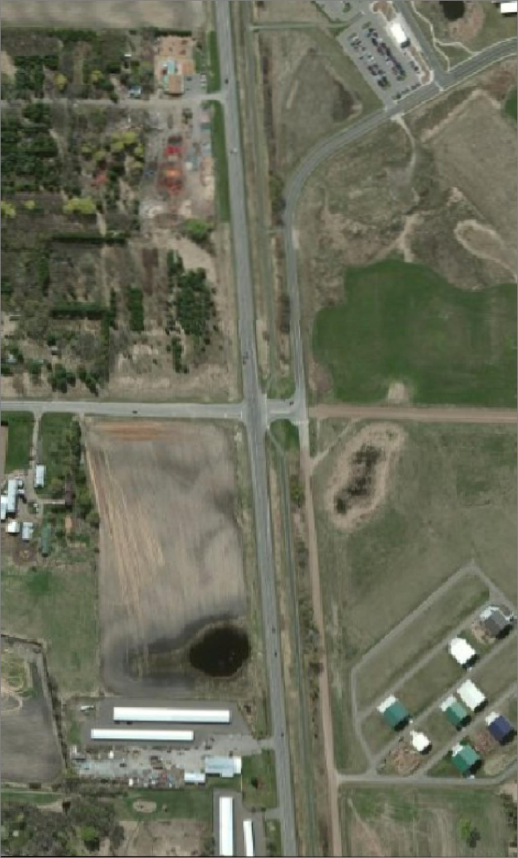
3 Roadway Construction History South County Line to Jct. TH 8 - TH 61 (Section 8206) TH 61 at CR 50 Project SP / B March 24, 2015 Page 3 Year SP Activity Width Net HMA Depth (in.) : B Original Grading Grade Widening and Plant-Mixed HMA (min) HMA, gravel shoulders Var. 2 1/ HMA surfacing 24 1 HMA shoulders / HMA mill (unknown depth); HMA overlay HMA mill and overlay (3 ½ inches) 24 0 Based on info available from Washington County, CR 50 has the following in-place section: 1 1/2 inches HMA (2006) 3 inches HMA (1992) 12 inches Class 5 aggregate base (1992) 24 inches Select Granular subbase (1992) Soil Borings Five power auger borings ( R- designation) were taken for the project to nominal depths of 5 feet below existing grade within the paved roadway. Eleven additional standard penetration borings ( ST- designation) were taken outside the existing roadway where embankment widening is proposed. A location sketch and boring logs can be found attached to this report. Measured bituminous pavement thickness averaged 4.3 inches and ranged from 3 to 6 inches in R-1 through R-5. It appears likely the borings were performed inadvertently in the paved shoulders. Additional coring was performed to verify mainline pavement and shoulder thickness as described below. The thickness of the apparent aggregate base was measured to be between 9 and 15 inches and averaged 12.4 inches. Topsoil penetrated in borings ST-1 through ST-11 ranged in thickness from 8 inches to 6 1/2 feet and averaged approximately 21 inches. The following soil types were encountered within the borings (upper 5 feet only). The roadway borings generally encountered loamy sand (LS), slightly plastic and plastic sandy loam (sl pl or pl SL) in the upper 5 feet, with more limited silty clay loam (SiCL) and loam (L). The upper 5 feet of borings in the widening area consisted of topsoil (TS) over clay (C), clay loam (CL), sandy clay loam (SCL) and loamy sand (LS).
4 Subgrade Soil Types TH 61 at CR 50 Project SP / B March 24, 2015 Page 4 Roadway Boring Subgrade Soils (Upper 5 feet, from Top to Bottom in Soil Column) TH 61 R-1 LS, sl pl SL, SiCL R-2 LS, sl pl SL R-3 LS, sl pl SL, L, sl pl SL R-4 LS, pl SL, LS R-5 LS ST-1 ST-2 ST-3 ST-4 ST-5 ST-6 ST-7 ST-8 ST-9 ST-10 ST-11 TS, CL, L TS, C, CL TS, SCL, CL TS, CL TS, CL TS, SCL, C TS TS, CL, C SC, CL TS, C TS, LS, C Soils at depths of 5 to 10 feet in ST-1 through ST-11 included slightly plastic sandy loam (sl pl SL), clay loam (CL), silty clay loam (SiCL), loam (L), clay (C) and loamy sand (LS). Pavement Cores Pavement cores performed adjacent to borings R-2, R-3 and R-4 each encountered 10 inches of HMA over a possible 2 to 3 inches of AGG. The AGG layer was difficult to identify due to the frozen conditions at the time of coring. We also verified the BIT section of the west shoulder with cores at locations shown in Figure 1. Thicknesses were as follows. All BIT materials appeared to be in good or very good condition. West Shoulder Cores Core Thickness (inches) CORE 1 4 CORE 2 4 CORE 3 3 1/2 CORE 4 2 CORE 5 3 3/4 CORE 6 4 1/2 CORE 7 2
5 TH 61 at CR 50 Project SP / B March 24, 2015 Page 5 FIGURE 1. LOCATIONS OF WEST SHOULDER CORES R-Value We did not perform Hveem stabilometer R-value tests for this project. Based on the predominant soil types in the upper portions (top 5 feet) of the current embankment, and assuming the soils used to construct the widened embankment will be similar, we have assumed a design R-value of 12 for pavement thickness design purposes. Traffic Trunk Highway (TH) 61 is a north-south roadway which has a functional classification of A-Minor Arterial. The 2012 AADT is 9,200 vpd on this stretch of TH 61. An official MnDOT traffic forecast was not available for this project; unofficially, we estimate approximately 1,013,000 equivalent single axle loads (ESALs) over a 20-year design period. County Road (CR) 50 has a functional classification of a collector and a 2012 AADT of 1,550 vpd.
6 TH 61 at CR 50 Project SP / B March 24, 2015 Page 6 Pavement Recommendations New HMA Facility Segment # From To Design Type TH 61 Widening 1 ALL New HMA (Widened) Mainline Pavement Thickness (inches) Lifts Mix Design/ Material Spec. Wear 4 2 SPWEB340C 2360 Non-Wear 4 2 SPNWB330B 2360 Smoothness Mainline Subsurface Special Provision 2399, Equation HMA-C Thickness (inches) Lifts Material Spec. Base 11 Class 5 or Subbase 16 Select Granular 2105 Subgrade Prep Compaction Testing Maximum Density Method ( D1) Maximum Density Method ( D1) Compaction Testing Penetration Index Method ( D.2.c) Penetration Index Method (2105.3F3) Specified Density (2105.3F1) The section as provided is intended to approximately match the existing mainline TH 61 per MnDOT recommendations, including the loamy sand shown in the soil borings to between 2 and 2 1/2 feet in depth. Width (ft) Width (ft) Notes Recommended shoulder section: TEMPORARY PAVEMENTS 4 inches SPWEB240B 15 inches Class 5 or 6 aggregate base 16 inches Select Granular subbase We understand mainline southbound traffic may be routed to the west shoulder for approximately two (2) months during construction. Information on BIT thickness for possible temporary pavements is provided above.
7 TH 61 at CR 50 Project SP / B March 24, 2015 Page 7 Miscellaneous Pavement Recommendations and Instructions to Designers Bituminous Pavement Provide tack coat between all bituminous layers and prior to placing any bituminous mixtures on existing pavement in accordance with Specification Use Joint Adhesive on longitudinal construction joints in accordance with Special Provision 2331 Pavement Joint Adhesive. Excavation and Embankment Construction Grading grade is defined as the bottom of aggregate base, typically Classes 3 through 6 (Standard Specification 3138). Construct embankment in accordance with Specification All new embankment and embankmentwidening material shall be Select Grading Material or Common Embankment in accordance with other requirements provided in Specification In any proposed widening construction, match the existing soil in the upper 5 feet of roadways to be widened with soil of a similar class, color, moisture content and performance characteristics. Do not place granular backfill adjacent to existing non-granular soils. Suitable grading material on the Project shall consist only of soils similar to those encountered below the upper portions of the roadway, including sandy loam and loamy sand. Non-granular soils shall only be considered suitable grading materials for widening where it can be verified that they substantially match those exposed in the upper portions of the existing embankment. Topsoil, debris, silt, organic material and other potentially unstable materials are not acceptable for grading. However, slightly organic soils (2 to 5 percent organic content by weight) may be used below the upper 3 feet of the embankment. In any case where granular embankments or backfill join non-granular soil embankments or backfill, provide a 1:20 (V:H) transition between the change in material to prevent an abrupt soils differential. Construct the 1:20 (V:H) transition such that the granular backfill material overlays the adjacent nongranular soil backfill. Where connecting new surfacing adjacent to any existing pavements to be widened, cut vertically to the bottom of the existing surfacing or to the bottom of the new surfacing design, whichever is deeper, then at a 2:1 (V:H) slope to the bottom of the recommended subgrade excavation.
8 TH 61 at CR 50 Project SP / B March 24, 2015 Page 8 Where connecting to existing roadways at the termini of proposed construction, cut vertically to the bottom of the existing surfacing or to the bottom of the new surfacing design, whichever is deeper, then at a 1:20 (V:H) taper to the bottom of the recommended subgrade excavation. Where matching into in-place crossroads, cut vertically to the bottom of the in-place surfacing, then at a 1:4 (V:H) slope to the bottom of the recommended subgrade excavation. Provide for 1:20 (V:H) tapers when changing subcut depths and subgrade materials. As a precautionary measure from a soils standpoint, traffic lanes to be used during construction must be delineated to keep vehicles a safe distance away from the adjacent excavation. The delineation should coincide with points established by projecting a 2(H):1(V) or flatter slope between the edge of the traffic surface and the bottom of the excavation. Provide a saw cut where placing new pavement next to inplace pavement to ensure a uniform joint. The level of compaction of the in-place soil is likely to vary along the length of the Project, and exposed soils should be made uniform and surface-compacted per the construction requirements of Specification to reduce the potential for excessive post-construction settlement or differential settlement of the embankment. Removals and Salvage When removing bituminous pavements adjacent to materials that will remain in place, full-depth sawcuts should be made perpendicular to the roadway centerline and along existing longitudinal pavement joints. Place sawcuts and longitudinal joints to avoid wheelpaths for the reconfigured lanes in the intersection. Recycle or reuse materials where feasible. Per Specification I, all surplus materials become the property of the Contractor. Dispose of these materials in accordance with a disposal plan approved by the Engineer. The disposal plan must comply with all applicable environmental regulations, permit requirements and Specification 2104 (Removing Pavement and Miscellaneous Structures). Disposal of materials before acceptance of the disposal plan is unauthorized work in accordance with Specification 1512 (Unacceptable and Unauthorized Work). Strip all topsoil and in-place slope dressing in areas to be disturbed by construction and if practical, stockpile for reuse as slope dressing. Slope dressing on this project is defined as the in-place topsoil or other soil placed during construction to provide a medium for establishing turf.
9 TH 61 at CR 50 Project SP / B March 24, 2015 Page 9 Geotechnical Recommendations Groundwater, Drainage, and Dewatering To facilitate drainage through the widened portion of the embankment, the Select Granular subbase in the widened embankment shall be graded and daylighted to allow for positive drainage to the adjacent ditches. Groundwater was encountered during drilling at a single location (ST-7, approximate elevation 922) in what appears to be a local condition near the low point of the existing profile. For most small and shortterm excavations within the soils present on site, sumps and pumps will generally be a suitable means to remove groundwater or additional water entering excavations. Special Treatments Based on the conditions encountered in the soil borings, swamp treatments or significant subgrade corrections are not expected to be necessary for this project. Some subcutting may be necessary to remove excessive topsoil in the vicinity of Boring ST-7. Wet conditions near this boring also provide the potential for unstable soils that will require removal and replacement to facilitate embankment construction. Topsoil and Turf Establishment Existing topsoil thicknesses range from 8 inches to 6 1/2 feet, with the average thickness being about 21 inches; excluding the deep topsoil at ST-7, the average thickness is approximately 16 inches. Strip all existing topsoil and slope dressing in areas to be disturbed by construction and reuse as slope dressing. Utilize all topsoil present on the project within the project limits. Smooth grade prior to placing sod, so there is no air gap between the bottom of the sod root system and the topsoil. Follow the Turf Establishment Recommendations for Metro District memo ( for seed type and placement recommendations. Borrow Shrinkage Factor Not used. Aggregate and Borrow Sources Not used. Additional Plan Notes Not used.
10
11
12 MINNESOTA DEPARTMENT OF TRANSPORTATION - GEOTECHNICAL SECTION LABORATORY LOG & TEST RESULTS - SUBSURFACE EXPLORATION UNIQUE NUMBER U.S. Customary Units State Project Location DEPTH Bridge No. or Job Desc. Co. Coordinate: X= Y= Latitude (North)= No Station-Offset Information Available Depth Elev. Lithology 8 inches of Topsoil. CLAY LOAM, fibers and roots, brown, moist, stiff. LOAM, brown, moist, stiff. Trunk Highway/Location TH 61 and CR 50 Longitude (West)= Classification SLIGHTLY PLASTIC SANDY LOAM, brown, moist, medium dense. (ft.) Bottom of Hole - 11 feet Water not observed while drilling. Water not observed to cave-in depth of 8 feet immediately after withdrawal of auger. Boring then backfilled. Drill Machine 7504 Hammer Drilling Operation SPT N60 REC MC (%) RQD 16 Boring No. ST-1 COH (psf) (%) (%) (ft) (pcf) ACL Core Breaks Soil Rock Ground Elevation (Surveyed) SHEET 1 of 1 Drilling Completed P200=46% Other Tests Or Remarks Formation or Member 1/8/15 Index Sheet Code Soil Class:N. Lund Rock Class: Edit: Date: 2/18/15 N:\GINT\PROJECTS\AX PROJECTS\2015\00082.GPJ
13 MINNESOTA DEPARTMENT OF TRANSPORTATION - GEOTECHNICAL SECTION LABORATORY LOG & TEST RESULTS - SUBSURFACE EXPLORATION UNIQUE NUMBER U.S. Customary Units State Project Location DEPTH Bridge No. or Job Desc. Co. Coordinate: X= Y= Latitude (North)= No Station-Offset Information Available Depth Elev. Lithology 10 inches of Topsoil. CLAY, brown to gray, moist, firm. Trunk Highway/Location TH 61 and CR 50 Longitude (West)= Classification (ft.) Drill Machine 7504 Hammer Drilling Operation SPT N60 REC 6 7 MC (%) RQD Boring No. ST-2 COH (psf) (%) (%) (ft) (pcf) ACL Core Breaks Soil Rock Ground Elevation (Surveyed) SHEET 1 of 1 Drilling Completed Other Tests Or Remarks Formation or Member 1/8/15 CLAY LOAM, light brown to gray, moist, firm to stiff Bottom of Hole - 11 feet Water not observed while drilling. Water not observed to cave-in depth of 7 1/2 feet immediately after withdrawal of auger. Boring then backfilled. 13 Index Sheet Code Soil Class:N. Lund Rock Class: Edit: Date: 2/18/15 N:\GINT\PROJECTS\AX PROJECTS\2015\00082.GPJ
14 MINNESOTA DEPARTMENT OF TRANSPORTATION - GEOTECHNICAL SECTION LABORATORY LOG & TEST RESULTS - SUBSURFACE EXPLORATION UNIQUE NUMBER U.S. Customary Units State Project Location DEPTH Bridge No. or Job Desc. Co. Coordinate: X= Y= Latitude (North)= No Station-Offset Information Available Depth Elev. Lithology 12 inches of Topsoil. SANDY CLAY LOAM, roots, sample from cuttings dark brown, moist, firm. CLAY LOAM, brown, moist, firm. SILTY CLAY LOAM, brown, moist, firm. CLAY LOAM, brown, moist, stiff. Trunk Highway/Location TH 61 and CR 50 Longitude (West)= Classification (ft.) Bottom of Hole - 11 feet Water not observed while drilling. Water not observed to cave-in depth of 7 1/2 feet immediately after withdrawal of auger. Boring then backfilled. Drill Machine 7504 Hammer Drilling Operation SPT N60 REC MC (%) RQD 24 Boring No. ST-3 COH (psf) (%) (%) (ft) (pcf) ACL Core Breaks Soil Rock Ground Elevation (Surveyed) SHEET 1 of 1 Drilling Completed Other Tests Or Remarks Formation or Member 1/8/15 Index Sheet Code Soil Class:N. Lund Rock Class: Edit: Date: 2/18/15 N:\GINT\PROJECTS\AX PROJECTS\2015\00082.GPJ
15 MINNESOTA DEPARTMENT OF TRANSPORTATION - GEOTECHNICAL SECTION LABORATORY LOG & TEST RESULTS - SUBSURFACE EXPLORATION UNIQUE NUMBER U.S. Customary Units State Project Location DEPTH Bridge No. or Job Desc. Co. Coordinate: X= Y= Latitude (North)= No Station-Offset Information Available Depth Elev. Lithology 18 inches of Topsoil. CLAY LOAM, roots and fibers, dark gray brown, moist, firm. CLAY LOAM, light brown, moist, firm. LOAM, brown, moist, firm to stiff. Trunk Highway/Location TH 61 and CR 50 Longitude (West)= Classification (ft.) Drill Machine 7504 Hammer Drilling Operation SPT N60 REC MC (%) RQD Boring No. ST-4 COH (psf) (%) (%) (ft) (pcf) ACL Core Breaks Soil Rock Ground Elevation (Surveyed) SHEET 1 of 1 Drilling Completed Other Tests Or Remarks Formation or Member 1/8/ Bottom of Hole - 11 feet Water not observed while drilling. Water not observed to cave-in depth of 7 1/2 feet immediately after withdrawal of auger. Boring then backfilled Index Sheet Code Soil Class:N. Lund Rock Class: Edit: Date: 2/18/15 N:\GINT\PROJECTS\AX PROJECTS\2015\00082.GPJ
16 MINNESOTA DEPARTMENT OF TRANSPORTATION - GEOTECHNICAL SECTION LABORATORY LOG & TEST RESULTS - SUBSURFACE EXPLORATION UNIQUE NUMBER U.S. Customary Units State Project Bridge No. or Job Desc. Trunk Highway/Location TH 61 and CR 50 Location Co. Coordinate: X= Y= (ft.) Latitude (North)= Longitude (West)= No Station-Offset Information Available DEPTH Depth Elev. Lithology Classification Drill Machine 7504 Hammer Drilling Operation SPT N60 REC MC (%) RQD Boring No. ST-5 COH (psf) (%) (%) (ft) (pcf) ACL Core Breaks Soil Rock Ground Elevation (Surveyed) SHEET 1 of 1 Drilling Completed Other Tests Or Remarks Formation or Member 1/8/ inches of Topsoil. CLAY LOAM, fibers and roots, gray and brown, moist, firm to stiff LOAM, brown and gray, moist, stiff to very stiff Bottom of Hole - 11 feet Water not observed while drilling. Water not observed to cave-in depth of 8 feet immediately after withdrawal of auger. Boring then backfilled. 19 Index Sheet Code Soil Class:N. Lund Rock Class: Edit: Date: 2/18/15 N:\GINT\PROJECTS\AX PROJECTS\2015\00082.GPJ
17 MINNESOTA DEPARTMENT OF TRANSPORTATION - GEOTECHNICAL SECTION LABORATORY LOG & TEST RESULTS - SUBSURFACE EXPLORATION UNIQUE NUMBER U.S. Customary Units State Project Location DEPTH Bridge No. or Job Desc. Co. Coordinate: X= Y= Latitude (North)= No Station-Offset Information Available Depth Elev. Lithology 12 inches of Topsoil. SANDY CLAY LOAM, fine- grained, brown, moist, firm. CLAY, gray and brown, moist, soft to firm. LOAM, brown, moist, stiff. Trunk Highway/Location TH 61 and CR 50 Longitude (West)= Classification (ft.) Bottom of Hole - 11 feet Water not observed while drilling. Water not observed to cave-in depth of 7 1/2 feet immediately after withdrawal of auger. Boring then backfilled. Drill Machine 7504 Hammer Drilling Operation SPT N60 REC MC (%) RQD 19 Boring No. ST-6 COH (psf) (%) (%) (ft) (pcf) ACL Core Breaks Soil Rock Ground Elevation (Surveyed) SHEET 1 of 1 Drilling Completed P200=46% Other Tests Or Remarks Formation or Member 1/8/15 Index Sheet Code Soil Class:N. Lund Rock Class: Edit: Date: 2/18/15 N:\GINT\PROJECTS\AX PROJECTS\2015\00082.GPJ
18 MINNESOTA DEPARTMENT OF TRANSPORTATION - GEOTECHNICAL SECTION LABORATORY LOG & TEST RESULTS - SUBSURFACE EXPLORATION UNIQUE NUMBER U.S. Customary Units State Project Bridge No. or Job Desc. Trunk Highway/Location TH 61 and CR 50 Location Co. Coordinate: X= Y= (ft.) Latitude (North)= Longitude (West)= No Station-Offset Information Available DEPTH Depth Elev. Lithology Classification Drill Machine 7504 Hammer Drilling Operation SPT N60 REC MC (%) RQD Boring No. ST-7 COH (psf) (%) (%) (ft) (pcf) ACL Core Breaks Soil Rock Ground Elevation (Surveyed) SHEET 1 of 1 Drilling Completed Other Tests Or Remarks Formation or Member 1/8/15 6 1/2 feet of Topsoil LOAMY SAND, fine- to medium-grained, brown, waterbearing, very loose. CLAY, gray, waterbearing, firm. Bottom of Hole - 11 feet Water observed at 6 1/2 feet with 6 1/2 feet of hollow-stem auger in the ground. Water not observed to cave-in depth of 6 1/2 feet immediately after withdrawal of auger. Boring then backfilled OC=4% Index Sheet Code Soil Class:N. Lund Rock Class: Edit: Date: 2/18/15 N:\GINT\PROJECTS\AX PROJECTS\2015\00082.GPJ
19 MINNESOTA DEPARTMENT OF TRANSPORTATION - GEOTECHNICAL SECTION LABORATORY LOG & TEST RESULTS - SUBSURFACE EXPLORATION UNIQUE NUMBER U.S. Customary Units State Project Location DEPTH Bridge No. or Job Desc. Co. Coordinate: X= Y= Latitude (North)= No Station-Offset Information Available Depth Elev. Lithology 12 inches of Topsoil. CLAY LOAM, gray and reddish brown, moist, firm. CLAY, gray and brown, wet, firm. CLAY LOAM, brown, moist, stiff. Trunk Highway/Location TH 61 and CR 50 Longitude (West)= Classification (ft.) Drill Machine 7504 Hammer Drilling Operation SPT N60 REC MC (%) RQD 19 Boring No. ST-8 COH (psf) (%) (%) (ft) (pcf) ACL Core Breaks Soil Rock Ground Elevation (Surveyed) SHEET 1 of 1 Drilling Completed Other Tests Or Remarks Formation or Member 1/8/ Bottom of Hole - 11 feet Water not observed while drilling. Water not observed to cave-in depth of 7 1/2 feet immediately after withdrawal of auger. Boring then backfilled. 11 Index Sheet Code Soil Class:N. Lund Rock Class: Edit: Date: 2/18/15 N:\GINT\PROJECTS\AX PROJECTS\2015\00082.GPJ
20 MINNESOTA DEPARTMENT OF TRANSPORTATION - GEOTECHNICAL SECTION LABORATORY LOG & TEST RESULTS - SUBSURFACE EXPLORATION UNIQUE NUMBER U.S. Customary Units State Project Location DEPTH Bridge No. or Job Desc. Co. Coordinate: X= Y= Latitude (North)= No Station-Offset Information Available Depth Elev. Lithology 12 inches of Topsoil. SANDY CLAY, trace fibers and roots, brown, moist, firm. CLAY LOAM, brown and gray, moist, stiff. LOAM, brown, moist, stiff. Trunk Highway/Location TH 61 and CR 50 Longitude (West)= Classification (ft.) Drill Machine 7504 Hammer Drilling Operation SPT N60 REC MC (%) RQD Boring No. ST-9 COH (psf) (%) (%) (ft) (pcf) ACL Core Breaks Soil Rock Ground Elevation (Surveyed) SHEET 1 of 1 Drilling Completed Other Tests Or Remarks Formation or Member 1/8/ Bottom of Hole - 11 feet Water not observed while drilling. Water not observed to cave-in depth of 7 1/2 feet immediately after withdrawal of auger. Boring then backfilled. 14 Index Sheet Code Soil Class:N. Lund Rock Class: Edit: Date: 2/18/15 N:\GINT\PROJECTS\AX PROJECTS\2015\00082.GPJ
21 MINNESOTA DEPARTMENT OF TRANSPORTATION - GEOTECHNICAL SECTION LABORATORY LOG & TEST RESULTS - SUBSURFACE EXPLORATION UNIQUE NUMBER U.S. Customary Units State Project Bridge No. or Job Desc. Trunk Highway/Location TH 61 and CR 50 Location Co. Coordinate: X= Y= (ft.) Latitude (North)= Longitude (West)= No Station-Offset Information Available DEPTH Depth Elev. Lithology Classification Drill Machine 7504 Hammer Drilling Operation SPT N60 REC MC (%) RQD Boring No. ST-10 COH (psf) (%) (%) (ft) (pcf) ACL Core Breaks Soil Rock Ground Elevation (Surveyed) SHEET 1 of 1 Drilling Completed Other Tests Or Remarks Formation or Member 1/8/15 3 feet of Topsoil CLAY, gray, moist, firm CLAY LOAM, dark gray, moist, firm to stiff Bottom of Hole - 11 feet Water not observed to cave-in depth of 7 feet immediately after withdrawal of auger. Boring then backfilled. 9 Index Sheet Code Soil Class:N. Lund Rock Class: Edit: Date: 2/18/15 N:\GINT\PROJECTS\AX PROJECTS\2015\00082.GPJ
22 MINNESOTA DEPARTMENT OF TRANSPORTATION - GEOTECHNICAL SECTION LABORATORY LOG & TEST RESULTS - SUBSURFACE EXPLORATION UNIQUE NUMBER U.S. Customary Units State Project Location DEPTH Bridge No. or Job Desc. Co. Coordinate: X= Y= Latitude (North)= No Station-Offset Information Available Depth Elev. Lithology 12 inches of Topsoil. LOAMY SAND, fine- grained, brown and gray, moist, loose. CLAY, brown and gray, wet, soft. Trunk Highway/Location TH 61 and CR 50 Longitude (West)= Classification CLAY LOAM, brown and gray, moist, firm to stiff. (ft.) Drill Machine 7504 Hammer Drilling Operation SPT N60 REC MC (%) RQD 16 Boring No. ST-11 COH (psf) (%) (%) (ft) (pcf) ACL Core Breaks Soil Rock Ground Elevation (Surveyed) SHEET 1 of 1 Drilling Completed P200=46% Other Tests Or Remarks Formation or Member 1/8/ Bottom of Hole - 11 feet Water not observed while drilling. Water not observed to cave-in depth of 7 feet immediately after withdrawal of auger. Boring then backfilled. 11 Index Sheet Code Soil Class:N. Lund Rock Class: Edit: Date: 2/18/15 N:\GINT\PROJECTS\AX PROJECTS\2015\00082.GPJ
23 MINNESOTA DEPARTMENT OF TRANSPORTATION - GEOTECHNICAL SECTION LABORATORY LOG & TEST RESULTS - SUBSURFACE EXPLORATION UNIQUE NUMBER U.S. Customary Units State Project Location DEPTH Bridge No. or Job Desc. Co. Coordinate: X= Y= Latitude (North)= No Station-Offset Information Available Depth Elev. Lithology Trunk Highway/Location TH 61 and CR 50 Longitude (West)= Classification (ft.) 3 inches of bituminous. 15 inches of aggregate base. LOAMY SAND, fine- grained, trace Gravel, brown, moist, frozen. SLIGHTLY PLASTIC SANDY LOAM, fine- grained, gray, moist. SILTY CLAY LOAM, slightly organic, trace roots, black, moist. Bottom of Hole - 5 feet Water not observed while drilling. Water not observed to cave-in depth of 4 feet immediately after withdrawal of auger. Drill Machine 7514 Hammer Drilling Operation SPT N60 REC MC (%) RQD Boring No. R-1 COH (psf) (%) (%) (ft) (pcf) ACL Core Breaks Soil Rock Ground Elevation (Surveyed) SHEET 1 of 1 Drilling Completed Other Tests Or Remarks Formation or Member 1/12/15 Index Sheet Code Soil Class:N. Lund Rock Class: Edit: Date: 2/18/15 N:\GINT\PROJECTS\AX PROJECTS\2015\00082.GPJ
24 MINNESOTA DEPARTMENT OF TRANSPORTATION - GEOTECHNICAL SECTION LABORATORY LOG & TEST RESULTS - SUBSURFACE EXPLORATION UNIQUE NUMBER U.S. Customary Units State Project Location DEPTH Bridge No. or Job Desc. Co. Coordinate: X= Y= Latitude (North)= No Station-Offset Information Available Depth Elev. Lithology 6 inches of bituminous. 11 inches of aggregate base. LOAMY SAND, fine- grained, brown, moist, frozen. SLIGHTLY PLASTIC SANDY LOAM, fine- grained, dark gray and brown, moist. Bottom of Hole - 5 feet Water not observed while drilling. Boring then backfilled. Trunk Highway/Location TH 61 and CR 50 Longitude (West)= Classification (ft.) Drill Machine 7514 Hammer Drilling Operation SPT N60 REC MC (%) RQD Boring No. R-2 COH (psf) (%) (%) (ft) (pcf) ACL Core Breaks Soil Rock Ground Elevation (Surveyed) SHEET 1 of 1 Drilling Completed Other Tests Or Remarks Formation or Member 1/12/15 Index Sheet Code Soil Class:N. Lund Rock Class: Edit: Date: 2/18/15 N:\GINT\PROJECTS\AX PROJECTS\2015\00082.GPJ
25 State Project Location DEPTH 5 MINNESOTA DEPARTMENT OF TRANSPORTATION - GEOTECHNICAL SECTION Bridge No. or Job Desc. Co. Coordinate: X= Y= Latitude (North)= No Station-Offset Information Available Depth Elev. LABORATORY LOG & TEST RESULTS - SUBSURFACE EXPLORATION Lithology UNIQUE NUMBER U.S. Customary Units Trunk Highway/Location TH 61 and CR 50 Longitude (West)= Classification (ft.) 4 1/2 inches of bituminous. 9 inches of aggregate base. LOAMY SAND, fine- grained, trace Gravel, brown, moist, frozen. SLIGHTLY PLASTIC SANDY LOAM, fine- grained, dark brown, moist, frozen. LOAM, trace Gravel, gray, moist. SLIGHTLY PLASTIC SANDY LOAM, fine- grained, black and dark brown, moist. Bottom of Hole - 5 feet Water not observed while drilling. Water not observed to cave-in depth of 4 feet immediately after withdrawal of auger. Boring then backfilled. Drill Machine 7514 Hammer Drilling Operation SPT N60 REC MC (%) RQD 16 Boring No. R-3 COH (psf) (%) (%) (ft) (pcf) ACL Core Breaks Soil Rock Ground Elevation (Surveyed) SHEET 1 of 1 Drilling Completed P200=40% Other Tests Or Remarks Formation or Member 1/12/15 Index Sheet Code Soil Class:N. Lund Rock Class: Edit: Date: 2/18/15 N:\GINT\PROJECTS\AX PROJECTS\2015\00082.GPJ
26 MINNESOTA DEPARTMENT OF TRANSPORTATION - GEOTECHNICAL SECTION LABORATORY LOG & TEST RESULTS - SUBSURFACE EXPLORATION UNIQUE NUMBER U.S. Customary Units State Project Location DEPTH Bridge No. or Job Desc. Co. Coordinate: X= Y= Latitude (North)= No Station-Offset Information Available Depth Elev. Lithology Trunk Highway/Location TH 61 and CR 50 Longitude (West)= Classification (ft.) 4 inches of bituminous. 12 inches of aggregate base. LOAMY SAND, fine- grained, trace Gravel, brown, moist, frozen. PLASTIC SANDY LOAM, fine- grained, dark brown, moist. SLIGHTLY PLASTIC SANDY LOAM, slightly organic, finegrained, black, moist. LOAMY SAND, fine- grained, dark brown, moist. Bottom of Hole - 5 feet Water not observed while drilling. Water not observed to cave-in depth of 4 feet immediately after withdrawal of auger. Boring then backfilled. Drill Machine 7514 Hammer Drilling Operation SPT N60 REC MC (%) RQD 21 Boring No. R-4 COH (psf) (%) (%) (ft) (pcf) ACL Core Breaks Soil Rock Ground Elevation (Surveyed) SHEET 1 of 1 Drilling Completed OC=4% Other Tests Or Remarks Formation or Member 1/12/15 Index Sheet Code Soil Class:N. Lund Rock Class: Edit: Date: 2/18/15 N:\GINT\PROJECTS\AX PROJECTS\2015\00082.GPJ
= No Station-Offset Information Available Depth Elev. Lithology 4 inches of bituminous.")
27 MINNESOTA DEPARTMENT OF TRANSPORTATION - GEOTECHNICAL SECTION LABORATORY LOG & TEST RESULTS - SUBSURFACE EXPLORATION UNIQUE NUMBER U.S. Customary Units State Project Location DEPTH Bridge No. or Job Desc. Co. Coordinate: X= Y= Latitude (North)= No Station-Offset Information Available Depth Elev. Lithology 4 inches of bituminous. 15 inches of aggregate base. Trunk Highway/Location TH 61 and CR 50 Longitude (West)= Classification LOAMY SAND, fine- grained, trace Gravel, brown, moist, frozen. (ft.) Bottom of Hole - 5 feet Water not observed while drilling. Water not observed to cave-in depth of 4 feet immediately after withdrawal of auger. Boring then backfilled. Drill Machine 7514 Hammer Drilling Operation SPT N60 REC MC (%) RQD Boring No. R-5 COH (psf) (%) (%) (ft) (pcf) ACL Core Breaks Soil Rock Ground Elevation (Surveyed) SHEET 1 of 1 Drilling Completed Other Tests Or Remarks Formation or Member 1/12/15 Index Sheet Code Soil Class:N. Lund Rock Class: Edit: Date: 2/18/15 N:\GINT\PROJECTS\AX PROJECTS\2015\00082.GPJ
28 Minnesota Department of Transportation Geotechnical Section Boring Log Descriptive Terminology (English Units) USER NOTES, ABBREVIATIONS AND DEFINITIONS - Additional information available in Geotechnical Manual. This boring was made by ordinary and conventional methods and with care deemed adequate for the Department's design purposes. Since this boring was not taken to gather information relating to the construction of the project, the data noted in the field and recorded may not necessarily be the same as that which a contractor would desire. While the Department believes that the information as to the conditions and materials reported is accurate, it does not warrant that the information is necessarily complete. This information has been edited or abridged and may not reveal all the information which might be useful or of interest to the contractor. Consequently, the Department will make available at its offices, the field logs relating to this boring. Since subsurface conditions outside each borehole are unknown, and soil, rock and water conditions cannot be relied upon to be consistent or uniform, no warrant is made that conditions adjacent to this boring will necessarily be the same as or similar to those shown on this log. Furthermore, the Department will not be responsible for any interpretations, assumptions, projections or interpolations made by contractors, or other users of this log. Water levels recorded on this log should be used with discretion since the use of drilling fluids in borings may seriously distort the true field conditions. Also, water levels in cohesive soils often take extended periods of time to reach equilibrium and thus reflect their true field level. Water levels can be expected to vary both seasonally and yearly. The absence of notations on this log regarding water does not necessarily mean that this boring was dry or that the contractor will not encounter subsurface water during the course of construction. WATER MEASUREMENT AB...After Bailing AC...After Completion AF...After Flushing w/c...with Casing w/m...with Mud WSD...While Sampling/Drilling w/aug...with Hollow Stem Auger MISCELLANEOUS NA...Not Applicable w/...with w/o...with out sat...saturated DRILLING OPERATIONS AUG...Augered CD...Core Drilled DBD...Disturbed by Drilling DBJ...Disturbed by Jetting PD...Plug Drilled ST...Split Tube (SPT test) Index Sheet No. 3.0 March 2003 G:\geotech\Public\Forms\INDEX30.doc TW...Thinwall (Shelby Tube) WS...Wash Sample NSR...No Sample Retrieved WH...Weight of Hammer WR...Weight of Rod Mud...Drilling Fluids in Sample CS...Continuous Sample SOIL/CORE TESTS SPT N 60...ASTM D1586 Modified Blows per foot with 140 lb. hammer and a standard energy of 210 ft-lbs. This energy represents 60% of the potential energy of the system and is the average energy provided by a Rope & Cathead system. MC...Moisture Content COH...Cohesion?...Sample Density LL...Liquid Limit PI...Plasticity Index F...Phi Angle REC...Percent Core Recovered RQD...Rock Quality Description (Percent of total core interval consisting of unbroken pieces 4 inches or longer) ACL...Average Core Length (Average length of core that is greater than 4 inches long) Core Breaks...Number of natural core breaks per 2-foot interval. DISCONTINUITY SPACING Fractures Distance Bedding Very Close...<2 inches...very Thin Close inches...thin Mod. Close inches...medium Wide...>36 inches...thick Vane Shear Test DRILLING SYMBOLS Washed Sample WS (Collected during plug drilling) PD CS A/J Jet A/P Augered Plug Drilled Split Tube Sample (SPT N60 2 in. spilt tube with liners) Thin Wall Sample (3 in. Shelby Tube) Core Drilled (NV Core Barrel unless otherwise noted) Continuous Soil Sample Augered & Jetted Jetted Augered & Plug Drilled 100% 90 % Sand 80 S LS RELATIVE DENSITY Compactness - Granular Soils BPF very loose loose medium dense dense very dense...>50 Consistency - Cohesive Soils BPF very soft soft firm stiff very stiff hard very hard...> 60 COLOR blk...black wht...white grn...green brn...brown orng...orange yel...yellow dk...dark lt...light IOS...Iron Oxide Stained GRAIN SIZE /PLASTICITY VF...Very Fine pl...plastic F...Fine slpl...slightly Cr...Coarse Plastic SOIL/ROCK TERMS C...Clay Lmst...Limestone L...Loam Sst...Sandstone S...Sand Dolo...Dolostone Si...Silt wx...weathered G...Gravel (No. 10 Sieve to 3 inches) Bldr...Boulder (over 3 inches) T...till (unsorted, nonstratified glacial deposits) Mn/DOT Triangular Textural Soil Classification System SC SCL 30 (plastic) SL (slightly plastic) C CL L % Silt 100 % Si L SiC SiCL % Clay Si %
29 MinniESAL Traffic Forecast Program -for use on County and City projects GENERAL INFORMATION Date: Forecasted by: City or County: Project #: Project Description: Route: Base Year (i.e., opening to traffic): Number of Lanes (both directions): February 20, 2015 NGL Washington SP Widening for Turn Lane TH HISTORICAL AADT (minimum of two years) Year AADT ,500 Regression 0.94 Results: ,700 R 2 = 1.8% ,200 Growth 4 Rate = 1.8 % Base Year AADT year AADT VEHICLE CLASSIFICATION Please select one of the following: TRUE Site Specific VCC Data Vehicle Type URBAN (2005 Default VC Data - 3.9% HCADT) RURAL (2005 Default VC Data - 8.9% HCADT) "A" Segment Forecast Vehicle Class % Truck ESAL Factors Base Year Volume FLEXIBLE RIGID 2AX-6TIRE SU 1.5% AX+ SU 0.5% AX TST 0.1% AX TST 0.1% AX+ TST 0.9% TR TR, BUSES 0.5% TWIN TRAILERS 0.0% % "20" Year Flexible Forecast 1,013,000 ESALs "20" Year Rigid Forecast 1,437,000 ESALs "35" Year Rigid Forecast 2,748,000 ESALs Questions? Please contact Mn/DOT's Traffic Forecasting Section ( )
30 MnPAVE Design Summary MnPAVE Simulation Input File: TH61 Confidence and Reliability do not necessarily agree. All layer values are reduced based on Confidence. Monte Carlo Reliability randomly selects values for each layer. Use Reliability for final design. Preliminary Life Estimate 20-Year Reliability Fatigue Rutting Fatigue Rutting >50 years >50 years 100% 100% Project Information District County City Metro Washington Forest Lake Project Number Route Reference Post from to Letting Date Construction Type 02/20/15 RC Climate Information Season Mode Days Designer Washington County Soils Engineer Braun Intertec Location 45 1 Latitude, Longitude Structural Information (Design Level: Intermediate) Layer Type Subtype Height (in.) 1 (lift 1) HMA PG (lift 2) HMA PG Aggregate Base Mn/DOT Class Aggregate Subbase Mn/DOT Select Granular Engineered Soil R-Value = 12 (CL) Undisturbed Soil Engineered Soil Modulus/2 Traffic Information Load Type Total Repetitions ESALs 1,012,999 Notes Cooperative agreement project; embankment widening and turn lane construction Braun Intertec project B The Minnesota Department of Transportation makes no guarantee or warranty, either express or implied, with respect to the reuse of the data provided herewith, regardless of its format or means of its transmission. The user accepts the data "as is", and assumes all risks associated with its use. By accepting this data, the user agrees not to transmit this data or provide access to it or any part of it to another party unless the user shall include with the data a copy of this disclaimer. The Minnesota Department of Transportation assumes no responsibility, actual or consequential, for damage that results from any user s reliance on this data. Printed Tuesday, March 24, 2015 at 12:44:09
31
32
33
34
35
36
37
38
39
40
41
42
43
44
45
46
47
48
49
50
51
52
53
54
55
56
57
58
59
60
61
62
63
64
65
66
67
68
69
70
71
72
73
74
75
76
77
78
79
80
81
82
83
84
85
86
87
88
89
90
91
92
93
94
SOIL BORING LOCATION SKETCH GEOTECHNICAL EVALUATION ST. CROIX TRAVEL AND INFO CENTER POND 1-94, WEST OF STAGECOACH TRAIL LAKELAND, MINNESOTA
 F:\16\B16326.dwg,Geotech.00,3/1/17 6:17:41 PM N DENOTES APPROXIMATE LOCATION OF STANDARD PENETRATION TEST BORING 7' 0 10' SCALE: 1"= 10' Sheet: of Fig: Project No: B16326.00 Drawing No: B16326 Scale: 1"=
Minnesota Department of Transportation MEMO Office of Materials Mailstop Gervais Avenue Maplewood, MN 55109
 Minnesota Department of Transportation MEMO Office of Materials Mailstop 64 00 Gervais Avenue Maplewood, MN 9 Date: July 31, 08 To: Robert Evbayekha, Final Design Waters Edge From: Jeff Narr, Graduate
Gary Person, Foundation Engineer Geotechnical Engineering Section
 Minnesota Department of Transportation MEMO Mailstop 64 14 Gervais Avenue Maplewood, MN 9 DATE: November 3 rd, 214 TO: FROM: CONCUR: Bruce Johnson, Project Manager Metro Design Hossana Teklyes, Assist.
Test Pit Observation Report. Albertville Business Park 67th Street to 70th Street NE Albertville, Minnesota. Prepared for.
 Test Pit Observation Report Albertville Business Park 67th Street to 70th Street NE Albertville, Minnesota Prepared for Fehn Companies Professional Certification: I hereby certify that this plan, specification,
Advanced Foundation Engineering. Soil Exploration
 Shahrood University of Technology Department of Geotechnical Engineering Advanced Foundation Engineering Soil Exploration Mohsen Keramati, Ph.D. Assistant Professor 1 - Introduction The field and laboratory
Geotechnical Exploration and Evaluation Report
 Geotechnical Exploration and Evaluation Report UNF Transportation Projects Osprey Ridge Road Extension Jacksonville, Florida CSI Geo Project No.: --- Arcadis Project No.: JK. Prepared by CSI Geo, Inc.
SITE AND PROJECT DESCRIPTION
 51331 W. Pontiac Trail, Wixom, MI 48393 248.486.5 Main 248.486.5050 Fax February 11, 2015 Ms. Amy Kuras, Landscape Architect City of Ann Arbor Parks and Recreation Services 301 E. Huron Street Ann Arbor,
Pontiac Trail 1" = 80' B-1 B-2 B-3 B-4 B-5. to WB S23 C SB U M 14. a c Trl
 Pontiac Trail ONN S23 C SB U 4 M1 EB to WB M 14 B-1 3369 B-2 3227 a Ponti c Trl 318 B-3 7 7 40 0 B-4 307 302 B- 300 3 3 33 1" = 80' Pontiac Trail Dhu Varren Rd 33 33 33 33 128 1" = 80' 100 1290 33 2980
Sydney Road Reclaimed Water Main, Plant City, Florida. Prepared for: Jones Edmunds & Associates, Inc.
 . Geotechnical Report Sydney Road Reclaimed Water Main, Plant City, Florida Prepared for: Jones Edmunds & Associates, Inc. Prepared by: MADRID ENGINEERING GROUP, INC. 2030 Hwy 60 E. Bartow, FL 33830 863-533-9007
JULY 23, 2018 PROJECT REPORT OF GEOTECHNICAL EXPLORATIONS CASS GILBERT MEMORIAL PARK SOLAR GARDEN CAPITOL COMPLEX ST.
 This document is made available electronically by the Minnesota Legislative Reference Library as part of an ongoing digital archiving project. http://www.leg.state.mn.us/lrl/lrl.asp Independent Indepedent
July 4, 2007 PAVEMENT MANUAL 5-2.0(1) Chapter Five DESIGN
 Chapter Five DESIGN") July 4, 2007 PAVEMENT MANUAL 5-2.0(1) 5-1.0 DESIGN CONSIDERATIONS Chapter Five DESIGN The activities involved in the provision of pavements can be divided into three groups. First, there is the geotechnical
July 4, 2007 PAVEMENT MANUAL 5-2.0(1) 5-1.0 DESIGN CONSIDERATIONS Chapter Five DESIGN The activities involved in the provision of pavements can be divided into three groups. First, there is the geotechnical
APPENDIX E COMPACTION CHARACTERISTICS AND EQUIPMENT
 APPENDIX E COMPACTION CHARACTERISTICS AND EQUIPMENT When the Materials Division designs a pavement structure, there are a number of factors that influence it s outcome. Projected traffic counts, percentage
SECTION 900 TURF ESTABLISHMENT
 SECTION 900 901.0 DESCRIPTION This section covers the furnishing of all labor, materials, tools, equipment and performances of all work and services necessary or incidental to turf restoration as indicated
CAPRICORN MUNICIPAL DEVELOPMENT GUIDELINES
 CAPRICORN MUNICIPAL DEVELOPMENT GUIDELINES PAVEMENT DESIGN D2 DESIGN GUIDELINES CAPRICORN MUNICIPAL DEVELOPMENT GUIDELINES D2 ISSUE: NO:3 September 2014 TABLE OF CONTENTS CLAUSE CONTENTS PAGE GENERAL...
VALLEY COUNTY MINIMUM STANDARDS FOR PRIVATE ROAD DESIGN AND CONSTRUCTION
 MINIMUM STANDARDS FOR PRIVATE ROAD DESIGN AND CONSTRUCTION Adopted November 28, 2005 TABLE OF CONTENTS DEFINITION OF TERMS...II I. DESIGN CRITERIA... 1 A. GENERAL DESIGN CRITERIA... 1 B. ROADWAY CLASSIFICATION...
Geotechnical Exploration and Evaluation Report Revision No. 01
 Geotechnical Exploration and Evaluation Report Revision No. UNF Transportation Projects Eco Road Extension Jacksonville, Florida CSI Geo Project No.: --- Arcadis Project No.: JK. Prepared by CSI Geo, Inc.
Wisconsin Contractors Institute Continuing Education
 Wisconsin Contractors Institute Continuing Education Erosion & Sediment Control Course # 12775 2 hours Wisconsin Contractors Institute N27 W23953 Paul Road, Suite 203 Pewaukee, WI 53072 Website: www.wicontractorsinstitute.com
The City of Winnipeg Bid Opportunity No GEOTECHNICAL REPORT - TEST HOLE LOGS
 The City of Winnipeg Bid Opportunity No. 88-6 GEOTECHNICAL REPORT - TEST HOLE LOGS The City of Winnipeg Bid Opportunity 88-6 Template Version: C44 TEST HOLE LOGS TABLE OF CONTENTS TEST HOLE LOGS FOR DEARBORN
PROPOSED DRAINAGE PATTERNS
 1121 1118.50 Basin Floor 1120 1119 0 N 100 200 PROPOSED DRAINAGE PATTERNS Deroiser Drive Riverwood Drive County 260 0 100 200 Project Name: Riverwood Drive LITTLE FALLS TOWNHOMES Project Location: LITTLE
UNIFIED FACILITIES GUIDE SPECIFICATIONS
 USACE / NAVFAC / AFCEC / NASA UFGS-02 66 00 (February 2010) ----------------------------- Preparing Activity: USACE Superseding UFGS-02 66 00 (April 2006) UNIFIED FACILITIES GUIDE SPECIFICATIONS References
APPENDIX E: UC Berkeley Laboratory Testing and ILIT In-Situ Field Vane Shear Testing
 New Orleans Systems Independent Levee Hurricane Katrina Investigation Team July 31, 26 APPENDIX E: UC Berkeley Laboratory Testing and ILIT In-Situ Field Vane Shear Testing A series of laboratory tests
DESIGN SCENE SUBJECT INDEX
 DESIGN SCENE SUBJECT INDEX CHAPTER 1: TITLE SHEET and GENERAL LAYOUT AREA OF ENVIRONMENTAL SENSITIVITY BRIDGE & APPROACH PLANS CONSTRUCTION PLAN FOR EXCEPTIONS EXCEPTION CLARIFICATION GOVERNING SPECIFICATIONS
STATEMENT OF PHYSICAL CHARACTERISTICS AND AGRICULTURAL LAND CLASSIFICATION WITTON PARK, COUNTY DURHAM PROPOSED QUARRY EXTENSION DECEMBER 1992

University Park Subdivision Street Assessment Report
 University Park Subdivision Street Assessment Report Prepared for: University Park Subdivision TABLE OF CONTENTS Introduction... 3 Existing Conditions Analysis... 4 Street Improvements... 5 Existing:...
Technical Bullet Series on Clay Brick Pavers
 2701 Shorefair Drive, Winston-Salem, NC 27105 pinehallbrick.com 1-800-334-8689 Technical Bullet Series on Clay Brick Pavers #4 Designing For Heavy Vehicular Traffic Abstract This Tech Bullet focuses on
B & W Engineering Laboratories, Inc. P.O. Box Memphis, Tennessee (901)
") B & W Engineering Laboratories, Inc. P.O. Box 341091 Memphis, Tennessee 38184-1091 (901) 373-7957 SLOPE STABILITY ANALYSIS WOODLAND LAKE DAM EUDORA, MISSISSIPPI B & W Engineering Laboratories, Inc. P.O.
B & W Engineering Laboratories, Inc. P.O. Box 341091 Memphis, Tennessee 38184-1091 (901) 373-7957 SLOPE STABILITY ANALYSIS WOODLAND LAKE DAM EUDORA, MISSISSIPPI B & W Engineering Laboratories, Inc. P.O.
Road Soil. Curtis F. Berthelot Ph.D., P.Eng. Department of Civil Engineering. Road Soil Introduction
 Road Soil Characterization ti By: Curtis F. Berthelot Ph.D., P.Eng. Department of Civil Engineering Road Soil Introduction Roads are constructed of layered heterogeneous multiphase geo-materials that exhibit
CONSTRUCTION SPECIFICATION FOR THE INSTALLATION OF INTERLOCKING CONCRETE PAVERS
 ONTARIO PROVINCIAL STANDARD SPECIFICATION METRIC OPSS.PROV 355 NOVEMBER 2014 CONSTRUCTION SPECIFICATION FOR THE INSTALLATION OF INTERLOCKING CONCRETE PAVERS TABLE OF CONTENTS 355.01 SCOPE 355.02 REFERENCES
V. EROSION CONTROL. -Drainage swales separation -Under rip-rap protected -Under rip-rap unprotected
 V. EROSION CONTROL This section describes three different types of erosion control applications where geotextiles can be used in conjunction with some form of stone or other energy dissipating material
An Introduction to Soil Stabilization for Pavements
 An Introduction to Soil Stabilization for Pavements J. Paul Guyer, P.E., R.A. Paul Guyer is a registered mechanical engineer, civil engineer, fire protection engineer and architect with over 35 years experience
cc: K. Sandefur B. Greene TO: Mark Hite, P.E. R. Powell Division of Structural Design P. Sanders FROM: Bart Asher, P.E. V.
 M E M O R A N D U M (SA-008-2011) cc: K. Sandefur B. Greene TO: Mark Hite, P.E. R. Powell Division of Structural Design J. Moore P. Sanders FROM: Bart Asher, P.E. V. Forsythe TEBM, Geotechnical Branch
Subsoil conditions are examined using test borings, provided by soil engineer (geotechnical).
.") SOIL & FOUNDATION TYPES: Subsurface investigations: Subsoil conditions are examined using test borings, provided by soil engineer (geotechnical). Number of borings and location of borings depends on building
SOIL & FOUNDATION TYPES: Subsurface investigations: Subsoil conditions are examined using test borings, provided by soil engineer (geotechnical). Number of borings and location of borings depends on building
SECTION AMENDED TOPSOIL
 SECTION 02486 AMENDED TOPSOIL PART 1 - GENERAL 1.01 SUMMARY A. Work described in this section includes requirements for soil amendments, soil preparation, preparation and finish grading of turf restoration
2011 Wisconsin Envirothon Soils and Land Use Exam
 2011 Wisconsin Envirothon Soils and Land Use Exam USE THE OCONTO COUNTY SOIL SURVEY TO ANSWER QUESTIONS 1-4 The Pensaukee River Wetland Complex is a mixture of state (Pensaukee Wildlife Area) and privately
Indirect Design Comparison of the structural strength of the pipe (Three- Edge-Bearing Test) to the field supporting strength of a buried pipe.
 to the field supporting strength of a buried pipe.") 2 Indirect Design Comparison of the structural strength of the pipe (Three- Edge-Bearing Test) to the field supporting strength of a buried pipe. Direct Design The design of pipe in the installed condition.
2 Indirect Design Comparison of the structural strength of the pipe (Three- Edge-Bearing Test) to the field supporting strength of a buried pipe. Direct Design The design of pipe in the installed condition.
M. Block & Associates Ltd.
 Consulting Engineers CSA CERTIFIED CONCRETE LABORATORY Geotechnical Investigations Environmental Assessments CSA Certified Material Testing August 22 nd, 2013 P O Box 25094 Mission Park Kelowna, B C V1W
AASHTO M Subsurface Drainage
 Subsurface Drainage Description: This specification is applicable to placing a geotextile against the soil to allow long-term passage of water into a subsurface drain system retaining the in -situ soil.
317)
") NDS, Inc. (317) 317) 346-4110 www.drainagesolutionsinc.com April 2015 Product Guide Specification Specifier Notes: This product guide specification is written in Construction Specifications Institute (CSI)
NDS, Inc. (317) 317) 346-4110 www.drainagesolutionsinc.com April 2015 Product Guide Specification Specifier Notes: This product guide specification is written in Construction Specifications Institute (CSI)
Installation Manual May 9/14 No revision
 815 NE 172 nd Avenue Vancouver, WA 98684 877-694-0141 Installation Manual May 9/14 No revision Installation steps include job planning, layout, excavating and preparing the soil subgrade, applying geotextiles
MARQUETTE UNIVERSITY DEPARTMENT OF CIVIL AND ENVIRONMENTAL ENGINEERING LAB REPORT FORMAT
 MARQUETTE UNIVERSITY DEPARTMENT OF CIVIL AND ENVIRONMENTAL ENGINEERING LAB REPORT FORMAT a. All reports must be typed and include the following sections in the order specified: Title Page Introduction
1 SITE AND PROJECT DESCRIPTION
 February 14, 2017 Our File Ref.: 160796 Denis Lacroix 6909 Notre Dame Street Ottawa, Ontario K1C 1H6 Subject: Slope Stability Analysis 6909 Notre Dame Street Ottawa, Ontario Pursuant to your request, LRL
815 NE 172 nd Avenue Vancouver, WA Installation Manual
 815 NE 172 nd Avenue Vancouver, WA 98684 800-377-3877 www.xeripave.com info@xeripave.com Installation Manual Installation steps include job planning, layout, excavating and preparing the soil sub grade,
Urban Conservation Practice Physical Effects ESTABLISHMENT, GROWTH, AND HARVEST NUTRIENT MANAGEMENT
 NOT WELL 800 - Urban Stormwater Wetlands A constructed system of shallow pools that create growing conditions for wetland plants to lessen the impacts of stormwater quality and quantity in urban areas.
Request for an Exception to the Napa County Road and Street Standards
 F Request for an Exception to the Napa County Road and Street Standards Shed Creek Winery Use Permit P16-327 and Use Permit Exception to the Conservation Regulations P17-178 Planning Commission Hearing
III.DRAINAGE. This section describes the use of geotextiles in underdrains for two different field conditions:
 III.DRAINAGE This section describes the use of geotextiles in underdrains for two different field conditions: Protected (or light duty installations) and, Unprotected (for heavy duty installations). Both
Request for Approval of Design Modification
 March 7, 2017 Piper Peterson U. S. Environmental Protection Agency 1200 Sixth Avenue, ECL-122, Suite 900 Seattle, Washington 98101 Subject: Request for Approval of Design Modification T-117 Early Action
Public Notice. REQUEST FOR QUOTES Town of Woodstock Downtown Parking Lot Improvement Project Landscape Material. June 22, ADDENDUM NO.
 Public Notice REQUEST FOR QUOTES Town of Woodstock Downtown Parking Lot Improvement Project Landscape Material June 22, 2018 ADDENDUM NO.: One (1) TO ALL PROSPECTIVE BIDDERS: PLEASE BE ADVISED OF THE FOLLOWING
I N D U S T R I A L Y A R D S
 I N D U S T R I A L Y A R D S GEOTEXTILES INDUSTRIAL YARDS 1.0 Features of INDUSTRIAL PG 2 YARDS 2.0 How Typar geotextiles PG 2 work 4.0 Installation guide PG 7 5.0 Overlap and joining PG 8 6.0 Setting
A. Install all temporary erosion control measures (in accordance with MNDOT General Conditions 2573) prior to site disturbance.
 prior to site disturbance.") The language provided in these specifications is meant to serve as a reminder and provide a generic example of the type of language that should be provided in final construction documents. This language
The language provided in these specifications is meant to serve as a reminder and provide a generic example of the type of language that should be provided in final construction documents. This language
Methods, approaches, and procedures to minimize active agricultural land impacts during pipeline construction, surface restoration, and pipeline
 Agricultural Impact Minimization Plan Methods, approaches, and procedures to minimize active agricultural land impacts during pipeline construction, surface restoration, and pipeline operation. PennEast
DRIVABLE GRASS GUIDELINE FOR PLANTED INFILL INSTALLATION
 DRIVABLE GRASS GUIDELINE FOR PLANTED INFILL INSTALLATION Please read through this instruction completely before beginning your installation. Be sure the proper equipment, and safety precautions are in
September 20, 2016 Soils Investigation for Agricultural Designation Windemere Place, Missoula County, Montana
 September 20, 201 Soils Investigation for Agricultural Designation Windemere Place, Missoula County, Montana The purpose of this report is to compare on-site soils of the proposed subdivision with the
A. Install all temporary erosion control measures (in accordance with MNDOT General Conditions 2573) prior to site disturbance.
 prior to site disturbance.") The language provided in these specifications is meant to serve as a reminder and provide a generic example of the type of language that should be provided in final construction documents. This language
The language provided in these specifications is meant to serve as a reminder and provide a generic example of the type of language that should be provided in final construction documents. This language
Subgrade Preparation. Subgrade Preparation. Subgrade 3/27/2016. Tim Crosby: Grading Superintendent Chris DeJulio: Site Manager
 Subgrade Preparation Tim Crosby: Grading Superintendent Chris DeJulio: Site Manager Subgrade Preparation What is Subgrade Subgrade verses Subbase Poor Subgrade Types of Subgrade preparation Grading Compaction
REFERENCE NO S066 JUNE 2017
 0 WEST BEAVER CREEK ROAD, SUITE #0, RICHMOND HILL, ONTARIO, L4B 1E TEL (416) 4-1 FAX (0) 1-33 A REPORT TO 2413 ONTARIO LTD. A GEOTECHNICAL INVESTIGATION FOR PROPOSED RESIDENTIAL DEVELOPMENT BETTY BOULEVARD
SITE TOPSOIL & FINISH GRADING
 CITY OF BRAMPTON LANDSCAPE SPECIFICATIONS SECTION 02911-1 PART 1 GENERAL 1.1 Related Work.1 Section 02311 Site Grading.2 Section 02315 Excavating, Trenching, & Backfilling.3 Section 02906 Planting of Trees,
Methods, approaches, and procedures to minimize active agricultural land impacts during pipeline construction, surface restoration, and pipeline
 Agricultural Impact Minimization Plan Methods, approaches, and procedures to minimize active agricultural land impacts during pipeline construction, surface restoration, and pipeline operation. PennEast
Boise Municipal Code. Chapter 9-04 EXCAVATIONS
 Chapter 9-04 EXCAVATIONS Sections: 9-04-01 DECLARATION OF POLICY AND PURPOSE 9-04-02 PERMIT REQUIRED 9-04-03 APPLICATIONS 9-04-04 BOND 9-04-05 SUPERVISION AND RESPONSIBILITY 9-04-06 GENERAL SPECIFICATIONS
a. Section includes planting soils specified by composition of the mixes.
 SECTION 32 9113 SOIL PREPARATION PART 1 - GENERAL 1.1 RELATED DOCUMENTS A. Drawings and general provisions of the Contract, including General and Supplementary Conditions and Division 01 Specification
CARVER COUNTY DIVISION OF PUBLIC WORKS LANDSCAPE POLICY. Adopted by the Carver County Board of Commissioners March 3, 2015
 CARVER COUNTY DIVISION OF PUBLIC WORKS LANDSCAPE POLICY Adopted by the Carver County Board of Commissioners March 3, 2015 Policy Statement Goals It is the goal of Carver County Public Works to provide
CHAPTER 1: INTRODUCTION. Road transport is an only means of transport that offers itself to the whole community
 1 CHAPTER 1: INTRODUCTION 1.1 General Road transport is an only means of transport that offers itself to the whole community alike. It is accepted fact that of all the modes the transportation, road transport
Prof. B V S Viswanadham, Department of Civil Engineering, IIT Bombay
 08 Soil Compaction -1 Activity (After Bell, 1993) Swell-Shrinkage response of clay = f (Period, magnitude of precipitation and evapotranspiration) Kaolinite Smallest swelling capacity Illite May swell
Table 4.7.1: Swales Potential Application and Storm Water Regulation
 4.7. Swales A swale is a vegetated open channel, planted with a combination of grasses and other herbaceous plants, shrubs, or trees. A traditional swale reduces peak flow at the discharge point by increasing
SILT FENCE MACHINE SLICED ERO-1A STEEL FENCE POST (T-POST), MINIMUM 5' LONG, 6' MAXIMUM SPACING.
, MINIMUM 5' LONG, 6' MAXIMUM SPACING.") STEEL FENCE POST (T-POST), MINIMUM 5' LONG, 6' MAXIMUM SPACING. ATTACH FABRIC TO POSTS WITH MINIMUM 3 ZIP TIES (50 LB. TENSILE) PER POST IN TOP 8" OF FABRIC. MONOFILAMENT GEOTEXTILE FABRIC PER MNDOT TABLE
STEEL FENCE POST (T-POST), MINIMUM 5' LONG, 6' MAXIMUM SPACING. ATTACH FABRIC TO POSTS WITH MINIMUM 3 ZIP TIES (50 LB. TENSILE) PER POST IN TOP 8" OF FABRIC. MONOFILAMENT GEOTEXTILE FABRIC PER MNDOT TABLE
AGRICULTURAL LAND CLASSIFICATION AND STATEMENT OF PHYSICAL CHARACTERISTICS
 AGRICULTURAL LAND CLASSIFICATION AND STATEMENT OF PHYSICAL CHARACTERISTICS DALE PIT FARM. HATFIELD VOODHOUSE PROPOSED EXTRACTION OF SAND AHD GRAVEL ADAS April 1989 Leeds Regional office File Ref: 2FCS
WHEREAS, the CCSD has agreed to reimburse the City for the cost of the sidewalk, trail, and the bioretention area
 City/CCSD 28E Agreement February 14, 2017 Page 1 28E Agreement Between the City of Cedar Rapids, Iowa (City) and College Community School District (CCSD) Regarding the construction of a roundabout at the
Woodbridge Addition Driveway Separation
 City of Dilworth, Minnesota Woodbridge Addition Driveway Separation Study and Report mooreengineeringinc.com August 2014 Project No.18099 August 13, 2014 City of Dilworth Attn: Peyton Mastera 2 1 st Ave
PROJECT BACKGROUND. Preliminary Design Scope and Tasks
 PROJECT BACKGROUND Preliminary Design Scope and Tasks The purpose of this Study is the development of preliminary designs for intersection improvements for Trunk Highway (TH) 36 at the intersections of
APPLICATIONS OF GEOTEXTILES, GEOGRIDS, AND GEOCELLS IN NORTHERN MINNESOTA ABSTRACT
 APPLICATIONS OF GEOTEXTILES, GEOGRIDS, AND GEOCELLS IN NORTHERN MINNESOTA WALTER LEU, P.E. DISTRICT STATE AID ENGINEER MINNESOTA DEPARTMENT OF TRANSPORTATION LUANE TASA, P.E. DISTRICT STATE AID ENGINEER
ROME CANALWAY TRAIL ERIE BOULEVARD WEST AND SOUTH CHARLES STREET ROME, NEW YORK DELTA PROJECT NO SEPTEMBER 2017 ISSUED FOR BID
 ROME CANALWAY TRAIL ERIE BOULEVARD WEST AND SOUTH CHARLES STREET ROME, NEW YORK 13440 DELTA PROJECT NO. 2017.226.001 SEPTEMBER 2017 ISSUED FOR BID INDEX OF DRAWINGS GENERAL CIVIL ARCHITECT/ENGINEER PROJECT
SECTION 2.5. Construction Quality Assurance Plan
 SECTION 2.5 Construction Quality Assurance Plan Table of Contents 1.0 Purpose and Scope... 1-1 1.1 Purpose... 1-1 1.2 Scope... 1-1 2.0 Operator and CQA Roles, Responsibilities, and Qualification... 2-1
The following general requirements will be met for all planter box installations:
 Greenville County Technical Specification for: WQ-25 PLANTER BOX 1.0 Planter Box 1.1 Description Planter boxes are designed to capture and temporarily store stormwater runoff. Planter Boxes are intended
UBC Technical Guidelines Section Edition Planting Preparation Page 1 of 6
 Page 1 of 6 1.0 GENERAL 1.1 Scope.1 This guideline addresses the materials, and equipment necessary for the supply, placement, and amendment of the growing medium. 1.2 Related Work:.1 Section 32 93 00
2. HORIZONTAL DATUM = NAD 83. VERTICAL DATUM = NAVD 88.
 1. EXISTING CONDITIONS AND UTILITY INFORMATION SHOWN ON THESE PLANS ARE BASED ON A SET OF PLANS ENTITLED "SCHOOL OF COMMUNICATIONS AND MEDIA BUILDING AND LIFE HALL RENOVATION" DATED MARCH 11, 2015 REVISED
SR 28, Washoe County, from Miles North of. East Lakeshore Boulevard, Incline Village, to. NV/CA Stateline
 STATE OF NEVADA DEPARTMENT OF TRANSPORTATION MATERIALS DIVISION GEOTECHNICAL SECTION LINE SAMPLING SR 28, Washoe County, from 0.242 Miles North of East Lakeshore Boulevard, Incline Village, to NV/CA Stateline
CHAPTER 8 SLOPE STABILITY ANALYSIS
 TM 5-818-1 / AFM 88-3. Chap. 7 CHAPTER 8 SLOPE STABILITY ANALYSIS 8-1. General. This chapter is concerned with characteristics and critical aspects of the stability of excavation slopes; methods of designing
Soil & Site Evaluator - Need to Know
 Soil & Site Evaluator - Need to Know I. The professional will understand the factors of soil development and demonstrate their importance to site evaluations. A. Topography 1. Landscape & landform description
AGRONOMY NOTES. Vol. 29, No. 5, 1996
 AGRONOMY NOTES Vol. 29, No. 5, 1996 Differential Black Walnut Growth on a Recommended Soil Map Unit: Investigation of Related Soil Chemical and Physical Properties D.C. Ditsch, J. Stringer and D. McIntosh
Civil Engineering. Highway Engineering. Comprehensive Theory with Solved Examples and Practice Questions. Publications
 Civil Engineering Highway Engineering Comprehensive Theory with Solved Examples and Practice Questions Publications Publications MADE EASY Publications Corporate Office: 44-A/4, Kalu Sarai (Near Hauz Khas
SECTION PLANTING SOIL for SOIL CELLS. This specification defines material and performance requirements for soils which are to be used
 This specification defines material and performance requirements for soils which are to be used within the Silva Cell system. The SPECIFICATION EDITOR must select the type of soil appropriate to each particular
Compaction. Compaction purposes and processes. Compaction as a construction process
 Compaction Compaction purposes and processes Specification and quality control Moisture condition value Compaction is a process that brings about an increase in soil density or unit weight, accompanied
THE OBJECTIVES OF ROUTINE ROAD CUTS AND FILLS
 Chapter 11 Slope Stabiliza bilization and Stability of Cuts and Fills THE OBJECTIVES OF ROUTINE ROAD CUTS AND FILLS are 1) to create space for the road template and driving surface; 2) to balance material
Horner-McLaughlin Woods: Soil Types
 Horner-McLaughlin Woods: Soil Types Not present at HMW Adrian Muck Conover Loam 0-4% Slopes Houghton Muck Miami Loam 2-6% Slopes Miami Loam 6-12% Slopes Miami Loam 12-18% Slopes t 0 0.125 0.25 Miles Mary
Section 1. Judging the soil pit (questions 1-4)
") CONNECTICUT ENVIROTHON 2009 SOILS QUESTIONS Please select the best response to the following questions. There are 25 questions; each question is worth 4 points. Section 1. Judging the soil pit (questions
CONNECTICUT ENVIROTHON 2009 SOILS QUESTIONS Please select the best response to the following questions. There are 25 questions; each question is worth 4 points. Section 1. Judging the soil pit (questions
Soil Maps for Production Agriculture. Jarrod O. Miller, Extension Agronomist
 Soil Maps for Production Agriculture Jarrod O. Miller, Extension Agronomist Origination of Soil Mapping Originally mapped by Division of Soils Federal Bureau of Soils Soil Conservation Service (SCS) started
Transportation Systems and Utility Infrastructure
 77 Audience Local and regional units of government, Landowners and developers, Community and citizen organizations, and Transportation/utility planners and engineers. Overview Transportation systems and
MODEL ACCESS MANAGEMENT PLAN MINNESOTA TRUNK HIGHWAY 7 COMPREHENSIVE PLAN AMENDMENT (HUTCHINSON SEGMENT)
") MODEL ACCESS MANAGEMENT PLAN MINNESOTA TRUNK HIGHWAY 7 (HUTCHINSON SEGMENT) COMPREHENSIVE PLAN AMENDMENT INTRODUCTION. The purpose of this plan is to provide consistent access management in the Trunk
MODEL ACCESS MANAGEMENT PLAN MINNESOTA TRUNK HIGHWAY 7 (HUTCHINSON SEGMENT) COMPREHENSIVE PLAN AMENDMENT INTRODUCTION. The purpose of this plan is to provide consistent access management in the Trunk
Reference No S053 MARCH 2012
 A REPORT TO MARIANNEVILLE DEVELOPMENTS LIMITED A SOIL INVESTIGATION FOR PROPOSED RESIDENTIAL SUBDIVISION ESTATES OF GLENWAY NEWMARKET GLENWAY GOLF CLUB DAVIS DRIVE WEST AND BATHURST STREET TOWN OF NEWMARKET
ARGENTA TRAIL (CSAH 28/63) REALIGNMENT SOUTH PROJECT (CP 63-25)
 REALIGNMENT SOUTH PROJECT (CP 63-25)") ARGENTA TRAIL (CSAH 28/63) REALIGNMENT SOUTH PROJECT (CP 63-25) Preliminary Design Report February 2015 Prepared For: City of Inver Grove Heights Dakota County Prepared By: Kimley-Horn and Associates,
ARGENTA TRAIL (CSAH 28/63) REALIGNMENT SOUTH PROJECT (CP 63-25) Preliminary Design Report February 2015 Prepared For: City of Inver Grove Heights Dakota County Prepared By: Kimley-Horn and Associates,
a. OVERALL PROFILE DEPTH: Assess the depth to the first restrictive layer, which can be a tree root, a rock or an
 OBSERVING SOIL PROCEDURE Using a shovel, soil probe, or soil auger, collect a soil profile. (Go as deep as you can with the equipment). Arrange the soil you remove from the ground on newspaper or in a
Bearing Capacity Theory. Bearing Capacity
 Bearing Capacity Theory Bearing Capacity 1 Bearing Capacity Failure a) General Shear Failure Most common type of shear failure; occurs in strong soils and rocks b) Local Shear Failure Intermediate between
Construction of Interlocking Concrete Pavements
 Tech Spec 2 Construction of Interlocking Concrete Pavements Purpose This technical bulletin gives construction guidelines to design professionals and contractors of interlocking concrete pavements. The
ALLEGAN COUNTY ROAD COMMISSION 108TH AVENUE RECONSTRUCTION PROJECT 5,000' EAST OF 15TH STREET TO 6,750' EAST OF 15TH STREET
 TH ST. ND ST. 0TH ST. 8TH ST. TH ST. TH ST. ND ST. 0TH ST. 8TH ST. TH ST. TH ST. ND ST. 0TH ST. 8TH ST. TH ST. TH ST. ND ST. 0TH ST. 8TH ST. TH ST. TH ST. ND ST. 0TH ST. 8TH ST. TH ST. TH ST. ND ST. 0TH
Section 816. TURF ESTABLISHMENT
 816.01 Section 816. TURF ESTABLISHMENT 816.01. Description. This work consists of conducting soil tests, preparing the soil, and placing sod or seed and mulch to permanently stabilize disturbed areas as
1. RETAINING WALL SELECTION PROCEDURE
 1. RETAINING WALL SELECTION PROCEDURE a. Select the appropriate design table(s) depending on whether or not there are fences located above the retaining wall. Go to Section 3.1 or 4.1 of this document
Merrill Zwanka Geotechnical Materials Engineer SCDOT Research and Materials Lab February Definitions Sampling and Testing Classification
 Soil as a Construction Material Merrill Zwanka Geotechnical Materials Engineer SCDOT Research and Materials Lab February 1999 Soil as a Construction Material Definitions Sampling and Testing Classification
SOIL DATA: Avondale. in Allen, TX. This information was taken from NRCS web soil survey of Collin County, Texas.
 SOIL DATA: Avondale in Allen, TX This information was taken from NRCS web soil survey of Collin County, Texas. United States Department of Agriculture Soil Conservation Service in cooperation with Texas
Appendix G. Detailed Design
 Appendix G Detailed Design G1: Construction details Construction detail drawings usually include important details and specifications for required project design elements. This section provides information
MARBLE RIVER WIND POWER PROJECT Agricultural Protection Measures
 MARBLE RIVER WIND POWER PROJECT Siting Considerations 1. Locate access roads and, to the extent allowed by local laws, wetlands and topography, individual wind turbines and other structures along field
JOB CREATION PROJECTS
 SPRINGDALE INFRASTRUCTURE DEVELOPMENT PLAN JOB CREATION PROJECTS The following pages provide a narrative description, preliminary street alignment and a preliminary construction cost estimate for each