Instruction manual. LEGA srl Costruzioni Apistiche via Maestri del Lavoro Faenza. Code 6996 Matr Rev
|
|
|
- Howard Dorsey
- 5 years ago
- Views:
Transcription


1 Instruction manual Code 6996 Matr Rev ENG Honeypack Automatic packing machine series HP5 - Tel Fax P.iva
2 INDEX INDEX GENERAL SAFETY DIRECTIONS IDENTIFICATION OF THE MACHINE TECHNICAL DATA MACHINE OPERATORS RECOMMENDED/NOT RECOMMENDED USE HANDLING/TRANSPORT MACHINE ASSEMBLY AND DISASSEMBLY INSTALLATION STABILITY CLEANING START-UP PNEUMATIC CONNECTION ELECTRIC CONNECTION HONEY FILLING CONNECTION GUARD INSPECTION OPERATION SAFETY RULES COMPONENT IDENTIFICATION FUNCTIONS CONTROLS DESCRIPTION EMERGENCY STOP MACHINE START WORK CYCLE USE OF THE DISPLAY UNIT STARWHEEL UNIT ROTATING PLATE UNIT CAP FEEDING UNIT CAP FORMAT CHANGEOVER PACKING UNIT WEIGHING CYCLE ADJUSTMENT SPECIAL WEIGHING CYCLE ADJUSTMENTS SIDE VIEW CROSS-SECTION VIEW PARTS TABLE CAPPING UNIT LABELLING UNIT FORMAT CHANGEOVER JAR FORMAT CHANGEOVER 22 DRAWINGS HONEYPACK WIRING DIAGRAMS 26 LABELLING MACHINE WIRING DIAGRAMS 36 DECLARATION OF CONFORMITY 40 WARRANTY 40 2 / 40
3 1.0 GENERAL SAFETY DIRECTIONS READ THIS HANDBOOK CAREFULLY BEFORE USING THE MACHINE This handbook forms an integral part of the machine and should be kept with it throughout its working life. The machine includes dangerous electrically live parts and moving parts, which can cause serious damages to persons or property in case of: - incorrect use - removal of guards or disconnection of safety devices - poor inspection and servicing - tampering with the electric system These directions must be completed and updated according to law provisions and technical safety standards. The manufacturer may not be held responsible for failures, breaks or accidents resulting from incorrect use of the machine or failure to follow the safety directions in this handbook. 1.1 IDENTIFICATION OF THE MACHINE The Honey Pack Packing Capping Labelling machine has been designed as a single-body structure equipped with stations where the various packing steps are completed. The HONEYPACK machine consists of 4 main assemblies (see section 4.2 Identification of the machine components on page 8): 1. ROTATING LOADER 2. PNEUMATIC PACKER 3. CAPPING UNIT 4. LABELLING UNIT 1.2 SPECIFICATIONS Dimensions Rotating plate Ø cm 65 Worktop height mm 820 Weight kg 750 Capacity kg/h 400 Tolerance gr ±3 mm 2800x1900x1800 Adjustment gr Pump self-priming cm 100 Input voltage V 220 Absorption W / 40
4 1.3 MACHINE OPERATORS WARNING! FOR SAFETY PURPOSES THIS MACHINE MUST BE USED BY SKILLED STAFF ONLY, AWARE OF THE INSTRUCTIONS CONTAINED IN THIS HANDBOOK WHICH FORMS AN INTEGRAL PART OF THE MACHINE. Basic technical and mechanical skills are required to correctly operate the machine and carry out maintenance and basic servicing. 1.4 RECOMMENDED/NOT RECOMMENDED USE This machine should be exclusively used for honey jar packing, filling, capping and labelling purposes. The manufacturer may not be held responsible for failures, breaks or accidents resulting from incorrect use of the machine or failure to follow the safety directions in this handbook Do not tamper with the electric system. 2.0 HANDLING / TRANSPORT Handle the machine with care. The machine can be exposed (visible) or packaged (e.g. in wooden crates) during transport. Professional forwarders are normally used for transport, under the customer s responsibility. During transport, the crate containing the machine must be secured with ropes or belts to prevent accidental movement. The machine can be handled with fork trucks or pallet trucks. The machine weighs approximately 750 kg; the lifting equipment used must be suitable for lifting this weight. WHEN HANDLING THE MACHINE, TRAVEL AT EXTREMELY SLOW SPEED! 2.1 MACHINE ASSEMBLY AND DISASSEMBLY The machine is handled fully assembled. No special assembly/disassembly operations are therefore required, except in the event of accessory equipment. If any parts for which no disassembly procedure is described in this manual must be disassembled by the User, a special authorisation must be obtained from Lega S.r.l. Costruzioni Apistiche which will indicate the recommended procedure. Carrying out any assembly/disassembly operations not described in the present manual nor authorised by Lega S.r.l. Costruzioni Apistiche shall be considered tampering by the User and will have an effect on the machine safety and guarantee. 4 / 40
5 2.2 INSTALLATION Installation must be carried out in accordance with the prescriptions contained in this manual, by skilled mechanical or electrical engineers as the case may be. The machine can only work according to its design technical parameters if positioned at a stable location during its operation. Before preparing the machine for installation and start-up, carry out a thorough visual inspection to detect any damages that may have been caused during the transport and handling phases. If one or more machine components are found damaged, suspend the setting-up operations and report the observed faults to Lega S.r.l. Costruzioni Apistiche to agree on the best course of action. A suitable machine working location must be selected to ensure that all the machine moving parts, including the guard doors, do not hit any walls, columns or other installations when opened. A free area not smaller than 80 cm in width must be allowed for access to all the other machine parts, too. After positioning the machine, level it to ensure trouble-free operation. To obtain correct machine levelling, adjust the support feet until perfect alignment is obtained. 2.3 STABILITY The machine shape has been designed to guarantee stability when the machine is placed on the floor. THE CUSTOMER MUST MAKE SURE THAT THE SUPPORTING SURFACE CAPACITY IS SUITABLE FOR THE MACHINE WEIGHT. 2.4 CLEANING After installation, the machine must be cleaned with soft cloths and detergents that are not dangerous and do not damage the machine surfaces. 5 / 40

6 3.0 START-UP 3.1 PNEUMATIC CONNECTION 1. Check that the air feeding hose inside diameter is not smaller than 8 mm. 2. Check that the plant air system supplies a flow rate of 300 l/min at a pressure of 10 bars. The supplied air must be pre-filtered and condensate-free. 3. Check that the switch on the control panel is turned to OFF. 4. Carry out the machine pneumatic connection through the provided coupling next to the air treatment units in the rear part of the machine; turn on the main air supply valve (A) pressing down its middle part, adjust the main pressure adjustment valve (B) to 6 BARS and the capping pressure valve (C) to 2 BARS, variable according to cap type. C A B A. main air supply valve B. main pressure adjustment valve C. capping pressure adjustment valve 3.2 ELECTRIC CONNECTION 1. Check that the power line wires cross-section is not smaller than 1.5 mm. 2. Check that the line voltage and frequency are in line with the values specified in the technical specifications and control panel data plate (220 V - 50 Hz - 16A). 3. Check that the grounding system is of the agreed type (TT). 4. Check that the switch on the control panel is turned to OFF. 5. Plug the machine into the power line. 3.3 HONEY FILLING CONNECTION The machine is equipped with a volumetric system for jar filling with honey, which is fed honey from an external tank. During the filling piston loading phase, honey is automatically taken by suction into the dispensing chamber. Connection must be carried out by following this procedure: 1. Check that the switch on the machine control panel is turned to OFF. 2. Provide a honey collector tank, according to specific user requirements, installed on the outside of the machine on a stable support and at higher level than the filling piston. 6 / 40
7 3. Prepare the tank-to-filler piston feeding system by using food-safe hose elements. The pipeline diameter and thickness must be such as to guarantee sufficient flow rate according to the product quantity and density. 4. Connect via the connector provided on the packing unit. WARNING! THE CONNECTING PIPE MUST REACH THE MACHINE FROM THE TOP. POSITION IT AVOIDING ANY INTERFERENCE WITH ANY MACHINE MOVING PARTS. 3.4 GUARD INSPECTION Check that all the fixed guards are in place and securely bolted, and that the mobile guards are closed. VERY IMPORTANT NOTE: The operator is always requested to work with correctly installed fixed guards and with closed mobile guards, and to ensure that none of the guards have been altered in any way. The maintenance engineers must only begin working after stopping the machine and ensure that, after service completion, all the guards have been correctly re-assembled and/or closed and are operating efficiently. The safety manager must ensure that the operator and maintenance staff have received all the necessary information in accordance with the present manual, and in particular, that all the fixed and mobile guards are correctly installed and efficiently working and have not been tampered with in any way. 4.0 OPERATION 4.1 SAFETY RULES The general safety rules described in the opening pages of the present manual apply. Any operation that is likely to affect the machine safety must be avoided. The operator must ensure that no unauthorized persons operate the machine (e.g. by loading/unloading jars to be processed). The machine can only be used if it is working efficiently. Guards may not be removed or altered. In the event of a damaged or faulty safety device, the machine must be stopped until efficient operation is restored. If during the machine set-up, service or maintenance any machine component must be removed, the machine must be temporarily put out of service for safety reasons, by carefully following the special instructions. After service completion, the removed components and safety devices must be re-installed and submitted to efficiency checks. It is forbidden to use compressed air to remove any foreign matter or to blow clean the machine, as parts may be operated by the air jet causing injuries. WARNING! NO SAFETY DEVICE MAY BE REMOVED OR PUT OUT OF SERVICE. ADJUSTING OR ALTERING THE MACHINE WITHOUT PERMISSION IS FORBIDDEN ON SAFETY GROUNDS. 7 / 40


8 4.2 COMPONENT IDENTIFICATION 3. ROTATING LOADER 2. PNEUMATIC PACKER 1. CAPPING UNIT 4. LABELLING UNIT 8 / 40
 LABELLING UNIT SELECTOR SWITCH (see sect. 10) LABEL-COUNTER- LABEL TIMER (see sect.10) MAIN SWITCH 4.3.2 EMERGENCY STOP The machine electronic control system includes an emergency stop control")

9 4.3 FUNCTIONS CONTROLS DESCRIPTION Control panel ROTATING PLATE START DISPLAY (see sect display unit use) EMERGENCY RESET LIGHTED BUTTON CURRENT ON INDICATOR LIGHT CYCLE STOP (suitable for temporary stops too) CYCLE START (press for some seconds) EMERGENCY STOP (see sect ) LABELLING UNIT SELECTOR SWITCH (see sect. 10) LABEL-COUNTER- LABEL TIMER (see sect.10) MAIN SWITCH EMERGENCY STOP The machine electronic control system includes an emergency stop control located on the operator control panel (electric switchboard) in accordance with the provisions of the CE 89/392 standards. When an emergency stop is controlled, it prevails over any other functions and operations. When the emergency control is hit, power input to the machine actuators is disconnected as quickly as possible. 9 / 40
; 2. Reset the emergency stop 3. Complete the machine start sequence 4.3.3 MACHINE START Start the machine by carrying out the following procedure: 1.")
10 To restore power input to the machine after an emergency stop, carry out the following procedure (see sect Controls Description ): 1. Reset the mushroom-head emergency push-button by turning it clockwise (no restart required); 2. Reset the emergency stop 3. Complete the machine start sequence MACHINE START Start the machine by carrying out the following procedure: 1. Perform a visual check on the efficiency and correct positioning of the machine and its components. 2. Check that there aren t any unauthorized operators or other persons near the machine or within the machine work range. 3. Check that all the protection doors are closed 4. Turn the main switch located on the electric control panel to its ON setting (see fig. page 9, controls description, electric control panel). 5. Check that the mushroom-head emergency is disconnected (see sect Emergency Stop ). If not, disconnect it and reset the indicator light Reset Emergency ; 6. The indicator lights Start, Stop of the control panel and the display light in automatic (see sect Use of the display unit ). 7. Press the button Start till the lever of the starwheel deject the jar that could be there from a previous work. 8. The machine is already set up for the automatic work requested from the customer (500 gr o others). 9. Put the selector Rotating Plate Start on RUN. The plate containing empty jars will start to rotate, inserting the first jar in the starwheel. 10. Put Labelling Selector in position you want: Lever for enjecting jars towards left for a single label, towards right for label and opposite label. 4.4 WORK CYCLE Whenever a new work cycle is started, the following procedure must be controlled: 1. Carry out pneumatic and electric connections according to the instructions supplied in sections 3.1 and Check the type of jar to fill and/or to cap and adjust the machine accordingly, following the instructions supplied in section 11 FORMAT CHANGEOVER. 3. Adjust the packing machine filling volume by adjusting the cylinder according to the required format (see section 8). 4. Start the machine according to the instructions provided in section and complete the required processing cycle. 10 / 40

11 4.4.1 USE OF THE DISPLAY UNIT Day Production Total Production Filling up Setting doses Drop cut Capping Time Number of doses Production Set up Partial Production Operations Rotation 1 Set dose 2 Jars Cleaning Press 2 Counts Reset Arrow up Day Productions Arrow Left Arrow Right Arrow Star The plan here above shows all screens that the display purposes and the way to reach them. The main one is Day Production and press Arrow Right to go to Total Production, press Enter and then Arrow Down to go to Fill up. Every value can be changed thanks to the keyboard and confirming the new date with enter Day Production It shows the total number of doses from the last start or from the last reset operation; 11 / 40
12 Total Production It shows the total number of doses from the first start of the machine; Filling-up It shows the time in seconds that the cylinder of the packing machine takes to fill up with honey; Set Dose It shows the lenght in seconds of the phase of dosage; Drop Cut It shows the time in seconds to cut the drop; Capping Time It shows the capping time in seconds on a jar; Number of Doses It shows the doses that the machine will do in one jar: one, two or four doses; Set up production It shows the number of doses that the machine will do before disconnecting automatically; Partial Production In a cycle of production set in set production,it shows how many doses already done; Operations Rotating 1 Invio Dose 2 Set up work in manual: Rotation (press 1) wheels the starwheel, Set dose (press 2) doses the machine; Jars Not set Cleaning press 2 Pressing 2 the machine will do a cycle of cleaning. Thanks to this cycle, the honey will exit from the pipe of suction. It is possible to use this cycle as cleaning of the machine, connecting the pipe of suction with a container full of water and putting a little basin where the starwheel is; Counts Reset It will reset the counts in the machine. 5.0 STARWHEEL UNIT A special feeding starwheel must be installed to match each type of jar. Whenever a new jar format is used, its matching starwheel must be installed, so that during processing the jars are always correctly guided and centred under the various work stations. Do not install starwheels that have not been type-approved by the manufacturer. 12 / 40

13 TO CARRY OUT A FORMAT CHANGEOVER, FOLLOW THE INSTRUCTIONS PROVIDED IN SECTION 11 FORMAT CHANGEOVER. 6.0 ROTATING PLATE UNIT The rotating loader consists of a metal framework supporting a slowly rotating motor-driven plate. Special guides are used to allow the jars (fed by the machine operator to the left end of the plate) to be conveyed towards the starwheel unit. The plate can hold up to 20/25 empty 500 gram jars. The rotating loader is operated by the LOAD (run stop) selector switch located on the control panel (see the figure on page 10, controls description, control panel). 7.0 CAP FEEDING UNIT The pressure adjuster which controls the cap reject air flow operates according to cap weight and dimensions. To adjust the pressure, work the air blow pressure adjustment valve by lifting and turning the special handle. For a 500 gram jar, set the pressure to bars, while a 1000 g jar will require a 1.5 bar pressure setting. The pressure setting, however, can vary according to the weight of the caps used. 7.1 CAP FORMAT CHANGEOVER Carry out a format changeover according to the instructions supplied in section 11 FORMAT CHANGEOVER. 13 / 40
14 8.0 PACKING UNIT This packing machine can be used for high precision-filling of 250 to 1000 gram jars with honey. The filling system works according to the volumetric principle: honey is sucked into a cylinder the pre-set volume of which determines the weight of the honey packed into the jar via the nozzle. When a jar is placed under the nozzle, it activates a sensor which automatically starts the filling cycle. The cycle length can vary according to honey density; however, an average hourly output rate of 400 kg can be expected. All the parts in contact with honey are made of stainless steel or other non-toxic, food safe materials. 8.1 WEIGHING CYCLE ADJUSTMENT Release the top coupling (36) by working the sliding sleeve (19). Loosen the lock nut. Press the pressurising control override lever (31). Turn the handwheel (17) bearing in mind that by turning in the filling weight will decrease, while by turning out the filling weight will increase, and that each handwheel turn corresponds to an approximately 20 gram difference. Release the pressurising control override lever (31), engage the top coupling (36). After filling a few trial jars and finding the exact filling weight, tighten the lock nut. If the piston thrust causes a too strong or too weak honey output, turn the adjuster knob (33-34), screwing it in or out according to whether the piston speed must be decreased or increased. The adjuster (33) will adjust the outlet, while the adjuster (34) will adjust the inlet. Inlet adjustment should be performed when working with viscous honey, too, to prevent excessively hard suction creating vacuum inside the cylinder leading to incorrect weighing. 8.2 SPECIAL WEIGHING CYCLE ADJUSTMENTS The packing machine is usually supplied by the manufacturer pre-set for average thickness honey. For more viscous honey types, different adjustments are required. 14 / 40
15 8.3 SIDE VIEW T7 T R2 36 S T5 T S6 24 R3 5 S S T R4 R3 37 R T4 T3 T R / 40
16 8.4 CROSS-SECTION VIEW / 40
17 8.5 PARTS TABLE no. Description Serial no. Code 1 PACKING MACHINE BODY HONEY OUTPUT ELBOW OUTLET NOZZLE IN DELRIN ROTOR HONEY END CYLINDER HONEY PISTON ROD CYLINDER CONNECTOR AIR END CYLINDER SUPPORTING STRUCTURE SUPPORT BRACKET CONNECTOR PIN AIR CYLINDER HEAD DISC AIR PISTON HEAD AIR CYLINDER FOOT PLUG HONEY PISTON HEAD (3 PARTS) ADJUSTMENT SCREW TRAVEL ADJUSTMENT HANDWHEEL OUTLET ELBOW FOOT LINING A OR OUTLET NOZZLE LINING A OR CONTROL VALVE WITH FEELER ATLAS COPCO VA15 WG-R5 21 STARTER JAR POSITIONING GUIDE CONTROL VALVE HOLDER STEM VALVE POSITIONING CLAMP LOCK NUT DROP STOP TUBE CAM DRIVE UNIT BUSHING FIXED BUSH RELEASE VALVE WAIRCOM AT ALTERNATE MOTION VALVE WAIRCOM CARL8R 33 (DOWNWARD) FLOW ADJUSTMENT WAIRCOM URG 8/5 34 (UPWARD) FLOW ADJUSTMENT WAIRCOM URG 8/5 35 CAM CONTROL PISTON WAIRCOM C40x100 ADEC 36 6x1/8" ELBOW COUPLING A x1/8" STRAIGHT COUPLING A /8" SILENCER COUPLING A SFE no. Description Serial no. Code 39 HONEY PISTON LINING (MOD ) DE 325 (BLACK) 17 / 40
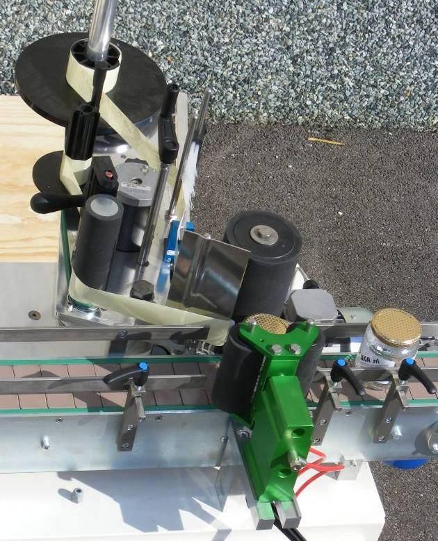
18 40 HONEY CYLINDER FOOT LINING A OR HONEY PISTON TOP LINING S (BLUE) 42 HONEY PISTON BOTTOM LINING S 5999 (WHITE) 43 OIL SCRAPER A WRM 07/ AIR PISTON LINING A DE AIR PISTON LINING A DE LINING ON HEAD DISC (12) A DE LINING ON ROTOR (2 PCS) A OR INT. LINING ON FOOT PLUG A DIM TOP LINING ON FOOT PLUG A OR CAPPING UNIT Carry out a format changeover according to the instructions supplied in section 11 FORMAT CHANGEOVER LABELLING UNIT When a jar format changeover is performed or a new label roll is loaded, the applicator must be correctly positioned, and it is necessary to make sure that the label type is compatible with the jar and adjust the jar presence and label end sensors. Before carrying out any adjustment, turn off the machine by setting the main switch located on the control panel to its OFF position (see the fig. on page 10 controls description, electric control panel). Load the label roll checking for label compatibility and orientation, bearing in mind that the rotation direction is counter-clockwise. The label roll diameter can vary between a minimum value of 76 mm and a maximum value of 250 mm. Adjustment is carried out via the centering cone. Load the roll to use according to the supplied instructions (fig. page 22): Remove the centering cone (part A) Remove the empty roll from the start plate (for replacement purposes) (part B) Remove the used paper roll from the paper collector plate (part C) Position a new label roll on the start plate Re-place the centering cone Open the tension adjustment device brush (part D) by turning the special knob control (part E) Take the leading end of a new roll and lead it through the brush (part D) and the steel column (part F) Lead it inside the photocell (part G) between the two sensors Turn right to go round the steel column (part H) until the blade edge is reached (part I) Wind more tape on the opposite side of the blade Continue until the paper driving roller is reached (part L) Manually open the paper press (part M) by using the special handle Roll round the paper driving roller (part L) in the clockwise direction Continue leading the tape to reach the paper collector plate (part C) Wind a few centimetres of the tape around the shaft (part N) of the paper collector plate Insert the fixing pin (top to bottom direction) in one of the 4 seats provided in the shaft Re-tighten the paper press (part M) Close the tension adjuster brush (part D) applying a light pressure against the steel column (part F 18 / 40


19 I H L M N C B A F D E G 19 / 40
.")
 to select label application only or label and counter-label application; then adjust the label/counter-label timer to set the time (in tenths of a second) between one label and the next.")
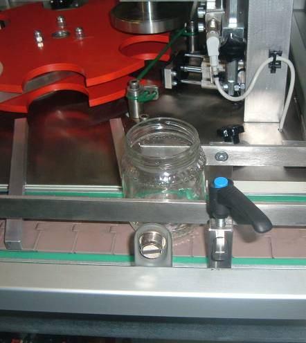
20 Align the leading end of one of the labels with the blade edge (fig.1) 1 2 Position the label detecting photocell in the empty space between two labels. The LED must remain lit (fig.2). To do this, unlock the stop located under the photocell and adjust the photocell detector to a distance of approximately 1 cm from the label leading end (the LED lights up to indicate label start). To start the labelling machine use the labelling selector control (see fig. page 8) to select label application only or label and counter-label application; then adjust the label/counter-label timer to set the time (in tenths of a second) between one label and the next. Allow the machine to complete one idle cycle (i.e. without jars). The label must stick out by a few millimeters. A minimum distance of 2 mm is recommended to allow correct lifting off the underlying paper (fig.2). Adjust the jar press device position by releasing the handwheel (fig. 3), positioning a sample jar as shown in fig. 4 and checking that the distance between the two jar pressing rollers and the jar is between 5 and 10 mm. Adjust the jar guiding sideboard to a distance of approximately 3 mm from the jar to process by using the special adjustment handwheels (fig. 5). 20 / 40


21 5-10mm / 40

. 2.")

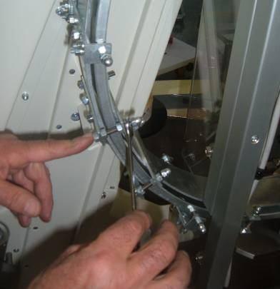
22 11.0 FORMAT CHANGEOVER The machine is supplied equipped with one starwheel (to be chosen by the customer). Additional starwheels can be supplied separately. Minimum jar dimensions: height: 8 cm diameter: 5,5 cm weight: 250 g Maximum jar dimensions: height: 14 cm diameter: 9 cm weight: 1000 g To change to jar dimensions different from the original dimensions, carry out the operations described in section 5.1 JAR FORMAT CHANGEOVER JAR FORMAT CHANGEOVER 1. Turn off the machine by setting the main switch in the electric control panel to its OFF position (see fig. page 10 controls description, control panel). 2. De-activate the main air supply valve by holding down the button. 3. Rotate the jar ejector until it is led out of the starwheel. 4. Remove the starwheel by loosening the centre knob in the wheel top part. Replace with another starwheel model and re-tighten the centre knob. 5. After replacing the starwheel, adjust the position of the microswitch under the wheel so that it is pressed by the jars as they are fed in. Make sure that the microswitch is flush with the starwheel: the incoming jars must make contact to both the microswitch and the starwheel at the same time. 6. Move the capping unit so that the centring disk can be removed. 7. Loosen the knob to remove the cap stop. 8. (7-8) Empty all the caps from the guide and remove the installed PVC adapter. Replace it with another one suitable for the new format. 9. Replace the centring disc. 10. Adjust the green cap guide by turning the screws highlighted in the figure. 11. (11-12) Pull back the guide to let a jar through. 13. ( ) Adjust the jar feeding guides and the labelling machine presser / 40


23 18. (17-18) It may be necessary to adjust the cap in-feed guide as shown in the figure, according to the cap thickness and width, and the guide conveying the caps on to the chute (fig.) by turning the two screws highlighted in the photo. By moving the screws to the top holes, it will be possible to use a larger cap. The hole design will be agreed with the customer in advance according to special requirements / 40


24 / 40


25 / 40
26 HONEYPACK WIRING DIAGRAMS 26 / 40
27 27 / 40
28 28 / 40
29 29 / 40
30 30 / 40
31 31 / 40
32 32 / 40
33 33 / 40
34 34 / 40
35 35 / 40
36 LABELLING MACHINE WIRING DIAGRAMS 36 / 40
37 37 / 40
38 38 / 40

39 39 / 40

40 24 MONTHS WARRANTY The machinery is guaranteed 24 MONTHS starting from the date of sale. The guarantee is only valid if, when the machine is collected by our customer care or technical service staff, the owner can produce proof of purchase in the form of a fiscal receipt or invoice. The guarantee includes free-of-charge repairing and replacement of any part of the machinery that is found to have manufacturing or material defects by the manufacturer or the manufacturer s authorised person. This guarantee shall not apply to damages caused by negligence, misuse or use not in compliance with the directions contained in the instruction manual, as well as in case of accidents, alteration, tampering, wrong repairing or repairing with non-original parts, repairing by persons not authorised by Lega s.r.l. and damages during transport to/from the purchaser s. All electric parts (electric motors, controls etc.) and parts exposed to normal wear and tear as well as aesthetic parts are also not covered by the guarantee. All labour, packing, forwarding and transport charges shall be borne by the purchaser. Any defective parts which have been replaced shall be retained by and become the property of LEGA S.R.L. Any breakdown or defect which should occur during the guarantee period or after its last date shall not in any case entitle the purchaser to suspend the payments nor to any discount off the price of the machine. In any case, Lega s.r.l. shall not be held responsible for any damages resulting from the incorrect use of the machinery. Declaration of conformity LEGA srl - Costruzioni Apistiche with head office in Faenza Italy, Via Maestri del Lavoro 23, declare under our sole responsibility that the products to which this declaration relates are in conformity with Directive 2006/42/EC. Furthermore LEGA SRL declares food, hygienic and safety conformity of the materials used to produce the spare parts of these products that keep in contact with food, with accordance with DM 21/03/1973, artt (as modified from last DM n. 258 of 21/12/2010), with Commission Regulation 1935/2004/CE and EU 10/ / 40
Technical Data. Name: ERIKA Automat fully automatic machine to divide and to round dough pieces of the same size
 AUTOMAT MANUAL 1 Technical Data Name: ERIKA Automat fully automatic machine to divide and to round dough pieces of the same size Type Divisions Dough Portions (in ounces) Plate Nos. 3 30 1.0 3.5 #35 4/40A
Cleaning unit for coolant. :_decftez`_>r_fr] Book No.: V2
![Cleaning unit for coolant. :_decftez`_>r_fr] Book No.: V2](/thumbs/90/104143238.jpg "Cleaning unit for coolant. :_decftez`_>r_fr] Book No.: V2") Cleaning unit for coolant :_decftez`_>r_fr] Book No.: 1271526-02 V2 Alfa Laval Separation AB Separator Manuals, dept. SKEL S-147 80 Tumba, Sweden Telephone: +46 8 53 06 50 00 Telefax: +46 8 53 03 10 40
Cleaning unit for coolant :_decftez`_>r_fr] Book No.: 1271526-02 V2 Alfa Laval Separation AB Separator Manuals, dept. SKEL S-147 80 Tumba, Sweden Telephone: +46 8 53 06 50 00 Telefax: +46 8 53 03 10 40
541D19 SERIES. Technical Manual. A Division of Aquion Partners L.P.
 541D19 SERIES Technical Manual A Division of Aquion Partners L.P. Table of Contents Introduction... Page 1 Technical Specifications... Page 2 Flow Diagrams... Page 3 Injector & Flow Control Selection Injector...
CONTENTS 1 INTRODUCTION 3 2 PRODUCT DESCRIPTION 4 3 GENERAL INFORMATION 5 4 INSTALLATION 6 5 USE 10 6 MAINTENANCE 12 REV.
 CONTENTS 1 INTRODUCTION 3 2 PRODUCT DESCRIPTION 4 3 GENERAL INFORMATION 5 4 INSTALLATION 6 5 USE 10 6 MAINTENANCE 12 REV. 01 2 / 12 CHAPTER 1 - INTRODUCTION Thank you for purchasing a product from the
CONDITIONS OF SALE AND WARRANTY
 M.E.P. Mbl 100 Monoblock - Operator s handbook CONDITIONS OF SALE AND WARRANTY 1. Read carefully this operator's handbook before operating our Mbl 100 Monoblock. 2. M.E.P. guarantees his Mbl 100 Monoblock
HD Kompakt Service Manual
 HD Kompakt Service Manual English 5.906-583.0 Rev. 00 (08/13) 1 1 Contents 1 Contents.................................................... 2 2 Preface.....................................................
Carmen. Operating Instructions. 1
 Carmen Operating Instructions Streamline Supplies 9 Joseph Baldwin Place, Shepparton Victoria Ph: Fax: www.streamlinesupplies.com.au Introduction Please read this technical handbook carefully since it
MAINTENANCE MANUAL TAIYO SEIKI CO., LTD.
 MAINTENANCE MANUAL TAIYO SEIKI CO., LTD. Introduction This Maintenance Manual explains how to replace and adjust the major components of the Automatic Taping Machine when required in daily operation.
ENGINEER S MANUAL No.01
 1-NEEDLE, UNISON FEED, LOCKSTITCH MACHINE (AUTOMATIC LUBRICATION) LU-1510 1-NEEDLE, UNISON FEED, LOCKSTITCH MACHINE WITH AUTOMATIC THREAD TRIMMER (AUTOMATIC LUBRICATION) LU-1510-7 1-NEEDLE, UNISON FEED,
PS-2/ES Automated pack & tag machine with IndES fastening system
 English Manual PS-2/ES Automated pack & tag machine with IndES fastening system Contents 1. Introduction 2. Important Safety Instructions 3. PS-2/ES 4. Unpacking the machine 5. Setting up the machine 6
SOP: LFA SOP For Automatic Capsule Filling Machine
 SOP For Automatic Capsule Filling Machine Alastair Sanderson 31/08/16 1 Objective To provide the operating procedure for Automatic Capsule Filling Machine. 2 Scope Includes the operating procedure for
MC2000 OPERATING AND CALIBRATION INSTRUCTIONS
 MC2000 OPERATING AND CALIBRATION INSTRUCTIONS CONTENTS 1 - CERTIFICATE OF CONFORMITY... 3 2 - PRESENTATION... 4 2. 1 - GENERAL... 4 2. 2 - CHARACTERISTICS... 4 2. 3 - OPERATING PRINCIPLE... 5 2. 3. 1 -
Tornado Operations & Maintenance Manual
 TORNADO INDUSTRIES 7401 W. LAWRENCE AVENUE CHICAGO, IL 60706 (708) 867-5100 FAX (708) 867-6968 www.tornadovac.com Tornado Operations & Maintenance Manual MODEL NO. 99690 BD 22/14, 99720 BD 26/14 L9722
OTO BONDER OWNER S MANUAL WITH CIRCULATING SYSTEM MACHINERY DIVISION - - L to R Unit Shown
 GBAC RROTO OTO BONDER BONDER WITH CIRCULATING SYSTEM G B MACHINERY DIVISION OWNER S MANUAL L to R Unit Shown - - IMPORTANT FOREWORD 1) To ensure efficiency, the GBAC must be properly maintained. Carefully
IMCE-250 EXTRUSION LINE MACHINE
 IMCE-250 EXTRUSION LINE MACHINE INTERNATIONAL MACHINE CONCEPTS WELCOMES YOU TO YOUR NEW MACHINE Operation Manual: Date 2017 CONTENTS Chapter 1 Machine Description 1.1 Uncrating Instructions 1.2 Installation
Part 2: Installation Instructions cl
 Contents Page: Part 2: Installation Instructions cl. 381-382 1. Delivery scope............................... 3 2. General and Transportation safety precautions........... 3 3. Stand installation 3.1 Installing
Swaging Machine Type H50-46ECO
 ENDEAVOUR Int. Ltd. Tel +44 (0) 1225 446770 Fax +44 (0) 1225 446775 USER MANUAL Swaging Machine Type H50-46ECO Website: www.hydralok.net CONTENTS WARRANTY CONDITIONS... 3 EC DECLARATION OF CONFORMITY...
USE AND MAINTENANCE MANUAL AUTOMATIC DIVIDER
 USE AND MAINTENANCE MANUAL AUTOMATIC DIVIDER Page 2 CONTENT 1 - GENERAL 2 - PRODUCT INFORMATION 2.1 VOLTAGES 2.2 POSSIBLE VERSIONS 2.3 MATERIALS USED 3 - PRODUCT CONCEPTS 3.1 WARNINGS 3.2 DESCRIPTION OF
PLC-1700 Series PLC-1710, , 1760, , 1760L
 Post-bed, Unison-feed, Lockstitch Machine PLC-1700 Series PLC-1710, 1710-7, 1760, 1760-7, 1760L ENGINEER S MANUAL 40040656 No.E372-00 Introduction This Engineer s Manual is for technical service engineers.
Installation and Operating Instructions DÜRR Regeneration Unit for X-ray developers XR 24, XR24 II, XR 24 Nova, XR 24 Pro
 Installation and Operating Instructions DÜRR Regeneration Unit for X-ray developers XR 24, XR24 II, XR 24 Nova, XR 24 Pro 2006/01 Content Important Information 1. Notes... 3 1.1 CE - Labeling... 3 1.2
Operation Manual 322 KL
 Operation Manual 322 KL 8/07 von Oertzen GmbH Ferdinand-Harten-Str. 10 22949 Ammersbek Tel. +49 40 604110 Fax +49 40 6041149 www.oertzen-gmbh.de info@oertzen-gmbh.de Table of Content 1. Introduction Page
The Danger signal indicates an immediately hazardous situation which, if not avoided, will result in death or serious injury.
 The Danger signal indicates an immediately hazardous situation which, if not avoided, will result in death or serious injury. The Warning signal alerts you to potential hazards or unsafe practices which,
OPERATING AND SETTING MANUAL
 COMPLETE SOLUTIONS FOR ON-DEMAND CD AND DVD PRODUCTION Speed Wrap Case Wrapper for CD or DVD Cases OPERATING AND SETTING MANUAL TP 000 156-1 - Thank you for purchasing a JMV Robotique Speed Wrap OPERATING
DOCUMENT CREASING MACHINE
 DOCUMENT CREASING MACHINE OPERATORS MANUAL Morgana Systems Limited Snowdon Drive Winterhill Milton Keynes Buckinghamshire MK6 1AP United Kingdom Telephone: ( 01908 ) 608888 Facsimile: ( 01908 ) 692399
Operator Manual AUTOMATIC BUN DIVIDER ROUNDERS
 Operator Manual AUTOMATIC BUN DIVIDER ROUNDERS Pagina 2 CONTENT 1 - GENERAL 2 - PRODUCT INFORMATION 2.1 VOLTAGES 2.2 POSSIBLE VERSIONS 2.3 MATERIALS USED 3 - PRODUCT CONCEPTS 3.1 WARNINGS 3.2 DESCRIPTION
TQ Series. Electronic Control Pump Instruction Manual. 50Hz. ISO 9001 Certified Walrus Pump Co., Ltd.
 TQ Series Electronic Control Pump Instruction Manual 50Hz ISO 9001 Certified Walrus Pump Co., Ltd. EC Declaration of Conformity Manufacturer: Walrus Pump Co., Ltd. Address: No. 83-14, Dapiantou, Sanjhih
Bliss Box Former Troubleshooting. 6.1 Troubleshooting Chart. Troubleshooting INTRODUCTION SAFETY PROCEDURES
 6.0 Bliss Box Former 1.0 INTRODUCTION Table 6-1 provides a logical sequence of tests that are designed to isolate problems with the Bliss Box Former machines. This table includes a list of probable causes
Parts and Service Manual
 Section II Parts and Service Manual (70241A) CLARKE TECHNOLOGY Operator's Manual - MINI MAX Page -29- Frame and Front Cover Assembly Drawing 2/01 Page -30- CLARKE TECHNOLOGY Operator's Manual -MINI MAX
Glass and Dishwashers AMX / AUX Series
 Glass and Dishwashers AMX / AUX Series INSTALLATION OPERATION REV. 8.xx 04.07.2005 Installation and Operation Instructions for Models of AMX / AUX Series Content Page 1 Installation... 3 2 Connections...
Instruction Manual - Anti-Siphon Ejector Chlorine & Sulfur Dioxide 500 PPD (10 kg/h) Maximum Capacity
 Maximum Capacity") - Anti-Siphon Ejector Chlorine & Sulfur Dioxide 500 PPD (10 kg/h) Maximum Capacity 100 PPD (2 kg/h) Chlorine or Sulfur Dioxide 250 & 500 PPD (5 & 10 kg/h) Chlorine or Sulfur Dioxide Anti-Siphon Ejector
- Anti-Siphon Ejector Chlorine & Sulfur Dioxide 500 PPD (10 kg/h) Maximum Capacity 100 PPD (2 kg/h) Chlorine or Sulfur Dioxide 250 & 500 PPD (5 & 10 kg/h) Chlorine or Sulfur Dioxide Anti-Siphon Ejector
EVAC Commercial Marine Equipment TOILET TECHNICAL DATA EVAC 90, SQUATTING TOILET. To main vacuum line, connection Ø50.
 Date: 25 Jan 2005 Doc. 1:114E TECHNICAL DATA 5979301 EVAC 90, SQUATTING To main vacuum line, connection Ø50 Service door 600 Push button Fresh water supply connection 1/2" MPT BSP 700 700 Flushing mechanism
KITCHEN EXHAUST FAN GLEC-6 INSTALLATION AND MAINTENANCE
 KITCHEN EXHAUST FAN GLEC-6 INSTALLATION AND MAINTENANCE 2 GLEC-6 - Installation and maintenance CONTENTS 1 Important information... 3 2 Safety notes... 3 3 Technical description...4 4 Transport... 6 5
Bottle Height Adjustment Bottle Diameter Adjustment Cork Length Adjustment Cork Depth Adjustment
 P55 Champagne Corker Setup and Maintenance Read this carefully before operating the corker. One person should be assigned to maintain the corker. Only this primary operator should make adjustments to the
AUTOMATIC SLICING MACHINE
 AUTOMATIC SLICING MACHINE Instruction for use and maintenance Noaw s.r.l. Via Colombera, 27 21048 Solbiate Arno (VA) Tel. +39 0331 219 723 - fax. +39 0331 216 197 e-mail: noaw@noaw.it http://www.noaw.it
CONDITIONS OF SALE AND WARRANTY
 CONDITIONS OF SALE AND WARRANTY 1. Read carefully this operator's handbook before operating our G300 wire-hooder. 2. M.E.P. guarantees his G300 wire-hooder in case of breakages caused by faulty components
Installation and Maintenance Novax Smoke Exhaust Fan Type ACN Smoke
 918149-0 GB Installation and Maintenance Novax Smoke Exhaust Fan Type ACN Smoke 1. Application 2. Handling 2.1 Marking 2.2 Weight 2.3 Transport 3. Storage 4. Installation 4.1 Prior to attachment 4.2 Attachment
hp Dust Collector With Vacuum Attachment
 Please dispose of packaging for the product in a responsible manner. It is suitable for recycling. Help to protect the environment, take the packaging to the local amenity tip and place into the appropriate
DA-9270 TWIN NEEDLE (THREE NEEDLE) FEED OFF THE ARM DOUBLE CHAIN STITCHER. English
 FEED OFF THE ARM DOUBLE CHAIN STITCHER. English") TWIN NEEDLE (THREE NEEDLE) FEED OFF THE ARM DOUBLE CHAIN STITCHER English Thank you very much for buying a BROTHER sewing machine. Before using your new machine, please read the safety instructions below
TWIN NEEDLE (THREE NEEDLE) FEED OFF THE ARM DOUBLE CHAIN STITCHER English Thank you very much for buying a BROTHER sewing machine. Before using your new machine, please read the safety instructions below
B.I.C.A Built-In Coffee Appliance
 B.I.C.A Built-In Coffee Appliance Automatic Coffee Brewer Parts & Service Models: 1033510, 1033510S & 1033511 3828 S. Main St. Los Angeles, CA 90037-1491 800-421-6860 310-787-5444 Fax 310-787-5412 e-mail:
CUTMASTER Strip Cutting Machine
 EASTMAN THE EASTMAN CUTMASTER Strip Cutting Machine WARNING Safety glasses must be worn at all times when operating or servicing this equipment. Instruction Manual & Illustrated Parts List Please read
Please read operating instructions carefully before use and keep it for further reference.
 GB OPERATING INSTRUCTIONS Automatic hot-air welding machine Please read operating instructions carefully before use and keep it for further reference. APPLICATION Overlap and tape welding of coated fabric
SPECIFICATIONS FEATURES
 FEATURES Excellent for collecting the large chips which will drop into the garbage can before reaching the impeller. The filter bag filters out the remaining sawdust down to 5 microns. With the cyclone
ST1. Mod. USE AND MAINTENANCE MANUAL
 Mod. USE AND MAINTENANCE MANUAL 2 Use and Maintenance Manual ---------------------------------------------------------------------------------------------------------------------------------------------------------------------------------
GLEB Kitchen exhaust fan
 GLEB Kitchen exhaust fan Installation and Maintenance??.1.2013 Contents 1. Important information 2. Safety notes 3. Technical description 4. Transport 5. Mounting instructions 6. Commissioning 7. Maintenance
MOULD WITH ENTERING PUNCHES
 SACMI MOLDS&DIES MOULD WITH ENTERING PUNCHES INSTRUCTION MANUAL 1-1 GENERAL WARNING This manual is part and parcel of the product. Carefully read the instructions of the manual as they give important information
OPERATING MANUAL Gfp 255C Please read this manual carefully before operating!
 OPERATING MANUAL Gfp 255C Please read this manual carefully before operating! Unpacking, assembly, and operating videos are available at www.gfpsmoothstart.com 1 Table of Contents Gfp 255C March 2015 Contents
Hakki Pilke Raven spare parts manual
 1 ENGLISH Hakki Pilke Raven spare parts manual Valimotie 1, FI-85800 Haapajärvi, FINLAND Tel. +358 8 772 7300, Fax +358 8 772 732 info@maaselankone.fi, www.maaselankone.fi 2 Table of contents 1 Upper section
USER S MANUAL ATH WH220
 USER S MANUAL ATH WH220 INDEX INTRODUCTION... - 3 - General information s... - 3 - Description of pneumatic jack... - 4 - Operation of jack... - 5 - Technical data... - 6 - Dimension drawing... - 6 - INSTALLATION...
OPERATION AND MONTAGE MANUAL ROOF FANS
 NO RFEC/U/2017-1 (EN) (valid since 18.08.2017) ROOF FANS RF/EC...-... / RFV/EC...-... Venture Industries Sp. z o.o. is not responsible for any damage caused by improper use of the fan and reserves the
EHA Hoffmann International GmbH
 EHA Hoffmann International GmbH User manual EHA-TRANSPRINT HP 2020 Machine-No.: Year: EHA Hoffmann International GmbH Michelsbergstraße 24 D-57080 Siegen/Germany Telephone: +49 271 39 32-0 Telefax: +49
BL Series INSTRUCTIONS
 BL Series Models: EX5204/BL514 EX5204/BL515 EX5214/BL524 EX5214/BL525 EXT5214/BL524 EXT5214/BL525 EX5404/BL614 EX5404/BL615 EX5414/BL624 EX5414/BL625 EXT5214H/BL528 EXT5214H/BL529 Automatic Backlatcher
52 CEILING FAN. Owner s Manual Models #50336, 50337
 52 CEILING FAN Owner s Manual Models #50336, 50337 If a problem cannot be remedied or you are experiencing difficulty in installation, please contact the Service Department: 1-877-706-3267, 9 a.m.- 5 p.m.
HOT 4000 USER MANUAL. Version 2.1. This manual shall be read in its entirety before using the machine.
 HOT 4000 USER MANUAL Version. This manual shall be read in its entirety before using the machine. IMPORTANT SAFETY INSTRUCTIONS When using Hot 4000, basic precautions should always be taken, including
OPERATING & MAINTENANCE MANUAL INDUSTRIAL DIRECT FIRED DIESEL/KEROSENE HEATERS IC 25
 OPERATING & MAINTENANCE MANUAL INDUSTRIAL DIRECT FIRED DIESEL/KEROSENE HEATERS IC 25 NOT FOR DOMESTIC USE SPACE HEATING ONLY Made By: Spitwater Australia Pty Ltd 953 Metry St North Albury, NSW, Australia
This label warns for risk of electrical shock when failing to observe.
 MANUAL horizontal centrifugal pumps MB series ic drive SB series mechanical seal 1. Introduction 2. Safety precautions 3. Receipt 4. Installation / Operation and Maintenance 4.1 Installation 4.2 Operation
Tempest TP420/180 Electric Pressure Washer
 Please dispose of packaging for the product in a responsible manner. It is suitable for recycling. Help to protect the environment, take the packaging to the local amenity tip and place into the appropriate
Waste water ejection unit
 Waste water ejection unit Over ground box SWH 500/50-80 SWH 500/50-80 Operation manual Table of contents: Page Declaration of conformity... 3 1. General... 4 1.1 Introduction... 4 1.2 Enquiries and orders...
Please read this manual before using the machine. Please keep this manual within easy reach for quick reference.
 DA-927A DA-928A INSTRUCTION MANUAL Please read this manual before using the machine. Please keep this manual within easy reach for quick reference. TWIN NEEDLE / THREE NEEDLE FEED OFF THE ARM DOUBLE CHAIN
VC10LPH with HEPA Filter & Disposable Dust Bag
 Instruction Manual HOUSEMAID 10 Litre Plastic Dry Vacuum Cleaner Models: VC10LP with Cloth Filter only VC10LPH with HEPA Filter & Disposable Dust Bag Please read this Instruction Manual carefully and follow
Los Angeles Abrasion Machine HM-70A & HM-70AF
 Operating Manual Los Angeles Abrasion Machine HM-70A & HM-70AF Rev: 07/24/2018 PHONE: 800-444-1508 740-548-7298 P.O. Box 200, Lewis Center, Ohio 43035-0200 E-mail: customerservice@gilsonco.com Website:
OPERATION MANUAL KP4041 POLY SCRAP COMPACTOR
 OPERATION MANUAL KP4041 POLY SCRAP COMPACTOR IBIS INTERNATIONAL Thank you for purchasing the KP4041 Poly Scrap Compactor. IBIS appreciates your confidence in our product, and promises to support its operation
INDEX I.- FINAL TEST FOR PRODUCT SAFETY 3 II.- REPLACEMENT PROCEDURES 3 III.- TROUBLE SHOOTING CHART 5 IV.- WIRING DIAGRAM 6 V.- ELECTRICAL RATING 6
 INDEX I.- FINAL TEST FOR PRODUCT SAFETY 3 II.- REPLACEMENT PROCEDURES 3 III.- TROUBLE SHOOTING CHART 5 IV.- WIRING DIAGRAM 6 V.- ELECTRICAL RATING 6 VI.- EXTERNAL PARTS FOR UPRIGHT VACUUM CLEANER PARTS
Parenzo Range. Basin Mixer, Bath Filler & Bath Shower Mixer. Assembly instructions
 Parenzo Range Basin Mixer, Bath Filler & Bath Shower Mixer Assembly instructions We have designed these products with your enjoyment in mind. To ensure that they work to their full potential, they need
HEDMAN The HEDMAN Company 189 Gordon St. Elk Grove Village, IL
 HEDMAN The HEDMAN Company 189 Gordon St. Elk Grove Village, IL 60007 800-872-2788 NOTICE Proprietary Information - this material is not to be reproduced by any means or disclosed in any way without prior
TACH-IT MODEL #3568 SEMI-AUTOMATIC TWIST TIE MACHINE OPERATION MANUAL AND PARTS LIST
 TACH-IT MODEL #3568 SEMI-AUTOMATIC TWIST TIE MACHINE OPERATION MANUAL AND PARTS LIST 1 TABLE OF CONTENTS: SECTION 1 CAUTION PAGE 3 SECTION 2 PARTS IDENTIFICATION PAGE 4 SECTION 3 MACHINE DIMENSIONS AND
INSTRUCTION MANUAL FOR DUTCHESS MODEL 260 BAGEL & BUN SLICER
 INSTRUCTION MANUAL FOR DUTCHESS MODEL 260 BAGEL & BUN SLICER Table of Contents Safety Information I thru VII Uncrating Instructions 1 Introduction 2 Adjustment Instructions 3 Operating Instructions, Cleaning,
EYS SEPARATOR EYS 01 G. USER MANUAL for EYS SCREW-PRESS SEPARATOR MODEL EYS 01 G. User Manual for EYS 01G Screw-Press Separator
 USER MANUAL for EYS SCREW-PRESS SEPARATOR MODEL EYS 01 G User Manual for EYS 01G Screw-Press Separator Table of Contents Page 1. Introduction 2 2. General Safety Instructions 3 3. Installation 5 4. Start-up
ACN SMOKE INSTALLATION AND MAINTENANCE
 NovAx ACN SMOKE INSTALLATION AND MAINTENANCE 918149-0 English 918149-0 GB Installation and maintenance NovAx smoke exhaust fan type ACN smoke 1. Application 2. Handling 2.1 Marking 2.2 Weight 2.3 Transport
Ceiling Sweep Fan Assembly Instructions
 Ceiling Sweep Fan Assembly Instructions CSF Series Installation Note: This fan must be installed by a licenced electrical contractor Improperly installed ceiling sweep fans can be dangerous and expensive
Dynapac Chip Spreader is an accessory that enables the spreading of stone chippings, gravel or other similiar granulates in conjunction with the
 Accessories Manual (E2022) Operation & Maintenance Dynapac Chip spreader CC224HF - CC334HF CC2200 - CC3300 CG2300 Dynapac Chip Spreader is an accessory that enables the spreading of stone chippings, gravel
USER MANUAL JASOPELS SOFT BRUSH ITEM NO Our quality Your choice
 USER MANUAL JASOPELS SOFT BRUSH ITEM NO. 31400001 Our quality Your choice 2 www.jasopels.com TABLE OF CONTENTS 1. Preface...3 2. Declaration of Conformity...5 3. Symbol explanation...6 4. Introduction
CP-200 Push Button. CP Warewash Pump Instruction & Operation Manual Push Button , Rev1.0,
 CP-200 - Warewash Pump Instruction & Operation Manual Push Button 20-08881-01, Rev1.0, 25.06.2012, Page 1 of 8 Contents A) Description B) Site Survey and Installation Requirements C) Package Contents D)
ILLUSTRATIONS ARE FOR REFERENCE ONLY AND ARE SUBJECT TO CHANGE WITHOUT NOTICE ITEM P/N DESCRIPTION
 TC-0 TURN PLATE TC-0 TURN PLATE 0 0 0 TC-0-000 TURNTABLE TC-0-00 TURNTABLE, TC-0 TC-0-00 SCREW, M X TC-0-00 COVER, TC-0 TC-0-00 RETAINING PIN TC-0-00 CLAMP TC-0-00 CLAMP SEAT TC-0-0 CLAMP SEAT, TC-0 TC-0-00
CHIPPER PC1 INSTRUCTIONS FOR INSTALLATION OPERATION AND MAINTENANCE. Series 35
 Cl/SfB (73.4) X CHIPPER PC1 INSTRUCTIONS FOR INSTALLATION OPERATION AND MAINTENANCE Series 35 Imperial Machine Company (Peelers) Limited Harvey Road, Croxley Green, Herts WD3 3AX, England Telephone: 01923
FLAME115 INFRARED HEATER SERVICE MANUAL INDEX FIRE 115 WARNING
 FLAME115 INFRARED HEATER SERVICE MANUAL INDEX 1. CONTROLS AND COMPONENTS 2. FLAME CONTROL CYCLES 3. MAINTENANCE SCHEDULE 4. TROUBLESHOOTING GUIDE 5. REPAIR PROCEDURES 1. FAN MOTOR ASSEMBLY 2. FUEL FILTER
3800 North Mill Road Vineland, NJ USA Tel: Fax: Web: Rev. A
 Versa-Roll Roller Apparatus - Modular CLS-3857 OPERATIONS MANUAL 3800 North Mill Road Vineland, NJ 08360 USA Tel: 1-800-843-1794 Fax: 1-800-922-4361 Web: www.cglifesciences.com Rev. A Contents: General
USER GUIDE. DRENA 2 - User Manual ELECTRICAL PANEL FOR 2 MOTORS - WASTE WATER -
 USER GUIDE DRENA 2 - User Manual ELECTRICAL PANEL FOR 2 MOTORS - WASTE WATER - II CONTENTS 1. SYMBOLS AND WARNINGS... 5 2. GENERAL INFORMATION... 6 3. WARNINGS... 7 4. GENERAL DESCRIPTION... 8 5. INSTALLATION...
VARIABLE SPEED GRINDER OWNER S MANUAL R MANUAL VERSION SERIAL #
 R3.5 VARIABLE SPEED GRINDER SERIAL # MANUAL VERSION CONFORMS TO UL STD 763, NSF/ANSI STD 8 CERTIFIED TO CSA STD C22.2 #95 CONFORMS TO CE, IEC TESTED 2. Introduction WARNING: To limit risk of personal injury
INSTALLATION, OPERATION & MAINTENANCE MANUAL
 CENTRAL FANS COLASIT LTD Unit 12A, Palmers Road, East Moons Moat, Redditch. Worcs. B98 0RF Tel: 01527-517200 Fax: 01527-517195 Edition 04_13 INSTALLATION, OPERATION & MAINTENANCE MANUAL CIV Fan Range Valid
Installation Instructions Part No , Part No Part No
 Torsion-Flex Motor mount for PSC motors and Rigid-Mount for ECM motors Replacement Kit Cancels: New Installation Instructions Part No. 327752-401, Part No. 327753-401 Part No. 327754-401 IIK-310A-45-11
USE AND INSTALLATION HANDBOOK
 Date : 30/10/14 Rev. 02 PR.T : FG006203 USE AND INSTALLATION HANDBOOK (SLA1) ALARM1, ALARM2 ALARM WITH BUFFER BATTERY Via Enrico Fermi, 8-35020 Polverara PD Tel.049/9772407 Fax.049/9772289 www.fourgroup.it
Compression Sprayers CLEANER 3275PP, 3270PP, 3275PE, 3270PE PROFI PLUS 3275P, 3270P PROFI PLUS 3275P, 3270P TECH DATA SHEET /03/17
 0/0/ TECH DATA SHEET 0 Compression Sprayers Ersatzteile Spare Parts Pièces de Rechange Reserve-onderdelen Piezas de repuesto Pezzi di ricambio Peças sobressalentes Varaosat Reservdelar Reservdeler Reservedele
Sanitise Syrup Lines & Valves. Taylor PH61 Cleaning every 14 days
 Taylor PH61 Cleaning every 14 days Drain the Syrup Lines Remove each syrup feed tube from syrup bottle and let excess syrup drain from the feed tube back into the syrup bottle. When flow of syrup from
Altra Series Dampener
 Crestline TM Altra Series Dampener Installation Instructions Heidelberg MO X88-66 10/97 Rev-A GENERAL INFORMATION ATTENTION CRESTLINE ALTRA SERIES TM DAMPENER OWNER! Accel Graphic Systems provides parts
User Manual GV25 GV35 GV702. Company information: Original instructions GV12066 (1)
") User Manual Original instructions GV25 GV35 GV702 Company information: www.vipercleaning.eu info-eu@vipercleaning.com GV12066 (1) 2012-04-10 USER MANUAL ENGLISH TABLE OF CONTENTS Introduction... 4 Manual
User Manual Original instructions GV25 GV35 GV702 Company information: www.vipercleaning.eu info-eu@vipercleaning.com GV12066 (1) 2012-04-10 USER MANUAL ENGLISH TABLE OF CONTENTS Introduction... 4 Manual
Hydraulic crimping tool. HO-16 Art QZERTIFIKAT DIN EN ISO convincing solutions
 Hydraulic crimping tools INSTRUCTION MANUAL Hydraulic crimping tool HO-16 Art. 216802 DIN EN ISO 9001 QZERTIFIKAT 1. Technical data Area of application: For the creation of an electrical connection by
IMPORTANT SAFETY INSTRUCTIONS
 CONTENTS 1.SPECIFICATIONS... 1 2.INSTALLATION... 1 3.INSTALLATION OF THE SYNCHRONIZER... 2 4.ASSEMBLY OF HAND WHEEL... 2 5.INSTALLATION OF HAND WHEEL... 2 6.INSTALLING THE BELT COVER... 3 7.ADJUSTING THE
Part 3: Service manual, class
 Contents Page: Part : Service manual, class 7-75. General.................................................. Gauges................................................. 4. Description and adjustment of the
FORMATIC Instruction Manual
 FORMATIC Instruction Manual Gibson Street, Leeds Road, Bradford West Yorkshire, England. BD3 9TR Telephone: +44 (0) 1274 668771 Fax: +44 (0) 1274 665214 FORMATIC CONTENTS 1. Introduction 2. Technical Specification
Glass and Dishwashers AMX / AUX Series
 Glass and Dishwashers AMX / AUX Series INSTALLATION OPERATION VERSION 24.02.04 Important Notes Use in Accordance with Regulations This machine is exclusively to be used to wash ware such as plates, cups,
OPERATION AND MONTAGE MANUAL ROOF FANS
 NO RF/U/2017 (ENGLISH) (valid since 13.10.2017) ROOF FANS RF / RFV Venture Industries Sp. z o.o. is not responsible for any damage caused by improper use of the fan and reserves the right to modify this
Technical Data TYPE T14 & T14D TEMPERATURE PILOT SPENCE ENGINEERING COMPANY, INC. 150 COLDENHAM ROAD, WALDEN, NY SD 4511A T14 PILOT
 Technical Data SD 4511A SPENCE ENGINEERING COMPANY, INC. 150 COLDENHAM ROAD, WALDEN, NY 12586-2035 TYPE T14 & T14D TEMPERATURE PILOT PRINTED IN U.S.A. SD 4511A/9811 5 13 /16 D 4 7 /8 1 13 /16 T14 PILOT
SASE BULL 240C. Dust Collection System Manual
 SASE BULL 240C Dust Collection System Manual www.sasecompany.com 800.522.2606 sales@sasecompany.com Contents 2 Symbols 3 Safety Instructions 3 Intended Use 4 Design of the Bull 240 5 Product Description
OPERATING MANUAL. BAK Thermoplastic Welding Technology AG 1
 OPERATING MANUAL BAK Thermoplastic Welding Technology AG 1 SAFETY Danger to life Unplug the tool before opening it as live components and connections are exposed. Danger of fire and explosion in case of
EQUIPMENT MANUAL FOR ES25 PASS THROUGH DISHWASHER
 EQUIPMENT MANUAL FOR ES25 PASS THROUGH DISHWASHER JUNE 2011 TABLE OF CONTENTS 1. Important: Prior to Installation 3 2. General Description 4 3. Technical Specifications 5 4. Installation 6 5. Initial Start-up
CONTENTS 1. SPECIFICATIONS SET-UP FOR THE OPERATOR MAINTENANCE... 34
 ENGLISH ii CONTENTS. SPECIFICATIONS... 2. SET-UP.... Installing the motor unit... 2. Installing the control box... 3. Installing the belt... 2 4. Adjusting the pulley cover... 2 5. Installation and adjustment
RTP9 ROTARY TABLET PRESS USER MANUAL
 RTP9 ROTARY TABLET PRESS USER MANUAL LFA Tablet Presses is a trading name of LFA Machines Oxford LTD All of the content in this document is covered by copyright CONTENTS Page 1. Introduction Page 1. Technical
Installation and Operation Manual For Hunter Ceiling Fans
 Installation and Operation Manual For Hunter Ceiling Fans 1 2 CONGRATULATIONS! Your new Hunter ceiling fan is an addition to your home or office that will provide comfort and performance for many years.
Chapter 3 Cooling, heating and ventilation systems
 3 1 Chapter 3 Cooling, heating and ventilation systems Contents Antifreeze mixture..............................see Chapter 1 Cooling fan assembly - testing, removal and refitting.............8 Cooling
Grinding mill MISTRAL 50L (art. 650P)
") Grinding mill MISTRAL 50L (art. 650P) USE AND MAINTENANCE MANUAL RIVER SYSTEMS SRL Via Marco Polo, 33-35011 Campodarsego (Padova) Italy Tel. +39-049-9202464 - Fax: +39-049-9216057 - e-mail: info@riversystems.it
Grinding mill MISTRAL 50L (art. 650P) USE AND MAINTENANCE MANUAL RIVER SYSTEMS SRL Via Marco Polo, 33-35011 Campodarsego (Padova) Italy Tel. +39-049-9202464 - Fax: +39-049-9216057 - e-mail: info@riversystems.it