Modular Chiller Systems. Application Guide
|
|
|
- Gerald O’Connor’
- 5 years ago
- Views:
Transcription

1 Modular Chiller Systems Application Guide
...4 Air Cooled, Cooling Only (2-pipe)......4 Water Source, Heat Pump (4-pipe).")
...8 Water Source, SHC Cooling Dual Source (6-pipe).")

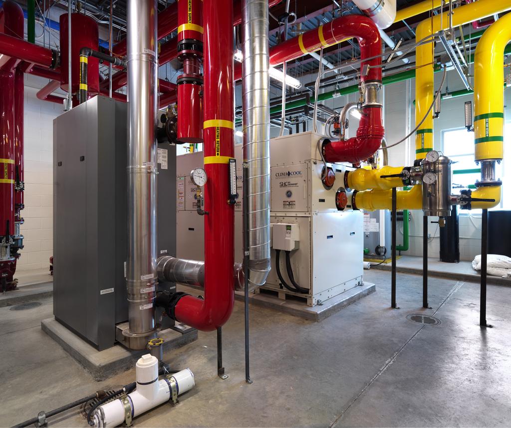
2 Table of Contents Introduction References/Nomenclature Conventions... 2 Terms & Definitions Module Size Selection...3 Water Source, Cooling Only and Heat Recovery (4-pipe)...4 Air Cooled, Cooling Only (2-pipe) Water Source, Heat Pump (4-pipe)...5 Air Source, Heat Pump (2-pipe)...5 Water Source, SHC Heat Pump (6-pipe) Integral 6 Header SHC Bank Layout...8 Air Source, SHC Heat Pump (4 pipe)...8 Water Source, SHC Cooling Dual Source (6-pipe)...9 Water Source, SHC Heating Dual Source (6-pipe) Water Source, SHC Heat Recovery (6-pipe) Operational Envelope Motorized alves System Bypass Design Frequently Asked Questions ClimaCool Modular Chiller System with five 85-ton modules 2019 ClimaCool Corp. All rights reserved.


3 Introduction The use of modular chiller products has distinct advantages over a typical chiller/boiler system in that having multiple independent modules and refrigeration circuits will lessen the amount of down time during routine servicing and repairs. The modular chiller system can be designed with many incremental steps of capacity as well as potential for system expansion to match nearly any project requirement. It is important for the designer to understand not only the maximum capacity requirement of the load, but also the minimum steps of capacity during light loads to properly select the right size and number of modules in the chiller plant. As an introduction to modular chillers, all ClimaCool chillers, with the exception of the Model UGW Water Cooled Compact Screw unit, will have two independent R-410A refrigeration circuits in each individual module. Both of these refrigeration circuits will be served by common water flow. In a typical water cooled application with nominal water flows of 2.4 gpm/ ton through the evaporator BPHE (brazed plate heat exchanger) and 3.0 gpm/ton through the condenser BPHE, the delta temperature entering and leaving both BPHE s will be 10 F with both compressors running, and 5 F with one compressor running. The operation limitations found in the respective product s Installation, Operation & Maintenance manual (IO&M) will list the minimum and maximum delta temperatures along with the minimum and maximum flow rates, of which, will correspond to approximately a minimum ΔT of 5 F and a maximum ΔT of 20 F for the evaporator, and a minimum ΔT of 5 F and a maximum ΔT of 30 F for the condenser. In addition to water flow rate in gallon per minute as detailed above, there is also a minimum requirement of total number of system gallons in each water loop for adequate thermal mass to prevent short cycling. This requirement is six gallons of fluid per ton of refrigeration. For example, a bank of three 50-ton modules will require a minimum loop volume in each water loop of 3 x 50 x 6 = 900 gallons of total system fluid. This application guide was developed to help users better understand how to design modular chiller systems and to answer the many questions that may arise during the design and operation of a modular chiller plant. While every effort has been made to cover the many details, there are many options in designing and operating chiller plants, so do not hesitate to contact ClimaCool or your local representative to answer any additional questions that you may have. ClimaCool Modular Chiller System installed with three simultaneous heating and cooling modules ClimaCool system with separated air cooled modules operating as one bank. 1
4 References/Nomenclature Conventions in This Manual This manual describes the operation and provides illustrations of various system applications of ClimaCool modular chillers, both water cooled and air cooled. Model nomenclature used in this manual refers to ClimaCool Modular Chiller models. For simplicity and clarity, single line (intending to indicate both supply and return) water piping drawings are used to illustrate cooling (chilled water), heating (hot water) and source (source water); separate supply and return piping is not shown. Terms and Definitions Chiller Bank - The entire chiller including all individual chiller modules Chiller Module - An individual chiller within the Bank DP - Delta Pressure or pressure difference DPT - water Differential Pressure Transducer that monitors the water flow through each of the chiller headers. Its sole purpose it to provide a loss of flow shutdown of the chiller when the differential pressure across its headers falls below the trip point. DT - Delta Temperature or temperature difference Headers or Pipe - The 6-inch or 8-inch steel headers that run through the chiller bank from one end to the other and are field connected between modules with grooved couplings. Load HX - This terminology is used for Heat Pump modules instead of using of the term for non-heat pump modules. In a heat pump module, the evaporating and condensing of refrigerant inside a heat exchanger changes with the usage of the heat exchanger depending on the operating mode of the module. This is the Heat Exchanger within a chiller module that provides the building loads with chilled water or hot water for the purpose of conditioning the building zones. Loads - The devices being served with chilled or hot water system for heating or cooling the building zones. Master Controller - The ClimaCool CoolLogic Chiller System Controller which controls the staging of the chiller modules compressors and provides all operational data from the modules to a central location. Refrigeration Circuit - Each individual chiller module contains two independent refrigeration circuits. These two refrigeration circuits share the same water circuits within a module. Source HX - The terminology used for Heat Pump modules instead of the use of the term Condenser for non-heat pump modules. In a heat pump module, the evaporating and condensing of refrigerant inside a heat exchanger changes with the usage of the heat exchanger depending on the mode the module is operating in. This is the heat exchanger within a chiller module that is used to reject heat to (Cooling mode), or absorb heat from (Heating mode) an external device such as a cooling tower, geothermal well field, dry cooler, etc. System - The entire chilled or condenser water system outside of the chiller itself. This includes all external piping, pumps, tanks, building loads such as air handlers, fan coils, chilled beams, etc. 2

5 Module Size Selection When selecting modular chiller sizes to meet the project full load tonnage, incremental capacity steps provided should be considered to provide a good balance between the building load profile and the available capacity steps of the chiller. If the total chiller size for the load is equal to 210 tons, the chiller sizes can be selected as one of the following examples, since both choices provide the total tonnage required. Example 1: three 70-ton chillers for a total of 210 tons Example 2: seven 30-ton chillers can be selected If space is an issue where seven 30-ton modules take up too much space, another consideration would be to utilize the three 70-ton modules and outfit a lead module with variable frequency drives (FD) on the two compressors. This module can be set up as a Trim Chiller, that will be first on, last off and can fill in between standard On/Off module capacity steps. Larger tonnage modules (50, 70 and 85-tons) are best applied with FDs when smaller capacity steps are required. Depending on the compressor model used, the available turndown is 35 Hz (58%) for larger compressors and 45 Hz (75%) for smaller compressors. Smaller tonnage modules (15, 25 and 30-tons) that require additional capacity turndown can be applied with digital scroll compressors. The digital scroll compressor can provide a turn-down to about 30% capacity. Again, a lead module can be selected to apply the two digital compressors on as a Trim Chiller that will be first on last off and can fill in between standard ON/OFF module capacity steps. For the purpose of attaining incremental capacity steps between compressors using FD or digital compressors, it is not necessary to outfit all modules with FD-driven compressors unless equalized runtime is a concern. Contact ClimaCool Engineering for recommendations on the best application of variable capacity compressor for a specific project. 3


6 Water Source, Cooling Only and Heat Recovery (4-pipe) UCW cooling only, 4-pipe module, heat is rejected to a geothermal well field or cooling tower (see Figure 1). The UCH heat recovery, 4-pipe module, Figure 1, where there are three modes of operation: cooling, heating and heat recovery. The modes available are NOT independent by module. The entire bank will operate in one of the three modes. In cooling mode, the cooling supply water setpoint is used to determine the stages of compressors required. In heating mode, the heating supply water setpoint is used to determine the stages of compressors required. In heat recovery mode, the cooling water and heating supply water setpoints are both used to determine the stages of compressors required. For this mode, the first setpoint met will stage the system down or off as needed sacrificing the opposite modes setpoint. Figure 1 UCW/H, Cooling Only and Heat Recovery Module 1 Cooling Module 2 Standby Module 3 Cooling Source or Heating Figure shows a bank of three modules: Module 1 in Cooling Module 2 in Standby Module 3 in Cooling Condenser Condenser Condenser Load Cooling *Simplified single line water circuit shown; =motorized isolation and control valve Air Cooled, Cooling Only (2-pipe) The UCR and UCA cooling only modules where the heat will be rejected to either a remote air cooled condenser, Model UCR, 2-pipe module, or an integral air cooled condenser, model UCA 2-pipe module (see Figure 2). Figure 2 UCR/UCA, Cooling Only Module 1 Cooling Module 2 Standby Module 3 Cooling Airflow Airflow Figure shows a bank of three modules: Module 1 in Cooling Module 2 in Standby Module 3 in Cooling Load Cooling *Simplified single line water circuit shown; =motorized isolation and control valve 4


. With Model UCA units, the ambient air serves as the source.")
7 Water Source, Heat Pump (4-pipe) The UCH heat pump, 4-pipe module has two modes of operation, either cooling or heating (see Figure 3). The modes available are NOT independent by module. All modules in a bank will operate in the same mode. The refrigerant reversing valve is used to index the module into cooling mode or heating mode. The load heat exchanger will provide chilled water to the load loop in cooling mode or hot water to the load loop in heating mode. The source heat exchanger will reject heat to the source in the cooling mode and absorb heat from the source in the heating mode. Figure 3 UCH, Heat Pump Source or Cooling Module 1 Heating Module 2 Standby Module 3 Heating Figure shows a bank of three modules: Module 1 in Heating Module 2 in Standby Module 3 in Heating Reverse Cycle Source HX Load HX Source HX Load HX Reverse Cycle Source HX Load HX Load Heating *Simplified single line water circuit shown; =motorized isolation and control valve Air Source, Heat Pump (2-pipe) UCA integral air source condenser reversible heat pump, operates as described above, with the load heat exchanger producing chilled water in the cooling mode and hot water in the heating mode (see Figure 4). With Model UCA units, the ambient air serves as the source. Figure 4 UCA, Heat Pump Module 1 Heating Module 2 Standby Module 3 Heating Airflow Airflow Figure shows a bank of three modules: Module 1 in Heating Module 2 in Standby Module 3 in Heating Reverse Cycle Load HX Load HX Reverse Cycle Load HX Load Heating * Simplified single line water circuit shown; =motorized isolation and control valve *Simplified single line water circuit shown; =motorized isolation and control valve 5


8 Water Source, SHC Heat Pump (6-pipe) The UCH simultaneous heating and cooling heat pump (SHC), 6-pipe module, has internal valves per Figure 5. Each module has two modes of operation, heating or cooling. This is accomplished by use of reversing valves to reverse the flow within the module refrigeration circuits. Both refrigerant circuits within each module must operate in the same mode, heating or cooling, since the heat exchangers both share a common water circuit. Any module may operate in either mode, heating or cooling, regardless of the position in the bank; provided header bypass kits are installed at the 3 chiller headers. In the cooling mode, the chilled water is routed to the chilled water header cooling loop and the condenser water is routed to the source water header loop. In the heating mode, the chilled water is rejected to the source water header loops and the condenser water is rejected to the hot water header loops. An added benefit is the heat that is rejected to the source water loop from modules operating in cooling mode can be reclaimed by modules operating in heating mode taking advantage of the refrigeration process. Figure 5 UCH SHC, Heat Pump Module 1 Cooling Module 2 Standby Module 3 Heating Source Figure shows a bank of three modules: Module 1 in Cooling Module 2 in Standby Module 3 in Heating Source HX Rev. alve Load HX Source HX Rev. alve Load HX Source HX Rev. alve Load HX Load Cooling Load Heating *Simplified single line water circuit shown; =motorized isolation and control valve The Simultaneous Heating and Cooling Heat Pump chiller, ClimaCool UCH Unit SB0S model, is a six-header and five-valve unit that has two modes of operation: Cooling Only and Heating Only. The Cool Loop connects to the Load HX with one proportional valve and one ON/OFF valve. The Heat Loop connects to the Load HX with one proportional valve and one ON/OFF valve. The Source Loop connects to the Source HX with one proportional valve and one manual ball valve. The Source Loop proportional valve will modulate for refrigerant discharge pressure control in the Cooling mode and for suction pressure load limiting in Heating mode. Any module in a chiller bank will be automatically indexed into either of the available modes on a first come-first served basis based on the Heat and Cool PID count which is derived from the building cooling and heating demand. Any module can also be manually fixed into either mode. Figures 6 and 7 identify the modes of operation as they pertain to the water loop that the Load Heat Exchanger serves. The Load Heat Exchanger of each individual module in the bank can serve only one of the two load loops at a time. Having multiple modules in a chiller bank allows the two simultaneous modes of operation, Heat mode and Cool mode. Since the Load Heat Exchanger can serve two water loops (Cooling and Heating); there will be mixing of water from one loop to the next loop over time. It is important in designing the piping system to confirm that the two loops will have the same fluid type, i.e. glycol type and percentage, and very similar fluid pressure at the chiller location within the piping system. This mixing of loops does not take place while a module is in operation. The chiller module will first shut down the compressors, close the currently used valve pair, then open the new valve pair. The fluid (and pressure) inside the HX that is 6

9 Water Source, SHC Heat Pump (6-pipe) Cont d. trapped by the closed valve pair will be transferred to the new water loop the HX will be serving. It is also important to note when selecting the fluid pump location as being defined as a Push Through or Draw Through application at the chiller in an effort to keep all the loops at similar pressures at the chiller location. ClimaCool recommends Push Through for the loop pumps. Failure to design the system in this manner will result in over-pressurization of the lowest pressure loop and a loss of pressure in the highest pressure loop. Figure 6 Cooling Mode, SHC Simultaneous Heating and Cooling Heat Pump Figure 7 Heating Mode, SHC Simultaneous Heating and Cooling Heat Pump 7

 Model UCA simultaneous heating and cooling, air cooled packaged heat pump modules utilizing")
10 Integral 6 Header Simultaneous Heating and Cooling Bank Layout Both the Cool and Heat loops must have the same relative loop pressure as during mode changes, a varied higher loop pressure trapped in the heat exchangers can be transferred to a loop with a lower pressure. Both pumps must be arranged as Push Through or Draw Through. Do not mix the pump application arrangement. Push Through arrangement is optimum and recommended. Figure 8 Cooling Mode, SHC Simultaneous Heating and Cooling Heat Pump Air Source, SHC Heat Pump (4-pipe) Model UCA simultaneous heating and cooling, air cooled packaged heat pump modules utilizing 4-pipes, two for hot water and two for chilled water, are illustrated in Figure 9. Any module regardless of the position in the bank can operate in either mode, heating or cooling. Figure 9 UCA SHC, Heat Pump, 4 pipe Module 1 Cooling Module 2 Standby Module 3 Heating Airflow Airflow Figure shows a bank of three modules: Module 1 in Cooling Module 2 in Standby Module 3 in Heating Load HX Load HX Reverse Cycle Load HX Load Cooling Load Heating *Simplified single line water circuit shown; =motorized isolation and control valve 8
11 Water Source, SHC Cooling Dual Source (6-pipe) The UCH simultaneous heating and cooling, cooling dual source, 6-pipe (see Figure 10) is shown as a bank of modules with two modes of operation, cooling only and heat recovery. These modes are accomplished by the use of motorized valves between the heat exchangers and the appropriate headers. In the cooling only operation, the water that circulates through the condenser heat exchanger is routed to the pair of headers labeled Source. This source loop water is sent to a geothermal well field or cooling tower for the heat to be rejected and not utilized in any process. The chilled water from the evaporator heat exchanger will always be directed to the cold header loop to be used for the chilled water loop of the building. In the heat recovery operation, the water that circulates through the condenser heat exchanger is routed to the pair of headers labeled Heat. This water is sent to the heating water loop of the building to be utilized for heating purposes instead of simply rejected and unused. Additionally, in the heat recovery mode the chilled water from the evaporator heat exchanger will be directed to the cold header loop to be used for chilled water supply to the building. In heat recovery mode, the first setpoint met, heat or cool, will satisfy and stage down the module in that mode. Figure 10 UCH SHC, Cooling Dual Source Module 1 Heating and Cooling Module 2 Standby Module 3 Cooling Source Figure shows a bank of three modules: Module 1 in Heating and Cooling Module 2 in Standby Module 3 in Cooling Condenser Condenser Condenser Load Cooling Load Heating *Simplified single line water circuit shown; =motorized isolation and control valve Water Source, SHC Heating Dual Source (6-pipe) The UCH simultaneous heating and cooling, heating dual source, 6-pipe (see Figure 11) with a bank of modules has two modes of operation available, heating only and heat recovery. These modes are accomplished by the use of motorized valves between the heat exchangers and the appropriate headers. In the heating only operation, the water that circulates through the condenser heat exchanger is always routed to the heating water loop. At the same time, the chilled water from the evaporator heat exchanger is routed to the source loop and is used for no purpose other than to absorb heat for the refrigeration process. In the heat recovery operation, the water that circulates through the condenser heat exchanger is routed to the pair of headers labeled Heat. This water is sent to the heating water loop of the building to be utilized for heating purposes instead of simply rejected and unused. Additionally, in the heat recovery mode, the chilled water from the evaporator heat exchanger will be directed to the cold header loop to be used for chilled water supply to the building. In heat recovery mode, the first setpoint met, heat or cool, will satisfy and stage down the module in that mode. 9

 The UCH simultaneous heating and cooling, heat recovery, 6-pipe (see Figure 12) show as a bank of modules with three modes of operation available, heating only, cooling only and heat")
12 Water Source, SHC Heating Dual Source (6-pipe) Cont d. Figure 11 UCH SHC, Heating Dual Source Module 1 Heating and Cooling Module 2 Standby Module 3 Heating Source Figure shows a bank of three modules: Module 1 in Heating and Cooling Module 2 in Standby Module 3 in Heating Condenser Condenser Condenser Load Cooling Load Heating *Simplified single line water circuit shown; =motorized isolation and control valve Water Source, SHC Heat Recovery (6-pipe) The UCH simultaneous heating and cooling, heat recovery, 6-pipe (see Figure 12) show as a bank of modules with three modes of operation available, heating only, cooling only and heat recovery. These modes are accomplished by the use of motorized valves between the heat exchangers and the appropriate headers. In the heating only operation, the water that circulates through the condenser heat exchanger is routed to the heating water loop. At the same time, the chilled water from the evaporator heat exchanger is routed to the source loop and is used for no purpose other than to absorb heat for the refrigeration process. In the cooling only operation, the water that circulates through the condenser heat exchanger is routed to the pair of headers labeled Source. This source loop water is sent to a geothermal well field or a cooling tower for the heat to be rejected and not utilized in any process. The chilled water from the evaporator heat exchanger will be directed to the cold header loop to be used for chilled water loop to the building. In the heat recovery operation, the water that circulates through the condenser heat exchanger is routed to the pair of headers labeled Heat. This water is sent to the heating water loop of the building to be utilized for heating purposes instead of simply rejected and unused. Additionally, in the heat recovery mode, the chilled water from the evaporator heat exchanger will be directed to the cold header loop to be used for chilled water supply to the building. In heat recovery mode, the first setpoint met, heat or cool, will satisfy and stage down the module in that mode. Figure 12 UCH SHC, Heat Recovery Module 1 Heating Module 2 Heating and Cooling Module 3 Cooling Source Figure shows a bank of three modules: Module 1 in Heating Module 2 in Heating and Cooling Module 3 in Cooling Condenser Condenser Condenser Load Cooling Load Heating *Simplified single line water circuit shown; =motorized isolation and control valve 10

13 Water Source, SHC Heat Recovery (6-pipe) Cont d. Three versions of the ClimaCool Simultaneous Heating and Cooling Heat Recovery chiller are available. The UCH WB0S model is a 6 header 8 valve unit that has three modes of operation: Heat Recovery, Cooling Only, and Heating Only The UCH TB0S model is a 6 header 6 valve unit that has only two modes of operation: Heat Recovery and Cooling Only The UCH B0S model is a 6 header 6 valve unit that has only two modes of operation: Heat Recovery and Heating Only Any module in a chiller bank can be automatically or manually indexed into any of the available modes based on the model number. Figures 13, 14 and 15 identify the modes of operation as it pertains to the water loop that each heat exchanger (HX) serves. Each heat exchanger can serve up to two separate loops to provide the various modes of operation. Since there are two heat exchangers and three water loops and each heat exchanger can serve up to two water loops; there will be mixing of water from one loop to the next loop over time. This is important to note in designing the piping system to confirm that all three loops will have the same fluid type, i.e. glycol type and percentage; and very similar fluid pressure at the chiller location within the piping system. This mixing of loops does not take place while a module is in operation. The chiller module will first shut down the compressors, close the currently used valve pair, then open the new valve pair. The fluid (and pressure) inside the heat exchanger that is trapped by the closed valve pair will be transferred to the new water loop the heat exchanger will be serving. This is also important to note when selecting the fluid pump location as being a Push Through or Draw Through application at the chiller in an effort to keep all the loops at similar pressures at the chiller location. ClimaCool recommends Push Through for all three loop pumps. Failure to design the system in this manner will result of over pressurization of the lowest pressure loop and a loss of pressure in the highest pressure loop. Figure 13 Heat Recovery Mode, SHC Heat Recovery 6-Header Chiller Module 11


14 Water Source, SHC Heat Recovery (6-pipe) Cont d. Figure 14 Cooling Mode, SHC Heat Recovery 6-Header Chiller Module Figure 15 Heating Mode, SHC Heat Recovery 6-Header Chiller Module Figure 16 Recommended Layout for SHC Integral 6-Header Dual Mode Simultaneous Heating and Cooling Heat Recovery Bank 12
15 Operational Envelope A maximum Delta T of 100 F is allowed between leaving load temperature and leaving source temperature for all products, except the UCA Air C0oled Heat Pump, where the limit is 90 F, as well as leaving load heating temperature and leaving load cooling temperature for simultaneous heating and cooling heat recovery products. Example: if using glycol and a chilled water temperature of 25 F, the maximum source water temperature would be 125 F. If the source loop has the potential to drop below this 100 F differential temperature limit, the recommendation is to either lower the hot water setpoint accordingly or provide a supplemental heat source to the source loop. Motorized alves ClimaCool modular chiller banks can be provided with or without motorized valves at each module. When provided without motorized valves, it is essential to use equal circuit loading in which one compressor in each module will incrementally start and run before the second compressor in each module is called to run. Table 1, Staging Order, Bank without motorized valves M indicates Module number; C indicates Compressor/circuit number Staging Order M1C1 M2C1 M3C1 M4C1 This allows all the heat exchangers to become active, minimizing the amount of unconditioned bypass water that will affect the resulting supply chilled water temperature. When modules are provided with motorized valves, staged circuit loading is utilized, in which each module starts both compressor one (1) and two (2) before the next module is indexed to run. Table 2, Staging Order, Bank with motorized valves M indicates Module number; C indicates Compressor/circuit number Staging Order M1C1 M1c2 M2C1 M2C2 M3C1 M3C2 As each module is indexed to operate, the motorized valves will open. Once the mechanical end switches of both the load and source valves electrically close, the compressor will be allowed to operate. ClimaCool utilizes two types of motorized valves. The first type is an ON/OFF valve and the second is a proportional valve. On a standard UCW, 4-pipe, cooling only module with motorized valves, the evaporator (load) motorized valve will open to 100%. The end switch is field adjusted to electrically close at approximately 25% to 30% of the valve opening position allowing the compressor to start. The condenser (source) motorized valve is a proportional type having a signal input range of 2.0 to 10 vdc, 2.0 vdc being closed and 10 vdc being 100% open. ClimaCool uses a default minimum position of 3.6 vdc, adjustable, for the condenser (source) proportional motorized valve. This is for the purpose of refrigerant head pressure control when the entering condenser water temperature is low. When the module is indexed to operate and the valves are commanded to open, the evaporator motorized valve will open to 100%, as described above, and the condenser motorized valve will open to its minimum position. All proportional valves that are used with a minimum position must have the actuator end switch adjusted so contact closure is ensured at the minimum voltage position or the compressor will not start. It is possible to increase the minimum position voltage, however, it will be at the expense of modulation range for refrigerant head pressure control. The typical refrigerant head pressure target is 280 psig. Above this pressure the motorized valve will be at 100% open; below this pressure the valve will modulate to maintain the target pressure. All simultaneous heating and cooling (SHC) designed modules also incorporate proportional motorized valves for the purpose of load limiting. Under certain mode changeover conditions the active evaporator heat exchanger may experience a heavily loaded water loop in which high refrigerant suction pressures will result. The high suction pressure setpoint is set for 140 psig. When the suction pressure exceeds this value, one motorized valve for the SHC heat pump or both motorized valves for the SHC heat recovery will modulate from fully open toward the minimum position to maintain the suction pressure at or near setpoint. This helps to prevent operation of the compressor outside its design envelope. 13
16 System Bypass Design ariable Flow Chilled Water, Hot Water and Simultaneous Heating & Cooling Systems System Side Bypass alves A System Side (load side) Bypass alve is required for the chilled, heat, and source loops with variable pumping and all load side 2-way valves. These bypasses are best sized to accommodate the minimum chiller flow at maximum chiller load of the entire chiller bank. There can be short durations when the building load diminishes quickly, closing 2-way valves, causing the variable speed pump to ramp down before the chiller senses the load change and has an opportunity to stage down. Without a system side bypass to monitor the chiller header DP and modulate open as the chiller header DP begins to fall below the submitted value, nuisance loss of flow and low temperature/pressure alarms can occur. Figure 17 Typical Load Bypass alve Arrangement TYPICAL LOAD BYPASS ALE ARRANGEMENT LOAD 1 LOAD 2 LOAD 3 LOAD X FROM CHILLER BANK TO CHILLER BANK TYPICAL CHILLED AND HOT WATER LOAD SIDE BYPASS ALES SIZE EQUIALENT TO ONE MODULE WORTH OF FLOW Chiller Header Bypass alves The Chiller Header Bypass valves are 2-position valves and are only open when none of the modules have internal valves open to that respective loop. Their only two purposes are to prevent pump deadheading when none of the module valves are open and to provide 1 modules worth of flow across the controlling leaving water temperature sensor in the thermowell so the CoolLogic chiller system controller can see the building load. Figure 18 Chiller Header Bypass *Header bypass valve may be installed at either end of the bank. The operation of each header bypass pertains only to the loop on which it is installed. Taken on a loop by loop basis, the Master Controller monitors all the motorized valve end switches within each of the modules that connect to that loop for that mode of operation. Example: The Load Cooling Loop has motorized valves connected to the load heat exchangers. When no module has motorized valves open to the Load Cooling Loop, all those motorized end switches will be electrically open, showing a closed status in the BACview interface. The Master Controller recognizes this and signals the header bypass valve to open, allowing flow through the header bypass. Once the first module is indexed to cooling mode and both motorized valves mechanically open (end switches electrically close ); the header bypass valve is signaled to mechanically close; as the module is now indexed to Cool mode is providing the water flow path, therefore the header bypass valve is no longer needed. 14

17 Modules can also be assigned for fixed bypass for heating, cooling and source flow, however, this limits the number of modules remaining for that duty. For example, with an SHC OnDemand heat pump system with four modules, if one module is designated for heating bypass and one module for cooling bypass, the system now only allows a maximum of three modules for heating or three modules for cooling. Anytime the system bank of modules is enabled, and no internal module valves have opened yet, the external bypass, or internal fixed module, valves will be open, allowing the minimum flow to prevent pump dead-heading and allow accurate sensing of the loop water. Once the first module is indexed to operate and the internal motorized valve begins to open, the electrical closure of the auxiliary end switch will trigger the CoolLogic Controller to close the external bypass valve, or internal fixed module valve(s), as they are no longer needed for the purpose above. In the simultaneous heat pump and heat recovery models, the fixed module can be used, but now there is more than one mode of operation. This requires one module to be fixed in cool and a second module to be fixed in heat. The cooling mode of operation only uses the cool loop and the source loop and the heat mode only uses the heat loop and the source loop. Fixing only one module in a mode will only allow the minimum internal flow bypass in only two of the three loops. This is why two modules need to be fixed in opposite modes. If four modules are installed in a bank and module one is fixed in cool and module two is fixed in heat, modules three and four will be deemed open (or standby), available for either mode as the cooling or heating demand dictates. Using this method, there can only be three modules available for cool or three modules available for heat. It is strongly recommended to utilize the external bypasses over the fixed module method so that all modules in a bank always will be available for any mode of operation. ClimaCool four-module bank with a CoolLogic chiller sytem controller 15
 When using motorized valves on the chiller modules, the chiller bank requires a variable flow arrangement as the flow requirement changes based on the")

18 System Bypass Design Cont d. ariable Primary Pump Systems (Pump Control) When using motorized valves on the chiller modules, the chiller bank requires a variable flow arrangement as the flow requirement changes based on the number of modules in operation. This can be accomplished by utilizing variable frequency drives to control pump speed and maintain the target delta pressure at the headers connected to the chiller bank. This target delta P will be the same regardless of the number of modules in operation. If the pump speed is controlled to a delta P at the load side of the system, as the load side valves begin to satisfy and modulate closed, the pumps respond by delivering a lesser flow to the chiller bank. When the chiller bank senses this drop in flow, the modules may have not yet staged down and could still be open in a temperature pull down situation. Loss of flow alarms, low or high water temp alarms and even low or high refrigerant pressure alarms can result. It is important to install 3-way valves or bypass valves at the load side of the system to keep flow above the minimum rate when these loads satisfy. Use of bypass valves at the far end of the system will also promote keeping the overall active loop volume high. The load side bypass valves are generally open when the load control valve is closed and could also operate in reverse proportion to the control valve. This is critical for maintaining proper flow at the load side of the system (Figure 17 is repeated below for convenience). When the system pump is controlled by the load side flow requirement, this system bypass valve can be controlled to maintain the proper differential pressure across the chiller bank. This will help ensure adequate flow at the chiller headers even as the loads stage down (internal chiller control valves close). Figure 17 Typical Load Bypass alve Arrangement Typical chilled and hot water load side bypass valve size equivalent to one module worth of flow As the building system DP falls, the pump speed increases supplying more fluid flow to the building. As the building system DP rises, the pump speed decreases providing less fluid flow to the building. Meanwhile, the building system bypass valve toward the end of the loop monitors field supplied and installed DP sensors at the chiller. As the chiller DP falls (due to load side valves closing and the pump speed decreasing), this bypass valve will proportionally open maintaining the DP at the chiller. The act of the bypass valve opening proportionally, allows the pump speed to increase supporting the flow needs of the chiller (see Figure 19). Figure 19 Pump Control from Load Side (representative of one loop) The pump speed will increase or decrease to maintain the submitted DP value across the chiller header. As chiller module internal valves open, the chiller header DP will fall. This will cause the pump speed to increase to maintain DP at the chiller header each time a new module opens its internal valves. Conversely, as the chiller modules satisfy and their internal valves close; the DP sensor will sense this increase in DP and the pump speed will decrease. Meanwhile, the building system DP set point will be maintained by the system bypass valve, proportionally opening when the system DP is high (when some load valves are closed) and proportionally closing when the System DP is low (as the load side valves are opening). When the load side valves are open (system bypass should be closed), this introduces additional load to the chiller, causing it to stage up to meet this increased load demand (see Figure 20). 16
19 Figure 20 Pump Control from Chiller Header (representative of one loop) Whichever method used, the system water flows must be controlled to keep a constant chiller header differential pressure and the DP to each active loop above the minimum flow trip point at all times or the above nuisance alarms will occur. The response time of the method used is also critical to prevent nuisance alarms. Freeze Protection Master Level The CoolLogic Master Controller has temperature sensor inputs in each entering and leaving loop connected to the bank of modules. They are also used for high or low entering and leaving temperature safeties. The CoolLogic Controller also has differential pressure transducer (DPT) inputs for each water loop. The sole purpose of the DPT is for low water flow protection for each loop, and can also be used by the technician or operator to monitor the chiller header differential pressures viewable at the BACview interface. Freeze Protection Module Level Each chiller module has independent freeze protection in the form of a leaving water temperature sensor at the heat exchanger, refrigerant low-side pressure transducer and refrigerant suction temperature. Each of these trips points are defaulted at values for use with straight water. The default leaving water temperature trip point at the module heat exchanger is 36 F. The module low refrigerant pressure trip point is 92 psig and the refrigerant low temperature trip is 32 F. Glycol Usage If glycol is used in a specific loop and these settings require adjustment, care must be taken to first confirm the type and percentage of glycol used in the loop. The ClimaCool Installation, Operation & Maintenance Manual (IO&M), containing the freeze chart for propylene and ethylene glycol, can be reviewed to determine the actual freeze point with the confirmed concentration. The IO&M manuals are available on the Literature page of ClimaCool recommends the module freeze temperature setting be adjusted no less than 8 F above the actual freeze point of the solution. The coincidental refrigerant low pressure and temperature trip points will also require adjustment in accordance with this value using a 5 F to 6 F approach temperature. For example, 30% propylene glycol has been confirmed to be present in a chilled water loop. The freeze point of this solution is 9 F. So the module leaving water freeze point should be set to 17 F, (9 F + 8 F = 17 F). Using the approach of 5 F the refrigerant temperature at this leaving water temperature is 12 F. Using a pressure temperature chart, the coincidental refrigerant pressure is approximately 65 psig. The low suction temperature trip point should also be adjusted to the minimum superheat above the adjusted saturated suction temperature. In the example above, the saturated temperature was 12 F + 6 F minimum superheat is an 18 F low suction temperature trip point. These numerous safeties provide added layers of protection from freeze failures. Even with layers of protective alarms, repeated resetting of alarms without correcting the root cause can eventually result in equipment failure. 17
20 System Bypass Design Cont d. Module and Compressor Rotation ClimaCool employs two methods of rotation operation: rotation of lead module and rotation of the lead compressor within a module. Rotation of the lead module method is done on a weekly basis. Each module s lead compressor run hours is polled on a weekly basis to determine which compressor has the lowest run hours. That module is selected to operate first in line followed by the next module with the second lowest lead compressors run hours. The lead lag rotation of the lead compressor within a module is done on a monthly basis. At the end of a run cycle at this interval the next run cycle will start the opposite compressor first and will repeat for each additional module in the bank. As the module stages up, it will follow the method of starting the lead compressor in a module with the lowest run hours. As the module stages down, it will stage off the lead compressor with the highest run hours first, the second highest run hours next, and so on. The purpose is for compressor runtime equalization. Remote Setpoint Adjust The chiller bank systems can be configured to accept a hardwired 2-10 vdc or 4-20 ma signal that can proportionally change the water temperature setpoints based on any criteria determined by others providing the signal. When there are also associated building automation system (BAS) points, the voltage or current valves can be written to those points to accomplish the same result. The remote temperature reset menu must be configured using the CoolLogic BACview device before it will be available. Configure the option from NONE to REMOTE (COOL OR HEAT) TARGET, set the minimum and maximum temperature range and configure the signal type to be used. Demand Limit The chiller banks can be configured to accept a hardwired 2-10 vdc or 4-20 ma signal that can proportionally change the number of compressors available to operate to reduce energy consumption. There are also associated BAS points these voltage or current values can be written to for accomplishing the same result. The Demand Limit menu must be configured using the CoolLogic BACview device before it will be available. Configure the option from NONE to DEMAND LIMIT MAX # OF COMPRESSORS. Also, toggle MANUAL SELECT (COOL OR HEAT) MODE DEMAND LIMITING to ON and the OLTS IN signal can be proportionally changed to set the number of available compressors. DC of 2=NO Demand Limit; 10=Full Demand Limit. % Heat /Cool Modules Limiting Control Scheme, Simultaneous Heating and Cooling Only This configuration provides a method of limiting the number of modules that are available for a given mode. The SELECT % HEAT COOL MODS menu must be configured using the CoolLogic BACview device before it will be available. Once configured ON, a fraction of heat mods and fraction of cool mods can be configured. FRACTION OF COOL MODS + FRACTION HEAT MODS must be less than or equal to 1.0. For example, if Heat is selected at 0.5 and Cool is selected at 0.5, then only one half of the modules in the bank are available for each mode. Trim Chiller Another advantage of the modular chiller is to mix and match the tonnage sizes and apply a concept called Trim Chilling or Trim Heating. A module of a smaller size than the others in a bank can be designated as a Trim Module so that it is always the first on, last off. During light loads, this is an advantage to use a smaller tonnage compressor circuit which will promote longer run times and minimize short cycling. This concept should also be applied for modules with digital or FD controlled compressors. 18
21 Frequently Asked Questions Can a chiller/heater header bypass be created with field supplied piping? Yes, the design piping must accommodate one module s worth of design flow, and be positioned so that the temperature and differential flow sensors sense active flow in the bypass mode. Additionally, control valve stroke time must be designed to match chiller internal valve time. Refer to the Chiller Header Bypass Drawing, Figure 17, repeated below for convenience. Figure 17 Typical Load Bypass alve Arrangement LOAD 1 LOAD 2 LOAD 3 LOAD X FROM CHILLER BANK TO CHILLER BANK Typical chilled and hot water load side bypass valve size equivalent to one module worth of flow Can the ClimaCool CoolLogic controls, via BACnet or other remote interface, be utilized to control a field supplied bypass? No, there are system communication delays, polling and network conflicts that strictly prohibit the use of ClimaCool sensors and controls for control of field supplied bypasses or other field installed items. The recommended method is to control via differential pressure across the chilled water/evaporator, hot water/condenser and source water systems. Note that the above strictly relates to the bypass at the chiller/heater system. In order to have a stable operating cooling and/or heating system, consideration must be given to the load side of the system as well, so that the building pumping system can maintain the chiller header differential pressures within a reasonable range of the submitted delta P at all times. Load Side System Bypass (Air Handler, Fan Coils, etc.) Is a bypass required at the load side of the system? Yes, a load system bypass or 3-way valves providing adequate minimum flow is required for preventing pump dead-heading, allowing active flow system sensing and preventing starving flow from the chiller/heater system. What are some examples of an acceptable load side system bypass? Utilize a quantity of 3-way control valves on the largest loads farthest from the chiller/heater system. Field piping with a control valve to provide a bypass across the larger system loads when the 2-way load side valves close. What amount of flow should the load side system bypass be sized for? If a single system side bypass valve is used, it should be sized to bypass the minimum water flow at maximum chiller load. There can be short durations when the building load diminishes quickly, closing 2-way control valves causing the pump to ramp down before the chiller has time to stage down. The bypass valve can monitor the chiller header DP and modulate open to maintain a minimum header DP. This will slightly ramp the pump and help to prevent nuisance loss of flow and low temperature alarms. Is there a required minimum system volume to maintain proper system thermal mass? Yes, a minimum of six gallons per nominal system ton are required to maintain proper system thermal inertia. This is to avoid short cycling of compressors in the chiller/heater system as well as prevent nuisance alarms. 19
22 Notes 20
23 Notes 21


24 Contact your local ClimaCool representative or visit our web site at to find out more about the heating and cooling solutions to fit your application needs. on DEMAND SIMULTANEOUS HEATING AND COOLING 15 S. irginia Oklahoma City, OK Phone: Fax: ClimaCool works continually to improve its products. As a result, the design and specifications of each product at the time for order may be changed without notice and may not be as described herein. Please contact ClimaCool s Customer Service Department at for specific information on the current design and specifications. Statements and other information contained herein are not express warranties and do not form the basis of any bargain between the parties, but are merely ClimaCool s opinion or commendation of its products. USGBC and related logo is a trademark owned by the U.S. Green Building Council and is used with permission. Doc# App. Guide January 2019
All Chiller Products. Water Cooled and Air Cooled Modular Chillers Available in 208, 230, 460 & 575 Volts Application Ranges from 30 to 1,000 Tons
 All Chiller Products Water Cooled and Air Cooled Modular Chillers Available in 208, 230, 460 & 575 Volts Application Ranges from 30 to 1,000 Tons ClimaCool modular chillers. No compromises. They re not
SHConDEMAND. True Redundancy. Heating. Cooling. Simultaneous. Efficient. Reliable
 True Redundancy Heating Efficient Cooling Reliable Simultaneous SHConDEMAND UCH Series Water Cooled 15, 25, 30, 50, 70 and 85 Tons Configurable up to 1,000 Tons Available in 208, 230, 460 and 575 olts
WaterFurnace FX10 Application Guide Reversible Chiller
 2011 WaterFurnace FX10 Application Guide Reversible Chiller Introduction This manual provides information about the FX10 Water Source Heat Pump (WSHP) controller as it relates to dual compressor water
Method to test HVAC equipment at part load conditions
 IPLV Method to test HVAC equipment at part load conditions For water cooled chillers: 100% load ( % hrs) + 75% ( Hrs ) + 50% ( Hrs ) + 25% ( Hrs ) = IPLV value Manufacturer can favor this number by tweaking
Variable refrigerant flow (VRF) systems
 systems") SBS5311 HVACR II http://ibse.hk/sbs5311/ Variable refrigerant flow (VRF) systems Ir. Dr. Sam C. M. Hui Faculty of Science and Technology E-mail: cmhui@vtc.edu.hk Oct 2017 Contents System Overview Components
SBS5311 HVACR II http://ibse.hk/sbs5311/ Variable refrigerant flow (VRF) systems Ir. Dr. Sam C. M. Hui Faculty of Science and Technology E-mail: cmhui@vtc.edu.hk Oct 2017 Contents System Overview Components
AHWG Remote Mount Hot Water Generator Module for TTP Series Outdoor Split Unit
 A Remote Mount Hot Water Generator Module for TTP Series Outdoor Split Unit Installation, Operation & Maintenance Instructions 97B0080N01 B Table of Contents Model Nomenclature Example 3 Description and
APPLICATION BROCHURE Chillers and Heat Pumps Hydraulics Manual. Suggestions for the hydraulic integration of chillers and heat pumps
 APPLICATION BROCHURE Chillers and Heat Pumps Hydraulics Manual Suggestions for the hydraulic integration of chillers and heat pumps Table of Contents From practical experience, for your practical needs...
AHWG Remote Mount Hot Water Generator Module
 A Remote Mount Hot Water Generator Module For GT-PE (50YPS) Series Outdoor Split Unit Installation, Operation & Maintenance Instructions 97B0080N02 B Model Nomenclature Example 3 Description and Installation
Digital Precise Air Control - DPAC
 Digital Precise Air Control - DPAC Mode Enable Sensor Options The temperature of this sensor will determine if the unit is in heating, cooling or vent mode during Occupied operation. The following options
THE ULTIMATE ROOFTOP SOLUTION
 Configured Packaged Rooftop Solutions Specializing in Dedicated Outdoor Air Systems (DOAS) Capacities from 6 to 90 Tons Available in 208, 230, 460 and 575 Volts THE ULTIMATE ROOFTOP SOLUTION Service Friendly
PACKAGED AIR COOLED Product Data Catalog
 PACKAGED AIR COOLED Product Data Catalog MODELS ASP-10A ASP-15A ASP-20A ASP-00P ASP-00F ASP-00G A MEMBER OF MARDUK HOLDING COMPANY, LLC The Leader in Modular Chillers ETL and CSA Approved CHILLER MODULES
The Book of AERMEC NRL Sequence of Operation
 The Book of AERMEC NRL Sequence of Operation Heating and cooling operation. 2 Sequence of operation Aermec air to water chiller/heat pump use Hydronic s in conjunction with refrigerant to provide heating
SECTION SEQUENCE OF OPERATIONS FOR HVAC CONTROLS
 PART 1 - GENERAL SECTION 23 09 93 SEQUENCE OF OPERATIONS FOR HVAC CONTROLS 1.1 SUMMARY A. This Section includes control sequences for HVAC systems, subsystems, and other equipment. B. See Division 23 Section
GeneSys Air-Cooled Screw Compressor Chiller
 Operation Manual OM AGSB-5 Group: Chiller Part Number: 331373201 Date: June 2005 Supersedes: OM AGSB-4 GeneSys Air-Cooled Screw Compressor Chiller AGS 230A/B through AGS 475A/B, 60 Hertz AGS 206A/B through
Screw Water Cooled Chiller SCW210
 Screw Water Cooled Chiller SCW210 Nominal Cooling Capacity 185.1 to1480.8 kw Refrigerant: R407C and R134a Contents Features 1 MV7 Control 3 Physical Data 5 Unit Performance 8 Chiller Selection 9 Physical
BRINE CIRCULATED ICE THERMAL STORAGE SYSTEM DESIGN - CASE ILLUSTRATION - Partial Ice Storage for Air Conditioning Application
 1 BRINE CIRCULATED ICE THERMAL STORAGE SYSTEM DESIGN - CASE ILLUSTRATION - Partial Ice Storage for Air Conditioning Application By: T. S. Wan Date: Oct. 7, 1995 Copy Right 1995 by T. S. Wan All rights
SAMPLE. added benefit of reduced operating costs during low demand periods, such as spring and fall.
 Chapter 4 Variable-speed pumps. A variable-speed pump varies the flow rate by maintaining a constant pressure differential as zone valves open and close. A sensor measures the difference in pressure between
Chiller Plant Design. Julian R. de Bullet President debullet Consulting
 Chiller Plant Design Julian R. de Bullet President debullet Consulting 703-483-0179 julian@debullet.com This ASHRAE Distinguished Lecturer is brought to you by the Society Chapter Technology Transfer ASHRAE
TRACE 700. Slide 1. Hello, my name is Nick Cavitt and I m a marketing engineer in the C.D.S. group at TRANE.
 Slide 1 TRACE 700 Chiller Sequencing and Controls Hello, my name is Nick Cavitt and I m a marketing engineer in the C.D.S. group at TRANE. Today, we will be talking about the Plant Sequencing and Controls
SECTION SEQUENCE OF OPERATIONS FOR HVAC CONTROLS
 SECTION 23 09 93 SEQUENCE OF OPERATIONS FOR HVAC CONTROLS PART 1 - GENERAL 1.1 SUMMARY A. This Section includes control sequences for HVAC systems, subsystems, and equipment. B. See Division 23 Section
Verasys System Operation Overview Technical Bulletin
 Contents subject to change. Verasys System Operation Overview Technical Bulletin Code No. LIT-12012370 Issued January 2016 Refer to the QuickLIT Web site for the most up-to-date version of this document.
By Thomas H. Durkin, P.E., Member ASHRAE, and James B. (Burt) Rishel, P.E., Fellow/Life Member ASHRAE
 Rishel, P.E., Fellow/Life Member ASHRAE") By Thomas H. Durkin, P.E., Member ASHRAE, and James B. (Burt) Rishel, P.E., Fellow/Life Member ASHRAE T he advent of the small scroll or screw chiller, capable of producing condenser water as high as 140
By Thomas H. Durkin, P.E., Member ASHRAE, and James B. (Burt) Rishel, P.E., Fellow/Life Member ASHRAE T he advent of the small scroll or screw chiller, capable of producing condenser water as high as 140
Scroll Water Cooled Chiller
 Scroll Water Cooled Chiller SRW145 Nominal Cooling Capacity 77 to 1232 kw Refrigerant: R407C and R134a Contents Features 1 MV7 Control 3 Physical Data 5 Unit Performance 8 Chiller Selection 9 Physical
Commercial Buildings Chilled water systems efficiency By Jens Nørgaard, Senior Application Manager, Grundfos, Denmark
 Commercial Buildings Chilled water systems efficiency By Jens Nørgaard, Senior Application Manager, Grundfos, Denmark Introduction: Energy use is the single largest operating expense in commercial office
AC SYSTEM CONFIGURATION- CENTRAL CHILLER PLANT
 AC SYSTEM CONFIGURATION- CENTRAL CHILLER PLANT Central Chiller Plant (with Cooling Tower and Chilled Water distribution) The other AC configuration is called a Chilled Water or Larger Cooler system. It
1.0 Digital Controller
 Form CP-AHU D19_D21_D22 (11-17) D303072-A Obsoletes Forms CP-Preeva-D21 (1-16) Doc No 303072, CP-Preeva-D19 (1-16) Doc No 303071 Applies to: Preeva, MAPS, MAPS II, RPB, RPBL & SSCBL Series For Air Handler
Service Step by Step Trouble-Shooting Check-List
 WARNING: Only Data Aire trained technician or experience technicians should be working on Data Aire Equipment. Protect yourself at all times and work safe. Date: Dates at the job site: From: to Job#: Serial#:
2013 Guideline for Specifying the Thermal Performance of Cool Storage Equipment. AHRI Guideline T (I-P)
") 2013 Guideline for Specifying the Thermal Performance of Cool Storage Equipment AHRI Guideline T (I-P) IMPORTANT SAFETY DISCLAIMER AHRI does not set safety standards and does not certify or guarantee the
2013 Guideline for Specifying the Thermal Performance of Cool Storage Equipment AHRI Guideline T (I-P) IMPORTANT SAFETY DISCLAIMER AHRI does not set safety standards and does not certify or guarantee the
B-40/B-41 Modulating Temperature Controller
 INSTALLATION & OPERATING INSTRUCTIONS B-40/B-41 Modulating Temperature Controller For Raytherm Boilers & Water Heaters H2 514-4001 WH2 2100-4001 Catalog No. 5000.70 Effective: 12-21-11 Replaces: NEW P/N
A Design for True Performance and Energy Savings In Refrigerated Compressed Air Dryers The Digital Scroll Dryer
 A Design for True Performance and Energy Savings In Refrigerated Compressed Air Dryers The Digital Scroll Dryer Introduction By Timothy J. Fox, P.E. Hankison, an SPX Brand Canonsburg, Pennsylvania Refrigerated
Application of Air Source Variable Refrigerant Flow in Cold Climates
 PREPARED BY Seventhwave with the assistance of Daikin North America, LLC Masters Building Solutions Application of Air Source Variable Refrigerant Flow in Cold Climates A White Paper March 2015 275-1
terminal units only provide sensible cooling, a separate dehumidification system is usually needed.
 providing insights for today s hvac system designer Engineers Newsletter volume 44 3 Dual-Temperature Chiller Plants This Engineers Newsletter describes several dual-temperature configurations that can
General HVAC Recommendations
 General HVAC Recommendations DESIGN GUIDELINES FOR ENERGY EFFICIENT HVAC SYSTEMS Thank you for your interest in energy efficiency! Energy efficient heating, ventilation, and air conditioning (HVAC) equipment
THE PRODUCTS YOU NEED. THE QUALITY YOU WANT. THE INNOVATION YOU DESERVE.
 THE PRODUCTS YOU NEED. THE QUALITY YOU WANT. THE INNOVATION YOU DESERVE. Central Chillers & Pump Tanks C E N T R A L C H I L L E R S 30RAP Series Central Chillers 10-60 Tons 30RAP Series air-cooled central
CONTROLLED CHILLED BEAM PUMP MODULE
 FIRST COST SAVINGS PROACTIVE CONTROL CONTROLLED CHILLED BEAM PUMP MODULE Active condensation control system effectively eliminates chilled beam condensation High efficiency, variable speed pump uses a
MACH N-407 Heat Pump Air-Cooled Chiller
 MACH060-01-N-407 Heat Pump Air-Cooled Chiller Heat Pump Air-Cooled Chillers for Global Residential and Light Commercial Microclimates MACH NOMENCLATURE BREAKDOWN MACH-060-01 - N - 407 Refrigerant Type
Update Dedicated Heat Recovery Chiller Technology. Don Frye. Gulf South
 3/5/2018 1 Update Dedicated Heat Recovery Chiller Technology Don Frye Gulf South Good design is an intentional act Begin with the end in mind Basic Bldg Tenants IAQ (low VOC & CO 2 ) Controlled Temp &
CONTROLLED CHILLED BEAM PUMP MODULE
 ENERGY SAVINGS 1 ST COST SAVINGS PROACTIVE CONTROL CONTROLLED CHILLED BEAM PUMP MODULE Active condensation control system effectively eliminates chilled beam condensation High efficiency, variable speed
OPERATING MANUAL Enertronic Control System 2
 OPERATING MANUAL Enertronic Control System 2 The integrated control system for Lennox chillers in the Ecologic range Manufacturer: Lennox Benelux B.V. Postbus 1028, 3860 BA NIJKERK Watergoorweg 87, 3861
Technical Report #3 Mechanical Systems Existing Conditions Evaluation
 Mechanical Option Technical Report #3 Technical Report #3 Mechanical Systems Existing Conditions Evaluation Instructor: Dr. Bahnfleth 11.15.04 Building Sponsor: CCG Facilities Integration Table of Contents
Emerging Technologies: VFDs for Condensers. Douglas T. Reindl Director, IRC University of Wisconsin-Madison. University of Wisconsin-Madison
 Emerging Technologies: VFDs for Condensers Douglas T. Reindl Director, IRC University of Wisconsin-Madison University of Wisconsin-Madison 1 We ve looked at VFDs on Evaporators and compressors, what is
Variable Refrigerant Flow (VRF) Systems
 Systems") Variable Refrigerant Flow (VRF) Systems Flexible Solutions for Comfort Carrier Corporation Syracuse, New York January 2013 TABLE OF CONTENTS INTRODUCTION... 2 VRF TECHNOLOGY... 2 ADVANTAGES OF A VRF SYSTEM...
Variable Refrigerant Flow (VRF) Systems Flexible Solutions for Comfort Carrier Corporation Syracuse, New York January 2013 TABLE OF CONTENTS INTRODUCTION... 2 VRF TECHNOLOGY... 2 ADVANTAGES OF A VRF SYSTEM...
CHAPTER 4. HVAC DELIVERY SYSTEMS
 CHAPTER 4. HVAC DELIVERY SYSTEMS 4.1 Introduction 4.2 Centralized System versus Individual System 4.3 Heat Transfer Fluids 4.4 CAV versus VAV Systems 4.5 Common Systems for Heating and Cooling 4.6 Economizer
Technical Development Program
 Technical Development Program PRESENTED BY: James Parker Insert your logo here AIR HANDLERS Coils: Direct Expansion Chilled Water and Heating Menu Section 1 Introduction Section 2 Typical Coil Applications
Chapter-8 Capacity Control of Refrigeration Systems
 Chapter-8 Capacity Control of Refrigeration Systems Chapter-8 Capacity Control of Refrigeration Systems ၈.၁ Compressor Control Chiller Control and Chilled Water Plant Control Refrigeration system control
Air-Cooled Variable Speed Drive Screw Chillers. Super Efficient Super Quiet. Cooling Capacity Range kw R134a
 Air-Cooled Variable Speed Drive Screw Chillers Super Efficient Super Quiet Cooling Capacity Range 540-1405 kw R134a World s first low sound Air-Cooled variable speed drive screw chiller The recognition
SYSTEM DESIGN REQUIREMENTS
 P a g e 1 SYSTEM DESIGN REQUIREMENTS WFC-S SERIES WATER-FIRED SINGLE-EFFECT ABSORPTION CHILLERS / CHILLER-HEATERS Yazaki WFC-S Series water-fired chillers and chiller-heaters are available with nominal
MAC-120HE-03 Air-Cooled Chiller
 MAC-120HE-03 Air-Cooled Chiller 10 Ton / 120,000 BTUH Air-Cooled Chiller 380/415/460-3-50/60 1 HVAC Guide Specifications Air-Cooled Liquid Chiller Nominal Size: 10 Tons Multiaqua Model Number: MAC-120HE-03
June 2001 / BULLETIN Way Valves. The right solenoid valve for any job.
 June 01 / BULLETIN - 3-Way Valves The right solenoid valve for any job. Page 2 / Bulletin - Advantages Sporlan 3-Way Valves 3-Way Pilot eliminates costly high- to low-side leaks. "B" reduces total installed
D-PAC. Digital Precise Air Control System. Functionality Factory Testing Ease of Installation Ease of Maintenance Energy Efficiency
 Digital Precise Air Control System D-PAC Functionality Factory Testing Ease of Installation Ease of Maintenance Energy Efficiency AAON 24 South Yukon Avenue Tulsa, Oklahoma 747 (918) 583-2266 Fax (918)
COLD STORAGE WAREHOUSE, USING DIRECT EXPANSION AMMONIA REFRIGERANT Ray Clarke ISECO Consulting Services Pty Ltd
 COLD STORAGE WAREHOUSE, USING DIRECT EXPANSION AMMONIA REFRIGERANT Ray Clarke ISECO Consulting Services Pty Ltd Abstract This paper presents the design approach adopted for the expansion of a large existing
MicroTech Water-Cooled Screw Chiller Controller
 BACnet Data Information Packet BD 02-8 Group: Controls Date: January 2003 MicroTech Water-Cooled Screw Chiller Controller Point mapping data for the MicroTech BACdrop Gateway with PMF version 1.10 software
MicroTech Series-200 Flooded Screw Chiller
 Open Protocol Data Infomation Packet Version 1.0 Group: Controls Date: February 1997 MicroTech Series-200 Flooded Screw Chiller Open Protocol Data Communications 2002 McQuay International - C O N F I D
1025, BOUL. MARCEL-LAURIN INSTRUCTION MANUAL FOR WATER COOLED ENVIROCHILL CHILLER. Prepared par Claude Gadoury, P. Eng MTL TECHNOLOGIES INC.
 WYETH-AYERST CANADA INC. 1025, BOUL. MARCEL-LAURIN S T - L A U R E N T, Q U É B E C INSTRUCTION MANUAL FOR WATER COOLED ENVIROCHILL CHILLER MODEL P448800LT--55WC--22C66S Prepared par Claude Gadoury, P.
GEOTHERMAL DESIGN GUIDE
 GEOTHERMAL DESIGN GUIDE BENEFITS OF THE BULLDOG SYSTEM CGC Version CGC Group of Companies Incorporated 2018 CONTENTS INTRODUCTION... 2 CHALLENGES FACING CONVENTIONAL GSHP SYSTEMS... 3 FACTORS WHICH IMPACTS
C13-Series Engineering Guide
 Engineering Guide Effective January 2018 Horizontal Air-Cooled, Water-Cooled, Chilled Water and Heat Pump Contents Product Features............................... 3 Product Options................................
Advanced Installation and Configuration Instructions
 TP-WEM01-A Performance Series AC/HP Wi- Fi Thermostat Carrier Côr Thermostat Advanced Installation and Configuration Instructions Table of contents How to Use This Document... 3 Wiring Diagrams... 4 Installations
BASIC HEAT PUMP THEORY By: Lloyd A. Mullen By: Lloyd G. Williams Service Department, York Division, Borg-Warner Corporation
 INTRODUCTION In recent years air conditioning industry technology has advanced rapidly. An important byproduct of this growth has been development of the heat pump. Altogether too much mystery has surrounded
Epsilon Echos kw. General information Air-Water unit with scroll compressors driven by DC inverter. Unique selling points
 Epsilon Echos+ 5 38 kw General information Air-Water unit with scroll compressors driven by DC inverter Configuration /LN: Low noise unit /HP: Reversible heat pump /LE /HP: Reversible condensing unit Unique
GP SERIES Packaged Chillers
 Material Handling Process Cooling Temperature Control Size Reduction Temperature Control Process Cooling Material Handling Size Reduction GP SERIES Packaged Chillers Precision Comprehensive Engineered
JCseries EVAPORATIVE CONDENSER. engineering data
 JCseries EVAPORATIVE CONDENSER engineering data Recold JC Series Evaporative Condenser Contents 2 Construction... 3 Schematic... 4 Engineering Data... 5 Selection Procedure... 6-9 Multi-Circuited Selection
MECHANICAL SERVICES 101. Ian White
 MECHANICAL SERVICES 101 Ian White Contents 1. Ventilation 2. Heat Gains & Losses 3. Heating Ventilation Air Conditioning (HVAC) Systems What are Building Services Building Services incorporate all aspects
NQ Series Portable Chillers
 NQ Series Portable Chillers Electrical Components Mounted and Wired All electrical components and sensors are mounted, wired, and fully tested at the factory to reduce installation time and ensure the
PS SERIES PARALLEL RACK SYSTEM GLYCOL CHILLER START UP GUIDE 11/03/2015 Rev 00
 PS SERIES PARALLEL RACK SYSTEM GLYCOL CHILLER START UP GUIDE 11/03/2015 Rev 00 1 Contents INTRODUCTION... 3 WARNING LABELS AND SAFETY INSTRUCTIONS... 4 PARALLEL RACK NOMENCLATURE... 5 GENERAL RACK DESCRIPTION...
TRIDENT GS SERIES Central Chiller
 Blending Conveying Drying Process Cooling Heat Transfer Size Reduction TRIDENT GS SERIES Central Chiller Compact Innovative Scalable Innovative and compact designs with 50 to 120 individual circuit chilling
TC-9102 Applications
 Application Note January 7, 2004 APPLICATION NOTE TC-9102 Applications Configuring TC-9102 Applications...3 Introduction... 3 Key Concepts... 4 TC-9102 Controller... 4 Control Modes...8 Procedure Overview...
June Copyright Climatec
 June 2013 Copyright Climatec GUIDLINES FOR CENTRAL PLANT OPTIMIZATION The following document provides guidelines which if followed will maximize the energy savings potential for a central plant available
Reciprocating Chiller
 HVAC PRO for Windows User s Manual 637.5 OEM Section Technical Bulletin Issue Date 1094 Reciprocating Chiller Reciprocating Chiller Page 3 Description 3 Theory of Operation 5 Overview 5 Control Sequence
MicroTech Series 200 Centrifugal Chiller
 Protocol Data Information Packet Version 2.2 Group: Controls Date: March 1999 MicroTech Series 200 Centrifugal Chiller Data Communications Packet for Protocol 2002 McQuay International Revision History
Flexible & Innovative. Cooling Solutions
 Flexible & Innovative Cooling Solutions Flexible & Innovative Compu-Aire Inc. offers a variety of high performance precision cooling systems that can adapt to your application needs. With today s rapidly
Water-Cooled Modular Chillers. Product Data Catalog. Standard and Total Access Modules MS010X, MS015X, MS020X, MS030X, MS040X, MS050X, MS070X, MS085X
 Product Data Catalog Standard and Total Access Modules MS010X, MS015X, MS020X, MS030X, MS040X, MS050X, MS070X, MS085X Variable Speed Total Access Modules MS010W, MS020W, MS030W, MS050W MS010V, MS020V,
Air Cooled Scroll Chiller / Heat Pump
 Air Cooled Scroll Chiller / Heat Pump SRA 145 Nominal Capacity 67.5 to 1080 kw Refrigerant: R407C and R134a Contents Features 1 MV7 Control 3 Physical Data R407c 5 Physical Data R134a 6 Unit Performance
Retrocommissioning Findings Summary: Building X #1 Priority: Major Comfort/Control Problems
 IMPORTANT NOTICE: This sample document is provided for instructional purposes only. CCC is not rendering advice concerning any commission project or practices. This document is neither approved nor intended
TOTAL SYSTEM EFFICIENCY: CONTROL STRATEGIES & SYSTEM DISTRIBUTION. David Grassl PE Mechanical Engineer Principal
 TOTAL SYSTE EFFICIENCY: CONTROL STRATEGIES & SYSTE DISTRIBUTION David Grassl PE echanical Engineer Principal This is the second paper in the total system efficiency series that will detail various control
ASHRAE JOURNAL ON REHEAT
 Page: 1 of 7 ASHRAE JOURNAL ON REHEAT Dan Int-Hout Chief Engineer Page: 2 of 7 Overhead Heating: A lost art. March 2007 ASHRAE Journal Article Dan Int-Hout Chief Engineer, Krueger VAV terminals provide
Tranquility Digital Quick Start Guide
 Tranquility Digital Quick Start Guide 97B0107N01 Residential Packaged and Split DIGITAL Geothermal Heat Pumps With igate and vflow Technology Rev.: January 25, 2016 Step Title Page 1 Thermostat Confi guration
Application and Installation Bulletin for Master-Bilt Refrigeration Superheat Controller Kit Assembly(A ), 120/208/240/1/60, R404A, LT/MT APPS
, 120/208/240/1/60, R404A, LT/MT APPS") Application and Installation Bulletin for Master-Bilt Refrigeration Superheat Controller Kit Assembly(A900-22007), 120/208/240/1/60, R404A, LT/MT APPS Introduction The superheat controller is designed
Application and Installation Bulletin for Master-Bilt Refrigeration Superheat Controller Kit Assembly(A900-22007), 120/208/240/1/60, R404A, LT/MT APPS Introduction The superheat controller is designed
30GT FLOTRONIC AIR-COOLED CHILLERS
 30GT-41SB 30GT040-110 FLOTRONIC AIR-COOLED CHILLERS PERFORMANCE DATA FIELD WIRING DIAGRAM 1998 Carrier Corporation Syracuse, New York 13221 Form 30GT-41SB Supersedes 30GT-21SB, 30GT-22SB, 30GT-23SB, Printed
100 TON AIR-COOLED SCROLL PACKAGED. Call us today! (800) SPECIFICATIONS GENERAL DIMENSIONS ELECTRICAL DATA ADDITIONAL INFORMATION
 SPECIFICATIONS GENERAL DIMENSIONS ELECTRICAL DATA ADDITIONAL INFORMATION") 100 TON AIR-COOLED SCROLL PACKAGED SPECIFICATIONS Call us today! (800)341-4297 Trane Portable Packaged Air Conditioner units contain the best compressor technology available, in order to achieve the highest
100 TON AIR-COOLED SCROLL PACKAGED SPECIFICATIONS Call us today! (800)341-4297 Trane Portable Packaged Air Conditioner units contain the best compressor technology available, in order to achieve the highest
THERMAL ICE STORAGE: Application & Design Guide
 THERMAL ICE STORAGE: Application & Design Guide Table of Contents: 1. Introduction A. History of Thermal Energy Storage B. Operating and Cost Benefits 2. Applications A Fundamental System B. HVAC Cooling
OPERATION INSTRUCTIONS DEMAND DEFROST CONTROL BOARD MODEL FOR USE WITH MODELS: AFFINITY, ECHELON, ACCLIMATE HEAT PUMP SERIES
 OPERATION INSTRUCTIONS DEMAND DEFROST CONTROL BOARD MODEL 500644 FOR USE WITH MODELS: AFFINITY, ECHELON, ACCLIMATE HEAT PUMP SERIES A047-001 FIGURE 1: Demand Defrost Control Module ANTI-SHORT CYCLE DELAY
CommStat 6. Controller for Redundant HVAC Systems PRODUCT DATA SHEET
 CommStat 6 Controller for Redundant HVAC Systems PRODUCT DATA SHEET General Description The CommStat 6 HVAC controller is designed for controlling up to six redundant air conditioners in an E-House or
Air Conditioning Clinic. Absorption Water Chillers One of the Equipment Series TRG-TRC011-EN
 Air Conditioning Clinic Absorption Water Chillers One of the Equipment Series TRG-TRC011-EN Absorption Water Chillers One of the Equipment Series A publication of The Trane Company Worldwide Applied Systems
The Digital Scroll Dryer
 The Digital Scroll Dryer A Design for True Performance and Energy Savings In Refrigerated Compressed Air Dryers Introduction Refrigerated compressed air dryers have been used for many years as a cost effective
SECTION 5 COMMERCIAL REFRIGERATION UNIT 22 CONDENSERS UNIT OBJECTIVES UNIT OBJECTIVES 3/22/2012
 SECTION 5 COMMERCIAL REFRIGERATION UNIT 22 CONDENSERS UNIT OBJECTIVES After studying this unit, the reader should be able to explain the purpose of the condenser in a refrigeration system. describe differences
ENERGY LIGHT USER S GUIDE ENERGY LIGHT USER S GUIDE
 ENERGY LIGHT USER S GUIDE Release January 2001 CONTENTS 1.0 GENERAL CHARACTERISTICS... 4 1.1 MAIN CHARACTERIS TICS... 4 2.0 USER INTERFACE (CODE C5121230)... 5 2.1 DISPLAY... 5 2.2 MEANING OF THE LEDS...
Gas Fired Double-Effect Chiller-Heater CH-MG Series: 150 and 200 RT Cooling Capacities
 Gas Fired Double-Effect Chiller-Heater CH-MG Series: 150 and 200 RT Capacities W E A R E F R I E N D L Y T O T H E E A R T H Gas Fired DOUBLE-EFFECT Chiller-Heater Absorption Principle Yazaki MG-Series
User s Manual. TIGER S EYE E-Series Mark V Jockey. TIGERFLOW Systems, Inc Mint Way Dallas, Texas
 User s Manual TIGER S EYE E-Series Mark V Jockey TIGERFLOW Systems, Inc. 4034 Mint Way Dallas, Texas 75237 214-337-8780 www.tigerflow.com TABLE OF CONTENTS Introduction... 4 Sequence of Operation... 5
TOTAL SYSTEM EFFICIENCY: SYSTEM APPLICATIONS & DESIGNS. David Grassl PE Mechanical Engineer Principal
 TOTAL SYSTEM EFFICIENCY: SYSTEM APPLICATIONS & DESIGNS David Grassl PE Mechanical Engineer Principal Similar to traditional boiler systems, condensing boiler systems have many designs they can operate
FieldServer Driver - Serial FS McQuay Microtech Open Protocol
 Description FieldServer Driver - Serial FS-8700-80 McQuay Microtech Open Protocol This is an active client protocol. The driver is capable of acting as a master or slave. As a master, the Fieldserver polls
RTHE Series R Helical Rotary Liquid Chiller Tons 60Hz
 Features Product and Benefits Catalog RTHE Series R Helical Rotary Liquid Chiller 75-255 Tons 60Hz January 2015 RTHE-PRC002-EN Introduction To meet a wide range of applications in the 75~255 ton water-cooled
CONTROL PANEL OPERATING MANUAL AIR-COOLED SCREW CHILLER MICROTECH III CONTROLLER D EOMAC00A10-12EN
 CONTROL PANEL OPERATING MANUAL AIR-COOLED SCREW CHILLER MICROTECH III CONTROLLER Table of Contents - 2 - INTRODUCTION... 3 OPERATING LIMITS:... 4 CONTROLLER FEATURES... 4 GENERAL DESCRIPTION... 5 CONTROL
How to Cut Chiller Energy Costs by 30%
 How to Cut Chiller Energy Costs by 30% Pre-packaged retrofit cuts centrifugal compressor chiller energy costs by 30% while reducing required maintenance and extending operating life at Duke Realty Corporation
I/O ZONE 560/583 USERS GUIDE
 I/O ZONE 560/583 USERS GUIDE 641-224 641-242 641-237 1 Table of Contents Hot Gas Re-Heat Valve On/Off:... 15 THE ZONE CONTROLLER...4 Modulating Re-Heat Valve:... 16 SPECIFICATIONS...5 CONTROLLER COMPONENTS...6
Series. Chillers and. Features: Application Flexibility Minimizes Installation Time and Reduces Cost
 LL Chillers and Outdoor Mechanical Rooms Air-Cooled Features: Air-cooled condenser chillers with capacities from 35-345 tons Evaporative-cooled condenser chillers with capacities from 35-540 tons Variable
FUNCTIONAL DESIGN SPECIFICATION
 Issue Date: Issued To: Revision: FUNCTIONAL DESIGN SPECIFICATION Specification Number: SP-XXXX Company Name Signature Date Issued By: Manutec Ltd. Approved By: Approved By: Approved By: Approved By: Authorised
ACDU02 Communicating Service Tool
 ACDU02 Communicating Service Tool Operation Manual 97B0106N01 Rev.: 4/17/14 Caution: These instructions are intended to be used by the installer or service personnel. End users are NOT advised to change
60Hz. R134a HXWC SERIES. 205 to 560 Tons. Products That Perform...By People Who Care WATER-COOLED SEMI-HERMETIC SCREW COMPRESSOR WATER CHILLERS
 R Products That Perform...By People Who Care FORM NO: MS0455A WATER-COOLED SEMI-HERMETIC SCREW COMPRESSOR WATER CHILLERS R134a HXWC SERIES 205 to 560 Tons 60Hz INTRODUCTION Dunham-Bush's HXWC water cooled
OACS Outdoor Air-Cooled Central Chillers
 OACS Outdoor Air-Cooled Central Chillers Proudly Made In The USA since 1977 A Complete Central Chiller System Complete Central Chiller system with Integrated Reservoir and Pump all mounted on a single
prestige Control Application Supplement - TriMax
 prestige Control Application Supplement - TriMax L I S T E D WARNING This document is intended to be used by a factory trained and qualified heating contractor or service technician only. Read all instructions