Refrigerated Milk Drawer
|
|
|
- Eleanor Golden
- 5 years ago
- Views:
Transcription
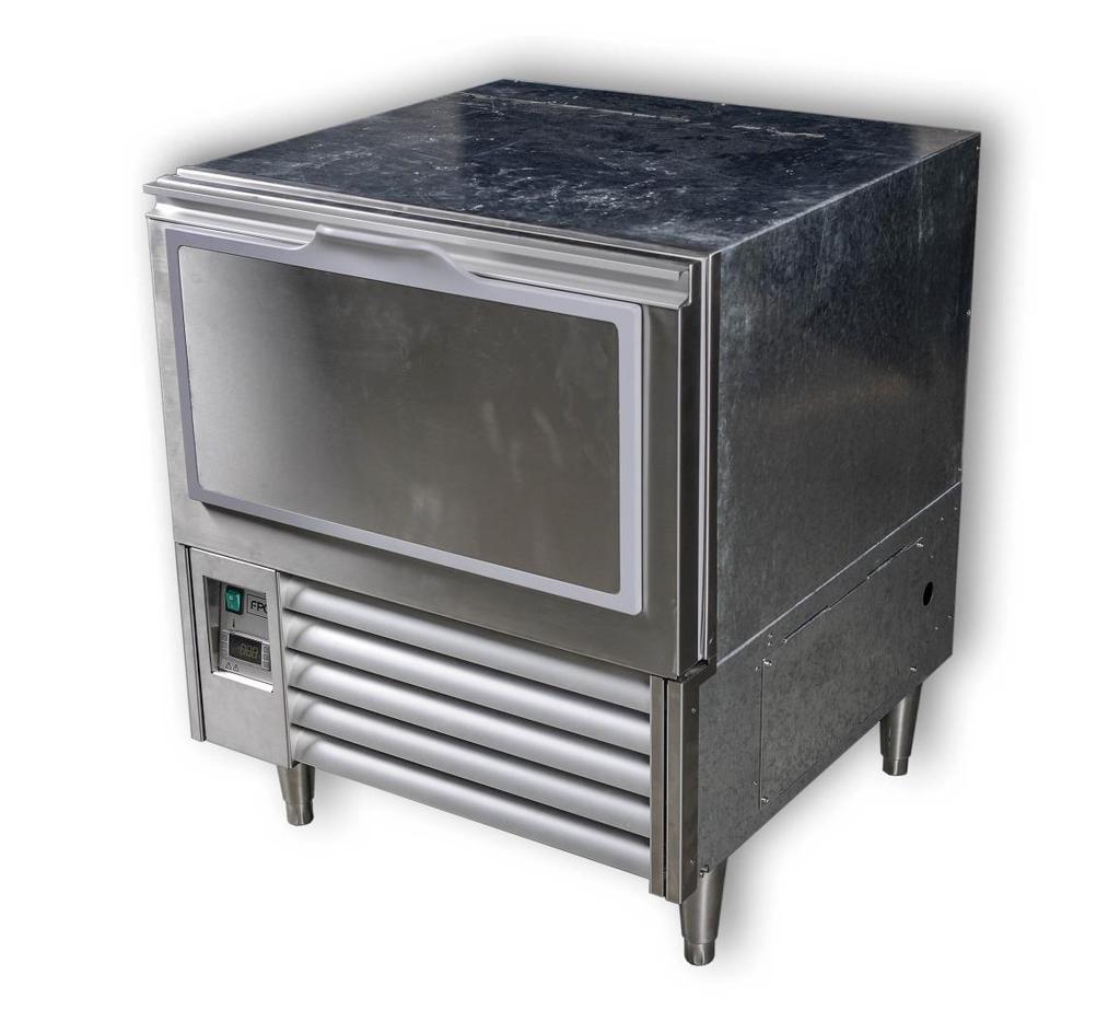
1 Refrigerated Milk Drawer
2 Copyright Septamber 2016 Future Products Group Limited. All rights reserved. No part of this publication may be reproduced, stored in a retrieval system, or transmitted in any form or by any means, electronic, mechanical, photocopying, recording or otherwise, without the prior written permission of Future Products Group Ltd. Part No Rev. B September Refrigerated Milk Drawer
3 Table of Contents INTRODUCTION... 6 Welcome... 6 Future Products Group (FPG)... 6 Guidance and Help... 6 Warranty... 6 Warranty Period... 6 Liability Exceptions... 7 Specific Exclusions... 7 Assessment... 7 Time Limit... 7 Caution... 7 OPERATION... 8 Cabinet Features... 8 Large Capacity... 8 Adjustable Guides... 8 Access Flap... 8 Control Panels... 9 Temperature Controller... 9 Preparation... 9 Load the Drawer... 9 Power Supply Close the Drawer Turn on Main Switch Operating Routines After Hours Cleaning De-frost Cycle TROUBLE SHOOTING Fault Alarm Procedure Dixell CA Fault CLEANING Cautions Power Water IL-C-DRW-A Future Products Group
4 Exterior Plastic and Metal Surfaces Drawer Runners Louvers Pre-filter Interior Empty the Drawer Lift Out Plastic Guides Lift Out Sloping Base Tray Lift Out the Baffle Plate Cleaning Routines Schedules Removable Filter Condenser Radiator Inspection Correction INSTALLATION Regulations Compliance with Local Requirements Setting Up Unpacking Positioning the Cabinet Brace Rail Template Condensate Drain Cabinet Preparation Power Supply and Earthing Connection Terminals Isolation Mains Lead Lead Replacement SERVICING Control Gear Control Gear Location Control Gear Chassis Heating Element Drawer Catch Adjustment Part No Rev. B September Refrigerated Milk Drawer
5 Refrigeration Caution Removable Filters Condenser Radiator Access to Refrigeration Equipment Evaporator Access Evaporator Fans Temperature Probes Temperature Regulator XR40CX XR40CX Key Functions XR40CX LED Functions XR40CX Display the Set-point XR40CX Start a Manual Defrost FPG Settings Dixell Default Settings XR40CX Hot Key XR40CX Alarm Signals XR40CX Alarm Recovery XR40CX Connections SPECIFICATIONS Mechanical Electrical Controller Settings Changes from Dixell Defaults XR40CX Settings NOTE Compliance Safety Aspects Operational Safety Refrigeration Performance Improvements On-going Development ELECTRICAL CIRCUIT DIAGRAMS Model: IL-C-DRW-A SPARE PARTS Cabinet Serial Number MECHANICAL DRAWINGS Model: IL-C-DRW-A IL-C-DRW-A Future Products Group
6 Welcome REFRIGERATED CABINETS - INTRODUCTION INTRODUCTION Future Products Group (FPG) Welcome to the world of FPG! Our products are designed and engineered to give you the optimal performance that you deserve with innovative visual merchandising appeal. We are confident that you will be delighted with your state of the art inline food service cabinet, and that it will become a valued appliance in your store. Guidance and Help Any new appliance can seem very complex and confusing at first glance. To ensure you receive the utmost benefit from your new inline cabinet, there are two things you can do. Before operating the cabinet, please read the instruction book carefully and follow its recommendations. The time taken will be well spent. These instructions both general and technical tell you how to operate and look after your inline food service cabinet so that you can receive the full benefits that this cabinet has to offer. These instructions cannot, however, cover all eventualities. If you are unsure of any aspect of the installation, instructions or performance of your cabinet, contact your dealer promptly or contact us via to support@fpgworld.com. Warranty REFRIGERATED CABINETS - INTRODUCTION Warranty Period Future Products Group Limited warrants, to the original purchaser of an FPG manufactured food service cabinet that for ONE YEAR (12 months), from the date of purchase, any defect in workmanship or material resulting in the product malfunctioning while under correct use will be rectified. The warranty is extended to THREE YEARS (36 months), for refrigeration condenser units. Conditions apply, see Liability Exceptions. Liability under this warranty is limited to replacing or repairing a part, without charge. Continued on next page Part No Rev. B September Refrigerated Milk Drawer
7 Warranty cont. REFRIGERATED CABINETS - INTRODUCTION Liability Exceptions Liability under this warranty does not include: Any loss, or damage or expenses directly or indirectly arising from use or inability to use the product or from any other cause. Any part of the cabinet which has been subject to misuse, neglect, alteration, incorrect installation, accident, or damage caused by transportation, use of abrasive or caustic chemicals, flooding, fire or acts of God. Damage, resulting from failure to have the cabinet regularly serviced every three months by a refrigeration engineer. NB: You will be required to provide copies of service records in the event of compressor failure. Any damage or malfunction resulting from the use of non-fpg supplied spare parts. Specific Exclusions The following are specifically excluded from warranty: Breakage of glass or plastic components or the replacement of gaskets. Maladjustment of the electronic refrigeration controller, by an unqualified person. Failure resulting from a lack of routine compressor / radiator cleaning. Failure to re-assemble the cabinet correctly after cleaning. Fair wear and tear. Assessment The liability under this warranty is dependent on an assessment by FPG, to determine the defect in workmanship or materials. Time Limit FPG does not guarantee that any service to be performed under this warranty will be carried out within any particular time limit. Caution No warranty claim will be accepted unless authorised by FPG prior to commencement of service. IL-C-DRW-A Future Products Group


8 OPERATION Cabinet Features REFRIGERATED CABINETS - OPERATION Large Capacity The drawer has a large storage capacity. It can be configured for an asortment of product packaging. Adjustable Guides The inclined, gravity feed base has adjustable guides, so that products can be consistently organised. The products must be lifted into the access flap section, so that spaces are retained for ease of replacement. Access Flap The quick access front flap enables easy removal of product, without needing the drawer to be opened. This avoids interference with the operator space behind the counter. Part No Rev. B September Refrigerated Milk Drawer


9 Controls REFRIGERATED CABINETS - OPERATION Control Panels The control on the front of the cabinet is fitted with: A mains Power Switch A refrigeration controller Temperature Controller Only to be adjusted by a qualified service technician. The controller regulates the cabinet temperature and controls the automatic defrost cycles. The display indicates the temperature of the returned air, entering the cooling coil, which will be very close to the internal temperature of the cabinet. The refrigeration gas pressure is also monitored, to protect the compressor from damage resulting from a blocked radiator or loss of gas. Preparation REFRIGERATED CABINETS - OPERATION Load the Drawer Pull the drawer forward to load it with pre-chilled containers of milk, and other products. Place a selection of products in the easy-access flap section. The cabinet is designed to maintain the temperature of pre-chilled product at between 2 and 4 C. It is not a refrigerator, and consequently, if warm product is introduced, there could be a considerable delay before the temperature falls to the normal operating level. Continued on next page IL-C-DRW-A Future Products Group

10 Preparation cont. REFRIGERATED CABINETS - OPERATION Power Supply Ensure that power is connected to the cabinet. Close the Drawer It is important to keep the drawer closed. If the drawer is not fully closed, an even temperature will not be maintained within the cabinet. Use the front flap to access product. Opening it has little effect on product temperature, but it is recommended to close it after removing product. Turn on Main Switch Turn on the main power switch, as shown earlier. The refrigeration condenser, and the evaporator and drawer fans will run. The temperature controller is pre-set to maintain the drawer temperatures at 2-4 C. It should not need adjustment. Operating Routines REFRIGERATED CABINETS - OPERATION After Hours Ideally, cabinets should not be turned off after hours. If the cabinet is turned off, move the products to cool storage, and allow the cabinet to run for about half an hour before replacing the pre-chilled products. Cleaning It is recommended to clean the cabinet at the end of the working day, since it needs to be shut down for this. Once the cleaning is finished, turn the cabinet on again and let it cool down before re-loading chilled product. De-frost Cycle The cabinet will de-frost automatically every four hours, starting from when the cabinet is first turned on. If defrost is wanted at a particular time, you must turn on the cabinet four hours before the first defrost required. The cabinet should NOT be temperature tested within ½ hour of a de-frost programme being completed. If you suspect that the defrost system is not working properly, have it checked by a qualified service person. Operators must not attempt to adjust the refrigeration controller. Part No Rev. B September Refrigerated Milk Drawer
11 TROUBLE SHOOTING FAULT POSSIBLE CAUSE REMEDY Cabinet does not operate/start Cabinet does not reach correct temperature Excess external condensation Drawer hard to open The mains isolating switch on the wall, circuit breaker or fuses are off at the power board High pressure switch tripped Low pressure switch tripped The power switch on the cabinet is OFF The power switch is faulty The drawer is open Ventilation grills are blocked Evaporator coil fins blocked Thermostat needs adjustment Ambient temperature > 25 C Damaged drawer seal Evaporator coil iced up Condenser radiator blocked Controller faulty Temperature probe damaged Auto defrost faulty Fans not operating Frame heating is not working Debris in track Drawer runner damaged Turn isolating switch circuit breaker or fuses on Switch cabinet off and on. Clean condenser and radiator Check gas pressure Turn the power switch ON Have the switch replaced Close drawer and re-test temperature after thirty minutes Vacuum or remove blockage Clean coil fins of food etc. Adjust controller Adjust store air conditioning Replace drawer seal De-ice coil Remove dust and debris Replace Dixell controller Replace temperature probe Have defrost settings checked Have fans checked/replaced Check/replace power supply Clean door tracks (see cleaning) Have runner replaced Service Personnel Only The table entries in italics indicate actions to be taken only by qualified Service Personnel. IL-C-DRW-A Future Products Group
12 Fault Alarm Procedure REFRIGERATED CABINETS - TROUBLE SHOOTING Dixell CA Fault If a CA fault alarm appears on the Dixell controller screen, take the following action: 1. Turn off the power supply to the cabinet 2. Clean the condenser pre-filter or the condenser coil if the cabinet is not equipped with a pre-filter 3. Turn on the power supply to the cabinet 4. If the cabinet does not cool, or if the CA fault alarm returns within 24Hrs, call for service. Part No Rev. B September Refrigerated Milk Drawer


13 CLEANING Cautions REFRIGERATED CABINETS - CLEANING Power ALWAYS TURN THE POWER SUPPLY OFF BEFORE CLEANING. Water THIS UNIT IS NOT WATERPROOF. DO NOT USE A WATER JET SPRAY TO CLEAN THE INTERIOR OR EXTERIOR OF THIS CABINET. Exterior REFRIGERATED CABINETS - CLEANING Plastic and Metal Surfaces Plastic or stainless steel surfaces should be cleaned with hot soapy water or a good quality glass cleaner. DO NOT clean surfaces with abrasive pads or cleaners as surfaces will be damaged. Drawer Runners With the drawer fully open, vacuum or brush away any debris in the runners, located on each side. Louvers Use a vacuum cleaner to remove dust and fluff from the ventilation louvers. This will maintain the refrigeration efficiency, and prevent overheating. Pre-filter The pre-filter should be removed and cleaned regularly. Hinge down the front panel to lift out the filter. Knock off loose dirt and wash the filter in warm soapy water, as required. IL-C-DRW-A Future Products Group


14 Interior REFRIGERATED CABINETS - CLEANING Empty the Drawer Do NOT remove the drawer for routine cleaning. Open the drawer fully, and remove all products. Lift Out Plastic Guides The plastic guides just rest on the inclined base tray, and can be lifted out for cleaning. Individual sections may be unclipped from the acrylic strip if required. The acrylic strip must be toward the front of the drawer, when re-assembled. Lift Out Sloping Base Tray Note the position of the tray tabs and chassis slots. The tray will slope down towards the front, when inserted correctly. Lift Out the Baffle Plate With the flap open, lift out the baffle plate. Sweep out, or use a vacuum cleaner, to remove any debris from inside the drawer. A Wet-and-Dry vacuum cleaner should be used, since there is likely to be some water in the drawer. Part No Rev. B September Refrigerated Milk Drawer

15 Cleaning Routines REFRIGERATED CABINETS - CLEANING Schedules Regular cleaning schedules are required to maintain optimum performance. Failure to carry out routine cleaning/servicing schedules will void the warranty on the refrigeration equipment. Removable Filter The air pre-filter must be kept clean, to maintain efficient refrigeration performance. The filter is easily removed by hinging down the spring-loaded front panel. Use a vacuum cleaner to remove dust and fluff, and wash if necessary. Condenser Radiator For efficient refrigeration performance, the condenser radiator must be kept clean, (see Servicing, Condenser Radiator). Regular vacuuming will prevent a build-up of dust and fluff, but periodic cleaning of the fins, by a refrigeration engineer, is mandatory. Inspection As part of the cleaning routine, the controls, mechanical parts and electrical wiring should be inspected for damage, deterioration or need of adjustment. Correction If any small faults are found, have them attended to promptly by a competent serviceman. Don t wait until they cause a complete breakdown. IL-C-DRW-A Future Products Group


.")
16 INSTALLATION Regulations REFRIGERATED CABINETS - INSTALLATION Compliance with Local Requirements It is very important that your cabinet is installed correctly and that the operation is correct before use. Installation must comply with local electrical, health & safety and hygiene requirements. Setting Up REFRIGERATED CABINETS - INSTALLATION Unpacking Unpack and check unit for damage and report any damage to the carrier and supplier. Report any deficiencies to your supplier. The cabinet is supplied fully assembled. Positioning the Cabinet Ensure the cabinet location and any bench cutouts are made to the precise measurements shown in the Mechanical Drawings. Position the cabinet in its allocated working position. Adjust each foot to set the height, ensuring the cabinet is level from side to side and front to back. (If this is not carried out, water may accumulate in the cabinet well, and uneven temperature distribution could also occur). Brace Rail To ensure stability of the cabinet, when the drawer is open, the provided brace rail must be fixed to the joinery, behind the cabinet. The legs must be adjusted before the brace rail and rear panel are set to their correct heights. Template To ensure correct alignment of the brace rail and cabinet, the side access panel can be removed and used as a template. With the template on the floor, set the height of the brace rail and screw it to the joinery. Loosen the fixing screws on the rear panel, and use the template to set its height. Continued on next page Part No Rev. B September Refrigerated Milk Drawer


17 Setting Up cont. REFRIGERATED CABINETS - INSTALLATION Condensate Drain The condensate drain outlet must be connected to a suitable drain. Exit holes are provided underneath, and on either side of the cabinet. A P-trap must be included in the piping, to prevent contaminated air from entering the cabinet. Cabinet Preparation Remove all tapes, ties and packers, used to prevent movement during transit. Power Supply and Earthing The cabinet is supplied with a mains cable and three-pin plug. If the cabinet is to be hard wired, this must only be done by a suitably qualified person. Before connecting to the power supply, check that the local supply is correct to that shown on the rating plate, located on the rear of the cabinet. Connection Terminals The connection terminals are located behind a removable panel. WARNING-THIS APPLIANCE MUST BE EARTHED/GROUNDED Isolation If the cabinet is not connected by a plug and socket, but is hard wired to the mains supply, a means of isolation must be provided. If a plug and socket are used, they should still be accessible after the cabinet is installed. Mains Lead REFRIGERATED CABINETS - INSTALLATION Lead Replacement If damaged, the mains lead must ONLY be replaced by a qualified service person. IL-C-DRW-A Future Products Group


18 SERVICING Control Gear REFRIGERATED CABINETS - SERVICING Control Gear Location All control gear is located in the box behind the mains switch. Hinge down the spring loaded front panel to access it. Remove two screws to release the back panel. Control Gear Chassis The chassis houses the connecting blocks for the refrigeration equipment, a fuse for the low power items, and a 24V dc power supply for the anticondensation heating element. See the circuit diagram for details. The mains switch and refrigeration controller are mounted on the front panel. Heating Element An anti-condensation heating element is fitted inside frame of the cabinet. The element is made from insulated resistance wire, and should last the life of the cabinet. It is rated at 24V, 26W and is supplied from the 24V dc power supply. Drawer Catch Adjustment The male half of the drawer catch can be adjusted by turning the screw shown. Turn clockwise to increase latch strength. Part No Rev. B September Refrigerated Milk Drawer


19 Refrigeration REFRIGERATED CABINETS - SERVICING Caution DO NOT attempt to service the refrigeration equipment without isolating the cabinet at the main switch or unplugging it from the wall. Removable Filters The cabinet is fitted with a removable filter, which will catch most of the dust and fluff, before it reaches the condenser radiator. This are easily removed and should be cleaned regularly. Shake or vacuum off accumulated debris and wash in warm soapy water. Condenser Radiator For efficient refrigeration performance, the condenser radiator must be kept clean. Failure to do this will lead to a build-up of dust, and restricted airflow will prevent the unit from working properly. The compressor may overheat and the cabinet temperature may rise. Be careful not to bend or damage the soft aluminium fins when vacuuming the radiator. If the fins are flattened, airflow will be restricted and overheating will result. Regular vacuuming will prevent a build-up of dust and fluff, but three monthly service checks, by a refrigeration engineer, are mandatory. These should include cleaning the condenser radiator using compressed air. Access to Refrigeration Equipment Removable panels, on the right and rear of the cabinet, provide further access to the refrigeration equipment. Continued on next page IL-C-DRW-A Future Products Group


20 Refrigeration cont. REFRIGERATED CABINETS - SERVICING Evaporator Access The drawer must be removed to access the evaporator fans, coil and temperature probes. Pull the drawer fully forward and lift upwards to disengage the runners. The fan panel is secured with four screws. Evaporator Fans The fans are hard-wired, but the panel can be rested on the runners whilst servicing. Take care not to trap the cables when replacing the panel. Temperature Probes There are two temperature probes on the cooling coil. The defrost termination probe is located between the fins, at the top of the coil. The temperature control probe is supported in free air, below the coil. It responds to the return air, (air-on) temperature. Continued on next page Part No Rev. B September Refrigerated Milk Drawer

21 Refrigeration cont. REFRIGERATED CABINETS - SERVICING Temperature Regulator XR40CX Model XR40CX is a microprocessor based controller. It is has two NTC probe inputs, the first one for temperature control, the second one, located onto the evaporator, to control the defrost termination temp. The indicated temperature will be slightly higher than the temperature inside the drawer, because the refrigeration condenser is controlled in response to the temperature of the return air entering the cooling coils. The HOT KEY output allows one to programme the controller by means the HOT KEY programming keyboard. The instrument is fully configurable through special parameters that can be easily programmed through the keyboard. XR40CX Compressor Control The regulation is performed according to the temperature measured by the thermostat probe with a positive differential from the set point: if the temperature increases and reaches set point plus differential the compressor is started and then turned off when the temperature reaches the set point value again. In case of a fault in the thermostat probe the start and stop of the compressor are timed through parameters COn and COF. ON Time XR40CX Defrost Control Parameters are used to control the interval between defrost cycles (IdF), its maximum length (MdF) and two defrost modes: timed or controlled by the evaporator s probe (P2P). In this cabinet, the start of the defrost cycle is timed, but the cycle will be terminated as soon as the defrost probe reaches the pre-determined temperature. At the end of defrost dripping time is started, its length is set in the FSt parameter. With FSt =0 the dripping time is disabled Continued on next page IL-C-DRW-A Future Products Group
 To start a manual defrost")
22 Refrigeration cont. REFRIGERATED CABINETS - SERVICING XR40CX Key Functions KEY FUNCTION To display target set point; in programming mode it selects a parameter or confirm an operation (DEF) To start a manual defrost (UP): To see the max. stored temperature; in programming mode it browses the parameter codes or increases the displayed value (DOWN): To see the min stored temperature; in programming mode it browses the parameter codes or decreases the displayed value To switch the instrument off, if onf = off. Not enabled To lock & unlock the keyboard To enter into programming mode To return to the temperature display mode XR40CX LED Functions LED MODE FUNCTION ON Flashing ON Flashing ON ON ON ON Flashing Compressor enabled Anti-short cycle delay enabled Defrost enabled Drip time in progress An alarm is occurring Continuous cycle is running Energy saving enabled Measurement unit Programming phase Continued on next page Part No Rev. B September Refrigerated Milk Drawer
23 Refrigeration cont. REFRIGERATED CABINETS - SERVICING XR40CX Min & Max Recorded Temperature Press and release the key. Lo will be displayed followed by the minimum temperature recorded. Press the key again or wait 5s to restore the normal display. Press and release the key. Hi will be displayed followed by the maximum temperature recorded. Press the key again or wait 5s to restore the normal display. XR40CX Reset Max/Min Temperature Memory Press the SET key for more than 3s, while the max. or min. temperature is displayed. (rst message will be displayed) To confirm the operation the rst message starts blinking and the normal temperature will be displayed. XR40CX Display the Setpoint To show the set-point value, press and immediately release the SET key. Press and immediately release the SET key or wait for 5 seconds to display the probe temperature again. XR40CX Change the Set-point To change the set-point value, press the SET key for more than 2 seconds; The value of the set-point will be displayed and the C or F LED starts blinking; To change the set value push the or arrows within 10s. To memorise the new set-point value push the SET key again or wait 10s. XR40CX Start a Manual Defrost To start a manual defrost, press the (DEF) key for more than 2 seconds. XR40CX Programming Mode Enter the Programming mode by pressing the (the C or F LED starts blinking). keys for 3s Use the or keys to select the required parameter. Press the key to display its value. Use the or keys to change its value. Press to store the new value and move to the following parameter. To exit Programming mode, press or wait 15s without pressing a key. NOTE: the set value is stored even when the procedure is exited by waiting for the time-out to expire. Continued on next page IL-C-DRW-A Future Products Group
24 Refrigeration cont. REFRIGERATED CABINETS - SERVICING XR40CX The Hidden Menu The hidden menu includes all the parameters of the instrument. TO ENTER THE HIDDEN MENU Enter the Programming mode by pressing the keys for 3s, (the C or F LED starts blinking). Release the keys, then press the keys again, for more than 7s. The Pr2 label will be displayed immediately followed from the Hy parameter. NOW YOU ARE IN THE HIDDEN MENU. Select the required parameter. Press the key to display its value Use or to change its value. Press to store the new value and move to the following parameter. To exit: Press or wait 15s without pressing a key. NOTE 1: If no parameter is present in Pr1, after 3s the nop message is displayed. Keep the keys pushed till the Pr2 message is displayed. NOTE 2: The set value is stored even when the procedure is exited by waiting for the time-out period to expire. TO MOVE A PARAMETER FROM THE HIDDEN MENU TO THE FIRST LEVEL AND VICEVERSA. Each parameter present in the HIDDEN MENU can be removed or put into THE FIRST LEVEL (user level) by pressing In HIDDEN MENU when a parameter is present in the First Level the decimal point is shown. XR40CX Locking and Unlocking the Keyboard To lock the keyboard, press the keys for more than 3 s. The POF message will be displayed, followed by the previous temperature display. If a key is pressed more than 3s the POF message will be displayed. To unlock the keyboard, press the message is displayed. keys for more than 3s, till the Pon Continued on next page Part No Rev. B September Refrigerated Milk Drawer
25 Refrigeration cont. REFRIGERATED CABINETS - SERVICING FPG Settings Note that the following settings are Dixell factory defaults. Refer to the Specification section for the correct FPG settings for your cabinet. Dixell Default Settings Label Name Range Default Set Set point LS US -5.0 Hy Differential 0, C/ F 2.0 LS Minimum set point -50 C SET/-58 F SET US Maximum set point SET 110 C/ SET 230 F 110 Ot Thermostat probe calibration C / F 0.0 P2P Evaporator probe presence n=not present; Y=pres. Y OE Evaporator probe calibration C / F 0.0 P3P Third probe presence n=not present; Y=pres. n O3 Third probe calibration C / F 0 P4P Fourth probe presence n=not present; Y=pres. n O4 Fourth probe calibration C / F 0 OdS Outputs delay at start up min 0 AC Anti-short cycle delay 0 50 min 1 rtr P1-P2 percentage for regulation (100=P1, 0=P2) 100 CCt Continuous cycle duration h 0.0 CCS Set point for continuous cycle ( ,0 C) ( F) -5 COn Compressor ON time with faulty probe min 15 COF Compressor OFF time with faulty probe min 30 CF Temperature measurement unit C F C res Resolution in=integer; de= dec.point de Lod Probe displayed P1;P2 P1 red2 X-REP display P1 - P2 - P3 - P4 - SEt - dtr P1 dly Display temperature delay min (10 sec.) 0 dtr P1-P2 percentage for display tdf Defrost type EL=el. heater; in= hot gas EL dfp Probe selection for defrost termination np; P1; P2; P3; P4 P2 dte Defrost termination temperature C 8 IdF Interval between defrost cycles ore 6 MdF (Maximum) length for defrost min 30 dsd Start defrost delay 0 99min 0 dfd Displaying during defrost rt, it, SEt, DEF it dad MAX display delay after defrost min 30 Fdt Draining time min 0 dpo First defrost after start-up n=after IdF; y=immed. n daf Defrost delay after fast freezing 0 23h e ALc Temperature alarms configuration re= related to set; Ab = absolute Ab ALU MAXIMUM temperature alarm Set C; Set 230 F 110 ALL Minimum temperature alarm C Set/ -58 F Set Continued on next page IL-C-DRW-A Future Products Group
26 Refrigeration cont. REFRIGERATED CABINETS - SERVICING Dixell Default Settings cont. Label Name Range Default AFH Differential for temperat. alarm recovery (0,1 C 25,5 C) (1 F 45 F) 1 ALd Temperature alarm delay min 15 dao Delay of temperature alarm at start up 0 23h e AP2 Probe for temperat. alarm of condenser np; P1; P2; P3; P4 P4 AL2 Condenser for low temperat. alarm ( C) ( F) -40 AU2 Condenser for high temperat. alarm ( C) ( F) 110 AH2 Differ. for condenser temp. alar. recovery [0,1 C 25,5 C] [1 F 45 F] 5 Ad2 Condenser temperature alarm delay (min.), 255=nU 15 da2 Delay of cond. temper. alarm at start up h 50 1,3 bll Compressor OFF for condenser low temperature alarm n(0) - Y(1) n AC2 Compressor OFF for condenser high temperature alarm n(0) - Y(1) n i1p Digital input polarity op=opening; CL=closing cl i1f Digital input configuration EAL, bal, PAL, dor; def; Htr, AUS EAL did Digital input alarm delay 0 255min 5 Nps Number of activation of pressure switch odc Compress status when open door no; Fan; CPr; F_C no rrd Regulation restart with door open alarm n Y y HES Differential for Energy Saving (-30 C 30 C) (-54 F 54 F) 0 Adr Serial address PbC Kind of probe Ptc; ntc ntc onf on/off key enabling nu, off; ES nu dp1 Room probe display dp2 Evaporator probe display dp3 Third probe display dp4 Fourth probe display rse Set operating value actual set -- rel Software release Ptb Map code XR40CX Hot Key To program the controller from a Hot Key: Turn OFF the instrument. Insert a programmed Hot Key into the 5 PIN socket and then turn the Controller ON. The parameter list of the Hot Key is automatically downloaded into the Controller memory, the dol will blink, followed a by a flashing End. After 10 seconds the instrument will restart working with the new parameters. Remove the Hot Key. NOTE the message Err is displayed if programming fails. In this case turn the unit off and then on again, if you want to restart the download again, or remove the Hot Key to abort the operation. Continued on next page Part No Rev. B September Refrigerated Milk Drawer
27 Refrigeration cont. REFRIGERATED CABINETS - SERVICING XR40CX Alarm Signals Message Cause Outputs P1 Room probe failure Compressor output acc. to par. Con and COF P2 Evaporator probe failure Defrost end is timed P3 Third probe failure Outputs unchanged P4 Fourth probe failure Outputs unchanged HA Maximum temperature alarm Outputs unchanged. LA Minimum temperature alarm Outputs unchanged. HA2 Condenser high temperature It depends on the Ac2 parameter LA2 Condenser low temperature It depends on the bll parameter da Door open Compressor according to rrd EA External alarm Output unchanged. CA Serious external alarm (i1 F=bAL) All outputs OFF. CA Pressure switch alarm (i1 F=PAL) All outputs OFF XR40CX Alarm Recovery Probe alarms P1, P2, P3 and P4 start some seconds after the fault in the related probe; they automatically stop some seconds after the probe restarts normal operation. Check connections before replacing the probe. Temperature alarms HA, LA, HA2 and LA2 automatically stop as soon as the temperature returns to normal values. Alarms EA and CA (with i1 F=bAL) recover as soon as the digital input is disabled. Alarm CA (with i1 F=PAL) recovers only by switching off and on the instrument. XR40CX Other Messages Message Pon PoF nop noa Cause Keyboard unlocked. Keyboard locked In programming mode: none parameter is present in Pr1 On the display or in dp2, dp3, dp4: the selected probe is not enabled No alarm is recorded. XR40CX Connections IL-C-DRW-A Future Products Group
28 Mechanical REFRIGERATED CABINETS - SPECIFICATIONS SPECIFICATIONS IL-C-DRW-A001 Height overall mm 845 CABINET MODEL Adjustment mm mm Width mm 700 Depth mm 789 Dry Weight kg 110 Cabinet Well Material Stainless Steel Storage Drawers 1 Drawer Capacity Refrigerant Refrigerant Charge Climatic Class & IP 24 x 2 litre bottles R134A See cabinet rating label Cabinets are suitable for class N climates and have an IP 22 rating Electrical REFRIGERATED CABINETS - SPECIFICATIONS IL-C-DRW-A001 CABINET MODEL Voltage V 50 Hz 1 Maximum Current 1.46A Peak Power Average Energy Consumption Connection Drawer Temperature, C 336W 0.12kWh/h Three core cable, CEE Plug 2-4 Part No Rev. B September Refrigerated Milk Drawer
29 Controller Settings REFRIGERATED CABINETS - SPECIFICATIONS Changes from Dixell Defaults The following table specifies the controller settings which differ from the Dixell default values. Parameters not listed in this table should remain at the default values specified in the XR40CZ Parameters listed in the Servicing section. XR40CX Settings Parameter Description Unit / range Set Set Point 2 degc Hy Differential 2 degc AC Anti Short Cycle Delay 0 Min C0n Comp On Time - Faulty Probe 4 Min C0F Comp Off Time - Faulty Probe 6 Min dte Defrost Terminate Temp 4 degc IdF Interval Between Defrosts 4 Hrs dfd Display During Defrost DEF rt, it, Set, DEF AP2 Probe For High Discharge Temp Alarm np np, P1, P2, P3, P4 i1p Digital Input Polarity op cl, op i1f Digital Input Configuration bal EAL, bal, PAL, dor, def, AUS, Htr, ES did Digital Input Alarm Delay 1 Min Nps Number Of Activations Of Pressure Switch NOTE The temperature of the drawer is controlled by the return air probe. IL-C-DRW-A Future Products Group

30 Compliance REFRIGERATED CABINETS - SPECIFICATIONS Safety Aspects These cabinets have been designed to comply with the relevant requirements of the following specifications: AS/NZS 3100 General Requirements for Electrical Equipment AS/NZS 3182 Refrigerated Food Commercial Cabinets AS/NZS 3820 Essential Safety Requirements AS/NZS 4417 Marking of Electrical Products IEC Part 1: Part 2-24: EN Part 1: Part 2: EN Part 3-2: Part 3: Household and Similar Electrical Appliances Safety General Requirements Particular Requirements for Refrigerating Appliances / Ice Cream Appliances and Ice Makers Electromagnetic Compatibility Requirements for Household Appliances, Electric Tools and Similar Apparatus Emissions Immunity - Product Family Standard Electromagnetic compatibility (EMC) Limits - Limits for harmonic current emissions (equipment input current up to and including 16A per phase) Limits - Section 3: Limitations of voltage changes, voltage fluctuations and flicker in public low-voltage supply systems, for equipment with rated current 16A per phase and not subject to conditional connection Operational Safety This appliance is not intended for use by young children or infirm persons, unless they have been adequately supervised by a responsible person, to ensure that they can use the appliance safely. Young children should be supervised, to ensure that they do not play with the appliance. Refrigeration Performance Cabinet Operating Temperature Standard Model Test Conditions +2 to +4 C 25 C Ambient with 60% RH Improvements REFRIGERATED CABINETS - SPECIFICATIONS On-going Development FPG reserves the right to change specifications and construction, as part of ongoing product improvement. Part No Rev. B September Refrigerated Milk Drawer
31 ELECTRICAL CIRCUIT DIAGRAMS Model: IL-C-DRW-A001 Refrigerated Milk Drawer IL-C-DRW-A Future Products Group
32 SPARE PARTS Cabinet Serial Number When ordering spare parts, it is important to quote the Serial Number printed on the label fixed to the control panel. This serial number will enable FPG to trace details of the build specification of your particular cabinet, and hence ensure that spare parts are fully compatible. To satisfy warranty conditions, and ensure optimum performance, use only FPG supplied spare parts. Part Description FPG Part No. Switch DPST 16A 250V Fuse 5A Power supply, 24V 60W Dixell XR40CX digital refrigeration controller NTC temperature probe Low Pressure Switch High pressure switch Drawer Fans NMB 3110KL Condenser unit Danfoss FR6GXN Pre-filter Element Drawer Runners Drawer Latch Product Manual for Refrigerated Milk Drawer Continued on next page Part No Rev. B September Refrigerated Milk Drawer
33 MECHANICAL DRAWINGS Model: IL-C-DRW-A001 IL-C-DRW-A Future Products Group
34 Part No Rev. B September Refrigerated Milk Drawer
35 IL-C-DRW-A Future Products Group

36 Part No Rev. B September 2016
Popcorn Warmer Cabinet
 Popcorn Warmer Cabinet Copyright July 2016 Future Products Group Limited. All rights reserved. No part of this publication may be reproduced, stored in a retrieval system, or transmitted in any form or
Refrigerated Cabinets Square Format
 Refrigerated Cabinets Square Format Copyright December 2017, Future Products Group Limited. All rights reserved. No part of this publication may be reproduced, stored in a retrieval system, or transmitted
Refrigerated Cabinets
 Refrigerated Cabinets Copyright June 2017 Future Products Group Limited. All rights reserved. No part of this publication may be reproduced, stored in a retrieval system, or transmitted in any form or
Inline GN Series Refrigerated Well
 Inline GN Series Refrigerated Well Copyright June 2017 Future Products Group Limited. All rights reserved. No part of this publication may be reproduced, stored in a retrieval system, or transmitted in
Open Front Food & Drinks Cabinet AS/NZS
 Open Front Food & Drinks Cabinet AS/NZS Copyright November 2017 Future Products Group Limited. All rights reserved. No part of this publication may be reproduced, stored in a retrieval system, or transmitted
Refrigerated Cabinets Curved Format
 Refrigerated Cabinets Curved Format Copyright August 2018, Future Products Group Limited. All rights reserved. No part of this publication may be reproduced, stored in a retrieval system, or transmitted
Food & Beverage Cabinet
 Food & Beverage Cabinet Copyright June 2017 Future Products Group Limited. All rights reserved. No part of this publication may be reproduced, stored in a retrieval system, or transmitted in any form or
Refrigerated Cabinets Curved Format
 Refrigerated Cabinets Curved Format Copyright August 2018 Future Products Group Limited. All rights reserved. No part of this publication may be reproduced, stored in a retrieval system, or transmitted
Digital Controller XR70CX. Operating Manual. 5/10 Rev. B
 Digital Controller XR70CX Operating Manual 5/10 Rev. B 139734 Contents General Warnings 3 General Description 3 Regulation 3 Defrost 3 Fans 4 Front Panel Commands 4 Parameters 6 Installation and Mounting
IKEA USA Refrigerated Cabinets
 IKEA USA Refrigerated Cabinets Copyright March 2017 Future Products Group Limited. All rights reserved. No part of this publication may be reproduced, stored in a retrieval system, or transmitted in any
Commercial Freezer Service Manual
 Commercial Freezer Service Manual SOLID DOOR TOP MOUNT REACH-IN PTM49F Please read this manual completely before attempting to install or operate this equipment. TABLE OF CONTENTS 1. FEATURE CHART 1-1.
XR60C ,QVWDOOLQJDQG2SHUDWLQJ,QVWUXFWLRQV. Digital controller with defrost and fans management 1. GENERAL WARNING 4. FRONT PANEL COMMANDS
 Digital controller with defrost and fans management XR60C CONTENTS 1. GENERAL WARNING 1 2. GENERAL DESCRIPTION 1 3. CONTROLLING LOADS 1 4. FRONT PANEL COMMANDS 1 5. TEMPERATURE ALARM AND ITS DURATION RECORDING
dixel Installing and Operating Instructions PRELIMINAY
 . GENERAL WARNING XW6K - AFV PLEASE READ BEFORE USING THIS MANUAL This manual is part of the product and should be kept near the instrument for easy and quick reference. The instrument shall not be used
XR60CX. Installation and Operating Instructions. Digital controller with defrost and fans management. + + To return to the room temperature display.
 Digital controller with defrost and fans management XR60CX CTENTS 1. GENERAL WARNING 1 2. GENERAL DESCRIPTI 1 3. CTROLLING LOADS 1 4. FRT PANEL COMMANDS 1 5. MAX & MIN TEMPERATURE MEMORIZATI 1 6. MAIN
Commercial Refrigerator Service Manual
 Commercial Refrigerator Service Manual SOLID DOOR TOP MOUNT REACH-IN PTM49R Please read this manual completely before attempting to install or operate this equipment. TABLE OF CONTENTS 1. FEATURE CHART
Copyright July 2017 Future Products Group Limited. All rights reserved.
 Heated Cabinets Copyright July 2017 Future Products Group Limited. All rights reserved. No part of this publication may be reproduced, stored in a retrieval system, or transmitted in any form or by any
dixel Installing and Operating Instructions
 XW20K AND T620 V620 CX620 1. GENERAL WARNING PLEASE READ BEFORE USING THIS MANUAL This manual is part of the product and should be kept near the instrument for easy and quick reference. The instrument
Copyright September 2018 Future Products Group Limited. All rights reserved.
 Ambient Cabinets Copyright September 2018 Future Products Group Limited. All rights reserved. No part of this publication may be reproduced, stored in a retrieval system, or transmitted in any form or
OPERATING INSTRUCTIONS ULTF 80 / 220 / 320 / 420
 OPERATING INSTRUCTIONS ULTF 80 / 220 / 320 / 420 INDEX........................................................... PAGE Before using the appliance...............................................................
Ambient Cabinets Curved Format
 Ambient Cabinets Curved Format Copyright September 2018 Future Products Group Limited. All rights reserved. No part of this publication may be reproduced, stored in a retrieval system, or transmitted in
XH50P - XH55P Temperature/relative humidity probe with RS485 serial line
 XH50P - XH55P Temperature/relative humidity probe with RS485 serial line 1. GENERAL WARNINGS 1.1 PLEASE READ BEFORE USING THIS MANUAL This manual is part of the product and should be kept near the instrument
XW40K AND T620T - T620 V620 CX620
 XW40K AND T620T - T620 V620 CX620 1 GENERAL WARNING... 1 2 GENERAL DESCRIPTI... 1 3 CTROLLING LOADS... 1 4 SPECIAL FUNCTIS... 1 5 KEYBOARDS... 1 6 AUTOMATIC KEYBOARD LOCK (LY FOR T620T)... 2 7 CTROLLER
 dixel Installing and Operating Instructions 1592027050 Digital controller for medium-low temperature refrigeration applications XW60L 1. GENERAL WARNING 1.1 PLEASE READ BEFORE USING THIS MANUAL This manual
User Instructions Lab* Frost. Ultra Low Temperature Freezers Model LAB
 User Instructions Lab* Frost Ultra Low Temperature Freezers Model LAB SAFETY INFORMATIONS The LAB freezers contains environmentally friendly but flammable refrigerants. It means danger of explosion if
Top Mount Full Length Swinging Doors
 Top Mount Full Length Swinging Doors *Shown in FT103SD3 model Model FT77SD FT103SD3 FT138SD Width 77 103 138½ Depth 32 32 32 Height 86 ½ 86 ½ 86 ½ Volume/cu. Ft. 77 103 140 Doors 3 3 4 Door Size 23 x 66
Dixell Installing and Operating Instructions release 7.0
 XR160C - XR160D - XR170C - XR170D - XR162C - XR172C CONTENTS 1. GENERAL WARNING 2 1.1 Please read before using this manual 2 1.2 Safety Precautions 2 2. GENERAL DESCRIPTION 2 3. CONTROLLING LOADS 2 3.1
XR77CX. dixel Installing and Operating Instructions Digital controller for medium-low temperature refrigeration applications
 Digital controller for medium-low temperature refrigeration applications XR77CX 1. GENERAL WARNING 1.1 PLEASE READ BEFORE USING THIS MANUAL This manual is part of the product and should be kept near the
Time KEY COMBINATIONS: + To lock & unlock the keyboard. + To enter in programming mode. + To return to the room temperature display. 4.
 Digital controller for medium-low temperature refrigeration applications XW40L 1. GENERAL WARNING 1.1 PLEASE READ BEFORE USING THIS MANUAL This manual is part of the product and should be kept near the
XWA11V. Walk-In Temp / Door /Alarm / Light Module
 XWA11V Walk-In Temp / Door /Alarm / Light Module 1. GENERAL DESCRIPTION Model XWA11V, 100x64 mm format, is a microprocessor-based controller, suitable for temperature monitoring and alarming in a walk-in
XW70L. Digital controller for medium-low temperature refrigeration applications AUX 1. GENERAL WARNING 2. GENERAL DESCRIPTION 3.
 Digital controller for medium-low temperature refrigeration applications XW70L 1. GENERAL WARNING 1.1 PLEASE READ BEFORE USING THIS MANUAL This manual is part of the product and should be kept near the
XWA11V-KIT Walk-In Temp / Door /Alarm / Light Module with Mounting Box and Wiring
 XWA11V-KIT Walk-In Temp / Door /Alarm / Light Module with Mounting Box and Wiring 1. GENERAL DESCRIPTION Model XWA11V-KIT, 100x64 mm format, is a microprocessor based light and alarm management controller,
Operating Instructions XWA11V XWA11V. Walk-In Temp / Door /Alarm / Light Module
 XWA11V Walk-In Temp / Door /Alarm / Light Module 1. GENERAL DESCRIPTION Model XWA11V, 100x64 mm format, is a microprocessor-based controller, suitable for temperature monitoring and alarming in a walk-in
Operating Instructions XWA11V. XWA11V-KIT Walk-In Temp / Door /Alarm / Light Module with Mounting Box and Wiring
 XWA11V-KIT Walk-In Temp / Door /Alarm / Light Module with Mounting Box and Wiring 1. GENERAL DESCRIPTION Model XWA11V-KIT, 100x64 mm format, is a microprocessor based light and alarm management controller,
Rev 0 09-FEB XR75CX Digital Controller for Medium-Low Temperature Refrigeration Applications Installation and Operation Manual
 026-1210 Rev 0 09-FEB-2011 XR75CX Digital Controller for Medium-Low Temperature Refrigeration Applications Installation and Operation Manual Retail Solutions 3240 Town Point Drive NW Suite 100 Kennesaw,
MINITOP Refrigerated Self-Service Display underneath
 MINITOP Refrigerated Self-Service Display underneath Instructions of use and maintenance page 2 Electric and refrigerating diagrams page 3 Manual of the thermostat page 4 Spare parts page 6 Rue Charles
Instructions of use and maintenance page 2 Electric and refrigerating diagrams page 3 Manual of the thermostat page 4 Spare parts page 6
 INOUK Upright refrigerated display Instructions of use and maintenance page 2 Electric and refrigerating diagrams page 3 Manual of the thermostat page 4 Spare parts page 6 Rue Charles Hermite Z.I. des
OMNITOP Refrigerated Display with Ventilated Cooling
 OMNITOP Refrigerated Display with Ventilated Cooling Instructions of use and maintenance page 2 Electric and refrigerating diagrams page 3 Manual of the thermostat page 4 Spare parts page 6 Rue Charles
Electronic Controller For Refrigeration XLR130 XLR170
 Electronic Controller For Refrigeration XLR130 XLR170 Instructions Manual COOL OOLMATE XLR130C XLR170C INDEX 1. GENERAL WARNING 3 2. GENERAL DESCRIPTION 3 3. CONTROLLING LOADS 3 4. KEYBOARD 5 5. REAL TIME
XH260L XH260V. Dixell Operating instructions TEMPERATURE AND HUMIDITY CONTROLLER 1. GENERAL WARNING
 XH260L XH260V TEMPERATURE AND HUMIDITY CTROLLER 1. GENERAL WARNING 1.1 PLEASE READ BEFORE USING THIS MANUAL This manual is part of the product and should be kept near the instrument for easy and quick
REVERSO. Instructions of use and maintenance page 2 Electric and refrigerating diagrams page 3 Manual of the thermostat page 4-6 Spare parts page 7
 REVERSO Instructions of use and maintenance page 2 Electric and refrigerating diagrams page 3 Manual of the thermostat page 4-6 Spare parts page 7 Rue Charles Hermite Z.I. des Sables BP 59 54110 Dombasle
Rev 1 24-MAY XR75CX Digital Controller for Medium-Low Temperature Refrigeration Applications Installation and Operation Manual
 026-1210 Rev 1 24-MAY-2012 XR75CX Digital Controller for Medium-Low Temperature Refrigeration Applications Installation and Operation Manual Retail Solutions 3240 Town Point Drive NW Suite 100 Kennesaw,
AIR COOLED CHILLERS MODELS: MPCA0005 MPCA0150 INSTALLATION, OPERATION, AND MAINTENANCE MANUAL
 MOTIVAIR COOLING SOLUTIONS AIR COOLED CHILLERS MODELS: MPCA0005 MPCA0150 INSTALLATION, OPERATION, AND MAINTENANCE MANUAL This chiller has been factory run tested to the specified water pressure *****DO
SSGB. EPH Certified to NSF-7 G B. Technical Data Sheet P/N _E. January Data sheet-excel SSGB
 H SSGB Technical Data Sheet P/N 3018921_E EPH Certified to NSF-7 January 2018 F A C D E A G B We reserve the right to change or revise specifications and product design in connection with any feature of
UNDERCOUNTER LABORATORY REFRIGERATORS and FREEZERS Installation, Operation and Maintenance Instructions
 UNDERCOUNTER LABORATORY REFRIGERATORS and FREEZERS Installation, Operation and Maintenance Instructions INSPECTION When the equipment is received, all items should be carefully checked against the bill
UNIVERSAL R V3.0. NEW FEATURES on the V3.0
 UNIVERSAL R V3.0 NEW FEATURES on the V3.0 HEATING : As well as cooling, the Universal-R can now be used to control heating applications up to +105c, using the NTC probes supplied in box. For temperatures
XW90LT. Digital controller for medium-low temperature refrigeration applications AUX 1. GENERAL WARNING 2. GENERAL DESCRIPTION 3.
 Digital controller for medium-low temperature refrigeration applications XW90LT 1. GENERAL WARNING... 1 2. GENERAL DESCRIPTI... 1 3. CTROLLING LOADS... 1 4. FRT PANEL COMMANDS... 1 5. AUTOMATIC KEYBOARD
OWNER S MANUAL STAINLESS STEEL REACH-IN SERIES. Model: ATF1 ATF2 ATF3 ATR1 ATR2 ATR3 ATF2 ATR2
 OWNER S MANUAL STAINLESS STEEL REACH-IN SERIES Model: ATF1 ATF2 ATF3 ATR1 ATR2 ATR3 ABF1 ABF2 ABF3 ABR1 ABR2 ABR3 ABF1 ABR1 ATF2 ATR2 ABF3 ABR3 Please read the manual carefully and follow all instructions.
Telephone Helpline: (Australia) Blast Chiller / Freezer. Instruction Manual. Model DN492-A DN494-A
 Blast Chiller / Freezer. Instruction Manual. Model DN492-A DN494-A") Blast Chiller / Freezer Instruction Manual Model DN492-A DN494-A Safety Tips Position on a flat, stable surface. A service agent/qualified technician should carry out installation and any repairs if required.
Blast Chiller / Freezer Instruction Manual Model DN492-A DN494-A Safety Tips Position on a flat, stable surface. A service agent/qualified technician should carry out installation and any repairs if required.
Sf2+HF2 Sf2 Sf1 + Hf1 Sf1. 1 ON Fan1 enabled (only for XC30CX) 2 ON Fans enabled (only for XC30CX) kpa. Time
 2 ON Fans enabled (only for XC30CX) kpa. Time") Digital controller for CDU management XC10CX and XC30CX 1. GENERAL WARNING... 1 2. GENERAL DESCRIPTION... 1 3. CONTROLLING LOADS... 1 4. FRONT PANEL COMMANDS... 1 5. OTHER FUNCTIONS... 1 6. MAIN INTERFACE...
Digital controller for CDU management XC10CX and XC30CX 1. GENERAL WARNING... 1 2. GENERAL DESCRIPTION... 1 3. CONTROLLING LOADS... 1 4. FRONT PANEL COMMANDS... 1 5. OTHER FUNCTIONS... 1 6. MAIN INTERFACE...
Refrigerated air dryers
 Refrigerated air dryers OPERATING AND MAINTENANCE MANUAL Original instructions 38178800319 OPERATING AND MAINTENANCE MANUAL - Contents 1 CONTENTS CONTENTS... 1 Chapter 1 IDRY ELECTRONIC CONTROLLER...
REFRIGERATED ROOM & TEMPERATURE/HUMIDITY CONTROLLERS
 SECTION INDEX FUNCTIONS MODELS XLR100 COOL MATE - NT, MT AND LT APPLICATIONS - SERIAL OUTPUT Advanced multifunction controllers for NT refrigerated rooms XLR130 Advanced multifunction controllers for MT
Read and save these instructions
 www.winemate.com Wine Cooling System WM-1500HZD, WM-2500HZD WM-3500HZD, WM-4500HZD WM-6500HZD, WM-8500HZD Installation, Use & Care Manual www.vinotemp.com Read and save these instructions Important Safety
XC10CX and XC30CX. Digital controller for CDU management 1. GENERAL WARNING 4. FRONT PANEL COMMANDS 2. GENERAL DESCRIPTION
 Digital controller for CDU management XC10CX and XC30CX 1. GENERAL WARNING... 1 2. GENERAL DESCRIPTION... 1 3. CONTROLLING LOADS... 1 4. FRONT PANEL COMMANDS... 1 5. OTHER FUNCTIONS... 1 6. MAIN INTERFACE...
Read and save these instructions
 www.winemate.com Wine Cooling System WM-1500HZD, WM-2500HZD WM-3500HZD, WM-4500HZD WM-6500HZD, WM-8500HZD Installation, Use & Care Manual www.vinotemp.com Read and save these instructions Important Safety
Telephone Helpline: (Australia) Blast Chiller / Freezer. Instruction Manual. Model DN492-A DN494-A
 Blast Chiller / Freezer. Instruction Manual. Model DN492-A DN494-A") Blast Chiller / Freezer Instruction Manual Model DN492-A DN494-A 1 Safety Tips Position on a flat, stable surface. A service agent/qualified technician should carry out installation and any repairs if
Blast Chiller / Freezer Instruction Manual Model DN492-A DN494-A 1 Safety Tips Position on a flat, stable surface. A service agent/qualified technician should carry out installation and any repairs if
Upright Chiller & Freezer Service, Installation and Care Manual
 Upright Chiller & Freezer Service, Installation and Care Manual Please read this manual completely before attempting to install or operate this equipment. Notify carrier of damage! Inspect all components
Sf2+HF2 Sf2 Sf1 + Hf1 Sf1. DLT Prb. Ground
 Digital controller for CDU management XC30CX 1. GENERAL WARNING 1.1 PLEASE READ BEFORE USING THIS MANUAL This manual is part of the product and should be kept near the instrument for easy and quick reference.
AIR CONDITIONER OPERATOR'S MANUAL. Keep This Manual With Air Conditioner GUARDIAN SERIES KNA4C9DP47L-1
 GUARDIAN SERIES KNA4C9DP47L-1 Keep This Manual With Air Conditioner Find additional information on this model at kooltronic.com or use the Technical Documents QR code below. Technical Documents AIR CONDITIONER
INSTALLATION AND OPERATING MANUAL
 INSTALLATION AND OPERATING MANUAL Refrigerated Island Merchandiser FOR PARTS & SERVICE Contact: Piper Products, Inc. Phone: (800) 544-3057 Ask for Service Department IMPORTANT! This manual contains important
XH340L-V TEMPERATURE AND HUMIDITY CONTROLLER FOR SEASONING-MATURING CABINETS 1. GENERAL WARNING
 XH340L-V TEMPERATURE AND HUMIDITY CTROLLER FOR SEASING-MATURING CABINETS 1. GENERAL WARNING 1.1 PLEASE READ BEFORE USING THIS MANUAL This manual is part of the product and should be kept near the instrument
Split Wall-Recessed Cooling System Operation Care Installation Manual
 Split Wall-Recessed Cooling System Operation Care Installation Manual WM-2520SSW 2520SSW-LA WM-4520SSW 4520SSW-LA www.vinotemp.com Read and save these instructions Vinotemp International Corp 17631 S Susana
INSTALLATION AND OPERATING MANUAL
 INSTALLATION AND OPERATING MANUAL Refrigerated Merchandisers with Air-Over Displays Refrigerated Low-Profile Mobile Merchandiser Refrigerated High-Profile Mobile Merchandiser Refrigerated Grab-N-Go Merchandiser
Read and save these instructions
 Split Water-Cooled Through-Ceiling Cooling System Operation Care Installation Manual WM-2500SSOWC WM-4500SSOWC www.vinotemp.com Read and save these instructions Vinotemp International Corp 17631 S Susana
Glass Door Merchandiser Refrigerator and Freezer
 Glass Door Merchandiser Refrigerator and Freezer (Swing and Sliding Door ) Service, Installation and Care Manual Please read this manual completely before attempting to install or operate this equipment.
Read and save these instructions
 Split Water-Cooled Central-Ducted Cooling System Operation Care Installation Manual WM-2500SSHWC WM-4500SSHWC WM-6500SSHWC WM-8500SSHWC WM-12000SSHWC www.vinotemp.com Read and save these instructions Vinotemp
Read and save these instructions
 Split Through-Ceiling Cooling System Operation Care Installation Manual WM-2500SSO WM-2500SSO-LA WM-4500SSO WM-4500SSO-LA www.vinotemp.com Read and save these instructions Vinotemp International Corp 17631
Read and save these instructions
 Split Ceiling-Mounted Cooling System Operation Care Installation Manual WM-2500SSD WM-2500SSD-LA WM-4500SSD WM-4500SSD-LA WM-6500SSD WM-6500SSD-LA WM-8500SSD WM-8500SSD-LA WM-12000SSD WM-12000SSD-LA www.vinotemp.com
Chef Base Refrigerators
 Chef Base Refrigerators Service, Installation and Care Manual Please read this manual completely before attempting to install or operate this equipment. Notify carrier of damage! Inspect all components
Heated Display Cabinet Installation & Operating Instructions
 Heated Display Cabinet Installation & Operating Instructions TABLE OF CONTENTS Page Introduction 2 Safety 2 Installation Instructions 2 Operating Instructions 3 Cleaning & Servicing 3 Troubleshooting 4
INSTALLATION AND OPERATING MANUAL
 INSTALLATION AND OPERATING MANUAL Refrigerated Cases with Air-Over Displays Refrigerated High Profile Grab-N-Go FOR PARTS & SERVICE Contact: Piper Products, Inc. Phone: (800) 544-3057 Ask for Service Department
INSTALLATION AND OPERATING MANUAL
 INSTALLATION AND OPERATING MANUAL Salad Bars Olive Bars Food Prep Cases Refrigerated Cases with Air-Over Displays Refrigerated Cases with Coppered Cold Well Displays Cases with Under-Counter Refrigerators
Ceiling Split Cooling System Installation, Operation & Care Manual WM-2500SSD WM-4500SSD WM-6500SSD WM-8500SSD
 www.winemate.com Ceiling Split Cooling System Installation, Operation & Care Manual WM-2500SSD WM-4500SSD WM-6500SSD WM-8500SSD www.vinotemp.com Read and save these instructions Important Safety Information
Sandwich/Salad Table Under-counter Refrigerator Worktop Refrigerator
 Sandwich/Salad Table Under-counter Refrigerator Worktop Refrigerator Service, Installation and Care Manual Please read this manual completely before attempting to install or operate this equipment. Notify
TMEF Series. SKOPE Vertical Freezer. User Manual
 TMEF Series SKOPE Vertical Freezer MAN10132 Rev. 1.0 Oct. 2010 TMEF Series SKOPE Vertical Freezer Type: (CAREL ir32 Controller) MAN10132 Rev. 1.0 Oct. 2010 2010 SKOPE Industries Limited. All rights reserved.
FX-1 2N1 TWO COOLING SYSTEMS IN ONE Refrigerator (40 F) Freezer (-5 F) Or anywhere in between (-5 to 40 F)
 Freezer (-5 F) Or anywhere in between (-5 to 40 F)") OPERATOR S MANUAL This manual provides information on installation, operating, maintenance, trouble shooting & replacement parts for Refrigerated Solutions with FlexiCold Technology FX-1 2N1 TWO COOLING
OPERATOR S MANUAL This manual provides information on installation, operating, maintenance, trouble shooting & replacement parts for Refrigerated Solutions with FlexiCold Technology FX-1 2N1 TWO COOLING
Solid Door Top Mount Reach-In Freezer
 Solid Door Top Mount Reach-In Freezer Service, Installation and Care Manual Please read this manual completely before attempting to install or operate this equipment. Notify carrier of damage! Inspect
InstructIon Manual KrEs EQuIPMEnt stands
 Instruction Manual Instruction Manual SELF-CONTAINED AND REMOTE Kairak KRES model refrigerated equipment stand units are available in many lengths from 36 to 120 inches long. These units are available
REFRIGERATED DROP-INS (2-6)FT-DI Installation and Operating Manual
FT-DI Installation and Operating Manual") REFRIGERATED DROP-INS (2-6)FT-DI Installation and Operating Manual For service information call 800-544-3057 Please have the following information available before calling. Information can be found on
REFRIGERATED DROP-INS (2-6)FT-DI Installation and Operating Manual For service information call 800-544-3057 Please have the following information available before calling. Information can be found on
Refrigerated Display Cabinet Installation and Operating Manual
 Refrigerated Display Cabinet Installation and Operating Manual TABLE OF CONTENTS Page Introduction 2 Safety 2 Installation Instructions 3 Operating Instructions 4 Cleaning 4 Servicing 5 Spare Parts 5 Troubleshooting
AIR CONDITIONER OPERATOR'S MANUAL. Keep This Manual With Air Conditioner TRIMLINE KA6C4NP28L
 TRIMLINE KA6C4NP28L Keep This Manual With Air Conditioner Find additional information on this model at kooltronic.com, or use the Technical Documents QR code below. Technical Documents AIR CONDITIONER
Read and save these instructions
 www.winemate.com Customizable Wine Cooling System WM-4510HZD WM-6510HZD WM-8510HZD Installation, Use & Care Manual www.vinotemp.com Read and save these instructions Important Safety Information NOTES:
OPERATING INSTRUCTIONS
 OPERATING INSTRUCTIONS SPECIALTY REFRIGERATED TRANSPORT CABINETS FOR SATELLITE LOCATIONS RBQ-96 Caution: Read the instructions before using the machine. CONGRATULATIONS......and thank you for purchasing
Read and save these instructions
 Split Central-Ducted Cooling System Operation Care Installation Manual WM-12000SSH WM-12000SSH-LA www.vinotemp.com Read and save these instructions Vinotemp International Corp 17631 S Susana Road Rancho
XB570L XB570L. dixel Operating and Instructions Manual BLAST CHILLER - QUICK CHILL AND HOLD FUNCTION
 XB570L BLAST CHILLER - QUICK CHILL AND HOLD FUNCTION Contents 1. General warning 1 2. General Features 1 3. Mounting & Installation 1 4. Electrical Connections 1 5. Connections 1 6. Frontal panel 1 7.
VF X Series. User Manual. SKOPE Vertical Freezer. MAN11137 Rev. 1.1 Sep VF650X
 VF X Series SKOPE Vertical Freezer MAN11137 Rev. 1.1 Sep. 2016 VF650X SKOPE Warranty Protection Register now for peace of mind It s quick and simple. Take a few minutes to register your SKOPE product and
OWNER S MANUAL. High-Wall Fan Coil Unit CONTENTS
 OWNER S MANUAL High-Wall Fan Coil Unit Page GENERAL 2,3 OPERATING MODES 2 REMOTE CONTROL 2 OPERATION 3-9 REMOTE CONTROL OPERATION 3 INDOOR UNIT DISPLAY 5 EMERGENCY OPERATION 5 PRESSING THE ON/OFF BUTTON
AIR CONDITIONER OPERATOR'S MANUAL. Keep This Manual With Air Conditioner INTREPID SERIES K2A6C30EP56TR-4
 INTREPID SERIES K2A6C30EP56TR-4 Keep This Manual With Air Conditioner Find additional information on this model at kooltronic.com or use the Technical Documents QR code below. Technical Documents AIR CONDITIONER
Ui REFRIGERATOR SPEC SHEET
 Ui REFRIGERATOR SPEC SHEET ISOMETRIC VIEW 19 7/8 20 1/2 32 3/4 FRONT VIEW NOTES: 1. CUTOUT DIMENSIONS: 20 1/2"W X 33"L X 20 3/4"D 2. CUTOUT DIMENSIONS ARE FOR REFRIGERATOR ONLY. REFER TO STAINLESS STEEL
AIR CONDITIONER OPERATOR'S MANUAL. Keep This Manual With Air Conditioner SLIMKOOL SERIES K_NA4C4SP28L
 SLIMKOOL SERIES K_NA4C4SP28L Keep This Manual With Air Conditioner Find additional information on this model at kooltronic.com or use the Technical Documents QR code below. Technical Documents AIR CONDITIONER
Koolbreeze. Portable Air-conditioner User s Manual. For Model : CLIMATEASY 14 P14HCP. Downloaded from manuals search engine
 Koolbreeze Portable Air-conditioner User s Manual For Model : CLIMATEASY 14 P14HCP Table of Contents 1. Installation.. 2 2. General Safety Reqirements.. 4 3. Product safety.... 5 4. Safety Awareness....
FDM Series. User Manual. SKOPE Food Display Cabinet Integral models: FDM900i/1200i/1500i. Model FDM1200i
 FDM Series SKOPE Food Display Cabinet Integral models: FDM900i/1200i/1500i Model FDM1200i MAN2056O Rev 2.0 Aug. 2010 Integral models: FDM900i/1200i/1500i SKOPE Food Display Cabinet MAN2056O Rev 2.0 Aug
Glass Door Refrigerators
 To better help you obtain assistance or service should you ever need it, write down the following information about the product. This information is on the identification label located on the left hand
4. Proper Loading Only pre-cooled foods should be placed in this unit.
 READ THIS PAGE FIRST 1. Howard-McCray would like to thank you for purchasing one of our units. PLEASE READ THIS MANUAL CAREFULLY BEFORE PROCEEDING WITH THE INSTALLATION OR OPERATING OF THIS UNIT. 2. Environment
XC1008D -XC1011D- XC1015D and VGC810
 Electronic Controller for Compressor Racks XC1008D -XC1011D- XC1015D and VGC810 Instructions Manual INDEX 1. GENERAL WARNING 4 1.1 PLEASE READ BEFORE USING THIS MANUAL 4 1.2 SAFETY PRECAUTIONS 4 2. WIRING
URS-1 SERVICE AND PARTS MANUAL SERIAL NUMBERS: UP TO
 URS-1 SERVICE AND PARTS MANUAL SERIAL NUMBERS: UP TO 06-10616. File name: URS-1 Service Manual up to 06-10616 Last revised: Jan. 30th 2009 TROUBLESHOOTING AND SERVICE GUIDE: The following is intended as
Glass Door Merchandisers GDC10, GDC12F, GDC15, GDC23, GDC24F, GDC40, GDC40F, GDS47, GDC69
 Commercial Refrigerator And Freezer User s Manual Glass Door Merchandisers GDC10, GDC12F, GDC15, GDC23, GDC24F, GDC40, GDC40F, GDS47, GDC69 12/2015 Please read the manual thoroughly prior to equipment
UNDERCOUNTER LABORATORY FRONT BREATHING REFRIGERATORS AND FREEZERS Installation, Operation and Maintenance Instructions
 UNDERCOUNTER LABORATORY FRONT BREATHING REFRIGERATORS AND FREEZERS Installation, Operation and Maintenance Instructions Please read this manual completely prior to installing and operating this equipment.
OWNER S MANUAL HIGH WALL INVERTER. (English) (BSHVD1S SERIES)
 (BSHVD1S SERIES)") OWNER S MANUAL HIGH WALL INVERTER (English) (BSHVD1S SERIES) IMPORTANT As with any product that has moving parts or is subject to wear and tear, it is VERY IMPORTANT that you maintain your air conditioner
OWNER S MANUAL HIGH WALL INVERTER (English) (BSHVD1S SERIES) IMPORTANT As with any product that has moving parts or is subject to wear and tear, it is VERY IMPORTANT that you maintain your air conditioner
AIR CONDITIONER OPERATOR'S MANUAL. Keep This Manual With Air Conditioner. DP SERIES KA4C3DP21L with Serial Numbers L18A3965 and above
 DP SERIES KA4C3DP21L with Serial Numbers L18A3965 and above Keep This Manual With Air Conditioner Find additional information on this model at kooltronic.com or use the Technical Documents QR code below.
for LABORATORY STORAGE FREEZERS MODELS TUF GD/SD, TUF GD/SD, & TUF GD/SD 520, 740, & 950 Litre CAPACITY REVISION
 for LABORATORY STORAGE FREEZERS MODELS TUF-520 1-GD/SD, TUF-750-2-GD/SD, & TUF-950-2-GD/SD 520, 740, & 950 Litre CAPACITY REVISION 26-1-16 Thermoline Scientific Equipment Pty. Ltd. ABN 80 000 859 129 10-12