Edgehill Properties Limited c/o Wrighthaven Homes Ltd.
|
|
|
- Lizbeth Marsh
- 5 years ago
- Views:
Transcription
1 Prepared By: Edgehill Properties Limited c/o Wrighthaven Homes Ltd. FUNCTIONAL SERVICING AND STORMWATER MANAGEMENT REPORT Granwood Gate Subdivision, Phase III Township of Centre Wellington (Elora) GMBP File No Revised February 2018 Guelph Owen Sound Listowel Kitchener London Hamilton GTA 650 Woodlawn Rd. W., Block C, Unit 2, Guelph ON N1K 1B8 P:
2 FUNCTIONAL SERVICING AND SWM REPORT EDGEHILL PROPERTIES LIMITED C/O WRIGHTHAVEN HOMES LTD. GRANWOOD GATE SUBDIVISION, PHASE III GMBP FILE NO REVISED FEBRUARY 2018 TABLE OF CONTENTS 1. INTRODUCTION SITE INFORMATION PROPOSED DEVELOPMENT Sanitary System Storm System Water System STORMWATER MANAGEMENT Design Criteria Pre-Development Conditions Post-Development Conditions Routing WATER QUALITY ROADWAYS AND GRADING CONCLUSIONS... 8 LIST OF FIGURES Figure No. 1 Figure No. 2 Figure No. 3 Figure No. 4 Figure No. 5 Figure No. 6 Site Location Map Site Layout Typical Road Cross Section Granwood Subdivision Pond Outlet Pre-Development Drainage Area Plan Post-Development Drainage Area Plan LIST OF APPENDICES Appendix A Appendix B Appendix C Appendix D Appendix E Appendix F LIST OF DRAWINGS Drawing No. 1 Drawing No. 2 Drawing No. 3 Preliminary Geotechnical Investigation, prepared by Trow Consulting Engineers Ltd., revised August 27, 1999 Township of Centre Wellington Preliminary Outlet Storm Sewer Design MIDUSS IDF Curve Fit Modeling Pre-Development MIDUSS Computer Model Output for the 2-, 5- and 100-Year Design Storms Post-Development MIDUSS Computer Model Output for the 2-, 5- and 100-Year Design Storms and Stage-Storage Discharge Calculation Tables Wetland Sizing Details Preliminary General Servicing Proposed Grading Stormwater Management Facility Sections I
3 FUNCTIONAL SERVICING AND SWM REPORT EDGEHILL PROPERTIES LIMITED C/O WRIGHTHAVEN HOMES LTD. GRANWOOD GATE SUBDIVISION, PHASE III GMBP FILE NO REVISED FEBRUARY 2018 FUNCTIONAL SERVICING AND STORMWATER MANAGEMENT REPORT WRIGHTHAVEN HOMES LIMITED GRANWOOD GATE SUBDIVISION, PHASE III TOWNSHIP OF CENTRE WELLINGTON (ELORA) FEBRUARY 2018 GMBP FILE NO INTRODUCTION In support of the Draft Plan of Subdivision Application, this Functional Servicing and Stormwater Management Report documents the proposed site servicing and stormwater management design for the proposed Phase III of the Granwood Subdivision located in the Village of Elora within the Township of Centre Wellington (Town), as shown on Figure No. 1. The Granwood Gate Subdivision was originally designed by K.J. Behm & Associates Inc. and approved in approximately The subdivision was proposed to be constructed in three (3) phases. Phase I and II have since been fully serviced and residents have been living within Phase I and II for several years. Phase III was rough graded, but was never serviced. This current Draft Plan of Subdivision Application and Functional Servicing and Stormwater Management Report are being submitted due to the lapse of the previous Draft Plan and conditions. This Functional Servicing and Stormwater Management Report was revised as per Township comments and supersedes all previous Functional Servicing and Stormwater Management Reports. The existing and proposed site details are shown on the Preliminary Site Grading and Servicing Plans (attached). 2. SITE INFORMATION Phase III covers an area of approximately 8.76 hectares and consists of a total of 54 single family residential lots, 12 semi-detached lots, 20 on-street townhouses, 66 stacked townhouses, a walkway block and a stormwater management block, as shown on Figure No. 2. The site is currently vacant with grass and shrubbery cover. The subject property is irregular in shape with a frontage of approximately 335 metres along Waterloo Street. For the purposes of this report, the Waterloo Street right-of-way adjacent to the site is assumed to run northsouth and is assumed to be west of the site. The site is bound to the north by residential lots located along the south side of McNab Street East, Clarke Street and York Street (Granwood Gate Subdivision Phase I and II) to the east, Waterloo Street to the west, and bound to the south by the Trestle Bridge Trail followed by the Jefferson Elora Corporation property. 1 OF 5
4 GRANWOOD GATE SUBDIVISION, PHASE 3 TOWNSHIP OF CENTRE WELLINGTON (ELORA) N MELVILLE ST. CHALMERS ST. EAST MILL ST. BRIDGE ST. CUTTING DR. DICKSON CRT. PRINCESS ST. WALKING BRIDGE TRAIL YORK ST. E RONALD ST. FILE:W:\Guelph\ \ Granwood SWM Review\5 Work In Progress\Drafting\ FIGURES.dwg LAYOUT:SITE MAP LAST SAVED BY:Fcrew, 3/1/2018 1:28:00 PM PLOTTED BY:Field Crew - GM BluePlan 3/1/2018 3:56:42 PM METCALF ST. CARLTON PL. WELLINGTON RD. 7 McNAB ST. GEDDES ST. EAST MILL ST. METCALF ST. VICTORIA ST. CLYDE ST. HIGH ST. Not To Scale GRAND RIVER WATER ST. WELLINGTON ST. McNAB ST. PARK RD. WATERLOO ST. NICHOL ST. YORK ST. W WATER ST. ELGIN ST. CLARK ST. McNAB ST. SUBJECT PROPERTY YORK ST. E FISHER ST. TRESTLE BRIDGE TRAIL HALLS DR. CLARKE ST. BRIDGE ST. MURRAY DR. SITE LOCATION MAP Figure No. 1 BluePlan ENGINEERING FEBRUARY 2018 Scale: N.T.S. NAD 1983 UTM Zone 17N
5 FILE:W:\Guelph\ \ Granwood SWM Review\5 Work In Progress\Drafting\ FIGURES.dwg LAYOUT:SITE LAYOUT LAST SAVED BY:Fcrew, 3/1/2018 1:28:00 PM PLOTTED BY:Field Crew - GM BluePlan 3/1/2018 3:56:42 PM DRAFT PLAN PREPARED BY BLACK, SHOWMAKER, ROBINSON AND DONALDSON LTD. DATED FEBUARY 2, GRANWOOD GATE SUBDIVISION, PHASE 3 TOWNSHIP OF CENTRE WELLINGTON (ELORA) LEGEND MUNICIPAL RIGHT OF WAY PROPOSED LOTLINES EXISTING LOT LINES SUBDIVISION BOUNDARY :2000 (m) SITE LAYOUT Figure No. 2 BluePlan ENGINEERING FEBRUARY 2018 Scale: 1:2000 NAD 1983 UTM Zone 17N N
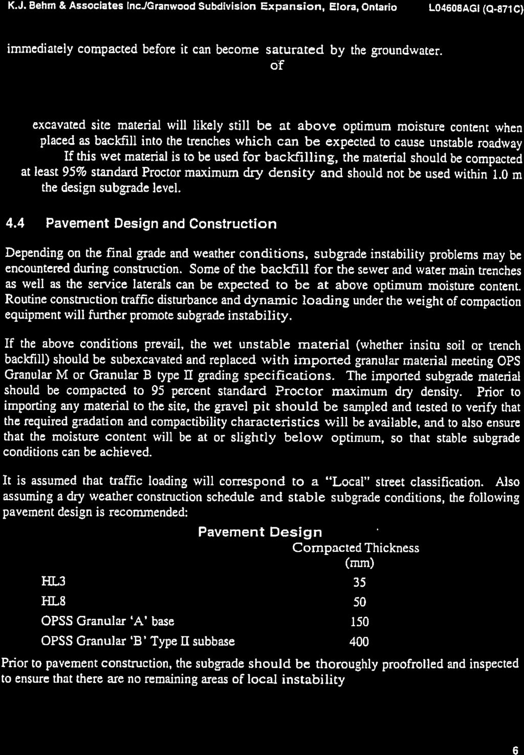
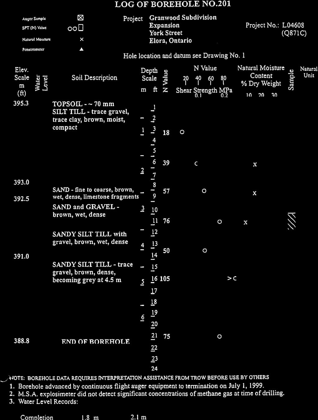
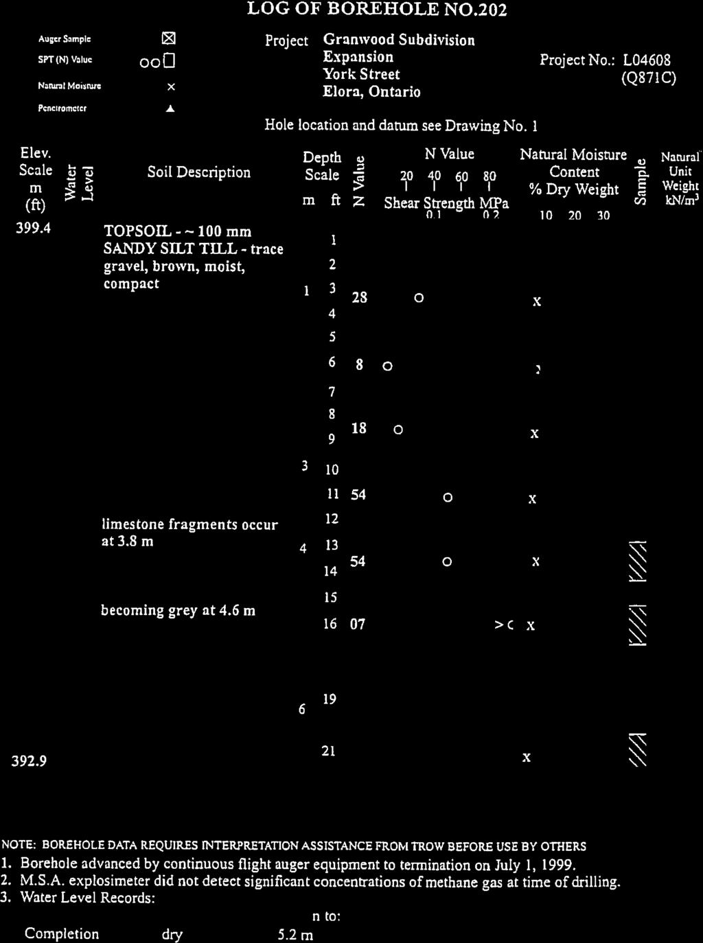
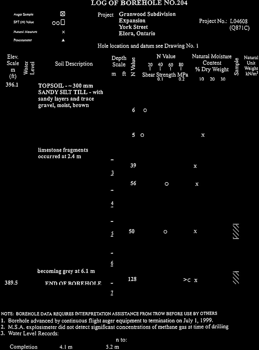
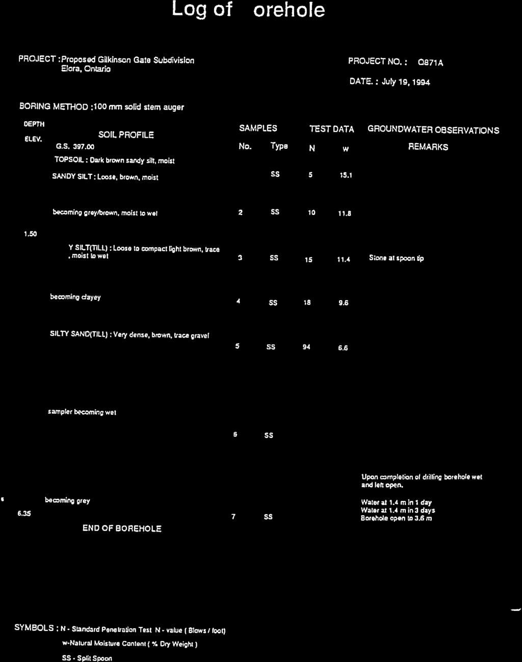
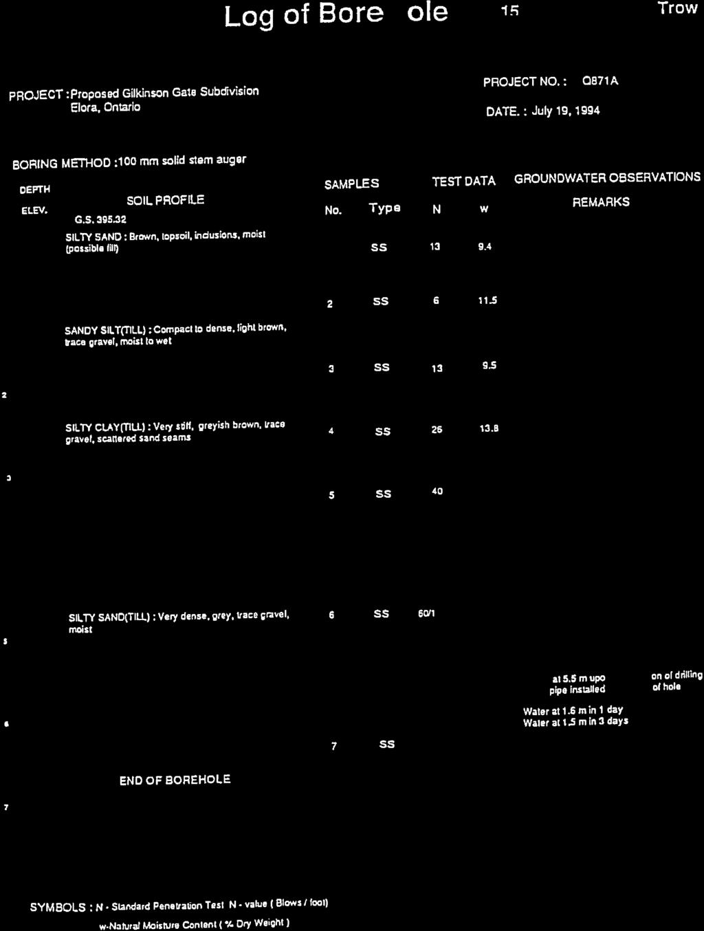
6 FUNCTIONAL SERVICING AND SWM REPORT EDGEHILL PROPERTIES LIMITED C/O WRIGHTHAVEN HOMES LTD. GRANWOOD GATE SUBDIVISION, PHASE III GMBP FILE NO REVISED FEBRUARY 2018 The Wellington County Soils Map (Ontario Soil Survey Report No. 35), prepared by the Department of Agriculture, describe soils at the site as smooth, gently sloping, Grey-Brown Podzolic, stone free loam till, with good drainage characteristics. A Preliminary Geotechnical Investigation was completed by Trow Consulting Engineers Ltd., revised August 27, 1999 for the site and is included as Appendix A. A total of four (4) test pits were completed on-site which found surficial topsoil which was underlain by fill which was underlain by sandy silt till. The Geotechnical Investigation estimates the groundwater on-site to be 1.8m to 4.1m below grade. The hydraulic conductivity of the underlying soils is estimated at 1x10⁻⁶ cm/sec. Under existing conditions the subject property generally slopes from the east to the west. 3. PROPOSED DEVELOPMENT The proposed development includes 54 single family residential lots, 12 semi-detached lots, 20 on-street townhouses, 66 stacked townhouses, walkway blocks, a stormwater management block and roadways throughout. A typical on-site roadway section is shown on Figure No Sanitary System The sanitary sewer system throughout the entire subdivision was originally designed by K.J. Behm & Associates Inc. in approximately Phase I and II have since been fully serviced and residents have been living within Phase I and II for several years. During the detailed design stage for Phase III, the sanitary sewer design will be peer reviewed in more; detail however at this time, it is anticipated that no capacity issues will exist with the current sanitary sewer system or downstream outlet sewers. A portion of the Phase III sanitary sewer was constructed during the development of Phase II along the proposed York street right-of-way in order to service the westerly portion of Phase II. The existing 200mm diameter sanitary sewer continues north along Waterloo Street to Nichol Street and then turns west on Nichol Street. Sanitary service connections to the proposed lots in Phase III were also constructed; however the lot fabric of the development has been revised since the time of construction. The existing service connections will therefore be relocated and/or abandoned as necessary to service the proposed Phase III lots and the existing sanitary sewer will be maintained. As part of Phase III, the sanitary sewer will be extended along Waterloo Street from York Street to the south for approximately 170 metres. This extension will serve as an outlet for the sanitary flows from Halls Drive within Phase III. Individual lateral service connections will be provided for each lot as per current municipal and provincial standards. 3.2 Storm System As per current practice and guidelines, the stormwater management approach for this development is a treatment train designed to remove sediment prior to discharge to the existing municipal storm sewer system. The treatment train will include lot level and end-of-pipe management practices. Lot level controls will consist of directing roof leaders to grassed surfaces to promote infiltration. End-ofpipe controls will be provided by a wetland type stormwater management (SWM) facility located along the west property limit of the Phase III development, adjacent to the Waterloo Street right-of-way. Oil/grit 2 OF 8
7 FILE:W:\Guelph\ \ Granwood SWM Review\5 Work In Progress\Drafting\ FIGURES.dwg LAYOUT:TYP. X-SEC LAST SAVED BY:Fcrew, 3/1/2018 1:28:00 PM PLOTTED BY:Field Crew - GM BluePlan 3/1/2018 3:56:43 PM TYPICAL CROSS SECTION FOR 8.0m ROAD ON 20.0m R.O.W. N.T.S. GRANWOOD GATE SUBDIVISION, PHASE 3 TOWNSHIP OF CENTRE WELLINGTON (ELORA) Not To Scale TYPICAL ROAD CROSS SECTION Figure No. 3 BluePlan ENGINEERING FEBRUARY 2018 Scale: N.T.S.
8 FUNCTIONAL SERVICING AND SWM REPORT EDGEHILL PROPERTIES LIMITED C/O WRIGHTHAVEN HOMES LTD. GRANWOOD GATE SUBDIVISION, PHASE III GMBP FILE NO REVISED FEBRUARY 2018 separators will also be utilized as part of the treatment train approach to stormwater quality control. These units will be placed within the storm sewer network prior to discharging to the stormwater management pond. The specific design of these oil/grit separators will be considered at the time of detailed design. Minor storm runoff from the development will discharge to the SWM facility via the proposed municipal storm sewer system. Major storm runoff exceeding the capacity of the storm sewer system will be conveyed overland via the municipal right-of-way to the SWM facility. There is currently no outlet for the proposed SWM facility. As part of the Phase III development, a storm sewer outlet is proposed from the outlet pipe of the SWM facility, along Waterloo Street, York Street West, and High Street north to McNab Street, for a distance of approximately 550 metres, where a connection is proposed to the existing 975mm diameter storm sewer that ultimately discharges to the Grand River. The existing 975mm storm sewer outlet to the Grand River was installed by the municipality in anticipation of the proposed Phase III development. The location of the proposed storm sewer is shown in Figure No. 4. Preliminary design of the proposed storm sewer outlet was prepared by the Township of Centre Wellington, and is provided in Appendix B. The design of the proposed storm sewer outlet will be finalized the time of detailed design. A portion of the Phase III development is proposed to outlet eastward to the existing Phase I & II SWM Pond. The Phase I & II pond was designed to accommodate this portion of the Phase III development. A portion of the Phase III development will drain uncontrolled off-site to the existing Trestle Bridge Trail ditch south of the site. The Phase III SWM facility will be designed with a sediment forebay to provide energy dissipation and promote sediment settlement. The facility will also be designed with an outlet structure to attenuate flows to the proposed storm sewer outlet. As per Township standards, storm services will be provided to each lot which will be provided on the Plans during the detailed design. Further details regarding the SWM facility are provided in Section 4.0 below. 3.3 Water System A 200mm diameter municipal watermain currently exists along Waterloo Street from approximately South Queen Street to Nichol Street and within the York Street East right-of-way through Phase III. A watermain also currently exists along Fisher Street and Halls Drive within the Phase II portion of the subdivision and is currently stubbed at the boundary of Phase III. A portion of the Phase III watermain was constructed during the development of Phase II along the proposed York street right-of-way. The existing 200mm diameter watermain continues north along Waterloo Street to Nichol Street and then turns west on Nichol Street. As part of the Phase III development, the existing watermain on Waterloo Street will be extended southerly for approximately 50 metres and will connect to Halls Drive with a 90 degree bend. The existing watermain on Halls Drive will be extended from the existing stub and connect to the proposed watermain extension on Waterloo Street. A watermain is also proposed on Carter Place which will tee off of the existing watermain located within the York Street East right-of-way within Phase III and be installed to the end of the cul-de-sac, terminating at a hydrant to provide flushing and maintenance capabilities. 3 OF 8
9 FILE:W:\Guelph\ \ Granwood SWM Review\5 Work In Progress\Drafting\ FIGURES.dwg LAYOUT:OUTLET FIG LAST SAVED BY:Fcrew, 3/1/2018 1:28:00 PM PLOTTED BY:Field Crew - GM BluePlan 3/1/2018 3:56:43 PM THIS DATA IS FOR ILLUSTRATIVE PURPOSES ONLY. INFORMATION CONTAINED HEREON IS NOT A SUBSTITUTE FOR PROFESSIONAL REVIEW OR A SITE SURVEY AND IS SUBJECT TO CHANGE WITHOUT NOTICE. WELLINGTON COUNTY, AND GM BLUEPLAN TAKE NO RESPONSIBILITY FOR, NOR GUARANTEES, THE ACCURACY OF THE INFORMATION CONTAINED ON THIS MAP. ANY INTERPRETATIONS OR CONCLUSIONS DRAWN FROM THIS MAP ARE THE SOLE RESPONSIBILITY OF THE USER PARK RD. WELLINGTON RD. 7 VICTORIA ST. McNAB ST. HIGH ST. WELLINGTON ST. NICHOL ST. WATERLOO ST. METCALF ST. McNAB ST. CARLTON PL. CLYDE ST. WATER ST. GRAND RIVER EAST YORK ST. W ELGIN ST. SUBJECT PROPERTY TRESTLE FISHE 30 GRANWOOD GATE SUBDIVISION, PHASE 3 TOWNSHIP OF CENTRE WELLINGTON (ELORA) N LEGEND EXISTING 975Ø STORM SEWER PROPOSED STORM SEWER :2000 (m) PROPOSED STM SEWER GRANWOOD SUBDIVISION POND OUTLET Figure No. 4 BluePlan ENGINEERING FEBUARY 2018 Scale: 1:2500 NAD 1983 UTM Zone 17N
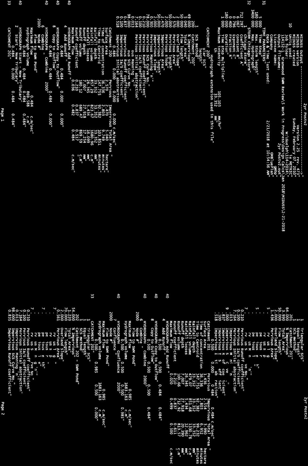
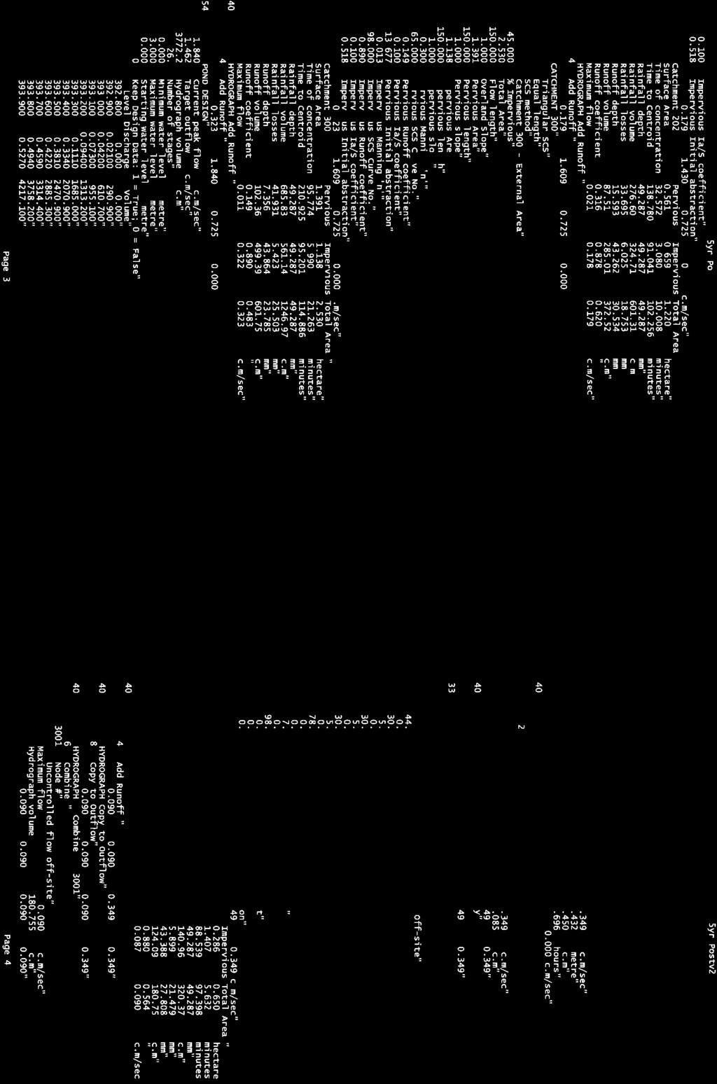
10 FUNCTIONAL SERVICING AND SWM REPORT EDGEHILL PROPERTIES LIMITED C/O WRIGHTHAVEN HOMES LTD. GRANWOOD GATE SUBDIVISION, PHASE III GMBP FILE NO REVISED FEBRUARY 2018 Individual lateral service connections will be provided for each lot as per current municipal and provincial standards. 4. STORMWATER MANAGEMENT 4.1 Design Criteria The stormwater management criteria used for the analysis of the site is as follows: 1. The 100-year allowable outlet rate to the proposed storm sewer outlet in the Waterloo Street right-of-way shall be the lesser of the 100-year pre-development peak flow rate and the design capacity of the outlet storm sewer. Preliminary design of the outlet storm sewer provided by the Township of Centre Wellington indicates that the design capacity of the outlet sewer is approximately 0.840m 3 /s. A copy of the Township s preliminary design is provided in Appendix B. 2. The post-development peak runoff rates to the proposed storm sewer outlet shall be less than the pre-development peak runoff rates to the Waterloo Street right-of-way. 3. The minimum acceptable water quality level of discharge from the site is 80% TSS removal. The Chicago Storm rainfall distributions were used to generate rainfall for the 2-, 5-, and 100-year design storms. Rainfall data was obtained from the Environment Canada Short Duration Rainfall IDF Data for the Fergus Shand Dam station. This data was converted to Chicago Storm parameters using the IDF Curve Fit tool in the MIDUSS modeling software. The Chicago Storm parameters are provided in Table No. 1 below. The MIDUSS Curve Fit modeling is provided in Appendix C. Table No. 1: Chicago Storm Parameters Coefficient 2-Year 5-Year 100-Year A B C R Duration (min) Total Depth (mm) The SCS Curve Number infiltration method was used in the MIDUSS model. The parameters summarized in the following Table No. 2 were used according to the MTO Drainage Management Manual for a Group BC Soil Classification (Design Chart 1.09). Table No. 2: MIDUSS SCS Curve Number Parameters Group B Group BC Group C Impervious Areas Long Grass Areas (Meadow) Lawns (Farmstead) Pre-Development Conditions For pre-development analysis purposes, the site and the external drainage area west of the right-of-way were modelled as four (4) drainage catchments. The pre-development drainage catchments are shown on Figure No. 5 and described below. The pre-development MIDUSS computer modeling is attached in Appendix D. 4 OF 8
11 FILE:W:\Guelph\ \ Granwood SWM Review\5 Work In Progress\Drafting\ GRADING.dwg LAYOUT:STM FIG PRE DEVL LAST SAVED BY:Fcrew, 3/2/2018 1:27:44 PM PLOTTED BY:Field Crew - GM BluePlan 3/2/2018 1:30:46 PM WATERLOO STREET McNAB STREET HALLS DRIVE CLARKE STREET LEGEND 102 CATCHMENT NUMBER 10.13ha. 90% % IMPERVIOUS AREA IN HECTARES CATCHMENT BOUNDARY SUBDIVISION BOUNDARY EXISTING MAJOR OVERLAND FLOW EXISTING CONTOURS :2000 (m) PRE-DEVELOPMENT DRAINAGE AREA PLAN Figure No. 5 BluePlan ENGINEERING FEBRUARY 2018 Scale: 1:2000 NAD 1983 UTM Zone 17N N GRANWOOD GATE SUBDIVISION, PHASE 3 TOWNSHIP OF CENTRE WELLINGTON (ELORA) STORMWATER MANAGEMENT
12 FUNCTIONAL SERVICING AND SWM REPORT EDGEHILL PROPERTIES LIMITED C/O WRIGHTHAVEN HOMES LTD. GRANWOOD GATE SUBDIVISION, PHASE III GMBP FILE NO REVISED FEBRUARY 2018 Catchment 100 (10.25 hectares) represents the existing on-site drainage area which currently drains overland to Waterloo Street. Catchment 100 is comprised of the vacant portion of the site and ground cover consists primarily of grass and shrubbery. Catchment 300 (2.53 hectares) represents the external drainage area west of Waterloo Street. Catchment 300 encompasses portions of the industrial and residential lands west of the site and drains to the Waterloo Street right-of-way. Catchment 400 (0.65 hectares) represents the portion of the site which currently drains to the existing Trestle Bridge Trail ditch south of the site. Catchment 400 is comprised of vacant land and ground cover is primarily grass and shrubbery. Catchment 401 (0.14 hectares) represents the portion of the site which drains to the existing SWM Pond that was constructed as part of Phase I & II of the Granwood development. Ground cover is primarily grass and shrubbery. Note that this catchment area was accounted for in the design of the Phase I & II SWM Pond. 4.3 Post-Development Conditions For post-development analysis purposes, the site was modelled as six (6) drainage catchments. The post-development drainage catchments are shown on Figure No. 6 and described below. The postdevelopment MIDUSS computer modeling is attached in Appendix E. Catchment 200 (5.04 hectares) represents the northerly portion of the Phase III development which includes the proposed park block. Stormwater runoff from Catchment 200 will be conveyed to the proposed stormwater management facility via the proposed storm sewer system and overland flow routes. Catchment 201 (3.99 hectares) consists of the southerly portion of the Phase III development. Stormwater runoff from Catchment 201 will be conveyed to the proposed stormwater management facility via the proposed storm sewer system and overland flow routes. Catchment 202 (1.22 hectares) consists of the proposed stormwater management facility and surrounding areas. Runoff from Catchment 202 will drain overland to the stormwater management facility. Catchment 300 (2.53 hectares) represents the external drainage area west of Waterloo Street. Catchment 300 will remain unchanged from the pre-development condition and is proposed to drain via the proposed storm sewer and overland to the proposed stormwater management facility. Catchment 500 (0.65 hectares) represents the rear yards of the proposed lots along the south side of Halls Drive. Runoff from Catchment 500 will continue to drain uncontrolled to the existing Trestle Bridge Trail ditch south of the site. Catchment 501 (0.14 hectares) represents a portion of Halls Drive. Catchment 501 will continue to drain to the existing Phase I & II SWM Pond. This catchment area was accounted for in the design of the Phase I & II SWM Pond. The on-site stormwater management facility is proposed to be a wetland which will provide quantity control for all storms up to, and including, the 100-year design storm. The stormwater management facility is expected to provide runoff quality control quality for all storms up to, and including, the 2-year design storm. 5 OF 8
13 FILE:W:\Guelph\ \ Granwood SWM Review\5 Work In Progress\Drafting\ GRADING.dwg LAYOUT:STM FIG POST DEVL LAST SAVED BY:Fcrew, 3/2/2018 1:27:44 PM PLOTTED BY:Field Crew - GM BluePlan 3/2/2018 1:30:44 PM WATERLOO STREET PART 1, PLAN McNAB STREET PARK 61R HALLS DRIVE CLARKE STREET LEGEND 102 CATCHMENT NUMBER 10.13ha. 90% % IMPERVIOUS AREA IN HECTARES CATCHMENT BOUNDARY SUBDIVISION BOUNDARY PROPOSED MAJOR OVERLAND FLOW EXISTING MAJOR OVERLAND FLOW EXISTING CONTOURS :2000 (m) POST-DEVELOPMENT DRAINAGE AREA PLAN Figure No. 6 BluePlan ENGINEERING FEBRUARY 2018 Scale: 1:2000 NAD 1983 UTM Zone 17N N GRANWOOD GATE SUBDIVISION, PHASE 3 TOWNSHIP OF CENTRE WELLINGTON (ELORA) STORMWATER MANAGEMENT
14 FUNCTIONAL SERVICING AND SWM REPORT EDGEHILL PROPERTIES LIMITED C/O WRIGHTHAVEN HOMES LTD. GRANWOOD GATE SUBDIVISION, PHASE III GMBP FILE NO REVISED FEBRUARY 2018 The wetland was designed to meet the Ministry of the Environment (MOE) Stormwater Management Planning and Design Manual design guidelines. 4.3 Routing The hydrologic model MIDUSS was used to create the runoff hydrographs and to route the flows through the storage structure. The routing results for the proposed on-site stormwater management facility are summarized in Table No. 3 below. The output hydrographs are provided in Appendix E. Table No. 3: Proposed Stormwater Management Facility - Stage-Storage-Discharge Capacity Storage and Control Bottom of Active Storage/ Orifice Peak Flow m³/s Available Capacity Storage Volume m³ Storage Elevation m Peak Flow m³/s Actual Capacity Used Storage Volume m³ Storage Elevation m Year Year Year , Weir , Top of Pond , A summary of the pre- and post-development peak flow rates to the Waterloo Street stormwater outlet for the 2-, 5- and 100-year design storm events are provided in Table No. 4 below. Table No. 4: Summary of Peak Flow Rates to Waterloo Street Outlet (m 3 /s) 2 Year 5 Year 100 Year Pre- Development Peak Flow Rate (m 3 /s) Preliminary Design Capacity of Outlet Storm Sewer (m 3 /s) Post-Development Un-attenuated Peak Flow Rate (m 3 /s) Post- Development Controlled Peak Flow Rate from SWM Facility (m 3 /s) As shown in the above Table No. 4, the post-development peak flow rates to the Waterloo Street outlet are less than the pre-development peak flow rates for the 2-, 5- and 100-year design storm events. The 100-year post-development peak flow rate is also less than the preliminary design capacity of the outlet storm sewer (0.840m 3 /s). A summary of the pre- and post-development peak flow rates to the existing Trestle Bridge Trail ditch south of the site and Phase I & II SWM Pond outlets for the 2-, 5- and 100-year design storm events are provided in Table No. 5 below. 6 OF 8
 Peak Flow Rates to Existing Trestle Bridge Trail Ditch Peak Flow Rates to Existing")
15 FUNCTIONAL SERVICING AND SWM REPORT EDGEHILL PROPERTIES LIMITED C/O WRIGHTHAVEN HOMES LTD. GRANWOOD GATE SUBDIVISION, PHASE III GMBP FILE NO REVISED FEBRUARY 2018 Table No. 5: Summary of Peak Flow Rates to the Ditch South of the Site and to the Existing Phase I & II SWM Pond (m 3 /s) Peak Flow Rates to Existing Trestle Bridge Trail Ditch Peak Flow Rates to Existing Phase I & II SWM Pond 2-Year 5-Year 100-Year 2-Year 5-Year 100-Year Pre- Development Peak Flow Rate (m 3 /s) Post-Development Unattenuated Peak Flow Rate (m 3 /s) As shown in Table No. 5, the increase in peak flow rates to the existing Trestle Bridge Trail ditch south of the site are minor (0.104m 3 /s during the 100-year storm event) and does not require quantity control measures, as runoff to the ditch will be exclusively from grassed areas and rooftop, and is therefore considered clean. As discussed above, the existing Phase I & II SWM was designed to accommodate runoff from Catchment 501, therefore no additional SWM control measures are required for this catchment. 5. WATER QUALITY Initial water quality treatment on individual lots will begin with roof leader runoff discharging to the surface and allowing the grass cover to provide initial quality treatment. Oil/grit separators will also be utilized as part of the treatment train approach to stormwater quality control. These units will be placed within the storm sewer network prior to discharging to the stormwater management pond. The specific design of these oil/grit separators will be considered at the time of detailed design. Final water quality will be achieved through the proposed on-site stormwater management facility (wetland). The 2-year design storm event was used to size the quality control component of the stormwater management facility. As shown in the wetland sizing details provided in Appendix F, the wetland is capable of removing 80% of the TSS. 6. ROADWAYS AND GRADING All proposed roadways are to be developed to full urban standards, with storm sewers, sanitary sewers, watermain, curb and gutter, and street lighting. Sidewalks are proposed on one side of Halls Drive, and both sides of York Street. No sidewalks are proposed for Carter Place. Due to the natural easy slope of the lands from east to west, appropriate road grades can be achieved to provide positive drainage towards the SWM facility. Proposed road grades will typically be within the range of 0.5% to 2.0%. Typical proposed lot grades will be within the range of 2.0% to 5.0% in accordance with Township standards. 7 OF 8

16
17 Appendix A Preliminary Geotechnical Investigation
18

19
20

21

22

23

24

25
26


27

28
29
30
31
32
33
34
35
36
37
38

39
40

41
42

43
44
45
46

47
48 Appendix B Township of Centre Wellington Preliminary Outlet Storm Sewer Design


49 M6430A


50 FOR REFERENCE M6430A
51
52 Appendix C MIDUSS IDF Curve Fit Modeling
53 Rainfall Distribution Calc " MIDUSS Output >" " MIDUSS version Version 2.25 rev. 473" " MIDUSS created Sunday, February 07, 2010" " 10 Units used: ie METRIC" " Job folder: W:\Guelph\ \" " Granwood SWM Review\5 Work in Progress\Design Calcs\Modeling Files" " 85 IDF CURVE FIT" " 6 Number of Storms" " 1 Storm no." " 2 Return interval" " 12 Data Pairs" " " " " " minutes" " " " " " mm" " " " " " mm/hr" " mm/hr 'A' coeff." " minutes 'B' coeff." " 'C' exponent" " Std.error of estimate" " 2 Storm no." " 5 Return interval" " 12 Data Pairs" " " " " " minutes" " " " " " mm" " " " " " mm/hr" " mm/hr 'A' coeff." " minutes 'B' coeff." " 'C' exponent" " Std.error of estimate" " 3 Storm no." " 10 Return interval" " 12 Data Pairs" " " " " " minutes" " " " " " mm" " " " " " mm/hr" " mm/hr 'A' coeff." " minutes 'B' coeff." " 'C' exponent" " Std.error of estimate" " 4 Storm no." " 25 Return interval" " 12 Data Pairs" " " " " " minutes" Page 1
54 Rainfall Distribution Calc " " " " " mm" " " " " " mm/hr" " mm/hr 'A' coeff." " minutes 'B' coeff." " 'C' exponent" " Std.error of estimate" " 5 Storm no." " 50 Return interval" " 12 Data Pairs" " " " " " minutes" " " " " " mm" " " " " " mm/hr" " mm/hr 'A' coeff." " minutes 'B' coeff." " 'C' exponent" " Std.error of estimate" " 6 Storm no." " 100 Return interval" " 12 Data Pairs" " " " " " minutes" " " " " " mm" " " " " " mm/hr" " mm/hr 'A' coeff." " minutes 'B' coeff." " 'C' exponent" " Std.error of estimate" " 38 START/RE-START TOTALS " " 3 Runoff Totals on EXIT" " Total Catchment area hectare" " Total Impervious area hectare" " Total % impervious 0.000" " 19 EXIT" Page 2
55 Appendix D Pre-Development MIDUSS Computer Model Output for the 2-, 5- and 100-Year Design Storms
56
57

58
59
60

61
62 Appendix E Post-Development MIDUSS Computer Model Output for the 2-, 5- and 100-Year Design Storms and Stage-Storage Discharge Calculation Tables
63 Granwood Subdivision Township of Centre Wellington GMBP File: Stormwater Management Pond Storage Volume Calculations Surface Perm. Pool Accum. P.P. Surface Active Accum. Active Elevation Depth Area Volume Volume Area Volume Volume (m) (m) (m 2 ) (m 3 ) (m 3 ) (m 2 ) (m 3 ) (m 3 ) Bottom of Pond Permanent Pool/Top of Forebay , , , , , Catchbasin Inlet Lip , , , , , , , , , , , , , , , , , , Weir , Top of Pond Orifice (Quality) Orifice (Quantity) Overflow Weir ( m) ( m) ( m) Q = m 3 /s Q = m 3 /s d1 = 2.50 m Cd = Cd = h = 2.30 m H = m H = m H = 0.20 m 2g = g = g = L = 7.00 m A = m 2 A = m 2 D = m D = m Q = 0.87 m 3 /s
64 Stormwater Management Pond Stage-Storage-Discharge Table Elevation Stage Storage 300 mm Orifice Catchbasin Inlet Lip Overflow Weir Total Discharge m m m (m) (m) (m 3 ) (m 3 /s) (m 3 /s) (m 3 /s) (m 3 /s) Permanent Pool/Top of Forebay , , Catchbasin Inlet Lip , , , , , , , , , , , , , , , , , , Weir , , Top of Pond
65

66
67

68
69
70
71

72
73
74
75
76
77 Appendix F Wetland Facility Sizing Details
78 Project No Project: Granwood Gate Subdivision, Phase III Date: February 22, 2018 Designer: Peter Soligo Stormwater Management Facility Quality Sizing: The stormwater management facility has been designed to function as a wetland. From Table 3.2 of the MOE Stormwater Management Planning and Design Manual, 2003, in order to provide Enhanced water quality treatment (80% TSS Removal), a wetland facility requires: 105m³/ha of quality storage volume for a contributing drainage area that is approximately 55% impervious. 40m³/ha of the required quality storage volume is extended detention volume, while the remaining is permanent pool. Calculating the total required quality volume: Total contributing drainage area = 12.82ha Combined imperviousness of contributing area = 53% (assume 55% for quality sizing purposes) Quality Storage Requirement = 105m 3 /ha = 1,346m 3 Calculating Extended Detention Volume: Extended Detention Requirement = 40m 3 /ha for site and external areas Required Extended Detention Volume = 513m 3 Calculating Permanent Pool Volume: Required Permanent Pool Volume = Total Quality Volume Extended Detention Volume Required Permanent Pool Volume = 833m 3 Alternative Extended Detention Sizing: Given that the 2 year storm has been used as the quality sizing event for this facility, the extended detention volume is required to store at a minimum the full capacity of the 2-year design storm. From the MIDUSS modeling, the 2-year design storm requires a maximum storage volume of approximately m 3, which correspond to an elevation of m. As such, the inlet of the catchbasin outlet structure has been set at an elevation of m. A summary of the quality sizing volumes are provided in Table No. E-1 below:
79 Table No. E-1: Quality Sizing Volumes Summary Required Provided Extended Detention Volume m m 3 Permanent Pool Volume 833m 3 1,158.6m 3 Total Quality Volume 1,346m m 3 Sediment Forebay Design The Sediment forebay has been designed to meet the MOE Stormwater Management Planning and Design Manual requirements for wetland facilities. The design of the forebay is summarized in Table No. E-2 below: Table No. E-2: Forebay Design Details Forebay Settling Length (m) 13.8 Dispersion Length (m) 29.0 Required Flow Velocity (m/s) 0.15 Length to Width Ratio 2:1 Settling Velocity (m/s) Forebay Length (m) 56 Provided Flow Velocity (m/s) 0.05 Length to Width Ratio 2:1
Appendix K. Stormwater Management Plan
 Regional Municipality of Halton - Steeles Avenue (Regional Road 8) Class EA - Industrial Drive to Regional Road 25/Martin Street Appendix K Stormwater Management Plan PR226401.001 Rev. 2 PR.DOT, 00/01
CHECKLIST FOR PHASE II DRAINAGE REPORT
 I. COVER SHEET CHECKLIST FOR PHASE II DRAINAGE REPORT A. Name of Project B. Address C. Owner D. Developer E. Engineer F. Submittal date and revision dates as applicable II. GENERAL LOCATION AND DESCRIPTION
GLOBAL CENTRE FOR PLURALISM 330 Sussex Drive Ottawa, Ontario SITE SERVICING & STORMWATER MANAGEMENT OVERVIEW UPDATE REPORT.
 GLOBAL CENTRE FOR PLURALISM 330 Sussex Drive Ottawa, Ontario SITE SERVICING & STORMWATER MANAGEMENT OVERVIEW UPDATE REPORT Submitted to: Kuwabara Payne McKenna Blumberg Architects 322 King Street West,
Keele Campus Storm Drainage. Presented by Mark Hagesteijn September 24, 2013
 Keele Campus Storm Drainage Presented by Mark Hagesteijn September 24, 2013 1 Presentation Overview Urbanization Impact on the Hydrologic Cycle Why Do We Manage Stormwater? Typical Stormwater Management
October 7, City of Thornton 9500 Civic Center Drive Thornton, CO (303) RE: Maverik Thornton, CO - Drainage Report
 RE: Maverik Thornton, CO - Drainage Report") October 7, 2016 City of Thornton 9500 Civic Center Drive Thornton, CO 80229 (303) 538-7295 RE: Maverik Thornton, CO - Drainage Report As per your request, we are submitting to you the drainage report and
October 7, 2016 City of Thornton 9500 Civic Center Drive Thornton, CO 80229 (303) 538-7295 RE: Maverik Thornton, CO - Drainage Report As per your request, we are submitting to you the drainage report and
MASTER DEVELOPMENT DRAINAGE PLAN FOR MONUMENT HEIGHTS
 MASTER DEVELOPMENT DRAINAGE PLAN FOR MONUMENT HEIGHTS DRAINAGE REPORT STATEMENT ENGINEER'S STATEMENT: The attached drainage plan and report were prepared under my direction and supervision and are correct
C ity of Grande Prairie Development Services Department
 C ity of Grande Prairie Development Services Department FAIRWAY DEVELOPMENT OUTLINE PLAN OP 08 09 Approved April 6, 2009 Prepared by: Focus Corporation Table of Contents 1.0. Introduction 2 3 1.1. Plan
City of Richmond. Engineering Design Specifications
 City of Richmond Design Specifications June 2008 CITY OF RICHMOND ENGINEERING DESIGN SPECIFICATIONS JUNE 2008 THIS DOCUMENT DETAILS THE MINIMUM STANDARDS TO BE USED FOR THE DESIGN OF ENGINEERING PROJECTS
Pollutant Removal Benefits
 Bioswales Bioswales Similar to biocells, but have a slight, but positive grade toward an outlet Designed to convey the WQv event at very low velocities Promote filtration through native vegetation, infiltration
LEGACY RIDGE STAGE 2 OUTLINE PLAN BRIEF
 TABLE OF CONTENTS 1.0 INTRODUCTION... 1 2.0 LOCATION... 2 3.0 LAND OWNERSHIP... 7 4.0 PLANNING CONTEXT... 9 5.0 PROPOSED LAND USES...10 6.0 LANDSCAPING...11 7.0 ARCHITECTURAL CONTROLS...13 8.0 PROPOSED
Leduc Industrial Outline Plan SE W4
 Leduc Industrial Outline Plan SE 1-50-25-W4 Within the North Leduc Industrial ASP Prepared for: Leduc Energy Park Ltd. Prepared by: Stantec Consulting Ltd. File No. 1161 104655 V5 Table of Contents 1.0
CITY OF CAMBRIDGE STORMWATER MANAGEMENT. POLICIES and GUIDELINES
 CITY OF CAMBRIDGE STORMWATER MANAGEMENT POLICIES and GUIDELINES August 2011 Stormwater Management Policies and Guidelines August 2011 TABLE OF CONTENTS Stormwater Management Policies and Guidelines August
Chapter 4 - Preparation of Stormwater Site Plans
 Chapter 4 - Preparation of Stormwater Site Plans The Stormwater Site Plan is the comprehensive report containing all of the technical information and analysis necessary for the City to evaluate a proposed
Draft Rhode Island Stormwater Design and Installation Standards Manual
 Draft Rhode Island Stormwater Design and Installation Standards Manual Summary The May 2009 Public Review Draft version of the RI Stormwater Design and Installation Standards Manual consists of approximately
Moon Brook FRP BMP Summary Sheet. Ownership of Land where BMP is Located
 Outlet Retrofit Hitzel Terrace The town owned parcel along Hitzel Terrace is a natural wetland area which currently provides some level of stormwater detention and peak-flow attenuation. The proposed project
PRELIMINARY DRAINAGE REPORT LATHAM 200 MMSCFD GAS PROCESSING PLANT
 PRELIMINARY DRAINAGE REPORT LATHAM 200 MMSCFD GAS PROCESSING PLANT LOTS B, RECORDED EXEMPTION 1211-2-1, RECX13-0096 LOCATED IN THE NORTH 1/2 OF SECTION 2, TOWNSHIP 3 NORTH, RANGE 66 WEST, 6 TH PRINCIPAL
6.1. INTRODUCTION AND SUMMARY OF FINDINGS
 Chapter 6: Stormwater Management 6.1. INTRODUCTION AND SUMMARY OF FINDINGS A Stormwater Pollution Prevention Plan (SWPPP) has been prepared for the Proposed Project in accordance with the requirements
Appendix B.1. Storm Servicing and Stormwater Management Memorandum
 Appendix B.1 Storm Servicing and Stormwater Management AECOM 410 York Street, Citi Plaza 519 673 0510 tel London, ON, Canada N6A 6K2 519 673 5975 fax www.aecom.com DRAFT To Doug Law (City of London) Page
PCE PRELIMINARY DRAINAGE ANALYSIS REPORT FOR WESTWOOD MIXED USE NEIGHBORHOOD PROJECT 772 NORTH FOREST ROAD TOWN OF AMHERST, ERIE COUNTY, NEW YORK
 PCE PRELIMINARY DRAINAGE ANALYSIS REPORT FOR WESTWOOD MIXED USE NEIGHBORHOOD PROJECT 772 NORTH FOREST ROAD TOWN OF AMHERST, ERIE COUNTY, NEW YORK MAY 19, 2014 Prepared By: Timothy M. Lavocat, P.E., CFM
STAFFORD TRACT NORTH OF US90A 1.0 INTRODUCTION 1.1 OBJECTIVE
 1.0 INTRODUCTION 1.1 OBJECTIVE This report, prepared for submittal to TxDOT, analyzes existing and proposed detention facilities draining into the TxDOT US90A storm sewer system. The results of the detailed
BRISBANE BAYLANDS INFRASTRUCTURE PLAN FEBRUARY 2011 APPENDIX O DRAFT
 BRISBANE BAYLANDS INFRASTRUCTURE PLAN FEBRUARY 2011 APPENDIX O DRAFT PRELIMINARY STORM DRAIN CALCULATIONS ASSOCIATED WITH BRISBANE BAYLANDS REDEVELOPMENT BRISBANE, CALIFORNIA Prepared by BKF Engineers
MANUAL OF DESIGN, INSTALLATION, AND MAINTENANCE REQUIREMENTS FOR STORMWATER MANAGEMENT PLANS
 MANUAL OF DESIGN, INSTALLATION, AND MAINTENANCE REQUIREMENTS FOR STORMWATER MANAGEMENT PLANS May 2007 SECTION 1 Responsibility of Applicant TABLE OF CONTENTS A. Stormwater Management Plan Required Information
Palisades Outline Plan
 NE ¼ 25 36 28 W4 Town of Penhold Approved August 13, 2012 Contents Figures & Tables... 2 Introduction... 1 Overview... 1 Purpose... 1 Development Area... 3 Ownership... 3 Topography... 3 Existing & Surrounding
Development of LID Design Guide in Edmonton
 Development of LID Design Guide in Edmonton Xiangfei Li and Fayi Zhou, the City of Edmonton Dan Healy, AMEC Earth and Environmental Philadelphia LID Symposium September 26, 2011 Outline Why LID Why develop
Severn River Sub-Watershed: BMP 09-Retrofit
 Project ID: BMP_09 Total Treated Drainage Area: 4.57 acres Total Treated Impervious Area: 2.9 acres Total Water Quality Volume (WQv): ~10,300 cubic feet; 0.236 acre-foot Rainfall Depth Treated (Pe): 1
Figure 1 Cypress Street Study Area Location Map
 July 20, 2016 TO: FROM: Jim Massarelli Director of Engineering Jeff Julkowski, PE Michael Burke, PE SUBJECT: Cypress Street Study Area Stormwater Analysis (CBBEL Project No. 16-0058) At the request of
DFH JOINT VENTURE. Stormwater Management Report for Proposed Residential Subdivision at Graham Block, Pokeno
 DFH JOINT VENTURE Stormwater Management Report for Proposed Residential Subdivision at Graham Block, Pokeno DOCUMENT CONTROL RECORD Document: DFH Joint Venture Graham Block Stormwater Management Report
Appendix I. Checklists
 Appendix I Checklists Town of Greenwich Drainage Manual Department of Public Works - Engineering Division Town Hall - 101 Field Point Road, Greenwich, CT 06836-2540 Phone 203-622-7767 - Fax 203-622-7747
When planning stormwater management facilities, the following principles shall be applied where possible.
 2.0 Principles When planning stormwater management facilities, the following principles shall be applied where possible. 2.0.1 Drainage is a regional phenomenon that does not respect the boundaries between
WQ-23 MOUNTAINOUS AND STEEP SLOPE SITES
 Greenville County Technical Specification for: WQ-23 MOUNTAINOUS AND STEEP SLOPE SITES 1.0 Mountainous and Steep Slope Sites 1.1 Description The geographic locations of portions of Greenville County are
26 Attachment 2. Township of New Britain APPENDIX B STORMWATER MANAGEMENT DESIGN CRITERIA
 (26, APPENDIX B) 26 Attachment 2 Township of New Britain APPENDIX B STORMWATER MANAGEMENT DESIGN CRITERIA TABLE B-1 DESIGN STORM RAINFALL AMOUNT Source: Field Manual of Pennsylvania Department of Transportation
Bylaw C-1186 Adopted November 5, Planning and Development Services
 Bylaw C-1186 Adopted November 5, 2007 Planning and Development Services CITY OF GRANDE PRAIRIE OFFICE CONSOLIDATION BYLAW C-1186 A Bylaw to adopt the Westgate Area Structure Plan (As Amended by Bylaw C-1186-1,
6.1. INTRODUCTION 6.2. EXISTING CONDITIONS
 Chapter 6: Stormwater Management 6.1. INTRODUCTION This Chapter describes the current drainage patterns on the Project Site, the stormwater management system that is proposed as part of the Proposed Project,
Planning Justification Report
 Planning Justification Report Application for Draft Plan of Subdivision, Official Plan Amendment and Zoning Bylaw Amendment for Lift of Hold Proposed Residential Development Part of Lots 34 & 35, Concession
PHASE III DRAINAGE REPORT
 PHASE III DRAINAGE REPORT FOR Eastlake Assisted Living & Memory Care April 20, 2016 June 3, 2016 August 5, 2016 Prepared for: 3301 E 120 th Ave, LLC. 8200 E. Maplewood Ave., Suite 150 Greenwood Village
Table 4.7.1: Swales Potential Application and Storm Water Regulation
 4.7. Swales A swale is a vegetated open channel, planted with a combination of grasses and other herbaceous plants, shrubs, or trees. A traditional swale reduces peak flow at the discharge point by increasing
PLANNED UNIT DEVELOPMENT & SUBDIVISION STAFF REPORT Date: May 18, 2017
 & PUD-0000102-2017 PLANNED UNIT DEVELOPMENT & SUBDIVISION STAFF REPORT Date: May 18, 2017 NAME SUBDIVISION NAME Dauphin Creek Estates Subdivision Dauphin Creek Estates Subdivision LOCATION CITY COUNCIL
PLANNING JUSTIFICATION REPORT
 PLANNING JUSTIFICATION REPORT 556, 560 and 576 Conservation Drive 2115881 Ontario Limited City of Waterloo, Regional Municipality of Waterloo Zoning By-law Amendment Draft Plan of Subdivision July 2016
APPENDIX F: DETAIL DRAWINGS
 APPENDIX F: DETAIL DRAWINGS DRAWING DIVISION 100 GENERAL NOTES 200 ROAD WAYS 300 TRAFFIC CONTROL 400 FENCES 500 SEDIMENT CONTROL 600 SANITARY AND STORM SEWERS 700 WATERMAIN 800 PARKS AND LANDSCAPING 900
HEALTH SCIENCES BUILDING REDEVELOPMENT PROJECT
 INTRODUCTION In recent years, the University of Cincinnati (University) has demonstrated a commitment to identifying and implementing sustainable goals and objectives throughout University s Uptown Campuses.
APPENDIX C: STORMWATER CONTROL PLAN
 APPENDIX C: STORMWATER CONTROL PLAN STORM WATER MANAGEMENT PLAN FOR PLEASANT HILL, CALIFORNIA Prepared for Compliance with the Clean Water Program (C.3) and the San Francisco Bay Regional Water Quality
Checklists. Project Name: Location: File Number: Date of Submittal: Reviewer: Date: Applicant: Contact Name: Phone Number:
 Applicant: Contact Name: Phone Number: Email: Project Name: Location: File Number: Date of Submittal: Reviewer: Date: Concept Plan Requirements: I. General Project Information 1. Address or parcel number
NAPA COUNTY PUBLIC WORKS Standards & Specifications
 Roadway Design & Construction Manual (Table of Contents) 1. Chapter 1: General Provisions 1.1 Short Title 1.2 Jurisdiction 1.3 Purpose and Effect 1.4 Enactment Authority 1.5 Amendment and Revisions 1.6
Holmberg & Howe, Land Surveyors and Civil Engineers Zoning District: R-35
 Development Impact Statement Name of Project: Red Tail Drive Acreage: 13.5 Acres± Type of Project: Residential Subdivision Owner: 96 East Street Development, LLC Location: rear of 112 East Street Parcel
Preliminary Sediment & Stormwater Management Plan Review Checklist DATE RECEIVED: PROJECT NUMBER: PROJECT NAME:
 Preliminary Sediment & Stormwater Management Plan Review Checklist DATE RECEIVED: PROJECT NUMBER: PROJECT NAME: General Information: 1. Completed application signed by the owner, review fee, one set of
STORMWATER REPORT FOR WALMART SUPERCENTER STORE # SIOUX FALLS, LINCOLN COUNTY, SOUTH DAKOTA BFA PROJECT NO
 STORMWATER REPORT FOR WALMART SUPERCENTER STORE # 2443-00 SIOUX FALLS, LINCOLN COUNTY, SOUTH DAKOTA BFA PROJECT NO. 3286 March 1, 2012 I hereby certify that this engineering document was prepared by me
New Development Stormwater Guidelines
 New Development Stormwater Guidelines CITY OF MOUNTLAKE TERRACE Table of Contents Introduction... 2 Ecology s Minimum Requirements for stormwater management... 2 Description of the 9 Minimum Requirements...
HUNTSVILLE PHYSICAL SERVICES DEPARTMENT
 HUNTSVILLE PHYSICAL SERVICES DEPARTMENT URBAN DEVELOPMENT SITE PLAN CONTROL DRAWING DESIGN GUIDE April, 2000 (Revised June, 2003) TABLE OF CONTENTS Part A. General Information Page 1 Part B. Site Servicing
Placement of the soil should be in lifts of mm and loosely compacted (tamped lightly with a backhoe bucket).
.") 6 Rain Gardens Rain Gardens 6.1 Introduction A rain garden is used to attenuate peak flows and to provide stormwater treatment. Rain gardens use the concept of bioretention, a water quality practice in
6 Rain Gardens Rain Gardens 6.1 Introduction A rain garden is used to attenuate peak flows and to provide stormwater treatment. Rain gardens use the concept of bioretention, a water quality practice in
 PSLS Surveyors' Conference Workshop Information Form Workshop Number: (leave blank if unknown) Hours: Workshop Title: Workshop Description: Suggested Speaker(s), affiliation/contact information 1. 2. 3.
R1a: REINFORCED TURF TO REPLACE GRAVEL /GRASS PARKING ADJACENT TO SOUTH PENNSYLVANIA AVENUE.
 R1a: REINFORCED TURF TO REPLACE GRAVEL /GRASS PARKING ADJACENT TO SOUTH PENNSYLVANIA AVENUE. Description The retrofit site is located along South Pennsylvania Avenue, between Maplewood Street and just
STORMWATER MANAGEMENT CODES ANALYSIS RICHLAND COUNTY, SC SITE PLANNING ROUNDTABLE
 STORMWATER MANAGEMENT CODES ANALYSIS RICHLAND COUNTY, SC SITE PLANNING ROUNDTABLE Codes analyses for each subcommittee were completed to assist participants of the Richland County Site Planning Roundtable.
PRELIMINARY STAFF PLANNING REPORT TO THE WALWORTH COUNTY ZONING AGENCY X CONDITIONAL USE
 This report was prepared prior to the public hearing. This report may be supplemented or amended to reflect the review of additional information presented at the public hearing and written material submitted
ENBRIDGE GAS DISTRIBUTION INC. Proposed Relocation for Ninth Line, Markham and Whitchurch-Stouffville. Environmental Screening Report
 Page 1 of 18 ENBRIDGE GAS DISTRIBUTION INC. Proposed Relocation for Ninth Line, Markham and Whitchurch-Stouffville Environmental Screening Report July 2011 Page 2 of 18 Table of Contents 1.0 INTRODUCTION
APPENDIX A SIMPLIFIED APPROACH TO STORMWATER MANAGEMENT FOR SMALL PROJECTS. In West Sadsbury Township, Chester County, Pennsylvania
 APPENDIX A SIMPLIFIED APPROACH TO STORMWATER MANAGEMENT FOR SMALL PROJECTS In West Sadsbury Township, Chester County, Pennsylvania TABLE OF CONTENTS I. Introduction 3 II. Importance of Stormwater Management
168 & 170 BRADFORD STREET
 168 & 170 BRADFORD STREET City of Barrie prepared by: C.C. Tatham & Associates Ltd. 41 King Street, Unit 4 Barrie, Ontario L4N 6B5 Tel: (705) 733-9037 Fax: (705) 733-1520 info@cctatham.com prepared for:
SITE PLAN REVIEW APPLICATION AND CHECKLIST
 SITE PLAN REVIEW APPLICATION AND CHECKLIST PROJECT SUMMARY: Project Name: City/ETA Location: City ETA (Application fee & number of copies needed are based on location) Property Location (Legal Description
ENGINEERING & CONSTRUCTION MANAGEMENT
 DATE: PROJECT: DIVISION OF ENGINEERING & CONSTRUCTION MANAGEMENT PLAN REVIEW PERMITTING ENGINEERING CONSTRUCTION COUNTY PLAN FILE NUMBERS: DESIGN FIRM: PRELIMINARY SUBDIVISION PLAT CHECKLIST INSTRUCTIONS:
Letter of Credit Itemized Cost Estimate For: 100% Site Development Costs
 Letter of Credit Itemized Cost Estimate For: 100% Site Development Costs The following form is to be filled out by the Project Consultant(s) and submitted to the City of Kitchener, Planning Division for
Low Impact Development (LID) Techniques. Associate BD Presentation, October 7, 2014
 Techniques. Associate BD Presentation, October 7, 2014") Low Impact Development (LID) Techniques Associate BD Presentation, October 7, 2014 Low Impact Development (LID) Techniques What are LIDs? Why are they used? Where are they used? How are they designed or
Low Impact Development (LID) Techniques Associate BD Presentation, October 7, 2014 Low Impact Development (LID) Techniques What are LIDs? Why are they used? Where are they used? How are they designed or
Three Rivers Park District Administration Center Rain Garden
 Three Rivers Park District Administration Center Rain Garden Introduction There are significant changes to the hydrologic regime and nutrient loading following urban and industrial development. The post-development
SMALL PROJECTS SIMPLIFIED APPROACH
 SMALL PROJECT APPLICATION AND STORMWATER MANAGEMENT DESIGN ASSISTANCE MANUAL FOR SMALL PROJECTS IN FULTON TOWNSHIP LANCASTER COUNTY, PENNSYLVANIA SMALL PROJECTS SIMPLIFIED APPROACH Prepared By: Light-Heigel
4. CONCEPT PLAN DEVELOPMENT
 4. CONCEPT PLAN DEVELOPMENT Concept Plan Step 1: Identify Site Constraints and Opportunities Review the existing site to identify constraints and opportunities for GI Practices to meet the RRv. Constraints
A. INTRODUCTION AND SUMMARY OF FINDINGS B. EXISTING CONDITIONS. Table 10-1 Adjacent Storm Drains
 Chapter 10: Stormwater Management A. INTRODUCTION AND SUMMARY OF FINDINGS This chapter describes existing and proposed stormwater management on the Site. Potential impacts to stormwater infrastructure
Bylaw 884/13 Schedule A. Town of Rimbey. June 2008.
 Bylaw 884/13 Schedule A Town of Rimbey June 2008. Revised April 2013 Bylaw 884/13 Schedule A Johnson Estates Table of Contents 1. Introduction... 11 1.1 Purpose... 11 1.2 Location Context... 11 1.3 Land
Key elements : Filter Strips must be designed within parameters required by the Fort Wayne s Development Standards/Criteria Manual.
 4.4. Filter Strips Filter Strips are densely vegetated lands that treat sheet flow storm water from adjacent pervious and impervious areas. They function by slowing runoff, trapping sediment and pollutants,
Huntington Stormwater Utility
 Huntington Stormwater Utility Stormwater Management & Sediment and Erosion Control Requirements for Construction Sites Authorized by Huntington City Code Articles: 971, 970, 930, 935, 955, Revised April
ENVIRONMENTAL ADVISORY COMMITTEE WEDNESDAY, APRIL 09, 2014 AT 6:00 P.M. COUNCIL COMMITTEE ROOM C MINUTES
 ENVIRONMENTAL ADVISORY COMMITTEE WEDNESDAY, APRIL 09, 2014 AT 6:00 P.M. COUNCIL COMMITTEE ROOM C MINUTES Present: S. Lohnes (Chair) K. McNeill E. Blenkhorn B. Mungall C. Parent Y. Roy G. Johnstone E. Stahl
ADMINISTRATION RECOMMENDATION(S) 2017 February 09. That Calgary Planning Commission recommends APPROVAL of the proposed Land Use Amendment.
 2017 February 09. That Calgary Planning Commission recommends APPROVAL of the proposed Land Use Amendment.") Page 1 of 10 EXECUTIVE SUMMARY This land use amendment application is to accommodate changes to the location of a stormwater retention pond and land use boundaries adjacent to Environmental Reserve in
Page 1 of 10 EXECUTIVE SUMMARY This land use amendment application is to accommodate changes to the location of a stormwater retention pond and land use boundaries adjacent to Environmental Reserve in
Attachment 2: Permeable Pavement Design Guidelines
 Attachment 2: Permeable Pavement Design Guidelines Design of permeable pavement systems is critical if they are to function properly and efficiently. The area and shape are dependent on the site design,
Baltimore, MD Lt. Gov. Boyd Rutherford
 MODEL STANDARD PLAN FOR POULTRY HOUSE SITE DEVELOPMENT ON MARYLAND S EASTERN SHORE MARCH 2011 1800 Washington Boulevard 410-537-3000 Gov. Larry Hogan Baltimore, MD 21230-1718 800-633-6101 Lt. Gov. Boyd
Appendix D - Technical Design Criteria for BMPs
 Appendix D - Technical Design Criteria for BMPs City of Wayzata Page 3 On-site infiltration features Definitions and Scope: Infiltration facilities are constructed basins or depressions located in permeable
STORMWATER SITE PLAN INSTRUCTIONS AND SUBMITTAL TEMPLATE Medium and Large Projects
 DEPARTMENT OF COMMUNITY DEVELOPMENT 621 Sheridan Street, Port Townsend, WA 98368 Tel: 360.379.4450 Fax: 360.379.4451 Web: www.co.jefferson.wa.us/communitydevelopment E-mail: dcd@co.jefferson.wa.us STORMWATER
City of Waco Stormwater Management Regulations
 1.0 Applicability: City of Waco Stormwater Management Regulations These regulations apply to all development within the limits of the City of Waco as well as to any subdivisions within the extra territorial
SUBDIVISON & ZONING BY-LAW AMENDMENT
 RICHMOND WEST SUBDIVISON & ZONING BY-LAW AMENDMENT FEBRUARY 2013 APPLICATION INFORMATION Applications: Proposed Plan of Subdivision and Zoning By Law Amendment. Site Address: 6335 and 6350 Perth Street.
Metropolitan Area Planning Council 60 Temple Place, Boston, Massachusetts fax
 Metropolitan Area Planning Council 60 Temple Place, Boston, Massachusetts 02111 617-451-2770 fax 614-482-7185 www.mapc.org Serving the 101 Cities and Towns in the Metropolitan Boston Region MEMORANDUM
City of Grande Prairie Development Services Department KENNEDY DEVELOPMENTS LTD. OUTLINE PLAN OP-09-01
 City of Grande Prairie Development Services Department KENNEDY DEVELOPMENTS LTD. OUTLINE PLAN OP-09-01 July 27, 2009 TABLE OF CONTENTS 1.0 Introduction... 1 1.1 Plan Area Location & Context... 1 1.2 Ownership
A Guide to Open Space Design Development in Halifax Regional Municipality
 A uide to Open Space Design Development in Halifax Regional Municipality May 2007 1 Introduction Pursuant to Section 3.5 of the Regional Municipal Planning Strategy (RMPS), subdivision of land may proceed
A. Regional Detention Requirements
 I. GENERAL DESIGN GUIDELINES A. Full-spectrum detention is provided for all new development, redevelopment or expansion of a site to provide for water quality and flood control detention. B. Detention
6.2 Flow-Through Planter
 SAN MATEO COUNTYWIDE WATER POLLUTION PREVENTION PROGRAM 6.2 Flow-Through Planter Figure 6-8: At-grade flow-through planter. Source: City of Emeryville Best uses Treating roof runoff Next to buildings Dense
2008 SWMM, 2010 Revision City of Tacoma
 2008 SWMM, 2010 Revision City of Tacoma 2.2.3.1 BMP L630 Rain Gardens Purpose and Definition Bioretention areas are shallow stormwater retention facilities designed to mimic forested systems by controlling
Village of New Maryland. Storm Water Management Master Plan
 Village of New Maryland Storm Water Management Master Plan Village of New Maryland Storm Water Management Master Plan Fredericton Office 80 Bishop Drive Fredericton NB E3C 1B2 Canada Telephone: +1 506
Hydrologic Assessment of using Low Impact Development to Mitigate the Impacts of Climate Change. Chris Jensen, AScT Master of Science Thesis
 Hydrologic Assessment of using Low Impact Development to Mitigate the Impacts of Climate Change Chris Jensen, AScT Master of Science Thesis Bowker Creek Initiative April 12, 2012 Outline 1. Future Impacts
BLACK/HARMONY/FAREWELL CREEK WATERSHED EXISTING CONDITIONS REPORT CHAPTER 5 IMPERVIOUS SURFACES
 BLACK/HARMONY/FAREWELL CREEK WATERSHED EXISTING CONDITIONS REPORT CHAPTER 5 IMPERVIOUS SURFACES Draft November 2009 TABLE OF CONTENTS 1.0 INTRODUCTION... 3 2.0 STUDY AREA AND SCOPE... 4 3.0 METHODOLOGY...
Review Zone Application for D&R Canal Commission Decision
 Review Zone Application for D&R Canal Commission Decision MEETING DATE: July 20, 2016 DRCC #: 16-4803 Latest Submission Received: June 13, 2016 Applicant: Robert McCarthy, PE PSE&G 4000 Hadley Road, 2
Planning Rationale: Draft Plan of Subdivision and Rezoning
 Prepared for: GLENVIEW HOMES (CEDARVIEW) LTD. 190 O Connor Street, 11 th Floor Ottawa, ON K2P 2R3 Prepared by: J.L. RICHARDS & ASSOCIATES LIMITED 864 Lady Ellen Place Ottawa, Ontario K1Z 5M2 JLR 27190
APPENDIX E: CITY OF HAMILTON* STANDARD REQUIREMENTS FOR PARK OR OPEN SPACE DEVELOPMENT
 * Standard Requirements by Open Space Development and Park Planning Section (OSD & PP) of Capital Planning and Implementation Division (CP&I) of Public Works. 1.1 Standard Comments at Draft Plan Approval
Youth Justice Redevelopment Project
 Youth Justice Redevelopment Project Youth Justice Facility Cherry Creek, Victoria February 15, 2018 Document control record Document control Report title Document ID YJRP-REP-CC-00-0001 Project Number
Planning the BMP. Region 2000 Planning District Commission Lynchburg, VA December 13, 20013
 Planning the BMP Region 2000 Planning District Commission Lynchburg, VA December 13, 20013 PLANNING THE BMP AGENDA BMP Selection BMP Design SWM Plan Preparation 2 BMP SELECTION Types of BMPs Structural
DEALING WITH STORM WATER MANAGEMENT
 December 2012 DEALING WITH STORM WATER MANAGEMENT This fact sheet provides information on the guiding principles of storm water management practices, explains the difference between structural and non-structural
 Stormwater Management Plan Narrative Quality Fleet Services, Inc. SITE RE-DEVELOPMENT 548 New Ludlow Road South Hadley, MA The project proposed by Quality Fleet Services, Inc. consists of the site improvements
Drainage Report. For: Owner/Developer:
 Drainage Report For: My Place Hotel Lot 6, Charles Ritz Subdivision Overland Park, KS Owner/Developer: Overland Park Holdings, LLC Matt Eller 104 Campus Drive, Suite 202 Huxley, IA 50124 Civil Engineer:
5-Year Street Reconstruction Plan ( )
") 5-Year Street Reconstruction Plan (2006-2010) City of Delano Wenck File #0564-37 Prepared for: CITY OF DELANO 234 2 nd Street West Delano, MN 55328 Prepared by: WENCK ASSOCIATES, INC. 1800 Pioneer Creek
5-Year Street Reconstruction Plan (2006-2010) City of Delano Wenck File #0564-37 Prepared for: CITY OF DELANO 234 2 nd Street West Delano, MN 55328 Prepared by: WENCK ASSOCIATES, INC. 1800 Pioneer Creek
INFRASTRUCTURE EXISTING INFRASTRUCTURE A. Circulation B. Signals C. Drainage D. Utilities
 7.01. EXISTING INFRASTRUCTURE A. Circulation B. Signals C. Drainage D. Utilities 7.02. PROPOSED INFRASTRUCTURE A. Overall Concept B. Circulation C. Signals D. Drainage 7.03. INFRASTRUCTURE MAP A. Key Infrastructure
City of Stoughton Erosion Control Permit Application (effective 2/6/2018)
") City of Stoughton Erosion Control Permit Application (effective 2/6/2018) Incomplete applications will not be accepted Project Name: Address of subject property: Landowner Name(s): Applicant Name: Landowner
City of Stoughton Erosion Control Permit Application (effective 2/6/2018) Incomplete applications will not be accepted Project Name: Address of subject property: Landowner Name(s): Applicant Name: Landowner
APPENDIX A. Proposed Guidance and LID checklists for UConn and Town of Mansfield
 APPENDIX A. Proposed Guidance and LID checklists for UConn and Town of Mansfield 22 Guidance Document for Low Impact Development Best Management Practices for UConn June, 2011 In 2007, the Connecticut
4.6. Low Impact and Retentive Grading
 4.6. Low Impact and Retentive Grading Low Impact Grading techniques focus on utilizing existing topography during Site layout to minimize cost. Proposing structures, roads, and other impervious surfaces
CHAPTER 3 REGULATED LAND-DISTURBING ACTIVITIES AND APPLICABLE REQUIREMENTS
 CHAPTER 3 REGULATED LAND-DISTURBING ACTIVITIES AND APPLICABLE REQUIREMENTS 3.1 INTRODUCTION As discussed in Chapter 1, development in Henrico County is subject to numerous environmental programs required
Bioretention cell schematic key
 Bioretention Cells Bioretention cell schematic key 1 3 Hardwood mulch 2 Curb cut 3 18-30 Modified soil 4 Stone aggregate choker layer 5 Stone aggregate base layer 6 Subdrain 7 Undisturbed soil 8 Overflow/Cleanout
APPENDIX G: TOWN ORDINANCE REVIEW
 APPENDIX G: TOWN ORDINANCE REVIEW TYLin (225740) Woodard & Curran SWMP January 2013 Stormwater LID strategies, ranked for Zoning Bylaw and Site Plan Review Standards Dimensional Requirements Permit the