BA307E, BA327E, BA308E & BA328E intrinsically safe loop-powered panel mounting indicators Issue 6
|
|
|
- Adam Campbell
- 5 years ago
- Views:
Transcription
1 BA307E, BA327E, BA308E & BA328E intrinsically safe loop-powered panel mounting indicators Issue 6 Issue: 6 23 rd September 2013
2 2 CONTENTS 1. Description 2. Operation 2.1 Controls 3. Intrinsic safety certification 3.1 ATEX gas certificate 3.2 Zones, gas groups & T rating 3.3 Special conditions for safe use 3.4 4/20mA input 3.5 Certification label information 4. System Design for Gas Hazardous Areas 4.1 Transmitter loops 4.2 Remote indication 5. Installation 5.1 Location 5.2 EMC 5.3 Installation procedure 5.4 Scale card 6. Configuration and Calibration 6.1 Summary of configuration functions. 6.2 Indicator function 6.3 Resolution 6.4 Position of decimal point 6.5 Calibration using an external current source. 6.6 Calibration using internal reference. 6.7 Bargraph format and calibration 6.8 Function of the P push-button 6.9 Tare function 6.10 Security code 6.11 Reset to factory defaults 6.12 Under and over-range 7. Lineariser 7.1 Lineariser calibration using an external current source. 7.2 Lineariser calibration using internal reference. 7.3 Lineariser error message 7.4 Lineariser under and over-range 7.5 Lineariser default configuration 8. Maintenance 8.1 Fault finding during commissioning 8.2 Fault finding after commissioning 8.3 Servicing 8.4 Routine maintenance 8.5 Guarantee 8.6 Customer comments 9. Accessories 9.1 Scale card 9.2 Tag strip 9.3 Alarms Solid state output Intrinsic safety Configuration and adjustment Alarm enable Setpoint adjustment Alarm function Alarm output status Hysteresis Alarm delay Alarm silence time Flash display when alarm occurs Access setpoint in display mode Adjusting alarm setpoint from the display mode. 9.4 Display backlight Loop powering the backlight Separately powering the backlight. Appendix 1 ATEX dust certification Appendix 2 IECEx gas and dust certification Appendix 3 FM and cfm certification The BA307E, BA327E, BA308E & BA328E are CE marked to show compliance with the European Explosive Atmospheres Directive 94/9/EC and the European EMC Directive 2004/108/EC
3 3 1. DESCRIPTION These panel mounting, intrinsically safe digital indicators display the current flowing in a 4/20mA loop in engineering units. They are loop powered but only introduce a 1.2V drop, which allows them to be installed into almost any 4/20mA current loop. No additional power supply or battery is required. The four models are electrically similar, but have different size displays and enclosures. Model Display Bezel size BA307E 4 digits 15mm high 96 x 48mm BA327E 5 digits 11mm high 96 x 48mm and bargraph. BA308E 4 digits 34mm high 144 x 72mm 2. OPERATION Fig 1 shows a simplified block diagram of all the models. The 4/20mA input current flows through resistor R1 and forward biased diode D1. The voltage developed across D1, which is relatively constant, is multiplied by a switch mode power supply and used to power the instrument. The voltage developed across R1, which is proportional to the 4/20mA input current, provides the input signal for the analogue to digital converter. Each time a 4/20mA current is applied to the instrument, initialisation is performed during which all segments of the display are activated, after five seconds the instrument displays the input current using the calibration information stored in the instrument memory. If the loop current is too low to power the instrument the indicator will display the error message LPLo. BA328E 5 digits 29mm high 144 x 72mm and bargraph. This instruction manual supplements the instruction sheet supplied with each instrument. The main application of all the models is to display a measured variable or control signal in a hazardous process area. The zero and span of the display are independently adjustable so that the indicator can be calibrated to display any variable represented by the 4/20mA current, e.g. temperature, flow, pressure or level. All the models have been certified intrinsically safe for use in gas and dust hazardous areas by Notified Body Intertek Testing and Certification Ltd and comply with the European ATEX Directive 94/9/EC. The EC-Type Examination certificate specifies that under fault conditions the output voltage, current and power at the 4/20mA input terminals will not exceed those specified for simple apparatus in Clause 5.7 of EN , which simplifies installation and documentation. Fig 1 Indicator block diagram For international applications all models have IECEx certification which is described in Appendix 2. For applications in the USA and Canada all models have FM and cfm certification, see Appendix 3.
4 4 2.1 Controls The indicators are controlled and calibrated via four front panel push-buttons located below the display. In the display mode i.e. when the indicator is displaying a process variable, these push-buttons have the following functions: P While this button is pushed the indicator will display the input current in ma, or as a percentage of the instrument span depending upon how the indicator has been conditioned. When the button is released the normal display in engineering units will return. The function of this push-button is modified when optional alarms are fitted to the indicator. While this button is pushed the indicator will display the numerical value and analogue bargraph* the indicator has been calibrated to display with a 4mA Φ input. When released the normal display in engineering units will return. While this button is pushed the indicator will display the numerical value and analogue bargraph* the indicator has been calibrated to display with a 20mA Φ input. When released the normal display in engineering units will return. E P + P + No function in the display mode unless the tare function is being used. Firmware number followed by version. Direct access to the alarm setpoints when optional alarms are fitted to the indicator and the ACSP access setpoints in display mode function has been enabled. P + E Access to configuration menu via optional security code. Note: * BA327E and BA328E only Φ If the indicator has been calibrated using the CAL function, calibration points may not be 4 and 20mA. 3. INTRINSIC SAFETY CERTIFICATION All models have ATEX and IECEx gas and dust certification. This section of the instruction manual describes ATEX gas certification. ATEX dust and IECEx approvals are described in Appendixes 1 and ATEX gas certification All the models have been issued with a common EC-Type Examination Certificate number ITS11ATEX27254X by Notified Body Intertek Testing and Certification Ltd. This confirms compliance with harmonised European standards and it has been used to confirm compliance with the European ATEX Directive for Group II, Category 1G equipment, Ex ia IIC T5 Ta = -40 to +70ºC. The indicators bear the community mark and subject to local codes of practice may be installed in any of the European Economic Area (EEA) member countries. ATEX certificates are also acceptable for installations in Switzerland. This section of the instruction manual describes ATEX installations in explosive gas atmospheres conforming with EN Electrical Installations design, selection and erection. When designing systems for installation outside the UK the local Code of Practice should be consulted. 3.2 Zones, gas groups and T rating The indicators have been certified Ex ia IIC T5. When connected to a suitable system the indicator may be installed in: Zone 0 explosive gas air mixture continuously present. Zone 1 explosive gas air mixture likely to occur in normal operation. Zone 2 explosive gas air mixture not likely to occur, and if it does will only exist for a short time. Be used with gases in groups: Group A propane Group B ethylene Group C hydrogen Having a temperature classification of: T1 450 o C T2 300 o C T3 200 o C T4 135 o C T5 100 o C At ambient temperatures between -40 and +70 o C. This allows the indicators to be installed in all gas Zones and to be used with most common industrial gases. 3.3 Special conditions for safe use The ATEX certificate has an X suffix indicating that special conditions apply for installations in IIIC conductive dust atmospheres. No special conditions apply to installations in gas or in IIIA and IIIB dust atmospheres. See Appendix 1 for information about use in dust atmospheres.
 The maximum permitted loop cable parameters can be")

5 /20mA input The input safety parameters for the 4/20mA input, terminals 1 and 3 are: Ui = 30V dc Ii = 200mA Pi = 0.84W The maximum equivalent capacitance and inductance between the two 4/20mA input terminals 1 and 3 is: Ci = 13nF Li = 8µH (Effectively 0) The maximum permitted loop cable parameters can be calculated by adding these figures to Ci and Li of other instruments in the loop and subtracting the totals from the maximum cable capacitance Co and cable inductance Lo permitted for the Zener barrier or galvanic isolator powering the loop. Although the indicators do not themselves comply with the requirements for simple apparatus, the EC-Type Examination Certificate states that for intrinsic safety considerations, under fault conditions the output voltage, current and power at terminals 1 & 3 will not exceed those specified by clause 5.7 of EN for simple apparatus. This simplifies the application and intrinsic safety documentation for a loop into which an indicator is connected. Apart from Ci, the effect of the indicator s may be ignored when assessing the loop safety. 3.5 Certification label information The certification label is fitted in a recess on the top outer surface of the instrument enclosure. It shows the ATEX certification information, instrument serial number, year of manufacture plus BEKA associates' name and location. Non European certification information may also be included, a typical label is shown below. 4. SYSTEM DESIGN FOR GAS HAZARDOUS AREAS 4.1 Transmitter loops All indicator models may be connected in series with almost any intrinsically safe 4/20mA current loop and calibrated to display the measured variable or control signal in engineering units. There are three basic design requirements: 1. The intrinsic safety output parameters of the 4/20mA loop, which are defined by the Zener barrier or galvanic isolator powering the loop, must be equal to or less than: Uo = 30V dc Io = 200mA Po = 0.84W 2. The maximum permitted cable capacitance of the loop must be reduced by 13nF. The maximum permitted cable inductance is not reduced by the inclusion of an indicator. 3. The loop must be able to tolerate the additional 1.2V required to operate the indicator. When fitted with an optional backlight this increases to 5.0V if the backlight is loop powered. See Figs 2a and 2b illustrate typical applications in which an indicator is connected in series with a 2-wire transmitter powered by a Zener barrier and alternatively by a galvanic isolator. Fig 2a Loop powered by a Zener barrier BA307E certification label
6 6 Fig 2b Loop powered by a galvanic isolator 4.2 Remote indication The indicators may be driven via an intrinsically safe interface from a 4/20mA safe area signal to provide a remote display within a hazardous area. The type of intrinsically safe interface is not critical, either a Zener barrier or a galvanic isolator may be used, providing that Ui, Li and Pi of the indicator are not exceeded and the voltage capability of the 4/20mA signal is sufficient to drive the indicator plus the interface. When a high integrity earth connection is already available, a Zener barrier is usually the least expensive option. If an earth connection is not available or isolation is required, a galvanic isolator is the correct choice. If one side of the 4/20mA current loop may be earthed, a single channel Zener barrier provides the lowest cost protection. If the 4/20mA signal is not isolated, then two Zener barriers, a two channel Zener barrier or a galvanic isolator must be used. Fig 3 Alternative circuits for remote indication in a hazardous area Fig 3 shows the alternative circuits which may be used.

7 7 5. INSTALLATION 5.1 Location All the models have a robust glass reinforced modified PPO enclosure with a toughened glass window. The front of the indicator has IP66 protection and a gasket seals the joint between the instrument enclosure and the panel. The rear of the indicator has IP20 protection. The indicators may be installed in any panel providing that the operating temperature is between 40ºC and +70ºC and intrinsic safety requirements are complied with. Figs 4A and 4B show the overall dimensions of the 96 x 48mm and the 144 x 72mm instruments together with the recommended panel cut-out dimensions. To achieve an IP66 seal between the instrument enclosure and the instrument panel the smaller tolerance aperture must be used, and the 144 x 72mm models must be secured with four panel mounting clamps. Although the indicator front panel provides IP66 protection it should be shielded from direct sunlight and severe weather conditions. Fig 4B BA308E and BA328E dimensions 5.2 EMC The indicators comply with the requirements of the European EMC Directive 2004/108/EC. For specified immunity all wiring should be in screened twisted pairs, with the screens earthed at one point within the safe area. Fig 4A BA307E and BA327E dimensions
8 8 5.3 Installation Procedure a. Cut the specified aperture in the panel. To achieve an IP66 seal between the instrument enclosure and the instrument panel the aperture must have the tighter tolerances specified in Fig 4A and 4B. b. Slide the gasket over the body of the indicator before inserting the instrument into the panel aperture. c. Firstly ensure that all the panel mounting clamps are closed by turning the knurled screws fully anti clockwise until the two pips in the clamp foot align with holes in the clamp body. d. Place a clamp in the recess on each side of the indicator, pulling gently to slide it onto the dovetail as shown in Fig 5. Push the knurled screw slightly forward to engage the thread and tighten by turning clockwise until it is just finger tight. When both clamps are fitted ensure that the gasket behind the front panel bezel is correctly positioned before fully tightening the clamps to secure the instrument. The maximum recommended clamp tightening torque is 22cNm (1.95 lbf in) which is approximately equvalent to fingertight plus one half turn. Do not over tighten. e. Four panel mounting clamps are required to achieve an IP66 seal between a BA308E and BA328E indicator and the instrument panel. f. Connect the panel wiring to the rear terminal block(s) as shown in Figs 4A and 4B. To simplify installation, the terminals are removable so that the panel wiring can be completed before the instrument is installed. 5.4 Scale card The indicator s units of measurement are shown on a printed scale card in a window at the right hand side of the display. The scale card is mounted on a flexible strip that is inserted into a slot at the rear of the instrument as shown in Fig 6. Thus the scale card can easily be changed without removing the indicator from the panel or opening the instrument enclosure. New indicators are supplied with a printed scale card showing the requested units of measurement, if this information is not supplied when the indicator is ordered a blank card will be fitted. A pack of self-adhesive scale cards printed with common units of measurement is available as an accessory from BEKA associates. Custom printed scale cards can also be supplied. To change a scale card, unclip the protruding end of the flexible strip by gently pushing it upwards and pulling it out of the enclosure. Peel the existing scale card from the flexible strip and replace it with a new printed card, which should be aligned as shown below. Do not fit a new scale card on top of an existing card. Install the new scale card by gently pushing the flexible strip into the slot at the rear of the indicator, when it reaches the internal end-stop secure it by pushing the end of the flexible strip downwards so that the tapered section is held by the rear panel. Align the selfadhesive printed scale card onto the flexible strip and insert the strip into the indicator as shown below. Fig 5 Fitting panel mounting clamps Fig 6 Inserting flexible strip carrying scale card into slot at the rear of indicator.
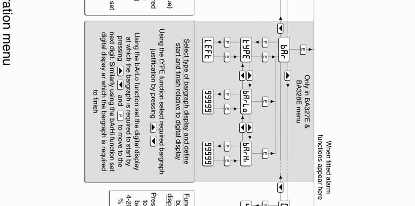
9 9 6. CONFIGURATION AND CALIBRATION Indicators are configured and calibrated via the four front panel push-buttons. All the configuration functions are contained in an easy to use intuitive menu that is shown diagrammatically in Fig 7. Each menu function is summarised in section 6.1 and includes a reference to more detailed information. When the indicator is fitted with alarms additional functions are added to the menu which are described in section 9.3 Throughout this manual push-buttons are shown as P, E, or, and legends displayed by the indicator are shown within inverted commas e.g. 'CAL' and ' ALr2'. Access to the configuration menu is obtained by operating the P and E push-buttons simultaneously. If the indicator security code is set to the default 0000 the first parameter 'FunC' will be displayed. If a security code other than the default code 0000 has already been entered, the indicator will display 'CodE'. Pressing the P button will clear this prompt allowing each digit of the code to be entered using the and pushbuttons and the P button to move control to the next digit. When the correct four digit code has been entered pressing E will cause the first parameter 'FunC' to be displayed. If the code is incorrect, or a button is not pressed within twenty seconds, the indicator will automatically return to the display mode. Once within the configuration menu the required parameter can be reached by scrolling through the menu using the and push-buttons as shown in Fig 6. When returning to the display mode following recalibration or a change to any function, the indicator will display data followed by SAVE while the new information is stored in non-volatile memory. All new indicators are supplied calibrated as requested at the time of ordering. If calibration is not requested, indicators will be configured as follows: BA307E BA327E BA308E BA328E Access code CodE Function FunC Std Std Display at 4mA Zero Display at 20mA SPAn Resolution resn 1 digit 1 digit Bargraph start BarLo Bargraph finish BarHi P button in display mode C P % % Tare tare Off Off Default configuration can easily be changed onsite. 6.1 Summary of configuration functions This section summarises each of the main configuration functions and includes a cross reference to a more detailed description. Fig 7 illustrates the location of each function within the configuration menu. The lineariser and the optional factory fitted alarms are described separately in sections 7 and 9.3 of this manual. Display Summary of function 'FunC' 'resn' 'dp' 'CAL' 'SEt' 'bar' Indicator function Defines the relationship between the 4/20mA input current and the indicator display. May be set to: Std Standard linear relationship root Lin See section 6.2 Square root extraction 16 segment adjustable lineariser see section 7. Display resolution Defines the resolution of the least significant display digit. May be set to 1, 2, 5 or 10 digits. See section 6.3 Decimal point Positions a dummy decimal point between any of the digits or turns it off. See section 6.4 Calibration of the digital display using an external current source. Enables the zero and span of the indicator to be adjusted using an external current source such as a calibrator. When used with an accurate traceable current source this is the preferred method of calibration. See section 6.5 Calibration of display using internal references. Enables the zero and span of the indicator to be adjusted without the need for an accurate input current or disconnection from the 4/20mA loop. See section 6.6 Bargraph format and calibration Only BA327E & BA328E have bargraph The bargraph may be conditioned to start from left, right or centre of the display, or it may be disabled. When optional alarms are fitted it can also display both alarm setpoints and the measured value. The bargraph may be calibrated to start and finish at any value within the indicator s calibrated digital display. See section 6.7
10 10
11 11 Display Summary of function 'C - - P' Function of P push-button The indicator may be configured to display the input current in milliamps, or the input current as a percentage of the 4/20mA input when the P push-button is operated in the display mode. See section Indicator function: FunC This configuration function defines the relationship between the indicator s 4/20mA input current and the indicator s display. Three alternatives are available: Std Standard linear relationship root Lin Square root extraction 16 segment adjustable lineariser. 'tare' Tare function When enabled the tare function sets the indicator display to zero when the E push-button is operated in the display mode. See section 6.9 To reveal the existing indicator function select 'FunC' from the configuration menu and press P. If the function is set as required, press E to return to the menu, or press the or button to change the setting, followed by the E button to return to the configuration menu. 'CodE' 'rset' Security code Defines a four digit numeric code that must be entered to gain access to the configuration menu. Default code 0000 disables this security function and allows unrestricted access to all conditioning functions. See section 6.10 Reset Contains two sub-functions, ConF which returns the indicator to the default conditions and LtAb which returns the lineariser to the default conditions. To prevent accidental use both resets must be confirmed by entering 5urE before they will be executed. See section 6.11 Std root Linear Provides a linear relationship between the 4/20mA indicator input current and the indicator display. Square root extraction Primarily intended to linearise the square law 4/20mA output from differential flowmeters. For reference, the following table shows the output current from a non-linearised differential flowmeter. % of full flow Current output ma When the root function is selected the indicator will display flow in linear units. Lin 16 segment adjustable lineariser Enables non linear variables to be displayed by the indicator in linear engineering units. Use of the lineariser is described in section 7 of this instruction manual. 6.3 Resolution: resn This function defines the resolution of the least significant display digit. Decreasing the display resolution can improve the readability of a noisy signal. Select ''resn' from the menu and press P which will reveal the current display resolution. To change the resolution press the or button to select 1, 2, 5 or 10 digits, followed by the E button to enter the selection and return to the configuration menu.
12 Position of the decimal point: dp A dummy decimal point can be positioned between any of the digits or it may be absent. To position the decimal point select 'dp' from the menu and press P. The decimal point can be moved by pressing the or push-button. If a decimal point is not required it should be positioned beyond the most or least significant digit. When positioned as required press the E button to enter the selection and return to the configuration menu. 6.5 Calibration using an external current source: CAL This function enables the zero and span of the indicator to be adjusted using an external calibrated current source. When used with an accurate traceable current source this is the preferred method of calibration. Zero is the indicator display with 4mA input Span is the indicator display with 20mA input To calibrate the indicator select 'CAL' from the configuration menu and press P. The indicator will display 'ZEro' which is a request for a 4mA input current. Adjust the external current calibrator to 4.000mA and again press P which will reveal the current zero display. The flashing digit of the indicator display can be changed by pressing the or buttons, when set as required pressing P will transfer control to the next digit. When all the digits have been adjusted, press E to enter the new zero and return to the 'ZEro' prompt. Pressing the button will cause the indicator to display 'SPAn' which is a request for a 20mA input current. Adjust the external current calibrator to mA and again press P which will reveal the existing span display. The flashing digit of the indicator display can be changed by pressing the or buttons, when set s required pressing P will transfer control to the next digit. When all the digits have been adjusted press E to enter the new span and return to the 'SPAn' prompt. Finally press E again to return to the configuration menu. Notes: a. The indicator input current must be adjusted to the required value before the zero and span functions are entered by pressing the P button. b. Indicators may be calibrated at currents other than 4 and 20mA, withiin the range 3.8 to 21.0mA providing the difference between the two currents is greater than 4mA. If these conditions are not complied with, the indicator displays FaiL and aborts the calibration. c. If the zero current is greater than the span current the instrument will be reverse acting i.e. an increasing input current will cause the display to decrease. 6.6 Calibration using internal reference: SEt Using the SEt function the indicator can be calibrated without the need for an accurate external current source and without the need to disconnect the indicator from the 4/20mA measuring loop. The indicator s internal reference is used to simulate a 4mA and 20mA input current, so the actual indicator input input current does not have to be known during calibration. Zero is the display with a simulated 4mA input Span is the idisplay with a simulated 20mA input To calibrate the indicator display select 'SEt' from the configuration menu and press P. The indicator will display 'ZEro', pressing P again will reveal the current display at 4mA. The flashing digit can be adjusted by pressing the or buttons, when the flashing digit is correct pressing P will transfer control to the next digit. When all the digits have been adjusted, press E to return to the 'ZEro' prompt. To adjust the display at 20mA, press the button which will cause the indicator to display 'SPAn', pressing P will then reveal the indicator s exisitng display at 20mA. The flashing digit can be adjusted by pressing the or buttons, when the flashing digit is correct pressing P will transfer control to the next digit. When all the digits have been adjusted press E to return to the 'SPAn' prompt followed by E to return to the SEt prompt in the configuration menu. 6.7 Bargraph format and calibration: bar Only BA327E & BA328E have a bargraph In addition to a five digit numerical display the two BA327E and BA328E indicators have a 31 segment analogue bargraph which may be configured to start and finish anywhere within the indicators numerical display range. To configure the bargraph select 'bar' from the configuration menu and press P. The indicator will display 'type', pressing P again will reveal the existing bargraph justification which can be changed to one of the following four or five options using the or button: Bargraph starts from LEFt Left end of display CEntr Centre of display right Right end of display AlrSP Only with alarms see section off Bargraph disabled When set as required press E to return to the type sub-function prompt.
13 13 The indicator s digital display at which the bargraph starts is defined by the barlo subfunction which is selected by pressing the button followed by the P button which will reveal the current indicator display at which the bargraph starts. The flashing digit can be adjusted by pressing the or buttons, when set as required pressing P will transfer control to the next digit. When all the digits have been adjusted, press E to return to the 'barlo' prompt from which barhi which defines the finishing point of the bargraph can be selected by pressing the button. barhi is adjusted in the same way as barlo. When set as required, pressing E twice will return the display to the bar prompt in the configuration menu. Note: barlo must be set lower than barhi, incorrect setting is indicated by the bargraph scale flashing with a single bargraph segment activated. 6.8 Function of the P push-button: C - - P When the indicator is in the display mode, operating the P push-button will display the input current in milliamps, or the displayed value as a percentage of the difference between the displayed values at 4mA and 20mA inputs. To check or change the function of the P pushbutton select 'C - -P' from the configuration menu and press P to reveal the current setting. Pressing the or button will toggle the setting between '4-20' the current display in milliamps and 'PC' the percentage display. When set as required press E to return to the C - - P prompt in the configuration menu. 6.9 Tare function: tare The tare function is primarily intended for use with weighing system. When the indicator is in the display mode and the tare function is activated, pressing the E button for more than three seconds will zero the indicator s digital display and activate the tare annunciator. On models with a bargraph, the bargraph remains linked to the digital display when the tare function is activated. Subsequent operation of the E push-button for less than 3 seconds will return the indicator to the gross display and deactivate the tare annunciator. To check or change the tare function select 'tare' from the configuration menu and press P to reveal the current setting. Pressing the or button will toggle the setting between 'on' and 'off'. When set as required press E to return to the tare prompt in the configuration menu Security code: CodE Access to the instrument configuration menu may be protected by a four digit security code which must be entered to gain access. New instruments are configured with the default security code 0000 which allows unrestricted access to all configuration functions. To enter a new security code select 'CodE' from the configuration menu and press P which will cause the indicator to display the existing security code with one digit flashing. The flashing digit can be adjusted using the and push-buttons, when set as required operating the P button will transfer control to the next digit. When all the digits have been adjusted press E to return to the CodE prompt. The revised security code will be activated when the indicator is returned to the display mode. Please contact BEKA associates sales department if the security code is lost Reset to factory defaults: rset This function enables the indicator and the lineariser to be quickly returned to the factory default configurations shown in sections 6 and 7. To reset the indicator or lineariser select rset from the configuration menu and press P, the indicator will display one of the reset options ConF or LtAb. ConF LtAb Resets the indicator to defaults Resets the lineariser to defaults Using the or push-button select the required sub-function and press P. To prevent accidental resetting the request must be confirmed by entering 5urE. Using the button set the first flashing digit to 5 and press P to transfer control to the second digit which should be set to u. When 5urE has been entered pressing the E button will reset the selected configuration menus and return the display to the rset function in the configuration menu Under and over-range If the numerical display range of the indicator is exceeded, all the decimal points will flash as shown below: BA307E BA327E BA308E BA328E Underrange Overrange Although not guaranteed, most indicators will continue to function normally with an input current between 1.8mA and 4mA, at lower currents the instrument will display LPLo before it stops functioning. Under or overrange of the BA327E and BA328E bargraph is indicated by an activated arrow at the appropriate end of the bargraph and a flashing bargraph scale.

14 14 7. LINEARISER A sixteen segment, seventeen breakpoint (0 to 16) lineariser may be selected in the FunC section of the configuration menu. The starting point and slope of each straight line segment are fully adjustable allowing the indicator to display most non-linear process variables in linear engineering units. Each break-points must occur at a current greater than the preceeding break-point and less than the following break-point, in the range 3.8 to 21.0mA Fig 8 shows a typical linearised indicator characteristic. level sensor in an irregular tank may be displayed in linear volumetric units by filling the tank with known incremental volumes and calibrating the indicator to display the sum of the increments at each break-point. The number of break-points required should first be entered using the 'Add' and 'del' functions. In both these sub-functions the indicator initially displays the current break-points and the total number of break-points being used as shown below. Display 'Add' Description of function Add a break-point Adds a new break-point before the displayed break-point. The calibration of existing break-points is not changed, but the identification number of all subsequent break-points is increased by one. Fig 8 shows a typical linearising characteristic Selecting Lin in the FunC section of the configuration menu activates the lineariser, this does not change the configuration menu shown in Fig 7, but the 'CAL' and 'SEt' functions are extended as shown in Fig 9. As with a linear indicator, calibration may be performed with an external current source using the 'CAL' function, or with the internal reference using the 'SEt' function. The lineariser configuration is retained irrespective of how the the indicator function FunC is subsequently changed. It is therefore possible to select and deselect the lineariser without having to reconfigure it each time. 7.1 Lineariser calibration using an external current source. This method allows direct calibration of the lineariser with an exteral current source and is the preferred method when traceability is required. If the exact system non-linearity is unknown, this method also allows direct calibration from the variable to be displayed. e.g. the output from a 'del' Remove a break-point Removes the displayed break-point and joins the preceding break-point to the following break-point with a straight line. The identification number of all subsequent break-points is decreased by one. To add a break-point using the or button select 'CAL' from the configuration menu and press P which will result in the 'Add' sub-function prompt being displayed. To enter the sub-function press P which will reveal the current break-point and the total number of break-point which have already been entered. Each subsequent operation of the P push-button will introduce an additional breakpoint up to the maximum of 17. When adding a break-point to a calibrated indicator, the insertion position for the new break-point can be selected using the and push-buttons. The delete break-point sub-function 'del' operates in exactly the same way as the 'Add' sub-function described above. Once within the del subfunction each time the P button is pressed a breakpoint is removed. When deleting a break-point from a calibrated indicator, the break-point to be deleted can be selected using the and pushbuttons. The minimum number of breakpoints is 2, break-points 0 and 1.
15 15
16 16 When the required number of break-points have been entered, return to the linearisation sub-menu by pressing E. The indicator will display the 'Add' or 'del' prompt depending upon the last function used. Now that the number of break-points has been entered, the input current at which each occurs and the corresponding indicator display can be defined by the Pts sub-function. Using the or button select 'PtS' from the submenu and press P which will select the first breakpoint '0 : n', where n is the total number of breakpoints entered. The selected break-point can be changed using the and buttons. When the required break-point has been selected, set the indicator input current to the exact value at which the break-point is required and press P. Then using the and buttons and the P button to move between digits, enter the required indicator display at this break-point. When set as required, press the E push-button to enter the required indicator display at this breakpoint and return to the sub-menu from which the next beak-point can be selected. 'del' 'in' 'disp' Remove a break-point Removes the displayed break-point and joins the preceding break-point to the following break-point with a straight line. The identification number of all subsequent break-points is decreased by one. Defines the current at which breakpoint occurs Enables the required current at each break-point to be defined without having to input an accurate input current to the indicator. Defines indicator display at breakpoint Enables the indicator display at each break-point to be defined. The number of break-points required should first be entered using the 'Add' and 'del' subfunctions. In both these sub-functions the indicator initially displays the current break-point and the total number of break-point being used as shown below. When all the break-points have been calibrated pressing E twice will return the indicator to the CAL function in the configuration menu. Note: The indicator input current must be adjusted to the required value before the P button is operated to enter the required indicator display. 7.2 Lineariser calibration using the internal reference. The SEt function enables the lineariser to be calibrated without the need for an accurate external current source. Throughout the calibration the indicator input current may be any value between 4 and 20mA. The SEt functions contains four sub-functions. To add a break-point, using the or button select 'SEt' from the configuration menu and press P which will result in the 'Add' sub-function prompt being displayed. To enter the sub-function press P which will reveal the current break-point and the total number of break-points which have already been entered. Each subsequent operation of the P push-button will introduce an additional breakpoint up to the maximum of 17. When adding a break-point to a calibrated indicator, the insertion position for the new break-point can be selected using the and push-buttons. Display 'Add' Description of function Add a break-point Adds a new break-point before the displayed break-point. The calibration of existing break-points is not changed, but the identification number of all subsequent break-points is increased by one. The delete segment sub-function 'del' operates in exactly the same way as the 'Add' sub-function described above. Once within the del function each time the P button is pressed a break-point is removed. When deleting a break-point from a calibrated indicator, the break-point to be deleted can be selected using the and push-buttons. The minimum number of break-points is 2, breakpoints 0 and 1.
17 17 When the required number of break-points has been entered, return to the linearisation sub-menu by pressing E. The indicator will display the 'Add' or 'del' prompt depending upon the last subfunction used. The indicator input current and corresponding indicator display at each breakpoint, can now be entered using the in and disp sub-functions. Using the or button select 'in' from the submenu and press P which will reveal the first breakpoint '0 : n', where n is the total number of breakpoints entered. Press P and use the and buttons and the P button to move between digits, to enter the input current at which the first breakpoint is required, usually 4.000mA. When set as required, press E to return to the 0 : n prompt from which the the next break-point can be selected using the and buttons. When the required break-point has been selected press P and enter the indicator input current at which this break-point is required. Repeat this procedure until the indicator input current at all the break-points has been defined and then return to the in subfunction by pressing the E button. 7.4 Under and over-range The lineariser does not change the under and over-range indication described in section At input currents below that specified for the first break-point (0), the indicator will continue to use the specified slope of the first segment. Although not guaranteed, most indicators will continue to function normally with an input current between 1.8mA and 4mA, at lower currents the instrument will display LPLo before it stops functioning. At input currents above that specified for the last break-point, the indicator will continue to use the slope specified for the last lineariser segment. 7.5 Lineariser default configuration When the lineariser is reset to the default conditions using the rset reset function described in section 6.11, the defaults conditions are: BA307E BA327E BA308E BA328E First break-point 4mA Second break-point 20mA The corresponding indicator display at each of the break-points can now be defined with the disp sub-function Using the and buttons select the disp sub-function and press P which will reveal the first break-point '0 : n', where n is the total number of break-points entered. Press P and use the and buttons and the P button to move between digits, to enter the required indicator display at this first break-point. When set as required, press E to return to the 0 : n prompt from which the the next break-point can be selected using the or buttons. When the required break-point has been selected press P and set the required indicator display at this break-point. Repeat this procedure until the indicator display at all the break-points has been defined and then return to the SEt function in the configuration menu by pressing the E button twice. 7.3 Lineariser error message If an attempt is made to position a break-point at a current which is not greater than the current of the preceeding break-point, or at a current which is not less than the current of the following break-point, the error message FaiL will be displayed. This error message will also be displayed if an attempt is made to position a break-point outside the current range 3.8 to 21.0mA.
18 18 8. MAINTENANCE 8.1 Fault finding during commissioning If an indicator fails to function during commissioning the following procedure should be followed: Symptom Cause Solution No display Incorrect wiring Check wiring No display 0V between terminals 1 & 3. All decimal points flashing. Unstable display Unable to enter configuration menu. Incorrect wiring or no power supply Underrange if ve sign displayed or overrange. 4/20mA input is noisy. Incorrect security code entered. There should be 0.6 to 1.2V between terminals 1 & 3 with terminal 1 positive. With an optional loop powered backlight, there should be 3.4 to 5V between terminals 3 & 12 with terminal 12 positive. Check supply voltage and voltage drop caused by all the instruments in the loop. Recalibrate the numerical display. Eliminate ripple on 4/20mA power supply and/or decrease indicator resolution. Enter correct security code, or contact BEKA if the code has been lost. 8.3 Servicing All BA307E, BA327E, BA308E and BA328E loop powered indicators are interchangeable if the required optional backlight and alarms are fitted. A single spare instrument may quickly be recalibrated to replace any instrument that is damaged or fails. No attempt should be made to repair instruments at component level. We recommend that faulty instruments are returned to BEKA associates or to your local BEKA agent for repair. 8.4 Routine maintenance The mechanical condition of the instrument and electrical calibration should be regularly checked. The interval between inspections depends upon environmental conditions. We recommend that initially instrument calibration should be checked annually. 8.5 Guarantee Indicators which fail within the guarantee period should be returned to BEKA associates or our local agent. It is helpful if a brief description of the fault symptoms is provided. 8.6 Customer comments BEKA associates is always pleased to receive comments from customers about our products and services. All communications are acknowledged and whenever possible, suggestions are implemented. 8.2 Fault finding after commissioning ENSURE PLANT SAFETY BEFORE STARTING MAINTENANCE Live maintenance is permitted on intrinsically safe equipment installed in a hazardous area, but only certified test equipment should be used unless a gas clearance certificate is available. If an indicator fails after it has been functioning correctly follow the procedure shown in section 8.1. If this does not reveal the cause of the fault, it is recommended that the instrument is replaced. This can be done without disconnecting power, but while the indicator is disconnected the 4/20mA loop will be open circuit.


19 19 9. ACCESSORIES 9.1 Scale card All models have a window on the right hand side of the display through which to view a scale card showing the units of measurement such as o C, mbar, RPM. New indicators are fitted with a scale card showing the units of measurement specified when the indicator was ordered, if the units are not specified a blank scale card will be fitted. A pack of scale cards pre-printed with common units of measurement is available as an accessory. These can easily be fitted on-site to the indicator without opening the indicator enclosure or removing it from the panel, See section 5.3 of this instruction manual. Custom scale cards for applications requiring less common units of measurement are also available. 9.2 Tag information New indicators are supplied with tag or application information thermally printed onto the rear panel adjacent to the terminals, legend as specified when the indicator was ordered. This tag information is not visible from the front of the instrument after installation. 9.3 Alarms CAUTION These alarms outputs should not be used for critical safety applications such as an emergency shut down system. All models can be supplied with factory fitted dual solid state, single pole alarm outputs. Each alarm output may be independently conditioned as a high or low alarm with a normally open or normally closed output in the non-alarm condition. When the 4/20mA current powering the indicator is removed both alarm outputs will open irrespective of configuration. The open circuit condition should therefore be chosen as the alarm condition when designing an alarm system. Fig 10 illustrates the conditions available and shows which are fail safe. When an alarm occurs an alarm annunciator on the indicator front panel is activated and if required the numerical display can alternate between the measured value and the alarm channel identification ALr1 or ALr2. CAUTION The alarms are activated by the indicator s numerical display. Use of the Tare Function tare will change the numerical display, the alarms will continue to function at the original displayed value, but this will correspond to a different input current. Fig 10 Alarm outputs Configurable functions for each alarm include adjustable setpoint, hysteresis, alarm delay and alarm accept Solid state output Each alarm has a galvanically isolated single pole solid state switch output which as shown in Fig 11. The output is polarised and current will only flow in one direction. Ron = less than 5Ω + 0.7V Roff = greater than 1MΩ Fig 11 Equivalent circuit of each alarm output Intrinsic safety Each alarm output is a separate galvanically isolated intrinsically safe circuit with output safety parameters complying with the requirements for simple apparatus. This allows the alarm output terminals 8 & 9 and 10 & 11 to be connected to almost any intrinsically safe circuit protected by a Zener barrier or galvanic isolator providing the output parameters of the circuit do not exceed: Uo = 30V dc Io = 200mA Po = 0.84W
20 20
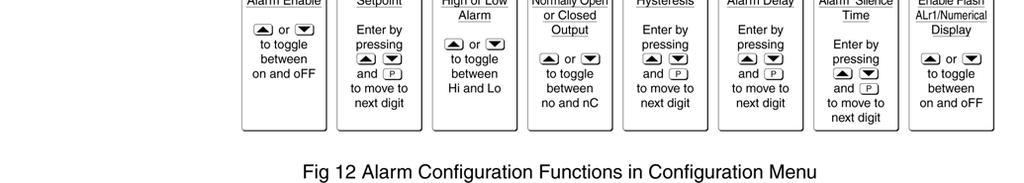
21 21 The maximum equivalent capacitance and inductance between each set of alarm terminals is: Ci = 24nF Li = 8µH (Effectively 0) To determine the maximum permissible cable parameters Ci should be subtracted from the maximum permitted cable capacitance specified by the certificate powering the alarm circuit, such as the solenoid driver and switch transfer galvanic isolators shown in Fig 13. Summary of alarm configuration functions Display Description of function 'EnbL Alarm enable Enables or disables the alarm without changing the alarm parameters. See section 'SP1' Alarm setpoint 1 Adjusts the alarm setpoint. The alarm is activated when the indicator display equals the setpoint. See section Fig 13 Typical alarm application (Shown without recommended screen cables) Configuration and adjustment When optional alarms are fitted to a loop powered indicator the configuration menu is extended as shown in Fig 12. The additional functions appear between the SEt and the C- - P functions for the BA307E and BA308E indicators, and between bar and C- -P for the BA327E and BA328E indicators. For simplicity, Fig 12 only shows the additional functions for alarm 1, but alarm 2 has identical functions. The following table summaries each of the alarm configuration functions and includes a cross reference to more detailed information. Again only the functions on alarm 1 are listed, but alarm 2 has identical facilities 'Hi.Lo' 'no.nc' 'HStr' 'dela' 'SiL' FLSH 'ACSP' Alarm function Defines the alarm function as High or Low. See section Normally open or normally closed output Sets the alarm output open or closed in the non-alarm condition. See section Hysteresis Adjusts the alarm hysteresis. See section Alarm delay time Introduces adjustable delay between the display equalling the setpoint and the alarm output being activated. See section Alarm silence time Defines the time that the alarm output remains in the non-alarm condition following acceptance of an alarm. See section Flash display when alarm occurs When enabled, alternates the numerical display between process value and alarm reference, ALr1 or ALr2, when an alarm output is activated. See section Access setpoint Sub-menu which enables direct access to the alarm setpoints from the indicator display mode, and defines a separate security code. See section
22 Alarm enable: EnbL This function allows each alarm to be enabled or disabled without altering any of the alarm parameters. To enable or disable the alarm select 'EnbL' from the alarm menu and press P which will reveal the current setting on or off. The function can be changed by pressing the or button followed by the E button to return to the alarm menu Setpoint adjustment: SP1 and SP2 The setpoint of each alarm may be positioned anywhere in the numerical display of the indicator providing that this corresponds to an input current between 3.8 and 20.2mA. e.g. If the indicator has been calibrated to display 0 with 4mA input and with 20mA input, the two alarm setpoints may be positioned anywhere between -125 and To adjust the setpoint select 'SP1' or 'SP2' from the alarm configuration menu and press P which will reveal the existing alarm setpoint. The flashing digit of the setpoint can be adjusted using the and push-buttons, and the P button to move control to the next digit. When the required setpoint has been entered press E to return to the alarm configuration menu. The alarm setpoints may also be adjusted when the indicator is in the display mode, see section Alarm function: Hi.Lo Each alarm can be independently conditioned as a high alarm or as a low alarm. To check or change the alarm function select 'Hi.Lo' from the alarm menu and press P to reveal the current setting. The function can be changed by pressing the or button followed by the E button to return to the alarm menu Alarm output status: no.nc Configures the solid state alarm output to be open no or to be closed nc in the non-alarm condition. When deciding which is required, care should be taken to ensure that the alarm output is fail safe as illustrated in Fig 10. no Alarm output open in non-alarm condition nc Alarm output closed in non-alarm condition CAUTION When the 4/20mA supply is removed from the loop powered indicator, both alarm outputs will open irrespective of conditioning. Therefore for fail safe operation both alarm outputs should be conditioned to be open in the alarm condition nc. To check or change the alarm output status, select 'no.nc' from the alarm configuration menu and press P to reveal the setting. The function may be changed by pressing the or button followed by the E button to return to the alarm configuration menu Hysteresis: HStr Hysteresis is shown in the units that the indicator has been calibrated to display. To adjust the hysteresis select 'HStr' from the alarm menu and press P which will reveal the existing figure. The flashing digit can be adjusted using the and push-buttons, and the P button will move control to the next digit. When the required hystersis has been entered press E to return to the alarm configuration menu. e.g. An indicator calibrated to display 0 to 10000, with a high alarm set at 9000 and hysteresis of 200 will perform as follows: The high alarm will be activated when increasing indicator display equals 9000, but will not reset until the indicator display falls below Alarm delay: dela This function delays activation of the alarm output for an adjustable time following the alarm condition occurring. The delay can be set in 1 second increments between 0 and 3600 seconds. If a delay is not required zero should be entered. To adjust the delay select 'dela' from the alarm configuration menu and press P which will reveal the existing delay. The flashing digit of the delay can be adjusted using the and push-buttons, and the P button to move control to the other digits. When the required delay has been entered press E to return to the alarm menu. e.g. An indicator with a high alarm set at 9000 and an alarm delay of 30 seconds will perform as follows: The alarm annunciator will start to flash when an increasing indicator display equals 9000, but the alarm output will not be activated until the alarm condition has existed continuously for 30 seconds. When the alarm output is activated, the alarm annunciator will stop flashing and become permanently activated. If the FLSH function, which flashes the indicator display when an alarm occurs, has been enabled, it will not start to function until the alarm output is activated. See section
23 Alarm silence time: SiL This function is primarily intended for use in small installations where the alarm output directly operates an alarm annunciator such as a sounder or beacon. When the alarm silence time, which is adjustable between 0 and 3600 seconds in 1 second increments, is set to any figure other than zero, the P push-button becomes an alarm accept button. After an alarm has occurred, operating the P button will cause the alarm output to revert to the non-alarm condition for the programmed alarm silence time. If the alarm condition still exists at the end of the silence time, the alarm output will be reactivated. During the silence time the indicator alarm annunciator will flash until the silence time expires or the alarm is cleared. If the FLSH function, which flashes the indicator display when an alarm occurs has been enabled, it will only function when the alarm output is activated, not during the silence time. See section To adjust the alarm silence time select 'SiL' from the alarm configuration menu and press P which will reveal the existing silence time. The flashing digit of the silence time can be adjusted using the and push-buttons, and the P button to move control to the other digits. When the required silence time has been entered press E to return to the alarm menu Flash display when alarm occurs FLSH In addition to the two alarm annunciators on the top left hand corner of the indicator display which show the status of both alarms, this function provides an even more conspicuous indication that an alarm condition has occurred. When enabled, the function alternates the indicator display between the numerical value and the alarm reference, ALr1 or ALr2, when the alarm output is activated. If both alarm outputs are activated, the alarm references are displayed in sequence. To enable or disable the function select 'FLSH' from the alarm menu and press P which will reveal the current setting on or off. The function can changed by pressing the or button followed by the E button to return to the alarm menu Access setpoint in display mode: ACSP This function enables a separate menu providing access to the alarm setpoints from the display mode by simultaneously operating the P and push-buttons. An operator can therefore adjust the alarm setpoints without having access to the indicator configuration menu. Protection against accidental adjustment of the setpoints when the indicator is in the display mode is provided by a separate security code. This direct setpoint access menu is enabled and the separate security code entered from the 'ACSP' function in the alarm configuration menu as shown in Fig 12. To change the menu parameters select 'ACSP' from the configuration menu and press P which will display the enable prompt 'EnbL'. Press P again to reveal if the direct access menu is 'on' or 'off'. The or button will toggle the display between the two conditions. If 'off' is selected, the operator will not have access to the setpoints from the display mode. Return to the 'ACSP' prompt in the main menu by pressing E twice. If 'on' is selected, the operator will have direct access to the alarm setpoints from the display mode via a separate optional security code. To define this four digit security code press P to return to the 'Enbl' prompt followed by the or button to select the access code prompt 'ACCd'. Pressing P will reveal the current security code. Each digit of the code may be changed by operating the and push-buttons, and the P button to move control to the next digit. When the required code has been entered, press E twice to return to the 'ACSP' prompt in the configuration menu. Default code 0000 will disable the security code allowing direct access to the setpoints in the display mode by pressing the P and buttons simultaneously. Unless otherwise requested new instruments with alarms are supplied with this function disabled and the security code set to Adjusting alarm setpoints from the display mode Access to the alarm setpoints from the indicator display mode is obtained by operating the P and push-buttons simultaneously as shown in Fig 14. If the setpoints are not protected by a security code the alarm setpoint prompt 'SP1' will be displayed. If the setpoints are protected by a security code, 'Code' will be displayed first. Pressing P again will enable the alarm security code to be entered digit by digit using the and buttons to change the flashing digit, and the P push-button to move control to the next digit. If the correct code is entered pressing E will cause alarm setpoint prompt 'SP1' to be displayed. Pressing the or button will toggle the display between the two alarm setpoint prompts 'SP1' and 'SP2'. If an incorrect security code is entered, or a button is not pressed within twenty seconds, the indicator will automatically return to the display mode.
24 Displaying setpoints on bargraph One of the selectable bargraph formats AlrSP allows a low or a high setpoint plus the displayed value to be represented, or a low and a high setpoint plus the displayed value to be represented by the bargraph as shown in Fig 15. Fig 15 Displayed value and setpoints on bargraph The bargraph area below the low alarm setpoint and the area above the high alarm setpoint are activated. The displayed variable is represented by an activated bar which moves between these low and high alarm setpoints. Fig 14 Setpoint adjustment from the display mode To adjust an alarm setpoint select 'SP1' or 'SP2' and press P which will reveal the current setting. Each digit of the setpoint may be adjusted using the and push-buttons, and the P button to move control to the next digit. When the required setpoint has been entered, pressing E will return the display to the 'SP1' or 'SP2' prompt from which the other setpoint may be selected, or the indicator may be returned to the display mode by pressing E again. When the activated bar representing the displayed variable is adjacent to the area representing the low or high ararm setpoints, the bar flashes. When a displayed variable equals the low or high alarm the complete bargraph representing the activated alarm flashes irrespective of whether the alarm output has been delayed or cleared. For this function to operate SP1 must be conditioned as a low alarm and SP2 as a high alarm; SP1 must always be less than SP2. Incorrect configuration is shown by a flashing bargraph scale with no activated bars. Note: With the indicator in the display mode, direct access to the alarm setpoints is only available when the ACSP menu is enabled - see section

25 Display backlight The BA307E, BA327E, BA308E and BA328E loop powered indicators can be supplied with a factory fitted backlight that may be loop or separately powered Separately powering the backlight The optional backlight may also be powered from a separate safe area power supply via an intrinsically safe interface as shown in Fig 18. When loop powered the backlight produces green background illumination enabling the display to be read at night or in poor lighting conditions. No additional power supply, intrinsic safety interface or field wiring are required, but the indicator voltage drop is increased. When separately powered the backlight is brighter, but an additional intrinsic safety interface and field wiring are required. Fig 16 Terminals for optional backlight Loop powering the backlight The backlight is loop powered by connecting it in series with the indicator 4/20mA input as shown in Fig 17, which increases the maximum indicator voltage drop from 1.2 to 5V. Fig 18 Separately powered backlight When separately powered the backlight draws a constant current when supply is equal to or greater the minimum specified voltage. Below this supply voltage the backlight continues to function but with reduced brilliance. Current Minimum voltage BA307E & BA327E 22.5mA 9.0V BA308E & BA328E 34.7mA 11.0V Any certified Zener barrier or galvanic isolator may be used, providing the output parameters do not exceed: Uo = 30V dc Io = 200mA Po = 0.84W Fig 17 Loop powered backlight The input intrinsic safety parameters of the combined indicator and backlight are the same as for the indicator alone. The EC-Type Examination Certificate states that for intrinsic safety considerations, under fault conditions the output voltage, current and power of the combined indicator and backlight terminals 1 & 13 will not exceed those specified by clause 5.7 of EN for simple apparatus, which simplifies system design and documentation. Providing the increased voltage drop can be tolerated, the intrinsic safety and system design described in sections 3 and 4 of this manual remain valid with the loop powered backlight. The internal capacitance Ci between terminals 12 & 14 should be subtracted from Co of the intrinsically safe interface powering the backlight to determine the maximum permissible cable capacitance. Ci = 13nF Li = 8µH (Effectively 0) Two separately powered BA307E or BA327E indicator backlights may be connected in parallel to a single channel 28V, 93mA Zener barrier or galvanic isolator with no noticeable reduction in brilliance on a 24V dc supply.
26 26 Appendix 1 Dust certification A1.0 ATEX dust certification In addition to ATEX certification permitting installation in explosive gas atmospheres which is described in the main section of this instruction manual, all BA307E, BA327E, BA308E and BA328E indicators have ATEX certification permitting installation in combustible dust atmospheres. This appendix describes ATEX installations in explosive dust atmospheres conforming with EN Electrical installations design, selection and erection. When designing systems for installation outside the UK the local Code of Practice should be consulted. The indicator s dust input and output safety parameters are identical to gas parameters, so all the electrical circuits shown in the main section of this manual may also be used for dust applications. A1.1 Zones, and Maximum Surface Temperature The BA307E, BA327E, BA308E and the BA328E have been ATEX certified as Group II, Category 1D Ex ia IIIC T80ºC Da IP20 apparatus, Ta -40 to 70 C. When connected to a suitable system the indicators may be installed in: Zone 20 Zone 21 Zone 22 explosive atmosphere in the form of a cloud of combustible dust in air is continuously present, or for long periods or frequently. explosive atmosphere in the form of a cloud of combustible dust in air is likely to occur occasionally in normal operation. explosive atmosphere in the form of a cloud of combustible dust in air is not likely to occur in normal operation, but if it does occur, will only persist for a short period. Be used with dust in subdivisions: Having a Minimum Ignition Temperature of: Dust cloud 120 C Dust layer on indicator up to 5mm thick 155 C Dust layer on indicator Refer to over 5mm thick. EN At an ambient temperature between -40 and +70 C A1.3 Maintenance ENSURE PLANT SAFETY BEFORE STARTING MAINTENANCE Live maintenance is permitted on intrinsically safe equipment installed in a hazardous area, but only certified test equipment should be used. All models have IP66 front of panel protection and a gasket is provided to seal the joint between the instrument and the mounting panel thus preventing dust ingress from the outside of the mounting panel. The rear of the instruments is not sealed, but ATEX dust certification is dependent on the internal conformal coating of the instrument, so dust ingress is acceptable except for use in IIIC conductive dusts see A1.4. However, it is good practice to minimise the amount of dust accumulating on the rear of the instrument. A1.4 Special conditions for use in IIIC dusts The ATEX certificate for the loop powered indicators has an X suffix indicating that special conditions for safe use are required for installion in IIIC dust atmospheres, the certificate states: For use in Group IIIC conductive gas atmospheres, the indicator shall be mounted such that the instrument terminals have at least IP6X protection. To prevent the indicator terminals becoming contaminated by conductive dust: The indicator must be installed in a panel, cubicle or enclosure providing a minimum of IP6X protection. IIIA IIIB IIIC combustible flyings non-conductive dust conductive dust (For use with IIIC conductive dusts special conditions for safe use apply see section A1.4) The gasket supplied to seal the joint between the indicator and the mounting panel must be used, and the 144 x 72mm BA308E and BA328E indicators must be secured with four panel mounting clamps. Note: These special installation conditions only apply for indicators exposed to IIIC conductive dust atmospheres.
27 27 Appendix 2 IECEx certification A2.0 The IECEx Certification Scheme IECEx is a global certification scheme for explosion protected products which aims to harmonise international certification standards. For additional information about the IECEx certification scheme and to view the BEKA associate certificates, please visit A2.1 IECEx Certificate of Conformity The BA307E, BA327E, BA308E and the BA328E loop powered indicators and the optional accessories have been issued with an IECEx Certificate of Conformity number IECEx ITS X which specifies the following certification codes: Ex ia IIC T5 Ga Ex ia IIIC T80ºC Da Ta = -40ºC to 70ºC The specified gas and dust intrinsic safety parameters are identical to the ATEX safety parameters described in this manual. A2.3 Special conditions for use in IIIC dusts The IECEx certificate for the loop powered indicators has an X suffix indicating that special conditions for safe use are required for installion in IIIC dust atmospheres, the certificate states: For use in Group IIIC conductive gas atmospheres, the indicator shall be mounted such that the instrument terminals have at least IP6X protection. To prevent the indicator terminals becoming contaminated by conductive dust: The indicator must be installed in a panel, cubicle or enclosure providing a minimum of IP6X protection. The gasket supplied to seal the joint between the indicator and the mounting panel must be used, and the 144 x 72mm BA308E and BA328E indicators must be secured with four panel mounting clamps. Note: These special installation conditions only apply for indicators exposed to IIIC conductive dust atmospheres. The IECEx certificate may be downloaded from or requested from the BEKA sales office. A2.2 Installation The IECEx and ATEX certificates specify identical safety parameters and installation requirements for both approvals as defined by IEC / EN The ATEX gas and dust installation requirements specified in section 5 and Appendix 1 of this manual may therefore be used for IECEx installations, but the local code of practice should also be consulted.
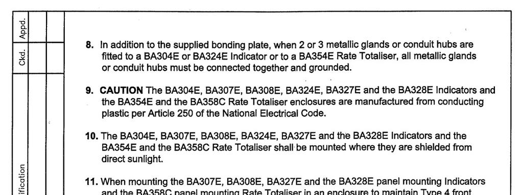
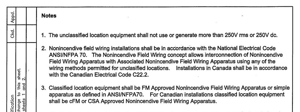
28 28 Appendix 3 FM Approval for use in the USA and cfm Approval for use in Canada A3.0 Factory Mutual Approval For installations in the USA and Canada, all models have FM and cfm intrinsic safety and nonincendive approval, project identifications and C. Copies of the Certificates of Compliance are available from the BEKA associates sales office and A3.1 Intrinsic safety approval The indicators are approved to FM Class 3610 intrinsic safety standard for use in Division 1 and 2 hazardous (classified) locatios. Installations must comply with BEKA associates Control Drawing CI300-72, which is attached to this appendix, ANSI/ISA RP Installation of Intrinsically Safe Systems for Hazardous (Classified) Locations and with the National Electrical Code ANSI/NFPA70. Installations in Canada must comply with the Canadian Electrical Code C22.2 The front of all the models have IP66 (Type 4X) protection. To obtain an IP66 seal between the indicator and the panel in which it is mounted, the installation must comply with note 11 of Control Drawing CI All the models have a T5 rating at ambient temperatures up to +70ºC and may be used with the following gases: Intrinsic Safety Division 1 or 2 Class I Group A & B Group C Group D Zone 0, 1 or 2 Class 1 Group IIC Group IIB Group IIA A3.2 Nonincendive approval All the models are FM Class 3611 nonincendive approved allowing installation in Division 2 hazardous (classified) locations without the need for Zener barriers or galvanic isolators. US installations must comply with the BEKA associates Control Drawing CI300-73, which is attached to this appendix, and with the National Electrical Code ANSI/NFPA70. Canadian nonincendive installations must comply with the Canadian Electrical Code C22.2 and with BEKA associates Control Drawing CI300-73, which is attached to this appendix. The front of all the models have IP66 (Type 4X) protection. To obtain an IP66 seal between the indicator and the panel in which it is mounted, the installation must comply with note 6 of Control Drawing CI All the models have a T5 rating at ambient temperatures up to +70ºC and may be used with the following gases: Nonincendive Division 2 Class I Group A & B Group C Group D Class II Groups E, F & G Class III Class I Zone 2 Group IIC Group IIB Group IIA The FM and cfm entity parameters are similar to the ATEX and IECEx parameters and the systems shown in section 4 of this manual may therefore also be used for FM and cfm installations.
29 29
30 30
31 31
32 32
33 33
34 34
35 35
36 36
37 37
BA374C Intrinsically safe field mounting indicating temperature transmitter
 BA374C Intrinsically safe field mounting indicating temperature transmitter Issue: 5 3rd December 2003 CONTENTS 1. Description 2. Operation 2.1 Controls 3. Intrinsic Safety Certification 3.1 ATEX certificate
BA338C Intrinsically safe Externally powered pulse input panel mounting rate totaliser issue 13
 BA338C Intrinsically safe Externally powered pulse input panel mounting rate totaliser issue 13 Certification information label Total display Rate display Rotating flow indicator Annunciators for optional
BA334D Intrinsically safe Externally powered pulse input field mounting rate totaliser Issue 13
 TR Automatyka Sp. z o. o. Tel. (+48 022) 886 10 16 www.trautomatyka.pl ul. Lechicka 14 ; 02-156 Warszawa Fax. (+48 022) 846 50 37 biuro@trautomatyka.pl BA334D Intrinsically safe Externally powered pulse
BA554D 4/20mA loop-powered field mounting rate totaliser
 BA554D 4/20mA loop-powered field mounting rate totaliser Issue: 1 September 2000 2 CONTNTS 1. Description 2. Operation 2.1 Controls 2.2 Displays 3. System Design 3.1 Flow transmitter loops 3.2 Remote indication
INSTRUCTION MANUAL IS-mB1 Minialite Intrinsically Safe Round LED Beacon
 INSTRUCTION MANUAL Minialite Intrinsically Safe Round LED This instruction sheet describes installations which conform to EN60079:Part14:2008 Electrical Installation in Hazardous Areas. When designing
4) Intrinsic Safety Certification
 Intrinsic Safety Certification") INSTRUCTION MANUAL Minialert Intrinsically Safe Round Combined Unit Section Volume Control Tone Generator S2 S3 Tone Selection Switches Fig 1 Simplified block diagram The combined unit is CE marked for
INSTRUCTION MANUAL Minialert Intrinsically Safe Round Combined Unit Section Volume Control Tone Generator S2 S3 Tone Selection Switches Fig 1 Simplified block diagram The combined unit is CE marked for
BA488CF Intrinsically safe Panel mounting Fieldbus Display
 BA488CF Intrinsically safe Panel mounting Fieldbus Display Issue: 8 Issue: 8 8 th May 2006 2 CONTENTS 1. Description 1.1 Documentation 1.2 Version 2.0 firmware 2. Operation 2.1 Controls 3. Intrinsic Safety
INSTRUCTION MANUAL (ATEX)
") INSTRUCTION MANUAL (ATEX) ISmA1M Minialarm Intrinsically Safe Round ISmA1M Volume Control Tone Generator S3 Tone Selection Switches Fig 1 Simplified block diagram The ISmA1M sounder is CE marked for compliance
INSTRUCTION MANUAL (ATEX) ISmA1M Minialarm Intrinsically Safe Round ISmA1M Volume Control Tone Generator S3 Tone Selection Switches Fig 1 Simplified block diagram The ISmA1M sounder is CE marked for compliance
OilSET Installation and Operating Instructions. Oil Separator Alarm Device with SET/DM3AL sensor
 Labkotec UK Ltd Adminicle House 1 Lumb Lane Audenshaw Manchester M34 5WH GREAT BRITAIN Tel: 0844 3350 477 Fax: 0161 4281 179 E-mail: info@labkotec.co.uk 10.8.2012 Internet: www.labkotec.co.uk 1/13 OilSET-1000
Software Version 2.01 LEVEL MONITOR MODEL 220
 Software Version 2.01 LEVEL MONITOR MODEL 220 19 April 2000 CONTENTS 1. Introduction 1 1.1 Model Number Designation 2 1.2 Intrinsic Safety Considerations 3 2. Specification 4 3. Operation 6 3.1 Display
SET Installation and Operating Instructions. Level switch for one sensor
 Labkotec Oy Myllyhaantie 6 FI-33960 PIRKKALA FINLAND Tel.: +358 29 006 260 Fax: +358 29 006 1260 7.11.2013 Internet: www.labkotec.fi 1/14 SET-1000 Level switch for one sensor Copyright 2013 Labkotec Oy
RTK Instruments Limited St James Business Park, Knaresborough, North Yorkshire, England. HG5 8PJ
 Operating Instructions RTK Instruments Limited Telephone: 44 (0)1423 580500 Facsimile: 44 (0)1423 580501 DA135 Intrinsically Safe LED Beacon Introduction This manual provides the information necessary
Analox 1000 Series. User Manual. Analox Sensor Technology Ltd. 15 Ellerbeck Court, Stokesley Business Park North Yorkshire, TS9 5PT, UK
 Analox 1000 Series User Manual Analox Sensor Technology Ltd. 15 Ellerbeck Court, Stokesley Business Park North Yorkshire, TS9 5PT, UK T: +44 (0)1642 711400 F: +44 (0)1642 713900 W: www.analox.net E: info@analox.net
E2S Datasheet v10a. The IS-mA1 is suitable for all intrinsically safe signalling applications including fire, security and process control.
 E2S Datasheet 1.2.1 v10a ISmA1 ISminialarm The ISmA1 is a compact, 100dB(A) alarm sounder. Approvals include ATEX, IECEx and GOSTR for Zone 0 applications and FM approval for Class I Division 1 and Class
SET-2000 Oil/Sludge 12 VDC
 Labkotec Oy Myllyhaantie 6 FI-33960 PIRKKALA FINLAND Tel: + 358 29 006 260 Fax: + 358 29 006 1260 12.2.2015 Internet: www.labkotec.fi 1/14 SET-2000 Oil/Sludge 12 VDC Alarm Device for Oil Separators with
DB5 Intrinsically Safe Sounder Type DB-5
 Operating Instructions RTK Instruments Limited DB5 Intrinsically Safe Sounder Type DB-5 Description The DB5 Sounder is a strong, lightweight warning sounder, CENELEC certified to Ex II 1G EExia IIC T4
INSTRUCTION MANUAL (ATEX/IECEx/SIL2) BExBG05D-SIL Flameproof Xenon SIL 2 Beacons For use in Flammable Gas and Dust Atmospheres
 BExBG05D-SIL Flameproof Xenon SIL 2 Beacons For use in Flammable Gas and Dust Atmospheres") INSTRUCTION MANUAL (ATEX/IECEx/SIL2) BExBG05D-SIL Flameproof Xenon SIL 2 Beacons For use in Flammable Gas and Dust Atmospheres 1) Introduction The BExBG05D-SIL is a flameproof beacon which is certified
INSTRUCTION MANUAL (ATEX/IECEx/SIL2) BExBG05D-SIL Flameproof Xenon SIL 2 Beacons For use in Flammable Gas and Dust Atmospheres 1) Introduction The BExBG05D-SIL is a flameproof beacon which is certified
OilSET Installation and Operating Instructions. Oil Separator Alarm Device
 Labkotec Oy Myllyhaantie 6 FI-33960 PIRKKALA FINLAND Tel: +358 29 006 260 Fax: +358 29 006 1260 18.11.2010 Internet: www.labkotec.fi 1/10 OilSET-1000 Oil Separator Alarm Device Copyright 2010 Labkotec
SET-2000 Hi Level/Oil
 Labkotec Oy Labkotie 1 FI-36240 KANGASALA FINLAND Tel: + 358 29 006 260 Fax: + 358 29 006 1260 13.03.2008 Internet: www.labkotec.fi Alarm Device for Oil Separators Copyright 2008 Labkotec Oy We reserve
VERSAFLOW VORTEX Supplementary instructions
 VERSAFLOW VORTEX Supplementary instructions Vortex flowmeter Equipment category II 2G CONTENTS VERSAFLOW VORTEX 1 Safety instructions 3 1.1 General notes... 3 1.2 EC conformity... 3 1.3 Approval according
INSTRUCTION MANUAL (ATEX / IECEx)
") INSTRUCTION MANUAL (ATEX / IECEx) BExS110D and BExS110D-R Sounder For use in Flammable Gas and Dust Atmospheres BExS110D BExS110D-R 1) Warnings DO NOT OPEN WHEN AN EXPLOSIVE ATMOSPHERE IS PRESENT DO NOT
INSTRUCTION MANUAL (ATEX / IECEx) BExS110D and BExS110D-R Sounder For use in Flammable Gas and Dust Atmospheres BExS110D BExS110D-R 1) Warnings DO NOT OPEN WHEN AN EXPLOSIVE ATMOSPHERE IS PRESENT DO NOT
E2S Datasheet v10a
 E2S Datasheet 1.2.3 v10a ISmC1 ISminialert The ISmC1 is a compact combined 100dB(A) alarm sounder and L.E.D. beacon only one Zener barrier or galvanic isolator required to run both sounder & beacon or
SET-2000 Oil/Sludge. Alarm Device for Oil Separators. Installation and Operating Instructions
 SET-000 Oil/Sludge Alarm Device for Oil Separators Copyright 007 Labkotec Oy We reserve the right for changes without notice TABLE OF CONTENTS GENERAL... INSTALLATION... 4. SET-000 Oil/Sludge Control Unit...
OilSET-1000 (12 VDC)
") Labkotec Oy Myllyhaantie 6 FI-33960 PIRKKALA FINLAND Tel: +358 29 006 260 Fax: +358 29 006 1260 Internet: www.labkotec.fi 20.03.2009 1/11 OilSET-1000 (12 VDC) Oil Separator Alarm Device Copyright 2009
Labkotec Oy Myllyhaantie 6 FI-33960 PIRKKALA FINLAND Tel: +358 29 006 260 Fax: +358 29 006 1260 Internet: www.labkotec.fi 20.03.2009 1/11 OilSET-1000 (12 VDC) Oil Separator Alarm Device Copyright 2009
INSTRUCTION & SERVICE MANUAL
 INSTRUCTION & SERVICE MANUAL D2xC1 ALARM HORN AND STROBE For Use In Hazardous Locations 3) Ratings and Markings 3.1 ATEX / IECEx certification The D2xC1 Alarm Horn and Strobe complies with the following
INSTRUCTION MANUAL (ATEX / IECEx)
") INSTRUCTION MANUAL (ATEX / IECEx) BExBG15E and BExBG10E Flameproof / Increased Safety Xenon Beacons For use in Flammable Gas and Dust Atmospheres 1) Introduction The BExBG15E and BExBG10E beacons are flameproof
INSTRUCTION MANUAL (ATEX / IECEx) BExBG15E and BExBG10E Flameproof / Increased Safety Xenon Beacons For use in Flammable Gas and Dust Atmospheres 1) Introduction The BExBG15E and BExBG10E beacons are flameproof
Additional Operating Instructions SITRANS F. Vortex flowmeters. SITRANS FX330 Ex-nA.
 Additional Operating Instructions SITRANS F Vortex flowmeters Ex-nA Edition 08/207 CONTENTS Safety instructions 3. General notes... 3.2 EU conformity... 3.3 Approval according to the IECEx scheme... 3.4
Intrinsically Safe, NEMA 4, Type 4X, IP67 Loop-Powered Meter
 PD685 Intrinsically Safe, NEMA 4, Type 4X, IP67 Loop-Powered Meter Actual Size Digits C US Intrinsically Safe 3½ Digits LARGE DISPLAY NEMA 4, Type 4X, IP67 Loop-Powered Field-Mount Process Meter 4-20 ma
Druck DPI 705/DPI 705 IS Series
 GE Sensing & Inspection Technologies 99 Washington Street Melrose, MA 02176 Phone 781-665-1400 Toll Free 1-800-517-8431 Visit us at www.testequipmentdepot.com Druck DPI 705/DPI 705 IS Series Digital Pressure
Danfoss gas detection unit Type GD Heavy Duty
 Data sheet Danfoss gas detection unit Type GD Heavy Duty The Heavy Duty gas detection units are used for monitoring and warning of hazardous Ammonia gas concentrations. They are intended for ATEX/ IECEx
INSTRUCTION MANUAL. E2xB05 & E2xB10 Xenon Beacons For use in Hazardous Locations
 INSTRUCTION MANUAL E2xB05 & E2xB10 Xenon Beacons For use in Hazardous Locations 1) Warnings DO NOT OPEN WHEN AN EXPLOSIVE ATMOSPHERE IS PRESENT DO NOT OPEN WHEN ENERGISED POTENTIAL ELECTROSTATIC CHARGING
Additional Operating Instructions SITRANS F. Vortex flowmeters. SITRANS FX330 Ex-i.
 Additional Operating Instructions SITRANS F Vortex flowmeters Ex-i Edition 09/2018 CONTENTS 1 Safety instructions 3 1.1 General notes... 3 1.2 EU conformity... 3 1.3 Approval according to the IECEx scheme...
REGARD. REGARD 4-20 AND Ex CHANNEL CARDS INSTALLATION AND OPERATING MANUAL (FOR ATEX VERSION CARDS)
") REGARD REGARD 4-20 AND Ex CHANNEL CARDS INSTALLATION AND OPERATING MANUAL (FOR ATEX VERSION CARDS) Part No. 4206712 For use with Regard 4-20 and Ex cards software version 3.0 or later. Draeger Safety UK
REGARD REGARD 4-20 AND Ex CHANNEL CARDS INSTALLATION AND OPERATING MANUAL (FOR ATEX VERSION CARDS) Part No. 4206712 For use with Regard 4-20 and Ex cards software version 3.0 or later. Draeger Safety UK
AM54. Armored Variable Area Flowmeter Series AM54331/32 Series AM54371/72/73/74 Series AM54431/32 Series AM54471/72/73/74
 AM54 Instruction Bulletin North American Installation Addendum Document Number PN25016 Armored Variable Area Flowmeter Series AM54331/32 Series AM54371/72/73/74 Series AM54431/32 Series AM54471/72/73/74
PREMIER PLATINUM INFRARED GAS SENSOR
 PREMIER PLATINUM INFRARED GAS SENSOR LOW POWER VERSION DUAL HYDROCARBONS AND CARBON DIOXIDE SENSOR Exd Certified VERSIONS *** Available in EN50271 / SIL1 Certified versions *** Technical data sheet TDS0150
Intrinsically Safe Solutions
 Intrinsically Safe Solutions INSTALLATION MANUAL 04/12/14 Rev D DOC-01-029 Documentation Feedback Your feedback helps us keep our documentation up to date and accurate. If you have any comments or suggestions
Additional Operating Instructions SITRANS F. Vortex flowmeters. SITRANS FX330 Ex-d.
 Additional Operating Instructions SITRANS F Vortex flowmeters Ex-d Edition 09/208 CONTENTS Safety instructions 3. General notes... 3.2 EU conformity... 3.3 Approval according to the IECEx scheme... 3.4
ANALOX 5001 Carbon Dioxide Monitor. User Manual ANALOX Analox 5001 Carbon Dioxide Monitor User Manual
 ANALOX 5001 ANALOX 5001 Carbon Dioxide Monitor User Manual Analox Sensor Technology Ltd 15 Ellerbeck Court, Stokesley Business Park North Yorkshire, TS9 5PT T: +44 (0)1642 711400 F: +44 (0)1642 713900
OSA 3. Level alarm for oil separator. Afriso Ema AB. Kilvägen 2 SE Arlöv Sweden T +46-(0) F +46-(0)
 F +46-(0)") Level alarm for oil separator CONTENTS: Functional description... 2 Component parts... 3 Spare parts... 5 Safety regulations... 6 Checklist... 7 Installation... 8 Commissioning... 11 Operation... 14 Maintenance...
Level alarm for oil separator CONTENTS: Functional description... 2 Component parts... 3 Spare parts... 5 Safety regulations... 6 Checklist... 7 Installation... 8 Commissioning... 11 Operation... 14 Maintenance...
Inductive Conductivity Measurement. Simultaneous display of conductivity/ resistance/salinity and temperature; large measurement symbol.
 Process Analysis Systems Chem Energy Pharm Food Water Stratos Eco 2405 CondI Inductive Conductivity Measurement Simultaneous display of conductivity/ resistance/salinity and temperature; large measurement
Table of Contents 1. OVERVIEW SYSTEM LAYOUT SPECIFICATIONS FUNCTION... 11
 Table of Contents 1. OVERVIEW... 3 2. SYSTEM LAYOUT... 4 3. SPECIFICATIONS... 8 3.1 SYSTEM COMPONENTS...9 3.2 PLC INPUTS AND OUTPUTS...9 3.3 FUNCTION KEYS...10 3.4 DEFAULT SET POINTS AND TIMERS...10 4.
EU DECLARATION OF CONFORMITY
 The Low Voltage Directive (LVD) 2014/35/EU and Electromagnetic Compatibility (EMC) Directive 2014/30/EU. Capacitive level sensor DLS 27N(T) Capacitive level sensor type DLS 27N(T) is designed to bistable
Inductive slot sensor
 0102 Model Number Features 2 mm slot width Technical Data specifications Switching function Normally closed (NC) Output type NAMUR Slot width 2 mm Depth of immersion (lateral) 5... 7 mm, typ. 6 mm Output
Rosemount 4500 Hygienic Pressure Transmitter. Start
 Quick Installation Guide June 2007 Rosemount 4500 Rosemount 4500 Hygienic Pressure Transmitter ProductDiscontinued Start Step 1: Mount the Transmitter Step 2: Set the Switches Step 3: Connect Wiring and
Carbon Monoxide Transmitter
 Introduction The CO Transmitter uses an electrochemical sensor to monitor the carbon monoxide level and outputs a field-selectable 4-20 ma or voltage signal. The voltage signal may also be set to 0-5 or
5.1 Safety instructions for system configuration and explosion protection. Zone-specific conditions for system configuration
 Planning and configuration of the I.S. 1 system 5 ENGINEERING 5.1 Safety instructions for system configuration and explosion protection During engineering, comply with the guidelines set out in EN 60 079-14.
Technical data sheet TDS0060
 Technical data sheet TDS0060 PREMIER HIGH RANGE HYDROCARBON INFRARED SENSOR CERTIFIED VERSION TYPES MSH-P-HHC and MSHia-P-HHC Patent Numbers Great Britain GB 2 401 432 & GB 2 403 291 Europe EP 1544603
Nitrogen Dioxide (NO2) Single-Point Gas Detection System
 Single-Point Gas Detection System") Nitrogen Dioxide (NO) Single-Point Gas Detection System DESCRIPTION Wall-mounted gas monitor with built-in nitrogen dioxide (NO)/diesel fume gas sensor, accepts one analog remote device such as a secondary
Nitrogen Dioxide (NO) Single-Point Gas Detection System DESCRIPTION Wall-mounted gas monitor with built-in nitrogen dioxide (NO)/diesel fume gas sensor, accepts one analog remote device such as a secondary
DSF xx10.xx xhv Ex-Atex Hall Effect Single Channel Speed Sensor
 Product ID Type # Product # Drawing # DSF 1210.00 SHV Ex-atex (2m) 374Z-05066 110428F1 DSF 1210.00 SHV Ex-atex (5m) 374Z-05176 110428F1 DSF 1210.00 SHV Ex-atex (10m) 374Z-05590 110428F1 DSF 1410.00 SHV
standards: standards:
 INSTRUCTION MANUAL D2xB1LD2 LED Beacons For use in Hazardous Locations 1) Warnings DO NOT OPEN WHEN AN EXPLOSIVE ATMOSPHERE IS PRESENT DO NOT OPEN WHEN ENERGISED POTENTIAL ELECTROSTATIC CHARGING HAZARD
Two-Channel Gas Controller
 Two-Channel Gas Controller Specifications subject to change without notice. USA 09 Page of DESCRIPTION Highly configurable, UL 0 performance-tested and -certified, and wall-mounted gas monitor; continuously
INSTRUCTION MANUAL. SIL 3 - SIL 2 IIB Group Power Supply for Hazardous Area Equipment DIN-Rail Model PSD1001C PSD1001C
 PSD1001C INSTRUCTION MANUAL SIL 3 SIL 2 IIB Group Power Supply for Hazardous Area Equipment DINRail Model PSD1001C PSD1001C SIL 3 SIL 2 IIB Group Power Supply for hazardous Area Equipment ISM006510 General
Gas cylinder scale Model GCS-1
 Electronic pressure measurement Gas cylinder scale Model GCS-1 WIKA data sheet PE 87.19 Applications Level measurement of liquid gases in gas cabinets and gas distribution systems Level measurement in
LOW POWER VERSION DUAL HYDROCARBONS AND CARBON DIOXIDE SENSOR Exd Certified VERSIONS *** Available in EN50271 / SIL1 Certified versions ***
 Technical data sheet TDS0149 LOW POWER VERSION DUAL HYDROCARBONS AND CARBON DIOXIDE SENSOR Exd Certified VERSIONS *** Available in EN50271 / SIL1 Certified versions *** SIL1 MSH2-LS/HC/CO2 MSH2ia-LS/HC/CO2
Operating Instructions Edition 02/2007
 Operating Instructions Edition 02/2007 Temperature Transmitter 7NG3214 with PROFIBUS PA 7NG3215 with FOUNDATION Fieldbus sitrans Introduction 1 General safety notes 2 SITRANS T Temperature transmitter
Data Sheet 220 LEVEL MONITOR. Supplied by. .com. Call us on +44 (0)
") Data Sheet 220 LEVEL MONITOR Supplied by.com Call us on +44 (0)118 916 9420 Email info@247able.com Model 220 Powered by 4-20mA loop Non-linear tank correction Four level alarms Level bar graph display
Data Sheet 220 LEVEL MONITOR Supplied by.com Call us on +44 (0)118 916 9420 Email info@247able.com Model 220 Powered by 4-20mA loop Non-linear tank correction Four level alarms Level bar graph display
SITRANS T. SITRANS T Explosion protected temperature sensor. General information. Marking of the degree of protection. Range of uses.
 General information 1 Marking of the degree of protection 2 SITRANS T SITRANS T Explosion protected temperature sensor Operating Instructions Range of uses 3 Installation 4 Assembly and disassembly 5 Commissioning
ANALOX SENSOR TECHNOLOGY LTD ANALOX DD1101 INSTALLATION & OPERATION MANUAL
 ANALOX SENSOR TECHNOLOGY LTD ANALOX DD1101 INSTALLATION & OPERATION MANUAL SAFETY WARNING Please Refer to the Safety Warning in Section 7.1 regarding the chemicals in the oxygen sensor Analox Sensor Technology
Fisher LCP100 Local Control Panel
 Instruction Manual LCP100 Local Control Panel Fisher LCP100 Local Control Panel Contents Introduction... 1 Scope of Manual... 1 Description... 2 Specifications... 2 Installation... 3 Hazardous Area Classifications
SCAN200E USER S MANUAL
 SCAN200E USER S MANUAL Code No. 2071 1052 rev. 1.4 Code No. 2071 1052 Rev. 1.4 Page 2/16 SCAN200E User s Manual Foreword This manual is for SCAN200E Controller running software version 2.03 or later. We
Process Alarm Module RTA 421
 Technical Information TI 074R/24/ae Process Alarm Module RTA 421 Alarm module and power supply for monitoring current or voltage signals Application Areas Plant and machine construction Panel builders
WIO200 Water In Oil measuring instrument
 WIO200 Water In Oil measuring instrument You have made the right decision by choosing a measuring instrument from PAJ Systemteknik. Many customers buy our high standard products every year. There are at
VERTEX VT10 SERIES PID OPERATION MANUAL MICROPROCESSOR BASED PID CONTROLLER
 1 VERTEX VT10 SERIES PID OPERATION MANUAL MICROPROCESSOR BASED PID CONTROLLER 1. INTRODUCTION This manual contains information for the installation and operation and tuning of our Vertex VT10 series self-tuning
Rosemount 3490 Series 4 20 ma + HART Compatible Controller
 00825-0200-4841, Rev AB Rosemount 3490 Series 4 20 ma + HART Compatible Controller Failure to follow safe installation guidelines could result in death or serious injury The Rosemount 3490 Series Control
Analog Room Pressure Monitor RPC Series
 Description The Room Pressure Monitor is used to measure differential pressure in the range of 0.125 to 1"wc or 30 to 250 Pa. It combines precision high sensitivity silicon sensing capabilities and the
RADAR LEVEL GAUGE SPECIAL SAFETY INSTRUCTION
 Special Safety Instruction en RADAR LEVEL GAUGE SPECIAL SAFETY INSTRUCTION Contents TankRadar Pro European ATEX Directive Information............................... 2 ATEX marking and Ex Certification
AutomationDirect PM24. Microprocessor - Based Process/Temperature Limit Controller. Operator s Manual. Technical Support.
 AutomationDirect 1/16 DIN Series Technical Support We strive to make our manuals the best in the industry. We rely on your feedback to let us know if we are reaching our goal. If you cannot find the solution
IntelliPack : 800 Series
 800 Series Models by Function Guide 800T Intelligent Transmitters 800A Intelligent Alarms 890M Math/Computation IntelliPack transmitter units convert sensor inputs to isolated process current or voltage
eed quality electronic design USER s MANUAL
 eed quality electronic design www.dem-it.com eed www.qeed.it info@qeed.it ANALOG SIGNAL DISPLAY Q-DISP-T USER s MANUAL The displays Q-DISP-T, prepared for mounting on the back panel, 96x48mm, will allow
Installationsmanual GWSL1100/2100, GWML3100
 GRAIN-WATCH SYSTEM Installationsmanual Grain Watch Sensor Cables GWSL1100/2100, GWML3100 Table of contents 1 1 1 3. Safety certification and features 3.1. Certification label information 3.2. Safety approvals
805QS Pressure Switch-Transmitter
 805QS Pressure Switch-Transmitter These instructions provide information for installation, process connection, n, electrical connection, operation and maintenance of the 805QS pressure switch-transmitter.
INSTRUCTION MANUAL (ATEX/IECEx/SIL2)
") INSTRUCTION MANUAL (ATEX/IECEx/SIL2) BExS110D-SIL Flameproof Sounders For use in Flammable Gas Atmospheres BExS110D-SIL 1) Warnings DO NOT OPEN WHEN AN EXPLOSIVE ATMOSPHERE IS PRESENT DO NOT OPEN WHEN
INSTRUCTION MANUAL (ATEX/IECEx/SIL2) BExS110D-SIL Flameproof Sounders For use in Flammable Gas Atmospheres BExS110D-SIL 1) Warnings DO NOT OPEN WHEN AN EXPLOSIVE ATMOSPHERE IS PRESENT DO NOT OPEN WHEN
DSF xx15.xx xhv Ex-Atex Ex-Atex Certified Two wire Hall Effect Speed Sensor
 DSF xx15.xx xhv Ex-Atex Product ID Type # Product # Drawing # DSF 1215.01 SHV Ex-atex (5m) 304Z-05197 113216 DSF 1415.01 AHV Ex-atex S148 304Z-05256 113351 DSF 1615.01 SHV Ex-atex (5m) 304Z-05196 113214
Ax60+ Multi-Gas. Service Manual
 Analox Limited 15 Ellerbeck Court, Stokesley Business Park, North Yorkshire, TS9 5PT, UK UK/RoW T: +44 (0)1642 711400 F: +44 (0)1642 713900 US T: (714) 891-4478 W: www.analox.net E: info@analox.net Copyright
Declaration of conformity
 File: ATEX Manoswitch DoC 2017-10-20 Rev: 2017-10-20 id: mk Declaration of conformity The products listed in Appendix B, meet the requirements for a simple apparatus given by the standards listed below.
Air Sensor. SAC Ex FCS Ex. Manual ATEX. AQ M-Tech AB
 Air Sensor SAC Ex FCS Ex Manual AQ M-Tech AB ATEX Air Sensor SAC Ex FCS Ex ATEX Certified AQ M-Tech AB Manual version 2.2 February 2017 2 Air Sensor Manual for SAC Ex and FCS Ex Table of contents 1. Manufacturer
Installation Manual Tracker 221
 Installation Manual Tracker 221 KSR KUEBLER AG Im Kohlstatterfeld 17 D-69439 Zwingenberg / Germany www.ksr-kuebler.com Contents About this Installation Manual...4 Description Tracker 220-series...4 Installing
SBEx-4 BISTATE SEPARATOR 1, 2, 3 or 4 channels in rail housing (TS35, 22,5mm width)
") SBEx-4 BISTATE SEPARATOR,, 3 or 4 channels in rail housing (TS3,,mm width) - group I category (M), group II and III category () accompanying device, - intrinsically safe input circuits with ia protection
SBEx-4 BISTATE SEPARATOR,, 3 or 4 channels in rail housing (TS3,,mm width) - group I category (M), group II and III category () accompanying device, - intrinsically safe input circuits with ia protection
Oxygen (O2) Single-Point Gas Detection System
 Single-Point Gas Detection System") Oxygen (O) Single-Point Gas Detection System DESCRIPTION Wall-mounted gas monitor with built-in oxygen (O) sensor, accepts one analog remote device such as a secondary gas sensor, temperature or humidity
Oxygen (O) Single-Point Gas Detection System DESCRIPTION Wall-mounted gas monitor with built-in oxygen (O) sensor, accepts one analog remote device such as a secondary gas sensor, temperature or humidity
Document No Issue 02 operation & installation manual. ZXr-A ZXr-P
 ZXr-A ZXr-P Document No. 996-144 Issue 02 operation & installation manual MORLEY-IAS ZXr-A / ZXr-P Repeaters Table of Contents 1 INTRODUCTION... 3 1.1 NOTICE... 3 1.2 WARNINGS AND CAUTIONS... 3 1.3 NATIONAL
Sierra Model 951 Digital Flo-Box. Instruction Manual Part Number IM-951 Revision A 09-05
 Sierra Model 951 Digital Flo-Box Instruction Manual Part Number IM-951 Revision A 09-05 5 Harris Court, Building L Monterey, CA 93940 (831) 373-0200 (800) 866-0200 Fax (831) 373-4402 www.sierrainstruments.com
Superdew 3. Hygrometer. Operating Instructions
 Superdew 3 Hygrometer Operating Instructions Shaw Moisture Meters (UK) Ltd Len Shaw Building Bolton Lane Bradford BD2 1AF England t. +44 (0) 1274 733582 f. +44 (0) 1274 370151 e. mail@shawmeters.com www.shawmeters.com
RS Pro Infrared Temperature Sensor
 Instruction Manual RS Pro Infrared Temperature Sensor Stock Number: 161-8103 Introduction The RS Pro Infrared Temperature Sensor is a device for measuring the temperature of the surface of a solid or liquid
Technical Data. Dimensions
 0102 Model Number Features 5 mm flush Usable up to SIL2 acc. to IEC 61508 Accessories EXG-18 Quick mounting bracket with dead stop BF 18 Mounting flange, 18 mm Technical Data specifications Switching element
Technical Data. General specifications. Rated operating distance s n 5 mm
 0102 Model Number Features 5 mm non-flush Usable up to SIL 2 acc. to IEC 61508 Technical Data specifications Switching function Normally closed (NC) Output type NAMUR Rated operating distance s n 5 mm
LC2200 Level Controller Installation and Maintenance Instructions
 4025250/9 IM-P402-77 AB Issue 9 LC2200 Level Controller Installation and Maintenance Instructions LC2200 ALARM TEST >50% >100%
GLD-30 Gas Leak Detector
 GLD-30 Gas Leak Detector Installation, Operation & Maintenance General: The Archer Instruments GLD-30 is an ambient air monitor, used to detect the presence of a target gas (or gases) and to alert operators
FIRERAY 5000 range USER GUIDE
 FIRERAY 5000 range USER GUIDE 0044-003-04 IMPORTANT PLEASE NOTE: The beam path MUST be kept clear of obstructions at all times! Failure to comply may result in the Detector initiating a Fire or Fault signal.
Dräger Polytron (approved as type P3S) Transmitter for electrochemical Sensors. Instructions for Use. ST eps
 Transmitter for electrochemical Sensors. Instructions for Use. ST eps") D Dräger Polytron 3000 (approved as type P3S) Transmitter for electrochemical Sensors Instructions for Use ST 691 2002.eps Contents Contents For Your Safety............................................................
D Dräger Polytron 3000 (approved as type P3S) Transmitter for electrochemical Sensors Instructions for Use ST 691 2002.eps Contents Contents For Your Safety............................................................
Universal controller for panel mounting Models CS6S, CS6H, CS6L
 Accessories Universal controller for panel mounting Models CS6S, CS6H, CS6L WIKA data sheet AC 85.08 Applications Plant and industrial furnace construction Process engineering Plastics technology and processing
Technical Data. General specifications Switching element function DC Dual NC Rated operating distance s n 3 mm
 0102 Model Number Features Direct mounting on standard actuators EC-Type Examination Certificate TÜV99 ATEX 1479X Accessories BT32 BT32XS BT32XAS BT33 BT34 V1-G-N4-5M-PUR Female cordset, M12, 4-pin, NAMUR,
Rosemount 3490 Series
 Product Data Sheet July 2014 00813-0100-4841, Rev DA Rosemount 3490 Series 4 20 ma + HART Compatible Controller Field mounted controller with integral multi-function LCD and keypad Tough weatherproof wall
Technical data sheet TDS0034
 Technical data sheet TDS0034 PREMIER HYDROCARBON INFRARED SENSOR CERTIFIED VERSIONS TYPES MSH-P-HC and MSHia-P-HC Patent Numbers Great Britain GB 2 401 432 & GB 2 403 291 Europe EP 1544603 & EP 1818667-Pending
Operating Manual MS220DA
 ZIEHL industrie elektronik GmbH + Co KG Daimlerstraße 13, D 74523 Schwäbisch Hall + 49 791 504-0, info@ziehl.de, www.ziehl.de Temperature Relays and MINIKA Mains Monitoring Digital Panel Meters MINIPAN
ICS Regent. Fire Detector Input Modules PD-6032 (T3419)
") ICS Regent Fire Detector Input Modules (T3419) Issue 1, March, 06 Fire detector input modules provide interfaces for 16 fire detector inputs such as smoke detectors, flame detectors, temperature detectors,
ICS Regent Fire Detector Input Modules (T3419) Issue 1, March, 06 Fire detector input modules provide interfaces for 16 fire detector inputs such as smoke detectors, flame detectors, temperature detectors,
SAFETY CERTIFIED MODEL FP-700 COMBUSTIBLE GAS DETECTOR
 SAFETY MANUAL SIL 2 Certified Model FP-700 Combustible Hydrocarbon Gas Sensor Version 2.0 1 SAFETY CERTIFIED MODEL FP-700 COMBUSTIBLE GAS DETECTOR This manual addresses the specific requirements and recommendations
MAINTENANCE & TROUBLESHOOTING GUIDE LEAK ALARM CHANNEL DRY OIL WATER AUX ALARM HIGH LOW CRITICAL WATER TANK LEVEL ALARM MODEL LDE-740 ADVANCE PAPER
 PNEUMERCATOR Liquid Level Control Systems Electronic Systems Excluding LC2000 And TMS Series MAINTENANCE & TROUBLESHOOTING GUIDE 400 300 500 FUEL LEVEL LEAK MONITOR 1 200 600 OIL/GAS NORMAL WATER PNEUMERCATOR
Model 144H. Product Data Sheet , Rev DB February Content
 Rosemount 144 PC-Programmable Temperature Transmitter Provides an installation-ready solution for temperature monitoring applications using Complete Point Solutions (CPS) Increases measurement accuracy
RPM1600 Series Room Pressure Monitors
 RPM1600 Series Room Pressure Monitors Technical Bulletin LB-RPM1611-0, LB--0 Code No. LIT-12012228 Issued October 2017 Refer to the QuickLIT website for the most up-to-date version of this document. How
ST Wiring diagram. Product description. Standard temperature controller. Order number
 ST64-31.10 Standard temperature controller Order number 900197.007 Old Id.Nr.: 386169 Wiring diagram Product description The controller ST64-31.10 was developed for simple thermostatic controls. The round