Louis-Philippe Gagnon Alarm System Auditor UNDERWRITTERS LABORATORIES OF CANADA May 13 th, 2015
|
|
|
- Clementine George
- 6 years ago
- Views:
Transcription

1 Louis-Philippe Gagnon Alarm System Auditor UNDERWRITTERS LABORATORIES OF CANADA May 13 th, 2015 UL and the UL logo are trademarks of UL LLC 2012
2
3 GOALS OF INSPECTING AND TESTING POWER SUPPLIES Verify/inspect the main power source for the fire alarm control unit. Suitable AC power circuit as per CSA C22.1, Canadian Electrical Code, identified, red & lock. Reference CAN/ULC-S524-06, clause Confirm that the power supply operates adequately. Appropriate voltage, current present and power supply correctly switches to the emergency backup power when AC power is removed. Confirm that the batteries are in good condition and able to support the required loads. 24h supervisory load followed by the full alarm load for the required duration ( 2h, 1h, 30min ou 5min.). Confirm that the batteries are properly sized. Calculated battery capacity requirement as per formula. See CAN/ULC-S537-04, appendix D3 / CAN/ULC-S536-04, appendix F4. Confirm that the battery charging circuit of the power supply is working properly. 3

4 4
5 5
6 6
7 7
8 8

9 9
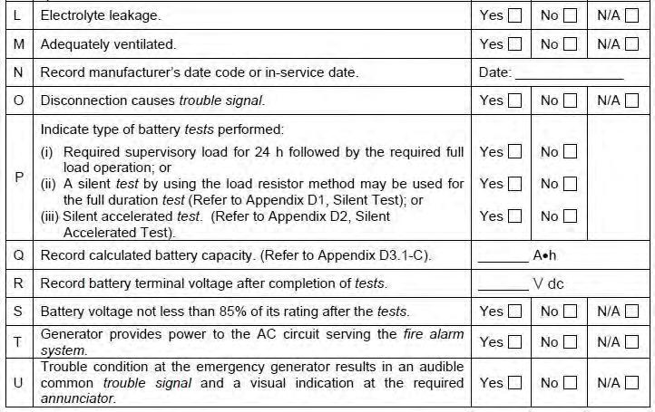
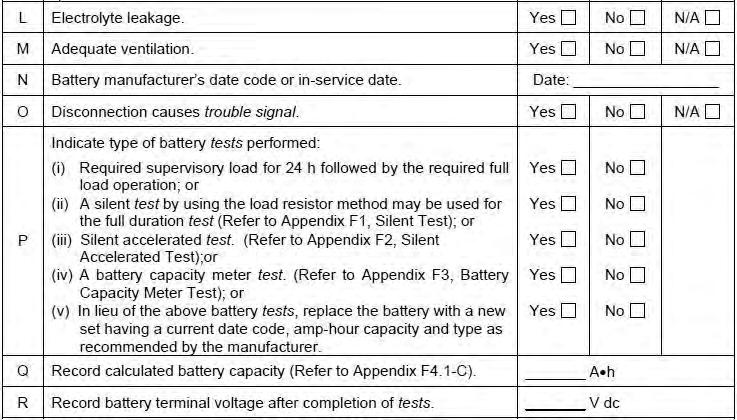
10 F1 SILENT TEST F.1 Selection of resistors for the battery tests should be: A Supervisory Load Resistor: RS = V Ex.: 24v = 24ohms Is 1a and its power rating shall be: Ps IsV Ex.: 1a(24v) = 24watts Where Rs = Supervisory load resistance in OHMS V = Nominal battery terminal voltage, e.g. 24 V Is = Supervisory current measured at battery terminals, AC off B Alarm Load Resistor: Ra = V Ex.: 24v = 8ohms Ia 3a and its power rating shall be: Pa IaV Ex.: 3a(24) = 72 watts where Ra = Alarm load resistance in OHMS V = Nominal battery terminal voltage Ia = Alarm current measured at battery terminals, AC off. 10
11 F2 SILENT ACCELERATED TEST F2.1 The silent accelerated test in this Subsection is intended as an alternate to Subsection F1, Silent Test, for small conventional system in which the service person would be able to complete all of the requirements prescribed in this Standard in 1 d or less. It avoids returning the following day to confirm the end point condition of a 24 h battery test. F2.2 The formula in Clause F2.4 prorates the time that the Alarm Load (Ia) is applied to the battery, based on a combining of Alarm and Supervisory Current multiplied by an acceleration figure. The formula recognizes that the higher discharge rate will reduce the effective amp-hour battery rating. It is based on a 5 min alarm (bell) requirement. F2.3 Large systems with two-stage operation and/or voice communication or with signalling during other than 5 min should follow the tests described in Subsection F1, Silent Test. F2.4 Full load conditions should be applied for a period of time not less than that calculated by the following formula. Battery voltage should not be less than 85% of rating during the test. The duration of the test should be determined as follows: 11
12 Hr = [(IsxD)+(Iax0,5)](1,2) Ex.: [(1ax24h)+(3ax0,5)](1,2) = 10,2Hr Ia 3a Where: Hr = hours D = Required system supervisory time (normally 24 h) Is = Supervisory Current Ia = Alarm Load Current The resistor should be determined as follows: RL (OHMS) = V/Ia PL (WATTS) = V(Ia) Ex.: 24v/3a = 8ohms Ex.: 24v(3a) = 72watts RL should be connected directly across the battery terminals for the time duration determined above. F2.5 As an alternate to the calculation in F2.4, the battery may be discharged in accordance with the battery manufacturer s capacity chart for the specific battery using suitable sized load resistors. 12
13 F3 BATTERY CAPACITY METER TEST F3.1 The capacity should not be less than the calculated A h requirements of the system after the test, otherwise, replace batteries: A Disconnect test battery from system; B Connect the capacity meter across the battery in accordance with the meter manufacturer s instructions; and C Note the capacity of the battery. F4 BATTERY CAPACITY CALCULATION F4.1 Perform battery capacity calculation as follows: A [Supervisory current as per Appendix E2.5 Item D] x [Supervisory Requirement (h)]= A h Ex.: 1Ax24h = 24Ah B [Full load current (A) as per Appendix E2.5 Item E] x [Alarm Requirement (h)] = A h Ex.: 3Ax0,5h = 1.5Ah C System Battery Capacity Requirement A h = (F4.1 Item A result) + (F4.1 Item B result) Enter the result into Appendix E2.5 Item Q of the report. Ex.: 24Ah+1.5Ah = 25.5Ah 13
14 F5 EMERGENCY POWER FOR FIRE ALARM SYSTEMS NBC Emergency Power for Fire Alarm Systems 1) An emergency power supply conforming to Sentences (2), (3) and (4) shall be provided for fire alarm systems. 2) The emergency power supply required by Sentence (1) shall be supplied from a) a generator, b) batteries, or c) a combination thereof. 3) The emergency power supply required by Sentence (1) shall be capable of providing a) supervisory power for not less than 24 h, and b) immediately following, emergency power under full load for not less than i) 2 h for a building within the scope of Subsection , ii) 1 h for a building classified as Group B major occupancy that is not within the scope of Subsection , iii) 5 min for a building not required to be equipped with an annunciator, and iv) 30 min for any other building. 14
15 4) The emergency power supply required by Sentence (1) shall be designed so that there will be automatic transfer to emergency power in the event of a failure of the normal power source. 5) An emergency power supply shall be provided for the voice communication system required by Article ) The emergency power supply required by Sentence (5) for the voice communication system shall be capable of a) full operation immediately upon the failure of the normal source of power, and b) maintaining operation of the system for not less than 2 h. 7) If the emergency power supply required by Sentence (5) is provided by batteries, the batteries shall be sized to provide the total energy consumed by the maximum possible electrical supervision current plus the trouble signal current for a period of 24 h followed by 30 min of continuous voice communication. 15


16 16

17 FACP With AC Power On 17
18 FACP on Supervisory

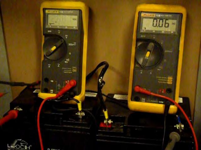
19 Battery Tester

20 Resistor Full Load

21 Battery Recharge


22 22
23 Definitions CAN/ULC-S & CAN/ULC-S GLOSSARY FAULT ISOLATION MODULE A device used in data communication links for wire to wire short circuit protection. CAN/ULC-S GLOSSARY 3.39 FAULT ISOLATOR A device used for wire to wire short circuit protection. 23
24 CAN/ULC-S AUDIO BUSS FAULT ISOLATOR A fault isolator intended for use on audio (paging, telephone or tone) busses to ensure that a short circuit fault on an audio buss in one fire alarm zone does not prevent the normal operation of an audio buss in another fire alarm zone DATA FAULT ISOLATOR A fault isolator intended for use on data communication links to ensure that a short circuit fault on a data communication link in one fire alarm zone does not prevent the normal operation of a data communication link in another fire alarm zone POWER BUSS FAULT ISOLATOR A fault isolator intended for use on power busses to ensure that a short circuit fault on a power buss in one fire alarm zone does not prevent the normal operation of a power buss in another fire alarm zone SUITE FAULT ISOLATOR A fault isolator intended for use on signal circuits serving suites of a residential or care occupancy to ensure that a short circuit fault on a signal circuit in one suite of a residential or care occupancy does not prevent the normal operation of a signal device in another suite of a residential or care occupancy. 24
25 CAN/ULC-S & CAN/ULC-S GLOSSARY 3.29 FAULT ISOLATION MODULE A device used in data communication links for wire-to-wire short circuit fault protection POWER ISOLATION MODULE A device used in a power distribution riser for wire-to-wire short circuit fault protection SUITE ISOLATOR DEVICE A device serving suites of residential occupancies for wire-to-wire short circuit fault protection. 25
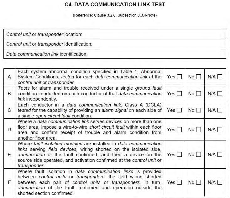
26 Testing Fault Isolation Modules CAN/ULC-S VERIFICATION OF FIRE ALARM SYSTEMS Where fault isolation modules are installed in data communication links serving field devices, wiring shall be shorted on the isolated side, annunciation of the fault confirmed, and then a device on the source side shall be operated, and activation confirmed at the control unit or transponder Where fault isolation in data communication links is provided between control units or transponders, the field wiring shall be shorted between each pair of control units or transponders, in turn, annunciation of the fault confirmed and operation outside the shorted section confirmed. 26
27 27
28 CAN/ULC-S INSPECTION AND TESTING OF FIRE ALARM SYSTEMS Where fault isolation modules are installed in data communication links serving field devices, wiring shall be shorted on the isolated side, annunciation of the fault confirmed, and then a field device on the source side shall be operated, and activation confirmed at the control unit or transponder Where fault isolation in data communication links is provided between control units or transponders and between transponders, introduce a short circuit fault and confirm annunciation of the fault and operation outside the shorted section between each pair of: A Control unit to control unit; B Control unit to transponder; and C Transponder to transponder. 28
29 29
30 30
31 31


32 Smoke Detector Sensitivity Measurement 32
33 CAN/ULC-S INSPECTION AND TESTING OF FIRE ALARM SYSTEMS Smoke Detectors General Each smoke detector shall be visually inspected for cleanliness. When required, cleaning shall be in accordance with the manufacturer s recommendations Each smoke detector shall be tested for operation by introducing smoke or simulated smoke to the detecting chamber in accordance with the manufacturer s instructions Each smoke detector shall be tested to confirm that it is within its rated operating range using a test method described in Clause (Refer to Appendix E3.1, Field Device Testing-Legends and Notes.) A smoke detector whose sensitivity is not within the required operating range shall be cleaned, retested in accordance with Clause , and if still not within its rated sensitivity, replaced with a compatible smoke detector. (Refer to Appendix E3.1, Field Device Testing-Legends and Notes.) 33
34 Each smoke detector sensitivity measurement and if applicable, the cleaning date shall be recorded on the individual device record. (Refer to Appendix E3.1, Field Device Testing-Legends and Notes.) Acceptable methods of determining the smoke detector sensitivity are: A Manufacturer s recommended test instrument, equipment, or method; B Installed control units or transponders designed to test the sensitivity of individual smoke detectors; or C Calibrated instruments that provide the operation as described in CAN/ULC-S529, Standard for Smoke Detectors for Fire Alarm Systems, for the purpose of testing smoke detector sensitivity. 34
35 Documenting Smoke Detector Sensitivity Measurement CAN/ULC-S E3. FIELD DEVICE TESTING LEGEND AND NOTES The following notes apply to Appendix E3.2, Individual Device Record: NOTE 1: Smoke detector sensitivity confirmation or measurement should be recorded in the remarks column. NOTE 2: Smoke detector cleaning or replacement date should also be recorded in the remarks column. 35
36 36


37 SMOKE DETECTOR SENSITIVITY The relative degree of response of a smoke detector expressed in %/foot obscuration. A high sensitivity detector responds to a lower concentration of smoke while a low sensitivity detector responds to a high concentration of smoke under identical fire test conditions. 37
38 NEWER SMOKE DETECTORS Addressable: real time monitoring/diagnostics reporting directly to the fire alarm control panel. Some detectors look for fire signature, not just smoke, can require specialized knowledge to test correctly. Can utilize drift compensation technology Conventional: easier testing with information available. Variety of methods: Obscuration Voltage Diagnostic LED S Can utilize drift compensation technology OLDER SMOKE DETECTORS Conventional: Information may be difficult to source. Specialized testing equipment required. Continued testing with smoke or aerosol over time or incorrectly used may contribute to detectors either becoming more or less sensitive over time. 38
39 WHY? Smoke detectors do drift outside of their listed smoke detector sensitivity range, introducing smoke into the chamber and seeing the detector alarm, does not prove that it is still operating within it s designed parameters and will work in a real fire condition to detect the products of combustion when required! 39
40 Thank you!!!
Building Name: Our Lady of Sorrows Date: July 10, 2013
 1 E1. FIRE ALARM SYSTEM ANNUAL TEST AND INSPECTION REPORT (Reference: 5.1.2) Building Name: Our Lady of Sorrows Date: July 10, 2013 Address 19 Mohns Avenue Petawawa, ON System Manufacturer: Siemens Model
Smoke Detector Testing
 Smoke Detector Testing Allen Hess CFAA Presentation April 2011 1 Building Technologies Agenda Requirements Consumer Needs Challenges with Industry Acceptance How siemens a Detector sans italic Works Effects
CERTIFICATION BULLETIN
 File: ULC-S527-11 ULC-G5.2 June 1, 2012 CERTIFICATION BULLETIN 2012-04 Effective Date Announcement CAN/ULC-S527-11, 3 rd Edition of the Standard for Control Unit for Fire Alarm Systems To: Subscribers
SOME OF THE MOST COMMON TESTING MISTAKES MADE BY TECHNICIANS PERFORMING VERIFICATIONS TO CAN/ULC S537-04
 SOME OF THE MOST COMMON TESTING MISTAKES MADE BY TECHNICIANS PERFORMING VERIFICATIONS TO CAN/ULC S537-04 OR Some of the things that I done have wrong and was told how stupid I was! Why is it hard to make
CAN/ULC-S E1. FIRE ALARM SYSTEM ANNUAL TEST & INSPECTION REPORT (Reference: Clause 5.1.2)
") CAN/ULC-S536-04 E1. FIRE ALARM SYSTEM ANNUAL TEST & INSPECTION REPORT (Reference: Clause 5.1.2) Member YES = Tested Correctly Building Name: Address: Contact: Job Number: System Manufacturer: No = Did
CAN/ULC-S536-04 E1. FIRE ALARM SYSTEM ANNUAL TEST & INSPECTION REPORT (Reference: Clause 5.1.2) Member YES = Tested Correctly Building Name: Address: Contact: Job Number: System Manufacturer: No = Did
Clarification. Summary of Changes. Summary of Changes. Alan Cavers Area Manager Fire & Security Systems Group
 Summary of Changes CAN/ULC-S524-06 Installation of Fire Alarm Systems Alan Cavers Area Manager Fire & Security Systems Group Course Title Rev Date: Summary of Changes Correct Deficiencies noted CAN/ULC-S524-01
UEI-1 UNIVERSAL END-OF-LINE / ISOLATOR TESTER
 UEI1 UNIVERSAL ENDOFLE / ISOLATOR TESTER With Easy Testing Technology STALLATION & OPERATG STRUCTIONS These instructions are provided to ensure compliance with the installation requirements of NFPA72 (National
Fort Rouge Leisure Centre Section HVAC Upgrades Phase 2 Page 1 of 5 Bid Opportunity No March 2013 FIRE ALARM SYSTEMS
 HVAC Upgrades Phase 2 Page 1 of 5 Part 1 General 1.1 SUMMARY.1 Section Includes:.1 Materials and installation for fire alarm systems upgrades..2 Audible signal devices..3 End-of-line devices..4 Sustainable
AL802ULADA. NAC Power Extender. Installation Guide. (See Application Guide for additional information) Rev
 Rev") AL802ULADA NAC Power Extender Installation Guide (See Application Guide for additional information) Rev. 031703 Overview: The Altronix AL802ULADA is an extremely cost effective 8 amp voltage regulated
AL802ULADA NAC Power Extender Installation Guide (See Application Guide for additional information) Rev. 031703 Overview: The Altronix AL802ULADA is an extremely cost effective 8 amp voltage regulated
INSPECTION AND TESTING FORM
 INSPECTION AND TESTING FORM Date: Time: SERVICE ORGANIZATION Name: Address: Representative: License No.: MONITORING ENTITY Contact: Monitoring Account Ref. No.: TYPE TRANSMISSION McCulloh Multiplex Digital
Canadian Fire Alarm Association (CFAA)
") An Overview of Changes in the New CAN/ULC-S524-06 Installation of Fire Alarm Systems Canadian Fire Alarm Association (CFAA) CAN/ULC - S524-01 STANDARD FOR THE INSTALLATION OF FIRE ALARM SYSTEMS Installation
An Overview of Changes in the New CAN/ULC-S524-06 Installation of Fire Alarm Systems Canadian Fire Alarm Association (CFAA) CAN/ULC - S524-01 STANDARD FOR THE INSTALLATION OF FIRE ALARM SYSTEMS Installation
CAN/ULC-S1001, INTEGRATED SYSTEMS TESTING OF FIRE PROTECTION & LIFE SAFETY SYSTEMS Simon Crosby, LEL, CET, CFPS October 21, 2015
 CAN/ULC-S1001, INTEGRATED SYSTEMS TESTING OF FIRE PROTECTION & LIFE SAFETY SYSTEMS Simon Crosby, LEL, CET, CFPS October 21, 2015 Fire Commissioning in Canadian Codes and Standards BACKGROUND Why Commissioning?
30.45 Electric Release PDRP-2001
 The PDRP-2001 Fire Alarm Control Panel (FACP) is a six-zone control panel for single and dual hazard deluge and preaction applications. The FACP is compatible with conventional input devices (2-wire or
CAN/ULC-S INTEGRATED SYSTEMS TESTING OF FIRE PROTECTION AND LIFE SAFETY SYSTEMS
 2013 Randal Brown & Associates Engineering Ltd. 1 RANDAL BROWN & ASSOCIATES ENGINEERING LTD. CONSULTING ENGINEERS LIFE SAFETY & FIRE PROTECTION 105 6 LANSING SQUARE TORONTO, ONTARIO CAN/ULC-S1001-11 INTEGRATED
OWNERS RESPONSIBILITIES & CASE STUDIES ONTARIO FIRE CODE. John Percy, Public Education Officer Waterloo Fire Rescue
 OWNERS RESPONSIBILITIES & CASE STUDIES ONTARIO FIRE CODE John Percy, Public Education Officer Waterloo Fire Rescue AGENDA: Fire Protection and Prevention Act and Ontario Fire Code Role of Assistants to
CAN/ULC S Integrated Systems Testing of Fire Protection and Life Safety Systems and Fire Protection Commissioning
 CAN/ULC S1001-11 Integrated Systems Testing of Fire Protection and Life Safety Systems and Fire Protection Commissioning Presentation To: Canadian Fire Alarm Association (CFAA) National Capital Region
CAN/ULC-S561. To comply, or not to comply. actually it s not even a question! Underwriters Laboratories of Canada. By Alan Cavers & Brian McBain
 CAN/ULC-S561 To comply, or not to comply. actually it s not even a question! By Alan Cavers & Brian McBain CAN/ULC-S561, Installation And Services For Fire Signal Receiving Centres And Systems is without
CAN/ULC-S1001, INTEGRATED SYSTEMS TEST OF FIRE PROTECTION AND LIFE SAFETY SYSTEMS
 RANDAL BROWN & ASSOCIATES ENGINEERING LTD. CONSULTING ENGINEERS LIFE SAFETY & FIRE PROTECTION 105 6 LANSING SQUARE TORONTO, ONTARIO CAN/ULC-S1001, INTEGRATED SYSTEMS TEST OF FIRE PROTECTION AND LIFE SAFETY
PSN-1000 & PSN 1000(E) Installation Manual
 Installation Manual") PSN-1000 & PSN 1000(E) Installation Manual Potter Electric Signal Company, LLC St. Louis, MO Customer Service: (866) 240-1870 Technical Support: (866) 956-1211 Fax: (314) 595-6999 www.pottersignal.com
PSN-1000 & PSN 1000(E) Installation Manual Potter Electric Signal Company, LLC St. Louis, MO Customer Service: (866) 240-1870 Technical Support: (866) 956-1211 Fax: (314) 595-6999 www.pottersignal.com
109-B Concord Drive Casselberry, FL DynaFire.com INSPECTION AND TESTING FORM PER NFPA 72. Owner s Address: Owner's Phone Number:
 109-B Concord Drive Casselberry, FL 32707 407.830.6500 DynaFire.com INSPECTION AND TESTING FORM PER NFPA 72 Pg 1 of 4 Equity One 11180600 Owner/Representative: WO#: _Customer#: 1550 NE Miami Garden Dr
MR-2602 Two Zone Fire Alarm Control Panel
 MR-2602 Two Zone Fire Alarm Control Panel Installation Manual Secutron LT-2015 Rev.3 July 2010 Table of Contents 1 Introduction 1.1 The MR-2602 Fire Alarm Control Unit... 11 1.1.1 General features...
BOMA Calgary Luncheon Thursday, October 11, 2012 Building Owners Responsibilities for Fire Safety Equipment (Fire Alarm) Canadian Fire Alarm
 Canadian Fire Alarm") 1 BOMA Calgary Luncheon Thursday, October 11, 2012 Building Owners Responsibilities for Fire Safety Equipment (Fire Alarm) Canadian Fire Alarm Association 2 Presentation Overview The Codes Your responsibilities
1 BOMA Calgary Luncheon Thursday, October 11, 2012 Building Owners Responsibilities for Fire Safety Equipment (Fire Alarm) Canadian Fire Alarm Association 2 Presentation Overview The Codes Your responsibilities
Scope. Warning sounders except specific requirements. Intercom Systems for Emergency Purposes. Sound Systems for Emergency Purposes
 Scope Section 6 covers all Control and Indicating Equipment including Local Alarm systems. Section 6 also covers all detectors and input/output devices, including Occupant Warning sounders except specific
PROPOSED CHANGE TO THE 2012 BUILDING CODE O. REG. 332/12 AS AMENDED
 Ministry of Municipal Affairs PROPOSED CHANGE TO THE 2012 BUILDING CODE O. REG. 332/12 AS AMENDED CHANGE NUMBER: SOURCE: B-03-02-07 Ontario-NBC CODE REFERENCE: Division B / 3.2.4.22. and 3.2.4.23. DESCRIPTION
ACC-25/50ZST. Zoned System Voice with Telephone Evacuation Control Panel
 ACC-25/50ZST Zoned System Voice with Telephone Evacuation Control Panel General The AUDIO COMMAND CENTER 25/50 Zone System with FireFighters Telephone (ACC-25/50ZST) is a state-of-the-art Emergency Voice
COMMERCIAL (IBC) FIRE ALARM SUBMITTAL GUIDE
 FIRE ALARM SUBMITTAL GUIDE") COMMERCIAL (IBC) FIRE ALARM SUBMITTAL GUIDE SUPERVISION OF AUTOMATIC FIRE SPRINKLER SYSTEMS SUPERVISION OF ALTERNATIVE AUTOMATIC FIRE-EXTINGUISHING SYSTEMS FIRE ALARM AND DETECTION SYSTEMS The Fire Alarm
COMMERCIAL (IBC) FIRE ALARM SUBMITTAL GUIDE SUPERVISION OF AUTOMATIC FIRE SPRINKLER SYSTEMS SUPERVISION OF ALTERNATIVE AUTOMATIC FIRE-EXTINGUISHING SYSTEMS FIRE ALARM AND DETECTION SYSTEMS The Fire Alarm
MAINTENANCE OF FIRE PROTECTION DEVICES WITHIN RESIDENTIAL SUITES OF MULTI-FAMILY BUILDINGS
 FIRE CODE BULLETIN December 2004 97 FCB 018 (R1) Page 1 of 5 BACKGROUND: MAINTENANCE OF FIRE PROTECTION DEVICES WITHIN RESIDENTIAL SUITES OF MULTI-FAMILY BUILDINGS Fire protection service companies are
Fire Alarm System Training
 Fire Alarm System Training Contact us Today for a FREE quotation to deliver this course at your company?s location. https://www.electricityforum.com/onsite-training-rfq Tragic and costly fires, changes
MS-4012/4024 and CMS-4012/4024. Instruction Manual for the. Fire Alarm Control Panels
 R 12 Clintonville Road, Northford, CT 06472 Phone: (203) 484-7161 FAX: (203) 484-7118 Instruction Manual for the MS-4012/4024 and CMS-4012/4024 Fire Alarm Control Panels Document 15586 5/11/93 Revision:
VERIFICATION OF FIRE ALARM SYSTEMS
 DEVELOPMENT, BUILDINGS AND LICENSING Chief Building Official (CBO) and Building Code and Policy Building Policy Branch The intent of this bulletin is to clarify requirements of verification of the fire
Module 9: Ontario Building Code Fire Fighting Provisions
 Ontario Building Code (OBC) 1. Sprinklers 2. Standpipes 3. Fire Alarms 4. Entrances Ontario Building Code (OBC) 1. Sprinklers 2. Standpipes 3. Fire Alarms 4. Entrances 1. Sprinklers i) Sprinkler Systems
Booster Power Supply Manual
 Supply Manual DEVELOPED BY COPYRIGHT NOTICE General Signal Building Systems Corporation 6411 Parkland Drive Sarasota, FL 34243 (941) 739-4300 Copyright 1999 General Signal Building Systems Corporation
Control Panels. Control Panels for Commercial Applications. Control panels provide the central processing
 Control Panels Control Panels for Commercial Applications Control panels provide the central processing and logic for an integrated system. In a typical system, there are four major functions: inputs,
Fire Signal Receiving Centres vs. Proprietary Fire Signal Receiving Centres CAN/ULC-S561 ALAN CAVERS ULC
 Fire Signal Receiving Centres vs. Proprietary Fire Signal Receiving Centres CAN/ULC-S561 ALAN CAVERS ULC Reliable Fire Alarm Monitoring Why is it important? Codes and Standards? What is a fire alarm monitoring?
Functional Performance Test
 Fire Alarm Control Panel & Fire Alarm Annunciator Panel Notify all building occupants that testing will be conducted. Fire alarm contractor shall have personnel with 2-way radios at the fire alarm control
STANDARDS BULLETIN
 June 2, 2008 STANDARDS BULLETIN 2008-08 CAN/ULC-S319-05, Electronic Access Control Systems FREQUENTLY ASKED QUESTIONS The following frequently asked questions (FAQ) is being issued in response to a request
British Columbia Building Code 2006 Division B Part 3 Fire Protection, Occupant Safety and Accessibility Section 3.2 Building Fire Safety
 Div B 3.2.1.1.(4), (5) & (6) Exceptions in Determining Building Height BCBC1998-3.2.1.1.(4), (5) & (7) replace (harmonize with NBC) - NBC 2005 has significant revisions to provisions for mezzanines. These
ECC-50/100C. Emergency Command Center
 ECC-50/100C Emergency Command Center Canadian DF-60815:B Emergency Communications General Fire-lite s ECC-50/100C is a multipurpose emergency voice evacuation panel for fire applications, mass notification
IntelliKnight 5820XL Addressable Fire Alarm Control System Sales Guide
 IntelliKnight 5820XL Addressable Fire Alarm Control System Sales Guide Product Overview The IntelliKnight 5820XL is an intelligent addressable fire alarm control panel designed for flexibility and reliability.
Project No Belleville Fire Hall/Headquarters and Emergency Operations Centre Section Belleville, Ontario Page 1 of 10
 Belleville, Ontario Page 1 of 10 1 GENERAL 1.1 GENERAL REQUIREMENTS.1 The General Conditions of CCDC2-2008, and the General requirements of Division 1, form part of this Section and must read in conjunction
D7050DH. Installation Instructions. Multiplex Photoelectric Duct Smoke Detector
 D700DH EN Installation Instructions Multiplex Photoelectric Duct Smoke Detector D700DH Installation Instructions.0 Description Notices These instructions cover the installation of the D700DH Multiplex
AL802ULADA. NAC Power Extender. Installation Guide. (See Application Guide for additional information)
") AL802ULADA NAC Power Extender Installation Guide (See Application Guide for additional information) Rev. 042010 Agency Listings: UL Listed Control Units for Fire Protective Signaling Systems (UL 864).
AL802ULADA NAC Power Extender Installation Guide (See Application Guide for additional information) Rev. 042010 Agency Listings: UL Listed Control Units for Fire Protective Signaling Systems (UL 864).
AL800ULADA. NAC Power Extender. Installation Guide
 AL800ULADA NAC Power Extender Installation Guide Rev. 122000 AL800ULADA - NAC Power Extender Overview: The Altronix AL800ULADA is an extremely cost effective 8 amp voltage regulated remote power supply/battery
good things in small packages
 FireShield Control Panels good things in small packages life safety for small buildings and shops A perfect arrangement FireShield offers the very best conventional fire alarm technology available, with
Commercial and Light Industrial Fire Alarm Control Panel
 FireSystem 2000 Commercial and Light Industrial Fire Alarm Control Panel Features Easily expandable. All new plug-in board design Two supervised audible circuits Lamp and system trouble circuit test Ground
- 4 12VDC or 24VDC VDC or 24VDC - Eight (8) Fused Outputs - Eight (8) PTC Outputs. Installing Company: Service Rep.
 Fused Outputs - Eight (8) PTC Outputs. Installing Company: Service Rep.") 140 58th St. Brooklyn, NY Power Supply/Chargers Installation Guide Models Include: eflow4n/eflow4nx - 4 amp @ 12VDC or 24VDC eflow4n8/eflow4nx8 eflow4n8d/eflow4nx8d - 4 amp @ 12VDC or 24VDC - 4 amp @ 12VDC
140 58th St. Brooklyn, NY Power Supply/Chargers Installation Guide Models Include: eflow4n/eflow4nx - 4 amp @ 12VDC or 24VDC eflow4n8/eflow4nx8 eflow4n8d/eflow4nx8d - 4 amp @ 12VDC or 24VDC - 4 amp @ 12VDC
Fire Alarm Testing and Inspection Report
 Fire Alarm Testing and Inspection Report Property Name: Property Address: Property Manager: Contact: Phone Number: Central Station: Phone Number: PELICAN ISLE II 35 DOCKSIDE RD. NAPLES, FLORIDA 3110 BILL
A Building Manager s Guide to Maintaining Fire Code Compliance
 A Building Manager s Guide to Maintaining Fire Code Compliance Know your role in conducting fire protection system inspections : Fire Alarm Codes and Standards Maintaining your compliance with fire code
SHORT CIRCUIT ISOLATOR TO NEXT COMPONENT REQUIRING POWER TO NEXT KEYPAD (** IF REQUIRED) STROBE RELAY MODULE KEYSWITCH ISOLATION MODULE STROBE
 STROBE RELAY MODULE KEYSWITCH ISOLATION MODULE STROBE") The Door Switch 11772 Westline Industrial Drive St. Louis, Mo 63146 (877) 998-5625 www.thedoorswitch.com Patent No. RE42,991 and RE44,039 CONTROL PANEL TRANSFORMER (SUPPLIED WITH CONTROL PANEL) NOTIFICATION
The Door Switch 11772 Westline Industrial Drive St. Louis, Mo 63146 (877) 998-5625 www.thedoorswitch.com Patent No. RE42,991 and RE44,039 CONTROL PANEL TRANSFORMER (SUPPLIED WITH CONTROL PANEL) NOTIFICATION
Installation Guide for AL400ULM. Multi-Output Access Control Power Supply Charger
 Installation Guide for AL400ULM Multi-Output Access Control Power Supply Charger R AL400ULM - Multi-Output Access Control Power Supply/Charger Rev. 072500 Overview: The AL400ULM multi-output access control
TrueAlert Addressable Notification Appliances
 UL, ULC Approved* TrueAlert Addressable Notification Appliances Audible Notification Appliances; Multi-Tone Horns with 520 Hz Output Features Individually addressed and controlled TrueAlert ES multi-tone
AL600ULADA. NAC Power Extender. Installation Guide
 AL600ULADA NAC Power Extender Installation Guide Rev. 122000 AL600ULADA - NAC Power Extender Overview: The Altronix AL600ULADA is an extremely cost effective 6.5 amp voltage regulated remote power supply/battery
Unified Fire Authority - Fire Prevention Bureau
 Unified Fire Authority - Fire Prevention Bureau FIRE ALARM AND EMERGENCY COMMUNICATION SYSTEM RECORD OF COMPLETION To be completed by the system installation contractor at the time of system acceptance
AL1002ULADA. NAC Power Extender. Installation Guide. (See Application Guide for additional information) Rev X
 Rev X") AL1002ULADA NAC Power Extender Installation Guide (See Application Guide for additional information) Rev. 071508X Agency Listings: UL Listed Control Units for Fire Protective Signaling Systems (UL 864).
AL1002ULADA NAC Power Extender Installation Guide (See Application Guide for additional information) Rev. 071508X Agency Listings: UL Listed Control Units for Fire Protective Signaling Systems (UL 864).
Fire Alarm System Fundamentals
 Fire Alarm System Fundamentals Mircom is the largest and oldest privately owned fire alarm and life safety manufacturer in North America and 5th largest overall with 50 years of industry experience. Mircom
Annexure - 1. Detectors: Fire Alarm Control Panel :
 Item 1. Supply Part This Specification includes Supply, Warranty, Installation, Testing and Commissioning and integration of the Fire Alarm System mainly consisting of the Fire Alarm Control Panel (FACP),
TECHNICAL DATA. Humidity: 85% Relative Humidity (non-condensing) at 90 F (32 C) maximum.
 at 90 F (32 C) maximum.") September 29, 1997 Firecycle III 433 a 1. PRODUCT NAME VIKING Model E-1 Manufactured 1997 Present 2. MANUFACTURED FOR THE VIKING CORPORATION 210 N Industrial Park Road Hastings, Michigan 49058, U.S.A.
September 29, 1997 Firecycle III 433 a 1. PRODUCT NAME VIKING Model E-1 Manufactured 1997 Present 2. MANUFACTURED FOR THE VIKING CORPORATION 210 N Industrial Park Road Hastings, Michigan 49058, U.S.A.
Multi-Application Peripherals and Accessories
 ON UL, ULC Listed FM Approved MultiApplication Peripherals and Accessories Communicating Devices Communications Individually Addressable Devices FEATURES Individually addressable communications over a
Installation Guide for AL300ULM. Multi-Output Access Control Power Supply Charger
 Installation Guide for AL300ULM Multi-Output Access Control Power Supply Charger R AL300ULM - Multi-Output Access Control Power Supply/Charger Overview: The AL300ULM multi-output access control power supply/charger
DIVISION 26 ELECTRICAL SECTION FIRE ALARM SYSTEM
 DIVISION 26 ELECTRICAL SECTION 26 81 11 PART 1 GENERAL 1.01 DESCRIPTION A. Furnish and install all equipment and accessories for a complete local, analog addressable, manually and automatically actuated,
MODEL B2 INSTALLATION MANUAL
 RELEASE DEVICES GENERAL DESCRIPTION MODEL B2 INSTALLATION MANUAL S/N: The B2 Series Time Delay Release Devices are UL Listed, Canadian Listed, and CSFM Listed for use on rolling doors, single-slide and
Intelligent Single Loop Fire Alarm Control Panel
 Intelligent Single Loop Fire Alarm Control Panel The CAX-CTL-1L Intelligent Single Loop Fire Alarm Control Panel is a member of the industry leading Axis AX Series Intelligent Fre Alarm Control Panels
Installation Guide for models:
 140 58th St. Brooklyn, NY Access Power Controllers with Power Supplies Installation Guide for models: Maximal3FD - 12VDC @ 4.6 amp or 24VDC @ 5.2 amp. - Sixteen (16) PTC protected power-limited outputs.
RELEASE DEVICE CONTROLS
 RELEASE DEVICE CONTROLS RELEASE DEVICE MODEL C+ INSTALLATION MANUAL UL LISTED CANADIAN LISTED CSFM: 7300-48:00 GENERAL DESCRIPTION: MADE IN THE U.S.A. S/N: The LM0-C+ Release Device/Control Panel is a
Type of Fire Alarm Control Panel: System is: Existing OR New If new, provide Electrical Permit Number:
 DATE OF SUBMISSION TO: Department of Licenses and Inspections Commercial and Industrial Fire Inspection Unit 990 Spring Garden Street, 3 rd Floor, Philadelphia, PA 19123 AP# CITY OF PHILADELPHIA FIRE ALARM
Full Service Central Station Fire Alarm Listing Evaluation
 Full Service Central Station Fire Alarm Listing Evaluation Listing Evaluation A UL Listing project includes: 1. Evaluating the central station facility for compliance with UL 827, Central-Station Alarm
Installation Guide for models:
 140 58th St. Brooklyn, NY Access Power Controllers with Power Supplies Installation Guide for models: Maximal11F - Power Supply 1: 12VDC @ 3.3 amp or 24VDC @ 3.6 amp. - Power Supply 2: 12VDC @ 3.3 amp
SECTION FIRE ALARM SYSTEMS
 SECTION 16721 FIRE ALARM SYSTEMS PART 1 - GENERAL 1.01 RELATED DOCUMENTS A. The general provisions of the contract including General and Special Conditions and General Requirements shall apply to all work
Smoke Detector Activation of any smoke detector shall start the alarm verification mode.
 Description: The purpose of the section is to provide the UMCP Design Standards for the design and implementation of Fire Alarm Systems at the UMCP campus. Related Sections: TBD Effective Date: July 10,
TECHNICAL DATA. multi-hazard. model vfr400. Release Control Panel 290a. January 16, 2014
 January 16, 2014 Release Control Panel 290a 1. Description The Viking VFR400 is a microprocessor based releasing control panel for use on preaction, deluge, Surefire, Firecycle multicycle sprinkler systems,
TABLE OF CONTENTS Part 6 Legal Basis for Fire Safety Planning... 2
 TABLE OF CONTENTS Part 6 Legal Basis for Fire Safety Planning... 2 6.1] GENERAL... 2 6.2] EXCERPTS FROM 2012 BC FIRE CODE PART 2 BUILDING AND OCCUPANT FIRE SAFETY... 3 6.3] EXCERPTS FROM 2012 BC FIRE CODE
FireNET Plus Wiring Instructions
 FireNET Plus Wiring Instructions This manual provides wiring instructions for the 1 loop and 2 loop version of the FireNET Plus panels, which supports our finest Hochiki s DCP protocol. Note: Refer to
TrueAlert Addressable Notification Appliances
 UL, ULC Listed* TrueAlert Addressable Notification Appliances Audible/Visible Notification Appliances; Multi-Tone Horn/Strobe with 520 Hz Output Features Individually addressed and controlled multi-tone
SIGA-CC1 Single Input Signal Module Installation Sheet
 SIGA-CC1 Single Input Signal Module Installation Sheet Personality codes Use the personality codes described below to configure the SIGA-CC1 module. See Table 1 for listing information Table 1: Personality
Data Sheet Fire Safety & Security Products. System Overview. Initiating Circuits SXL-EX FACP 7906
 s Data Sheet Fire Safety & Security Products SXL-EX Fire Alarm Control Panel Conventional Zone Fire Alarm Control Panel ARCHITECT AND ENGINEER SPECIFICATIONS Four (4) zones expandable to eight (8) zones
Fire - Rescue. November 2016
 Fire - Rescue Fire Alarm and Central Station Monitoring Plan Submittal Guidelines November 2016 Plan Submittal Guidelines are provided based on the 2015 International Fire Code, Policies, and Local Amendments.
FireSystem 2000 Commercial and Light Industrial Fire Alarm Control Panel
 PROTECTOWIRE FireSystems Features Easily expandable Two supervised audible circuits Lamp and system trouble circuit test Ground fault detection Initiating device circuit (IDC) alarm test Monitors up to
Signature Series Auto-Sync Output Module (CC1S)
") Signature Series Auto-Sync Output Module (CC1S) Product description Mounting The Signature Series can be mounted in a North American 2-1/2 in (64 mm) deep 2-gang box or a standard 4 in square box 1-1/2
Signature Series Auto-Sync Output Module (CC1S) Product description Mounting The Signature Series can be mounted in a North American 2-1/2 in (64 mm) deep 2-gang box or a standard 4 in square box 1-1/2
Automatic Fire Alarm Association Webinar On Inspection, Testing, And Maintenance Of Fire Alarm Systems
 Automatic Fire Alarm Association Webinar On Inspection, Testing, And Maintenance Of Fire Alarm Systems Your Presenter: Merton Bunker, PE Inspections and tests are intended to reduce or limit: Loss of life
Open-area Smoke Imaging Detector. Engineering Specification
 Open-area Smoke Imaging Detector 15273_02 October 2011 Table of Contents 1. Scope... 3 2. System Information... 3 2.1 General... 3 2.2 Approvals... 3 2.3 Codes, Standards or Regulations... 3 2.4 System
June 10, 2002 DF C S2424
 GENERAL www.firelite.com The Fire Lite FIRE COMMAND 25/50X is a state-of-theart Emergency Voice Evacuation Control Panel (VECP), with significant technological enhancements that set it apart from other
E3 Series Broadband System
 Broadband System Description The, Broadband System includes the NetSOLO Broadband System. Like the Net- SOLO Broadband System, the Broadband is of modular design and allows a wide range of configurations
Installation Manual CFP-105. Fire Alarm Control Panel. Version 1.0
 CFP-105 Fire Alarm Control Panel Installation Manual Version 1.0 WARNING: This manual contains information on limitations regarding product use and function and information on the limitations as to liability
Addressable Fire Alarm Control Panel
 PRODUCT SPECIFICATION XR2400F Addressable FACP Addressable Fire Alarm Control Panel Description The DMP XR2400F Addressable Fire Alarm Control Panel is an expandable Fire Alarm Control with built-in DACT
TECHNICAL DATA OBSOLETE
 Deluge Devices 270a 1. PRODUCT NAME VIKING PAR-3 Available since 1991 2. MANUFACTURED FOR: THE VIKING CORPORATION 210 N. Industrial Park Road Hastings, Michigan 49058 U.S.A. Telephone: (269) 945-9501 (877)
ACSI Series 1550K-MD and 1550-MD Motor Drive Electric Latch Retraction
 ACSI Series 1550K-MD and 1550-MD Motor Drive Electric Latch Retraction Riser and Point-to-Point Drawings for Standard Access Control Applications Using Maintained Latch Retraction Control or Momentary
Chubb Monitoring Solutions
 Chubb Monitoring Solutions A fire or security system is only as effective as the response that it initiates. A comprehensive security / life safety solution must include effective alarm monitoring. It
E3 Series Broadband. Description. Features. Intelligent, Networked, Multi-Channel Fire Alarm Control and Emergency Voice Evacuation System
 Broadband Description Intelligent, Networked, Multi-Channel Fire Alarm Control and Emergency Voice Evacuation System The Broadband System includes the Net- SOLO Broadband System. Like the NetSOLO Broadband
2012 OBC Changes. Summary of key changes to Life Safety and Fire Protection Systems for CFAA January 22, 2014
 2012 OBC Changes Summary of key changes to Life Safety and Fire Protection Systems for CFAA January 22, 2014 2012 OBC New Sentence 3.2.4.2(6) Buildings interconnected by walkways permitted in Articles
E3 Series Broadband System
 Voice Evacuation E3 Series Broadband System Intelligent, Networked, Multi-Channel Fire Alarm Control and Emergency Voice Evacuation System General The, E3 Series Broadband System is a modular design and
COURSE SYLLABUS FIRE ALARM AND FIRE SUPPRESSION SYSTEMS CORRESPONDENCE COURSE
 COURSE SYLLABUS FIRE ALARM AND FIRE SUPPRESSION SYSTEMS CORRESPONDENCE COURSE 100130 Description The first part of the course presents the requirements for fire alarm systems. It describes the buildings
AL1042ULADA. NAC Power Extender. Installation Guide. (See Application Guide for additional information) Rev X
 Rev X") AL1042ULADA NAC Power Extender Installation Guide (See Application Guide for additional information) Rev. 071508X Agency Listings: UL Listed for Control Units for Fire Protective Signaling Systems (UL
AL1042ULADA NAC Power Extender Installation Guide (See Application Guide for additional information) Rev. 071508X Agency Listings: UL Listed for Control Units for Fire Protective Signaling Systems (UL
Installation Guide for AL800UL-ADA. NAC Power Extender. Rev
 Installation Guide for AL800UL-ADA NAC Power Extender Rev. 090500 Overview: The Altronix AL800UL-ADA is an extremely cost effective 8 amps voltage regulated remote power supply /battery charger. The AL800UL-ADA
ERS-3600B. PERS-3600B Personal Emergency Reporting System
 PERS-3600B Personal Emergency Reporting System ERS-3600B A Complete Emergency System For Comprehensive Care The Linear PERS-3600B includes a built-in speakerphone and reminder message capability, providing
CONTENTS Introduction and Characteristics. 1 Fire Alarm System Assembly Diagram.. 2 Fire Alarm Signal Flow Chart.. 2 Panel Descriptions 3 Standard
 CONTENTS Introduction and Characteristics. 1 Fire Alarm System Assembly Diagram.. 2 Fire Alarm Signal Flow Chart.. 2 Panel Descriptions 3 Standard Detector Wiring Method. 4 Method of Wiring.. 5 Wiring
FIRE ALARM SYSTEM 1.1 GENERAL REQUIREMENTS
 VALOUR COMMUNITY CENTRE FIRE ALARM SYSTEM Section 28 00 00 GYMNASIUM ADDITION & RENOVATION Page 1 of 3 28 00 00 FIRE ALARM SYSTEM 1.1 GENERAL REQUIREMENTS 1.2 SCOPE 1. The specification covering the General
Rancho Cucamonga Fire Protection District Prevention Bureau Standard
 Rancho Cucamonga Fire Protection District Prevention Bureau Standard Title: Fire Alarm and Monitoring Systems Standard # 9-3 Effective: May 2002 Number of Pages: 7 Updated: December 2016 for consistency
3.1 Introduction. 3.1 Introduction
 DEPARTMENT OF ARCHITECTURE ABUBAKAR TAFAWA BALEWA UNIVERSITY, BAUCHI ARC 624: ADVANCED BUILDING SERVICES LESSON 3: FIRE DETECTION AND ALARM SYSTEMS IN BUILDINGS 3.1 Introduction 3.1 Introduction 3.2 Conventional
Model 17A00 Expansion Enclosure
 HOME AUTOMATION, INC. Model 17A00 Expansion Enclosure Installation Manual Document Number 17I00-1 Rev A March, 2002 Home Automation, Inc. Model 17A00 Expansion Enclosure Installation Manual Document Number
FMR Installation Instructions. Addressable Fire System Controller
 FMR-7033 EN Installation Instructions Addressable Fire System Controller EN 2 FMR-7033 Installation Instructions Contents Contents Contents...2 1.0 Introduction...3 2.0 Description...3 3.0 Device Mounting...3