1372SA. Large Format Vacuum Forming Machine. Installation, Operating and Service Manual
|
|
|
- Rosamund Morgan
- 5 years ago
- Views:
Transcription


1 Large Format Vacuum Forming Machine. 1372SA Installation, Operating and Service Manual For Parts, Service & Technical Assistance Telephone: +44 (0) Fax: +44 (0)
2 Table Of Content Safety 4 Introduction 8 General arrangement 9 Specifications 10 Foreword 10 Specifications 10 Noise emissions 10 Machine storage 10 Machine transportation, lifting and moving 10 Installation 11 Electrical connection V Three phase supply 11 Phase Connections / Motor Rotation 11 Pneumatic connection 12 Assembly of the control POD 12 Counterbalance arms and weights 12 Cooling System 13 Using the Cooling System 13 Introduction 14 Operation - Main Menu Functions 15 Powering up 15 Main screen controls 15 Operation - Manual Functions 16 Getting started 16 Manual Control Functions 16 Emergency Stop 16 Table buttons (on front machine panel) 17 Manual Clamping 17 Control POD Manual operation Screen 18 Manual Setup 20 Operation - Setup functions for semi automatic use 21 Operation - Semi-automatic cycle 30 Heater Settings SA - Zone Layout SA Heater element power arrangement 31 Heating Zone Control and Adjustment 31 2
3 Table Of Content (continuation) Other Controls and user adjustments 32 Table Speed adjustment 32 Table Height Adjustment 33 Clamp Frame rear spring adjustment 33 Clamp Frame speed adjustment 33 Front clamp limit switch adjustment 34 Clamp frame Jacking bars - Front and Rear 34 Counterweight adjustment - loading and unloading 34 Touch screen control POD position 34 Heater motor speed 34 Fixing mould tools 35 Fault diagnostics/maintenance 36 Electrical 36 Typical fault scenarios 36 Heater 37 Replacing a heating element 37 Auto-Levelling system 38 Vacuum 39 Vacuum system 39 Pneumatics 40 Table Cylinder Maintenance 41 General lubrication 41 Clamp & Table Seals 41 To replace a damaged or worn seal 41 Cleaning 42 Lubrication 42 Panel Seals 42 Service Support 42 Forming Difficulties 43 Warranty 44 Clamp Seals 44 Heating elements 44 Vacuum system 44 Electrical Circuit information 45 EC Certificate 55 3
4 Safety Thank you for choosing Formech. Please read and follow the below safety instructions before attempting to install or operate your machine. Special attention should be paid to sections dealing with safety. It is impossible to cover all aspects of thermoforming within the scope of this manual, we are therefore available to offer advice on special problems regarding thermoforming techniques, tooling and materials. 1) The electrical supply to the machine must be of adequate capacity. Wiring must be to local regulations and carried out by a suitably qualified technician. THIS MACHINE MUST BE EARTHED IN ACCORDANCE WITH LOCAL REGULATIONS. 2) Ensure that the pneumatic air supply is regulated to 6 BAR or less and is properly filtered & lubricated using a good quality airline oil. A competent person must make compressed air connections. 3) Do not operate the machine until you have been trained and are fully conversant with it. Read and understand all of this User Manual. Users of this machine should complete regular competence tests. 4) Never remove any panels unless both the electrical and pneumatic supplies have been isolated. Never remove any warning labels from the machine. It is important to understand that high pressures may be present within parts of the pneumatic system even after the supply has been isolated. Special care must be taken if any parts have become jammed to ensure that all pressure is removed before attempting a repair. 5) Daily repetitive use of this or any other machine may lead to a) fatigue and loss of concentration. b) possible strains. Operators should be trained in the use of correct lifting techniques in order to minimise these effects. 6) When servicing the machine care must be taken to prop any heavy moving parts. This refers particularly to the mould table, clamping frame and counter balance weights. Always restrict movement of these parts before entering any part of the machine to prevent possible injury. 7) Always let the machine cool down before attempting to work on it. Some parts of the heater and heat shield become extremely hot during operation. 8) Only use the machine for vacuum forming and blow moulding of plastic. It is not intended for any other purpose. 9) Ensure that the area you are working in is properly ventilated and that you are aware of the potential hazards from the plastics you are forming. 10) Ensure that the area surrounding the machine is clean and frequently cleared of finished product and any waste. 11) This machine is fitted with a dry running vacuum pump. Do not lubricate. Do not allow any liquid to enter the vacuum system. Severe damage may be caused if the above is not observed. 4
5 Safety HEALTH & SAFETY - Hazards specific to this machine. It is vital that any person using this machine and the person(s) responsible for the health & safety is made fully aware of the potential hazards that could arise from the use and misuse. These can be broadly categorised as: - 1. Electric Shock. This machine uses Voltages up to 415V. NEVER ATTEMPT ANY REPAIR UNLESS THE ELECTRICAL SUPPLY HAS BEEN LOCKED IN THE OFF POSITION. ONLY SWITCH ON WHEN ALL COVERS & GUARDS HAVE BEEN REPLACED. ONLY A QUALIFIED ELECTRICAL TECHNICIAN MAY WORK ON ANY PARTS CARRYING MAINS VOLTAGE AND SHOULD BE RESPONSIBLE FOR ENSURING THAT THE MACHINE IS IN A SAFE CONDITION BEFORE ALLOWING SERVICES TO BE RESTORED. 2. Burning. Parts of this machine reach temperatures in excess of 300 C over large areas. WAIT UNTIL THE MACHINE HAS COOLED DOWN BEFORE SERVICE WORK COMMENCES. SPECIAL PRECAUTIONS MUST BE TAKEN TO ENSURE THAT ONLY THE MACHINE OPERATOR IS IN THE OPERATING AREA DURING USE. USE PERSONAL PROTECTIVE EQUIPMENT SUCH AS GLOVES WHEN TESTING THE HEATED PLASTIC, HANDLING HOT VACUUM FORMED PARTS, MANUALLY ASSISTING THE FORMING PROCESSS AND TOUCHING HOT SURFACES. INFRARED RADIATION IS EMITTED BY THE QUARTZ HEATERS, ENSURE THAT ANY EXPOSURE TO THIS TYPE OF RADIATION IS SHORT OR COMPLETELY AVOIDED. 3. Injury from Compressed Air. Pressures up to 100 PSI will be present in large volumes on this machine. BE EXTRA CAUTIOUS WHEN DEALING WITH COMPRESSED AIR EVEN AFTER THE MAIN SUPPLY HAS BEEN SHUT OFF DANGEROUS RESIDUAL PRESSURE MAY STILL BE PRESENT WITHIN THE SYSTEM. 4. Toxic Fume Inhalation. When large sheets of plastic are heated fumes will be given off. ENSURE THAT THE MACHINE IS POSITIONED IN AN ADEQUATELY VENTILATED PLACE. ASSESS THE RISKS OF THE MATERIALS TO BE FORMED PRIOR TO USE. 5. Injury from Moving Parts. Where pneumatics components are used to power moving parts there is a risk of personal injury. NEVER REMOVE ANY PANEL OR ATTEMPT ANY REPAIR UNLESS THE COMPRESSED AIR SUPPLY AND THE ELECTRIC SUPPLY HAS BEEN DISCONNECTED. BE EXTRA CAUTIOUS WHEN DEALING WITH COMPRESSED AIR. EVEN AFTER MAIN SUPPLY HAS BEEN SHUT OFF DANGEROUS RESIDUAL PRESSURE MAY STILL BE PRESENT WITHIN THE SYSTEM. NEVER ATTEMPT TO OVERIDE ANY CONTROL SYSTEM INTERLOCK OR SAFETY RELATED CONTROL SYSTEM SUCH AS THE 2 HANDED CONTROL SYSTEM. 5
6 Safety HEALTH & SAFETY - Hazards specific to this machine. 6. Injury from Trapping. There is a risk of trapping fingers and hands when loading mould tools. Ensure appropriate care is taken to prevent trapping and use suitable personal protection. Care is required when operating the clamping frame to ensure that fingers or hands are not trapped. Keep hands clear of the heater rails when pulling the heater forwards. 7. Lifting, Reaching and Stretching. TAKE CARE WITH LIFTING REACHING AND STRETCHING WHEN PERFORMING THE FOLLOWING ACTIVITIES: -Operating the manual heater, the loading of materials and unloading of plastic formings. -Applying manual assistance to formings during vacuum. -Drilling holes and trimming of mouldings on the machine after forming. -The fitting and loading of mould tools. -Loading and fitting of reducing plates and frames. -Fitting and adjustment of Fans. -Replacement and maintenance of top frame and table seals. ENSURE THAT LOCAL LIFTING AND HANDLING PROCEDURES ARE APPLIED AND MONITORED BY A PERSON RESPONSIBLE FOR HEALTH AND SAFETY. 8. Fire. The sheet auto-levelling system allows the level of heated plastic to be kept constant. There is a risk that failure of the level sensors due to misuse of heaters OR the setting of the compressed air supply to a level that exceeds the operating pressure of pneumatics valve and the machine specification may cause the plastic to be blown into the heaters and to be ignited. Periodically monitor and check the condition of the infrared beam sensors. ENSURE THE COMPRESSED AIR SUPPLY IS SET TO THE RECOMMENDED LEVEL AND ONLY USE THE HEATER FOR THE HEATING OF VACUUM FORMING PLASTIC MATERIALS. RISK OF FIRE AS A RESULT OF HEAT AND PLASTICS PRESENTS AN EMERGENCY SITUATION. ENSURE FIRE SAFETY TRAINING IS PERFORMED & CONTROLLED. IT IS ESSENTIAL TO HAVE FIREFIGHTING EQUIPMENT AVAILABLE AT OR NEAR THE MACHINE. USE DRY POWDER (BLUE) OR CARBON DIOXIDE (BLACK) FIRE EXTINGUISHERS. 9. Airborne Particles. Particles present in the working area may become airborne during the use of the fan cooling system, when using an airline to blow onto plastics and when the release function is operated without tooling fitted. ENSURE THAT THE DUST, PARTICLES AND DEBRIS IN THE WORKING AREA ARE KEPT TO A MINIMUM. ENSURE THAT SUITABLE EYE PROTECTION IS WORN. 10. Working at Height. When installing the fan cooling system, it is necessary to work at an appropriate height. Ensure that adequate safety precautions are taken to prevent falling from height and that suitable, stable and secure equipment is used to support your weight when working at height. Ensure that you DO NOT work on your own when working at height. ENSURE THAT LOCAL LIFTING HANDLING AND HIGH LEVEL WORKING PROCEDURES ARE APPLIED AND MONITORED BY A PERSON RESPONSIBLE FOR HEALTH AND SAFETY. 6
7 Safety HEALTH & SAFETY - Hazards specific to this machine. 11. Prohibited Uses DO NOT USE THIS MACHINE FOR ANY PURPOSES OTHER THAN THE VACUUM FORMING AND BLOW MOULDING OF PLASTICS SHEET. DO NOT USE THE HEATER TO APPLY HEAT TO ANY MATERIAL OTHER THAN PLASTIC SHEET AS PART OF THE VACUUM FORMING PROCESS SUCH AS: FOOD PRODUCTS, ALL TYPES OF PARTICLES, POWDER, DUST, ALL TYPES OF LIQUID, WOOD, PAPER, METALS AND ANY FORMS OF COMBUSTABLE MATERIALS. DO NOT USE THE TABLE MECHANISM TO CLAMP, COMPRESS, FOLD OR APPLY FORCE TO ANY ITEM UNDER ANY CIRCUMSTANCES. DO NOT USE THE CLAMPING FRAME TO CLAMP COMPRESS, FOLD OR APPLY FORCE TO ANY ITEM OTHER THAN THE CLAMPING OF SHEET PLASTICS AS PART OF THE VACUUM FORMING PROCESS. DO NOT USE THE RELEASE TABLE AIR FUNCTION TO APPLY PRESSURE FOR ANY OTHER MEANS OTHER THAN TO RELEASE THE MOULDING FROM A FITTED MOULD TOOL. DO NOT USE THE TABLE VACUUM PORT TO SUPPLY VACUUM FOR ANY OTHER MEANS OTHER THAN TO APPLY VACUUM UNDER A MOULD TOOL AS PART OF THE VACUUM FORMING PROCESS DO NOT ALLOW OTHER PERSONS WITHIN 1 METRE (39 INCHES) OF THE TABLE / APERTURE TRAP POINT WHEN OPERATING THE TABLE USING THE TWO HANDED CONTROL TABLE LIFT FUNCTION. DO NOT BLOCK THE PUMP EXHAUST PORT ON THE REAR OF THE MACHINE AND DO NOT USE THIS PRESSURE OUTLET TO APPLY PRESSURE FOR ANY OTHER PURPOSE. DO NOT USE THE TOP OF THE HEATER OR TOP OF THE HEATER GUARD TO STACK PLASTICS OR OTHER MATERIALS. DO NOT USE THE UNDERSIDE OF THE REAR OF THE MACHINE TO STORE ANY ITEM(S). DO NOT USE THE MACHINE TO STACK OR LEAN ITEMS AGAINST THE SIDES. DO NOT USE THE FAN OUTPUTS TO APPLY AIRFLOW FOR ANY OTHER PURPOSE OTHER THAN THE COOLING OF VACUUM FORMINGS AS PART OF THE VACUUM FORMING OR BLOW MOULDING PROCESS. DO NOT OBSTRUCT THE HEATER TRANSORT WITH ANY ITEM OR USE THE TRANSPORT WHEELS TO CUT OR FORM ANY ITEM OR MATERIAL. DO NOT USE ANY OTHER PART OF THE HEATER TO MOVE THE HEATER FORWARDS AND BACKWARDS OTHER THAN THE HEATER HANDLE. DO NOT USE THE FAN GANTRY TO HANG ANY ITEM. DO NOT MOUNT THE FAN POSTS ON THE UNDER SIDE OF THE FAN GANTRY DO NOT REMOVE THE SIDE PANELS OF THIS MACHINE TO USE THE PNEUMATIC CYLINDER TO CUT, COMPRESS, BEND OR FORM ANY ITEM. DO NOT USE OR MODIFY THE ELECTRICAL POWER IN THE CONTROL PANEL TO SUPPLY ANY OTHER DEVICE OR TO APPLY MODIFICATIONS TO THE MACHINE OR ITS FUNCTIONS. THIS IS NOT AN EXHAUSTIVE LIST OF THE POSSIBLE MISSUSE OF THIS MACHINERY. THIS LIST IS WHAT IS CONSIDERED TO BE FORESEEABLE MISSUSE. THE USE OF THIS MACHINE MUST BE ASSESSED, MONITORED AND CONTROLLED BY THE PERSON RESPONSIBLE FOR THE HEALTH AND SAFTEY IN THE ORGANISATION THAT OWNS AND OPERATES THIS MACHINE. 7
8 Introduction The Formech 1372SA is a highly versatile, manually operated Vacuum Forming Machine that will produce high definition mouldings in up to 6mm thick material. It is intended for use only for the Vacuum forming of plastics components and for the blow moulding of heated plastics. The Formech 1372SA incorporates the following features: Easy to use graphical touch screen with single screen forming cycle operation and 20 job storage facility. Powerful quartz heaters PLC controlled in 15 heating zones. Flexible semi-automatic operation. Heater power level standby feature allowing energy saving when heater is in rear position. Heater safety shutoff after idle period A powerful filtered dry rotary vane vacuum pump. Reliable and robust PLC control system & touch screen. Vacuum & Pressure gauge indication. The machine is fitted with an auto-level facility, which detects a droop in the sheet of plastic resulting from softening during its heat cycle. Air is blown into the chamber beneath the plastic keeping the sheet level until it is ready to be formed. A powerful compressed air blow pre-stretch facility. A pneumatically powered scissor table incorporating 2 handed manual control allowing easy and safe use of heavy moulds. Table speed can be adjusted by externally mounted table speed controls. An easily adjustable table height facility to assist performance with shallow mouldings. A powerful compressed air blow facility to release the moulding from the tool. The 1372 is ideal for prototype development work whilst also quite capable of small and large production runs. The machine has been designed to be highly adaptable and functions such as changing a mould, or fitting reducing windows (which allow smaller sheets to be used) can be carried out in the minimum amount of time. Optional powerful fan cooling system. This manual is the original user instructions for the Formech It informs the user on machine safety, assembly, operation and maintenance. It also provides an introduction into vacuum forming with some useful advice on mould making and post forming processes. If you would like a more comprehensive guide to the vacuum forming process then please visit the support and about section of the Formech web page. 8
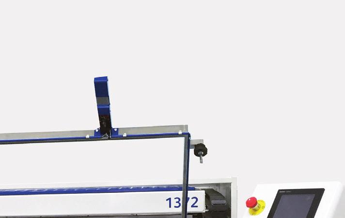
9 General arrangement Heater 2- Pneumatic Clamp Handles 3- Operation POD 4- Table Up control buttons 5- Table adjustment (depth of draw) 6- Heater Guard 7- Counter balance weights 8- Self-adjusting clamp springs 9- Control box with main switch 10- Heater rear supports

10 Specifications Foreword Please read this manual thoroughly before attempting to install or use this machine. Special attention should be paid to sections dealing with safety. It is impossible to cover all aspects of thermoforming within the scope of this manual, we are therefore available to offer advice on special problems regarding thermoforming techniques, tooling and materials. Specifications 1372SA Forming area: 1330mm x 620mm. Depth without POD: 1820mm. Depth with POD: 2000mm Sheet Size: Nominal 1372mm x 660mm Material thickness 0.25mm min. 6.0mm max Electrical Power - 17kW - Supply V, 5 wire, 3 phase + Neutral + earth, 50Hz Power - 17kW - Supply V, 4 wire, 3 phase + earth, 60Hz (North America) Width: 1820mm Length:2140mm Height:1320mm Weight: 600Kg Noise emissions Noise emissions on the Formech 1372SA are less than 70dB(A). Machine storage The Formech 1372SA must be stored in a dry environment. If the machine is not used for a long period of time, run the pump periodically (once a month). Machine transportation, lifting and moving The Formech 1372SA is prepared for transportation with the heater secured forwards with counterweights and accessories situated at the front of the machine where possible. The weight of the packaged machine is towards the front. Before lifting, remove all separate assemblies and leave the heater fixed in its position until positioning at its operating site. Remove packaging where it assists with lifting and moving. The machine must be lifted from the front taking particular care to avoid damage to the front clamping frame and control pod. The centre of gravity is at a point centre - rear of the main cabinet when viewed from the front. Ensure lifting forks pass through to the rear of the main cabinet and to the rear frame. Ensure that local lifting and handling procedures are applied and monitored by a person responsible for health and safety. 10
11 Installation The machine should be sited on a level concrete floor. Dusty or draughty areas will compromise machine performance but it is important to allow enough space (750mm) around the machine to allow access into the various panels and to ensure a good airflow to prevent overheating. During all of the following installation ensure that the power supply is properly isolated. Electrical connection An electric supply of correct voltage, current & frequency is required. An isolating switch with facility to be locked in 'OFF' position and capable of handling full current should be wall mounted, within easy reach of the operator V Three phase supply Using 3 phases, Neutral and Earth connection STAR configuration. 3P, N & E The major current consuming devices within this machine are 230V single phase. However, in order to balance the load to electricity generator's requirements, each phase of a standard three-phase supply should be connected to the L1 L2 & L3 of the machine. A neutral wire of full load capacity is required in this case. Important notice on 3 phase & Neutral connections To prevent damage of components it is highly important to check that the three phase and neutral connections are correct. The machine colours for wiring are as follows: Brown L1 - Phase 1 Black L2 - Phase 2 Grey L3 - Phase 3 Blue Neutral Green/Yellow Earth or Ground After making connections to the isolator switch in the rear cabinet it is essential to verify that the phases and neutral connections are terminated correctly. The three phases must be connected to the connections L1, L2 & L3. The Blue neutral connections must be connected to the terminal labelled N. Verify these connections using a volt-meter / multi-meter by measuring the voltage potential between the Neutral and each phase in turn. The voltage between each phase and the neutral should measure V ac. Once this is confirmed the Electrical box cover may be fitted and the isolator switch turned on. Phase Connections / Motor Rotation For all electrical connections the pump rotation direction is important. After switching the machine on press the Vacuum button on the operation screen and check that vacuum is present at the hole in the centre of the table. If there is no vacuum or if pressure is present then reverse 2 of the phase connections. THIS MACHINE MUST BE EARTHED IN ACCORDANCE WITH LOCAL REGULATIONS 11

12 Installation The 1372SA must be installed and commissioned by a Formech qualified technician. Pneumatic connection If the air supply is insufficient the performance of the machine will be compromised. The connection to the machine should be via a lockable shut off valve. Ensure that the pneumatic air supply is regulated to 6 BAR or less and is properly filtered & lubricated using good quality airline oil. A competent person must make compressed air connections. If flexible hoses are used it is strongly advised that they are of Nylon, canvas or wire reinforced rubber and suitably rated for pressure and temperature. The connection hose size should be 12mm diameter.threaded fittings are BSP. Maximum airline pressure must not exceed 5BAR or 80 PSI. The effectiveness of the prestretch and autolevel functions rely on a large volume of air being delivered rapidly to the machine. For this reason an air reservoir should be sited as close to the machine as practical. If this is not possible then large bore pipes can be used to prevent pressure drop when the above functions are used. Assembly of the control POD Where the 1372SA is delivered in a packaging crate, the control pod may be rotated or removed. Remove the three fixing screws from their fixing point at the front RHS corner of the machine, rotate the POD and refit the 3 screws to allow the POD to be at a suitable angle. Ensure the rubber seal is located in the POD stand and the fixings are tight. DO NOT LEAN ON THE POD. Counterbalance arms and weights The counterbalance arm assembly is permanently attached to the clamp. Either 5 or 6 counterbalance weights are fitted to the arms depending on the weight of a reducing frame, if fitted. These need to be set in position to balance the clamp frame. Remove the split pin and washer at the end of each arm and slide the weight towards the front of the machine and lock in place with the screw fitted to each weight. They are easily adjusted by loosening the screw with a 13mm spanner or socket. ENSURE SCREWS ARE LOCKED TIGHT. Adjustment may be required where a reducing window is fitted. Adjust the weights so that the clamp frame is balance. The clamp frame may need to be lifted to fit the RHS weight. Set the weights so that the clamping frame is balanced at a suitable height. COUNTERWEIGHTS ARE HEAVY ITEMS AND HENCE CARE MUST BE TAKEN TO PREVENT TRAPPING OF FINGERS. TAKE CARE WHEN ASSEMBLING, LOADING AND UNLOADING COUNTERWEIGHT. HEAVY ITEMS CAN CAUSE CRUSHING IF MISSHANDLED, MISSUSED OR IF DROPPED. WHEN LOADING AND UNLOADING COUNTERWEIGHTS ALWAYS ENSURE THE END STOP LOCKING SPLIT PIN AND WASHER IS REPLACED AT THE END OF THE COUNTERWEIGHT ARM. 12
13 Installation Cooling System Attaching the Cooling System; 1 - Fit the gantry sides to the two heater rails at the boltholes on either side of the moulding area with the four nuts and screws supplied. 2 - Fit the Gantry cross member to the top of the gantry sides with the four nuts and bolts supplied. The fan mounting posts should be attached to the cross member so that the fan can be positioned behind the cross member directing the fan draft forward and away from the heater. 3 - The swivel block should be supplied fitted to the fan unit. Slide this onto the cross member post and tighten the grub screws and locking nuts. Never fit the fan posts on the underside of the cross member as the fan may fall and cause injury. Mounting of the fans is a 2 person operation, precautions must be taken when lifting and working at heights. 4 - Adjust the fan unit to the required position and tighten all the grub screws and lock nuts. Using the Cooling System The corresponding FAN button on the touch screen can operate the cooling fan at the appropriate time to cool the moulding. The button changes colour when operated ON/OFF. It is worth considering the position of the fan mounting to achieve good and consistent results with different mouldings. It is essential to read and fully understand all the information in this manual relating to safety and the Safety Hazards specific to this machine before installing and operating. Operating procedures for this machine must be assessed, monitored and controlled by the person responsible for health and safety. 13

14 Introduction The 1372SA is a large sheet fed vacuum forming machine suitable for forming a wide variety of plastic materials. It has been designed with operating simplicity high on the list of priorities. Operators who have previously used vacuum forming machines will quickly become familiar with the userfriendly controller programming. Those starting out in plastic moulding will find the 1372SA more forgiving than most of its counterparts. The absence of full guarding on the semi-auto version means that the forming area is accessible from both the front and sides of the machine. This enables close inspection of the product being produced and allows for correction during the cycle. Whether required for long or short production batches or for prototyping or sampling the 1372SA adapts quickly to most needs. All of the systems used on the 1372SA have been tested, modified and refined. The result being reliability over a long period. The Formech 1372SA uses the reliable and robust Mitsubishi FX3G PLC with GOT Touch screen user interface. Formech have produced high quality functional graphic software to give an easy to use, flexible and versatile Thermoforming machine for all forms of industrial and commercial use. The 1372SA Software provides for both manual and semi-automatic functionality of the vacuum forming process. The following section explains the 1372SA control functions. 1. Main menu functions. 2. Manual Operation, Heater Settings and the Vacuum Forming Process. 3. Set up and use of the Semi-Automatic Operation. 14
15 Operation - Main Menu Functions Powering up Ensure the Emergency stop button is latched out. Turn on the mains isolator at the control panel at the rear of the machine. The main menu will be shown as below. MAIN SCREEN The Main Menu shows the options. Button descriptions are below. On machine start up default settings are loaded for the heater zones to allow for manual operation. Main screen controls New / Edit Creates a new program or modify an existing one. Manual mode Operate the machine with each action of the machine being activated by the operator. Semi automatic mode Operate the machine by selecting a stored program from the memory. The machine will operate automatically apart from the Table UP action which is activated by the operator.? Heater Default heater settings are pre-programmed for manual operation. Press this button to activate the heater. The heater must be ON to use the machine in manual or semi-automatic mode. The heater can also be switched off during machine or tooling set up. Question mark The question mark icon can be pressed at any time for an explanation of each of the icons 15


16 Operation - Manual Functions Getting started On the main menu screen. Turn the Heater ON Press the Manual Button The Manual Operation Screen will open Manual Control Functions The following section describes the manual controls of the 1372SA. Operate all of these controls independently to ensure you are fully familiar with how the machine operates and how each action behaves. There are three sets of controls: 1. The Control POD and touch screen. 2. The Table UP buttons - Front panel. 3. The Pneumatic Clamp Triggers. Emergency Stop Touch screen Clamp release button Pressure gauge Vacuum gauge Emergency Stop This momentary action latching button cuts the power to all outputs when pressed. The following message shows on the screen. The button will need to be manually unlatched to reset for normal operations to continue. Only use this button in emergency situations. 16


17 Operation - Manual Functions Table buttons (on front machine panel). To bring the table up, press and hold both the table buttons simultaneously (within 500msec). The table will rise to its top position. If the action of either button is stopped, the table will stop and the action must be repeated to continue. To send the table down, press the table down icon on the touch screen and hold down until the table reaches the bottom of its travel. To jog the table down, press the icon momentarily. Table buttons Manual Clamping Hold the clamp handles one in each hand with fingers against the triggers on the underside of each handle. Check there is no obstruction between the clamp frame and the top frame. Lower the clamp frame so that the limit switch of the RHS handle is pressed. Squeeze both clamp triggers simultaneously (within 500msec) to activate the clamping mechanism. The clamp will pull down against the top frame. To release the clamp press the Clamp Release button located on the LHS of the control POD. Clamp Frame Handles 17


18 Operation - Manual Functions Control POD Manual operation Screen Press the Manual Button on the main menu screen The Manual Operation Screen will open as shown. The meaning and operation of the buttons on this screen are shown below. Following this is a full description of the vacuum forming process. The screen icons are designed to be followed round in a clockwise direction, starting with the heaters (top left) and ending with the Table Down Button Auto-level This button enables the auto-level feature. If the plastic is sagging and not being heated evenly then the autolevel feature may be used to keep the plastic level while the heater is forward and until the heater is fully back. Heater Zone settings This Button allows direct adjustment of the heater zones whilst in the manual screen. Heater Drive This icon controls the movement of the heater. The direction of heater movement is reversed each time the button is pressed. Pre-stretch To inflate the plastic before moulding; press the Prestretch icon. This feature is particularly useful if the mould is high because it keeps the plastic at a more even thickness throughout the moulding. Prestretch may be used as the table is rising to keep the bubble inflated. Vacuum The vacuum icon is used to apply vacuum to the table. The vacuum tank is continually evacuated by the vacuum pump. The air is evacuated by the vacuum tank combined with the vacuum pump. In manual mode the timer counts up. This button latches ON when pressed. Press again to turn OFF. Fans Pressing the fan icon will turn the cooling fans ON. Press again to turn OFF. In manual mode the timer counts up. 18
19 Operation - Manual Functions TABLE DOWN FINISH Release The release icon is used to blow compressed air between the mould and the finished moulding. Too long a release may distort the moulding. This is a momentary HOLD TO RUN button. Table Down This Button drives the table down when pressed. This is a momentary HOLD TO RUN button and can be used to lower the table is short steps to gently assist with releasing the mounlding without damage if required. Finish This Button returns to the main menu. 19
20 Operation - Manual Functions Manual Setup Select the Manual icon on the main screen. The heater power for manual mode defaults to values of approximately 70%. The standby level is 50%. The heaters are controlled by the PLC system to vary the output of individual zones as displayed on the touch screen. Allow minutes for the heaters to reach operating temperature before attempting to run any mouldings. To change the heating zone settings press the heat zones settings button on the manual operation screen. The individual zones may be set up to provide an even spread of heat. To achieve the best results set the inner zones lower than the outer zones and remember that the rear of the heater will always run hotter than the front. Having set the heaters, slight adjustments may have to be made depending on the mould design, plastic type etc. We recommend that initially all zones are set to 70% power. This will then allow the operator to increase or decrease individual zones as required. There are 15 heating zones on the 1372SA machine Z1 to Z15. Under each Zone number the actual percentage of heat is displayed. Press on a zones to change the set value. The following screen opens. When one of the zones is selected, it will take you to the SET ZONE HEAT LEVEL % screen. All you have to do is to select the most appropriate % for a particular zone. You will then be taken back to the 18 heating ZONE screen to select the other zones. 20
21 Operation - Setup functions for semi automatic use Manual Cycle Once the mould is correctly located on the mould table a manual cycle may be attempted. Manual Plastic Clamping Place the plastic over the forming area and ensure the material covers the top frame seal completely. Once the clamp frame is over the plastic correctly, squeeze both clamp triggers simultaneously as previously described. The following describes the functions of the icons after the plastic has been clamped. Heating Press the heater icon and the heater will be driven forward over the plastic and stop automatically when the front limit switch is triggered. The heating of the plastic sheet may be checked by pressing the heater icon to send the heaters to the rear momentarily as described earlier. Autolevel If the plastic is sagging and not being heated evenly then switch the autolevel feature on, in the centre of the touch screen. If the plastic sheet drops and breaks the sensor beam, short bursts of air will be blown in to the chamber under the heated plastic ensuring the plastic remains level. Moulding Once the plastic is at the correct temperature for moulding, then send the heater to the back position by pressing the heater button. Once the heater has reached the back limit switch and stopped press both table buttons simultaneously (table up on guarded machines) to raise the mould into the plastic. Press the vacuum button to apply vacuum to the table. Pre-stretch If the moulding is quite high it may be necessary to prestretch the plastic before moulding takes place. To do this press the pre-stretch button when the heater is in the back position. Cooling & Release At the appropriate time the fans may be turned on to start the plastic cooling process. Once the plastic has cooled sufficiently the release icon may be pressed to blow the moulding off of the mould. The moulding is now complete and the table may be lowered and the clamp frame unclamped. 21
22 Operation - Setup functions for semi automatic use To set up the PLC for a semi automated cycle ensure the heater is in the back position and the clamp frame is unclamped. Press the NEW/EDIT button on the Main screen. This allows you to choose to edit an existing job or create a new job memory. Press NEW to open the setting screen. The name of the job memory being edited is shown Blank if setting a new job. The icons on the SETTINGS screen allow the time parameters to be programmed. Press each of the coloured icons in turn and enter the desired timings and settings. Button functions are summarised below. Further details are shown in the settings section. Heater Press the Heater icon to set the heating time. Enter the number of seconds required. Release Press this icon to set the pre-stretch time. Enter the number of time required. Time can be set to 1/100th of a second. Vacuum The vacuum icon allows you to enter the time that the vacuum pump stays on. This time starts from the point that the table reaches the top position. Fans and fan delay If the fan delay is set to 10 seconds then the fans will start 10 seconds after the point that the table reaches the top position. The fans will run for the set run time allowing the vacuum to pull the sheet in tightly around the tool before cooling the part. 22
23 Operation - Setup functions for semi automatic use Table down delay The table down delay time allows adjustment of the moment that the table descends. For most purposes use the same time as the release time. If additional release air is required as the table descends then reduce the table delay time whilst keeping the release time greater. Release Press the release icon to set the time for air to blow the formed plastic off the mould. Enter the number of seconds required. Time can be set to 1/100th of a second. Auto Level Press this icon to activate the auto-level. This allows compressed to blown under the sheet during the heating process so that the sheet remains horizontal to the heaters at all times for even heating. Zones This icon allows you to adjust all of the 15 heater zones on the 1372SA to the desired percentage of heat. Adjustable by increments of 5%. Standby The standby feature allows you to reduce the temperature of the quartz elements when they are not required in the rear position. As soon as the heaters come forward they very quickly power up to the correct temperature. 23

24 Operation - Setup functions for semi automatic use On the SETTINGS screen you will need to enter times and settings for each of the functions of the machine represented by the icons. When you select the ZONES button, the heater ZONES screen will be displayed as shown below. There are 15 heating zones on the 1372SA machine Z1 to Z15. Under each Zone number the actual percentage of heat is displayed. When one of the zones is selected, it will take you to the SET ZONE HEAT LEVEL % screen. All you have to do is to select the most appropriate % for a particular zone. You will then be taken back to the 15 heating ZONE screen to select the other zones. 24
25 Operation - Setup functions for semi automatic use When the STANDBY button is selected from the SETTINGS screen it allows you to adjust the percentage of heat. We recommend 50% Standby for the heaters in the STANDBY rear position. You will then be taken back to the SETTINGS screen. When the HEAT Button is selected, it allows you to adjust the time that the heaters come forward over the material. Press the set value in the RED Box and use the digital keypad to set a time. When a new time is entered in the keypad press ENT When the PRE-STRETCH is button selected, it allows you to adjust the time that the pre-stretch is activated. Press the set value in the RED Box and use the digital keypad to set a time. When a new time is entered in the keypad press ENT. Pre-stretch times can be set to 0.01 Secs. 25
26 Operation - Setup functions for semi automatic use When the VACUUM button is selected, it allows you to adjust the time that the vacuum is activated. Press the set value in the RED Box and use the digital keypad to set a time. When a new time is entered in the keypad press ENT When the FAN icon is selected this screen is opened. There are 2 times to set for FAN operation. When the FAN DELAY button is selected, it allows you to adjust the time that the Fan is delayed after the table is UP. Press the set value in the RED Box and use the digital keypad to set a time. When a new time is entered in the keypad press ENT 26
27 Operation - Setup functions for semi automatic use When the FAN RUN TIME button is selected, it allows you to adjust the time that the Fan is activated after the fan delay time. Press the set value in the RED Box and use the digital keypad to set a time. When a new time is entered in the keypad press ENT When the RELEASE button is selected, it allows you to adjust the time that the release is activated. Press the set value in the RED Box and use the digital keypad to set a time. When a new time is entered in the keypad press ENT.Release times can be set to 0.01 Secs. When the TABLE DELAY button is selected, it allows you to adjust the time that the table remains UP after the end of the Vacuum time. Press the set value in the RED Box and use the digital keypad to set a time. When a new time is entered in the keypad press ENT.Table delay times can be set to 0.01 Secs. 27


28 Operation - Setup functions for semi automatic use When all adjustments are complete press the SAVE OR EXIT button. The following message will prompt to confirm save or exit. This grey MEMORY screen will be displayed if you select the SAVE OR EXIT. Select as memory location for the changes. The final parameter review screen opens. The parameter review screen allows final review of the settings. All parameters can be changed at this point. Press on any value and a keypad allows adjustment. The job name may be changed with and keypad. Press save to return to the main menu. 28


29 Operation - Semi-automatic cycle Semi-Automated Cycle With the clamp frame in the up position set the required times for Heater, Prestretch, Vacuum, Fans & Release. Select the semi automatic icon Select the required job form the list. There are 20 Job Records. SEMI AUTOMATIC OPERATION This screen displays the saved job details including the times for Heating, Vacuum and Fan. The operations of the machine follow the icons in a clockwise direction starting with the heaters in the top left hand corner of the screen. 29
30 Operation - Semi-automatic cycle Clamp the plastic and press the heater button to start the cycle. Once the heater is forward then the time display will count down the heating cycle time. Once the heating cycle is complete the PLC will automatically send the heater back and pre-stretch the plastic if a pre-stretch time has been entered. The operator must at this stage raise the table. When the table has reached the top position then the mould, cooling and release cycles will be performed automatically. At the end of the release cycle the table is sent down by pressing the table down icon on the touch screen. When the table is in the down position press the clamp release button on the control POD and lift the clamping frame. Remove the finished moulding. Other notes on Semi-automatic Operation. Manual intervention of the heating cycle when in Semi-Automatic mode: If the heated plastic becomes ready before the time is complete then press the heater button to send the heater back. As soon as the heater reaches the back position it will continue through to the next stage of the cycle. If more heat is required at the end of the heat time send the heater forwards again to continue heating. Note: 1. This action must be performed before the heater reaches the back position. 2. The heat cycle timer will restart and therefore the heating cycle must be finished manually when the plastic is ready. Manual intervention of the Forming cycle when in Semi-Automatic mode: If manual intervention is required when forming mouldings after the table has been lifted, press the vacuum, fan or release butttons to over-ride the forming cycle and finish the process manually. 30
31 Heater Settings 1372SA - Zone Layout SA Heater element power arrangement Front 400W 300W 300W 300W 300W 300W 300W 300W 300W 300W 400W 300W 250W 250W 250W 250W 250W 250W 250W 250W 250W 300W 300W 250W 250W 250W 250W 250W 250W 250W 250W 250W 300W 300W 250W 250W 250W 250W 250W 250W 250W 250W 250W 300W 400W 300W 300W 300W 300W 300W 300W 300W 300W 300W 400W Element power in Watts Front Heating Zone Control and Adjustment The heating zone control is adjusted by the touch screen. When adjusted this will allow the heat of the corresponding heater zone to be set. Reduce or increase the percentage to each zone to set the required heater power level and review as necessary. See also the section regarding Operating Techniques for heater settings. 31

.")
32 Other Controls and user adjustments Table Speed adjustment TAKE CARE WHEN REACHING TO THE BACK OF THE MACHINE. THERE MAY BE VERY HOT SURFACES IN THIS AREA. ENSURE THAT THE CLAMP FRAME COUNTERWEIGHTS ARE ADJUSTED FULLY FORWARD BEFORE CARRYING OUT THE BELOW PROCEDURE. THIS IS TO PREVENT THE CLAMP SUDDENLY SWINGING UP AND THE COUNTERWEIGHTS DOWN IN THE EVENT OF A PNEUMATIC OR POWER FAILURE. Two table speed adjustments are situated on the lower right hand side of the rear panel. (when viewed from the rear of the machine). These are flow regulators to adjust the air that is exhausted from the table pneumatic cylinder. Inserting a 6mm hexagon key in the centre and rotating clockwise or anti-clockwise will adjust them. Adjust the regulator clockwise to reduce the air exhaust to reduce the cylinder / table speed. Adjust the regulator anti-clockwise to increase the air exhaust to increase the cylinder / table speed. The top flow regulator will adjust the table UP speed. The lower flow regulator will adjust the table DOWN speed. If water accumulates in the plastic reservoir, unscrew the bleed screw to release the water, then tighten up again. Please check this periodically. Clamp speed adjustment - opening Clamp speed adjustment - closing Table up speed adjuster Table down speed adjuster Moisture drain Main air inlet 32

33 Other Controls and user adjustments Table Height Adjustment The lower stop point of the table may be adjusted easily from the outside of the machine. The adjustment is performed by adjusting the table stop shaft situated below the left hand side panel. For convenience the shaft has a 22mm hexagon end. A rotary handle is supplied with the machine to assist with the manual adjustment. Always make adjustments with the table in the raised position. Rotate the handle clockwise to lower the table height. Rotate the handle anti-clockwise to raise the table height. Clamp Frame rear spring adjustment The clamp frame is spring loaded at the rear. The springs are locked in place with 2 M10 nuts. The loading of the springs may need to be adjusted, for example, when using thinner or thicker plastics materials to assist clamping or when a reducing place is fitted. To adjust the spring loading loosen the lower Nut for each spring and adjust the upper nut to suit. Tighten the lower nut to lock against the upper nut. TAKE CARE WHEN REACHING TO THE BACK OF THE MACHINE. THERE MAY BE VERY HOT SURFACES IN THIS AREA. Clamp Frame speed adjustment The clamp speed may be adjusted using the small exhaust flow controls on the clamp valve in the same way as the table speed. 33
34 Other Controls and user adjustments Front clamp limit switch adjustment The front material clamps may need adjustment when reducing plates are fitted. The clamp limit switch is located on the Right hand clamp. This switch is sprung loaded. The switch must be activated to close the clamp. When a reducing plate and plastic is fitted in the aperture the limit switch may not close and the clamp will not operate. To adjust the switch, loosen the 2 nuts retaining the spring loading of the switch so that the switch is positioned lower and is activated when the clamp is lowered. Clamp frame Jacking bars - Front and Rear The clamp frame has jacking bars that can be screwed out to provide a bow in the clamp to assist with clamping. Loosen the bottom screws and tighten the top screws to give better clamping. Adjust to suit the desired profile. Counterweight adjustment - loading and unloading Counterweights are easily adjusted by loosening the screw with a 13mm spanner or socket. ENSURE SCREWS ARE LOCKED TIGHT AFTER ADJUSTMENT. Adjustment is required if, for example, a reducing window is fitted. Adjust the weights so that the clamp frame is balanced. Touch screen control POD position The tilt angle of the touch screen POD is adjustable. Loosen the M5 locking screw on the underside of the pod arm. Set tilt position to suit the height of the operator. Heater motor speed The Heater motor speed may be adjusted. It is set to an optimum factory setting so adjustment is not normally necessary. On occasions where adjustment is necessary this can be performed by adjusting the potentiometer on the heater motor inverter. The speed is shown on the invertor. If this speed is adjusted then it is essential to adjust the positions of the front and rear heater limit switch to suit the drive deceleration position. Deceleration may also be adjusted using the inverter function mode. 34

35 Other Controls and user adjustments Fixing mould tools There are four mould tool fixing points at each corner of the table to accept M6 Screws. Use these to fit full sized mould tool mounting boards, maximum thickness 10mm. Thicker tool mounting may be used if the boards are reduced in size allowing a gap between the board and aperture or if the edges are chamfered. Further holes may be drilled and tapped for M6 thread. Avoid the centre 200mm section along the full left to right length in the centre of the table when positioning mounting points. 35
36 Fault diagnostics/maintenance Before any maintenance work is carried out both electrical and air supplies must be locked in the OFF position. Only a qualified electrical technician may work on any parts carrying mains voltage. That person is responsible for ensuring that the machine is in a safe condition before allowing services to be restored. Electrical The PLC relies on the limit switches continually reporting correct mechanical positioning information. Although extremely robust, limit switches are frequently activated and the operating arm may become loose etc. If a limit switch is not operating properly neither will the PLC operating system. Limit switch faults will stop the auto cycle and may prevent the machine functions completely. A logical approach to detecting the fault begins with an exact appraisal of the fault scenario. Much time can be wasted looking in the wrong areas for a problem that, when found, was obvious. Assessment of the fault will entail understanding which interlocks operate to prevent further actions. Typical fault scenarios Table will not rise. Check that the heater is in the back position and that the heater-back limit switch has been operated. Check that the clamp frame is properly engaged and the limit switch operated. The clamp mechanism will not engage. Check the clamp down limit switches. Is the air turned on? Heater will not come forward. Check that clamp and table are down and the limit switches operated. Autolevel blows the plastic into heater. Check beam sensor alignment. 36
37 Fault diagnostics/maintenance Before any maintenance work is carried out both electrical and air supplies must be locked in the OFF position. Only a qualified electrical technician may work on any parts carrying mains voltage. That person is responsible for ensuring that the machine is in a safe condition before allowing services to be restored. Heater The flexible cable chain between the heaters and the control cabinet contain a number of heatproof power and thermocouple cables. Due to the continual motion of the heater these may eventually suffer from fatigue and require replacement. Only the correct grade of cable should be used, and the work carried out by a skilled technician. The quartz heating elements should be periodically inspected for damage to the quartz elements and to make sure that they are securely mounted and that the electrical connections are tight. For the reasons stated, the elements, associated cables, connectors, fuses and are specifically excluded from our standard warranty. Elements are easily changed, ensure the power is isolated and the air supply is switched off. Remove the screws from the heater cover and remove. Disconnect the faulty element and undo the retaining nuts and lower the element to remove. The fitting of the new element is in reverse. It is recommended that the heater tray electrical connections are periodically checked. This requires the removal of every terminal block cover on the element tray and systematically tightening every terminal screw. This procedure must be performed within the first 6 months of use or sooner if usage is heavy. Repeat this procedure every 12 months thereafter. Replacing a heating element If the plastic is not being heated evenly and there is an obvious cold spot then follow the below procedure. This procedure is simplified if the checks are performed from cold Switch off machine and let heater cool completely, this will take at least 45 minutes. Bring the heater half way forward, place hand near but not on elements to see if they are still hot. If they are, let machine cool for a further 15 minutes. When elements are completely cool, turn on each zone individually and very carefully feel each element connected to that specific zone. The difference in temperature will quickly become noticeable. If one or more elements fail to heat then follow below. Service\Repair Disconnect the electrical mains supply. Bring the heater completely forward. Remove the self tapping screws securing the slotted heater cover and place to one side with the cover. Remove the cap from the terminal block associated with the faulty element, loosen the terminal block screws and remove the element leads and insulation sleeves. Remove the 4 M4 nuts securing the element to the tray placing a hand underneath the element to prevent it from falling. Remove the element. Fit the new element, feeding the connection leads through the tray and secure it in place with the retaining nuts. 37
38 Fault diagnostics/maintenance Before any maintenance work is carried out both electrical and air supplies must be locked in the OFF position. Only a qualified electrical technician may work on any parts carrying mains voltage. That person is responsible for ensuring that the machine is in a safe condition before allowing services to be restored. Replacing a heating element (continuation) Slide on the insulation sleeves, replacing with new if perished or damaged. Ensure that the connections are fully tightened and correctly wired. Replace the terminal block cover and check that no cabling is touching any metal parts. Replace the slotted heater cover and fit the self tapping screws. If the vacuum appears to be weak or non-existent check the following: The mould baseboard is not restricting the vacuum inlet in the drape table. NOTE: If the mould baseboard is too soft it may pull down under vacuum and block the vacuum inlet. The mould is adequately vented to allow trapped air to be evacuated. The table and clamp seals are in good order and the table is locking properly at the top of its travel. There are no open holes in the drape table. The filter box cover is correctly fitted. The vacuum valve is operated by a pilot valve using compressed air, this may not operate if the pressure is too low. Auto-Levelling system ISOLATE COMPRESSED AIR SUPPLY BEFORE ATTEMPTING ANY OF THE BELOW. ALWAYS DISABLE THE TABLE & CLAMP BEFORE ATTEMPTING TO LOCATE OR ADJUST THE OPTICAL SENSOR. This machine is fitted with an automatic sheet levelling system. An optical sensor directs a beam of infrared light across the machine. The system comprises of a transmitter and receiver. If the beam is broken air is pumped into the machine cabinet under the plastic lifting it until beam transmission is re-established. When the plastic is heated it begins to sag and cuts the beam, the compressed air lifts the plastic until it has cleared the beam. The air is then shut off until the plastic sags again. The intervals between the air turning on & off may be very short. The optical sensors are located under the top-frame at the sides. The alignment between the optical sensor and the reflector is finely adjusted. It may require re-adjusting if the machine has been transported or used roughly. If the heater is left for any time over the forming area (without plastic clamped in) sensors may become distorted. The sensor may fail if it is exposed to high temperatures. 38

39 Fault diagnostics/maintenance Auto-Levelling system (continuation) Adjustment may be carried out by slightly bending the sensor mounting plate. The sensor has two small adjusting screws that alter sensitivity and range. These have been set at the factory and are unlikely to have moved. Only adjust these if you cannot make the sensor work properly by any other means. If no LEDS are visible at any time then the sensor may have lost its power connection or become faulty. The Auto-Level may be working properly but blows the plastic up higher than the top-frame level. If this is the case adjust both sensor mounting plates slightly downward Vacuum Warning: never oil any part of the vacuum pump. It is designed to run dry and could be severely damaged by lubrication. The vacuum circuit requires very little maintenance. The inlet filter is mounted on top of the vacuum pump situated under the table on the RHS of the machine. Unclip the top cover of the filter box. The paper cartridge filter prevents particles and dust from entering the vacuum pump. This filter should be inspected periodically and blown out if dirty or replaced if in poor condition. Do not run the machine without this filter. Worn or damaged seals around the perimeter of the table may cause loss of vacuum. These are consumable parts and require replacement after some time. To replace seals follow the procedure relating of Clamp & Table seals in this section. Other causes of vacuum loss are loose or damaged flexible pipes or fittings, blocked filters or build up of contamination in the vacuum valves. The valves should be dismantled and cleaned with paraffin or diesel fuel. Be sure to remove all traces of the solvent used before re-assembling. Lubricants or other liquid may cause irreparable damage to the pump if introduced into the vacuum circuit. Vacuum system If the vacuum appears to be weak or non-existent check the following. The mould baseboard is not restricting the vacuum inlet in the drape table. NOTE: If the mould baseboard is too soft it may pull down under vacuum and block the vacuum inlet. The mould is adequately vented to allow trapped air to be evacuated. The table and clamp seals are in good order and the table is locking properly at the top of its travel. There are no open holes in the drape table. The filter box cover is correctly fitted. The vacuum valve is operated by a pilot valve using compressed air, this may not operate if the pressure is too low. If all the above points are OK and you can hear the pump running when you switch it on then one of the following points will be the cause of the problem. If the pump does not run, refer to the Electrical trouble shooting section above. 39
40 Fault diagnostics/maintenance Vacuum system (continuation) A pipe is loose, damaged or blocked. The pump filter is blocked. The vacuum valve is blocked or corroded. The vacuum pump is blocked or corroded. If the heater has been left in the forward position, with no plastic in the clamp frame, the table will start to overheat. The pipe attached to the back of the table will shrink and constrict the passage of air. Pipes become less flexible over time and may loosen or crack. Pneumatics Providing there is a good filtered regulated lubricated air supply, using good quality airline oil, maintenance will be minimal. However, a thorough inspection of the machine is necessary from time to time. Any mechanical damage of pipes and fit-tings should be dealt with before re using the machine. Always lock air supply OFF and bleed out system air before attempting any maintenance of air system. Oil dripping or air escaping from a cylinder nose bush usually suggests that the seals require replacement. Seal kits are available for cylinders. Internal leaks within cylinders and valves are usually detected when a cylinder creeps into the wrong position or is air continually seeps out of the valve exhaust port. Again seal kits can be provided, please specify cylinder/ valve number & model when ordering. Other problems that solenoid valves may suffer from are:- 1) Lack of electrical supply - Check appropriate circuitry 2) Solenoid has become open circuit - Replace with new solenoid 3) Return mechanism jammed or broken - Dismantle valve to investigate. Replace if required. 4) Wet or dirty air supply - Check condition of air compressor and condensate management system. If the machine is to be not used for more than a few hours the compressed air system should be depressurised. As dictated by standard engineering practice, a drain leg should be fitted upstream within a reasonable distance of the machine. The pressure regulator must be set at least PSI. less than the supply pressure to maintain an even flow. We strongly recommend fitting a lubricator to the main air supply if the machine is intended to be used for daily production. This will extend the working life of the pneumatic cylinders and valves. Adjust the lubricator such that the oil level drop can be noticed over the course of one days full use. Do not allow excessive amounts of oil to enter the pneumatic system. Excess oil can be drawn into the vacuum circuit via the prestretch and release air systems, this will severely damage the vacuum pump. Many problems can be caused by water in the pneumatic system. 40
41 Fault diagnostics/maintenance Table Cylinder Maintenance The pneumatic table lift assembly is a potentially hazardous area of the machine to perform repairs, maintenance and adjustments. The following guidelines must be followed when performing maintenance on this area. It is recommended that maintenance of this are is conducted by qualified and competent persons. Lift the table using the 2 handed control system to a point just below the top frame. Remove all air supply from the machine and switch off the power. Remove both side panels and fit supports on both sides between the scissor base and the underside of the table and fix in place. The prop must be of suitable strength to take the weight of the table. Remove both the outlet 10mm air pipes that feed the cylinder from the table valve. The table will rest on the fitted props. Check that the table and props are secure. Remove the 2 front panels. Full access is now available to the table cylinder and table mechanism. For general maintenance and cylinder removal: Check all scissor pivot fixings, guides and bearings for wear, tighten and / or replace as required. To remove the cylinder, remove the 4 cylinder base fixings, loosen the rod end lock nut, rotate the cylinder rod and unscrew from the rod end post. Disassemble the cylinder and replace seals as required, reassemble and refit the cylinder. Check adjustments and set as required. Fit the front panels, reconnect all air pipes, and connect the air and power. Drive the table up and remove the 2 table props. Check operation and fit side panels. General lubrication The following should be checked periodically, and lubricated when necessary; Racks & pinions, bearing housings, drive chains, door hinge blocks. Where possible use a high temperature lithium grease, except lower heater drive chains (where fitted) that require extra high temp. Clamp & Table Seals These are regarded as a consumable part and should be replaced when signs of wear become apparent. (See section dealing with Vacuum) Clamping pin seals should be monitored for wear and replaced as required. Failure of these may affect the auto-levelling and pre-stretch function. To replace a damaged or worn seal Remove the existing seal with a sharp knife. Remove as much of the original sealant as possible. Using masking tape, make a frame inside where the seal will go (table) or outside (clamp) squeeze some glue around the area where the seal is to be placed. Do not be too economical with the glue. Bed down a strip of silicon seal until it is firmly seated in the glue. Do not attempt to stretch the rubber seal, it will contract back to its original size before the glue is dry. Cut the ends at 45 degrees. Continue this process for all 4 sides of the seal. Fill up any gaps in the mitred joints with glue. Place masking tape over the mitred corners to help keep them firmly positioned until the glue is dry. Leave overnight, then remove masking tape and trim any excess glue off with a sharp knife. We supply a kit comprising the necessary seal and glue for the 1372SA. 41
42 Fault diagnostics/maintenance Cleaning Ensure the inside of the machine and the heater tray is cleared of dust, dirt and debris. Do not allow dirt and loose particles to build up, particularly on the heater tray. Lubrication The 1372 requires minimum lubrication. The main lubrication area is the table guide bars situated on either side of the table. Apply a general purpose grease when required to assist with table movement. Apply grease to the scissor pivot points when this area is undergoing general / cylinder servicing. Panel Seals The rubber seals fitted to the side panels should be periodically inspected and replaced where necessary. Failure of these seals will prevent the correct functioning of the auto-level and pre-stretch functions. DUE TO THE FACT THAT REPLACEMENT OF THE PANEL SEALS REQUIRES THE PANELS TO BE REMOVED, THE MACHINE MUST BE COMPLETELY ISOLATED FROM BOTH ELECTRICAL AND AIR SUPPLIES WHEN SUCH WORK IS PERFORMED. To replace the seals, isolate power and air supplies, remove the panel that requires service and remove the damaged seal. Apply silicone sealant to the sealing area and replace with new seal strip. Only use original parts. Allow to dry for minimum of 2 hours before refitting the panel. Service Support If you are unable to cure any problem relating to your machine, or if you wish to order spare parts please contact us at the contact number on the front of this manual stating the model, 1372SA semi-auto, the serial no. (on specification plate), and a full description of the fault or parts you need. 42
43 Forming Difficulties The purpose of the following section is to help the user in overcoming some problems frequently encountered in thermoforming. Please remember that the majority of thermoforming faults are caused by incorrect machine setting or poor mould design. This section is a guide only and cannot impart the practical experience and skill that any user will eventually attain. PROBLEM CAUSE REMEDY Lack of definition Material too cold Increase heating time/temp. Webbing (small pleats at corners of mouldings) Webbing Shrinkage of moulding (after removal from mould) Mould too cold Insufficient vacuum Incorrect pre-stretch height Incorrect heater zoning Material overheated Vacuum speed too fast Mould design/position Excess material Product removed from mould too quickly Warm mould Adjust vacuum timings Check vent holes on mould Is mould restricting vacuum flow? Are vacuum tracks in mould adequate? Adjust pre-stretch flow and/or time. Check panels for leaks Adjust problem zones Reduce heating time Regulate to suit Increase tapers or radii. Use plug assist. Move cavities further apart (Multiple moulds) Reduce material size or use 'dummy' moulds Increase timings to allow longer mould contact Increase cooling time Moulding too thin in areas Incorrect heater zoning Decrease temperature in problem zones Too much pre-stretch Cold spots Mould too cold Material not consistent Decrease flow or timing Check elements are working. Are there any draughts? Warm mould Consult supplier Creased or distorted formings Excessive mould release pressure or timing Adjust to suit Thick tops on finished mouldings. (Chill marks) Marks on finished mouldings Material too hot at release Material thinning Mould too cold causing rapid cooling on contact Design of mould Insufficient pre-stretch Material too hot or too cold Damaged or dirty mould Water on mould Increase cooling time Adjust heater zoning Increase mould temperature. Adjust flow on water cooled moulds Use plug tool to assist material flow Increase pressure, flow or time Increase heating time/temp. Repair or clean mould. Use blowgun between formings. Decrease spray mist 43

44 Warranty Reliability and a long service life are synonymous with the Formech brand. However, as with any machinery, certain parts will require periodic replacement and regular maintenance and care will prolong machinery life. Clamp Seals The silicon seals applied to the mould table and to the top aperture of the machine (clamp) are seen as being consumable parts, their service life will depend on how the machine is treated and how often it is used. The table and clamp seals are not covered by our warranty. Heating elements The Quartz infrared heating elements supplied with this machine are manufactured using quartz tube and therefore may break or crack with impact or physical shock. The Quartz heating elements contain internal filaments, which become extremely hot when power is applied. The wire expands and contracts as it heats and cools. Eventually, due to the continual expansion and contraction, the wire will fracture and a new element will be needed. This may take 10 years or more. Because of this we are unable to apply our standard warranty to Quartz heating elements. However our experience is that this form of infrared heating is durable, reliable and more resilient to shock and impact than similar ceramic products The heating elements are not covered by our warranty. Vacuum system The vacuum system on this machine is fairly simple but uses high quality components throughout. The life expectancy of the vacuum system will be compromised by the ingress of dirt, shavings, dust, liquid etc. A cartridge filter is fitted to the vacuum pump inlet to prevent particle being drawn into the vacuum chamber. Monitoring of the condition of the filtering system will prolong vacuum performance. Replace the filter if it becomes degraded with dirt and particulate. THE VACUUM CIRCUIT INCLUDING THE VACUUM PUMP WILL NOT BE COVERED BY OUR WARRANTY IF THEY ARE FOUND TO BE BLOCKED WITH FOREIGN MATTER OR CORRODED BY THE INGRESS OF LIQUID. 44
45 Electrical Circuit information Overview The following is an overview of the 1372SA control circuit showing the safety related parts of the control system. 1372SA Electrical supply RST Option SW3 SW SW1 24V DC Heater switch inputs S6, S7 Table switch inputs S5, S8 Estop & clamp down input Beam sensor input Power distribution & Circuit protection Emergency Stop Module SW Handed control module SW2 2 Handed control module PLC Touch screen user interface Clamp Down output SV6 Safety related control system Table up output SV2 Heater Triac Control Zones 1-15 Heater Outputs Zones 1-15 R2-2 Table down output SV3 Air Solenoid valve Outputs SV1, SV4, SV5 Motor outputs C1, R8, R9 Heater Motor drive Circuit wiring information consists of the following: P1. Power distribution. P2. Emergency Stop Functions P3. Inputs and safety related parts on the control system. P4. Outputs. P5. Heater Outputs. P6. Clamp & Safety Related parts of control system. P7. Major components parts listing Interlocking devices Rear heater limit switch, SW4 Prohibits Auto-level when closed. Prohibits pre-stretch, release, vacuum and table up command when open. Table down, SW5 Prohibits Heater Forwards when open. Heater Forwards Limit switch enables auto-level when closed 45
46 Electrical wiring diagram P1 A B C D E F G H I 1 2 N 3 4 L1 L2 L3 5 63A Isolator Switch Fuse 1 2A L1 230V ac to Ctrl Supply Page 2-D9 Page 1 Fuse A L1 230Vac to 24Vdc PSU supply Page 3-I9 Fuse 3 5A L1 230Vac to Heater Motor Inverter Page 2-D11 Fuse 4 5A L2 230Vac to Fan 1 Page 5-E14 Fuse 5 5A L3 230Vac to Fan 2 Page 5-F14 L1 Pump L2 Pump L3 Pump Page 4-F5 L3 Top Heater L2 Top Heater L1 Top Heater Page 6-E2 N Page 3 - I Page 4 - I8 Page 5 - I Page 6 - I3 Page 7-I Formech1372SA PLC February SA plc 1. Power V MCB 1 40A Type B MCB 2 40A Type B MCB 3 40A Type B MCB 4 10A Triple Type B 46
47 Electrical wiring diagram P2 A B C D E F G H I VDC Page 3 - I12 Page 2 Yell POD Rd Option ESTOP Reset SW5 F1-240V ac Page 1 - C10 F3 (Inverter) - 240V ac Page 1 - C10 SW3 N.C. (Inverter signal CM) - Page 4 H3 SW4 N.C. Grn Blu Estop activated Page 3 - D6 A1 Y1 Y2 Grn Y43 XPS-AC A Y44 0v Page 3 G12 24V DC Page 4 B12 Page 5 - B2 Page 6 - C2 240V ac Page 3 - F2 Page 4 - D6 Page 4 - F13 Page 5 - F14 Page 6 - E11 240V ac Page 4 E2 Formech1372SA PLC February SA plc 2. Estop 47
48 Electrical wiring diagram P3 A B C D E F G H I SW7 Heater Back limit N.O. SW6 Heater Fwd limit switch N.C. X0 X1 N Page 3 Level Sensor RX Level Sensor TX R2-1 N.O. Table is up Reed SW 8 N.O. Fuse 6-2A SW5 Table is Down Limit Sw NO Estop activated Page 2 E3 R3-2 NO A1 R1-1 N.O. R1 Heater is Back Relay A2 Page 2 G V ac SW1 SW2 Green NO (SW1a) Yell NO (SW2a) Blue NC (SW1b) Red NC (SW2b) Page 1 - I7 Yell Red Blue Green A1 A2 Grn Relay 2 Table is Down X2 X3 X4 X5 PLC FX3G 14 MT DSS X6 X VDC S/S HMI GT 1055 QSBD screen 11 T13 T12 T11 T11 A1 A2 2H Handed Control Module XPSBA NO Heater is Back R1-2 SV2 Table UP Valve Solenoid 230Vac 5W L1 Ctrl Page 1 D10 0v 24VDC SMPSU 24v L N N 0VDC Page 4 - F13 Page 5 - D2 24VDC Page 2 a3 0VDC Page 2 - I Page 6 - B2 Formech1372SA PLC February SA plc 3. Inputs V ac Blu Brn 48
49 Electrical wiring diagram P4 A B C D E F G H I vDC Page 2 G - 8 +V0 +V1 +V Page 4 PLC FX3G 14 MT DSS Y3 Y2 C1 Pump Contactor 24vDC VACUUM PUMP M SV3 Table Down Valve Solenoid 230V ac Overload Y0 Y1 Fwd Rev Page 2 - G11 L CM N Inv 1 TH N M Estop CTRL Page 2 D-12 0VDC Page 2 G12 +V3 +V4 +V5 Y4 Y5 Expansion Module FX2N-8 3YT - ESS - UL 240V ac Page 2 G - 9 Buzzer 1 24VDC Page 1 F7 L3 L2 L1 R5 Table Down R6 Prestretch R7 Release 240V ac Page 2 G W SV1 Vacuum Valve Solenoid 230V ac Table is down R2-2 N.C. SV4 Pressure (Pre-strech) Valve Solenoid SV4 230Vac Page 1 - I7 SV5 Pressure (Release) Valve Solenoid 230Vac N Formech1372SA PLC February SA plc 4. Output V ac 49
50 Electrical wiring diagram P5 A B C D E F G H I Expansion Module FX2N-16 3YT - ESS - UL 4 channel triac Output module W 1000W 1500W 1500W 750W 750W 750W 900W 1000W 1000W 750W 750W 750W 900W 1000W 1000W 24VDC Page 2 - G8 PLC FX3G 24 MT DSS 0VDC Page 2 G12 0v L1 TH Page 1 H7 L2 TH L3 TH Quartz Heater Zones N Page 1 - I7 Page 5 +V0 +V1 Y10 Y11 Y12 Y13 Y14 Y15 Y16 Y17 Y20 Y21 Y22 L23 Y24 Y25 Y26 Y27 Z1 Z1 Z2 Z3 Z4 Z5 Z6 Z7 Z8 Z9 Z10 Z11 Z12 Z13 Z14 Z15 0v 0v 0v 0v 0v 0v 4 channel triac Output module 2 4 channel triac Output module 3 4 channel triac Output module 4 R8 Fan R9 Fan F4 Page 1 E - 10 F5 Page 1 F - 10 FAN 550W M M FAN 550W Z1a Z1b Z2 Z3 Z4 Z5 Z6 Z7 Z8 Z9 Z10 Z11 Z12 Z13 Z14 Z15 Formech1372SA PLC February 2012 N 1372SA plc 5. Htr Output V ac 50
51 Electrical wiring diagram P6 A B C D E F G H I 1 2 0VDC Page 3 - G12 24vDC Page 2 G Clamp is down Clamp is Down Relay3 NO Relay 3-1 NO (SW10) SW1 SW2 Green Yell Yell NO (SW11) NO (SW12) Blue Red Red NC (SW13) NC (SW14) Blue Green N Page 1 - I7 11 T13 T12 T11 T11 7 A1 A Handed Control Module XPSBA 8 Clamp unlatch nc Page 6 240V ac Page 1 - C10 Clamp Down Latch Relay 4 R4-1 NO R4-2 NO NC (SW15) SV6 Clamp Down Valve Solenoid 230Vac 5W Formech1372SA PLC N February SA plc 6. Clamp Org Blk 51
52 P7 Major Parts Listing Qty Description Reference W Quartz Element 250W SQE W Quartz Element 300W SQE 4 300W Quartz Element 300W SQE 110 sleeving, Heat proof 48 Ceramic Terminal Block, 30A. 30A ceramic Blk 1.63mm Solid Blue & Brown 1.63mm DFGL 1.0mm SIAF BR 1.0 mm SIAF Cable White, Blue 2.5mm JD Cables SIF G/Yell 4mm 1 50mm Cable chain & Bracket 1372 Cable chain 1 Motor 13.7:1 ratio. 109rpm KPM65/ T sprocket with 1008x2mm 1 Chain 3/8" Chain 3/8" 2 Drive gear bearings 12mm 12mm XHT 2 Heater limit switch Long lever roller 2 1/2" KLNJ Front bearing 3 Spring Clamp hinge Spring clamp grab spring grab 2 Clamp sponge seal FP Clamp seal 4 Clamp trigger switch V3 type 1 Grey Button non-illuminated Q Grey 1 N.C. Switch body 1 Clamp down m.switch 4BR 2 80 A50 cylinder (clamps) PLS 80 A50 1 8mm - 1/4" Check valve CVPC MM RED TEE GT1208N 1 5\2 Valve 551 A mm Push in Tee UT08N 2 3/8 to 8mm push in Straight C0803N 2 3/8 to 8mm push in Elbow L0803N 2 1/4 to 8mm C0802N 7 8mm Nylon pipe blk 8/6BK 2 Exhaust throttlers APPRS-1/4" 1 1/4"" bore PVC Pipe 63/ /4" to 10mm Hosetail St /4" to 6mm Hosetail S Scissor bearing 6205 ZZ 1 Lead screw L Lead screw nut L133 1 Thrust bearing PLS 100 A400 dm cylinder PLS 100 A /3 Closed centre 3\ /3 valve sub base 3\
53 P7 Major Parts Listing (continued) Qty Description Reference 2 Sol. Pilots for 5/ Exhaust throttlers APPRS-3/8" 1 LIMIT SWITCH, C50ST-10/1S 1 reed switch FL /2" to 10mm Pushin L L1004N 2 3/8 to 10mm push in St C1003N mm Nylon Pipe 10/8BK 1 3/8" PVC pipe Oct mm Push in Tee UT12N 2 2/2 Valve, 1/2" 210A15 1 2/2 Piston valve E290A /2 Valve Pilot mm - 8mm branch RT GT1208N 1 8mm to 4mm plug in R stem GJ0804N 1 Norma 3/4" to 19mm St G19R3/4 3 Norma 3/4" to 19mm L W19R3/4 1 3/4" WIRE SUCTION PIPE P-AM Vacuum Pum & filter VT TO 3/4 MF reducer 241FE /4 TO 3/4 reducer nipple 245GE4 1 1/2" to 12mm Push in st C1204N 1 1/2" to 12mm Push in L L1204N 3 12mm Push in Elbow UL12N 1 1/2" tee Iron 130D4 1 1/2" nipple 280 D4 1 3/4" Hex AL 280E4 1 3/4" to 1/2 Reducer AL 245E D9 1 4mm tee UT04N 1 4mm to M5 C04M5N 2 4mm to 1/8" elbow F PLF 0401N 4 4mm Nylon Pipe 4/2.5BK 1 Vacuum gauge B001F139A 1 Pressure gauge 3 MCB 32A Type B 3 MCB 10A Type B 6 20mm Fuse holder fuse DIN Terminal Block std Din Rail Neutral Terminal Din Terminal, 2.5mm P Isolator, 63A Triac output pcb 53
54 P7 Major Parts Listing (continued) Qty Description Reference 1 FX3G 14io Transistor output FX3G14 1 fx3u Battery backup FX3U Ch exp Block FX2N16 1 User I/F GT105 1 Lead Comms, 3M GT01-C30R4 4 2p Relay Base Relay 24V 2p Motor Inverter Cub 1 24vdcpsu Buzzer 12V FK84F 1 Contactor DIL-EM10G DILEM-10-G 1 Contactor overload, 6-9A 5 Relay single pole 6A, 24V IEC shuttered outlet 1 Beam Sensor CX 411-P 1 E stop controller AC5121 If you are unable to cure any problem relating to your machine, or if you wish to order spare parts please contact us at the below address, stating the model (1372SA2) the serial No. (on specification plate) and a full description of the fault. FORMECH INTERNATIONAL LTD. Unit 4 Thrales End Business Park, Thrales End Lane, Harpenden, Hertfordshire, AL5 3NS Tel: +44 (0) Fax: +44 (0)

55 EC Certificate E C Machinery Directive 2006/42/EC Declaration of conformity We hereby certify that the machinery stipulated below complies with all the relevant provisions of the EC Machinery Directive and the National Laws and regulations adopting this Directive. Modifications to this machinery without prior approval from the undersigned will render this declaration null and void. Machine Description: Machine Function: Model / Type: Serial Number: Date of Manufacture: Vacuum Forming Machine Thermoforming of Plastic Sheet 1372SA Is in conformity with the provisions of the following other EC Directives: 2004 / 108/EC EMC 2006 / 95/EC LVD Technical File Compiled by: Andrew Berry at address below. FORMECH INTERNATIONAL LTD Unit 4, Thrales End Business Park Thrales End Lane AL5 3NS Harpenden Hertfordshire - UK Significant harmonised standards applied: EN ISO : 2010 EN ISO :2006 EN : 2006 EN 12409: 2008 Signed Date: Name: Paul Vukovich Position: Managing Director Being the responsible person appointed by the manufacturer FORMECH INTERNATIONAL LTD Unit 4 Thrales End Business Park, Thrales End Lane, Harpenden, Hertfordshire, AL5 3NS - UK 55
1372SA. Large Format Vacuum Forming Machine. Installation, Operating and Service Manual
 Large Format Vacuum Forming Machine. 1372SA Installation, Operating and Service Manual For Parts, Service & Technical Assistance Telephone: +44 (0) 1582 469 797 Fax: +44 (0) 1582 469 646 1 Table Of Content
Manual Twin Heater Vacuum Forming Machine FMDH660. Installation, Operating and Service Manual
 Manual Twin Heater Vacuum Forming Machine. FMDH660 Installation, Operating and Service Manual For Parts, Service & Technical Assistance Telephone: +44 (0) 1582 469 797 Fax: +44 (0) 1582 469 646 V3.0 Table
508DT/FS. Desktop / Floor-Standing Vacuum Forming Machines. Installation, Operating and Service Manual
 Desktop / Floor-Standing Vacuum Forming Machines. 508DT/FS Installation, Operating and Service Manual For Parts, Service & Technical Assistance Telephone: +44 (0) 1582 469 797 Fax: +44 (0) 1582 469 646
Formech International Limited Installation Operating and Service Manual
 Formech International Limited Installation Operating and Service Manual MODEL: Formech 300XQ Manual Vacuum Forming Machine Page 1 User Manual Contents Safety... 3 Introduction and initial assembly... 6
INFRARED IP55 HEATER INSTRUCTIONS FOR: MODEL:- QZWP45N 1. SAFETY INSTRUCTIONS
 INSTRUCTIONS FOR: INFRARED IP55 HEATER MODEL:- QZWP45N Thank you for purchasing a Consort Claudgen product. Manufactured to a high standard this product will, if used according to these instructions and
450DT. Desktop Vacuum Forming Machine. Installation, Operating and Service Manual
 Desktop Vacuum Forming Machine. 450DT Installation, Operating and Service Manual For Parts, Service & Technical Assistance Telephone: +44 (0) 1582 496 797 Fax: +44 (0) 1582 496 646 Table of Content Safety
Quartz. Thermo. Concealed shower valve with adjustable head. Quartz Thermo installation guide page 1
 Quartz Thermo Concealed shower valve with adjustable head Quartz Thermo installation guide page 1 Shower systems Components Quartz Thermo built-in shower valve with adjustable head QZ3111 Quartz Thermo
DIESEL/PARAFFIN HEATERS
 DIESEL/PARAFFIN HEATERS MODEL NO: XR80, XR110, XR160, XR210 PART NO: 6931004, 6931006, 6931008, 6931012 OPERATION & MAINTENANCE INSTRUCTIONS LS0814 INTRODUCTION Thank you for purchasing this CLARKE product.
INSTALLATION, OPERATION & MAINTENANCE MANUAL
 CENTRAL FANS COLASIT LTD Unit 12A, Palmers Road, East Moons Moat, Redditch. Worcs. B98 0RF Tel: 01527-517200 Fax: 01527-517195 Edition 04_13 INSTALLATION, OPERATION & MAINTENANCE MANUAL CIV Fan Range Valid
PS-2/ES Automated pack & tag machine with IndES fastening system
 English Manual PS-2/ES Automated pack & tag machine with IndES fastening system Contents 1. Introduction 2. Important Safety Instructions 3. PS-2/ES 4. Unpacking the machine 5. Setting up the machine 6
VT-3-1 VERTICAL THERMOFORMER
 VT-3-1 VERTICAL THERMOFORMER The VT-3-1 Vertical Thermoforming System is designed to give the fastest possible cycle times available with vacuum forming machinery. This is achieved by operating the heating
Model No: Little Devil II (inc ss)
") GAS HEATER Model No: Little Devil II (inc ss) PART NO: 6926020, 6926025 (SS) OPERATION & MAINTENANCE INSTRUCTIONS LS1213 INTRODUCTION Thank you for purchasing this CLARKE Gas Heater. Before attempting
GAS HEATER Model No: Little Devil II (inc ss) PART NO: 6926020, 6926025 (SS) OPERATION & MAINTENANCE INSTRUCTIONS LS1213 INTRODUCTION Thank you for purchasing this CLARKE Gas Heater. Before attempting
OWNERS INSTRUCTION MANUAL
 OWNERS INSTRUCTION MANUAL 132CM/52 Classic INSTALLATION OPERATION MAINTENANCE CAUTION READ INSTRUCTIONS CAREFULLY FOR SAFE INSTALLATION AND FAN OPERATION. IF UNSURE CONSULT A QUALIFIED ELECTRICIAN SUITABLE
SHORT WAVE INFRARED PANEL DRYER
 INSTRUCTIONS FOR: SHORT WAVE INFRARED PANEL DRYER MODEL: IR3000 Thank you for purchasing a Sealey product. Manufactured to a high standard this product will, if used according to these instructions and
E25 CONVECTION OVEN E25MS CONVECTION OVEN SERVICE MANUAL
 E25 CONVECTION OVEN E25MS CONVECTION OVEN SERVICE MANUAL E25 Convection Oven -- WARNING: ALL INSTALLATION AND SERVICE REPAIR WORK MUST BE CARRIED OUT BY QUALIFIED PERSONS ONLY. E25 Convection Oven -2-
Closomat Lima Vita installation & user guide
 Closomat Lima Vita installation & user guide design manufacture supply install service recycle Technical data The Closomat toilet MUST be installed by a competent or qualified person. Explanation of symbols
Imperial Electric Fires
 Imperial Electric Fires GB IE MODELS: Flamescape II Curvascape II manual & remote. Installation and User Instructions PLEASE READ THESE INSTRUCTIONS CAREFULLY AND RETAIN FOR FUTURE REFERENCE This electric
SIME FORMAT WALL HUNG BOILERS MODEL 34i AND MODEL 34e. cod A
 cod. 6272262A GENERAL DATA Heating Data Heat Output Input (Adjustable) (Adjustable) Format 34i 11.2 34KW 45 145MJ/hr Format 34e 11.2 34KW 45 145MJ/hr General Specifications FORMAT 34i 34e Main burner injectors
"WHHR125DC" Whole House Heat Recovery Unit with Low Energy DC Motor. Installation, Operating and Maintenance Instructions domestic and commercial use
 "WHHR125DC" Whole House Heat Recovery Unit with Low Energy DC Motor Installation, Operating and Maintenance Instructions domestic and commercial use Page 2 Contents Section Page Number Introduction 3 How
Spiral Dough Mixer. Instruction manual. Model: CP821
 Spiral Dough Mixer Instruction manual Model: CP821 SPARE PARTS LIST OF CP821 NO. Description QTY. NO. Description QTY. 1. Small chain wheel of main shaft 1 29. Chain 06B-1-70L 2 2. Big chain wheel 3 30.
Technical Data. Name: ERIKA Automat fully automatic machine to divide and to round dough pieces of the same size
 AUTOMAT MANUAL 1 Technical Data Name: ERIKA Automat fully automatic machine to divide and to round dough pieces of the same size Type Divisions Dough Portions (in ounces) Plate Nos. 3 30 1.0 3.5 #35 4/40A
Grant Spira 6-26kW and 9-36kW Wood Pellet Boilers
 ADDENDUM to INSTALLATION INSTRUCTIONS for Grant Spira 6-26kW and 9-36kW Wood Pellet Boilers DOC42-01/02 Rev03 - December 2014 ATTENTION INSTALLERS - UPDATED INFORMATION! The Grant Spira condensing wood
PRO 2000i LOW LEVEL DEPOSITOR
 DEPOSITORS AND AUTOMATED CAKE PRODUCTION SYSTEMS PRO 2000i LOW LEVEL DEPOSITOR OPERATION AND SPARE PARTS MANUAL Serial No. PR2L- (Please quote this number when ordering spares, and making service calls)
Technical data. Bathroom/shower room installations. Water services (WRAS approved)
") Technical data The Closomat toilet MUST be installed by a competent or qualified person. Explanation of symbols Safety instructions in this manual are identified by symbols. The safety instructions are
Technical data The Closomat toilet MUST be installed by a competent or qualified person. Explanation of symbols Safety instructions in this manual are identified by symbols. The safety instructions are
Dryer Controller M720
 User Manual Dryer Controller M720 Hardware version 2.00 Software version 2.00 Manual M720 Dryer controller Page 1 of 60 Document history Preliminary version: - Created in April, 2009 Hardware Version 2.00,
Refrigerator BRFB1920SS BRFB1900FBI BRFB1920FBI
 Refrigerator BRFB1920SS BRFB1900FBI BRFB1920FBI Table of Contents Symbols and Their Meanings... 3 Product weight... 5 Load bearing capacity of the doors... 5 Climate class... 5 Product Information:...
INSTRUCTION MANUAL Model: SU3022
 INSTRUCTION MANUAL Model: SU3022 GUARANTEE This product is guaranteed for 2 years from the date of original purchase. If any defect arises due to faulty materials or workmanship, the unit will, either
16 OUTDOOR MISTING FAN
 16 OUTDOOR MISTING FAN Model: SF-1670M READ AND SAVE THESE SAFETY INSTRUCTIONS BEFORE USE IMPORTANT SAFETY INSTRUCTIONS When using electrical appliances, basic precautions should always be followed to
Installation, Operating and Servicing Instructions
 Installation, Operating and Servicing Instructions Wall Mounted Water Boiler WMB3F/B,WMB3F/W Please make a note of your product details for future use: Date Purchased: Model Number: Serial Number: Dealer:
OPERATING INSTRUCTIONS FOR LEEC AUTOMATIC CO2 INCUBATORS. MODELS GA2000 and GA2010 MODELS GA3000 and GA3010 With Infrared CO2 detectors CONTENTS
 OPERATING INSTRUCTIONS FOR LEEC AUTOMATIC CO2 INCUBATORS MODELS GA2000 and GA2010 MODELS GA3000 and GA3010 With Infrared CO2 detectors CONTENTS 1.0 GENERAL DESCRIPTION 2.0 INSTALLATION AND SETUP 3.0 DESCRIPTION
User Manual. Dryer Controller M720
 User Manual Dryer Controller M720 Hardware version 1.00 Software version 1.00 Preliminary version Manual M720 Dryer controller Page 1 of 42 Document history Preliminary version: - Created in April, 2009
This appliance has been CE-marked on the basis of compliance with the Low Voltage and EMC Directives for the voltages stated on the data plate.
 DOMINATORPLUS ELECTRIC RANGE APPLIANCES INSTALLATION and SERVICING INSTRUCTIONS IMPORTANT The installer must ensure that the installation of the appliance is in conformity with these instructions and National
Product instruction manual Easymount Wide Format Laminators
 Product instruction manual Easymount Wide Format Laminators The Easymount has been designed to be user friendly, however we strongly recommend you take a few minutes to read through this manual to ensure
PRESSURE WASHER MODEL NO: JETSTAR 1750 OPERATION & MAINTENANCE INSTRUCTIONS. WARNING Read the instructions before using the machine PART NO:
 WARNING Read the instructions before using the machine PRESSURE WASHER MODEL NO: JETSTAR 1750 PART NO: 7333230 OPERATION & MAINTENANCE INSTRUCTIONS LS0711 INTRODUCTION Thank you for purchasing this CLARKE
PARTS & ACCESSORIES INSTALLATION AND SAFETY INSTRCUTIONS ITEM NO.:60010BZGTGLD SAFETY PRECAUTION. Canopy. Downrod. Housing. Transmitter CR2032/3V
 L I G H T I N G INSTALLATION AND SAFETY INSTRCUTIONS ITEM NO.:000BZGTGLD SAFETY PRECAUTION PARTS & ACCESSORIES Canopy Downrod Housing WARNING To make sure power is off before attempting installation. WARNING
POWER SHOWERS Models 4500M 5002M 4500T 5002T
 II POWER SHOWERS Models 4500M 5002M 4500T 5002T Performance Shower Products CUSTOMER SERVICE HELPLINE: 01883 730339 CONTENTS PLEASE READ THESE INSTRUCTIONS CAREFULLY: This booklet covers all models in
DOCUMENT CREASING MACHINE
 DOCUMENT CREASING MACHINE OPERATORS MANUAL Morgana Systems Limited Snowdon Drive Winterhill Milton Keynes Buckinghamshire MK6 1AP United Kingdom Telephone: ( 01908 ) 608888 Facsimile: ( 01908 ) 692399
User and Installation Instructions. Wall Mounted Water Boiler WMB3F/B and WMB3F/W IS435 ECN3461
 User and Installation Instructions Wall Mounted Water Boiler WMB3F/B and WMB3F/W IS435 ECN3461 Dear Customer Thank you for purchasing this Lincat product. With correct use and careful maintenance as described
ASSEMBLY & OPERATING INSTRUCTIONS
 SD-BASIC SPRAY DRYER ASSEMBLY & OPERATING INSTRUCTIONS 1) Introduction 2) Safety / COSHH 3) General Safety Rules 4) Components Included 5) Packing List 6) Connection to Electrical Supply 7) Assembly and
Dream DCV. Thermostatic Dual control mixer valve range. Installation guide
 Dream TM DCV Thermostatic Dual control mixer valve range Installation guide Index Introduction p.3 - Safety information p.3 - Product specification p.3 Connection to supplies p.4 - Pipe sizing p.4 - Flushing
AMBIRAD QUARTZ GLOW INSTANT INFRA-RED HEATERS INSTALLATION AND OPERATING MANUAL
 Instruction Manual AMBIRAD QUARTZ GLOW INSTANT INFRA-RED HEATERS INSTALLATION AND OPERATING MANUAL INDEX Section Introduction and Document Index Installation Requirements -------------------------------------------------
Feed Whiz INSTRUCTION MANUAL
 Feed Whiz INSTRUCTION MANUAL IMPORTANT READ THIS BEFORE USING THE FEED WHIZ AUTOMATIC FEEDER Contents 1. Introduction... 2 1.1. Feed Whiz Introduction to the Horse or Animal... 2 1.2. Disclaimer... 2 1.3.
ROTA-SPRAY PROCESSOR MODEL 1210 (ROTARY-JET) INSTRUCTIONS MEGA PART NO: &
 INSTRUCTIONS MEGA PART NO: &") ROTA-SPRAY PROCESSOR MODEL 1210 (ROTARY-JET) INSTRUCTIONS MEGA PART NO: 500-702 & 500-713 PLEASE READ IMPORTANT UNPACKING INSTRUCTIONS 1. Carefully consider where the unit will be located. It should be
ROTA-SPRAY PROCESSOR MODEL 1210 (ROTARY-JET) INSTRUCTIONS MEGA PART NO: 500-702 & 500-713 PLEASE READ IMPORTANT UNPACKING INSTRUCTIONS 1. Carefully consider where the unit will be located. It should be
Aquamixa. Thermo. Thermostatic shower valve with manual bath fill
 Aquamixa Thermo Thermostatic shower valve with manual bath fill Aquamixa Thermo thermostatic shower valve with manual bath fill installation instuctions page 1 Shower systems Aquamixa Thermo (300.01) with
PARTS & ACCESSORIES INSTALLATION AND SAFETY INSTRCUTIONS ITEM NO.:60006PC SAFETY PRECAUTION. Canopy. Downrod. Housing. Blade. Transmitter CR2032/3V
 L I G H T I N G INSTALLATION AND SAFETY INSTRCUTIONS ITEM NO.:000PC SAFETY PRECAUTION PARTS & ACCESSORIES Canopy Downrod Housing IMPORTANT : PLEASE READ BEFORE INSTALLATION.. Do not connect this remote
Specifications 3. Bladder 5. Chimney 12. Air Supply 12. Anti-Rollout Device and Ash Auger Tube 14. Timer 15
 TABLE OF CONTENTS Page No. Specifications 3 Bladder 5 Fire Door 7 Chimney 12 Air Supply 12 Anti-Rollout Device and Ash Auger Tube 14 Timer 15 Supply Line and Return Line Threaded Connectors 15 Low Water
DOMINATORPLUS ELECTRIC RANGE APPLIANCES INSTALLATION and SERVICING INSTRUCTIONS
 DOMINATORPLUS ELECTRIC RANGE APPLIANCES INSTALLATION and SERVICING INSTRUCTIONS IMPORTANT The installer must ensure that the installation of the appliance is in conformity with these instructions and National
EBAC MODEL WM150 INDUSTRIAL DEHUMIDIFIER OWNER S MANUAL
 EBAC MODEL WM150 INDUSTRIAL DEHUMIDIFIER OWNER S MANUAL WM150 OWNERS MANUAL Page 1 of 9 INTRODUCTION Designed for a wide range of applications, the WM150 is a rugged, industrial unit, which utilizes an
Grafisk Maskinfabrik A/S Bregnerødvej 92, DK-3460 Birkerød, Denmark. Website: Phone:
 IR330 Inspection Rewinder with Label Dispenser & Inkjet IR330 Operation Manual Grafisk Maskinfabrik A/S Bregnerødvej 92, DK-3460 Birkerød, Denmark. Website: www.gm.dk. E-Mail: gm@gm.dk. Phone: +45 4581
MIX Boiler & Font Range Service Manual
 MIX Boiler & Font Range Service Manual 1000870# 1000871# 1000875# 1000880# 1000887# 1000878 1000879 2300268 www.marcobeveragesystems.com Ireland Tel: +353 (1) 295 2674 UK Tel: +44 (0207) 2744577 Service
300XQ. Desktop Vacuum Forming Machine. Installation, Operating and Service Manual
 Desktop Vacuum Forming Machine. 300XQ Installation, Operating and Service Manual For Parts, Service & Technical Assistance Telephone: +44 (0) 1582 496 797 Fax: +44 (0) 1582 496 646 1 Table Of Content Safety
Grafisk Maskinfabrik A/S Bregnerødvej 92, DK-3460 Birkerød, Denmark Phone: Internet: Fax:
 Grafisk Maskinfabrik A/S Bregnerødvej 92, DK-3460 Birkerød, Denmark Phone: +45 45 81 23 00 Internet: www.gm.dk e-mail: gm@gm.dk Fax: +45 45 81 99 56 OPERATING INSTRUCTIONS FOR TF400 Folding Machine 2 Index
Tempest Hot Air Drying System. Installation Instructions. Ryobi 522/522HX/524/524HX/582/662. X /98 Rev-B
 Tempest Hot Air Drying System Installation Instructions Ryobi 522/522HX/524/524HX/582/662 X88-60 7/98 Rev-B GENERAL INFORMATION ATTENTION TEMPEST DRYER OWNER! Accel Graphic Systems provides parts and service
Operating & Maintenance Instructions 200FD Fan Circulated Oven
 Operating & Maintenance Instructions 200FD Fan Circulated Oven Table of Contents 1. On Delivery... 2 2. Electrical Supply... 2 3. Oven Operation... 4 4. General Observations... 5 5. Machine Maintenance...
Synergy Grill User & Engineer Installation & Conversion Guide
 Synergy Grill 1300 User & Engineer Installation & Conversion Guide 1 Index: Description Page Number/Section Important Information 3 Installation 4-6 / Section 1 Commissioning 6 / Section 2 Converting Gas
CEILING FAN OWNER S MANUAL
 Style that revolves around you. CEILING FAN OWNER S MANUAL Total fan weight *53 lbs. WEXFORD 11/05 WARNING: Read and follow these instructions carefully and be mindful of all warnings shown throughout.
Installation and Operating Instructions
 Installation and Operating Instructions Models: Verso 4G Hob As part of Parmco Appliances commitment to improving and updating product ranges, we reserve the right to alter, change and update technical
KF-250 Knife Folding Machine
 KF-250 Knife Folding Machine Serial Number Date Page left blank intentionally 2 Table of Contents INTRODUCTION... 5 PREFACE... 5 SPECIFICATIONS... 5 ELECTRICAL SPECIFICATIONS... 6 SAFETY PROCEDURES...
WG701E. WG701E-M indd :19:20
 WG701E WG701E-M-060818.indd 1 2007-3-28 17:19:20 WG701E-M-060818.indd 2 2007-3-28 17:19:20 A WG701E-M-060818.indd 3 B C 2007-3-28 17:19:28 D E F G H H.1 H.2 I J K L M N WG701E-M-060818.indd 4 2007-3-28
SLT-Series Installation and maintenance instructions
 Installation and maintenance instructions MODELS UVG SLT1, UVG SLT2, UVG SLT30, UVG SLT40, UVG SLT75, UVG SLT80, UVG SLT125, UVG SLT172 ATTENTION: Please read this manual carefully and follow the instructions.
PARAFFIN/DIESEL HEATER
 PARAFFIN/DIESEL HEATER MODEL NO: XR60 PART NO: 6931002 OPERATION & MAINTENANCE INSTRUCTIONS LS0813 INTRODUCTION Thank you for purchasing this CLARKE product. Before attempting to use this product, please
INSTALLATION INSTRUCTIONS TD75. Vented tumble dryer DOMESTIC. Carefully read the instructions for use before using the dryer.
 INSTALLATION INSTRUCTIONS TD75 Vented tumble dryer DOMESTIC Carefully read the instructions for use before using the dryer. Dear Customer, Read these instructions carefully and completely before you install
INSTALLING AND USING THE KELCO F50 PUMP CONTROLLER
 INSTALLING AND USING THE KELCO F50 PUMP CONTROLLER Please read this installation sheet fully and carefully. The F50 Pump Controller is a mains voltage device. Death or serious injury may result if this
FHHT 18 3 PHASE /32A / 400V ELECTRIC HEATER PRODUCT MANUAL P
 FHHT 18 3 PHASE /32A / 400V ELECTRIC HEATER PRODUCT MANUAL P 1 of 13 These instructions should be read by: The specifying engineer. The installation engineer. The user. The service engineer. WARNINGS Failure
Rota- Spray Instructions (Mega Part & )
") Rota- Spray Instructions (Mega Part 500-702 & 500-714) ver. 071604 Please read important unpacking instructions on page 2 1. Carefully consider where the unit will be located. It should be close to any
Rota- Spray Instructions (Mega Part 500-702 & 500-714) ver. 071604 Please read important unpacking instructions on page 2 1. Carefully consider where the unit will be located. It should be close to any
Pet. Easy Guide. VAX Ltd., Kingswood Road, Hampton Lovett, Droitwich, Worcestershire, WR9 OQH, UK - website:
 V-027P Rapide Pet User Guide 10/7/07 10:05 Page 14 EEC STATEMENT OF COMPLIANCE Manufacturer/EEC importer: VAX Limited, hereby on our own responsibility declare that the products V-027/V-027PT/V-027P/CCW-701
Trouble Shooting and Help Guide TT / TTB 1840
 FloorCare Trouble Shooting and Help Guide TT / TTB 1840 Make sure you read and fully understand your 1840 manual before using the machine. The 1840 has been designed to scrub and dry a variety of hard
NON-SUBMERSIBLE WATER PUMP
 NON-SUBMERSIBLE WATER PUMP MODEL NO: CEB103 PART NO: 7230327 OPERATION & MAINTENANCE INSTRUCTIONS LS0114 INTRODUCTION Thank you for purchasing this CLARKE Water Pump, which is a general purpose pump, suitable
Part 2: Installation Instructions cl
 Contents Page: Part 2: Installation Instructions cl. 381-382 1. Delivery scope............................... 3 2. General and Transportation safety precautions........... 3 3. Stand installation 3.1 Installing
Tempest Hot Air Drying System. Installation Instructions. Ryobi X /98 Rev-C
 Tempest Hot Air Drying System Installation Instructions Ryobi 3304 X88-99 5/98 Rev-C GENERAL INFORMATION ATTENTION TEMPEST DRYER OWNER! Accel Graphic Systems provides parts and service through its authorized
hp Dust Collector With Vacuum Attachment
 Please dispose of packaging for the product in a responsible manner. It is suitable for recycling. Help to protect the environment, take the packaging to the local amenity tip and place into the appropriate
U tube models PTU 09, 12, 15, 25, 30, 35, 40, 45. single linear tube models PTS 09, 12, 15, 25, 30, 35, 40, 45
 U tube models PTU 09, 2, 5, 25, 30, 35, 40, 45 & single linear tube models PTS 09, 2, 5, 25, 30, 35, 40, 45 installation, servicing & operating instructions INSTALLATION, SERVICING AND OPERATING INSTRUCTIONS
EAGLE 2000B EAGLE 2000BE EAGLE 2000EBT MUST READ MANUAL PRIOR TO INSTALLING MACHINE
 EAGLE 2000B EAGLE 2000BE EAGLE 2000EBT MUST READ MANUAL PRIOR TO INSTALLING MACHINE Contents 1 Machine Safety Information 3 1.5 Safety Precautions Prior to Operating Machine 6 2 Machine Installation 7
GUH52SD 52 cm GUH75 75 cm Canopy Hood
 User Manual for your GUH52SD 52 cm GUH75 75 cm Canopy Hood NOTE: This User Instruction Manual contains important information, including safety & installation points, which will enable you to get the most
Operating Instructions Pigeon - Clay target launcher
 Operating Instructions Pigeon - Clay target launcher Specifications: Single column 50 target hopper. Throwing distance: 60 yards Weight: 25kg / 55 lbs Length: 1200mm / 47 Width: 560mm / 22 Height: 960mm
THROUGH-WALL AIR-TO-AIR HEAT PUMP AND AIR CONDITIONER. Instruction Manual. Model AMB-12H
 THROUGH-WALL AIR-TO-AIR HEAT PUMP AND AIR CONDITIONER Instruction Manual Model AMB-12H PLEASE READ THIS INSTRUCTION MANUAL CAREFULLY BEFORE USING THIS UNIT. Table of Contents 1. SAFETY WARNINGS 2 2. CONSTRUCTION...
HX Field Replacement Kit
 Quantity Kit Part Number Description PE 110 Natural Gas Stainless Steel Condensate Pan PT 110 Natural Gas Polypropylene Condensate Pan Model PE 110 LP Stainless Steel Condensate Pan PT 110 LP Polypropylene
THE GOOD GUIDE TO BUTT FUSION JOINTING....Connect
 THE GOOD GUIDE TO BUTT FUSION JOINTING...Connect THE GOOD GUIDE TO BUTT FUSION JOINTING This guide will provide basic information to enable the operative to: Equipment required: Understand the equipment
ZD-985 Desoldering Station
 ZD-985 Desoldering Station 2 Contents Contents... 3 Unpacking and Setting Up Your ZD-985 Desoldering Station... 4 Setting Up the Unit... 5 Auto Tip Saver Function... 8 Tips and Techniques... 8 Alloy Melt
DOUBLE DISHDRAWER TM DISHWASHER
 DOUBLE DISHDRAWER TM DISHWASHER DD4DDFT & DD4DVT models INSTALLATION GUIDE US CA 5985 A 08.7 SAFETY AND WARNINGS! WARNING! Electrical Shock Hazard Before installing the dishwasher, remove the house fuse
OPERATING MANUAL Gfp 255C Please read this manual carefully before operating!
 OPERATING MANUAL Gfp 255C Please read this manual carefully before operating! Unpacking, assembly, and operating videos are available at www.gfpsmoothstart.com 1 Table of Contents Gfp 255C March 2015 Contents
WD7664 / WD7663 Maxon Burner Ellis Whisper Dryer Installation & Start UP
 WD7664 / WD7663 Maxon Burner Ellis Whisper Dryer Installation & Start UP Receiving Do a quick visual inspection on the truck for any major damage prior to signing the paperwork. Damage should be noted
OWNER S GUIDE TYPE A TYPE C TYPE B TYPE E TYPE F TYPE D COOL FAN OFF. CA Series << FAN SPEED COOL FAN AUTO SLEEP TIMER FAN SPEED
 ON/ RESET RESET OWNER S GUIDE 1. Identify, using the pictures below, which controller type you have installed and turn to the relevant page for the operating instructions. 2. General information applies
Bx OVEN SET UP AND OPERATION OF OVEN AND CONDENSER UNIT (IF FITTED) CLASSIC
 CLASSIC") www.monoequip.com OVEN SERIAL NO. OVEN CODE 149 150 153 156 158 159 180 CONDENSER SERIAL No. (IF FITTED) In the event of an enquiry please quote these numbers. Bx OVEN SET UP AND OPERATION OF OVEN AND
www.monoequip.com OVEN SERIAL NO. OVEN CODE 149 150 153 156 158 159 180 CONDENSER SERIAL No. (IF FITTED) In the event of an enquiry please quote these numbers. Bx OVEN SET UP AND OPERATION OF OVEN AND
n/a ROTARY JET ETCH/DEVELOPER TANK (RE)
") DATA SHEET Etching Order code Manufacturer code Description 34-0752 n/a ROTARY JET ETCH/DEVELOPER TANK (RE) Etching The enclosed information is believed to be correct, Information may change without notice
DATA SHEET Etching Order code Manufacturer code Description 34-0752 n/a ROTARY JET ETCH/DEVELOPER TANK (RE) Etching The enclosed information is believed to be correct, Information may change without notice
Part Nos.: Laminators
 Part Nos.: 22-22813 -1 18 22-22812 -1 24 Laminators Mega Electronics Limited Mega House, Grip Industrial Estate, Linton, Cambridge. England. CB21 4XN Tel: +44 (0) 1223 893900 Fax: +44 (0) 1223 893894 Email:
BMW E36 Thermostat Removal And Coolant Flush
 BMW E36 Thermostat Removal And Coolant Flush Disclaimer: The cooling system is critical to the proper operation of your car. Failure to properly install all of the components of the cooling system could
DC200 Digital Dispenser Operating Manual
 DC200 Digital Dispenser Operating Manual 2015 Fisnar Phone: (973) 646-5044 E-mail: info@fisnar.com Table of Contents Product Safety Statements 4 Specifications 6 Accessories 6 External Controls 7 Machine
GL190-A / GL191-A / GJ461-A
 Planetary Mixer Instruction manual Model: GL190-A / GL191-A / GJ461-A GL190-A_GL191_A_GJ461-A_A5_v3_170809.indb 1 2017/8/9 17:39 Exploded diagram and spare parts list GL190-A GL190-A_GL191_A_GJ461-A_A5_v3_170809.indb
Hodge Clemco Ltd. MJC Mini Cartridge Filters Owners Manual. TSOM 556 Date of issue 13/07/04. Hodge Clemco Ltd
 1 MJC Mini Cartridge Filters Owners Manual TSOM 556 Date of Issue: 13.07.04 Orgreave Drive, Sheffield South Yorkshire. S13 9NR Tel:0114 254 0600 Fax: 0114 2540250 Email:sales@hodgeclemco.co.uk www.hodgeclemco.co.uk
300XQ. Desktop Vacuum Forming Machine. Installation, Operating and Service Manual
 Desktop Vacuum Forming Machine. 300XQ Installation, Operating and Service Manual For Parts, Service & Technical Assistance Telephone: +44 (0) 1582 496797 Fax: +44 (0) 1582 496646 1 Table Of Content Safety
Operating and installation instructions
 Operating and installation instructions Plate warming drawer EGW 3060-10 To avoid the risk of accidents or en-gb damage to the appliance it is essential to read these instructions before it is installed
E32M CONVECTION OVEN SERVICE MANUAL. Revision 1/F
 E32M CONVECTION OVEN SERVICE MANUAL -- WARNING: ALL INSTALLATION AND SERVICE REPAIR WORK MUST BE CARRIED OUT BY QUALIFIED PERSONS ONLY. -2- CONTENTS This manual is designed to take a more in depth look
SECTION air supply system + WARNING: + NOTE: GENERAL DESCRIPTION COMPRESSED AIR RESERVOIRS / 1.
 08-000.02/ 1 2011JA14 SECTION 08-000.02 GENERAL DESCRIPTION See Figure 1 for a schematic diagram of the. See the Nova LFS parts manual for a detailed schematic of the. The function of the vehicle s is
DH-Direct Fired Poultry Farm Diesel Heater
 DH-Direct Fired Poultry Farm Diesel Heater Comparison of Diesel Heater to Gas Heater Diesel LPG Gas LPG Gas KW 43 70 120 Fuel consumption/hr 3 5.1 8.8 Heat output 37000 60000 100000 Cost of fuel/lit or
21 20 LITER GAS FRYER FFA3200 INSTALLATION AND SERVICING.
 21 20 LITER GAS FRYER FFA3200 INSTALLATION AND SERVICING www.anvilworld.com 20 ALL ANVIL EQUIPMENT COMES WITH A ONE YEAR WARRANTY ON COMPONENTS AND DEFECTIVE WORKMANSHIP. www.anvilworld.com 19 20 LITER
Tornado Operations & Maintenance Manual
 TORNADO INDUSTRIES 7401 W. LAWRENCE AVENUE CHICAGO, IL 60706 (708) 867-5100 FAX (708) 867-6968 www.tornadovac.com Tornado Operations & Maintenance Manual MODEL NO. 99690 BD 22/14, 99720 BD 26/14 L9722
400GL PX (PF) Servicing Instructions. For use in GB and IE PLEASE READ THESE INSTRUCTIONS BEFORE SERVICING THIS APPLIANCE
 Servicing Instructions. For use in GB and IE PLEASE READ THESE INSTRUCTIONS BEFORE SERVICING THIS APPLIANCE") Servicing Instructions 400GL PX (PF) For use in GB and IE DESN 512548 A Remember, when replacing a part on this appliance, use only spare parts that you can be assured conform to the safety and performance
Servicing Instructions 400GL PX (PF) For use in GB and IE DESN 512548 A Remember, when replacing a part on this appliance, use only spare parts that you can be assured conform to the safety and performance
OPTIONAL SPRING MTG HANGING CENTRES WATER CONN'S: TWO BSP MALE. 19 mm (3/4") ELECTRICAL CONDUIT HOLES ACCESS PANEL OUT (WATER) IN 485 MOUNTING
 ELECTRICAL CONDUIT HOLES ACCESS PANEL OUT (WATER) IN 485 MOUNTING") HWP 117 225 Ducted Water Cooled R410A Packaged Air Conditioner Dimensions (mm) Fig. 1 HWP 117 60 1210 SPRING MOUNTING CENTRES 690 (HEIGHT = 370) FILTER BOX PROJECTION Net Weight 105 kg Installation & Maintenance
HWP 117 225 Ducted Water Cooled R410A Packaged Air Conditioner Dimensions (mm) Fig. 1 HWP 117 60 1210 SPRING MOUNTING CENTRES 690 (HEIGHT = 370) FILTER BOX PROJECTION Net Weight 105 kg Installation & Maintenance