Executive Council of the President of the Republic of Tajikistan. RC Impianti Udine Italy (Gruppo Busi)
|
|
|
- Cori Pope
- 5 years ago
- Views:
Transcription


1 THE INSTALLATION OF THE MONTH The Palace of Nations in the city of Dushanbe in Tajikistan TAJIKISTAN Night simulation Tajikistan is one of the nations that came into being in 1991 after the disintegration of the USSR - an event that is still very much in the air and which often comes up in conversations. It marked a historic break between "now" and "then", or the "Soviet time" as most Tajiks never tire of repeating. Cotton cultivation is still the main activity on the land, and it is the determining factor in family and village life throughout the year. The government, the NGOs and the international development agencies still have a great deal to do, but the basis is already in place. One specific demonstration of how this country is developing is the contract awarded to an Italian company by the Executive Council of the President of the Republic of Tajikistan for the planning and construction of the Palace of Nations, a building of monumental dimensions in Dushanbe, the capital. Participants in the project Client: Architectural project: Structural project: Plant projects: Plant installation: Technical contract co-ordination: Executive Council of the President of the Republic of Tajikistan Codest International Udine - Italy Codest International Udine - Italy RC Impianti Udine Italy (Gruppo Busi) RC Impianti Udine Italy (Gruppo Busi) Studio Tecnico RC Impianti Without wanting to seem trite, we may claim that the Sauter brand is a valid concept when it comes to the construction of complex plants as the following account illustrates. / Palazzo delle Nazioni_Dushambe_Tajikistan_e.doc / S12 Created by Fr. Sauter AG, CH-Basel
2 2 / 13 Technical data for the Palace of the Republic Total roofed area: approx. 32,000 m 2 Basement level: 10,300 m 2 Floors 1, 2 and 3: 6,500 m 2 each Floor 4: 2,300 m 2 Surface area of largest halls: Ceiling height: 510 m 2 each 9 m Central atrium on floor 1: 1,450 m 2 Total volume of building: 243,000 m 3 Accessible level on floor 4: Council Chamber on floor 4: Tip of flagstaff on cupola: Length of floor heating plant: at a height of 29 m diameter 18 m, 280 seats, topped by a 16 m-high cupola 50 m above the ground floor 13,400 m The first problem to be confronted by the project developers was how to implement the wide range of functionalities for the structure so as to fulfil the various potential purposes for its use and to meet modern-day requirements. For this reason, the aim was to ensure flexible and independent operation of the HVAC systems located in the halls, state rooms and offices. Project data Outdoor thermo-hygrometric conditions Winter: Summer: Indoor thermo-hygrometric conditions Winter:- -13 C; kj/kg 34.3 C; 5.8 kj/kg Entrance halls and stairs 16 C; 50% rh State rooms 20 C; 50% rh President's chambers 20 C; 40 50% rh Technical rooms 5 C Summer:- Entrance halls and staircases 27 C; 40 60% rh State rooms 26 C; 40 60% rh President's chambers 26 C; 40 60% rh UPS room and transformers 28 C Occupancy levels Due to the nature of usage for this building, which combines the President's residence, the most important ministries including the relevant offices, the assembly chambers for the government and all the state rooms that are typical of a centre of government, it was virtually impossible to determine a figure for maximum simultaneous occupancy levels. For this reason, the calculation was carried out on the basis of the drawings of the facility.
3 3 / 13 Ventilated fresh air In rooms where people are continuously present 60 m 3 /h per person Temperatures of water circuits Municipal district heating C UTA heat exchanger circuits C Underfloor heating plant circuits (climatic compensation) C Circuits for ventilation convectors and radiators (climatic compensation) C Reference specifications All the specifications that are valid within the Russian federation, in particular GOST, SNIP and MSN. All air handling units were equipped with independent control on the basis of time programming (daily or weekly), located in the DDC control centre. To enable readers to understand the difficulties that arose, and in order to meet both the architectural and the mechanical requirements, the following brief list shows the complexity of the characteristic types of usage for the mechanical plant and the safety equipment, together with a brief description of their modes of functioning. Function sequences in winter mode In 'off' mode, the situation is as follows:- Recirculated air, fresh air and exhaust air dampers closed Control valves by-pass opened (circuit) Humidification not active The following events occur when operation is started:- The circulation and extraction fan starts The dampers open The control valve for the pre-heating heat exchanger goes into operation in order to keep the temperature detected by the sensor at 20 C Humidification goes into operation, in order to keep the relative humidity measured by the sensor in the exhaust air duct at about 50% The control valve for the heat exchanger goes into operation in order to keep the temperature detected by the sensor in the exhaust air duct at 20 C (top-up heat) The control valve for the cold exchanger is in the control position according to requirements. The fan speed is controlled continuously so as to keep the pressure constant.
4 4 / 13 Summer mode The circulation and extraction fan starts The dampers open The control valve for the pre-heating heat exchanger is closed. The control valve for the cold exchanger operates in order to retain the following values:- The temperature measured by the sensor in the exhaust air duct at 26 C. The relative humidity measured by the sensor in the exhaust air duct at 50%rh. Humidification goes into operation in order to keep the relative humidity measured by the sensor in the exhaust air duct at 50% The control valve for the heat exchanger goes into operation in order to keep the temperature measured by the sensor in the exhaust air duct at 26 C (top-up heat). The fan speed is controlled continuously so as to keep the pressure constant. Frost-protection alarm system If the frost-protection thermostat (positioned below the pre-heating heat exchanger) is triggered, the following actions take place:- Fans: switched off Fresh air and exhaust air dampers: closed Control valve for pre-heating/top-up-heating: fully opened Humidification: not active Due to the very cold outdoor temperatures, special attention was paid to operation in winter mode, because using a frost-protection thermostat on its own would perhaps have been an inadequate solution. For this purpose, a circulating pump was installed on the pre-heating heat exchanger, allowing the water to circulate even when the valve is closed. If the pump fails, the DDC controller sends an alarm signal to the central monitoring system in order to guarantee prompt intervention by the maintenance service. Extra safety is provided by the use of a contact sensor for the temperature, positioned at the heat exchanger outlet (water side); this prevents the valve from opening if the water temperature in the heat exchanger drops below 5 C, thanks to software for this purpose included in the DDC controller programme. The two service units in the President's offices are the only ones connected to an air-conditioning system that provides for the use of different power levels (VAV), and these are also controlled via the monitoring system. These units are also supplied with centralised primary air; the VAV boxes are equipped with a power controller fitted with a dynamic p sensor. An electric heat exchanger for preheating in several stages is also installed for each VAV box. The controller on the VAV box regulates the air volume so as to keep the ambient temperature measured by a temperature sensor at constant values of 20 C in winter and 26 C in summer. The electric heat exchanger for topping up heat and the VAV box are regulated by the DDC controller, and are linked to the monitoring system via bus.
5 5 / 13 CENTRAL COOLING SYSTEM Cooling groups There is provision for the cooling function to be used throughout the year thanks to the installation of a four-pipe plant to distribute the cooling water. As a reduction in the power required can be assumed during the winter, only one of the two cooling groups will be in action in this season, selected according to the principle of rotation. During operation, the groups are controlled autonomously via their own control panel in order to keep the circulating water temperature at the pre-specified setpoint. Primary pumps for cold water Two of the three installed pumps are always functioning while the third serves as a reserve; during the winter, when only one of the two cooling groups is active, only one of the pumps will be functioning. Pumps for the AHU cooling circuit Pumps for the fan-coil cooling circuit One pump in each pair is intended to function continuously and the other should be in reserve, in both winter and summer modes. Only one of the double pumps is in operation, in summer and winter modes alike. The second pump is used as a reserve in change-over mode. CENTRAL HEATING UNIT Plate heat exchanger, hot water, heating The source of heat for the heating system is the municipal district-heating network which supplies water at a temperature of 85/65 C. The secondary circuit uses hot water at 80/60 C which is produced with the help of plate heat exchangers. In summer and winter alike, the system is in action 24 hours a day. The two-way valve controls the secondary circuit to 80 C. Recording the heat consumption A meter for energy consumption is installed at the district heating intake. This meter is connected to the monitoring system in order to check and register the consumption of thermal energy. Central pumps for the heating circuit Circuit pumps, heat exchangers for re-heating One of the two pumps functions in winter and summer mode alike, while the other is in standby mode. Circuit pumps, heat exchangers for pre-heating Circuit pumps, underfloor heating Circuit pumps for radiators and fan coil Circuit pumps, air movement In winter mode, one of the two pumps is always functioning and the other is in standby mode. The pumps are switched off in the summer.
6 6 / 13 Both periodic and automatic change-over in case of a fault is provided for all the circulation pumps via the DDC controller to which they are connected; any irregularities (such as non-function on start-up or activation of the thermal trigger) are signalled to the monitoring system so that speedy rectification of the problem is guaranteed. Temperature control for the underfloor heating circuit In winter mode, the control system is active 24 hours a day. The system is switched off in summer mode. The two-way control valve regulates the flow temperature to the predefined value, depending on the outdoor temperature, as shown in the graph in Fig. 1. T flow [ C] T outdoor [ C] Fig. 1 Graph showing the compensation of the circulation temperature for the underfloor heating; flow temperature setpoint is a function of the outdoor temperature When the safety thermostat for the maximum flow temperature operates, the valve is closed immediately, the circulation pump is disabled and an alarm is sent to the monitoring system. Temperature control for the radiator and fan coil circuit The control system is always active 24 hours a day during winter mode, and it is switched off in summer mode. Control is ensured by the two-way control valve, keeping the circulation temperature to the predefined value which is compensated according to the ambient temperature; see Fig. 2. T flow [ C] T Outdoor [ C] Fig. 2: Graph showing compensation of circulation temperature for radiators and fan coil
7 7 / 13 Heat and cold production The thermal carrier for the production of hot water for the heating systems is the municipal districtheating network, supplying water at a maximum temperature of 85 C with t at 20 C. Two plate heat exchangers are used to produce the temperature-controlled water; each of them has a capacity of 2200 kw and one is used only as a reserve. Control groups with two-way valves are used to produce warm water at a lower temperature, with compensation based on the outdoor temperature. Two roofed groups of air-cooled Climaveneta FOCS 3602/SLS chillers are installed outdoors to produce cooling water; these low-noise plants have highly efficient screw-shaped compressors, and each of them is designed for 66% of the maximum required load. The cooling power of each machine is 760 kw with total power of 1,100 kw. PRODUCTION OF HOT WATER FOR THE SANITARY INSTALLATIONS Plate heat exchangers The thermal source for the production of hot water for the sanitary installations is the municipal district heating network, which supplies water at a temperature of 85/65 C. The system is always active, i.e. 24 hours a day in winter and summer. The two-way control valve operates to keep the circulation temperature of the hot water for the sanitary installations at 60 C. When the safety thermostat for the maximum circulation temperature operates, the two-way valve closes immediately and sends an alarm signal to the monitoring system. Provision is made for the use of a programme to prevent legionella. Circuit pumps, exchanger-storage tank Circuit pumps for sanitary water One of the two pumps is always in operation and the other is in standby mode. Emergency in sanitary hot water production The storage tank for the sanitary hot water is equipped with three electric top-up heaters, each of 15 kw. Should it be impossible to reach the setpoint temperature at the outlet of the plate heat exchanger, the monitoring system can activate these top-up heaters to control the setpoint of 60 C as appropriate. FOUNTAINS The fountains distributed throughout the palace are operated by four pump stations. Each station is equipped with an electric command system which also handles the necessary automation functions. In this case, too, a collective alarm signal is sent to the monitoring system. Starting up and switching off each single station in the system is controlled via a daily or weekly programme.
8 8 / 13 COOLING UNITS FOR THE ELECTRICAL ROOMS Two autonomous split units are provided to cool these rooms, ensuring guaranteed temperatures inside the UPS and transformer rooms. The units are controlled via a system located on the machines themselves. A collective alarm signal is sent to the monitoring system, and an alarm signal for excessive temperature (supplied by an ambient thermostat one per unit) is also sent. SIGNALLING FOR SAFETY SYSTEMS, WATER OVERPRESSURE, FIREFIGHTING AND DAMPERS SAFETY SYSTEMS The monitoring system is responsible for visualising the signals from the fire detection system and the shock/impact protection system. The central fire alarm panel makes the on-off operation signals available to the dispatcher. These signals are broken down as follows:- System for automatic identification of the problem Detection of CO Operation of the sprinkler system The user can check the automatic operations linked to the event from the dispatcher and/or can perform the manual interventions required to secure the plants. The central shock/impact protection panel also sends an on-off signal to the dispatcher to indicate the overall alarm situation. WATER OVERPRESSURE ON HYDRANTS AND SPRINKLERS The central panels for overpressure on hydrants and sprinkler systems are fitted with an electrical control panel which also performs the necessary automation functions. Collective status and/or alarm signals are sent to the monitoring system from the electrical indicator panel. The maintenance staff will be responsible for checking the extent of the malfunction on the spot. DAMPERS Fire and smoke protection dampers are provided for each storey, facing the inner courtyards. If an emergency situation arises, the signals to put the dampers into the safety position are forwarded to the dispatcher. The signals are sent for each zone, and collectively for each type of damper. If a fire alarm occurs in a zone, the user checks the automatic function of the actions to protect that zone on a graphic display. The smoke protection dampers open in response to the signal from the fire detection system; they are closed manually. The fire protection dampers transmit a signal only in the closed state, and they are opened manually.
9 9 / 13 MONITORING OF THE ELECTRICAL SYSTEMS The monitoring system is responsible for checking the status of the main components of the MT/BT distribution and the emergency supply. This is carried out by ascertaining and visualising the current status and type of malfunction:- Circuit-breakers to protect the transformers on the MT side MT/BT transformers via the central protection panel Circuit-breakers for the incoming line and connections; AVR for the BT distribution system Generator groups UPS All the equipment that sends the monitored signals is installed in the technical zone on the basement level. The system also records the energy parameters which are transmitted by multifunctional instruments installed at both incoming points for the BT line of the general distribution system, QDG.1. The instantaneous electrical parameters are visualised for each incoming point of the line and the electrical energy is recorded. The systems installed on the general distributor panel have outputs with pulses for active and reactive energy, RS485 communication with the Modbus-RTU protocol for immediate measurements, and insulated alarm contacts. THE CONTROL AND MONITORING SYSTEM Here, too, the project developers had to decide carefully which solutions were to be selected and what approach was to be adopted for the construction of the plant and for operation of the entire plant after completion. It was decided to use a monitoring system of the latest generation in order to guarantee all the necessary automatic features, and as far as possible to limit the deployment of the maintenance staff to cases where intervention is really essential. Man-machine interaction takes place via graphic dynamised screens which optimise staff deployment time, improve the handing of maintenance operations and allow more accurate setting of parameters for ambient comfort. The monitoring system is able to integrate all the multiple functions needed to manage the plants under its supervision and, if necessary, it can interact with the other units that make up the overall architecture (Fig. 3); thanks to its hardware and software components, this system allows control, supervision and maintenance of the monitored plants with maximum efficiency.
10 10 / 13 Fig. 3 The following plants are monitored and/or controlled in this project:- Production and distribution of fluids Air-conditioning Heating Electrics Safety systems Integration of all the operating functions for the individual plants in the system optimises the use of energy and human resources by eliminating all the manual operations that take a large amount of the staff's working time (readings, checks, activations, measurements, etc.). In this way, the proposed system allows real-time monitoring of error-free functioning throughout the building by one or more employees, with the help of graphic operating stations or portable terminals. When the system was being developed, special attention was paid to the end users and the maintenance staff. The main problem was to produce a simple and intuitive graphic plant interface in schematic form, in two languages English and Russian. For this purpose, the entire building was accurately mapped (right down to the foundations) so as to allow users to navigate easily between the various parts of the palace. As shown in Figs. 4 and 5, users can access the various plants intuitively by selecting the floor containing the locations and reference points for the air-conditioning units and the special plant.

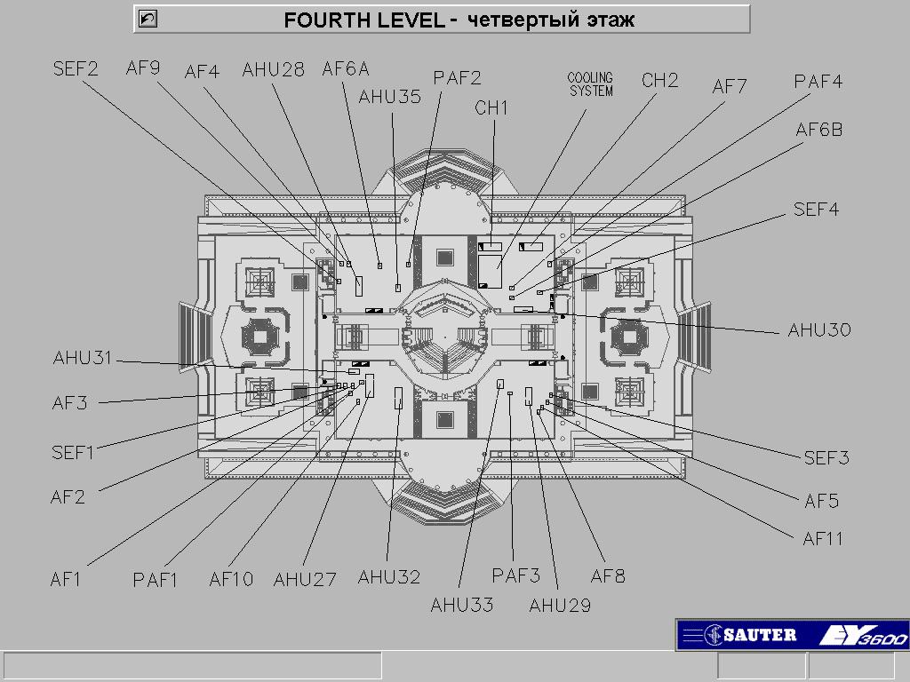
11 11 / 13 Fig. 4 Fig. 5


12 12 / 13 For the monitoring of the individual air-handling units, the structure of the machine as well as the relevant reference points such as sensors and triggers were accurately mapped. This makes it easy for the maintenance staff to interpret the visualised information on the graphic screen (Fig. 6). Fig. 6 Information boxes are shown for the electrical and safety systems. These boxes use dynamic displays to indicate the status of the switches, alarm statuses and electrical variables (Fig. 7). Fig. 7 Fig. 7
13 13 / 13 Company brand names Cooling groups: Heat exchangers with plates: Air-handling units: Extraction fans: Convectors: Base plates: Air distribution ducts: Distribution diffusers: Spiral diffusers: Pumps: Building automation: Water treatment: CLIMAVENETA FIORINI COVENCO INTERNATIONAL FRANCE AIR TRANE RDZ P3 Ductal FRANCE AIR FRANCE AIR DAB SAUTER CULLIGAN Our thanks go to Mr Sandro Mansutti of R.C. Impianti (Udine) for his co-operation. He supplied the technical documentation for this article.
SECTION SEQUENCE OF OPERATIONS FOR HVAC CONTROLS
 SECTION 23 09 93 SEQUENCE OF OPERATIONS FOR HVAC CONTROLS PART 1 - GENERAL 1.1 SUMMARY A. This Section includes control sequences for HVAC systems, subsystems, and equipment. B. See Division 23 Section
Job Name Control Systems Description Date
 Job Name Control Systems Description Date Project Overview The project is a describe the building and its major HVAC systems (e.g. three-story office building, served by a rooftop unit VAV system ). In
RVP310. Heating Controller. Building Technologies HVAC Products
 2 475 Heating Controller RVP310 Multifunctional heating controller for use in residential and non-residential buildings; suitable for weather-dependent flow temperature control of heating zones with or
SECTION SEQUENCE OF OPERATIONS FOR HVAC CONTROLS
 PART 1 - GENERAL SECTION 23 09 93 SEQUENCE OF OPERATIONS FOR HVAC CONTROLS 1.1 SUMMARY A. This Section includes control sequences for HVAC systems, subsystems, and other equipment. B. See Division 23 Section
Heating and D.h.w. Controller RVL482 Basic Documentation
 Heating and D.h.w. Controller RVL482 Basic Documentation Edition: 1.0 Controller series: A CE1P2542en 20.05.2008 Building Technologies Siemens Switzerland Ltd Building Technologies Group International
FUNCTIONAL DESIGN SPECIFICATION
 Issue Date: Issued To: Revision: FUNCTIONAL DESIGN SPECIFICATION Specification Number: SP-XXXX Company Name Signature Date Issued By: Manutec Ltd. Approved By: Approved By: Approved By: Approved By: Authorised
FCCP 200: Fume-cupboard indicator and monitor
 Product data sheet 3.1 43.170 FCCP 200: Fume-cupboard indicator and monitor How energy efficiency is improved Display and interface for safe, energy-efficient monitoring of fume cupboards, pressure zones
PRODUCT DATA COMPACT P - SERIES BY NILAN. Sanitary hot water production. Heating. Ventilation < 300 m 3 /h. Passive heat recovery.
 PRODUCT DATA COMPACT P - SERIES BY NILAN Domestic Passive heat recovery Active heat recovery Ventilation < 300 m 3 /h Comfort heating Comfort cooling Sanitary hot water production Heating THE VENTILATION
Virginia Tech Standards for Building Automation System
 March 1, 2016 Virginia Tech Standards for Building Automation System A. Existing Conditions: The Campus Building Automation System is Siemens Apogee and controls all significant campus facilties. Virginia
A. Base Bid: 1. Heating Contractor provide: a. Control sequences for HVAC systems, subsystems, and equipment.
 SECTION 23 09 93 - SEQUENCE OF OPERATIONS FOR HVAC CONTROLS PART 1 - GENERAL 1 WORK INCLUDES A. Base Bid: Heating Contractor provide: Control sequences for HVAC systems, subsystems, and equipment. B. Alternate
RVL471 Heating and Domestic Hot Water Controller Basic Documentation
 RVL471 Heating and Domestic Hot Water Controller Basic Documentation Edition: 2.2 Controller series: C CE1P2524E 23.10.2002 Siemens Building Technologies HVAC Products 2/118 HVAC Products 23.10.2002 Contents
RVL480. Heating Controller
 2 540 Heating Controller RVL480 Multifunctional and communicating heating controller for use in residential and non-residential buildings. Suited for heating circuit control, boiler temperature control
Master devices. Type X-AIR-ZMAS. Zone master module for up to 25 zone modules, with integral webserver and interfaces to higher-level systems
 X X testregistrierung Type Web server, also for mobile devices Zone modules Zone master module for up to 25 zone modules, with integral webserver and interfaces to higher-level systems X-AIRCONTROL zone
RVL472. Heating Controller. Building Technologies HVAC Products. Series C. including d.h.w. heating
 2 526 Heating Controller including dhw heating Series C RVL472 Multifunctional heating controller for use in residential and non-residential buildings Suited for: Heating zone control with or without room
UNIFIED FACILITIES GUIDE SPECIFICATIONS
 USACE / NAVFAC / AFCEC / NASA UFGS-23 09 93 (November 2015) ----------------------------- Preparing Activity: USACE Superseding UFGS-23 09 23 (May 2011) UNIFIED FACILITIES GUIDE SPECIFICATIONS References
Zone. In the. Contractors and technicians may often find themselves. In today s wired world, zoning has evolved from wired to wireless.
 In the Zone How zoning is changing the way contractors do business. B y J o r d a n B r a n d e s a n d L o r i K a s a l l i s All images courtesy of Jackson Systems LLC. 12 RSES Journal SEPTEMBER 2013
RVL470. Heating Controller. Use. Functions. Series B
 2 522 Heating Controller Series B RVL470 Multifunctional heating controller for use in residential and non-residential buildings; suitable for weather-dependent flow temperature control of heating zones
RVL471. Heating controller. G2524en. Installation Instructions. 1 Installation. 2 Commissioning
 G2524en Heating controller Installation Instructions RVL471 1 Installation 1.1 Place of installation In a dry room, e.g. the boiler room Mounting choices: In a control panel (on the inner wall or on a
39HX. High-efficiency dual-flow air handling unit PRODUCT SELECTION DATA. Plug & play unit (built-in control) Class A+ across entire range
 Class A+ across entire range") PRODUCT SELECTION DATA Plug & play unit (built-in control) Class A+ across entire range Classic/Vertical/ceiling-mounted dualflow units High-efficiency heat recovery unit High performance plug fan High-efficiency
PRODUCT SELECTION DATA Plug & play unit (built-in control) Class A+ across entire range Classic/Vertical/ceiling-mounted dualflow units High-efficiency heat recovery unit High performance plug fan High-efficiency
CHAPTER 4. HVAC DELIVERY SYSTEMS
 CHAPTER 4. HVAC DELIVERY SYSTEMS 4.1 Introduction 4.2 Centralized System versus Individual System 4.3 Heat Transfer Fluids 4.4 CAV versus VAV Systems 4.5 Common Systems for Heating and Cooling 4.6 Economizer
RVL481. Heating Controller. including d.h.w. heating
 2 541 Heating Controller including d.h.w. heating RVL481 Multifunctional and communicating heating controller for use in residential and non-residential buildings. Suited for heating circuit control with
Corrigo E. Second generation which contains all applications and languages
 revision 05 2009 Corrigo E Second generation which contains all applications and languages The controllers in the Corrigo E series are intended for applications within heating, boiler and ventilation control
SECTION SEQUENCE OF OPERATIONS FOR BUILDING CONTROLS
 PART 1 GENERAL 1.01 SECTION INCLUDES SECTION 23 0993 SEQUENCE OF OPERATIONS FOR BUILDING CONTROLS A. This section defines the manner and method by which controls function. Requirements for each type of
RVP331. Heating Controller for 2 heating circuits, d.h.w. and boiler. Building Technologies HVAC Products
 2 478 Heating Controller for 2 heating circuits, d.h.w. and boiler RVP331 Multi-functional heating controller for use in residential and non-residential buildings Suitable for weather-compensated flow
EXcon zone control. Control for up to 4 individual zones _ fm. EXHAUSTO A/S Odensevej 76 DK-5550 Langeskov
 3005925_2018-02-05.fm EXcon zone control Control for up to 4 individual zones EXHAUSTO A/S Odensevej 76 DK-5550 Langeskov Tel. +45 65 66 12 34 Fax +45 65 66 11 10 exhausto@exhausto.dk www.exhausto.dk OJ-Air2
Heating Controller for 2 heating circuits, d.h.w. and boiler, communicating
 2 477 Heating Controller for 2 heating circuits, dhw and boiler, communicating RVP330 Multi-functional heating controller for use in residential and non-residential buildings Suitable for weather-compensated
Museum of Bavarian History Regensburg, Germany
 Museum of Bavarian History Regensburg, Germany Dipl.-Ing. Raphaël Vibert, Herz & Lang GmbH Key Facts Client: Public building authorities of Regensburg Architect: Wörner Traxler Richter Planungsgesellschaft
ENERGY LIGHT USER S GUIDE ENERGY LIGHT USER S GUIDE
 ENERGY LIGHT USER S GUIDE Release January 2001 CONTENTS 1.0 GENERAL CHARACTERISTICS... 4 1.1 MAIN CHARACTERIS TICS... 4 2.0 USER INTERFACE (CODE C5121230)... 5 2.1 DISPLAY... 5 2.2 MEANING OF THE LEDS...
SECTION SEQUENCE OF OPERATION FOR HVAC CONTROLS PART 1 GENERAL
 SECTION 15910 SEQUENCE OF OPERATION FOR HVAC CONTROLS PART 1 GENERAL 1.1 RELATED DOCUMENTS A. Drawings and general provisions of the Contract, including General and Supplementary Conditions and other Division
Retrocommissioning Findings Summary: Building X #1 Priority: Major Comfort/Control Problems
 IMPORTANT NOTICE: This sample document is provided for instructional purposes only. CCC is not rendering advice concerning any commission project or practices. This document is neither approved nor intended
DX-9100 Applications from Engineering Services
 System 9100 Technical Manual 636.4 Application Examples Section Technical Bulletin Issue Date 0896 DX-9100 Applications from Engineering Services Introduction Page 3 Overview 3 Air Handling Unit Applications
MECHANICAL SERVICES 101. Ian White
 MECHANICAL SERVICES 101 Ian White Contents 1. Ventilation 2. Heat Gains & Losses 3. Heating Ventilation Air Conditioning (HVAC) Systems What are Building Services Building Services incorporate all aspects
G a
 G2474 74 319 0081 0 a en Installation Instructions Heating controllers RVP3... Installation Place of installation In a dry room, e.g. in the boiler room Mounting choices: Control cabinet (in the front,
Corrigo E Ventilation
 Corrigo E Ventilation Modbus communication guide Contains the most commonly used variables. Covers all versions of Corrigo E Ventilation from 3.2 The challenger in building automation Revision: 2 Date:
1080 Marina Village Parkway, Suite 501 Alameda, CA (510) Fax (510) HVAC DESIGN INTENT
 Fax (510) HVAC DESIGN INTENT") Taylor Engineering 1080 Marina Village Parkway, Suite 501 Alameda, CA 94501-1142 (510) 749-9135 Fax (510) 749-9136 LLC HVAC DESIGN INTENT PART 1 - GENERAL 1.1 Overview A. The project consists of a 3-story
Taylor Engineering 1080 Marina Village Parkway, Suite 501 Alameda, CA 94501-1142 (510) 749-9135 Fax (510) 749-9136 LLC HVAC DESIGN INTENT PART 1 - GENERAL 1.1 Overview A. The project consists of a 3-story
PRODUCT DATA COMFORT 450 BY NILAN. Ventilation & passive heat recovery. Passive heat recovery. < 450 m 3 /h
 PRODUCT DATA COMFORT 40 BY NILAN Ventilation & passive heat recovery Domestic Passive heat recovery Ventilation < 40 m /h COMFORT 40 Product description The Comfort 40 is an energy-efficient ventilation
BES-TECH TECHNOLOGY & SYSTEM INTEGRATION
 BES-TECH TECHNOLOGY & SYSTEM INTEGRATION BES-TECH TECHNOLOGY & SYSTEM INTEGRATION DIGI-ACC Digi-ACC is a control kit for air cooled chiller systems, optimizing both chiller and pumps thereby reducing consumption
Application Manual LT-6617 Rev. 1 July 2017
 Application Manual LT-6617 Rev. 1 July 2017 Table of Contents 1.0 Frequently Asked Questions 4 2.0 OpenBAS Wiring Guidelines 6 3.0 Wiring 9 4.0 Glossary 11 3 1.0 Frequently Asked Questions 1.1 What is
Centrifugal air heaters hot water or electrical supply
 The economical solution with centralised production Individual adjustment in each room The most silent electric air heater to protect against frost or to heat large spaces A wide range of accessories Range:
PRODUCT DATA COMFORT 5000 BY NILAN. Ventilation & passive heat recovery. Passive heat recovery. < 5300 m 3 /h
 PRODUCT DATA COMFORT 5000 BY NILAN Ventilation & passive heat recovery Commercial Passive heat recovery Ventilation < 5300 m 3 /h COMFORT 5000 The Comfort 5000 is a ventilation unit suitable for central
RE: Phase 2 Improvements DATE: July 1, 2016 New Administration Building Wernle Youth & Family Treatment Center 2000 Wernle Road Richmond, Indiana
 ADDENDUM NO. 2 RE: Phase 2 Improvements DATE: July 1, 2016 New Administration Building Wernle Youth & Family Treatment Center 2000 Wernle Road Richmond, Indiana TO: All Bidders Gentlemen: This Addendum
heat interface units A BOILER WITHOUT A FLAME
 A BOILER WITHOUT A FLAME heat interface units Communal Heat Networks A central boiler house will generate heat which is distributed through a network of pipe to each home or apartment in the building.
The integral solution for. Air Handling Units. Technology & Evolution
 The integral solution for Air Handling Units Technology & Evolution For over 25 years Carel has been dealing with the design and production of electronic controllers and supervision systems for Air-Conditioning
LYNX CE CENTRAL CONTROL FOR OSMAC. General Specifications
 LYNX CE CENTRAL CONTROL FOR OSMAC General Specifications Number of satellites: Up to 255 Number of satellite stations: up to 16,320 Number of Courses: 3 Number of holes per course: 48 Number of holes per
Roof top SPACE RPC 450Z R407C M011
 Roof top SPACE RPC 450Z R407C M011 Page : 1 / 5 Independant roof mounted unit, cooling only, ready to be installed, designed for air conditioning of large volumes for industrial or commercial use. As per
District heating controller for two heating circuits and d.h.w. according to Siemens specifications:
 4 319 2984 0 G2384en en Installation Instructions District heating controller for two heating circuits and d.h.w. RVD240 Installation Place of installation In a dry room, e.g. in the heat exchanger room
Automatic control system. for kitchen facilities
 EN for kitchen facilities FUNCTIONS AND ADVANTAGES The system of automatic kitchen ventilation control is an optional accessory available for ATREA s cooker hoods and ventilation and air-conditioning ceilings.
2. CURRICULUM. Sl. No.
 . CURRICULUM Sl. No. Code Title No. of Lecture Hours 1 RAC 001 Fundamentals of Refrigeration and Air 60 conditioning RAC 00 Psychrometry, Heat load Estimation for 70 Air conditioning and Refrigeration
Hello, my name is Audra Benzschawel and I m a marketing engineer in the C.D.S. Slide 1 TRACE 700
 Slide 1 TRACE 700 Unmet Load Hours Hello, my name is Audra Benzschawel and I m a marketing engineer in the C.D.S. group at TRANE. Today I will be talking about unmet hours. What are they, common causes,
Automation System TROVIS 5400 Ventilation Controller TROVIS Mounting and Operating Instructions EB 5477 EN. Electronics from SAMSON
 Automation System TROVIS 5400 Ventilation Controller TROVIS 5477 ounting and Operating Instructions Electronics from SASON EB 5477 EN Firmware version 2.0x Edition April 2004 Disclaimer of liability Disclaimer
Flexible & Innovative. Cooling Solutions
 Flexible & Innovative Cooling Solutions Flexible & Innovative Compu-Aire Inc. offers a variety of high performance precision cooling systems that can adapt to your application needs. With today s rapidly
GARCIA GALUSKA DESOUSA Consulting Engineers
 L#57295/Page 1/July 21, 2017 HVAC SYSTEMS NARRATIVE REPORT The following is the HVAC system narrative, which defines the scope of work and capacities of the HVAC system as well as the Basis of Design.
Installer Manual KNX Touchscreen Thermostat
 Installer Manual 02952 KNX Touchscreen Thermostat Index GENERAL FEATURES AND FUNCTIONALITY from page 5 ETS PARAMETERS AND COMMUNICATION OBJECTS from page 7 COMMUNICATION OBJECTS GENERAL FEATURES AND FUNCTIONALITY
AIR-CONDITIONING SYSTEMS AND APPLICATIONS. Abdullah Nuhait Ph D. King Saud University
 AIR-CONDITIONING SYSTEMS AND APPLICATIONS Abdullah Nuhait Ph D. King Saud University AIR-CONDITIONING SYSTEMS Earliest air conditioning system used only for heating (winter) Provided heated air for comfort
PRODUCT DATA COMBI 300 POLAR BY NILAN. Ventilation with passive & active heat recovery. Active heat recovery. Passive heat recovery.
 PRODUCT DATA COMBI 300 POLAR BY NILAN Ventilation with passive & active heat recovery Domestic Passive heat recovery Active heat recovery Ventilation < 350 m 3 /h Comfort heating Comfort cooling COMBI
4. OVERVIEW OF MECHANICAL SYSTEM
 4. OVERVIEW OF MECHANICAL SYSTEM The 87,000 SF SLCC is served by six (6) Trane M-Series Climate Changer Air Handing Units (AHUs). Each unit serves a distinct zone within the facility that is unique in
SPECIFICATION GUIDE FLEXAIR. Possibility to add auxiliary heaters: Gas, Electrical Heater, Hot Water Coil Possibility to add Heat Recovery Module
 SPECIFICATION GUIDE FLEXAIR Air-cooled packaged Rooftop unit Cooling only or Heat Pump Nominal cooling capacity: 85 to 234 kw Nominal heating capacity: 83 to 226 kw Possibility to add auxiliary heaters:
Appendix 13. Categories of Cooling and Heating systems
 EcoShopping - Energy efficient & Cost competitive retrofitting solutions for Shopping buildings Co-funded by the European Commission within the 7 th Framework Programme. Grant Agreement no: 609180. 2013-09-01
At Coster we manufacture a comprehensive range of pre confi gured modular controllers which are both easy to install and simple to programme by use
 At Coster we manufacture a comprehensive range of pre confi gured modular controllers which are both easy to install and simple to programme by use of 4 operating keys and an alphanumeric display. When
GA01HC-02. Service manual. Room Panel. Programme version 01a. Operating with GH07EA regulator for controlling electrode boilers
 Room Panel GA01HC-02 Operating with GH07EA regulator for controlling electrode boilers Programme version 01a Service manual We request that users carefully study applicable Instructions before connecting
CRIMSON & CRIMSON MAX
 High efficiency water/water and geothermal heat pumps 5 114 General High efficiency water/water and geothermal heat pumps. Ideal for heating, cooling and production of domestic hotwater with total or partial
Securing the operational readiness of fire control systems
 CFPA-E No 23:2010 F Securing the operational readiness of fire control systems CFPA-E -GUIDELINES EFSAC Endorsed FOREWORD The European fire protection associations have decided to produce common guidelines
OPERATION MANUAL. Daikin Altherma indoor unit EKHVMRD50ABV1 EKHVMRD80ABV1 EKHVMYD50ABV1 EKHVMYD80ABV1
 OPERATION MANUAL EKHVMRD50ABV1 EKHVMRD80ABV1 EKHVMYD50ABV1 EKHVMYD80ABV1 EKHVMRD50+80ABV1 EKHVMYD50+80ABV1 CONTENTS Page 1. Definitions... 1 2. Introduction... 2 2.1. General information... 2 2.2. Scope
Case Study 1 Underground Car Park
 Case Study 1 Underground Car Park Dorota Brzezińska 1, Janusz Paliszek 2, Piotr Smardz 2, Renata Ollesz 1, Karol Kaczor 2 1 Lodz University of Technology, GRID - Lodz, 2 INBEPO Wroclaw, Poland Building
1 Air Handling Units In ICE
 1 Air Handling Units In ICE From version 3.0, there is a library of common air handling units (AHU) in the distribution. A simulated building can have several AHUs. The following limitations apply: - every
CLIMA I Thermostat ZENNIO
 ZENNIO CLIMA CLIMA I Thermostat ZENNIO Edition 2 INTRODUCTION INDEX 1. INTRODUCTION... 3 2. DEVICES WITH THERMOSTAT... 5 3. THERMOSTAT CONFIGURATION... 7 3.1. TYPE OF CONTROL... 7 3.1.1. 2 POINTS WITH
CT EN rel. 10/09 Copyright Eliwell Controls s.r.l All rights reserved
 Eliwell Controls Srl Via dell Industria, 15 Z. I. Paludi 32010 Pieve d Alpago (BL) - Italy Telephone +39 0437 986 111 Facsimile +39 0437 989 066 Sales: +39 0437 986 100 (Italy) +39 0437 986 200 (other
VERSO DOMEKT. Residential ventilation units m³/h. Non residential ventilation units m³/h
 VENTILATION equipment VENTILATION equipment content DOMEKT Residential ventilation units 50 1 000 m³/h 15 VERSO Non residential ventilation units 1000 34 000 m³/h 61 Domekt R 17 Domekt R 200 V 19 Domekt
M.A.R.V.E.L. Intelligent Demand Controlled Ventilation System for Professional Galleys. Enabling Wellbeing
 M.A.R.V.E.L. Intelligent Demand Controlled Ventilation System for Professional Galleys Enabling Wellbeing M.A.R.V.E.L. revolutionises energy footprint in galleys The M.A.R.V.E.L.* is the first truly intelligent,
opti-visor ultra-efficient chiller plant automation Typical specification
 opti-visor ultra-efficient chiller plant automation Typical File No: 90.893 Date: february 9, 2015 Supersedes: 90.893 Date: april 20, 2012 contents 1.0 Chilled water plant 4 1.1 General system requirements
BRAN Residential chillers and heat pumps. Reversible unit, air source for outdoor installation 4,81-27,2 kw <<< BACK INDEX.

LMV52 Control. Specifications. Document No. LV February 3, Product Description. Sample Specification
 LMV52 Control Product Description February 3, 2017 The LMV52 is a microprocessor-based burner management system with matching system components for the control and supervision of forced draft burners.
CARRIER edesign SUITE NEWS. Modeling 100% OA Constant Volume Air Systems. Volume 6, Issue 1. Page 1 Modeling 100% OA Constant Volume Air Systems
 Volume 6, Issue 1 CARRIER edesign SUITE NEWS Modeling 100% OA Constant Volume Air Systems This article provides an overview of how to model a stand-alone constant air volume (CAV) 100% OA system in HAP.
DAIKIN Air Handling Unit Modular
 DAIKIN Air Handling Unit Modular Compact ventilation unit with heat recovery Energy efficiency and air quality Daikin air handling units, with their plug-and-play design and inherent flexibility, can be
> HGA AIR - WATER HEAT PUMPS FOR OUTDOOR INSTALLATION. Available range. Unit description. Options. Accessories
 > HGA AIR - WATER HEAT PUMPS FOR OUTDOOR INSTALLATION Available range Unit type IP Reversible heat pump (reversible on the refrigerant side) ECO-FRIENDLY REFRIGERANT GAS Versions (heat recovery) VB Base
MicroTech Rooftop/RMC
 Open Protocol Data Communications Packet Version 4.1 Group: Controls Date: March 1999 MicroTech Rooftop/RMC Data Information Packet for Open Protocol 1999 McQuay International Revision History Version
ETA ACCU 90% HIGHEST EFFICIENCY AIR HANDLING UNIT
 90% EFFICIENCY HIGHEST EFFICIENCY AIR HANDLING UNIT Packaged energy recovery solutions for Green Buildings Integrated Accumulator, controls and DX Cooling System CLEAN AIR SINCE 1963 Euroclima is a company
AL-KO CONTROL TECHNOLOGY THE SIMPLE ROUTE TO CONTROL
 AL-KO Web control configurator HVAC with control AL-KO control technology (ART) sets the new standard in control technology for central ventilation systems. Clearly structured and coordinated precisely
Technical Assignment 3 11/15/04. Executive Summary
 Executive Summary This report is an analysis of the existing systems within the Outreach Innovation Building in University Park, PA. One significant design criteria was a lower than average noise criteria
A full list of energy conservation opportunities (ECO) for air-conditioned buildings
 for air-conditioned buildings") A full list of energy conservation opportunities (ECO) for air-conditioned buildings Team France (Project coordinator) Armines - Mines de Paris Austria Austrian Energy Agency Belgium Université de Liège
A full list of energy conservation opportunities (ECO) for air-conditioned buildings Team France (Project coordinator) Armines - Mines de Paris Austria Austrian Energy Agency Belgium Université de Liège
Reference Guide for Microprocessor Controller
 Document 483586 Microprocessor Controller for Dedicated Outdoor Air System Reference Guide for Microprocessor Controller Please read and save these instructions for future reference. Read carefully before
LYNX SE CENTRAL CONTROL FOR NETWORK GDC. General Specifications
 LYNX SE CENTRAL CONTROL FOR NETWORK GDC General Specifications Number of Gateways: Up to 4, each with up to 2 Station Groups Number of decoder stations: up to 500 Number of Courses: 1 Number of holes per
PLAN REVIEW SUBMITTAL GUIDE
 PLAN REVIEW SUBMITTAL GUIDE Plans, specifications and other construction documentation for the initial plan review should be as complete as possible at the time of submittal. Use this convenient guide
Climate control precision in Hi-tech environments Jupiter and Mercury Close Control Units
 Climate control precision in Hi-tech environments Jupiter and Mercury Close Control Units Precision control from the total provide Uncompromised precision More than ever data centers, server rooms, and
PRODUCT DATA COMFORT 1200 BY NILAN. Ventilation & passive heat recovery. Passive heat recovery. < 1400 m 3 /h
 PRODUCT DATA COMFORT 00 BY NILAN Ventilation & passive heat recovery Commercial Passive heat recovery Ventilation < 00 m /h COMFORT 00 The Comfort 00 is a ventilation unit suitable for central ventilation
PRODUCT DATA COMFORT 600 BY NILAN. Ventilation & passive heat recovery. Passive heat recovery. < 800 m 3 /h
 PRODUCT DATA COMFORT 00 BY NILAN Ventilation & passive heat recovery Domestic Passive heat recovery Ventilation < 800 m /h COMFORT 00 Product description The Comfort 00 is an energy-efficient ventilation
incorporating Guidance to Shafts for Smoke Control A useful guide to practical smoke shaft principals and specifications
 incorporating Guidance to Shafts for Smoke Control A useful guide to practical smoke shaft principals and specifications Smoke shafts - an overview Scope of this guide Smoke shaft is the common term for
Daikin Applied UK Technically better... D-AHU Modular R. Air handling units. Compact air handling unit with heat recovery wheel
 Daikin Applied UK Technically better... D-AHU Modular R Air handling units Compact air handling unit with heat recovery wheel Energy efficiency and air quality With their Plug & Play design and inherent
Element Z General Design Requirements Existing Facilities Information
 Charles M. LeMaistre PART 1 - INTRODUCTION 1.01 OVERVIEW A. This Section provides general information for building systems and components. B. Refer to the Owner s Design Guideline Elements A though G and
OPERATION MANUAL. Packaged air-cooled water chillers and packaged reversible air to water heatpumps EWAQ009ACV3 EWAQ010ACV3 EWAQ011ACV3
 OPERATION MANUAL Packaged air-cooled water chillers and packaged reversible air to EWAQ009ACV3 EWAQ010ACV3 EWAQ011ACV3 EWYQ009ACV3 EWYQ010ACV3 EWYQ011ACV3 EWAQ009ACW1 EWAQ011ACW1 EWAQ013ACW1 EWYQ009ACW1
N M AirControl AHU. Control manual
 N 10.63 M 03-2016 AirControl AHU Control manual EN CONTENTS PAGE 1 - MONITORING AND CONTROL 2 1.1 The program 2 1.2 The HMI terminal 2 1.3 The controller 4 1.4 Description of the air handling units 4
The Creative and Performing Arts High School (CAPA) Pittsburgh, PA 11/11/2002 Andrew Tech Mechanical Option Prof. S. A. Mumma
 Pittsburgh, PA 11/11/2002 Andrew Tech Mechanical Option Prof. S. A. Mumma") Objectives and Requirements For the Creative and Performing Arts High School (CAPA), the main objective of the mechanical design is to provide an energy efficient system that is easily maintainable and
Objectives and Requirements For the Creative and Performing Arts High School (CAPA), the main objective of the mechanical design is to provide an energy efficient system that is easily maintainable and
RVP360 and RVP361 Heating controllers for 2 heating circuits and d.h.w. Basic Documentation
 RVP360 and RVP361 Heating controllers for 2 heating circuits and d.h.w. Basic Documentation Edition 1.0 Controller series A CE1P2546en 15.03.2011 Building Technologies Siemens Switzerland Ltd Industry
THIS IS A DESIGN GUIDE NOT A SPECIFICATION. Montgomery County Public Schools Facilities Guide DIVISION 15 MECHANICAL
 SECTION 15100 PART 1 GENERAL THIS IS A DESIGN GUIDE NOT A SPECIFICATION Montgomery County Public Schools Facilities Guide DIVISION 15 MECHANICAL HVAC SYSTEMS APPLICATIONS 1.1 SCOPE: The intent of this
COMcheck Software Version Mechanical Compliance Certificate
 COMcheck Software Version 4.0.8.1 Mechanical Compliance Certificate Project Information Energy Code: Location: Climate Zone: Project Type: 90.1 (2013) Standard Buda, Texas 2a New Construction Construction
Measurement and modelling of a multifunctional solar plus heatpump system from Nilan. Experiences from one year of test operation.
 Measurement and modelling of a multifunctional solar plus heatpump system from Nilan. Experiences from one year of test operation. Bengt Perers 1, Elsa Andersen 2, Simon Furbo 2, Ziqian Chen 2 and Agisilaos
Save energy while maintaining a constant room climate
 The worldwide standard for home and building control Save energy while maintaining a constant room climate Room thermostats that maximize control accuracy for heating, ventilation and air conditioning
OACS Outdoor Air-Cooled Central Chillers
 OACS Outdoor Air-Cooled Central Chillers Proudly Made In The USA since 1977 A Complete Central Chiller System Complete Central Chiller system with Integrated Reservoir and Pump all mounted on a single
RVL479. Heating Controller. for use with a partner unit
 2 543 Heating Controller for use with a partner unit RVL479 Communicating heating controller for use in residential and non-residential buildings. For exclusive use on the bus together with heating controllers
Redesign of Bennett Hall HVAC System
 MEE 488 April 18, 2006 Redesign of Bennett Hall HVAC System Greg Andreasen Michael Chicoine Florent Hohxa Jason Jacobe Mechanical Engineering, University of Maine, Orono ME 04473, USA ABSTRACT Our task