Installation and Service Manual
|
|
|
- Britton Sims
- 5 years ago
- Views:
Transcription


")

1 Installation and Service Manual ATW-Series Reversing Air to Water Heat Pump Two-Stage R410a Model Sizes Maritime Geothermal Ltd. P.O. Box 2555, 170 Plantation Road Petitcodiac, NB E4Z 6H4 (506) ISSUE Page Aug ECO Jul-2017
2 SAFETY PRECAUTIONS WARNING: Ensure all access panels are in place and properly secured before applying power to the unit. Failure to do so may cause electrical shock. WARNING: Before performing service or maintenance on the heat pump system, ensure all power sources are DISCONNECTED. Electrical shock can cause serious personal injury or death. WARNING: Heat pump systems contain refrigerant under high pressure and as such can be hazardous to work on. Only qualified service personnel should install, repair, or service the heat pump. CAUTION: CAUTION: Safety glasses and work gloves should be worn at all times whenever a heat pump is serviced. A fire extinguisher and proper ventilation should be present whenever brazing is performed. Venting refrigerant to atmosphere is illegal. A proper refrigerant recovery system must be employed whenever repairs require removal of refrigerant from the heat pump. Model Nomenclature ATW 65 HACW P 1T C xx Series: ATW = Active Cooling Air to Liquid Nominal Size: 25 = 020 compressor 45 = 030 compressor 55 = 040 compressor 65 = 051 compressor 75 = 060 compressor 80 = 067/070 compressor Functions: H = Heating AC = Active Cooling W = Domestic Hot Water Refrigerant: P = R410a Revision: 01, 02 etc. Indoor Loop Exchanger: C = Copper Y = CuNi coil & piping Z = CuNi coil only Compressor: S = 1 Stage Scroll T = 2 Stage Scroll Voltage Code: 1 = VAC 2 = VAC 4 = VAC 6 = VAC 7 = VAC Page 2
3 APPLICATION TABLE SIZE FUNCTION REFRIGERANT VOLTAGE COMPRESSOR STAGES* INDOOR COIL REVISIONS 25 HACW P T C Y Z HACW P T C Y Z HACW P T C Y Z HACW P T C Y Z HACW P T C Y Z 02 6 S This manual applies only to the models and revisions listed in this table FIRMWARE AND PC APP APPLICATION TABLE Firmware Version* Associated PC APP Version MGT GEN2 Bootload Firmware V2.49Rx MGT GEN2 PC APP V1.19 MGT GEN2 Bootload Firmware V2.48Rx MGT GEN2 PC APP V1.18 MGT GEN2 Bootload Firmware V2.47Rx MGT GEN2 PC APP V1.17 * x may be any number from 1 to 9. There may not be an Rx, ie simply V2.49 Maritime Geothermal Ltd. has a continuous improvement policy and reserves the right to modify specification data at any time without prior notice. Page 3
4 Table of Contents Tables, Figures, & Documents... 5 Installation Basics... 6 Unit description... 6 Unpacking the unit... 6 Optimum Placement... 6 Electrical Connections... 6 DIAGRAM A - Heat Pump Connections... 6 Control Transformer... 7 Indoor Loop Circulator Pump Wiring... 7 Outdoor Unit Power Supply... 7 Outdoor Unit Signal Connections Setpoint Control Hardwired Control CDG - Typ. ATW Series Wiring CDG - Typ. Heating Only Zone Wiring (Setpoint) CDG - Typ. Htg/Cooling Zone Wiring (Setpoint) CDG - Typ. Htg Only Zone Wiring (Hardwired) CDG - Typ. Htg/Cooling Zone Wiring (Hardwired) Indoor Loop Water Lines Domestic Hot Water (Desuperheater) Connections PDG - Connection to DHW Pre-Heat Tank PDG - Typical Loop Connections - ATW Series PDG - Typical Buffer Tank Configuration: 4 port PDG - Typical Buffer Tank Configuration: 2 port Sample Bill of Materials - ATW Series Outdoor Unit (ACE) Installation Outdoor Unit Description Outdoor Unit Location Outdoor Unit Mounting Height DIAGRAM B - Leg Kit Installation Outdoor Unit Wiring DIAGRAM C - Average Maximum Snow Depth - Canada Outdoor Line Set Connection & Charging Line Set Interconnect Tubing Oil Traps Pipe Insulation Silver Soldering Line Sets Pressure Testing Vacuuming The System Charging The System CDG - Typical ATW Line Set Connections Sizing & Hydronic Installation Heat Pump Sizing Hydronic Systems PDG - Typical Zone Types System Operation General Overview Heating Operation Cooling Operation Defrost Operation PC Application (PC App) PC Application Menus BACnet Interface Startup Procedure Pre-start Inspection Unit Startup Startup Record General Maintenance Troubleshooting Guide Troubleshooting Tools Repair Procedures Model Specific Information Shipping Information Refrigerant Charge Indoor Loop Flow Rates Operating Temperature Limits Outdoor Unit Sound Levels Indoor Unit Sound Levels Indoor Loop Pressure Drop Data Standard Capacity Ratings Performance Tables: ATW Performance Tables: ATW Performance Tables: ATW Performance Tables: ATW Performance Tables: ATW Electrical Tables Wiring Diagram (208/ ) Electrical Box Layout (208/ ) Wiring Diagram ( ) Electrical Box Layout ( ) Wiring Diagram ( ) Electrical Box Layout ( ) ATW Refrigeration Circuit - Heating Mode ATW Refrigeration Circuit - Cooling Mode Dimensions: ATW-25/ Dimensions: ATW Dimensions: ATW-65/ Appendix A: Control Board Description Appendix B: PC Software Installation Appendix C: USB Driver Setup Appendix D: Updating Firmware Warranty LCD Display & Menus Setpoint Control Indoor Circulator Operation TOP UP S Outdoor Reset Page 4
5 Tables, Figures, & Documents Tables Figures Documents Table 1 - Power Supply Connections (Heat Pump)... 7 Table 2 - Control Transformer... 7 Table 3 - Power Supply Connections (Outdoor Unit)... 7 Table 4 - Outdoor Unit Signal Connections... 7 Table 5 - Setpoint Control Connections... 8 Table 6 - Setpoint Control: Hydronic Auxiliary Connections... 8 Table 7 - Hardwired (Aquastat) Connections... 8 Table 8 - Typical Aquastat Settings... 8 Table 9 - Buffer Tank Size Table 10 - Interconnect Line Set Sizing Table 11 - System Charge Chart Table 12 - Extra Charge Chart (Sizes 25-45) Table 13 - Extra Charge Chart (Sizes 55-75) Table 14 - Heat Pump Size vs. Heated Area Table 15 - Maximum Output Temperature Table 16 - Typical Temperature Settings Table 17 - BACnet Objects - Control Signals (Read/Write) Table 18 - BACnet Objects - Data (Read Only) Table 19 - BACnet Objects - Alarms and Faults (Read Only) Table 20 - Shipping Information - Indoor Unit Table 21 - Shipping Information - Outdoor Unit Table 22 - Refrigerant Charge Table 23 - Indoor Loop Flow Rates Table 24 - Operating Temperature Limits Table 25 - Outdoor Unit Sound Levels (dba) Table 26 - Indoor Unit Sound Levels (dba) Table 27 - Indoor Loop Pressure Drop Data (Water) Table 28 - Standard Capacity Ratings - Heating Table 29 - Standard Capacity Ratings - Cooling Table 30 - Voltage Code 1 (208/ ) Table 31 - Voltage Code 2 ( ) Table 32 - Voltage Code 4 ( ) Table 33 - Voltage Code 6 ( ) Table 34 - Voltage Code 7 ( ) Table 35 - Control Board Connector Descriptions (Top) Table 36 - Control Board Connector Descriptions (Left Side) Table 37 - Control Board Connector Descriptions (Bottom) Table 38 - Control Board Connector Descriptions (Right Side) Diagram A - Heat Pump Connections... 7 Diagram B - Leg Kit Installation Diagram C - Average Maximum Snow Depth - Canada Dimensions: ATW-25/ Dimensions: ATW Dimensions: ATW-65/ CDG - Typical ATW Outdoor Unit, Aux. Heat, & Indoor Circulator Wiring CDG - Typical Zone and Auxiliary Wiring with GEN2 Setpoint Control (Heating Only) CDG - Typical Zone and Auxiliary Wiring with GEN2 Setpoint Control (Heating & Cooling) CDG - Typical Zone and Auxiliary Wiring with GEN2 Hardwired Option (Heating Only) CDG - Typical Zone and Auxiliary Wiring with GEN2 Hardwired Option (Heating & Cooling) PDG - Single Unit Connection to DHW Pre-Heat Tank (Brass FPT) PDG - Typical Loop Connections - ATW Series PDG - Typical Buffer Tank Configuration Four Port Tank (Brass FPT) PDG - Typical Buffer Tank Configuration Two Port Tank (Brass FPT) CDG - Typical ATW to Outdoor Unit Line Set Connections PDG - Typical Zone Types for Hydronic Applications SCH-01 - ATW-**-HACW-P-1*-* Schematic Diagram ELB-01 - ATW-**-HACW-P-1*-* Electrical Box Diagram SCH-01 - ATW-**-HACW-P-2*-* Schematic Diagram ELB-01 - ATW-**-HACW-P-2*-* Electrical Box Diagram SCH-01 - ATW-**-HACW-P-4*-* Schematic Diagram ELB-01 - ATW-**-HACW-P-4*-* Electrical Box Diagram RCD - ATW-Series Refrigeration Circuit Diagram Heating Mode RCD - ATW-Series Refrigeration Circuit Diagram Cooling Mode Page 5
6 Installation Basics Unit Description The ATW-Series unit is a high efficiency two-stage air to water heat pump. When used in conjunction with a secondary source of heat, it may be used as the primary source of heating for whole home comfort down to a minimum outside temperature of -7 F (-21.7 C) at which point the unit will automatically shut down and the secondary source will provide the full heating capacity until the unit is re-enabled by warmer temperatures. Unpacking the Unit When the heat pump reaches its destination it should be unpacked to determine if any damage has occurred during shipment. Any visible damage should be noted on the carrier's freight bill and a suitable claim filed at once. The heat pump is well constructed and every effort has been made to ensure that it will arrive intact, however it is in the customer's best interest to examine the unit thoroughly when it arrives. Optimum Placement For air to water models, the placement of the unit has negligible effect on the operation and efficiency of the system. It is recommended that the unit be placed near where the interconnect piping to the outdoor unit will be to keep the piping distance to a minimum. Electrical Connections The heat pump has several knockouts / holes for the electrical connections, shown in DIAGRAM A. Note that some connections are located on both the front and side of the unit for convenience. A schematic diagram (SCH) and electrical box layout diagram (ELB) can be found inside the electrical box cover of the unit as well as in the Model Specific section of this manual. The Electrical Tables in the Model Specific section and the ELB diagram contain information about the size of wire for the connections, as well as the recommended breaker size. Power supply connections to the unit are made directly to the compressor contactor and are as per TABLE 1. Ground is to be connected to the GND lug inside the electrical box. IMPORTANT NOTE: A properly qualified electrician should be retained for all connections to the heat pump and associated controls. The connections to the heat pump MUST CONFORM TO LOCAL CODES. If possible the access panels should remain clear of obstruction for a distance of two feet to facilitate servicing and general maintenance. Raising the heat pump off the floor a few inches is generally a good practice since this will minimize noise and prevent rusting of the bottom panel of the unit. We recommend that the heat pump be placed on a pad, available from Maritime Geothermal as an accessory, or a piece of 2'' thick styrofoam that will smooth out any irregularities in the cement floor and deaden any compressor noise emitted from the bottom of the cabinet. DIAGRAM A - Heat Pump Connections Page 6
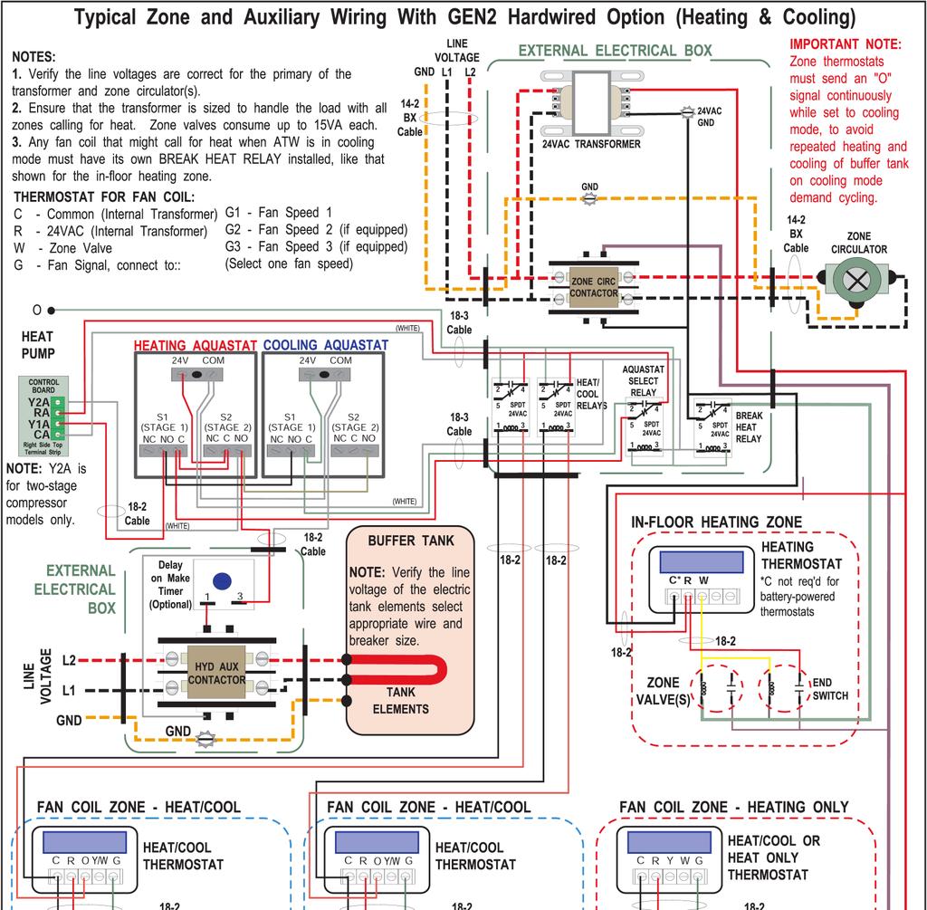
7 TABLE 1 - Power Supply Connections (Heat Pump) Line Description Voltages L1 Line 1 All L2 Line 2 All L3 Line , , N** Neutral 208/ , , GND Ground All (connect to ground lug) ** Only required if connecting 115VAC circulators to the heat pump for 208/ and models, the heat pump itself does not require a neutral. Required for models. Control Transformer The low voltage controls are powered by a 100VA class II transformer. Circuit protection is provided by either a resettable breaker on the secondary side of the transformer or primary and secondary fuses (refer to TABLE 2). Should the breaker trip (or fuse blow), locate and correct the problem and then reset the breaker by pressing in on it (or replace the blown fuse). TABLE 2 - Control Transformer Voltage Low Voltage Circuit Protection (1) 208/ Resettable breaker on transformer (2) Resettable breaker on transformer (4) Primary / Secondary fuses (6) Primary / Secondary fuses (7) Primary / Secondary fuses IMPORTANT NOTE: For 208/230VAC-1-60 units, if connecting to 208VAC power supply move the red wire connected to the 240 terminal of the transformer to the 208 terminal of the transformer. Indoor Loop Circulator Pump Wiring The heat pump has provisions for connecting the circulator pump(s) so that they will be turned on whenever the compressor operates. Connect the circulator pump module to the appropriate two terminals (115VAC or 230VAC) of the terminal strip marked INDOOR CIRCULATORS in the heat pump, as per the voltage of the circulator pump module. Ground wires should be connected to the ground lug in the electrical box. Ensure that the total current draw does not exceed the value indicated on the label in the heat pump electrical box. For 460VAC models, 24VAC and ground are provided on the terminal strip for use with external components to control the circulator(s). Refer to the electrical box drawing on the electrical box cover for more information. Outdoor Unit Power Supply The Outdoor Unit is powered from the ATW unit. The power supply for the Outdoor Unit is 208/ or 220/1/50. The ATW and Outdoor Unit have matching terminal strips for these connections. Connect a two conductor (minimum 14ga) outdoor rated cable between the ATW and the Outdoor Unit. TABLE 3 shows a description of the connections required. Refer to drawing CDG. IMPORTANT NOTE: A disconnect switch visible from the Outdoor Unit must be installed in the power supply cable. If the switch has fuses or breakers they must be no more than 10A MAX. TABLE 3 - Power Supply Connections (Outdoor Unit) Line Description L1 Supply line L2 Supply line GND Ground. Use a two conductor outdoor rated 14ga minimum cable. A disconnect switch (10A MAX) visible from the Outdoor Unit must be installed in the power supply cable. Outdoor Unit Signal Connections The ATW and Outdoor Unit have matching terminal strip signals for these connections. Connect an 8 conductor shielded outdoor rated cable between the terminal strip in the ATW and the terminal strip in the Outdoor Unit. The signals are marked as Outdoor Unit Signals Connections on the ATW terminal strip. The shield ground wire is connected only to the ATW unit, do not connect the shield ground to the Outdoor Unit (there is no terminal for it). Simply cut the shield ground wire short at the cable sheath in the Outdoor Unit. The signals are described TABLE 4. Refer to drawing CDG. TABLE 4 - Outdoor Unit Signal Connections Signal Description EEVR Electronic Expansion Valve (Red) EEVG Electronic Expansion Valve (Green) EEVW Electronic Expansion Valve (White) EEVB Electronic Expansion Valve (Black) TR Outdoor Temperature Sensor (Power) TG Outdoor Temperature Sensor (Signal) TB Outdoor Temperature Sensor (Ground) PWM+ Outdoor Fan Control Shield GND* Shielded cable ground wire * Connect only to the ATW. In the Outdoor Unit, leave this wire unconnected and cut it short at the cable sheath. 1. Setpoint Control NOTE: If controlling the system via the BACnet interface, skip the next two sections, as no connections are required. One of the features of the GEN2 Control Board is built in Aquastat functionality (with optional Outdoor Reset) known as Setpoint Control. Refer to the Setpoint Control section of this manual for more information. It is recommended that this option be used to operate the heat pump system since it eliminates the need for an external aquastat and temperature probe in the tank (s) and provides a three stage system along with delay timer for the hydronic auxiliary heat. Only one external connection is required with this mode of operation, a dry contact from the R to O terminal to switch to cooling mode (see TABLE 5). Note that in cooling mode, it is important to choose zone thermostats or other control devices that continuously send an O signal, even when there is no cooling demand. This is to avoid repeated heating and cooling of the buffer tank on demand cycling, causing temperature lags and high electricity consumption. Drawings CDG and CDG show a typical wiring setup for zones, zone circulator and hydronic auxiliary for heating only and heating /cooling system. Page 7
8 TABLE 5 - Setpoint Control Connections TABLE 7 - Hardwired (Aquastat) Connections Signal Description Signal Description O R Cooling Mode (Reversing Valve) 24VAC hot When using the Setpoint Control method to operate the unit, there are 3 methods for activating hydronic auxiliary heat. The connections are shown in TABLE 6 and drawing CDG. First, a 24VAC control signal on terminal 1A (with CA as ground/common) is available to power the coil of an external contactor in order to operate hydronic auxiliary heat if installed. Choose this method if using a heating device that doesn t have its own electronic controller or control transformer, e.g. a bare heating element in the buffer tank. This signal can provide a maximum of 500mA at 24VAC. Second, a dry contact on terminals D1 and D2 is available, to actuate a heating device that has its own control transformer. In general, these types of devices will have their own electronic temperature controller. Therefore, it will be necessary to disable the on-board temperature control on the external heating device, and adjust its settings so it is only activated by the heat pump s controller. This method should be used for the Thermo2000 EcoUltra tank that is available from Maritime Geothermal as an accessory. Third, a dry contact is available on terminals H1 and H2. It operates similarly to D1/D2 above, but is only activated when auxiliary heat is requested AND the compressor is off (i.e. when the outdoor temperature has dropped below the minimum operating temperature). This should be used to actuate high temperature heating devices that would interfere with heat pump operation if run simultaneously. TABLE 6 - Setpoint Control: Hydronic Auxiliary Connections O C R Y1A Y2A Cooling Mode (Reversing Valve) 24VAC common (ground) 24VAC hot Compressor ON (Part Load) Compressor bump up to Stage 2 (Full Load) rather than at the same time as stage 1. There are three main advantages to this: Less aquastat probe lag leading to reduced overshoot as the tank temperature rate of change is reduced when only stage 1 is active. Prolonged stage 1 run time leads to increased efficiency. Reduced number of compressor starts. The settings may be changed as desired; however stage 1 setpoint for heating should not exceed 120 F (49 C); stage 1 cooling setpoint should not be set below 43 F (6 C). Exceeding these setpoint limits will cause the heat pump operating pressures to approach the safety control settings, possibly causing nuisance shut downs. If only floor zones are being heated, it is highly recommended to drop each of the heating setpoints by 10 F (5 C) for increased efficiency. It is recommended that a buffer tank with electric elements be selected to provide auxiliary heat. When using Hardwired Control, the tank element thermostat can be set to maximum, allowing the electric elements to be controlled by an external contactor placed in the power supply connections. The contactor can be connected to stage 2 of the heating aquastat via an optional 0-2hour timer. Drawings CDG and CDG show a typical wiring setup for zones, zone circulator and hydronic auxiliary for heating only and heating /cooling system. Signal CA 1A D1 D2 H1 H2 Description 24VAC common (ground) Hydronic Auxiliary (hot) Hydronic Auxiliary dry contacts Hydronic Auxiliary ONLY dry contacts (for high temperature auxiliary heat) Note that in cooling mode, it is important to choose zone thermostats or other control devices that continuously send an O signal, even when there is no cooling demand. This is to avoid repeated heating and cooling of the buffer tank on demand cycling, causing temperature lags and high electricity consumption. TABLE 8 - Typical Aquastat Settings HEATING Stage 1 Stage 2 Stage 3 2. Hardwired Control In this mode of operation, the compressor stages are turned on and off according to an external device, e.g. a 2-stage aquastat. The electrical box diagram on the electrical box cover provides a description of the signal connections as does TABLE 7. The CA, RA, Y1A, and Y2A connections are located on the right side towards the top of the control board, on the screw terminal connector section marked AQUASTAT. The O terminal is found on the terminal strip (along with an alternate R and C connection). TABLE 8 shows typical settings for the aquastat. With these settings, stage 1 will activate when the tank temperature reaches the activation point. If the load is too great, the tank temperature will continue to drop when heating until stage 2 is activated. As the tank temperature stops dropping and begins to increase when heating, stage 2 will turn off before stage 1, Item F C F C F C Setpoint Delta Activation * Delay 10 minutes COOLING Stage 1 Stage 2 Item F C F C Setpoint Delta Activation * *Activation is determined by the Setpoint and Delta values Page 8

9 Page 9

10 Page 10

11 Page 11

12 Page 12
13 Page 13
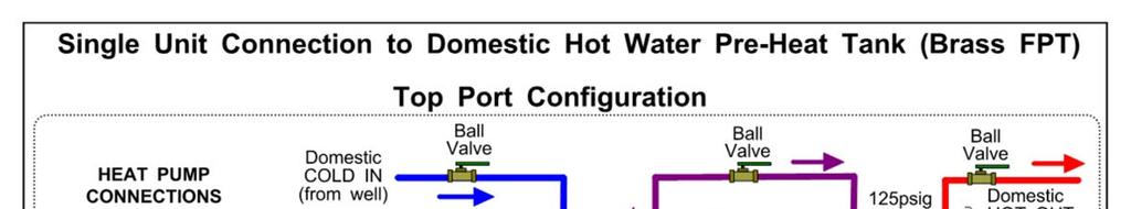
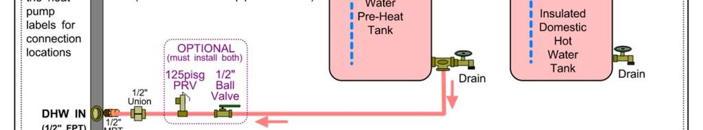
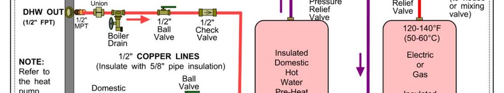
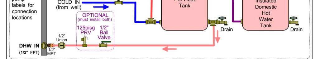
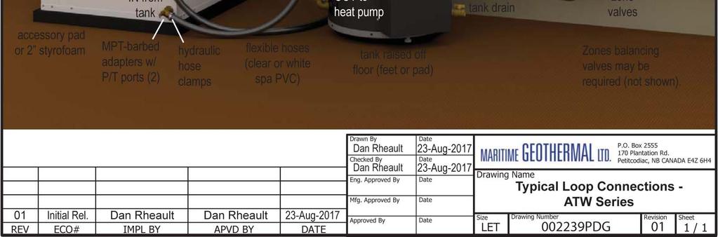
14 Indoor Loop Water Lines The port connections for the Indoor Loop circuit are heavy duty 1 brass FPT fittings. They are labelled as IN- DOOR IN and INDOOR OUT. The ports are located on the front of the unit (refer to DIAGRAM A on page 7). A typical 2 port buffer tank system is shown in drawing PDG. This diagram shows all of the recommended components as well as where they should be placed. A typical 4 port buffer tank system is shown in drawing PDG. Unions or some other form of disconnect should be used so that the coaxial heat exchanger may be accessed should it require cleaning. NOTE: It is recommended that the water lines between the heat pump and the buffer tank be copper or other high temperature piping. NOTE: Care should be taken when routing the water lines to ensure that adequate access to the heat pump is maintained so as to not compromise ease of serviceability. The minimum buffer tank size should follow the rule of 8USGAL per ton of heat pump capacity. TABLE 9 shows the minimum buffer tank size for each heat pump along with the recommended size. The recommended size will minimize the number of starts per hour and provide longer runtimes for improved efficiency. Heat Pump Size TABLE 9 - Buffer Tank Size Minimum Size gallons (Litres) Recommended Size gallons (Litres) (61) 50 (190) (91) 50 (190) (121) 70 (265) (151) 70 (265) (182) 70 (265) If a tank size is not available take the next size larger tank. Domestic Hot Water (Desuperheater) Connections The port connections for the DHW circuit are 1/2 brass FPT fittings. They are labelled as DHW IN and DHW OUT. The ports are located on the front of the unit (refer to DIAGRAM A). A typical piping diagram for a pre-heat tank configuration can be found in drawing PDG at the end of this section. Be sure to note the position of the check valve and the direction of water flow. Other configurations are possible, and there may be multiple units tied together in larger buildings. WARNING: USE ONLY COPPER LINES TO CONNECT THE DESUPERHEATER. TEM- PERATURES COULD REACH 200F SHOULD THE DHW CUTOUT SWITCH FAIL, POTEN- TIALLY MELTING & RUPTURING PLASTIC PIPING. Ensure the tank is filled with water and under pressure before activating the heat pump. Slightly loosen the boiler drain on the DHW Out pipe to allow air to escape from the system before the unit is started. This step will make certain that the domestic hot water circulator in the unit is flooded with water when it is started. Connect the brown wire with the blue insulated terminal to L1 of the compressor contactor. Ensure the power is off when connecting the wire. Once connected the DHW switch on the front of the unit may be used to enable/disable the domestic hot water circulator. The DHW loop may have to be purged of air several times before good circulation is obtained. A temperature difference between the DHW In and DHW Out can be felt by hand when the circulator pump is operating properly. CAUTION: the domestic hot water pump is water lubricated; damage will occur to the pump if it is run dry for even a short period of time. For the pre-heat tank setup, the final tank should be set to 140 F (60 C), unless local code requires a higher setting. The pre-heat tank does not require electric elements. This setup takes full advantage of the desuperheater as it is the sole heat provider to the pre-heat tank. The desuperheater remains active during the compressor runtime until the pre-heat tank has been completely heated by the desuperheater alone. This setup is more energy efficient than a single tank setup, and eliminates the possibility of reverse heating of the refrigerant gas in cooling mode. CAUTION: If two (2) shut-off valves are located on the domestic hot water ines as shown in the diagram, a pressure relief valve must be installed to prevent possible damage to the domestic hot water circulator pump should both valves be closed. Page 14
15 Page 15

16 Page 16

17 Page 17

18 Page 18
19 Sample Bill of Materials - ATW Series Although not exhaustive, following is a list of materials needed for a typical installation: FROM MARITIME GEOTHERMAL ATW SERIES HEAT PUMP W/ACE OUTDOOR UNIT SHIELDED 18-8 WIRE BUFFER TANK W/ELEMENTS kw OPTIONAL FROM MARITIME GEOTHERMAL ANTI-VIBRATION PAD SOUND JACKET SECURE START AHW-65 AIR HANDLER(S) DHW: PREHEAT TANK, 40 OR 60 GAL ½ COPPER PIPE ½ FITTINGS, BALL VALVES, BOILER DRAINS, CV ELECTRICAL HEAT PUMP SERVICE WIRE 6-3 OR 8-3 BUFFER TANK ELEMENT SERVICE WIRE 14-2 OUTDOOR RATED WIRE W/ DISCONNECT SWITCH FOR OUTDOOR UNIT HEAT PUMP BREAKER BUFFER TANK ELEMENT BREAKER ELEMENT CONTACTOR & ELEC. BOX (IF NOT USING TANK W/ DRY CONTACTS) THERMOSTAT WIRE 18-4 THERMOSTAT WIRE 18-2 FORK TERMINALS FOR TSTAT WIRE (6) REFRIGERATION 1/2 & 7/8 (OR 3/8 & 3/4 ) ACR TUBING PIPE ISULATION EXTRA R410A REFRIGERANT FOR LINESETS >25 FT ZONES CIRCULATOR: HEAT PUMP TO TANK 1 PIPE & FITTINGS: HEAT PUMP TO TANK ZONES CIRCULATOR(S) ZONE TRANSFORMER & CIRC CONTACTOR ZONE VALVES (IF NOT INDIVIDUAL PUMPS) IN-FLOOR PIPING OTHER AIR HANDLERS, DUCTING ZONE THERMOSTATS RELAYS OR ZONE CONTROLLER ZONE SUPPLY & RETURN HEADERS: 1 COPPER PIPE & FITTINGS PIPE & FITTINGS TO ZONES EXPANSION TANK 2 STYROFOAM INSUL. (IF PAD NOT PURCHASED) Page 19

20 Outdoor Unit (ACE) Installation Outdoor Unit Description The ACE is the outdoor section to the 2-piece air source heat pump. The same outdoor unit is used with all air source series heat pumps. There are two sizes of outdoor unit, one for unit sizes 25/45/55 and one for unit sizes 65/75/80. See the Model Specific Information section for more information. The ACE contains only the outdoor refrigerant-to-air heat exchanger (air coil), an ECM hub motor axial fan, and the electronic expansion valve (EEV) that is used in heating mode. All other components are in the indoor unit, including the compressor, water coil, and electronics. Since the indoor unit is isolated from temperature extremes and moisture, unit servicing and component longevity are enhanced. The hub motor fan is speed controlled by the GEN2 control board based on refrigerant suction pressure in heating mode, and refrigerant discharge pressure in cooling mode. This results in maximum airflow when needed, while allowing reduced airflow at other times for noise and power savings. Because of humidity in the outdoor air and low coil temperature, periodic defrost cycles are necessary (as with any air source heat pump) in heating mode. When a defrost cycle occurs, the unit with switch from heating to cooling mode in order to melt any frost or ice that has built up on the outdoor air coil. Traditionally, defrost cycles were done based on a timer, or other simple means. With the GEN2 control system, a defrost cycle is only performed when determined by the controller, which compares outdoor air temperature and suction pressure. In addition, defrost is only terminated when ice is completely removed, as determined by a timer algorithm based on outdoor temperature. This results in power savings and prevention of ice damage to the coil. Outdoor Unit Mounting Height The outdoor unit must remain clear of snow and ice at all times. Good performance depends on good airflow, which of course cannot be achieved if the unit is buried in the snow. To this end, several strategies may be employed. First, look up how much snowfall is expected in your area, either from local knowledge or weather data. The snowfall map included here (DIAGRAM C) can be used as a rough guide for Canada. 1. If the local climate has less than ~4 of snow accumulaton, the unit can be mounted directly on a concrete pad. In this case, care must be taken to ensure refrozen condensate does not build up under unit. 2. The unit can be mounted on angle brackets attached to the side of a building. Be sure to adhere to the minimum clearance requirement of 12 (30 cm), and use brackets designed for twice the unit weight. 3. Two different leg kits which add either 15 (38 cm) or 30 (76 cm) of additional height are available as an accessory from Maritime Geothermal Ltd. To attach the legs, first remove the three bolts with flat washers that hold each foot plate in place. Leaving the foot plate in place on the inside of the cabinet panel, slide the leg over the outside of the panel and re-install the three bolts and flat washers. The Outdoor Ice Channeling design utilized in the ACE also works to minimize or eliminate air coil fin and tubing damage caused by ice in traditional air source units. There is no drip tray under the air coils, so defrost condensate drips directly to the ground, and there is no surface on which it can re-freeze and cause damage. Also, the angled coil means that there is a single line for condensate to run off, so condensate cannot hold between horizontal fin bottoms and re-freeze there. Outdoor Unit Location The ACE unit must be placed outdoors, with the fan pointing away from the building. It should be at least 12 inches (30 cm) away from the building or other obstructions on the back and sides for unimpeded return airflow. There should be little or no obstruction in the fan (front) direction for at least 30 feet (9 m), otherwise airflow and therefore overall performance will be reduced. In addition, there should be at least two feet (0.6 m) of clearance on the electrical box and refrigeration piping side of the unit to facilitate servicing and general maintenance. IMPORTANT NOTE: The line set between the indoor and outdoor units must not exceed 75 ft (23 m) in length. DIAGRAM B: Leg Kit Installation In all cases, be sure to mount the unit using the 4 rubber grommets included with the unit, to dampen any vibration. The unit must be fastened to its mounting surface with four min. 5/16 bolts through these grommets to prevent a tipping hazard due to impact or high wind. Outdoor Unit Wiring Two cables need to be run from the indoor to outdoor unit: a signal cable and a power cable. See page 8 for details. Note that the signal cable needs to be a shielded outdoor rated 8-conductor cable, of minimum 18 gauge (18-8). Since shielded thermostat/signal wire may not be a commonly stocked item at many wholesalers, rolls of this wire are available from Maritime Geothermal. If non-shielded wire is used, temperature readings and fan control may be compromised. Page 20


21 DIAGRAM C: Average Maximum Snow Depth - Canada ( ) Source: Natural Resources Canada Page 21
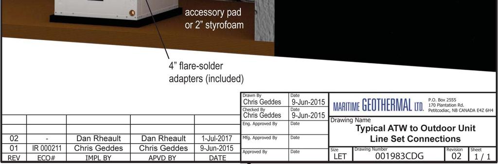
22 Outdoor Line Set Connection & Charging Line Set Interconnect Tubing The indoor unit connections for the interconnect line set are brass service valves with flared fittings. Copper flare to solder adapters are included with the indoor unit, to remove the requirement to do an accurate flare in the field, especially on the larger 7/8 pipe. These are shipped along with the mounting feet for the outdoor unit and shielded 18-8 wire near the compressor in the indoor unit. TABLE 10 - Interconnect Line Set Sizing Remove the side cover (if applicable) from the outdoor unit so that the piping is accessible CDG is an illustration for a typical installation. The tubing used for this procedure must be ACR refrigeration tubing (cleaned & dehydrated). Every effort must be made to insure that the tubing does not become contaminated during installation. We recommend that caps be placed on the open ends of tubing immediately after cuts are made and that these caps are only removed after all bends have been made and the pipe fixed in its permanent location ready to make the silver soldered joints. It is very important to keep a refrigeration system perfectly clean and dry. Removing the caps just prior to silver soldering will ensure minimum exposure to humidity in the atmosphere. Oil Traps IMPORTANT NOTE: The line set between the indoor and outdoor units must not exceed 70 ft (21 m) in length. The outdoor unit has capped off (soldered) pipes from the factory and is charged with psig of nitrogen. The indoor unit comes pre-charged with enough refrigerant for a 20 ft (6.1 m) line set. Once both the indoor and outdoor units have been mounted, the line set may be run between them. The line set consists of a liquid line and a vapour line. The line sizes are based on model size as per TABLE 10. The wrench size for access valve caps as well as the hex key size to open/ close the valves is indicated in the table as well. Liquid Line Vapour Line Model Size Line Size Hex Key Cap Wrench Line Size Hex Key 25/45 3/8 5mm 19mm 5mm 3/4 (3/16 ) (3/4 ) (3/16 ) 55/65/ 5mm 19mm 8mm 1/2 7/8 75 (3/16 ) (3/4 ) (5/16 ) Valve service port caps wrench size is 14mm (9/16 ). Cap Wrench 30mm (1-1/4 ) 42mm (1-3/4 ) If the lineset has a vertical rise of over 20 ft (6 m), then an oil trap must be placed in the line set every 20 ft (6 m) of rise as shown in CDG. Pipe Insulation All line set piping between the indoor and outdoor units should be insulated with 3/8 thick closed cell pipe insulation to prevent condensation and dripping onto floors or walls during the heating season. It can be slid onto the capped tubing without having to slice it down the side for the most part. Ensure that any joints in in the line sets are accessible for leak testing. Liquid and vapour ports and any remaining exposed tubing should be insulated with 3/8 thick closed cell pipe insulation once the silver soldering and pressure testing is complete. Ensure that all individual pieces of pipe insulation are glued to each other so there are no air gaps. Silver Soldering Line Sets All joints are to be silver soldered with 5% silver solder. It is absolutely required that dry nitrogen be bled through the system during all silver soldering procedures so that no oxidation occurs on the inside of the copper tubing. Connect a set of refrigeration gauges to the service ports (Schrader ports) on the access valves of the indoor unit, the low side (blue hose) to the vapour line and the high side (red hose) to the liquid line. Connect the charge line (yellow hose) to a nitrogen source. Disconnect the high side (red) hose at the manifold so that nitrogen may flow freely though the line set. Adjust the nitrogen pressure through the low side (blue hose) so that it can be very lightly felt when a finger is placed on the disconnected high side (red) hose. A wet rag may be wrapped around each of the outdoor unit ports to prevent melting the grommet when silver soldering; however this should not be necessary due to the distance from the grommet. Ensure that no water enters any of the ports or tubing. Pressure Testing Once all connections are complete, the system should be pressure tested to a final test pressure of 125 psig (860 kpa) with dry nitrogen. Reconnect the high side (red) hose to the manifold and pressurize the line set. It is recommended to pressure test in stages, listening and inspecting for leaks along the way. For example, 10 psig (70 kpa), 25 psig (170kPa), 75 psig (520kPa) and then finally 125PSIG (860kPa). Check all joints at the unit and any made in the interconnect tubing for leaks using soap suds, Spray Nine, etc. It is important not to bypass this step as vacuuming the system with a leak will be impossible and attempting to do so will introduce moisture into the system, making the vacuum process take much longer than if the leak had been found and repaired first. It is recommended that the system be left under pressure for a minimum of two hours to ensure there are no small leaks that were undetected. Vacuuming the System Remove the pressure from the system and connect the vacuum pump to the charge line (yellow hose) of the refrigeration manifold. Tighten all hose connections, open the valves on the manifold and start the vacuum pump. Vacuum the system until the reading on an electronic vacuum gauge remains below 500 microns for a period of 5 minutes after the vacuum pump is shut off and the system sealed. Page 22
23 Charging the System The indoor unit is pre-charged as per TABLE 11. Once the system has been vacuumed, if extra refrigerant is required due to the length of the line set, it may be added before opening the access valves. Close off the charge valve on the refrigeration manifold set and disconnect the vacuum pump. Connect the charge (yellow) hose to the liquid port of a refrigerant tank and place the tank on a scale. Open the liquid valve of the refrigerant tank and then slightly loosen the charge (yellow) hose at the manifold until liquid comes out, then quickly re-tighten the hose. This will ensure that no air enters the system. Zero the scale and then add the calculated amount of refrigerant from TABLE 12 or TABLE 13. Once the additional charge (if any) has been added, disconnect both hoses from the service ports of the access valves and place the caps back on them, tighten with a wrench. Remove the caps from the access valves and open both valves with a hex key. Open the valves (counter-clockwise) until they stop turning. Replace the caps and tighten with a wrench. The system is now ready for startup. Clean up the area, install all access panels except the one which gives access to the electrical box. Proceed to the Startup Section of the manual before turning the power on to the unit. Model Size lb kg 25 TBD TBD TABLE 11 - System Charge Chart Extra length of line set (Models 25 and 45) Extra length of line set (Models 55, 65 and 75) 1.1oz per foot 2.1oz per foot 0.10 kg per metre 0.18 kg per metre TABLE 12 - Extra Charge Chart (Sizes 25-45) Extra Extra Charge Charge (oz) (lb) Total Lineset (ft) Extra Charge (kg) TABLE 13 - Extra Charge Chart (Sizes 55-75) Extra Extra Charge Charge (oz) (lb) Total Lineset (ft) Extra Charge (kg) Page 23

24 Page 24
25 Sizing & Hydronic Installation Heat Pump Sizing TABLE 14 contains a guideline to the size of home each air source heat pump size can handle. TABLE 14 - Heat Pump Size vs. Heated Area Model sq.ft. m , , , , This is which unit size is required for a typical two-level home (main level and below grade basement) with R-20 walls, R-40 ceiling and average size and number of windows. The Heated Area is the area of the main level. The table accounts for a basement the same size as the heated area. IT IS HIGHLY RECOMMENDED THAT A PROPER HEAT LOSS/GAIN ANALYSIS BE PERFORMED BY A PROFES- SIONAL WITH APPROVED CSA F-280 SOFTWARE BEFORE SELECTING THE SIZE OF UNIT REQUIRED FOR THE APPLI- CATION. The analysis will result in a heat load for the coldest day, which is influenced by, for example, the number of levels, the size of the windows, the orientation of the home, attached garage, bonus rooms, walk-in basement, and coldest outdoor temperature for the region. A heat pump model size can be selected by matching the calculated heat load to a heat pump s standard capacity rating at an outdoor temperature of 35 F (1.7 C), which is the AHRI H2 2 test condition. These are listed in the Model Specific Information section later in this manual. This sizing will result in a good compromise between covering as much of the cold weather heat load as possible without utilizing backup heat, while minimizing excessive cycling (turning on and off frequently) during moderate outdoor temperatures. It should be noted that sizing an air source heat pump is always a compromise between covering coldest-day heat load and minimizing cycling due to over-capacity in warm weather. In cooling dominant climates, the heat pump should be similarly sized, by matching the calculated cooling load to the standard capacity rating at an outdoor temperature that matches the local maximum outdoor temperature. The difference here is that it is necessary to cover all of the cooling load, since there is no backup cooling. Hydronic Systems Hydronic systems typically provide heat through two different types of media: radiant in-floor heating forced air heating via fan coil units One of the benefits of hydronic systems is the flexibility in setting up the heating system. Whereas a typical forced air system has one central thermostat controlling the entire heating system, the home may be sectioned into several areas called zones with a hydronic system. Each zone has its own thermostat, allowing simple separate temperature control of the individual areas in the home. There are other uses for hydronic systems, the two most common being on-demand domestic hot water and pool/spa heating. Drawing PDG shows the most common types of zones. A typical system consists of the heat pump, the buffer tank and the zones. The heat pump s sole purpose is to maintain the buffer tank set point. Its operation is independent of the zone operation. Drawings PDG and PDG earlier in this manual show typical piping configuration for a single unit with two port or four port buffer tank. This is a guideline for a simple installation. There are many other configurations, such as separate heating and cooling buffer tanks, multiple units connected to one buffer tank, etc. It is recommended that the hydronic system be designed by a qualified system designer to ensure proper functionality. Fan coils can be used to provide heating and/or cooling for areas that do not have radiant in-floor heating. They provide a means of air heating/cooling with minimal or no ductwork. Note that the buffer tank temperature should be set for 115 F (46 C) if there are fan coils in the system. Two port fan coils are recommended for connection to the system if a single buffer tank is used for heating and cooling. For systems with separate hot and cold buffer tanks, two port fan coils are recommended for zones that provide only one function (heating or cooling), while four port fan coils are recommended for zones that heat and cool. These are simply suggestions, the fan coil selection will depend on the final system design. It is recommended that all piping be insulated with 3/8 thick closed cell pipe insulation. This is a MUST for any piping that is used for cooling to prevent dripping onto floors and walls. Care should be taking when wiring the system to ensure that radiant in-floor heating zones are disabled whenever the heat pump is switched to cooling mode. Even in northern heating dominant climates, it should be ensured that 100% of the cooling load will be covered when sizing the heat pump. Page 25
26 Page 26
27 System Operation General Overview The ATW-Series heat pumps are reversing air to water heat pumps. The refrigeration circuit diagrams for the units can be found in the Model Specific Information section of the manual. The system consists of an indoor unit and an outdoor unit. The outdoor unit contains only an air coil and ECM fan, the heating mode EEV, along with the outdoor temperature sensor. The remaining components are found in the indoor unit, including the compressor (which is unlike most air-source systems). This has several advantages, for example minimal work must be done outside, important components are in the conditioned space for longevity, and domestic hot water (desuperheater circuit) is possible as the lines are inside and will not freeze. The system is controlled as selected by the Control Source parameter (BACnet, Setpoints or Signals). Heating Operation In heating mode the unit provides hot water to the buffer tank. Superheat is controlled by the heating EEV located in the outdoor unit while the EEV in the indoor unit is set to full open. As the unit operates, heat is extracted from the outdoor air, which causes the air coil to eventually frost up to the point that a defrost cycle is required. The time between defrost cycles varies depending on the outdoor conditions; refer to the Defrost Operation section below. If the outdoor temperature is above 34 F(1 C), the outdoor unit fan starts and stops when the heat pump starts and stops. If the temperature is below 34 F(1 C), the fan will remain on at a very slow speed when the heat pump is off in order minimize the chance of a fan freeze up as well as help prevent snow from entering the unit through the fan opening during a snow storm. The outdoor fan is controlled based on the suction pressure and will slowly ramp up to the required speed when the system starts. The heat pump will turn off and only the auxiliary heating system will operate if the outdoor temperature gets too cold. Refer to the Model Specific Information section for the limits of operation. Cooling Operation In cooling mode the unit provides chilled water to the buffer tank. Superheat is controlled by the cooling EEV located in the indoor unit while the EEV in the outdoor unit is set to full open. As the unit operates, heat is extracted from the buffer tank and rejected to the outdoor air. The outdoor fan is controlled based on the discharge pressure and will slowly ramp up to the required speed when the system starts. During operation the fan speed will automatically adjust up or down to in order to maintain the discharge pressure setpoint value. The discharge pressure will begin to rise above the setpoint when the outdoor temperature exceeds the point at which the outdoor fan speed reaches its maximum value. Two stage units will drop down to the first stage to reduce the discharge pressure at elevated outdoor temperatures. Refer to the Model Specific Information section for the limits of operation. There is no defrost cycle when in cooling mode. Defrost Operation The ATW series heat pump has an advanced defrost control algorithm intended to provide a minimal number of defrosts and minimal defrost cycle time while achieving complete defrost The outdoor unit s unique design also has excellent resistance to coil freeze-ups and potential future coil damage as a result of repeated freeze ups. The system uses the outdoor temperature and suction pressure to determine when a defrost cycle should occur as well as how long it should be. PID fan control allows the discharge pressure to rise quickly and then be maintained at a desired setpoint for quick defrosting. A defrost disabled period occurs after a defrost cycle which allows a potential problem with the unit to be identified as an alarm and prevents repetitive defrost cycles if this is in fact the case. The outdoor unit has a unique design for combatting ice build up, a common problem with air source units. The coil sits on a 15 angle and the area below the coil is completely open. The angle causes the melting frost/snow to run down the back of the coil which creates a single line of run off along the back bottom edge of the coil rather than a runoff from the entire bottom of the coil. This concentrates the weight of the runoff over a much smaller area and thus run off occurs more quickly and at a higher velocity, minimizing the amount of runoff that remains trapped at the bottom of the coil due to surface tension between the coil fins. Any leftover runoff will freeze during the next heating cycle so it is extremely important to minimize this. Since the coil is on an angle, the comparatively small amount of runoff left versus a traditional flat coil is actually only around the back corner of the coil, making it virtually impossible for runoff to remain between coil two pipes and freezing between them, a common cause of eventual coil failure. Page 27


28 PC Application (PC App) NOTE: Before using the PC Application refer to Appendices B and C for installation instructions for the PC Application and USB driver for the com port. Both must be installed in order to run the PC APP and communicate with the control board. Connect a USB cable between the PC and the control board USB connector located at the bottom center of the board. Double click on the NordicGEN2Vx.xx application to launch the PC APP. You should see a screen similar to the one below. The revision of the PC APP is shown in the top left corner of the screen. Click the Connect button to begin communications with the control board. Once connected, the menus and buttons will become accessible, the number of Objects available and Read should appear (they should be the same) and the Polling LED will begin to flash. The PC time and date will appear at the bottom left corner of the screen. Clicking on Control Board Date and Time will display the current control board date and time. If the date and time need to be adjusted, click on menu Tools Set Date and Time. The control board date and time will be set to that of the PC. PC Application Menus The following pages describe the PC APP s menus in detail. There are five main menus: File, View, Graphs, Tools, Help. File Menu: This menu handles page arrangements. If one or multiple pages are open and arranged as desired for viewing, this page arrangement may be saved and re-used the next time the PC APP is used. File Open: File Save: File Save As: File Exit: Opens a saved page arrangement. Saves the current page arrangement under the current name. Save the current page arrangement under a new name. Exits the PC Application. Windows Menu: This menu is used to arrange windows (pages), or to bring a particular window to the front. Windows Cascade: Windows Tile Vertical: Windows Tile Horizontal: Windows Close All: Windows Window Name: Arranges windows one in front of the other each with a small right and down offset from the last. Arranges windows side by side, stretching them fully from top to bottom. Arranges windows up and down, stretching them fully from left to right Closes all open windows. Brings the named open window to the front. Help Menu: This simply shows information about the PC Application. Help About: Displays the window shown to the right. Page 28


 Outdoor fan speed, setpoint pressure and current pressure. Force a defrost cycle to occur immediately.")
29 View Menu: This menu handles all of the operational viewing screens. Clicking on the View submenus will open the page in the PC APP s frame. The next few pages of the manual show screenshots of each of the pages along with some descriptions of what is on each page. View Control Panel: The main control screen page will open, shown below. View Defrost History: The defrost history window will open, shown below. Same as clicking on History on main screen. View Stage Stats: The compressor information: number of starts, run hours and starts per hour, shown below. Heat pump model information. Operational status of the heat pump system. Manual controls are enabled when in MANUAL OVER- RIDE mode. Clicking the SERVICE button will disable the unit and fully open both EEV s to allow repair work to be done to the refrigeration system. Stage run timers. Indicators show the demand from the control system. Compressor information, refer to Stage Statistics window shown below. Auxiliary information. Status light indicates when in use. Refrigeration system pressure data, along with alarm indicators. Refrigeration system temperature data. Indoor EEV. Status light indicates when in use. Reversing valves. Status light indicates when in use. Outdoor temperature (sensor located in Outdoor Unit) Outdoor fan speed, setpoint pressure and current pressure. Force a defrost cycle to occur immediately. Selectable temperature at which compressor is disabled. Force Stage2 on after Stage1 has been operating for x minutes. Set to 0 to disable this functionality. Short Cycle timer and override button for when unit is being serviced. Outdoor EEV. Status light indicates when in use. Defrost data: start pressure at which defrost will be triggered, timer for defrost cycle and defrost disabled cycle. Override button for when unit is being serviced. History button opens Defrost History window. Click on STATS button or menu View-Stage Stats to open the window below. Real-time display of defrost state. Export the history as tab delimited. Clear the defrost history log. Number of defrosts since history was last erased. Refresh button reloads the defrost log. Defrost history log. Erase the compressor statistics (only for if a compressor should need to be replaced). Page 29
30 View Alarms: The alarms page has three tabs, the first shows the current alarm status, number of alarms, high and low refrigeration alarm cutout values as well as the short cycle timer. The second tab shows a list of alarms that have occurred since the PC APP has been operating (this will be lost when the PC is disconnected from the controller board.) The third tab is a list of board hardware faults. RESET button: This will reset all alarms and alarm counts, including a permanent alarm. WARNING: Repeated resets can freeze and rupture the heat exchanger, ruining the heat pump and voiding the warranty.the source of the alarm should be determined before resetting the unit if possible or during operation after a reset. ALARMS Tab (see screen shot on next page): NOTE: Greyed out Alarms in the PC APP are not applicable to the system setup and are not monitored by the control board. NOTE: Refer to Alarms and Faults screenshot below to see which alarms have a count. Alarms without a count: These alarms only occur one time at which point they immediately create a Permanent Alarm. Alarms with a count: Master Alarm: Permanent Alarm: Low Pressure: High Pressure: Compressor Monitor: Compressor Status: Phase Monitor: Loss of Charge: Multiple Defrosts: Outdoor Flow: Indoor Flow: When an alarm occurs the compressor will stop, the alarm count will increase and the Short Cycle Timer will start. When the SC Timer expires the compressor will re-start. If no further alarms occur within Count Reduce Time, the alarm count will be reduced by 1. If another alarm occurs within Count Reduce Time (see Configuration Page) the count will increase by 1. If alarms continue to occur, when the alarm count reaches the Maximum Count value a Permanent Alarm will occur. This alarm occurs when any permanent alarm occurs. It is used to simply indicate that there is an alarm. The compressor will be locked out until the Permanent Alarm is manually reset either by cycling the power or clicking on the RESET button A low pressure alarm occurs when the suction pressure drops to or below the Low Pressure Cutout value. The low pressure is checked just before a compressor start, if it is OK the compressor will start, otherwise an alarm will occur. When the compressor starts, the low pressure alarm will be ignored for the number of seconds that Low Pressure Ignore is set to, after which the low pressure alarm will be re-enabled. This allows a dip in suction pressure below the cutout point during startup without causing a nuisance alarm. A high pressure alarm occurs when the discharge pressure rises to or above the High Pressure Cutout Value. This alarm occurs when the compressor protection module sends a fault signal to the control board, generally due to the compressor windings overheating. This alarm occurs when there is a current draw on the compressor but no call for the compressor to be on (ie welded contactor) or when there is a call for the compressor to be on but there is no compressor current draw (ie manual high pressure control is open or contactor failure). Requires current sensor accessory. This alarm occurs when the Phase Monitor detects a fault condition and sends a fault signal to the control board. For three phase units only and requires Phase Monitor accessory. This alarm occurs if both the low pressure and high pressure sensors are below 30PSIG (207kPa). This alarm occurs if a second defrost occurs immediately after the defrost disabled timer elapses from a previous defrost cycle. This alarm is ignored on compressor start for the number of seconds the Outdoor Flow Ignore on Start is set to. Alarm monitoring will begin when the timer expires. This alarm is ignored on compressor start for the number of seconds the Indoor Flow Ignore on Start is set to. Alarm monitoring will begin when the timer expires. IMPORTANT NOTE: The datalogging function of the GEN2 Control Board is a very useful tool for troubleshooting alarms. It provides a history of the unit operation up to and including the time at which the alarm(s) occurred. Go the Alarms Troubleshooting section of the Trouble Shooting section of the manual to address alarm issues. Page 30


31 Master Alarm occurs when any alarm occurs. This button will erase all alarms and alarm counters, including a permanent alarm. Low Pressure Cutout. High Pressure Cutout. Greyed out alarms are not applicable to the system. Short Cycle Timer counts down time until the next compressor start is allowed. This button will reduce the short cycle timer value to 10 seconds. ALARMS LIST Tab: This tab show a history of alarms that have occurred since the PC APP was connected to the control board. This list will be lost when the PC APP is disconnected. Each alarm that occurs while the PC APP is connected to the control board will appear here. The alarm type and a time stamp will be shown. The alarms list will be erased when the PC APP is disconnected from the control board. This button will erase the alarm events in the Alarm List. Page 31

32 BOARD FAULTS Tab: This tab shows hardware faults that could occur. If one of these faults occurs there may be a problem with the control board hardware or with the LCD Display and buttons. NOTE: If a Board Fault occurs, try cycling the power to the heat pump. Turn the power off for 10 seconds and then back on again. If the fault persists then there is most likely a problem with the hardware and the board will need to be replaced. Digital Inputs: A failure has occurred and the Control Board may no longer respond to the digital input signals. Digital Outputs: A failure has occurred and the digital outputs may no longer work properly. PWM Outputs: A failure has occurred and the PWM / 0-10VDC outputs may no longer work properly. Analog to Digital: A failure has occurred and the data from the A/D converter may be corrupt resulting in erratic data values. Real Time Clock: A failure has occurred, system time / date may no longer be valid, all time stamped data may be corrupt. Flash Memory: A failure has occurred stored data may be corrupt. It may be possible to correct this by using the menu item Tools Reset to Factory Defaults. If this clears the fault then the system configuration will have to be setup again. Menu Buttons: A failure has occurred and the Control board may no longer respond to menu button keypresses. Try turning off the power, disconnecting and reconnecting the cable between the LDC Display board and the Control Board and then turning the power back on again. If this does not work then either the LDC Display board, the cable or the driver section of the Control Board may be faulty. LCD Display: A failure has occurred and display may show erratic data, no data or may not turn on at all. Try turning off the power, disconnecting and reconnecting the cable between the LDC Display board and the Control Board and then turning the power back on again. If this does not work then either the LDC Display board, the cable or the driver section of the Control Board may be faulty. Temperature Sensors: A failure has occurred or the sensor is disconnected. Greyed out sensors do not to apply to the system as configured. Some sensors may be optional, go to the Configuration Page to enable/disable them. IMPORTANT NOTES: The heat pump will not operate if the Outdoor Ambient probe (HTS) is faulty or disconnected. The auxiliary will continue to operate but it s sepoint value may be reduced if using the Outdoor Reset function. If the Indoor OUT (I_OUT) probe is faulty or disconnected, neither the heat pump nor the auxiliary will operate if using Setpoint Control. They will continue to operate under Signals or BACnet control. Greyed out do not apply. Fault Indicators Page 32


33 View Setpoint Control : Shows the on-board aquastat control screen. This screen is only available when Control Source HYD on the Configuration Page is set to Setpoints. This screen is described in detail in the Setpoint Control section of the manual. The screens below show a two-stage model on the left and a single stage model on the right. Refer to the SETPOINT CONTROL section of the manual for a complete description of operation. View Water Lines: Shows the water line temperatures. For the ATW series, the Indoor IN and Indoor OUT are connected to the water lines inside the unit. The Outdoor lines are unused. Page 33


, and the multiplier and Offset values may be set to accommodate the connected")

34 View Digital Inputs: Shows the digital inputs and their individual status (ON/OFF). They may be individually controlled when in Manual Override Mode in order to facilitate trouble shooting. View Digital Outputs: Shows the digital outputs and their individual status (ON/OFF). They may be individually controlled when in Manual Override Mode in order to facilitate trouble shooting. View Analog Inputs: Shows the Analog inputs and their individual settings and values. Click on the EDIT button to modify the blue boxes (button will now say SAVE). For each channel a name may be selected (up to 16 characters), and the multiplier and Offset values may be set to accommodate the connected sensor scaling. Signals may be 4-20mA (channel jumper on board ON) or 0-10VDC (channel jumper on board OFF). A variety of units are also available for selection of common measurement types. Click on SAVE to save the changes. Values are kept even when power is removed from the unit. View PWM Channels: Shows the PWM channels and their individual status (0-100%). They may be individually controlled when in Manual Override Mode in order to facilitate trouble shooting. Page 34
35 Graphs Menu: This menu is a list of the available graphs. Graphs are real-time and show a time stamp of when the recording started as well as a current time which will show when the graph was Screen Printed. Each graph has a CLEAR button which will erase the stored data and restart the graph. There is also a master CLEAR ALL button at the top right of the PC APP, this will clear all open graphs and re-start them all simultaneously to keep them in sync with each other. The refresh rate for the graphs is also located at the top right of the PC APP. TIP: To screen print a graph and save it as a picture, press Print Screen and then paste the clipboard into MS Paint. Select the desired graph with the selection tool and copy it to a new MS Paint, then save the file as the desired name. Here is the complete list of available graphs: Graph Control Signals Graph: EEV Graph: Refrigeration Pressures Graph: Refrigeration Temperatures Graph: Outdoor Fan Graph: Outdoor Temperature Graph: Water Lines Graph: Discharge vs Hot Tank Graph: HTS CTS Graph: Analog Inputs Graph: PWM Channels Graph: Input Power Graph *: An example of a graph is shown on the next page. ON/OFF status of the system control signals. EEV position, the suction line temperature and superheat. Suction and discharge pressures. Evaporation and condensing temperatures. Suction (heating) or Discharge (Cooling and defrost) pressure vs outdoor fan speed. Suction (heating) or Discharge (Cooling and defrost) pressure vs outdoor temperature. Indoor IN, Indoor OUT and Indoor Delta T values. Discharge pressure vs tank temperature. For control systems using the HTS and/or CTS probe(s). All six analog input channels (0-10VDC or 4-20mA). All four PWM / 0-10VDC output channels as well as one PWM / 0-10VDC input channel. For future use. Page 35

36 Below is an example of a typical graph screen. Items that are checked will be plotted, unchecked items will not. The graph screens show the time the graph started as well as the current time to time stamp the graph when screen printed. Graph Name. Refresh Rate. Graph Start Time. Graph Printed Time. CLEAR button erases all graph data. Checkboxes to select which items are graphed. Current values. Primary Y axis on the left, Secondary Y axis on the right. X axis = Number of samples. Elapsed time = Number of Samples x Refresh rate. ie 20 samples by 1second refresh = elapsed time of 20seconds. Page 36

37 Tools Menu: This is a list of the various tools are used for system setup and monitoring. Tools Configuration: This is where the system setup is done. THIS SHOULD BE DONE ONLY BY A QUALIFIED INSTALL- ER. Improper settings could cause the system to operate poorly or not at all.! WARNING: Selecting the wrong Fluid Type and/or Fluid mixture can cause the heat exchanger to freeze, possibly rupturing it and destroying the heat pump, VOIDING THE WARRANTY. Ensure the Fluid Type and Fluid mixture match the fluids and mixtures that have actually been put into the system. Model Configuration is used to select the system type. Firmware Revision can also be seen on the LCD Display during power up. Green when parameters have been updated, red during the update. Clicking this will reset the saved parameters to the default values. The configuration will need to be completed afterwards. Enable/Disable the compressor. Units are shipped as Disabled to prevent an unintentional compressor startup. Fluid selection determines the low pressure cutout value. Select the appropriate Fluid Type and Fluid Mixture by volume. SEE WARNING ABOVE. Low pressure cutouts are determined by the combination of Refrigerant Type, Fluid Type and Fluid Mixture. High pressure cutouts are determined by Refrigerant type. Control Source HYD selects how the system will be controlled. The options are: BACnet, Setpoints and Signals. The Enabled Indicators show which alarms are enabled and which are disabled. Jumper configuration is used to select system options. Items that do not pertain to the type of system selected are greyed out. Selects whether or not the AUX Heat is activated when in defrost mode. Default value is disabled. This is for Setpoint Control operation only. Selects whether there is one or two tanks (hot and cold) in the system. Default value is One. This is for Setpoint Control operation with HTS/CTS method only. Selects whether or not to use the internal temp sensor (default) or external sensor(s) This is for Setpoint Control operation only. If an alarm is standard or not available the Enable button will be greyed out. If an alarm is optional (may require accessory items) the Enable button will be accessible, click on it to enable the alarm. Page 37
38 The following describes each item on the Configuration Tab of the Configuration Page. IMPORTANT NOTE: System setup is done at the factory. Normally, only the control source, optional alarms and fluid type / fluid mix may need to be changed. Note that items that become unavailable or are automatically selected will be greyed out. Model Configuration: These are used to select the type of heat pump the control board is installed in. Model Series: Select the model series (refer to nameplate on unit) This will update remaining items to default values. Model Size: Model Function: Refrigerant Type: Number of Stages: EEV Step Range: Select the model size (refer to nameplate on unit). Select the model function (refer to the nameplate on the unit). Select the refrigerant type (refer to the nameplate on the unit). Select the number of stages (refer to the compressor model: ZP = 1 stage, ZPS = 2 stage). Automatically selected. Jumper Configuration: These are system level settings. Control Source AIR: Not Applicable. Control Source HYD: Setpoints Method: Air/Hydronic Priority: Number of Tanks: Fan En. For Hydronic: Heat Pump / Chiller: HYD AUX in Defrost: Fluid Selection: Fluid Type (Outdoor): Fluid Mix (Outdoor): Fluid Type (Indoor): Fluid Mix (Indoor): Pressure Cutouts: Alarm Controls: Outdoor Flow: Indoor Flow: Outdoor IN and OUT: Indoor IN and OUT: Phase Monitor1: Compressor Status1: Compressor Monitor1: Select desired control source: BACnet: System is controlled via BACnet MS/TP RS-485 Interface. Refer to the BACnet Interface Section of the manual for more information. Signals: System is controlled via hardwired signals from an external source. Refer to the Thermostat Requirements section of the manual for more information. Setpoints: System is controlled via on-board aquastat functionality. Refer to the Setpoint Control section of the manual for more information. Applicable only if Setpoints selected for Control Source HYD. Select Indoor Loop (default) for the Indoor Circulator Sampling method or HTS / CTS to use external probes mounted in tanks. Not Applicable. Applicable only if Setpoints selected for Control Source HYD and HTS / CTS selected for Setpoints Method and a reversing model (HAC or HACW). Select One for single tank systems or Two for sys tems with a hot and cold tank. Not Applicable. Not Applicable. Selects whether or not the hydronic auxiliary heat is activated during defrost mode (default is disabled). Used to select the Indoor and Outdoor fluid types and volume mixture ratios. Automatically Selected. Automatically Selected. Select appropriate fluid type to match the antifreeze type (or water) in the loop. Select fluid mixture ratio (by volume). Greyed out if Fluid Type is water. Automatically Selected based on Refrigerant Type, Fluid Type and Fluid Mixture. These are optional or automatically selected alarms. If a button is greyed out and the Enabled Indicator is on the alarm is automatic, if the Enabled Indicator is off then the alarm is not available. Buttons that are not greyed out are optional alarms. Not Applicable. Not Applicable. Automatically selected. Automatically selected. Optional, for three-phase models only, requires Phase Monitor accessory. Optional, requires current sensor accessory. Not Applicable. Page 38
, click on OK.")
39 The screenshot below shows the Alarms and Delays tab of the Configuration Page. Click on the UP/DOWN arrows to change the value, note that values have both a low and high limit. Once values have been selected, click on APPLY to save the changes, a confirmation window will appear (see below), click on OK. Short Cycle Delay is the number of minutes before the unit can start again after a normal shutdown. The number of minutes before the unit can start again after alarm shutdown. Click on UP/DOWN arrows to adjust values within the range limits. Ignore On Start is the number seconds an alarm will not be monitored after a compressor start occurs. Maximum Count is the number of alarms allowed before a permanent lockout occurs. Count Reduce Time is the number of hours after which the alarm count is reduced by 1 if no other alarm occurred within the timeframe. Items that do not apply to the model are greyed out. Page 39


40 Tools Calibration: NOTE: Generally there is no need for calibration. The suction and discharge pressures may be calibrated in increments/decrements of 1PSIG if there is a discrepancy in the readings when compared to a known good reference. Temperature sensors may be adjusted in increments/decrements of 0.1F. There is an AUTO CALIBRATION routine in the program that continually calibrates the temperatures sensors against an on board reference by applying an offset to the temperature sensors. Calibration adjustments made here are in addition to the Aut- Calibration routine. Click on the RESET ALL CALIBRATIONS button to clear all calibration data. A popup window will appear for confirmation. Calibration Adjustment. Pressures are +/-1PSIG, temperatures are +/- 0.1 F. Current values in standard and metric. Temperature Auto Calibration information. The offset is applied to the temperature sensors. Calibration adjustments made here are in addition to the Auto Calibrated Values. Tools Set Date and Time: This will synchronize the date and time of the Control Board with the PC date and time. The Date and time of both the PC and the Control Board are shown in the status bar at the bottom of the APP. Click on the Control Board Date and Time(Click): button to show/refresh the control board date and time. Tools Reset to Factory Defaults: This will reset all parameters to default values. THE SYSTEM MUST BE RECONFIGURED AFTER A RESET IS PERFORMED. A reset will default the system to a two stage ATW Series Size 65 with Signals as the control source. Calibrations, alarm delays, analog configurations, compressor statistics and Setpoint Control values will be returned to defaults as well. Page 40


41 Tools Datalogging: This will display the on-board datalogging screen. The datalog rate is set via the dropdown box at the top right of the APP. A log will be taken at the datalog rate whenever the system is operating or the system is off and the SC Timer is counting down. It will stop taking logs after the SC Timer expires until the system restarts again. It will stop taking logs when a permanent alarm occurs. The functionality of the screen is described below. Click on the Enable/Disable tab to customize which columns are shown/hidden. Click on this tab to customize which columns are shown/ hidden. Loads the # of LOGS beginning from the earliest date. Loads the # of LOGS beginning from the selected date. Erases the screen only. Export the data to a file. Erases all logged data in the control board and resets the log count to 0. Clicking anywhere on a row will update all LEDs to show the status at the time of the log. Click on the checkboxes to customize which columns are shown/hidden in the datalog table. Tools Set Date and Time: This will synchronize the date and time of the Control Board with the PC date and time. The Date and time of both the PC and the Control Board are shown in the status bar at the bottom of the APP. Click on the Control Board Date and Time(Click): button to show/refresh the control board date and time. Tools Reset to Factory Defaults: This will reset all parameters to default values. THE SYSTEM MUST BE RECONFIGURED AFTER A RESET IS PERFORMED. A reset will default the system to a two stage ATA Series Size 65 with Signals as the control source. Calibrations, alarm delays, analog configurations, compressor statistics and Setpoint Control values will be returned to defaults as well. Page 41


42 Tools MODBUS: For Future Use. Tools Parameters: WARNING! The Parameters page is for advanced use only. Changing parameter values can cause the system to stop functioning properly. The parameters page shows all configurable memory spaces with their name and current value and allows them to be edited directly. To change a parameter value type in the new value and press ENTER. Clicking on menu item Tools Parameters will display this warning. Type in the new value and press ENTER, the confirmation popup will appear, click on OK. Click on YES to open the parameters page. Click this button to reload the table with the values from the control board memory. Page 42

43 Tools SYSTEM TIMERS: This page shows all timers by name along with their current values. Page 43


44 LCD Display & Menus Below are three pictures of the LCD Display and menu buttons. They are examples of the unit status and operating data displayed when at the message display level (top level). Pressing ENTER will enter into the menu levels beginning with the Main Menu. Pressing OK will toggle between message auto scroll and manual scroll modes. UP and DOWN do not do anything if in auto scroll mode; they cycle through the messages if in manual scroll mode. 2x16 LCD Display ENTER button: Use this to push down to the next menu level. Also saves value if at parameter menu level. UP button: Use this to scroll up through the items available at a menu level. DOWN button: Use this to scroll down through the items available at a menu level. OK/EXIT button: Use this to come back up one menu level. Also saves value if at parameter menu level. Page 44
45 Main Menu: This is a list of the various tools are used for system setup and monitoring. They are each described below. The table shows what is displayed based on each press of the ENTER button starting at the Main Menu level. ENTER (From Main) ENTER (First Press) ENTER (Second Press) ENTER (Third Press) Setpoint Control Setpoints Heating Stage 1 Setpoint (only if using Setpoint control) Stage 1 Delta Stage 2 Setpoint Stage 2 Delta AUX (S3) Setpoint Description Stage 1 stops when water temperature rises to this point. Stage 1 starts when water temperature drops below setpoint by this amount. Stage 2 stops when water temperature rises to this point. Stage 2 starts when water temperature drops below setpoint by this amount. Stage 3 stops when water temperature rises to this point. Stage 3 time delay starts when water temperature drops below setpoint by this AUX (S3) Delta amount. (Stage 3 starts immediately if time delay is set to 0). AUX (S3) Delay Delays Stage 3 start by timer amount. Outdoor Reset Cooling Stage 1 Setpoint Stage 1 Delta Stage 2 Setpoint Stage 2 Delta Temperature factor to use in the outdoor reset table. Stage 1 stops when water temperature drops to this point. Stage 1 starts when water temperature rises above setpoint by this amount. Stage 2 stops when water temperature drops to this point. Stage 2 starts when water temperature rises above setpoint by this amount. System Enable System Disabled Disable compressor, auxiliary and ICR. Enabled Enable compressor, auxiliary and ICR. Service Mode Service Mode? No Do not enter Service Mode. Yes Enter into Service Mode. EEV Control EEV1 (Local) Auto/Manual Auto Puts EEV in Auto mode Manual Puts EEV in Manual mode Manual Position EEV Position (%) Sets EEV to manual position EEV2 (Remote) Auto/Manual Auto Puts EEV in Auto mode Manual Puts EEV in Manual mode Manual Position EEV Position (%) Sets EEV to manual position Configuration Control HYD BACnet BACnet control see BACnet section Signals Hardwired Signal control Setpoints On-board aquastat control see SET- POINT CONTROL section. Outdoor Reset Disable Disables Outdoor Reset functionality Enable Enables Outdoor Reset functionality Setpoints Method ICR Use Indoor Circulator Relay sampling HTS/CTS Use external temperature sensors Time Delays Short Cycle Short-cycle timer delay in minutes Units Standard Standard units Metric Metric units (does not affect calibration units) Page 45
46 ENTER (From Main) ENTER (First Press) Main Menu Continued ENTER (Second Press) ENTER (Third Press) Description Configuration Set Time Hours Set the system hours. (continued) Minutes Set the system minutes. Set Date Day Set the system day. Month Set the system month. Year Set the system year. Calibration Suction 1 Suction Pressure. Calibration in 1PSI intervals. Discharge 1 Discharge Pressure Calibration in 1PSI intervals. Vapour Line 1 Suction line temperature Calibration in 0.1 F intervals Outdoor Ambient Outside air temperature Calibration in 0.1 F intervals Outdoor IN Temp Calibration in 0.1 F intervals Outdoor OUT Temp Calibration in 0.1 F intervals Indoor IN Temp Calibration in 0.1 F intervals Indoor OUT Temp Calibration in 0.1 F intervals NOTE: Calibration is generally not required. Pressure sensors may be calibrated against a known source if needed. All temperature sensors have an Auto Calibration feature. Page 46

 or used the LCD menus and select SYSTEM ENABLE.")


47 Setpoint Control Units are shipped with the Control Source set to Setpoints as shown in the screenshot of the Configuration Page below. In order to prevent the compressor from starting when the power is first turned on, the system is DISABLED after factory testing is completed. The LCD display will show SYSTEM DISABLED when the system status display is shown. To enable the system, use either the System Enable/Disable button on the configuration page (top right corner) or used the LCD menus and select SYSTEM ENABLE. Setpoint Control Method 3 - HTS/CTS With Two Tanks There are two control methods for Setpoint Control, Indoor Loop (ICR) method and HTS/CTS method. If using HTS/CTS method then the number of tanks must be selected as well, either one or two. Each control scenario is described below. Setpoint Control Method 1 - Indoor Loop This is the default method and uses the Indoor OUT temperature probe inside the unit for temperature control, its value is displayed in the Tank Temperature box on the Setpoint Control screen. If this temperature shows NC, then either the probe is not connected to the board or there is a problem with it. The Indoor Circulator is used to sample the water temperature as described in the INDOOR CIRCULATOR OPERATION section. Cooling mode is selected by making a dry contact connection between the R and O terminals on the terminal strip in the electrical box. This method requires an external temperature sensor placed in a dry well in the system hot buffer tank as well as one placed in the system cold buffer tank., The values are displayed in the Hot Tank box and Cold Tank box on the Setpoint Control screen. If a temperature shows NC, then either the probe is not connected to the board or there is a problem with it. A 10K Type 7 (or Type 3) NTC thermistor along with a 10K 1% (or better) resistor must be connected to the control board in order to use the HTS/CTS method. Connect the Hot Tank sensor to the AI_5 input and the Cold Tank sensor to the AI_4 input as shown below. Remove the AI_5 and AI_4 jumpers on the control board. Cooling mode is selected by making a dry contact connection between the R and O terminals on the terminal strip in the electrical box. Setpoint Control Method 2 - HTS/CTS With One Tank This method requires an external temperature sensor placed in a dry well in the system buffer tank, as would be the case for a traditional aquastat control system. Its value is displayed in the Hot Tank box on the Setpoint Control screen. If this temperature shows NC, then either the probe is not connected to the board or there is a problem with it. A 10K Type 7 (or Type 3) NTC thermistor along with a 10K 1% (or better) resistor must be connected to the control board in order to use the HTS/CTS method. Connect the Hot Tank sensor to the AI_5 input as shown below. Remove the AI_5 jumper on the control board. This sensor will be used for both heating and cooling. Cooling mode is selected by making a dry contact connection between the R and O terminals on the terminal strip in the electrical box. Click on menu View Setpoint Control to open the Setpoint Control screen (see next page). To adjust the setpoints and deltas, simply click on the up/ down arrows. TABLE 16 shows the default / recommended settings for both heating and cooling modes. If fan coils are used the heating setpoints may have to be set higher; the maximum value is 120 F (48 C). This maximum is limited by the Outdoor Temperature as shown in TABLE 15. The minimum value for cooling with water as the Indoor Loop fluid is 45 F (7 C). Page 47


48 The Setpoint Control screen looks like this for Method 1 (Indoor Loop) and Method 2 (HTS/CTS - One Tank) The Setpoint Control screen looks like this for Method 3 (HTS/ CTS - Two Tanks) RED heating BLUE cooling CLICK ON UP/DOWN ARROWS TO ADJUST VALUES INDICATORS WILL TURN ON WHEN A DEMAND OCCURS WARNING: When switching to Manual Override mode the Activation no longer responds to the Setpoint Control values (i.e. if a stage is on it will not turn off when the setpoint is reached. Go to the Control Panel to turn demand ON/OFF with the Stage buttons when in Manual Override Mode. If the in-floor heating design is well done, the heating setpoints may be able to be lowered. They should be set to lowest value that still maintains an acceptable comfort level in order to achieve maximum system efficiency. Increasing Delta values will also increase efficiency due to longer runtimes. and hence a reduced number of compressor starts. TABLE 15 - Maximum Output Temperature Outdoor Temp. F Max output Temp. F Outdoor Temp, C Max output Temp. C Above Above to to to to Below Below TABLE 16 - Typical Temperature Settings HEATING Stage 1 Stage 2 Stage 3 Item F C F C F C Setpoint Delta Activation * Delay 10 minutes COOLING Stage 1 Stage 2 Item F C F C Setpoint Delta Activation * *Activation is determined by the Setpoint and Delta values Page 48
, the circulator will also cycle on and off when the compressor is not operating in order to sample the water temperature of the tank.")

49 Indoor Circulator Operation The Indoor Circulator will operate anytime the compressor is on. When Setpoints Method is set to Indoor Loop (default), the circulator will also cycle on and off when the compressor is not operating in order to sample the water temperature of the tank. When the compressor stops, the circulator will continue to run for 30 seconds. It will then cycle with an OFF time and ON time as set by the Set ICR Sampling popup which appears when SET is clicked on the Setpoint Control Page. The timer counts downs the time remaining before the next switch between ON/OFF. The Indoor Circulator indicator will indicate when the circulator is ON, OFF or SAMPLING. The default sampling times are 2 minutes ON and 6 minutes OFF. The LCD Display will indicate when the ICR is sampling (ON) as well. The Override Timer button will reduce the countdown timer to 10 seconds. Top Up S1 Function Enabling this allows the base stage1 setpoint to reached when the actual septoint is derated due to the outdoor temperature being too cold (refer to TABLE 13). When disabled, the heat pump and auxiliary operate normally and shut off at their actual setpoints. When enabled, the heat pump will shut off at its actual setpoint as usual. The auxiliary will now turn on if it was not already on and continue up to the stage1 setpoint. This creates a hybrid system that can maintain the stage1 setpoint even when the heat pump is in derated mode for systems that need hotter water than 105 F (41 C) at all times. IMPORTANT NOTE: Do not enable unless auxiliary is operational as the heat pump will not restart as the setpoint will not be reached. Outdoor Reset When Control Source HYD is set to Setpoints, an optional Outdoor Reset control algorithm is available for heating mode. This refers to built-in functionality which reduces the heating temperature setpoints at warmer outdoor temperatures, as measured by the outdoor unit. To enable it simply click on the Outdoor Reset button at the bottom of the screen. The button will change to say Enabled, the indicator will come on and the Outdoor Reset table will appear. The Heating Setpoints Adjustments will move to the top row of the Outdoor Reset Table. The Delta Adjustments will remain where they were. The current Setpoint Value based on the outdoor temperature is displayed where the Setpoint Adjustments where originally. The Outdoor Reset Table row in use based on outdoor temperature will turn red. The Outdoor Reset Table is created by subtracting the value of the Outdoor Reset Factor from the original setpoints once for each table row. The original setpoints are located in table row 0 (<10F). The next row down equals the row above minus the Outdoor Reset Factor. The original setpoints are the hottest temperature desired. The calculated row setpoints will decrease as the outdoor temperature rises, and increase back towards the original setpoints as the outdoor temperature drops. This improves system efficiency by maintaining a lower tank temperature when hotter tank temperatures are not needed due to the warmer weather. Change units of Setpoint Control only. RED Heating BLUE Cooling Reset factor adjusts the temperature difference between table rows. Current Setpoint Value based on outdoor temperature or outdoor temperature derating Heating Delta Adjustment. Row in use will be RED. Click on SET button to open Set ICR Sampling popup. Page 49
50 BACnet Interface The BACnet interface is an MS/TP connection via RS-485 twisted pair. There is a termination jumper if required to terminate the connection. It is located just above the BACnet connector, marked as TERM on the control board. The connector on the control board is a three wire removable screw connector. The signals are as follows: A: Communications line (+) (right pin) B: Communications line (-) (middle pin) C: Ground connection (left pin) Vendor: Maritime Geothermal Ltd. Vendor ID: 260 Model Name: MGT GEN2 Control Board The following parameters can be set via the LED Display Configuration Menu or via the PC APP Configuration Page. 1) Baud rate 2) Instance number 3) MAC address The data is available regardless of the selected control method. In order to control the unit via the BACnet interface, set the Control Source to BACnet either by using the PC APP configuration page or the display menus. The following tables provide a list of the objects applicable to this model series, along with a description of each. Note that there may be other objects available that do not apply to this model. TABLE 17 - BACnet OBJECTS - CONTROL SIGNALS (READ/WRITE) Name Data Type ID Property Description SYSTEM_Y1A Binary Value BV0 Present Value Stage 1 (compressor ) (active is on) SYSTEM_Y2A Binary Value BV1 Present Value Compressor stage 2 solenoid (active is on) SYSTEM_O Binary Value BV2 Present Value Switch to cooling mode (RV#1). Inactive=HEATING, Active=COOLING BACnet_Units Binary Value BV9 Present Value Select the units to use for the BACnet objects Note: object names may be subject to change without prior notice. Page 50
51 TABLE 18 - BACnet OBJECTS - DATA (READ ONLY) Name Data Type ID Property Units Description LPS1 Analog Input AI6 Present Value PSIG (kpa) Low pressure value (suction pressure) HPS1 Analog Input AI7 Present Value PSIG (kpa) High pressure value (discharge pressure) EVAP1 Analog Input AI8 Present Value degf (degc) Evaporating Temperature COND1 Analog Input AI9 Setpoint Value degf (degc) Condensing Temperature Suction_Line1 Analog Input AI10 Present Value degf (degc) Suction line temperature Superheat1 Analog Input AI11 Setpoint Value degf (degc) Superheat EEV1_POS Analog Input AI12 Present Value % EEV1 position (% open) EEV2_POS Analog Input AI19 Present Value % EEV2 position (% open) Outside_Temp Analog Input AI20 Present Value degf (degc) Outdoor Ambient temperature I_IN Analog Input AI23 Present Value degf (degc) Indoor IN temperature I_OUT Analog Input AI24 Present Value degf (degc) Indoor OUT temperature Comp1_Current Analog Input AI0 Present Value A compressor current draw (ACCESSORY) AI_2 Analog Input AI2 Present Value User Selectable User defined (0-5VDC or 4-20mA) AI_3 Analog Input AI3 Present Value User Selectable User defined (0-5VDC or 4-20mA) AI_4 Analog Input AI4 Present Value User Selectable User defined (0-5VDC or 4-20mA) AI_5 Analog Input AI5 Present Value User Selectable User defined (0-5VDC or 4-20mA) PWM_IN Analog Value AV0 Present Value % PWM input (from external source) PWM1 Analog Value AV1 Present Value % PWM output value (spare) PWM2 Analog Value AV2 Present Value % PWM output value (spare) PWM4 Analog Value AV4 Present Value % IV2 - PWM or 0-10VDC for Indoor Loop water valve STAGE1 Binary Output BO0 Present Value N/A Compressor contactor (stage 1) STAGE2 Binary Output BO1 Present Value N/A Compressor stage 2 solenoid ICR Binary Output BO2 Present Value N/A Indoor circulator control DO_1 Binary Output BO4 Present Value N/A IV1 (for 24VAC Indoor Loop water valve) DO_2 Binary Output BO5 Present Value N/A Hydronic Auxiliary DO_3 Binary Output BO6 Present Value N/A Hydronic Auxiliary Only (without compressor) PHS_1 Binary Output BO7 Present Value N/A Dry contact lockout pin for Stage 1 PHS_2 Binary Output BO8 Present Value N/A Dry contact lockout pin for Stage 2 Indoor_Flow Binary Value BV11 Present Value N/A Indoor Loop flow switch (ACCESSORY) Phase_Monitor1 Binary Value BV12 Present Value N/A Phase Monitor (ACCESSORY) Note: available objects may be subject to change without prior notice. TABLE 19 - BACnet OBJECTS - ALARMS AND FAULTS (READ ONLY) Name Data Type ID Alarm / Fault Description LPS1 Analog Value AI6 Alarm Low pressure alarm HPS1 Analog Value AI7 Alarm High pressure alarm Indoor_Flow Binary Value BV11 Alarm Indoor Loop flow alarm Phase_Monitor1 Binary Value BV12 Alarm Phase Monitor alarm PERM_ALARMS1 Binary Value BV16 Alarm Indicates a permanent alarm LPS1 Analog Value AI6 Fault Low pressure sensor faulty or disconnected HPS1 Analog Value AI7 Fault High pressure sensor faulty or disconnected Suction_Line1 Analog Value AI10 Fault Suction line 1 temperature sensor faulty or disconnected. Outside_Temp Analog Value AI20 Fault Outside temperature sensor faulty or disconnected. I_IN Analog Value AI23 Fault Indoor IN temperature sensor faulty or disconnected. I_OUT Analog Value AI24 Fault Indoor OUT temperature sensor faulty or disconnected. Note: objects may be subject to change without prior notice. Page 51
52 Startup Procedure The ATW-Series Two-Stage R410a Startup Record located in this manual is used in conjunction with this startup procedure to provide a detailed record of the installation. A completed copy should be left on site, a copy kept on file by the installer, and a copy should be sent to Maritime Geothermal Ltd. Check the boxes or fill in the data as each step is completed. For data boxes, circle the appropriate units. Fill in the top section of all three copies, or one copy if photocopies can be made after the startup has been completed. Pre-Start Inspection Outdoor Unit: 1. Ensure the system has been pressure tested, vacuumed to 500 microns and any extra charge required has been added. 2. Ensure both access valves have been fully opened and the caps have put been back on and tightened. Check the caps for leaks. 3. Ensure the outdoor unit is securely mounted in place. 4. Ensure the power and controls signals to the outdoor unit are properly connected, neat, and securely fastened. 5. Ensure fan outlet is clear of obstructions. Indoor Loop (Hydronic Loop): 1. Verify that all shutoff valves are fully open and there are no restrictions in the piping from the heat pump to the indoor loop, and that full flow is available to the heat pump. 2. Verify that the entire system has been flooded and all the air has been purged as much as possible. Further purging may be required after the system has been operating for a while. 3. Verify that the loop contains the proper mix of antifreeze (if used) for the intended application. If applicable, record the type of antifreeze and the mixture value on the startup sheet; circle % vol. or % weight. 4. Record the static loop pressure on the startup sheet. Domestic Hot Water: 1. Verify that all shutoff valves are fully open and there are no restrictions in the piping from the heat pump to the domestic hot water tank. 2. Verify that the entire system has been flooded and all the air has been purged as much as possible. Further purging may be required after the system has been operating for a while. 3. Verify that the brown wire with the insulated terminal is disconnected in the electrical box. Refer to the schematic diagram for more information. Electrical: 1. Ensure the power to the unit is off. 2. Verify all high voltage connections. Ensure that there are no stray wire strands, all connections are tight, and the ground wire is connected tightly to the ground connector. 3. Record the circuit breaker size and wire gauge for the heat pump. 4. Verify that the control connections to the unit are properly connected and all control signals are off, so that the unit will not start up when the power is turned on. 5. Verify that the circulator pumps are connected to the proper voltage terminals in the heat pump. Record the voltages of the circulator pumps. 6. Ensure all access panels except the one that provides access to the electrical box are in place. Page 52
53 Unit Startup The unit is now ready to be started. The steps below outline the procedure for starting the unit and verifying proper operation of the unit. It is recommended that safety glasses be worn during the following procedures. IMPORTANT NOTE: The unit is shipped with the compressor DISABLED in order to prevent the unit from starting when the power is first turned on. Follow the instructions below in the Preparation section to enable the compressor. The LCD display will show the outdoor temperature, low (suction) pressure, high (discharge) pressure, superheat, EEV position and water in/out temperatures. Preparation: 1. Turn the power on to the heat pump. All LED s on the control board should turn on, the LCD display should say MGT GEN2 VERx.xx on line 1 and Zeroing EEV s on line 2. You should be able to hear the EEV moving (a clicking sound). 2. Measure the following voltages on the compressor contactor and record them on the startup sheet: L1-L2, L2-L3, L1-L3. 3. Connect a USB cable between the USB connector on the board and a laptop. 4. Select the desired Control Source HYD via the PC APP Configuration Page or via the LCD display Configuration Menu. 5. Enable the system either with the Configuration Page System Enable/Disable button or via the LCD display. (IMPORTANT NOTE: compressor may start on its own if Setpoint Control is selected). Heating Mode: 1. Activate Stage 1 and Stage 2. The EEV will begin to open and the compressor will start, as will the circulator pumps. 2. Check the PC APP or LCD Display. The suction and discharge pressures will vary based on the outside temperature and the indoor loop temperature, but they should be about PSIG and PSIG respectively for a typical start-up. 3. Monitor the unit via the PC APP or LCD Display while the unit runs, record the following after 10 minutes of run time: 1. Suction pressure 2. Discharge pressure 3. Indoor Loop In (Hot In) temperature 4. Indoor Loop Out (Hot Out) temperature 5. Indoor Delta T (should be between 8-12 F, 4-6 C) 6. Indoor flow (if available) 7. Outdoor air temperature 8. Compressor L1(C) current (black wire, place meter between electrical box and compressor) 4. Adjust the control setpoints to the desired buffer tank temperature and let the unit run through a cycle. Record the setpoint and the discharge pressure just before the unit shuts off. 5. For units with a desuperheater, turn the power off to the unit. Connect the brown wire with the blue insulated terminal to the compressor contactor as shown in the electrical box diagram. Turn the power to the unit back on. 6. Open a zone (or zones) and let the tank cool down until Stage 2 is activated. Close the zone(s) again. 7. Verify the DHW IN and DHW OUT temperatures (if applicable) by hand (caution: pipes get hot). If the DHW OUT line does not become hotter than the DHW IN line the circulator is air locked. Bleed the air from the system and check the temperature differential again to ensure there is flow from the circulator. Cooling Mode: 1. Set the unit to cooling mode and adjust the cooling setpoints to activate Stage 1 and Stage Monitoring the unit via the PC APP or LCD display while the unit runs, record the following after 10 minutes of run time: 1. Suction pressure 2. Discharge pressure 3. Indoor Loop In temperature 4. Indoor Loop Out temperature 5. Indoor Delta T 6. Outdoor air temperature 3. Adjust the cooling setpoints to the desired tank temperature, and allow the unit to run through a cycle. Record the setpoint and the suction pressure when the unit shuts off. Final Inspection: 1. Turn the power off to the unit and remove all test equipment. 2. Install the electrical box cover and the access panel on the heat pump. Install the service port caps securely to prevent refrigerant loss. 3. Do a final check for leaks in the indoor loop piping and ensure the area is clean. 4. Turn the power on to the unit. Set the Setpoints Control (or aquastat) to the final settings and record the values. Startup Record: 1. The startup personnel shall sign and date the Startup Record and have the startup witness or appropriate site personnel sign as well. The startup personnel shall leave the Startup Record with the homeowner, retain a copy for filing and send a copy to Maritime Geothermal Ltd. for warranty registration. Page 53
54 Startup Record Sheet ATW-Series Two-Stage R410a Installation Site Startup Date Installer City Company Province Check boxes unless Model Country asked to record data. Circle data units. Serial # Homeowner Name Homeowner Phone # PRE-START INSPECTION Outdoor Unit System is pressure tested, vacuumed and extra charge added (extra charge only if needed) Access valves are open and caps securely fastened Unit is securely mounted at least 12 from building All inter-connect piping is insulated and properly supported Wiring is neat and securely fastened Fan outlet is clear of obstructions Indoor Loop All shut-off valves are open (full flow available) (Hydronic) Loop is full and purged of air Antifreeze type Antifreeze concentration % Volume % Weight Loop static pressure PSI kpa Domestic Hot All shut-off valves are open Water Lines are full and purged Desuperheater pump wire is disconnected Electrical High voltage connections are correct and securely fastened Circuit breaker (or fuse) size and wire gauge for heat pump A Ga. Circulator pump voltages (Indoor 1, Indoor 2) V V V Low voltage connections are correct and securely fastened STARTUP DATA Preparation Voltage across L1 and L2, L1 and L3, L2 and L3 VAC Heating Mode (10 minutes) Cooling Mode (10 minutes) Final Aquastat Settings Suction Pressure / Discharge Pressure psig kpa Indoor In (Hot In), Indoor Out (Hot Out), and Delta T In Out F C Indoor Flow (if available) gpm L/s Outdoor Air Temperature F C Compressor L1 (black wire) current A Heating setpoint and discharge pressure at cycle end F C psig kpa Domestic Hot Water functioning Suction Pressure / Discharge Pressure psig kpa Indoor In (Hot In), Indoor Out (Hot Out), and Delta T In Out F C Outdoor Air Temperature F C Cooling setpoint and suction pressure at cycle end F C psig kpa Heating S1 Setpoint, S1 Delta, S2 Setpoint, S2 Delta F C Heating S3 Setpoint, S3 Delta, S3 Time Delay F C min Cooling S1 Setpoint, S1 Delta, S2 Setpoint, S2 Delta F C Date: Startup Personnel Signature: Witness/Site Signature: A total of three copies are required, one for the site, one for the installer/startup and one to be sent to Maritime Geothermal Ltd. Page 54
55 General Maintenance GENERAL MAINTENANCE SCHEDULE Item Interval Procedure Contactor 1 year Inspect for pitted or burned points. Replace if necessary. Heat exchanger As required* Clean as per HEAT EXHCANGER FLUSING PROCEDURE below. *Generally not required for closed loop systems. Whenever system performance is reduced for open loop. COAXIAL HEAT EXCHANGER FLUSHING PROCEDURE - INDOOR LOOP STEP 1 STEP 2 STEP 3 Isolate the heat exchanger by closing off Indoor IN and Indoor OUT in-line ball valves. Connect a compressed air and a drain pipe to the Indoor IN and Indoor OUT hose bibs and blow the water or anti-freeze solution into a clean 5 gallon bucket. Connect a purge cart to the pump module purge ports. STEP 4 Place 2 gallons of RYDLYME in the purge cart. Circulate the fluid through the heat exchanger for at least 2 hours (3 recommended). STEP 5 STEP 6 STEP 7 STEP 8 STEP 9 STEP 10 Disconnect the purge cart and dispose of the solution. RYDLYME is non-toxic and biodegradable and as such can be poured down a drain. Clean the purge cart thoroughly. Connect fresh water and a drain to the pump module purge ports and flush the exchanger for several minutes. Blow the heat exchanger out with compressed air as per STEP 2 and dump the water down a drain. Connect the purge cart to the pump module purge ports. Re-fill and purge the heat exchanger with as per standard procedures (the anti-freeze from STEP 2 can be re-used). Disconnect the purge cart and set the pump module valves back to the original positions. Operate the system and check for improved performance. *Depending on the plumbing, there should be either unions or boiler drains for to access the heat exchanger. Page 55
56 Troubleshooting Guide The following steps are for troubleshooting the heat pump. If the problem is with the domestic hot water or the plenum heater, proceed to those sections at the end of the troubleshooting guide. Repair procedures and reference refrigeration circuit diagrams can be found at the end of the troubleshooting guide. STEP 1: Verify that the LCD Display is functioning. If it is not, proceed to POWER SUPPLY TROUBLE SHOOTING, otherwise proceed to STEP 2. STEP 2: Record the alarm shown on the LCD Display or use the PC APP Alarms page to determine the alarm type. Proceed to the ALARMS TROUBLESHOOTING section. STEP 3: If there are no alarms and STAGE1 is showing ON (LCD Display, PC APP or LED on control board) but the compressor is not operating, does not attempt to start, attempts to start but cannot, starts hard, or starts but does not sound normal, proceed to the COMPRESSOR TROUBLESHOOTING section. STEP 4: If the compressor starts and sounds normal, this means the compressor is most likely OK. Proceed to the OPERATION TROUBLESHOOTING section. NOTE: To speed up the troubleshooting process, if using the PC Application, click on SC Override to reduce the short cycle timer to 10 seconds. POWER SUPPLY TROUBLESHOOTING Fault Possible Cause Verification Recommended Action No power to the heat pump Disconnect switch open (if installed). Verify disconnect switch is in the ON position. Determine why the disconnect switch was opened; if all is OK close the switch. Fuse blown / breaker tripped. At heat pump disconnect box, voltmeter shows 230VAC on the line side but not on the load side. Reset breaker or replace fuse with proper size and type. (Timedelay type D ) No heartbeat on control board Transformer breaker tripped (or fuse blown for those without breaker). Breaker on transformer is sticking out (or fuse looks burnt). Push breaker back in. If it trips again locate cause of short circuit and correct (or replace fuse). Faulty transformer. Transformer breaker is not tripped (or fuse not blown), 230VAC is present across L1 and L3 of the compressor contactor but 24VAC is not present across 24VAC and COM of the control board. Replace transformer. Faulty Control Board. 24VAC is present across 24VAC and COM of the control board. Replace the control board. No display on aquastat (if used) No power from transformer. See No Heartbeat on control board. Faulty wiring between heat pump and aquastat. 24VAC is not present across 24V and COM of the aquastat. Correct the wiring. Faulty aquastat. 24VAC is present across COM and 24V of the aquastat but aquastat has no display. Replace aquastat. Page 56
57 ALARMS AND FAULTS TROUBLESHOOTING Alarm/Fault Description Recommended Action The following is a description of the alarms along with what to do when they occur. The datalogging function of the GEN2 Control Board is a very useful tool for troubleshooting alarms. It provides a history of the unit operation up to and including the time at which the alarm(s) occurred. This section lists all alarms and faults. Alarms and faults that are not applicable to the unit will be greyed out on the Alarms page of the PC APP. Note that some alarms require accessory components. The LCD display will also indicate alarms and faults. Look up the alarm/fault in the table below and proceed to the appropriate section of the troubleshooting guide. Low Pressure High Pressure A low pressure alarm occurs when the suction pressure drops to or below the Low Pressure Cutout value. The low pressure is checked just before a compressor start; if it is OK the compressor will start, otherwise an alarm will occur. When the compressor starts, the low pressure alarm will be ignored for the number of seconds that Low Pressure Ignore is set to, after which the low pressure alarm will be re-enabled. This allows a dip in suction pressure below the cutout point during startup without causing a nuisance alarm. A high pressure alarm occurs when the discharge pressure rises to or above the High Pressure Cutout value. Compressor Monitor This alarm occurs when the compressor protection module sends a fault signal to the control board, generally due to the compressor windings overheating. Compressor Status (accessory) This alarm occurs when there is a current draw on the compressor but no call for the compressor to be on (welded contactor) or when there is a call for the compressor to be on but there is no compressor current draw (manual high pressure control is open or contactor failure). Requires current sensor accessory. Go to the Low Pressure section of the mode the unit was operating in at the time of the alarm. Go to the High Pressure section of the mode the unit was operating in at the time of the alarm. Check contactor if compressor is staying on when it should be off. Go to Compressor section if compressor is not on when it should be. Check contactor if compressor is staying on when it should be off. Go to Compressor section if compressor is not on when it should be. Phase Monitor (accessory) Loss of Charge This alarm occurs when the Phase Monitor detects a fault condition and sends a fault signal to the control board. For three phase units only and requires Phase Monitor accessory. This alarm occurs if both the low pressure and high pressure sensors are below 30 psig (207 kpa). Verify power supply for under/ over voltages as well as phase balance. Check compressor contactors for pits or burns. Check system for refrigerant leak. Indoor Flow This alarm is ignored on compressor start for the number of seconds the Indoor Flow Ignore on Start is set to. Alarm monitoring will begin when the timer expires. Requires flow switch accessory. Check Indoor flow switch. Check Indoor Loop flow. Multiple Defrosts This alarm occurs if a second defrost occurs immediately after the defrost disabled timer expires from a previous defrost cycle. Go to the Low Pressure section of the mode the unit was operating in at the time of the alarm. Page 57
58 ALARMS AND FAULTS TROUBLESHOOTING Alarm/Fault Description Recommended Action The following are the control board hardware faults (Board Faults) Digital Inputs Digital Outputs PWM Outputs Analog to Digital A failure has occurred and the Control Board may no longer respond to the digital input signals. A failure has occurred and the digital outputs may no longer work properly. A failure has occurred and the PWM / 0-10VDC outputs may no longer work properly. A failure has occurred and the data from the A/D converter may be corrupt resulting in erratic data values. Cycle the power a few times; if the fault persists replace the control board. Cycle the power a few times; if the fault persists replace the control board. Cycle the power a few times; if the fault persists replace the control board. Cycle the power a few times; if the fault persists replace the control board. Real Time Clock A failure has occurred, system time / date may no longer be valid, all time stamped data may be corrupt. Cycle the power a few times; if the fault persists replace the control board. Flash Memory A failure has occurred and stored data may be corrupt. It may be possible to correct this by using the menu item Tools Reset to Factory Defaults. If this clears the fault then the system configuration will have to be set up again. Menu Buttons LCD Display Temperature Sensors A failure has occurred and the control board may no longer respond to menu button key presses. A failure has occurred and display may show erratic data, no data or may not turn on at all. The sensor is reading outside of the acceptable range. Check to ensure connector is on securely. Try turning off the power, disconnecting and reconnecting the cable between the LDC Display board and the Control Board, and then turning the power back on again. If this does not work then either the LDC Display board, the cable, or the driver section of the Control Board may be faulty. Try turning off the power, disconnecting and reconnecting the cable between the LDC Display board and the Control Board and then turning the power back on again. If this does not work then either the LDC Display board, the cable, or the driver section of the Control Board may be faulty. Replace the temperature sensor. If this does not rectify the problem replace the control board. Page 58
59 COMPRESSOR TROUBLESHOOTING Fault Possible Cause Verification Recommended Action Compressor will not start Faulty control board. No 24vac output on STAGE1 when compressor should be operating. Replace control board. Faulty run capacitor. (Single phase only) Loose or faulty wiring. Faulty compressor contactor. Thermal overload on compressor tripped. Burned out motor (open winding) Check value with capacitance meter. Should match label on capacitor. Compressor will hum while trying to start and then trip its overload. Check all compressor wiring, including inside compressor electrical box. Voltage on line side with contactor held closed, but no voltage on one or both terminals on the load side. Points pitted or burned. Or, 24VAC across coil but contactor will not engage. Ohmmeter shows reading when placed across R and S terminals and infinity between C & R or C & S. A valid resistance reading is present again after the compressor has cooled down. Remove wires from compressor. Ohmmeter shows infinite resistance between any two terminals. Note: Be sure compressor overload has had a chance to reset. If compressor is hot this may take several hours. Replace if faulty. Fix any loose connections. Replace any damaged wires. Replace contactor. Proceed to Operation Troubleshooting to determine the cause of the thermal overload trip. Replace the compressor. Burned out motor (shorted windings) Remove wires from compressor. Resistance between any two terminals is below the specified value. Replace the compressor. Motor shorted to ground. Remove wires from compressor. Check for infinite resistance between each terminal and ground. If any terminal to ground is not infinite replace the compressor. Seized compressor due to locked or damaged mechanism. Compressor attempts to start but trips its internal overload after a few seconds. (Run capacitor already verified) Attempt to rock compressor free. If normal operation cannot be established, replace compressor. Compressor starts hard Start capacitor faulty. (Single phase only) Check with capacitance meter. Check for black residue around blowout hole on top of capacitor. Replace if faulty. Remove black residue in electrical box if any. Potential relay faulty. (Single phase only) Replace with new one and verify compressor starts properly. Replace if faulty. Compressor is tight due to damaged mechanism Compressor attempts to start but trips its internal overload after a few seconds. Run capacitor has been verified already. Attempt to rock compressor free. If normal operation cannot be established, replace compressor. Compressor stage 2 will not activate Faulty stage 2 module Verify if 24VAC is present across Y2 and C of the terminal strip. Replace module if signal is present. Check wiring if signal is not present. Page 59
60 OPERATION TROUBLESHOOTING - HEATING MODE Fault Possible Cause Verification Recommended Action High or low suction or discharge pressure Faulty sensor Compare pressure sensor reading against a known reference such as a new refrigeration manifold set. Check wiring, replace sensor. If problem persists, replace control board. High discharge pressure Low indoor loop flow rate. Verify that indoor delta T is 8-12 F (4-7 C) Temperature setpoint(s) too high (if using external aquastat or BACnet control) EEV stuck almost closed or partially blocked by foreign object. Filter-dryer plugged Use PC APP to verify that Indoor OUT does not exceed 120 F (49 C) Manually adjusting the EEV does not affect the superheat or the suction pressure. Low superheat and discharge pressure. Feel each end of the filter-dryer; they should be the same temperature. If there is a temperature difference then it is plugged. Also causes low suction pressure. Increase flow rate if new installation, check for fouled heat exchanger if existing installation. Reduce setpoint(s). Go to EEV troubleshooting section. Replace filter-dryer. Unit is overcharged. High subcooling, low Indoor Loop delta T. Remove 1/2 lb of refrigerant at a time and verify that the discharge pressure reduces. Low suction pressure Indoor OUT temperature too cold (on startup or if unit has been off for extended period) Ensure Indoor OUT temperature is above the low limit indicated in the Model Specific Information section. Reduce flow temporarily until Indoor Out temperature has risen sufficiently. Low or no outdoor unit airflow Visually check fan to see if it is operating. Go to Outdoor Fan Troubleshooting section. TS1 temperature sensor not reading properly. Filter-dryer plugged EEV stuck almost closed or partially blocked by foreign object. Low refrigerant charge. If the sensor is reading low it will cause the superheat to appear high, which causes the EEV to continually close. Feel each end of the filter-dryer; they should be the same temperature. If there is a temperature difference then it is plugged. Also causes low suction pressure. Manually adjusting the EEV does not affect the superheat or the suction pressure. Low superheat and discharge pressure. Superheat is high, EEV position is high. Verify EEV position is low compared to normal. Check temperature sensor, replace if necessary. Replace filter-dryer. Go to EEV troubleshooting section. Locate the leak and repair it. Spray Nine, a sniffer, and/or dye are common methods of locating a leak. Page 60
61 OPERATION TROUBLESHOOTING - HEATING MODE Fault Possible Cause Verification Recommended Action High suction pressure (may appear to not be pumping) Compressor frosting up EEV stuck open. Leaking reversing valve. Faulty compressor, not pumping. See Low Suction Pressure in this section. Manually adjusting the EEV does not affect the superheat or the suction pressure. Low super heat and discharge pressure. Reversing valve is the same temperature on both ends of body, common suction line is warm, compressor is running hot. Pressures change only slightly from static values when compressor is started. Go to EEV troubleshooting section. Replace reversing valve. Replace compressor. EEV frosting up EEV stuck almost closed or partially blocked by foreign object. Manually adjusting the EEV does not affect the superheat or the suction pressure. Low superheat and discharge pressure. Go to EEV troubleshooting section. Random high pressure trip (may not occur while on site) Faulty indoor circulator relay Using the PC APP, manually turn the ICR on/off several times and ensure the circulator(s) start and stop. Replace relay. Random manual high pressure trip (may not occur while on site) Faulty compressor contactor. Points pitted or burned. Contactor sometimes sticks causing the compressor to run when it should be off. Replace contactor. OPERATION TROUBLESHOOTING - COOLING MODE Fault Possible Cause Verification Recommended Action Heating instead of cooling Thermostat or zone controller not set up properly. Faulty reversing valve solenoid coil. Verify that there is 24VAC across O and C of the terminal strip when calling for cooling. Verify solenoid by removing it from the shaft while the unit is running. There should be a loud whoosh sound when it is removed. Correct setup. Replace solenoid if faulty. Faulty reversing valve. A click can be heard when the coil is energized but the unit continues to heat instead of cool. Replace reversing valve. High discharge pressure Low or no outdoor unit airflow Visually check fan to see if it is operating. Go to Outdoor Fan Troubleshooting section. Filter-dryer plugged Feel each end of the filter-dryer; they should be the same temperature. If there is a temperature difference then it is plugged. Also causes low suction pressure. Replace filter-dryer. Unit is overcharged. High subcooling. Remove 1/2 lb of refrigerant at a time and verify that the discharge pressure reduces. Page 61
62 OPERATION TROUBLESHOOTING - COOLING MODE Fault Possible Cause Verification Recommended Action High suction pressure (may appear to not be pumping) EEV stuck open. Manually adjusting the EEV does not affect the superheat or the suction pressure. Low superheat and discharge pressure. Go to EEV troubleshooting section. Leaking reversing valve. Reversing valve is the same temperature on both ends of body, common suction line is warm, compressor is running hot. Replace reversing valve. Faulty compressor, not pumping. Pressures change only slightly from static values when compressor is started. Replace compressor. Low suction pressure Low indoor loop liquid flow. Check for high delta T with the PC APP. The EEV will be at a lower position than normal as well. Correct the problem. EEV stuck almost closed or partially blocked by foreign object. Manually adjusting the EEV does not affect the superheat or the suction pressure. Low superheat and discharge pressure. Go to EEV troubleshooting section. TS1 temperature sensor not reading properly. If the sensor is reading low it will cause the superheat to appear high, which causes the EEV to continually close. Verify EEV position is low compared to normal. Check temperature sensor, replace if necessary. Filter-dryer plugged Low refrigerant charge. Feel each end of the filter-dryer; they should be the same temperature. If there is a temperature difference then it is plugged. Also causes low suction pressure. Entering air temperature and airflow are good but suction is low. Check static refrigeration pressure of unit for a low value. Replace filter-dryer. Locate the leak and repair it. Spray Nine, a sniffer, and dye are common methods of locating a leak. Compressor frosting up See Low Suction Pressure in this section. EEV frosting up EEV stuck almost closed or partially blocked by foreign object. Manually adjusting the EEV does not affect the superheat or the suction pressure. Low superheat and discharge pressure. Go to EEV troubleshooting section. Random manual high pressure trip (may not occur while on site) Faulty compressor contactor. Points pitted or burned. Contactor sometimes sticks causing the compressor to run when it should be off. Replace contactor. Page 62
63 OUTDOOR FAN TROUBLESHOOTING Fault Possible Cause Verification Recommended Action Fan not operating or operating intermittently Fan power connections. Check for 230VAC across L1 and L2 of the Outdoor Unit. Proceed to next step if voltage present. If no voltage present, verify that the connections are tight in both the indoor and outdoor units. Gently tug on each wire to verify connection is good. Repair any loose connections. Faulty PWM signal on GEN2 control board. Use manual mode of the PC APP to set the outdoor fan to 50%. Using a multi-meter set to VDC, measure PWM1 to GND of the GEN2 control board in the Indoor Unit. It should be ~5VDC. Proceed to next step if voltage present. If signal is not present the control board may be faulty. Try cycling the power and retesting. If this does not correct the problem replace the control board. Fan PWM Signal connections. Use manual mode of PC APP to set the outdoor fan to 50%. Using a multi-meter set to VDC, measure PWM to ground in the Outdoor Unit. It should be ~5VDC. Proceed to next step if voltage present. If signal is not present, check connections of PWM wire and ground wire. Replace wiring if connections are good. Faulty fan motor. All of the above checks have been performed and everything is OK. Replace fan motor. EEV TROUBLESHOOTING If there is a refrigeration problem such as low charge, plugged filter-dryer, EEV stuck, or any other kind of restriction in the refrigeration system, the apparent EEV position will work its way towards 100% (full open). High superheat is also a symptom. If an EEV is not working and is stuck partway open, the apparent EEV position will work its way either to 100% or to the 10% minimum. If there is low suction and the EEV position is also low then the problem is generally not in the refrigeration system; check the water or air flow of the indoor or outdoor loop, whichever is currently being used as the source (evaporator). To determine if an EEV is working, use the PC APP and put the system in manual override mode. Manually adjust the EEV position by at least 25% either up or down and check to see that the suction pressure, discharge pressure and superheat react to the change. If there is no reaction, then it is likely that the EEV is not working or is stuck. There are 3 possibilities: the control board is not working properly, the cable is faulty, or the EEV is faulty. Set the EEV back to AUTO and then turn the heating or cooling demand off (but leave power on). Once the demand is off, if the EEV is working then the discharge pressure should remain significantly higher than the suction pressure, i.e. the system will not equalize (since EEV s are closed when there is no demand). If the system does equalize it is likely that the EEV is not working and is partially open. Manually set the EEV to 25% and wait for it to stop. Set the EEV to 1, this will cause it to overdrive. You should hear the valve clicking and then the clicking should change and get louder when the valve bottoms out. If there is no clicking sound then either the control board is faulty, or the cable is faulty. The simplest method to check this is to connect a new EEV and cable to the control board and visually check the EEV so see if it opens and closes by setting the position o 0 and 100% If the new EEV works then the EEV in the unit needs to be replaced. 1) Connect a test EEV and test cable to the control board. 2) Set the EEV position to 0%. 3) Set the EEV position to 100% and then listen for clicking and watch to see if the pintle in the EEV moves open. 4) Set the EEV position to 0% and then listen for clicking and watch to see if the pintle in the EEV moves closed. 5) If the EEV does not move in one or both directions then the control board must be replaced. 6) If the test EEV moves in both directions then then either the cable or the EEV in the unit is faulty. 7) Disconnect the test EEV from the test cable and connect it to the cable in the unit. 8) Repeat steps 2 to 4. 9) If the test EEV moves in both directions then the EEV in the unit is faulty and must be replaced. 10) If the test EEV does not move in one or both directions then the cable must be replaced. Page 63

 DHW switch is turned off. Circulator pump seized or motor failed. Inspect switch, located on heat pump cabinet post.")
. Check contact operation.")
. Check contact operation.")
64 DOMESTIC HOT WATER (DESUPERHEATER) TROUBLESHOOTING Fault Possible Cause Verification Recommended Action Insufficient hot water (tank problem) Thermostat on hot water tank set too low. Should be set at 120 F to 140 F. Visually inspect the setting. Adjust the setting. Breaker tripped, or fuse blown in electrical supply to hot water tank. Check both line and load sides of fuses. If switch is open determine why (possible shorted element). Correct problem, and replace blown fuse or reset breaker. Reset button tripped on hot water tank. Check voltage at elements with multimeter. Push reset button. Insufficient hot water (heat pump problem) DHW switch is turned off. Circulator pump seized or motor failed. Inspect switch, located on heat pump cabinet post. Use an amprobe to measure current draw. Turn switch on. Replace if faulty. Blockage or restriction in the water line or hot water heat exchanger. Check water flow and power to pump. Check water lines for obstructions. Remove obstruction in water lines. Acid treat the domestic hot water coil. Faulty DHW cutout (failed open). Check contact operation. Should close at 120 F and open at 140 F. Replace DHW cutout if faulty. Heat pump not running enough hours to make sufficient hot water. Note the amount of time the heat pump runs in any given hour. Temporarily turn up the tank thermostats until colder weather creates longer run cycles. Water is too hot. Faulty DHW cutout (failed closed). Check contact operation. Should close at 120 F and open at 140 F. Replace DHW cutout if faulty. Thermostat on hot water tank set too high. Should be set at 120 F to 140 F. Visually inspect the setting. Adjust the setting. Troubleshooting Tools In-line Flowmeter Refrigeration Gauges Digital Thermometer Multimeter - Voltmeter / Amprobe Page 64
65 Repair Procedures PUMP DOWN PROCEDURE STEP 1 STEP 2 STEP 3 STEP 4 STEP 5 STEP 6 Connect the refrigerant recovery unit to the heat pump service ports via a refrigeration charging manifold and to a recovery tank as per the instructions in the recovery unit manual. If there was a compressor burn out, the refrigerant cannot be reused and must be disposed of according to local codes. All water coil heat exchangers must either have full flow or be completely drained of fluid before recovery begins. Failure to do so can freeze and rupture the heat exchanger, voiding its warranty. (Note that this does not apply to double wall domestic hot water exchangers (desuperheater coils) Ensure all hose connections are properly purged of air. Start the refrigerant recovery as per the instructions in the recovery unit manual. Allow the recovery unit suction pressure to reach a vacuum. Once achieved, close the charging manifold valves. Shut down, purge and disconnect the recovery unit as per the instructions in its manual. Ensure the recovery tank valve is closed before disconnecting the hose to it. Connect a nitrogen tank to the charging manifold and add nitrogen to the heat pump until a positive pressure of 5-10PSIG is reached. This prevents air from being sucked into the unit by the vacuum when the hoses are disconnected. The heat pump is now ready for repairs. Always ensure nitrogen is flowing through the system during any soldering procedures to prevent soot buildup inside the pipes. Maritime Geothermal Ltd. recommends replacing the liquid line filter-drier anytime the refrigeration system has been exposed to the atmosphere. VACUUM AND CHARGING PROCEDURE STEP 1 STEP 2 STEP 3 STEP 4 STEP 5 After completion of repairs and nitrogen pressure testing, the refrigeration circuit is ready for vacuuming. Release the refrigerant circuit pressure and connect the vacuum pump to the charging manifold. Start the vacuum pump and open the charging manifold valves. Vacuum until the vacuum gauge remains at less than 500 microns for at least 1 minute with the vacuum pump valve closed. Close the charging manifold valves then shut off and disconnect the vacuum pump. Place a refrigerant tank with the proper refrigerant on a scale and connect it to the charging manifold. Purge the hose to the tank. Weigh in the appropriate amount of refrigerant through the low pressure (suction) service port. Refer to the label on the unit or the Refrigerant Charge Chart in the MODEL SPECIFIC INFORMATION section for the proper charge amount. If the unit will not accept the entire charge, the remainder can be added through the low pressure service port after the unit has been restarted. REPLACMENT PROCEDURE FOR A COMPRESSOR BURN-OUT STEP 1 STEP 2 STEP 3 STEP 4 STEP 5 STEP 6 STEP 7 Pump down the unit as per the Pump Down Procedure above. Discard the refrigerant according to local codes. Replace the compressor. Replace the liquid line filter-drier. Vacuum the unit until it remains under 500 microns for several minutes with the vacuum pump valve closed. Charge the unit with NEW REFRIGERANT and operate it for continuously for 2 hours. Pump down the unit and replace the filter-drier. Vacuum the unit until it remains under 500 microns for several minutes with the vacuum pump valve closed. Charge the unit (refrigerant can be re-used) and operate it for 2-3 days. Perform an acid test. If it fails, pump down the unit and replace the filter-drier. Charge the unit (refrigerant can be re-used) and operate it for 2 weeks. Perform and acid test, If it fails pump down the unit and replace the filter-drier. Charge the unit a final time. Unit should now be clean and repeated future burn-outs can be avoided. Page 65
66 Model Specific Information Table 20 - Shipping Information - Indoor Unit WEIGHT DIMENSIONS in (cm) MODEL lb. (kg) L W H ATW (122) 34 (86) 34 (86) 35 (89) ATW (133) 34 (86) 34 (86) 35 (89) ATW (144) 34 (86) 34 (86) 35 (89) ATW (151) 34 (86) 34 (86) 35 (89) ATW (164) 34 (86) 34 (86) 35 (89) Table 21 - Shipping Information - Outdoor Unit WEIGHT DIMENSIONS in (cm) MODEL lb. (kg) L W H ATW (104) 36 (91) 70 (178) 45 (114) ATW (104) 36 (91) 70 (178) 45 (114) ATW (104) 36 (91) 70 (178) 45 (114) ATW (134) 36 (91) 70 (178) 56 (142) ATW (134) 36 (91) 70 (178) 56 (142) Table 22 - Refrigerant Charge MODEL lb. kg ATW ATW ATW ATW ATW Nominal charge value, refer to Charging the System section of the manual. System contains POE oil. Oil capacity is marked on the compressor label. Table 23 - Indoor Loop Flow Rates SIZE gpm L/s ATW ATW ATW ATW ATW Table 24 - Operating Temperature Limits Loop Mode Parameter ( F) ( C) Note Heating Minimum ELT Heating Maximum LLT Indoor Cooling Minimum LLT 41 5 Water system (no antifreeze). Cooling Minimum LLT 32 0 Antifreeze system. Adequate freeze protection required. Cooling Maximum ELT Outdoor Heating Minimum EAT ACE Outdoor Unit automatically stops compressor below this temp. Cooling Maximum EAT ACE Outdoor Unit automatically stops compressor above this temp. * Values in this table are for rated liquid flow values. Table 25 - Outdoor Unit Sound Levels (dba)* MODEL 1 ft distance 3 ft distance 5 ft distance 10 ft distance Front Side Front Sides Front Sides Front Sides ATW ATW ATW ATW ATW * At maximum fan speed. This occurs in heating mode, or in cooling mode with outdoor greater than ~27 C. Table 26 - Indoor Unit Sound Levels (dba)* MODEL 1 ft distance 3 ft distance ATW ATW ATW ATW ATW * With all doors installed. Page 66
67 Table 27 - Indoor Loop Pressure Drop Data (Water) FLOW (gpm) ATW-25 ΔP (psi) ATW-45 ΔP (psi) ATW-55 ΔP (psi) ATW-65 ΔP (psi) ATW-75 ΔP (psi) Standard Capacity Ratings The tables below depict the results of standard capacity rating tests according to CSA C656 (ARI ) for the outside air temperatures. An Entering Liquid temperature of 104 F (50 C) is used, since this is the value in the geothermal C standard. There is currently no official test standard for air to water heat pumps. Table 28 - Standard Capacity Ratings - Heating 60 Hz Model Indoor Loop ELT 104 F (40 C) H12 - Outdoor Air 47 F (8.3 C) H22 - Outdoor Air 35 F (1.7 C) H32- Outdoor Air 17 F (-8.3 C) Indoor Liquid Flow Pressure Drop Stage Input Energy Capacity COP H Input Energy Capacity COP H Input Energy Capacity gpm L/s psi kpa Watts Btu/hr kw W/W Watts Btu/hr kw W/W Watts Btu/hr kw W/W , , , , , , , , , , , , , , , COP H Table 29 - Standard Capacity Ratings - Cooling 60 Hz Model Indoor Loop ELT 53.6 F (12 C) B2 - Outdoor Air 82 F (27.8 C) A2 - Outdoor Air 95 F (35 C) Indoor Liquid Flow Pressure Drop Stage Input Energy Capacity EER COP C Input Energy Capacity EER COP C gpm L/s psi kpa Watts Btu/hr kw Btu/W-hr W/W Watts Btu/hr kw Btu/W-hr W/W , , , , , , , , , , Page 67
68 Performance Tables Heating Mode ATW-25-HACW-P-1T R410a 60 Hz Outdoor Unit Electrical Heating Data (Indoor Unit) Air Temp Evaporating Temp HAB Compressor Current Input Power ELT Condensing Temp Liquid Flow LLT Delta T Heating Capacity F F Btu/hr Amps Watts F F gpm F F Btu/hr W/W C C Watts C C L/s C C Watts , , , , , , , , , , , , , , , , , , , , , , , , , , , , , , , , , , , , , , ,662 Compressor: ZPS20K5E-PFV Cooling Mode ATW-25-HACW-P-1T R410a 60 Hz Outdoor Unit Electrical Cooling Data (Indoor Loop) Air Temp Condensing Temp Rejection Compressor Current Input Power ELT Evaporating Temp Liquid Flow LLT Delta T Cooling Capacity COPh EER (COPc) F F Btu/hr Amps Watts F F gpm F F Btu/hr Btu/W-hr C C Watts C C L/s C C Watts W/W , , , , , , , , , , , , , , , , , , , , , , , , , , , , , , , , , , , , , , , , Compressor: ZPS20K5E-PFV Page 68
69 Performance Tables Heating Mode ATW-45-HACW-P-1T R410a 60 Hz Outdoor Unit Electrical Heating Data (Indoor Unit) Air Temp Evaporating Temp HAB Compressor Current Input Power ELT Condensing Temp Page 69 Liquid Flow LLT Delta T Heating Capacity F F Btu/hr Amps Watts F F gpm F F Btu/hr W/W C C Watts C C L/s C C Watts , , , , , , , , , , , , , , , , , , , , , , , , , , , , , , , , , , , , , , , ,415 Compressor: ZPS30K5E-PFV Cooling Mode ATW-45-HACW-P-1T R410a 60 Hz Outdoor Unit Electrical Cooling Data (Indoor Loop) Air Temp Condensing Temp Rejection Compressor Current Input Power ELT Evaporating Temp Liquid Flow LLT Delta T Cooling Capacity COPh EER (COPc) F F Btu/hr Amps Watts F F gpm F F Btu/hr Btu/W-hr C C Watts C C L/s C C Watts W/W , , , , , , , , , , , , , , , , , , , , , , , , , , , , , , , , , , , , , , , , Compressor: ZPS30K5E-PFV
70 Performance Tables Heating Mode ATW-55-HACW-P-1T R410a 60 Hz Outdoor Unit Electrical Heating Data (Indoor Unit) Air Temp Evaporating Temp HAB Compressor Current Input Power ELT Condensing Temp Liquid Flow LLT Delta T Heating Capacity F F Btu/hr Amps Watts F F gpm F F Btu/hr W/W C C Watts C C L/s C C Watts , , , , , , , , , , , , , , , , , , , , , , , , , , , , , , , , , , , , , , , ,928 Compressor: ZPS40K5E-PFV Cooling Mode ATW-55-HACW-P-1T R410a 60 Hz Outdoor Unit Electrical Cooling Data (Indoor Loop) Air Temp Condensing Temp Rejection Compressor Current Input Power ELT Evaporating Temp Liquid Flow LLT Delta T Cooling Capacity COPh EER (COPc) F F Btu/hr Amps Watts F F gpm F F Btu/hr Btu/W-hr C C Watts C C L/s C C Watts W/W , , , , , , , , , , , , , , , , , , , , , , , , , , , , , , , , , , , , , , , , Compressor: ZPS40K5E-PFV Page 70
71 Performance Tables Heating Mode ATW-65-HACW-P-1T R410a 60 Hz Outdoor Unit Electrical Heating Data (Indoor Unit) Air Temp Evaporating Temp HAB Compressor Current Input Power ELT Condensing Temp Page 71 Liquid Flow LLT Delta T Heating Capacity F F Btu/hr Amps Watts F F gpm F F Btu/hr W/W C C Watts C C L/s C C Watts , , , , , , , , , , , , , , , , , , , , , , , , , , , , , , , , , , , , , , , ,291 Compressor: ZPS51K5E-PFV Cooling Mode ATW-65-HACW-P-1T R410a 60 Hz Outdoor Unit Electrical Cooling Data (Indoor Loop) Air Temp Condensing Temp Rejection Compressor Current Input Power ELT Evaporating Temp Liquid Flow LLT Delta T Cooling Capacity COPh EER (COPc) F F Btu/hr Amps Watts F F gpm F F Btu/hr Btu/W-hr C C Watts C C L/s C C Watts W/W , , , , , , , , , , , , , , , , , , , , , , , , , , , , , , , , , , , , , , , , Compressor: ZPS51K5E-PFV
72 Performance Tables Heating Mode ATW-75-HACW-P-1T R410a 60 Hz Outdoor Unit Electrical Heating Data (Indoor Unit) Air Temp Evaporating Temp HAB Compressor Current Input Power ELT Condensing Temp Liquid Flow LLT Delta T Heating Capacity F F Btu/hr Amps Watts F F gpm F F Btu/hr W/W C C Watts C C L/s C C Watts , , , , , , , , , , , , , , , , , , , , , , , , , , , , , , , , , , , , , , , ,771 Compressor: ZPS60K5E-PFV Cooling Mode ATW-75-HACW-P-1T R410a 60 Hz Outdoor Unit Electrical Cooling Data (Indoor Loop) Air Temp Condensing Temp Rejection Compressor Current Input Power ELT Evaporating Temp Liquid Flow LLT Delta T Cooling Capacity COPh EER (COPc) F F Btu/hr Amps Watts F F gpm F F Btu/hr Btu/W-hr C C Watts C C L/s C C Watts W/W , , , , , , , , , , , , , , , , , , , , , , , , , , , , , , , , , , , , , , , , Compressor: ZPS60K5E-PFV Page 72
73 Electrical Tables Table 30 - Voltage Code 1 (208/ ) Model Compressor Indoor Circulators Outdoor Unit FLA MCA Max Fuse/ Breaker Wire Size** RLA LRA Max A Max A Amps Amps Amps ga # # # # #6-2 ** Three (3) wire required if connecting 115VAC circulators to the unit. Table 31 - Voltage Code 2 ( ) Model Compressor Indoor Circulators Outdoor Unit FLA MCA Max Fuse/ Breaker Wire Size** RLA LRA Max A Max A Amps Amps Amps ga # # # # #8-3 ** Four (4) wire required if connecting 115VAC circulators to the unit. Table 32 - Voltage Code 4 ( ) Model Table 33 - Voltage Code 6 ( ) Model Compressor Compressor Indoor Circulators Indoor Circulators Outdoor Unit Outdoor Unit FLA MCA Max Fuse/ Breaker Wire Size RLA LRA Max A Max A Amps Amps Amps ga # # # #8-2 75* #6-2 * Models are single stage FLA MCA Max Fuse/ Breaker Wire Size RLA LRA Max A Max A Amps Amps Amps ga # # # # #12-3 Table 34 - Voltage Code 7 ( ) Model Compressor Indoor Circulators Outdoor Unit FLA MCA Max Fuse/ Breaker Wire Size RLA LRA Max A Max A Amps Amps Amps ga # # # # #12-4 Page 73

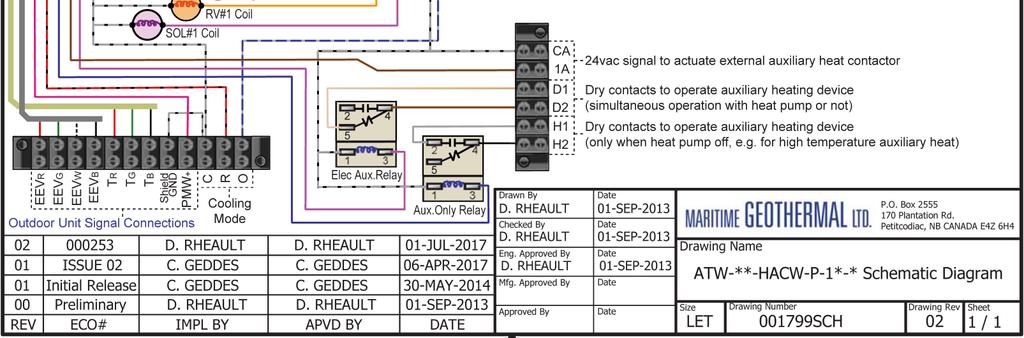
74 Wiring Diagram (208/ ) Page 74

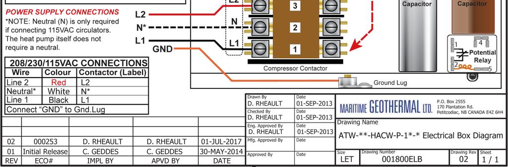
75 Electrical Box Layout (208/ ) Page 75

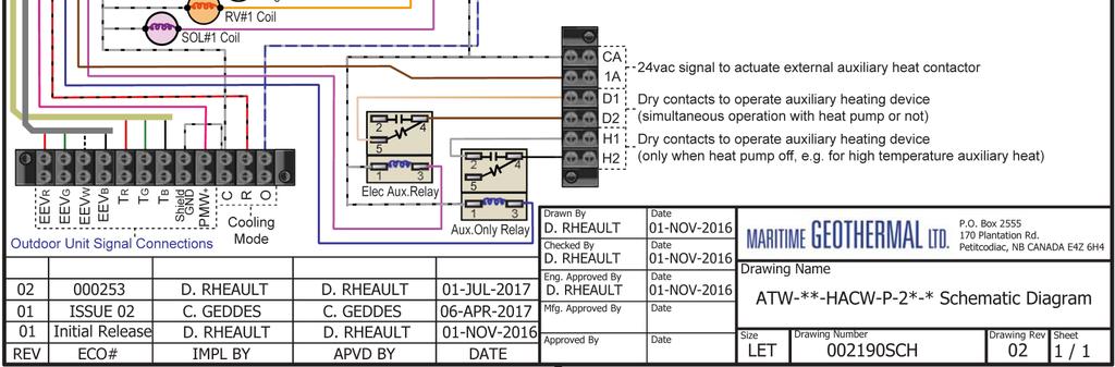
76 Wiring Diagram ( ) Page 76
")
77 Electrical Box Layout ( ) Page 77


78 Wiring Diagram ( ) Page 78
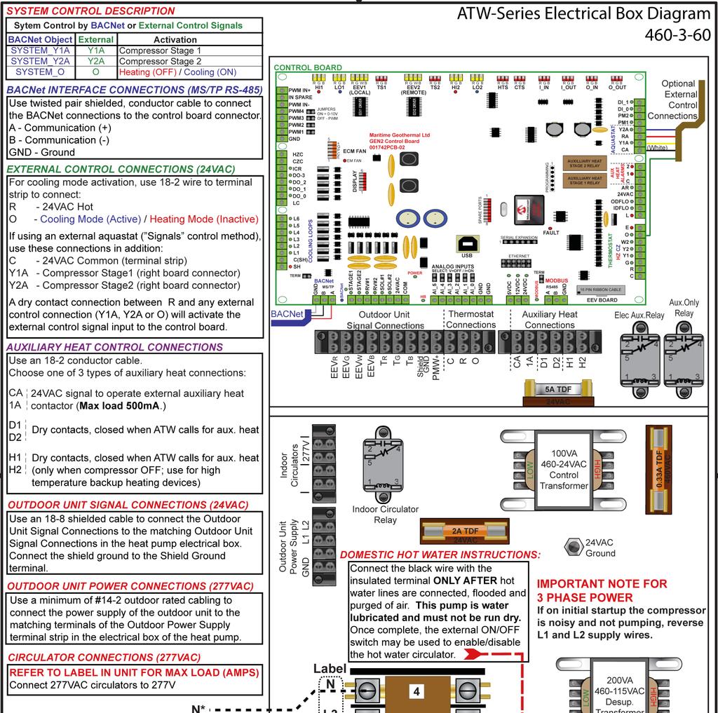
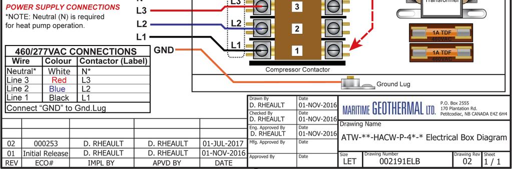
79 Electrical Box Layout ( ) Page 79

80 Page 80
81 Page 81
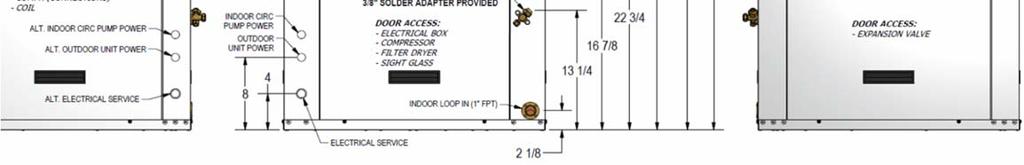
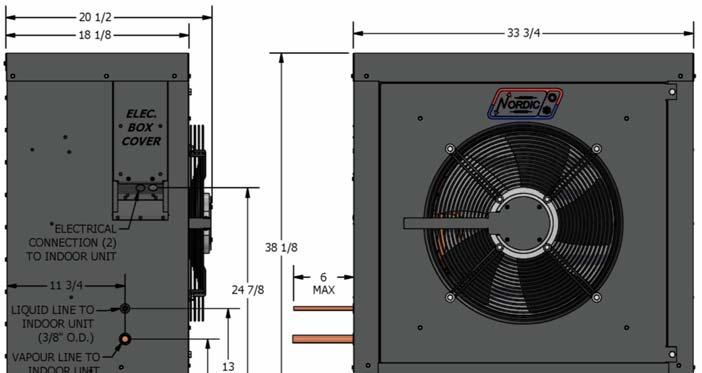
82 Dimensions: ATW-25/45 Page 82
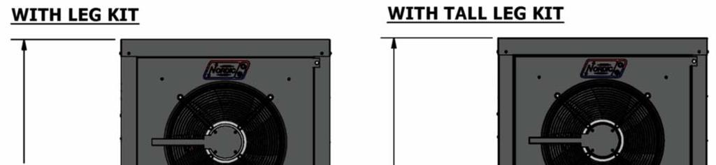
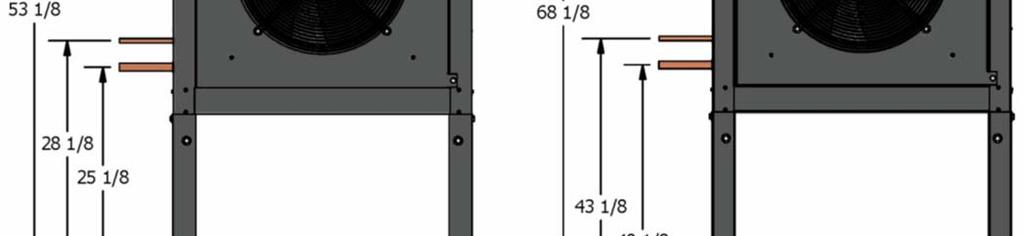
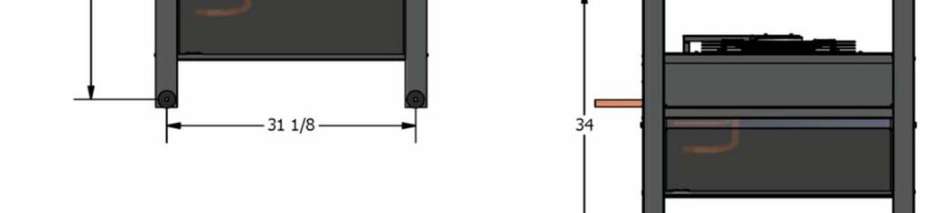
83 Dimensions: ATW-25/45 Page 83

84 Dimensions: ATW-55 Page 84

85 Dimensions: ATW-55 Page 85
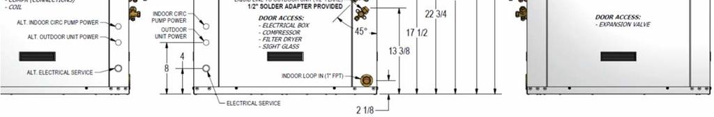
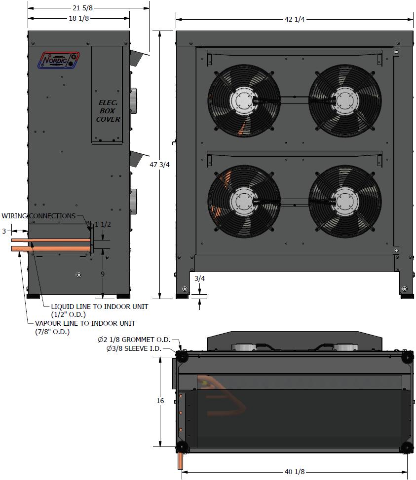
86 Dimensions: ATW-65/75 Page 86

87 Dimensions: ATW-65/75 Page 87

88 Appendix A: Gen2 Control Board Description The picture below shows the locations of the connectors and LED indicators of the control board. The control board offers many features such as short circuit protection on all digital outputs, Real Time Clock with super capacitor for backup power, WiFi capability, relay outputs for plenum heater control (if equipped), USB port, PIC32 microcontroller, etc. High Pressure1 Sensor Connector Low Pressure1 Sensor Connector Suction Line1 Temperature Probe Connector Suction Line2 Temperature Probe Connector High Pressure2 Sensor Connector Low Pressure2 Sensor Connector Temperature Auto Calibration Connector High Pressure1 Fault Indicator Low Pressure1 Fault Indicator Local (Indoor) EEV1 Connector Remote (Outdoor) EEV2 Connector High Pressure2 Fault Indicator Low Pressure2 Fault Indicator Outdoor Temperature Probe Connector Temperature Connectors INDOOR OUTDOOR IN OUT IN OUT Digital Outputs Indoor Fan Connector Aquastat Connections (Optional) PWM Channels (4 out 1 in) Thermostat Connections Digital Inputs Flow Switches Phase Monitors Plenum Heat Airflow Reduction BACnet MS/TP Connector Digital Outputs Heartbeat (flashes once per second) Analog Inputs AI0 to AI5 5VCD 12VDC 24VDC power indicators WiFi Connector Fault Indicator LCD Display Connector Short Circuit Protectors 24VAC Power Indicator USB Connector Power supplies for external sensors for use with Analog Inputs AI0 to AI5 MODBUS MS/TP Connector Page 88
 Signal Description HPS1 High Pressure Sensor 1 Mounted in Indoor Unit, measures discharge pressure.")
89 Below is a picture of the control board. The tables following this picture describe the connections starting with the top of the board and working around the board counter clock-wise. TABLE 35 - Control Board Connector Descriptions (Top) Signal Description HPS1 High Pressure Sensor 1 Mounted in Indoor Unit, measures discharge pressure. LPS1 Low Pressure Sensor 1 Mounted in Indoor Unit, measures suction pressure. EEV1 Local EEV Mounted in Indoor Unit, used in cooling mode. TS1 Suction Line Temperature 1 Mounted to suction line inside unit. EEV2 Remote EEV Mounted in Outdoor Unit, used in heating mode. TS2 Suction Line Temperature 2 Unused. HPS2 High Pressure Sensor 2 Unused. LPS2 Low Pressure Sensor 2 Unused. HTS Outdoor Temperature Mounted in Outdoor Unit. CTS Auto Calibration Resistor in connector for auto-calibration reference (32 F 0 C). I_IN Indoor Loop IN Mounted to pipe inside unit. I_OUT Indoor Loop OUT Mounted to pipe inside unit. O_IN Outdoor Loop IN Unused. O_OUT Outdoor Loop OUT Unused. Page 89
90 TABLE 36 - Control Board Connector Descriptions (Left Side) Name Description PWM_IN Signal for PWM IN Unused. IN_SPARE Spare digital input Unused. COM_IN Common for PWM IN Unused. PWM4 PWM / 0-10VDC output Unused. PWM3 PWM / 0-10VDC output Unused. PWM2 PWM / 0-10VDC output Unused. PWM1 PWM / 0-10VDC output Outdoor Fan PWM control signal. GND Ground Ground for PWM channels. HZC Hot Zone Circulator Unused. CZC Cold Zone Circulator Unused. ICR Internal Circulator Relay Operates the Indoor Circulator. DO_3 Digital output Unused. DO_2 Hydronic Auxiliary Operates the hydronic auxiliary, pins CA and 1A (Setpoint control only). DO_1 Digital output Unused. DO_0 Digital output Unused. LC Loop common (ground) Unused. L6 Loop6 Unused. L5 Loop5 Unused. L4 Loop4 Unused. L3 Loop3 Unused. L2 Loop2 Unused. L1 Loop1 Unused. C(SH) Soaker Hose common Unused. SH Soaker Hose Unused. Page 90
91 TABLE 37 - Control Board Connector Descriptions (Bottom) Name Description GND BACnet MS/TP Ground for shield if required. B BACnet MS/TP RS-485. A BACnet MS/TP RS-485. STAGE1 Compressor Stage 1 Starts / stops the compressor. STAGE2 Compressor Stage 2 Turns on/off the compressor Stage 2 solenoid. RV_#1 Reversing Valve#1 Off in heating mode, on in cooling mode. RV_#2 Reversing Valve#2 Unused. SOL#1 Solenoid#1 On when unit operating, off when unit is off (prevents refrigerant migration). SOL#2 Solenoid#2 Unused. 24VAC Power supply for board 24VAC power for control board. COM Power supply for board GND for control board. AI_5 Analog In Channel 5 0 to 5VDC or 4-20mA user settable with board jumper. AI_4 Analog In Channel 4 0 to 5VDC or 4-20mA user settable with board jumper. AI_3 Analog In Channel 3 0 to 5VDC or 4-20mA user settable with board jumper. AI_2 Analog In Channel 2 0 to 5VDC or 4-20mA user settable with board jumper. AI_1 Analog In Channel 1 0 to 5VDC or 4-20mA user settable with board jumper. AI_0 Analog In Channel 0 0 to 5VDC or 4-20mA user settable with board jumper. GND Ground pin Ground for analog sensors. GND Ground pin Ground for analog sensors. 5VDC Power for analog sensors Provides 5VDC power supply for sensors. 12VDC Power for analog sensors Provides 12VDC power supplu for sensors. 24VDC Power for analog sensors Provides 24VDC power supply for sensors. A MODBUS RS-485. B MODBUS RS-485. GND MODBUS Ground for shield if required. Page 91
92 TABLE 38 - Control Board Connector Descriptions (Right Side) Signal Description DI_1 Digital Input1 Unused. DI_0 Digital Input0 Unused. PM2 Phase Monitor2 Unused. PM1 Phase Monitor1 Accessory for 3 phase models. Y2A* Aquastat Stage2 Used only for external aquastat control. RA* Aquastat Power (24VAC) Used only for external aquastat control. Y1A* Aquastat Stage1 Used only for external aquastat control. CA* Aquastat Power (Ground) Used only for external aquastat control. 2 Plenum Heat Stage2 Unused. 1 Plenum Heat Stage1 Unused. C Plenum Heat Common Unused. AR Ariflow Reductions Unused. 24VAC Power Accessory. ODFLO Outdoor Flow Switch Unused. IDFLO Indoor Flow Swtich Accessory. L Thermostat Lockout Indicator Unused. E Thermostat Emergency Heat Unused. O Thermostat Heat/Cool Unused. W2 Thermostat Auxiliary Heat Unused. Y2 Thermostat Stage2 Unused. Y1 Thermostat Stage1 Unused. G Thermostat Fan Unused. R Thermostat Power (24VAC) Unused. C Thermostat Power (Ground) Unused. *NOTE: There is no need for an external aquastat for most systems, the Setpoint Control Method provides built in aquastat functionality. Page 92


93 Appendix B: PC Software Installation The PC Application MGL GEN2 PC APP is compatible with the following systems: Windows 10 Windows 8 Windows 7 Windows Vista Windows XP Service Pack 2 Here are the installation steps for the PC APP, with screenshots from Windows XP. NOTE: An internet connection may be required if your computer does not already have Miscrosoft Visual Basic Power- Paks 10.0 or.net Framework. 1. Copy MGL GEN2 PC APP Vxxx.zip (or.rar) to the desktop. 2. Double click it to open the zip file. 3. Double click setup.exe. If the file was received via then it may be named setup.abc, if so, change it back to.exe first. 4. The following window may appear asking to install Microsoft Visual Basic PowerPaks If it does, click on Accept to download and install the power packs. NOTE: If you already have an earlier version of Power- Paks installed, you may need to upgrade to Power- Paks10 for the application to work. 5. The following may appear asking to install.net Framework. Click Accept. A re-start may be required once Framework has installed; if asked to reboot click YES. Continue once Windows starts again, you may have to run setup.exe again. 6. The following window should appear; click on Install. 7. The installation will complete and the program should launch afterwards. Page 93


94 Appendix C: USB Driver Setup The PC Application MGL GEN2 PC APP is compatible with the following systems: Windows 10 Windows 8 Windows 7 Windows Vista Windows XP Service Pack 2 Here are the installation steps for the USB driver, with screenshots from Windows XP. 1. Copy MGL GEN2 USB INSTALLER.zip (or.rar) to the desktop. 2. Double click it to open the zip file. 3. Double click on the MGL GEN2 USB Installer folder. 4. Verify that there is a file named USBDriverInstaller.exe. If the file was received via then it may be named USBDriverInstaller.abc, if so, change it back to.exe. 5. Close the zip(or rar) file and then right click and Extract Here. This will place the MGL GEN2 USB Installer folder on the desktop. 6. Connect the a USB cable between the control board and the PC. The Found New Hardware window should appear. 9. Click Next. The following window should appear. 10. Once the following window appears, click Finish to complete the install. The USB connection should now work properly. 7. Select Install from a list or specific location (Advanced) and then click Next. 8. Select Include this location in the search and then click Browse and select the MGL GEN2 USB Installer folder from the Desktop. Page 94


95 Appendix D: Updating Firmware Following are step by step instructions to update the firmware in the control board to the latest release. The firmware comes as a ZIP file named: MGT GEN2 Bootload Firmware Vxxx.zip where xxx is the version reference, e.g. 245 (in this example, version 2.45; this will be used for the remainder of this procedure). This file can be downloaded from 6. Turn the power back on. The control board is now in boot loader mode and is ready to be programmed. 7. Run PIC32UBL.exe. Click on the USB Enable check box. The screen should look like the picture below. 1. Download the file to your PC. We recommend creating a folder like the following: Desktop\MGT GEN2 Bootload Firmware\V Unzip the file in the created folder. There will be two files: The firmware file: MGT_GEN2_V245.production.hex The programmer: PIC32UBL.exe 3. Connect a USB cable to the control board. 4. Turn the power off to the unit. 5. Remove one of the black pin jumpers from just below the USB connector on the board and place in on the center pin pair of the EXPANSION header as shown below. 8. Click on Connect. Remove a jumper from here. 9. Click on Load Hex File. Select the MGT_GEN2_V245.prod uction,hex file. 10. Programming Place jumper here. 11. Programmed and verified. Click on Disconnect and then close the program. 12. Turn the power off. 13. Move the jumper back to where it was taken from. 14. Turn the power back on. Check that the LCD Display shows MGT GEN2 V2.45 on the top line. Page 95
 FIVE YEARS after the date of installation or for a period of (5) FIVE YEARS")
 TWO YEARS from said date. MARITIME GEOTHERMAL LTD.")
96 LIMITED RESIDENTIAL WARRANTY MARITIME GEOTHERMAL LTD. warrants that the heat pumps manufactured by it shall be free from defects in materials and workmanship for a period of (5) FIVE YEARS after the date of installation or for a period of (5) FIVE YEARS AND (60) SIXTY DAYS after the date of shipment, whichever occurs first. In addition MARITIME GEOTHERMAL LTD. warrants that the compressor shall be free of defects in materials and workmanship for an additional period of (2) TWO YEARS from said date. MARITIME GEOTHERMAL LTD. shall, at its option repair or replace any part or parts covered by this warranty which shall be returned to MARITIME GEOTHERMAL LTD., transportation charges prepaid, which, upon examination proves to be defective in materials or workmanship. Replacement or repaired parts and components are warranted only for the remaining portion of the original warranty period. This warranty is subject to the following conditions: 1. The NORDIC heat pump must be properly installed and maintained in accordance with MARITIME GEOTHERMAL LTD.'s installation and maintenance instructions. 2. The installer must complete the Installation Data Sheet, have it endorsed by the owner and return it to Maritime Geothermal Ltd. within 21 days of installation of the unit. 3. It is the responsibility of the building or general contractor to supply temporary heat to the structure prior to occupancy. These heat pumps are designed to provide heat only to the completely finished and insulated structure. Start-up of the unit shall not be scheduled prior to completion of construction and final duct installation for validation of this warranty. 4. It is the customer's responsibility to supply the proper quantity and quality of water. If the heat pump, manufactured by MARITIME GEOTHERMAL LTD., fails to conform to this warranty, MARITIME GEOTHERMAL LTD.'s sole and exclusive liability shall be, at its option, to repair or replace any part or component which is returned by the customer during the applicable warranty period set forth above, provided that (1) MARITIME GEOTHERMAL LTD. is promptly notified in writing upon discovery by the customer that such part or component fails to conform to this warranty. (2) The customer returns such part or component to MARITIME GEOTHERMAL LTD., transportation charges prepaid, within (30) thirty days of failure, and (3) MARITIME GEOTHERMAL LTD.'s examination of such component shall disclose to its satisfaction that such part or component fails to meet this warranty and the alleged defects were not caused by accident, misuse, neglect, alteration, improper installation, repair or improper testing. Page 96
Installation and Service Manual
 Installation and Service Manual TF-Series Triple Function Geothermal Heat Pump (Gen2) Two-stage R410a Model Sizes 45-80 Maritime Geothermal Ltd. P.O. Box 2555, 170 Plantation Road Petitcodiac, NB E4Z 6H4
Installation and Service Manual
 Installation and Service Manual W-Series Liquid to Water Geothermal Heat Pump Two-Stage R410a Model Sizes 25-80 Maritime Geothermal Ltd. P.O. Box 2555 Petitcodiac, NB E4Z 6H4 (506) 756-8135 Email: info@nordicghp.com
Installation and Service Manual. Hydronic Geothermal Heat Pumps
 Installation and Service Manual Boreal W-Series (HW) Model Size 100 (9 Ton) R410a Hydronic Geothermal Heat Pumps Boreal Geothermal Inc. Phone : 450-534-0203 Fax : 450-534-1864 Email: info@boreal-geothermal.com
Installation and Service Manual
 Installation and Service Manual RS-Series Modular Design Split System Compressor Unit Two-Stage R410a Model Sizes 25-75 Liquid to Air Split System Compressor Unit Maritime Geothermal Ltd. P.O. Box 2555
Installation and Service Manual
 Installation and Service Manual WD-Series Wall Mounted Domestic Hot Water Water-Source Heat Pump R134a 60Hz Maritime Geothermal Ltd. P.O. Box 2555, 170 Plantation Road Petitcodiac, NB E4Z 6H4 (506) 756-8135
ENGINEERING SPECIFICATIONS
 ENGINEERING SPECIFICATIONS RH-24-HAC-P-1L-C-SDE*F Horizontal Single Stage R410a Model Size 24 Reversing (Heating AND Cooling) 208/230-1-60VAC Liquid to Air Geothermal Heat Pumps Maritime Geothermal Ltd.
ENGINEERING SPECIFICATIONS
 ENGINEERING SPECIFICATIONS RH-12-HAC-P-1L-C-SDE*F Horizontal Single Stage R410a Model Size 12 Reversing (Heating AND Cooling) 208/230-1-60VAC Liquid to Air Geothermal Heat Pumps Maritime Geothermal Ltd.
Condensing Unit Installation and Operating Instructions
 Bulletin WCU_O&I 01 June 2003 Condensing Unit Installation and Operating Instructions WCU Air Cooled Condensing Unit Table of Contents Section 1. Section 2. Section 3. Section 4. Section 5. Section 6.
PRE-ASSEMBLED RADIANT CONTROL PANEL INSTALLATION MANUAL
 FloorHeat PRE-ASSEMBLED RADIANT CONTROL PANEL INSTALLATION MANUAL Thank you for purchasing this radiant control panel assembly. Following are some important notes that will make the installation successful.
Installation and Service Manual. In-Floor Warming Module external desuperheater for 3rd party air source heat pumps
 Installation and Service Manual IFM-Series In-Floor Warming Module Model Size 48 In-Floor Warming Module external desuperheater for 3rd party air source heat pumps Maritime Geothermal Ltd. P.O. Box 2555
Installation and Service Manual. Heat Recovery Pool Conditioners
 Installation and Service Manual PC-Series Scroll R410a Model Sizes 45-80 Heat Recovery Pool Conditioners Maritime Geothermal Ltd. P.O. Box 2555 Petitcodiac, N.B. E4Z 6H4 Ph. (506)756-8135 Email: info@nordicghp.com
Condensing Unit Installation and Operating Instructions
 Bulletin ACU_O&I 02 August 2016 Condensing Unit Installation and Operating Instructions ACU Air Cooled Condensers Table of Contents Section 1. General Information... 2 Section 2. Refrigeration Piping...
G Series. G Series Air Coils Installation ti Manual ENCASED/UNCASED AIR COILS. Geothermal/Water Source Heat Pumps R-410A Refrigerant 2-5 Ton
 G Series ENCASED/UNCASED AIR COILS Geothermal/Water Source Heat Pumps R-410A Refrigerant 2- Ton Dimensional Data G Series Air Coils Installation ti Manual Installation Information Maintenance IM1018AG1
Engineering Specification
 Engineering Specification ATW-25-HACW-P-*T-* Air to Water Heat Pump 60 Hz Maritime Geothermal Ltd. P.O. Box 2555, 170 Plantation Road Petitcodiac, NB E4Z 6H4 (506) 756-8135 info@nordicghp.com www.nordicghp.com
Engineering Specification
 Engineering Specification WH-55-H-B-*S-** High Temperature Water to Water Heat Pump 60 Hz Maritime Geothermal Ltd. P.O. Box 2555, 170 Plantation Road Petitcodiac, NB E4Z 6H4 (506) 756-8135 info@nordicghp.com
Engineering Specification
 Engineering Specification WH-85-H-B-*S-PD High Temperature Water to DHW Heat Pump 60 Hz Maritime Geothermal Ltd. P.O. Box 2555, 170 Plantation Road Petitcodiac, NB E4Z 6H4 (506) 756-8135 info@nordicghp.com
DLCLRA. INSTALLATION INSTRUCTIONS Outdoor Unit Single Zone Ductless System Sizes 36 to 58 TABLE OF CONTENTS
 DLCLRA INSTALLATION INSTRUCTIONS Outdoor Unit Single Zone Ductless System Sizes 36 to 58 Fig. 1 - Size 36 TABLE OF CONTENTS PAGE SAFETY CONSIDERATIONS... 2 PARTS LIST... 3 SYSTEM REQUIREMENTS... 4 WIRING...
INSTALLER'S GUIDE. ALL phases of this installation must comply with NATIONAL, STATE AND LOCAL CODES
 11-AC11D2-5 INSTALLER'S GUIDE ALL phases of this installation must comply with NATIONAL, STATE AND LOCAL CODES Models: Condensing Units 2A7A5024-048, 2A7A4018-060, 2A7A2018-060 & 2A7A1018-060 IMPORTANT
ENGINEERING SPECIFICATIONS
 ENGINEERING SPECIFICATIONS W-75-HACW-P-1T-** Liquid to Water Geothermal Heat Pump Two-Stage R410a 208/230-1-60 Maritime Geothermal Ltd. P.O. Box 2555 Petitcodiac, NB E4Z 6H4 (506)756-8135 Email: info@nordicghp.com
Engineering Specification
 Engineering Specification WC-55-H-C-*D-** High Temperature Cascade Water to Water Heat Pump 60 Hz Maritime Geothermal Ltd. P.O. Box 2555, 170 Plantation Road Petitcodiac, NB E4Z 6H4 (506) 756-8135 info@nordicghp.com
EarthLinked CC Series Compressor Unit R-410A Quik-Start Instructions
 EarthLinked CC Series Compressor Unit R-410A Quik-Start Instructions CONTENTS PAGE Pre-Installation 3 Placement & Mechanical Information 4 System Application Options 11 Desuperheater Kit 15 Anti-Freeze
CROWN. Boiler Co. Santa-Fe Series. Hydronic Air Handlers INSTALLATION, OPERATION & MAINTENANCE INSTRUCTIONS
 CROWN Boiler Co Santa-Fe Series Hydronic Air Handlers INSTALLATION, OPERATION & MAINTENANCE INSTRUCTIONS These instructions must be affixed on or adjacent to the air handler Models: SAC049A20 SAC059A25
R.A.S.E.R.S System. Installation Guide
 R.A.S.E.R.S System Installation Guide Contents R.A.S.E.R.S System components... 1 Required components for heating, cooling, and hot water...1 Provided...1 Not provided...2 Optional components...3 R.A.S.E.R.S
INSTALLATION INSTRUCTIONS TXV Horizontal Slab Coils WLSH
 TXV Horizontal Slab Coils WLSH These instructions must be read and understood completely before attempting installation. It is important that the Blower and Duct System be properly sized to allow the system
EarthLinked SW Series Compressor Unit R-410A Quik-Start Instructions
 EarthLinked SW Series Compressor Unit R-410A Quik-Start Instructions CONTENTS PAGE Pre-Installation 3 Placement & Mechanical Information 4 System Application Options 10 Antifreeze Protection 14 Electrical
Engineering Specification
 Engineering Specification ATW-45-HACW-P-*T-* Air to Water Heat Pump 60 Hz Maritime Geothermal Ltd. P.O. Box 2555, 170 Plantation Road Petitcodiac, NB E4Z 6H4 (506) 756-8135 info@nordicghp.com www.nordicghp.com
Installation Instructions
 38MHR Outdoor Unit Single Zone Ductless System Sizes 09 to 24 Installation Instructions NOTE: Read the entire instruction manual before starting the installation. NOTE: Images are for illustration purposes
Engineering Specification
 Engineering Specification ATW-65-HACW-P-*T-* Air to Water Heat Pump 60 Hz Maritime Geothermal Ltd. P.O. Box 2555, 170 Plantation Road Petitcodiac, NB E4Z 6H4 (506) 756-8135 info@nordicghp.com www.nordicghp.com
Horizontal/Side Discharge Condensing Units
 INSTALLATION, OPERATION & MAINTENANCE MANUAL Horizontal/Side Discharge Condensing Units Models CMA12SD-0 CMA18SD-1 CMA24SD-1 CMA30SD-1 CMA36SD-1 CMA48SD-1 517.787.2100 www.marsdelivers.com Horizontal/Side
WineZone Ceiling Mount Ductless Split 15
 WineZone Ceiling Mount Ductless Split 15 Requires an HVAC technician to install and charge with R-22 refrigerant. Easy to install. Unit plugs into wall outlet. Industrial grade unit for longer life. Indoor
Installation Instructions
 24AHA4 Performance Series Air Conditioner with Puron Refrigerant 1-1/2 to 5 Nominal Tons Installation Instructions Fig. 1-24AHA4 A07532 SAFETY CONSIDERATIONS Improper installation, adjustment, alteration,
Installation Instructions
 8GXM / 0GXM Multi---Split High---Wall Duct Free Split System 8GXM --- Size 18k, k, and 0k 0GXM --- Size 9k, 1k, and 18k Installation Instructions NOTE: Read the entire instruction manual before starting
INSTALLATION INSTRUCTIONS TXV Horizontal Duct Coils EHD
 TXV Horizontal Duct s EHD These instructions must be read and understood completely before attempting installation. It is important that the Blower and Duct System be properly sized to allow the system
Installation Instructions
 Installation Instructions B-Series VT40, VT60, VT100 Important Safety Notice. This information is intended for use by individuals possessing adequate backgrounds of electrical, refrigeration and mechanical
WMHP Series R410a Heat Pump INSTALLATION INSTRUCTIONS
 WMHP Series R410a Heat Pump INSTALLATION INSTRUCTIONS **WARNING TO INSTALLER, SERVICE PERSONNEL AND OWNER** Altering the product or replacing parts with non authorized factory parts voids all warranty
DLCSRA. INSTALLATION INSTRUCTIONS Outdoor Unit Ductless Split System Sizes 09 to 36 TABLE OF CONTENTS
 DLCSRA INSTALLATION INSTRUCTIONS Outdoor Unit Ductless Split System Sizes 09 to 36 NOTES: Read the entire instruction manual before starting the installation. Images are for illustration purposes only.
INSTALLATION INSTRUCTIONS TXV Horizontal Duct Coils EHD
 TXV Horizontal Duct s EHD These instructions must be read and understood completely before attempting installation. It is important that the Blower and Duct System be properly sized to allow the system
AHG**-0B Series Hydronic Air Handling Units
 HEAT CONTROLLER, INC. Installation, Operation and Maintenance Manual Installation, Operation and Maintenance Manual AHG**-0B Series Hydronic Air Handling Units HEAT CONTROLLER, INC. 1900 Wellworth Ave.,
ECO1ZN3P, ECO2ZN4P ECO
 WARNING HOT This product may have hot fluid circulating through it. DO NOT TOUCH! SOME UNION NUTS MAY BECOME LOOSE AND CONSEQUENTLY LEAK THROUGH TRANSPORTATION VIBRATION AND HANDLING. DO NOT OVERTIGHTEN
INSTALLATION INSTRUCTIONS FOR 6532 SERIES PACKAGE HEAT PUMP
 INSTALLATION INSTRUCTIONS FOR 6532 SERIES PACKAGE HEAT PUMP RV Products A Division of Airxcel, Inc. P.O. Box 4020 Wichita, KS 67204 1976-360 (1-02) PP TABLE OF CONTENTS 1. Warnings......................................................
Service Step by Step Trouble-Shooting Check-List
 WARNING: Only Data Aire trained technician or experience technicians should be working on Data Aire Equipment. Protect yourself at all times and work safe. Date: Dates at the job site: From: to Job#: Serial#:
Installation Instructions
 38MPRA Outdoor Unit Single Zone Ductless System Sizes 09 to 12 Installation Instructions NOTES: Read the entire instruction manual before starting the installation. Images are for illustration purposes
INSTALLATION INSTRUCTIONS TXV Coils for Manufactured Housing EMA
 TXV Coils for Manufactured Housing EMA NOTE: Read the entire instruction manual before starting the installation. SAFETY CONSIDERATIONS Improper installation, adjustment, alteration, service, maintenance,
MODELS B1PA024, 030 AND 036
 STELLAR 2000 SINGLE PACKAGE HEAT PUMPS INSTALLATION INSTRUCTION Supersedes: 511.26-N1Y (892) 511.26-N1Y (893) MODELS B1PA024, 030 AND 036 035-11622 GENERAL YORK Model B1PA units are factory assembled heat
ENGINEERING SPECIFICATIONS
 ENGINEERING SPECIFICATIONS W-150-H-P-*D-PP Vertical Dual Refrigeration Circuit Scroll Compressors R410a Refrigerant Nominal Size 12 Ton Non-Reversing (Heating OR Cooling) Commercial Hydronic Geothermal
PARALLEL RACK SYSTEM INSTALLATION & OPERATIONS MANUAL With Master Rack Compressor Sequencer
 PARALLEL RACK SYSTEM INSTALLATION & OPERATIONS MANUAL With Master Rack Compressor Sequencer 5/16 Rev. A 57-02509 2 Contents INTRODUCTION... 4 WARNING LABELS AND SAFETY INSTRUCTIONS... 5 PS SERIES PARALLEL
CS/CD/CP AIR COOLED CONDENSING UNITS (P/N E207120C R2)
") CS*/CD*/CP* Series Air Cooled Condensing Units Operating and Installation Manual CS/CD/CP AIR COOLED CONDENSING UNITS (P/N E207120C R2) TABLE OF CONTENTS I. Receipt of Equipment 2 II. Piping...4 III. System
CS*/CD*/CP* Series Air Cooled Condensing Units Operating and Installation Manual CS/CD/CP AIR COOLED CONDENSING UNITS (P/N E207120C R2) TABLE OF CONTENTS I. Receipt of Equipment 2 II. Piping...4 III. System
Nordic Heat Pump Product Guide
 Nordic Heat Pump Product Guide About Maritime Geothermal Maritime Geothermal has been manufacturing the Nordic line of geothermal and air source heat pumps for over 30 years. We re committed to manufacturing
User s Information/Installation Instructions
 Outdoor Heat Pump User s Information/Installation Instructions 12 SEER High Efficiency Split System These units have been designed and tested for capacity and efficiency in accordance with A.R.I. Standards.
Heat Transfer Products, Inc. 120 Braley Road East Freetown, MA The first totally integrated multiple boiler management control.
 Heat Transfer Products, Inc. 120 Braley Road East Freetown, MA 02717 The first totally integrated multiple boiler management control. USING THIS MANUAL USING THIS MANUAL A. INSTALLATION SEQUENCE Follow
INSTALLATION INSTRUCTIONS
 INSTALLATION INSTRUCTIONS FOR AQUECOIL HYDRONIC HEATING UNITS GENERAL INFORMATION The AQUECOIL Hydronic Heating Unit is offered in many different capacities and physical configurations in order to match
EarthLinked SCW Series Compressor Unit R-410A Quik-Start Instructions
 EarthLinked SCW Series Compressor Unit R-410A Quik-Start Instructions CONTENTS PAGE Pre-Installation 3 Placement & Mechanical Information 6 System Application Options 12 Antifreeze Protection 13 Electrical
Engineering Specification
 Engineering Specification W-150-H-P-*D-PP Commercial Water to Water Heat Pump Dual Refrigeration Circuit, R410a Nominal Size 12 Ton Non-Reversing Maritime Geothermal Ltd. P.O. Box 2555, 170 Plantation
User s Information and Installation Instructions
 Outdoor Air Conditioner User s Information and Installation Instructions 10 SEER Standard Efficiency Split System These units have been designed and tested for capacity and efficiency in accordance with
INSTALLATION INSTRUCTIONS
 C7BA & C7BH Series Split System Indoor Cased Coils INSTALLATION INSTRUCTIONS IMPORTANT It is your responsibility to know this product better than your customer. This includes being able to install the
Engineering Specification
 Engineering Specification WH-150-H-B-*D-PP High Temperature Water to Water Heat Pump 60 Hz Maritime Geothermal Ltd. P.O. Box 2555, 170 Plantation Road Petitcodiac, NB E4Z 6H4 (506) 756-8135 info@nordicghp.com
Installation Instructions
 PREFERREDT SERIES AIR CONDITIONER WITH PURONR REFRIGERANT 1-1/2 TO 5 NOMINAL TONS Installation Instructions Fig. 1 --- 538A NOTE: Read the entire instruction manual before starting the installation. TABLE
TABLE OF CONTENTS. NOTE: Read the entire instruction manual before starting the installation. TROUBLESHOOTING... 13
 R 410A Duct Free Split System Air Conditioner and Heat Pump Product Family: DFS4(A/H) System, DFC4(A/H)3 Outdoor, DFF4(A/H)H Indoor NOTE: Read the entire instruction manual before starting the installation.
Installation Instructions. For the 18 Built-In Dishwasher and Front Color Panels
 Installation Instructions For the 18 Built-In Dishwasher and Front Color Panels Printed in USA 154232102 Before You Begin DO NOT INSTALL DISHWASHER UNTIL YOU HAVE READ ALL INSTRUCTIONS. FOR YOUR SAFETY,
Engineering Specification
 Engineering Specification WH-400-H-B-*D-PP High Temperature Water to Water Heat Pump 60 Hz Maritime Geothermal Ltd. P.O. Box 2555, 170 Plantation Road Petitcodiac, NB E4Z 6H4 (506) 756-8135 info@nordicghp.com
MULTI-TEMPERATURE LOOP CONTROL BOARD INSTRUCTIONS
 LCB-I-O Rev B MULTI-TEMPERATURE LOOP CONTROL BOARD INSTRUCTIONS Models: KB 81-286, KBXL 400-801, WB 51-211, and WH 55-399 IMG00116 WARNING This manual must only be used by a qualified heating installer
Engineering Specification
 Engineering Specification W-55-HACW-P-1T-** Liquid to Water Geothermal Heat Pump 60 Hz Maritime Geothermal Ltd. P.O. Box 2555, 170 Plantation Road Petitcodiac, NB E4Z 6H4 (506) 756-8135 info@nordicghp.com
Engineering Specification
 Engineering Specification W-25-HACW-P-1T-** Liquid to Water Geothermal Heat Pump 60 Hz Maritime Geothermal Ltd. P.O. Box 2555, 170 Plantation Road Petitcodiac, NB E4Z 6H4 (506) 756-8135 info@nordicghp.com
Engineering Specification
 Engineering Specification W-75-HACW-P-1T-** Liquid to Water Geothermal Heat Pump 60 Hz Maritime Geothermal Ltd. P.O. Box 2555, 170 Plantation Road Petitcodiac, NB E4Z 6H4 (506) 756-8135 info@nordicghp.com
Engineering Specification
 Engineering Specification W-185-H-P-*D-PP Commercial Water to Water Heat Pump Dual Refrigeration Circuit, R410a Nominal Size 17 Ton Non-Reversing Maritime Geothermal Ltd. P.O. Box 2555, 170 Plantation
AVS Air Handlers Installation Manual for Classic SC, SD, and SDH
 AVS Air Handlers Installation Manual for Classic SC, SD, and SDH AVS-NCL-IM (12/15) Copyright 2015 Earthlinked Technologies, Inc. Table of Contents Model Nomenclature... 4 Safety... 5 Equipment Manuals...
EarthLinked HC Series Compressor Unit R-410A Quik-Start Instructions
 EarthLinked HC Series Compressor Unit R-410A Quik-Start Instructions CONTENTS PAGE Pre-Installation 3 Placement & Mechanical Information 4 System Application Options 11 Antifreeze Protection 14 Electrical
Engineering Specification
 Engineering Specification W-600-H-P-*D-PP Commercial Water to Water Heat Pump Dual Refrigeration Circuit, R410a Nominal Size 50 Ton Non-Reversing Maritime Geothermal Ltd. P.O. Box 2555, 170 Plantation
AHWG Remote Mount Hot Water Generator Module for TTP Series Outdoor Split Unit
 A Remote Mount Hot Water Generator Module for TTP Series Outdoor Split Unit Installation, Operation & Maintenance Instructions 97B0080N01 B Table of Contents Model Nomenclature Example 3 Description and
INSTALLATION AND COMMISSIONING MANUAL. Neos 100S Integra 20X, 30S, 35X, 40X, 50X
 Installation Truck Refrigeration & Commissioning Manual: INSTALLATION AND COMMISSIONING MANUAL for Neos 100S Integra 20X, 30S, 35X, 40X, 50X Direct Drive Refrigeration Units 2017 Carrier Corporation Printed
Installation & Operation Manual Models: TSU
 TSU-I-O Rev A Installation & Operation Manual Models: TSU 150-940 CAUTION: This appliance is not intended for potable water. This manual must only be used by a qualified heating installer / service technician.
EBAC MODEL WM150 INDUSTRIAL DEHUMIDIFIER OWNER S MANUAL
 EBAC MODEL WM150 INDUSTRIAL DEHUMIDIFIER OWNER S MANUAL WM150 OWNERS MANUAL Page 1 of 9 INTRODUCTION Designed for a wide range of applications, the WM150 is a rugged, industrial unit, which utilizes an
OWNER S MANUAL. Vintage Classic HEAT COOL models. Proudly Made in the USA
 OWNER S MANUAL Vintage Classic HEAT COOL models Proudly Made in the USA support@aquacomfort.com www.aquacomfort.com/service-and-support 888-475-7443 Manufacturing High Quality, High Efficiency Heat Pump
prestige Control Application Supplement - TriMax
 prestige Control Application Supplement - TriMax L I S T E D WARNING This document is intended to be used by a factory trained and qualified heating contractor or service technician only. Read all instructions
Technical Development Program COMMERCIAL HVAC SYSTEMS. Water Source Heat Pump Systems PRESENTED BY: Ray Chow. Sales Engineer
 Technical Development Program PRESENTED BY: COMMERCIAL HVAC SYSTEMS Water Source Heat Pump Systems Ray Chow Sales Engineer TDP Updates Menu Section 1 Section 2 Section 3 Section 4 Section 5 Section 6 Section
RCM Refrigerant Module
 Small Duct High Velocity Heating, Cooling and Home Comfort Systems RCM Refrigerant Module Installation Manual Manufactured By Module-RCM-Refrigerant-Module-Installation-0666 Refrigerant Modules (RCM) Fig.
AHWG Remote Mount Hot Water Generator Module
 A Remote Mount Hot Water Generator Module For GT-PE (50YPS) Series Outdoor Split Unit Installation, Operation & Maintenance Instructions 97B0080N02 B Model Nomenclature Example 3 Description and Installation
Operation Manual SCT14B and SCT18B. Inspection. 3 General Description. 3 General Requirements. 3 Standard Features.
 Spot Cooling Systems, Inc. 120 Century Drive Suite 00 Carrollton, TX 7006 00-6-776 Operation Manual SCT1B and SCT1B Warning! Improper installation, adjustment, alteration, service, or maintenance can cause
GUIDE SPECIFICATIONS AQUARIUS ii
 Catalog (AP Technical Data Sheet) GUIDE SPECIFICATIONS AQUARIUS ii AP Series Two Stage R-410A GENERAL Units shall be performance certified to ISO standard 13256-1 for Water Loop Pump, Ground Water Pump
T-Series Air Conditioner T15 Model
 INSTRUCTION MANUAL T-Series Air Conditioner T15 Model Protecting Electronics. Exceeding Expectations. McLean Cooling Technology 11611 Business Park Blvd N Champlin, MN 55316 USA Tel 763-323-8200 Fax 763-576-3200
OWNER S MANUAL. Vintage Signature Series models: AC750, AC1050, AC1100, AC1250, AC1500, AC1750. Proudly Made in the USA.
 OWNER S MANUAL Vintage Signature Series models: AC750, AC1050, AC1100, AC1250, AC1500, AC1750 Proudly Made in the USA support@aquacomfort.com 888-475-7443 Manufacturing High Quality, High Efficiency Heat
MULTI-TEMPERATURE LOOP CONTROL BOARD INSTRUCTIONS
 LCB-I-O Rev D MULTI-TEMPERATURE LOOP CONTROL BOARD INSTRUCTIONS Models: KB 81-286, KBXL 400-801, WB 51-211, FTX 400-850 and WH 55-399 WARNING This manual must only be used by a qualified heating installer
R Series Cooling Modules
 TM Small Duct High Velocity Heating, Cooling and Indoor Air Quality Systems R Series Cooling Modules Models RCM-50 RCM-70 RM-100 Manufactured By Module-RCM/RM-Series-Installation-Manual-120113 Refrigerant
INSTALLATION INSTRUCTIONS
 INSTALLATION INSTRUCTIONS C7BA Series Split System Indoor Cased Coils IMPORTANT ATTENTION INSTALLERS: It is your responsibility to know this product better than your customer. This includes being able
UHIR Series. Horizontal or Vertical Mounting Industrial / Commercial Electric Unit Heater. Owner s Manual
 UHIR Series Horizontal or Vertical Mounting Industrial / Commercial Electric Unit Heater Owner s Manual This manual covers installation, maintenance and repair parts. Read carefully before attempting to
RV Products Division INSTALLATION INSTRUCTIONS FOR SERIES PACKAGE AIR CONDITIONER
 RV Products Division INSTALLATION INSTRUCTIONS FOR 46413 SERIES PACKAGE AIR CONDITIONER 1. WARNINGS IMPORTANT NOTICE These instructions are for the use of qualified individuals specially trained and experienced
Installation, Start-Up and Service Instructions
 38AH044-134 Air-Cooled Condensing Units 50/60 Hz Installation, Start-Up and Service Instructions CONTENTS Page SAFETY CONSIDERATIONS...................... 1 INSTALLATION................................
EarthLinked AVN Series Air Handlers Installation Manual
 EarthLinked AVN Series Air Handlers Installation Manual AVN-410-IM (03/14) Copyright 2014 Earthlinked Technologies, Inc. Table of Contents Model Nomenclature... 4 Safety... 5 Equipment Manuals... 5 Installation...
Engineering Specification
 Engineering Specification W-300-HAC-P-*D-PP Commercial Water to Water Heat Pump Dual Refrigeration Circuit, R410a Nominal Size 23 Ton Reversing (Heating or Cooling) Maritime Geothermal Ltd. P.O. Box 2555,
INSTALLATION MANUAL. Split-type Air Conditioner (Cooling and Heating) Outdoor Unit UQB09JJWC UQB12JJWC. Indoor Unit AQB09JJWC AQB12JJWC
 Outdoor Unit UQB09JJWC UQB12JJWC. Indoor Unit AQB09JJWC AQB12JJWC") AQB09JJ6WC_IM_E_2585 2006.4.17 4:26 PM Page 17 INSTALLATION MANUAL Indoor Unit AQB09JJWC AQB12JJWC Outdoor Unit UQB09JJWC UQB12JJWC ENGLISH FRANÇAIS ESPAÑOL Split-type Air Conditioner (Cooling and Heating)
AQB09JJ6WC_IM_E_2585 2006.4.17 4:26 PM Page 17 INSTALLATION MANUAL Indoor Unit AQB09JJWC AQB12JJWC Outdoor Unit UQB09JJWC UQB12JJWC ENGLISH FRANÇAIS ESPAÑOL Split-type Air Conditioner (Cooling and Heating)
User s Information and Installation Instructions
 Outdoor Air Conditioner User s Information and Installation Instructions 13 SEER R-410A High Efficiency Split System These units have been designed and tested for capacity & efficiency in accordance with
INSTALLATION INSTRUCTIONS
 INSTALLATION INSTRUCTIONS STELLAR AIR CONDITIONING UNIT SPLIT-SYSTEM COOLING CONTENTS GENERAL..................................... 2 NOMENCLATURE........................... 2 SAFETY...................................
CAH SERIES INSTALLATION & MAINTENANCE MODELS CAH CAH
 CAH SERIES INSTALLATION & MAINTENANCE MODELS CAH 33-44-50 CAH 49-54-70 CAH VARIABLE SPEED AIR HANDLERS DIMENSIONS... 3 TECHNICAL SPECS... 4 INSTALLATION DON TS... 5 INSTALLATION DO S... 6 FREEZE STAT REQUIRED
R Series Cooling Modules
 R Series Cooling Modules Models RCM/RPM 50 RCM 70 RM 100 RM 140 Manufactured By Energy Saving Products Ltd. Standard ESP 105.03 Refrigerant Modules (RCM/RM) Fig. 02 - Mounting brackets The cooling coil
EBAC MODEL K100 DEHUMIDIFIER OWNER S MANUAL
 EBAC MODEL K100 DEHUMIDIFIER OWNER S MANUAL Ebac Industrial Products 700 Thimble Shoals Boulevard Newport News VA 23606-2575 Telephone (757) 873-6800 Fax (757) 873-3632 Website: www.ebacusa.com INTRODUCTION
User s Information and Installation Instructions
 Outdoor Air Conditioner User s Information and Installation Instructions 2-Stage R-410A Split System These units have been designed and tested for capacity & efficiency in accordance with A.H.R.I. Standards.
OPERATION & MAINTENANCE MANUAL AC860
 OPERATION & MAINTENANCE MANUAL AC860 Refrigerant Handling System Manual P/N 035-80913-00 TABLE OF CONTENTS Startup & Safe Operation... 1 Introduction to the AC860... 2 Control Panel... 3 Keypad Functions...
EarthLinked SC Series Compressor Unit R-407C Quik-Start Instructions
 EarthLinked SC Series Compressor Unit R-407C Quik-Start Instructions CONTENTS PAGE Pre-Installation 3 Placement & Mechanical Information 4 System Application Options 11 Desuperheater Kit 15 Antifreeze
INSTALLATION MANUAL GEO-BOOST GROUND LOOP HEAT EXCHANGER
 1103 N HIGH CROSS RD URBANA, IL 61802 1-773-492-1893 INSTALLATION MANUAL GEO-BOOST GROUND LOOP HEAT EXCHANGER REV 1.0 The Geo-Boost system consists of the Geo-Boost heat exchanger and a relay controller
T-SERIES Air Conditioner. T20 Model INSTRUCTION MANUAL nvent Rev. C P/N
 T-SERIES Air Conditioner T20 Model INSTRUCTION MANUAL Rev. C P/N 89114993 TABLE OF CONTENTS Warranty and Return Policy... 2 IMPORTANT NOTICE... 2 RECEIVING THE AIR CONDITIONER... 3 HANDLING AND TESTING