Installation and Service Manual. Heat Recovery Pool Conditioners
|
|
|
- Quentin Alexander
- 5 years ago
- Views:
Transcription

756-8135 Email: info@nordicghp.com Web: www.")

1 Installation and Service Manual PC-Series Scroll R410a Model Sizes Heat Recovery Pool Conditioners Maritime Geothermal Ltd. P.O. Box 2555 Petitcodiac, N.B. E4Z 6H4 Ph. (506) Web: Document Number: MAN-01 ISSUE 03: 17 NOV 2014 ISSUE 03 Page DATE: 1 17 NOV MAN-01
2 SAFETY PRECAUTIONS!! WARNING: Ensure all access panels are in place and properly secured before applying power to the unit. Failure to do so may cause risk of electrical shock. WARNING: Before performing service or maintenance on the heat pump system, ensure all power sources are DISCONNECTED. Electrical shock can cause serious personal injury or death. WARNING: Heat pump systems contain refrigerant under high pressure and as such can be hazardous to work on. Only qualified service personnel should install, repair, or service the heat pump. CAUTION: Safety glasses and work gloves should be worn at all times whenever a heat pump is serviced. A fire extinguisher and proper ventilation should be present whenever brazing is performed. CAUTION: Venting refrigerant to atmosphere is illegal. A proper refrigerant recovery system must be employed whenever repairs require removal of refrigerant from the heat pump. MODEL NOMENCLATURE PC 65 PG 1S T KDERS xx Series: PC = Pool Conditioner Nominal Size: 45 = 3 Ton 55 = 4 Ton 65 = 5 Ton 80 = 6 Ton Refrigerant: P = R410a Refrigeration Gauges: G = Yes Voltage Code: 1 = VAC 2 = VAC 6 = VAC 7 = VAC Compressor Stages*: S = 1 Stage Revision: 01, 02 etc. Fan Discharge: S = Side T = Top (up) D = Down Fan Return: R = Right Side Fan Motor: E = ECM (Variable Speed) Fan Type: D = Direct Drive Air Coil: K = Coated Indoor Loop (Pool) Exchanger: T = Titanium MAN-01 Page 2 ISSUE 03:17 NOV 2014
3 APPLICATION TABLE SIZE REFRIGERANT REFRIGERANT GAUGES VOLTAGE STAGES INDOOR COIL FAN/CASE REVISIONS 45 P G 55 P G 65 P G 1 S KDERS 06 2 S 06 T KDERT 6 S 06 7 S KDERD 06 1 S KDERS 06 2 S 06 T KDERT 6 S 06 7 S KDERD 06 1 S KDERS 06 2 S 06 T KDERT 6 S 06 7 S KDERD 06 1 S KDERS 06 2 S P G T KDERT 6 S 06 7 S KDERD 06 This manual applies only to the models and revisions listed in this table ISSUE 03: 17 NOV 2014 Page MAN-01
4 Table of Contents TABLES, DIAGRAMS & DRAWINGS: PAGE 5 INSTALLATION INFORMATION:.... PAGE 6 Unit description:..... Page 6 Unpacking the unit:... Page 6 Optimum Placement:. Page 6 Electrical Connections: Page 6 Control Requirements:.... Page 6 Control Mounting Locations:.. Page 7 System Operation (Priority Jumper Placed):.... Page 7 System Operation (Priority Jumper Not Placed):.... Page 10 Fan Motor: Page 13 Control Transformer : Page 13 Safety Controls:. Page 13 Pool Circulator Pump Control:.. Page 13 A/C Option (Outdoor Condenser):.... Page 14 A/C Option (Cold Water):..... Page 14 Exhaust Fan Option:..... Page 14 SIZING AND DUCTWORK:... PAGE 16 Pool Surface Area:. Page 16 PC Unit Sizing:... Page 16 Duct Systems - General:.. Page 18 Supply Duct System:. Page 18 Return Duct System:. Page 18 Plenum Heater (Optional): Page 18 Condensate Drain:.. Page 19 Duct Sizing Guide:. Page 22 STARTUP PROCEDURE:. Page 23 Pre-start Inspection:. Page 23 Unit Startup:... Page 23 Startup Record:.. Page 25 GENERAL MAINTENANCE:.... PAGE 26 TROUBLESHOOTING GUIDE:. PAGE 27 Repair Procedures: Page 38 Refrigeration Circuit Diagrams:..... Page 39 MODEL SPECIFIC INFORMATION:.... PAGE 42 Refrigerant Charge Chart: Page 42 Shipping Information: Page 42 Capacity Ratings: Page 42 Electrical Tables: Page 43 Electrical Diagrams (Controls Connections):.... Page 44 Electrical Diagrams ( ):.. Page 45 Electrical Diagrams ( ):.. Page 47 Case Details:... Page 49 APPENDIX A: Control Board Specifications: PAGE 51 APPENDIX B: ECM Fan Airflow Tables:. PAGE 52 APPENDIX C: Ranco Aquastat Instructions:.... PAGE 53 WARRANTY INFORMATION:.. PAGE MAN-01 Page 4 ISSUE 03:17 NOV 2014
5 Tables, Diagrams and Drawings TABLES Table 1 - Control Signal Description:.... Page 6 Table 2 - Typical PC control settings: Page 7 Table 3 - PC Control System Operation Truth Table (Priority Jumper Placed):.... Page 8 Table 4 - PC Control System Operation Truth Table (Priority Jumper Placed):.... Page 11 Table 5 - Airflow Selections:... Page 13 Table 6 - Control Board Fault Codes: Page 13 Table 7 - Pool Circulator Control Wiring: Page 14 Table 8 - Step by Step Pool Evaporation Rate Calculation: Page 16 Table 9 - Typical PC unit Sizing Guide 60Hz: Page 16 Table 10 - Typical PC unit Sizing Guide 50Hz: Page 17 Table 11 - Evaporation Rate Chart (50% RH) Lbs/Hr - ft 2 : Page 17 Table 12 - Evaporation Rate Chart (60% RH) Lbs/Hr - ft 2 : Page 17 Table 13 - Activity Factor: Page 18 Table 14 - Plenum Heater Sizing: Page 19 Table 15 - Duct Sizing Guide: Page 22 Table 16 - Refrigerant Charge Chart: Page 42 Table 17 - Shipping Information: Page 42 Table 18 - PC Unit Capacity Ratings 60Hz: Page 42 Table 19 - PC Unit Capacity Ratings 50Hz: Page 42 Table 20 - PC Unit Electrical Information ( ): Page 43 Table 21 - PC Unit Electrical Information ( ): Page 43 Table 22 - PC Unit Electrical Information ( ): Page 43 Table 23 - PC Unit Electrical Information ( ): Page 43 DIAGRAMS Diagram A - PC Control System Flow Chart Priority Jumper Placed (without A/C): Page 9 Diagram B - PC Control System Flow Chart Priority Jumper Placed (with A/C): Page 9 Diagram C - PC Control System Flow Chart Priority Jumper Not Placed (without A/C):..... Page 12 Diagram D - PC Control System Flow Chart Priority Jumper Not Placed (with A/C): Page 12 Diagram E - Floor Supply Ducts with Elevated Return: Page 21 Diagram F - Elevated Supply Ducts with Elevated Return: Page 21 Case Details: Page 49 DRAWINGS CDG - PC Unit Cold Water Cooling Connections: Page CDG - Typical Duct and Condensate Connections (PC Unit):..... Page RCD - PC-Series Refrigeration Circuit Diagram - Pool Heat Mode:.... Page RCD - PC-Series Refrigeration Circuit Diagram - Air Re-Heat Mode:.... Page RCD - PC-Series Refrigeration Circuit Diagram - Air Cooling Mode:. Page CDG - PC-Series Controls Connection Diagram for ECM Fan:... Page SCH - PC-**-**-1S-T-*DE** Schematic Diagram: Page ELB - PC-**-**-1S-T-*DE** Electrical Box Diagram: Page SCH - PC-**-**-6S-T-*DE** Schematic Diagram: Page ELB - PC-**-**-6S-T-*DE** Electrical Box Diagram: Page 48 ISSUE 03: 17 NOV 2014 Page MAN-01
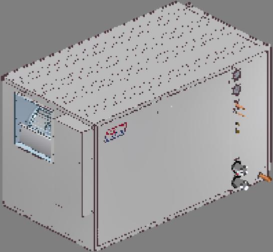
6 UNIT DESCRIPTION The PC-Series unit is a high efficiency heat recovery unit with coated air coils, titanium exchanger and stainless steel case. The unit cools and dehumidifies the pool area and can reject the heat back into the airstream, into the pool, or to an optional external outdoor condenser unit. Installation Information ELECTRICAL CONNECTIONS The PC unit has a concentric / knockout for power supply connection to the electrical box. There are three 1/2 openings with plastic grommets (grommet hole is 3/8 ) in the upper section of the electrical box for connections to the external controls. An electrically commutated (ECM) fan with several speed options is standard. The motor has a soft start function for improved efficiency and reduced wear. The unit contains R410a refrigerant, which is an environmentally friendly refrigerant. R410a is also a more efficient refrigerant than R22 or R407c. The unit has several key features that are described in the specifications document for the particular heat pump. Please request a copy if desired or visit UNPACKING THE UNIT When the heat pump reaches its destination it should be unpacked to determine if any damage has occurred during shipment. Any visible damage should be noted on the carrier's freight bill and a suitable claim filed at once. The heat pump is well constructed and every effort has been made to ensure that it will arrive intact, however it is in the customer's best interest to examine the unit thoroughly when it arrives. OPTIMUM PLACEMENT The placement of a the unit has negligible effects on the operation of the system. The unit can be placed wherever it can most easily be connected to. Generally this is in the pool room or in the mechanical room in order to minimize piping distances. If ductwork is used then it is good practice to center the unit with respect to the ductwork when possible to facilitate air distribution. If possible the access panels should remain clear of obstruction for a distance of two feet to facilitate servicing and general maintenance. Ensure the unit is level to eliminate any possible condensate drain issues. Raising the heat pump off the floor a few inches is generally a good practice since this will prevent rusting of the bottom panel of the unit. We recommend that the heat pump be placed on a piece of 2'' thick styrofoam. The styrofoam will smooth out any irregularities in the cement floor and deaden any compressor noise emitted from the bottom of the cabinet. The unit can also be suspended with a proper rack system able to bear a recommended two times the weight of the unit The unit has an air-filter rack which can be installed with the removable end (where the filter is inserted) on either side to facilitate changing the filter.!! WARNING: It is recommended that pool chemicals be stored away from the unit to prevent any premature corrosion problems. The should not be stored in the same room as the PC unit. WARNING: Pool chemicals should be injected into the system downstream of the PC unit. A schematic diagram and electrical box layout diagram (ELB) can be found inside the electrical box cover of the unit as well as in the Model Specific section of this manual. The Electrical Tables in the Model Specific section and the ELB diagram contain information about the size of wire for the connections, as well as the recommended breaker size. A properly qualified electrician should be retained to make the connections to the heat pump and associated controls. The connections to the heat pump MUST CONFORM TO LOCAL CODES. CONTROL REQUIREMENTS The PC-Series unit comes with the following controls: (2) Two stage aquastats (1) De-humidistat One of the aquastats is used to control the pool room temperature and will be referred to as the Air Aquastat from now on. The other is used to control the pool temperature and will be referred to as the Pool Aquastat. If the A/C option (outdoor condenser unit) is installed then a third two-stage aquastat is required to control the air cooling mode. The electrical diagrams on the electrical box cover provide a description of the signal connections as does TABLE 1. TABLE 1 - Control Signal Description Signal Description C 24VAC Common (Ground) R 24VAC Hot Y Heat Pump (Compressor and fan) O Air re-heat mode F Plenum Heater dry contact F Plenum Heater dry contact C1* 24VAC Common (Ground) for cooling control R1* 24VAC Hot for cooling control O1* Cooling Mode * These signals are only required if the A/C option (outdoor condenser unit) is connected to the PC unit. TABLE 2 shows typical settings for the each of the controls. These are the recommended settings. The setpoints may be adjusted as desired but there are a few rules that must be observed for proper system operation: Air Aquastat delta s should not be set larger than the values in the table. Pool Aquastat Stage 1setpoint should not be any more that 2 F below the Air Aquastat Stage 1 setpoint. Air Cooling Aquastat setpoints must be equal to (preferred) or higher than the Air Aquastat Stage 1 setpoint. Air Cooling Aquastat Stage 1 and Stage 2 setpoints and delta s must be set identical MAN-01 Page 6 ISSUE 03:17 NOV 2014
7 TABLE 2 - Typical PC Control Settings AIR AQUASTAT Stage 1 Stage 2 Item F C F C Setpoint Delta 2 1 Activation * AIR COOLING AQUASTAT (IF INSTALLED) Stage 1 ** Stage 2** Item F C F C Setpoint Delta 1 1 Activation * POOL AQUASTAT Stage 1 Stage 2 *** Item F C F C Setpoint (78) Delta 2 2 (1) Activation * (77) DE-HUMIDISTAT Setpoint 55% *Activation is indirectly set by the Setpoint and Delta values **Stage 1 and Stage 2 setpoint and Delta values must be identical for the Air Cooling Aquastat. *** 80 and 2 if Priority Jumper is placed (must be identical to Stage 1 values) CONTROL MOUNTING LOCATIONS The De-humidistat, Air Aquastat and Air Cooling Aquastat (if installed) should be mounted close to one another in the pool room, at a recommended height of 4ft to 5ft. They should be placed in a location that is away from any splashing to prevent accidental damage to them. They should not be placed directly in the path of any supply registers. Doing so can yield values that are not representative of the conditions of the room and can cause short-cycling. The probes of the aquastats can be neatly strapped up. The Pool Aquastat can be mounted by itself or with the others. The probe should be placed in a dry-well in the Indoor IN line to the heat pump. If a dry well is not available then the probe can be strapped to the outside of the pipe, but ensure it is well insulated at least 6 at each end of it (refer to CDG-03). SYTEM OPERATION (PRIORITY JUMPER PLACED) The primary purpose of the pool conditioner unit is to maintain proper humidity levels in the pool room. During this operation energy is removed from the air and can be rejected to either to the pool water, the pool room air, or optionally to an outdoor condenser unit. TABLE 3 contains a truth table which indicates which modes are active based on the control signals. Diagram A and Diagram B contain flow charts that indicate the control sequence as well. There are three methods in which the PC unit can be activated: 1) Call from the de-humidistat because the humidity level has risen above the desired setpoint 2) Call from the Pool Aquastat because the pool temperature has dropped below the desired setpoint. 3) Call from the Air Aquastat because the temperature in the room has dropped below the desired setpoint. The modes of operation for each of these activation methods are described below. 1) UNIT ACTIVATED BY DE-HUMIDISTAT A) Without A/C option: With no other controls active, RV#1 is active and the default rejection mode is air re-heat (refer to RCD). In this mode the energy extracted from the dehumidification process is injected back into the pool room air along with the compressor and fan energy, for a net energy increase equal to the compressor and fan electrical consumption. In this mode the air is dehumidified and heated at the same time. This can lead to overheating the room in some cases if the pool room temperature is satisfied and the pool water is satisfied. If it is suspected that this may occur due to the climate of the region, then an outdoor condenser unit (A/C option) is recommended in order to reject the unwanted heat (see A/C OPTION (OUTDOOR CONDENSER). The unit will shut off once the dehumidification setpoint has been reached. If the pool water temperature drops down to the Pool Aquastat Stage 1 / Stage 2 (must be identical) activation point, the unit will override the air-reheat mode and pool heat mode is activated. The air-reheat mode will remain locked out until the Pool Aquastat Stage 1 / Stage 2 setpoint (must be identical) is reached. The plenum heater will still operate during this time if the pool room air temperature drops to the Air Aquastat Stage 2 activation point. B) With A/C option: Operation of the system with the A/C option is the same as in section A except for when the pool room air temperature is above the Air Cool Aquastat activation points. This also implies that the pool room temperature is above the Air Aquastat Stage 1 setpoint (refer to controls). The Air Cool Aquastat engages both RV#1 and RV#2 to enable air cooling mode (refer to RCD). If there is a call for dehumidification and the air temperature is above or equal to the Stage 1 activation point of the Air Cool Aquastat, the absorbed energy from the pool room air will be discarded outside via the outdoor condenser unit instead of being rejected into the air or pool. This allows the pool room to be de-humidified and cooled. The Air Cool Aquastat Stage 1 and Stage 2 setpoints must be identical and must be equal to or higher than the Air Aquastat Stage 1 setpoint. Once the Air Cool Aquastat setpoints have been reached the unit will revert back to air or pool water mode. Operation after this is identical to that described in section A. 2) UNIT ACTIVATED BY POOL AQUASTAT STAGE 1/2 In this scenario the de-humidistat is satisfied but the pool water temperature dropped to the Stage 1 activation point of the Pool Aquastat. The unit will operate in pool heat mode and begin dehumidifying / cooling the pool room and heating the pool water. If during this time the Stage 2 activation point of the Air Aquastat is reached, the plenum heater will engage to reheat the air. The plenum heater operates independently of the PC unit and will remain on until Stage 2 setpoint is reached even if the PC unit cycles off. Note that if the PC unit does cycle ISSUE 03: 17 NOV 2014 Page MAN-01
8 off during this time, the fan will remain on until Stage 2 setpoint has been reached and the plenum heater shuts off. 3) UNIT ACTIVATED BY AIR AQUASTAT STAGE 1 In this scenario the de-humidistat is satisfied and the Pool Aquastat is satisfied but the air temperature has dropped to the Stage 1 activation point of the Air Aquastat. The unit will start and operate in air-reheat heat mode and begin dehumidifying / re-heating the pool room. If during this time the Stage 2 activation point of the Air Aquastat is reached, the plenum heater will engage to help re-heat the air. The plenum heater operates independently of the PC unit and will remain on until Stage 2 setpoint is reached even if the PC unit cycles off. De- Humidistat TABLE 3 - PC Control System Operation Truth Table (Priority Jumper Placed) Air Aquastat CONTROLS* Pool Aquastat Air Cool Aquastat STAGE 1 STAGE 1 STAGE 2 STAGE 1 STAGE 2 STAGE 1 Plenum Heater SYSTEM OPERATION Air Re-Heat Pool Water X X X X X X X X X X X X X X X X X X X X X X X X X X X X X X X X X X X X X X X X X X X X X Outdoor Condenser X X X X X** X X X X** X** X X X X X** X** X X X X X X X X X X X X** X X X X X** X X X** X** X X X** X** X X X X X X X X X X** X X X X * Dehumidification occurs anytime the unit is operational. **Ensure the cooling setpoint is equal to or higher than the heating setpoint to avoid these conditions. Ccooling has priority should these conditions occur, but the plenum heater will still activate anytime Air Aquastat Stage 2 is on MAN-01 Page 8 ISSUE 03:17 NOV 2014
9 DIAGRAM A - PC Control System Flow Chart Priority Jumper Placed (without A/C) Dehumidistat Pool Aquastat STAGE 1 & 2 Air Aquastat STAGE 1 Air Aquastat STAGE 2 ON OFF ON ON OFF OFF ON Pool Water Heat Mode Electric Plenum Heat AND PC Unit OFF OR Air Re-heat Mode DIAGRAM B - PC Control System Flow Chart Priority Jumper Placed (with A/C) Dehumidistat Pool Aquastat STAGE 1 & 2 Air Aquastat STAGE 1 Air Aquastat STAGE 2 OFF ON ON OFF OFF ON ON Electric Plenum Heat AND Air Cool Aquastat STAGE 1 & 2 PC Unit OFF OR ON Air Re-heat Mode Pool Water Heat Mode OR AND A/C Mode ISSUE 03: 17 NOV 2014 Page MAN-01
10 SYTEM OPERATION (PRIORITY JUMPER NOT PLACED) The primary purpose of the pool conditioner unit is to maintain proper humidity levels in the pool room. During this operation energy is removed from the air and can be rejected to either to the pool water, the pool room air, or optionally to an outdoor condenser unit. TABLE 4 contains a truth table which indicates which modes are active based on the control signals. Diagram C and Diagram D contain flow charts that indicate the control sequence as well. There are two methods in which the PC unit can be activated: 1) Call from the de-humidistat because the humidity level has risen above the desired setpoint 2) Call from the Pool Aquastat because the pool temperature has dropped below the desired setpoint The modes of operation for each of these activation methods are described below. 1) UNIT ACTIVATED BY DE-HUMIDISTAT A) Without A/C option: With no other controls active, the default rejection mode is pool water (refer to RCD). In this mode the pool room air is dehumidified and cooled while the pool water is heated, regardless of whether or not there is a call from Stage 1of the Pool Aquastat. This can lead to overheating the pool in some cases if the pool room temperature is high enough. If it is suspected that this may occur due to the climate of the region, then an outdoor condenser unit (A/C option) is recommended in order to reject the unwanted heat (see A/C OPTION (OUTDOOR CONDENSER). If the pool room cools down enough to reach the Air Aquastat Stage 1 activation point (activation point = setpoint - delta), RV#1 is energized (refer to RCD) and re-heat mode is activated. In this mode the energy extracted from the dehumidification process is injected back into the pool room air along with the compressor and fan energy, for a net energy increase equal to the compressor and fan electrical consumption. In this mode the air is dehumidified and heated at the same time. The Air Cool Aquastat engages both RV#1 and RV#2 to enable air cooling mode (refer to RCD). If there is a call for dehumidification and the air temperature is above or equal to the Stage 1 activation point of the Air Cool Aquastat, the absorbed energy from the pool room air will be discarded outside via the outdoor condenser unit instead of being rejected into the pool. This allows the pool room to be de-humidified and cooled without the risk of overheating the pool. The Air Cool Aquastat Stage 1 and Stage 2 setpoints must be identical and must be equal to or higher than the Air Aquastat Stage 1 setpoint. Once the Air Cool Aquastat setpoints have been reached the unit will revert back to pool water mode. Operation after this is the identical to that described in section A. 2) UNIT ACTIVATED BY POOL AQUASTAT STAGE 1 In this scenario the de-humidistat is satisfied but the pool water temperature dropped to the Stage 1 activation point of the Pool Aquastat. If no other controls are active then the unit will operate in pool heat mode and begin dehumidifying / cooling the pool room and heating the pool water. If during this time the Stage 1 activation point of the Air Aquastat is reached, air reheat mode will begin. The unit will continue to switch back and forth between air re-heat and pool water heat modes until the Stage 1 setpoint of the Pool Aquastat is reached. If the pool water temperature drops down to Pool Aquastat Stage 2 activation point, the air-reheat mode is locked out and pool heat mode is activated. The air-reheat mode will remain locked out until the Pool Aquastat Stage 2 setpoint is reached. The plenum heater will still operate during this time if the pool room air temperature drops to the Air Aquastat Stage 2 activation point. If the pool room air temperature continues to drop and reaches The Air Aquastat Stage 2 activation point, the plenum heater will activate. The plenum heater operates independently of the PC unit and will remain on until Stage 2 setpoint is reached even if the PC unit cycles off. Note that if the PC unit does cycle off during this time, the fan will remain on until Stage 2 setpoint has been reached and the plenum heater shuts off. If the pool room air temperature continues to drop and reaches The Air Aquastat Stage 2 activation point, the plenum heater will activate. The plenum heater operates independently of the PC unit and will remain on until Stage 2 setpoint is reached even if the PC unit cycles off. Note that if the PC unit does cycle off during this time, the fan will remain on until Stage 2 setpoint has been reached and the plenum heater shuts off. If the pool water temperature drops down to the Pool Aquastat Stage 1 activation point, the unit will remain in air re-heat mode if Stage 1 of the Air Aquastat is still active. If the pool water temperature drops down to Pool Aquastat Stage 2 activation point, the air-reheat mode is locked out and pool heat mode is activated. The air-reheat mode will remain locked out until the Pool Aquastat Stage 2 setpoint is reached. The plenum heater will still operate during this time if the pool room air temperature drops to the Air Aquastat Stage 2 activation point. B) With A/C option: Operation of the system with the A/C option is the same as in section A except for when the pool room air temperature is above the Air Cool Aquastat activation points. This also implies that the pool room temperature is above the Air Aquastat Stage 1 setpoint (refer to controls) MAN-01 Page 10 ISSUE 03:17 NOV 2014
11 De- Humidistat TABLE 4 - PC Control System Operation Truth Table (Priority Jumper Not Placed) Air Aquastat CONTROLS* Pool Aquastat Air Cool Aquastat STAGE 1 STAGE 1 STAGE 2 STAGE 1 STAGE 2 STAGE 1 Plenum Heater SYSTEM OPERATION Air Re-Heat Pool Water X X X X X X X X X X X X X X X X X X X X X X X X X X X X X X X X X X X X X X X X X X X X X X X X X X X X X X X X X X X X X X X X X X Outdoor Condenser X X X X X** X X X X** X X X X X** X** X X X X X** X** X X X X X X** X** X X X X X X X X X X X X X X X X** X X X X X X X X** X X** X X X X** X** X X X** X** X X X X X** X** X X X X X X X X X X X X X** X X X X * Dehumidification occurs anytime the unit is operational. **Ensure the cooling setpoint is equal to or higher than the heating setpoint to avoid these conditions. Ccooling has priority should these conditions occur, but the plenum heater will still activate anytime Air Aquastat Stage 2 is on. ISSUE 03: 17 NOV 2014 Page MAN-01
12 DIAGRAM C - PC Control System Flow Chart Priority Jumper Not Placed (without A/C) Dehumidistat Pool Aquastat STAGE 1 Pool Aquastat STAGE 2 Air Aquastat STAGE 1 Air Aquastat STAGE 2 ON OFF ON OFF ON OFF OFF AND ON OR AND Electric Plenum Heat PC Unit OFF Air Re-heat Mode OR AND Pool Water Heat Mode DIAGRAM D - PC Control System Flow Chart Priority Jumper Not Placed (with A/C) Dehumidistat Pool Aquastat STAGE 1 Pool Aquastat STAGE 2 Air Aquastat STAGE 1 Air Aquastat STAGE 2 ON OFF ON OFF ON OFF OFF ON OR Electric Plenum Heat AND PC Unit OFF AND Air Re-heat Mode AND OFF Air Cool Aquastat STAGE 1 & 2 ON OR AND AND Pool Water Heat Mode OR A/C Mode MAN-01 Page 12 ISSUE 03:17 NOV 2014
13 FAN MOTOR The unit is equipped with a direct drive ECM fan motor for maximum efficiency. The motor features a soft start which further improves efficiency by eliminating inrush current and provides a smooth, quiet ramp up to speed. The motor will maintain the programmed air flow up to the maximum external static value. Refer to the APPENDIX B: ECM Fan Airflow Tables. The air flow can be set to four different levels by changing the position on the Air Flow board located in the electrical box. The four levels are indicated in TABLE 5. The actual air flow values can be found in APPENDIX B. Units are shipped with the MED position selected for nominal air flow. TABLE 5 - Airflow Selections Position Airflow LOW -6% MED Nominal HIGH +6% MAX +12% CONTROL TRANSFORMER The low voltage controls are powered by a 75VA class II transformer. The transformer has a resettable breaker on the secondary side for circuit protection. Should the breaker trip, locate and correct the problem and then reset the breaker by pressing in on it. SAFETY CONTROLS The heat pump has two built in safety controls which are designed to protect the unit from situations which could damage it should the operation of the refrigeration circuit fall outside the allowable operating range. A. Low Pressure Control The low pressure control monitors the compressor suction pressure and will shut the compressor down if the refrigerant evaporating pressure becomes too low to prevent icing up the evaporator air coil. There are some key reasons why this control would activate in response to the operating conditions of the unit : 1. Low or no airflow flow. 2. Low entering air temperature. 3. Dirty air coil due to poor filter maintenance. B. High Pressure Control The high pressure safety control monitors the compressor discharge pressure and will shut the compressor down if the condensing pressure becomes too high. There some key reasons why this control would activate in response to the operating conditions of the unit depending on the mode of operation: 1. Low or no airflow (re-heat or A/C mode). 2. High return air temperature (re-heat or A/C mode). 3. Dirty air coil due to poor filter maintenance (re-heat or A/C mode). 4. Low or no flow through unit water condenser. (pool water mode) 5. Unit water condenser dirty or fouled (pool water mode). The unit contains a control board that monitors the safety controls and operates the compressor accordingly. Refer to APPENDIX A for control board specifications. The low pressure control is connected to LP1 and LP2. The high pressure control is connected to HP1 and HP2. The control board also has provisions for a flow switch. The flow switch is unused from the factory and a jumper wire is placed across the FLOW SWITCH terminals. If a flow switch is desired, the jumper can be removed and the two leads from the flow switch can be connected to the FLOW SWITCH terminals on the safety board. The flow switch is ignored for 30 seconds on compressor startup to allow time for flow to be established. The high and low pressure controls are monitored at all times. The compressor will not be able to start if either of them has a fault. The control board has an on-board LED and a FAULT pin with a 24VAC output. An external indicator or relay can be connected across the FAULT pin and ground if external signaling is desired. Should a fault occur, the LED will flash the code of the fault condition while the safety control in question is open. The codes are shown in TABLE 6. The control board will lock out the compressor for five minutes when a fault occurs. Three retries per fault condition are allowed within a 60 minute period. If the fault condition occurs a fourth time the control board will permanently lock out the compressor and energize the FAULT pin. This can only be reset by powering down the unit. The LED will flash the fault code until the unit is reset. TABLE 6 - Control Board Fault Codes Fault Code High Pressure 1 Low Pressure 2 Flow (Not used) 3 If the control board enters permanent lockout mode there is a serious problem with the system and it must be rectified if the unit is to maintain good service. POOL CIRCULATOR PUMP CONTROL Anytime the PC unit is activated and operating in pool heat mode, there must be pool water flow through the Indoor (Pool) loop. If the pool circulator pump is a single stage unit and operates 24/7 then this is not an issue. If the pool pump is switched off and on, or is a two-stage or variable speed pump, then additional controls must be added to ensure the pool circulator pump is on and operating at full capacity whenever the PC unit is operating in pool heat mode. A 24VAC control signal (MAX 0.5A) can be obtained to operate a dry contact, such as a contactor to supply power to the circulator pump, or a relay to make a low voltage signal. This can be accomplished with the addition of a SPDT relay (MARSII as an example) CONTROL RELAY and DRY CONTACT, either a second SPDT relay or a 24VAC contactor. A contactor could be used to provide a parallel high voltage power supply to a single stage pump or to power the second stage of a two-stage pump (depending on how the stages are controlled). AN SPDT relay could be used to make (or break) a signal to engage second stage on a two stage pump (depending on how the stages are controlled) or to switch setpoints on a variable speed pump. ISSUE 03: 17 NOV 2014 Page MAN-01
14 Table 7 lists the connections required to set up the control circuit. The DRY CONTAC coil is energized whenever the PC unit is is pool heat mod (Y on, O off). TABLE 7 - Pool Circulator Control Wiring WIRE FROM WIRE TO ITEM PIN ITEM PIN PC unit Y Control Relay C (pin 4) PC unit O Control Relay Coil (pin 3) PC unit C Control Relay Coil (pin 1) PC unit C Dry Contact* Coil- Control Relay NC (pin 5) Dry Contact* Coil+ * 24VAC coil high voltage contactor (115/230VAC) or low voltage SPDT relay (24VAC). A/C OPTION (OUTDOOR CONDENSER) For installations that require cooling to maintain an appropriate pool room temperature, an outdoor condenser unit can be connected to the PC unit in order to reject the unwanted heat outdoors (or to another desired location) when the Air Aquastat and Pool Aquastat are satisfied. Without an outdoor condenser unit, the heat will be rejected to the pool even though the Pool Aqastat is satisfied, causing the pool to overheat. The outdoor condenser unit does not require a TXV (nor should it have one). Only an air coil and fan are required. The condenser unit should be sized to match or exceed the rejection capacity of the unit to ensure proper operation (refer to TABLE 16). The PC unit has external liquid and vapour ports on it for connection to an outdoor condenser unit. The vapour line is 7/8 OD and the liquid line is 3/8 OD. The PC unit must be pumped down to remove all refrigerant and then charged with nitrogen until a positive pressure is reached before the ends of the ports can be cut off and connected to. Connect the lines and silver solder the connections. A/C OPTION (COLD WATER) As an alternate for installations that require cooling, a set of motorized 3-way valves can be place in the IN and OUT pool water lines connected to the unit (refer to CDG). Connect the IN valve common port to the PC IN port, the NO port to the supply from the pool and the NC port to a clean cold water source with it s own flow source, such as a well. It may also be necessary to install a regulating valve (ie gate valve, ball valve, dole valve) to restrict the flow to obtain the recommended discharge pressure of PSIG. Connect the OUT valve common port to the PC OUT port, the NO port to the return line to the pool and the NC port to a suitable drain. The valves can be controlled by Stage 1 of an Air Cool Thermostat. When Stage 1 activates a signal is sent to the valves to energize them, disconnecting the pool circuit and connecting the cold water circuit. Additional wiring may be required to turn on the cold water pump system as well. NOTE: The Priority Jumper must be removed for this setup. NOTE: the power for these controls must not come from the PC unit as it could overload the transformer. An external power supply is required.. EXHAUST FAN OPTION As an alternate for installations that may only require minor cooling, an exhaust fan could be installed as part of the system to eliminate excess heat from the pool room. This exhaust fan would be temperature controlled (ie aquastat) and would operater whenever the pool room temperature rose above the activation value of the controller. NOTE: The Priority Jumper must be placed for this setup. Maritime Geothermal Ltd. absolutely requires that dry nitrogen be bled through the system during all silver soldering procedures so that no oxidation occurs on the inside of the copper tubing. The service ports on the unit can be used to connect the nitrogen with a refrigeration manifold. If necessary, a wet rag can be wrapped around the each of the ports to prevent melting the grommet when silver soldering. Ensure that no water enters any of the ports or tubing. The Outdoor condenser unit will also require power and control connections. Refer the unit s manual for a description of these. Only one signal is required between the system controls and the condenser unit, which is used to activate the fan. This signal is the O1 signal of the PC unit. If the condenser unit has it s own controls and transformer, use a relay to isolate the signal. Another method would be to control a contactor placed in the power supply to the condenser unit MAN-01 Page 14 ISSUE 03:17 NOV 2014
15 ISSUE 03: 17 NOV 2014 Page MAN-01
16 Sizing and Ductwork POOL SURFACE AREA As the square footage of the pool increases the evaporation rate will increase proportionally. This is due to the increase in size of the surface water / air contact area. The depth, shape and total volume of the pool do not affect the evaporation rate. PC UNIT SIZING The amount of evaporation occurring in a residential pool application of a given size is governed mainly by the temperatures at which the air and water are maintained. It is common practice to keep the air temperature 2 F above the pool water temperature. The lower the air temperature is in comparison to the water temperature, the higher the evaporation rate. The evaporation rate of the pool increases when the following occur: 1) Pool water temperature increases 2) Activity level / wet floor area increases 3) Airflow across pool surface increases 4) Room air temperature decreases 5) Room relative humidity level decreases 1) Pool water temperature: The temperature of the pool water in relation to the air temperature is one of the most deciding factors in determining overall evaporation rate from the pool. As the room air temperature decreases in relation to the pool water, the evaporation rate will increase dramatically. The normal pool temperature range for private pool use is from 78 F. to 82 F. The air temperature should be preferably kept 1 to 2 F. above the water temperature for the most economical operation of the pool conditioner. 2) Activity level / wet floor area: During pool use, water will be drawn out of the pool by the action of swimmers leaving and re-entering the pool during normal activities. This water will accumulate on the floor surrounding the pool and will contribute to the overall surface exposed to the air for evaporation purposes. If the pool floor is heated then the evaporation rate will exceed that of the pool itself and this extra wetted area should be considered in sizing the pool conditioner. 3) Airflow across pool surface: Increased airflow across the surface area of the pool increases the evaporation rate. Ducting should de designed to minimize the airflow across the pool to reduce this effect. See the Supply Duct Section for more info. 4) Room air temperature: As mentioned in 1), the pool room temperature is normally kept slightly above the water temperature to minimize the amount of evaporation taking place. 5) Room relative humidity: The relative humidity setpoint for most pool areas is from 50% to 60%. Lowering the relative humidity setpoint will increase the evaporation rate from the pool thus causing the pool conditioner to run longer but may be necessary to prevent condensation on some glass surfaces during cold weather. Relative humidity should be set only low enough to prevent condensation from occurring on windows and doors. TABLE 8 gives a step by step explanation of how to determine the evaporation rate of the pool. Once the Pool Evaporation Rate (ERp) has been calculated then the proper size unit can be selected from TABLE 9 or 10 based on the Non-Active Humidity Level (RHna). TABLE 9 or 10 also gives a general idea as to the size of pool that can be accommodated by each model size for a typical residential installation. This is just a guideline, the Pool Evaporation Rate (ERp) should be calculated as per TABLE 8. TABLE 9 - Typical PC Unit Sizing Guide 60Hz* Airflow Moisture Moisture Pool Surface Removal Removal Area 50%RH 60%RH Model CFM (L/s) ft 2. (m 2 ) Lbs(kg)/hr Lbs(kg)/hr 45 1,200 (566) 600 (56) 14 (6.4) 18 (8.2) 55 1,500 (708) 800 (74) 19 (8.6) 23 (10.4) 65 1,900 (897) 1,100 (93) 24 (10.9) 30 (13.6) 80 2,100 (991) 1,300 (111) 28 (12.7) 33 (15.0) *Residential application with Tp=80 F and Ta=82 F EWT=80F and EAT=82F TABLE 8 - Step by Step Pool Evaporation Rate Calculation Step Action Variable Example Unit 1 Select pool water temperature* Tp 80 F 2 Select pool room air temperature* Ta 82 F 3 Select Non-Active Humidity Level (50 or 60%) RHna 50 % 4 Select the number of active hours Ha 2 hours 5 Calculate the number of non-active hours = 24 - Ha Hna 22 hours 6 Lookup the active Evaporation Rate Factor from TABLE 12 ERFa Lbs/hr-ft 2 7 Lookup the non-active Evaporation Rate Factor from TABLE 11 or TABLE 12 (from Step 3). ERFna Lbs/hr-ft 2 8 Select the activity factor (see TABLE 13) Af Calculate the Average Evaporation Rate Factor = (Ha * ERFa * AF + Hna x ERFna *0.5) / 24 ERFavg Lbs/hr-ft 2 10 Select Pool Surface Area Ap 800 ft 2 11 Calculate Pool Evaporation Rate = Ap * ERFavg ERp 18.8 Lbs/hr *It is recommended that the air temperature be 2 F above the pool water temperature. The lower the air temperature in comparison to the water temperature, the higher the evaporation rate. Typical residential values are Tp = 80 F (27 C) and Ta = 82 F (28 C) MAN-01 Page 16 ISSUE 03:17 NOV 2014
17 TABLE 10- Typical PC Unit Sizing Guide 50Hz* Airflow Moisture Moisture Pool Surface Removal Removal Area 50%RH 60%RH Model CFM (L/s) ft 2. (m 2 ) Lbs(kg)/hr Lbs(kg)/hr 45 1,200 (566) 500 (46) 13 (5.9) 15 (6.8) 55 1,500 (708) 700 (65) 16 (7.3) 20 (9.1) 65 1,900 (897) 900 (84) 21 (9.5) 26 (11.8) 80 2,100 (991) 1,100 (102) 24 (10.9) 29 (13.2) *Residential application with Tp=80 F and Ta=82 F EWT=80F and EAT=82F Pool Water Temperature (Tp) F Air Temperature (Ta) F * * Recommended setpoints value TABLE 11 - Evaporation Rate Chart (50% RH) Lbs/Hr - ft 2 Pool Water Temperature (Tp) F Air Temperature (Ta) F * * Recommended setpoints value TABLE 12 - Evaporation Rate Chart (60% RH) Lbs/Hr - ft 2 ISSUE 03: 17 NOV 2014 Page MAN-01
18 Value TABLE 13 ACTIVITY FACTOR (AF) Application 0.5 Residential 0.65 Fitness Club / Condiminium 0.65 Therapy / Aquafit / Elderly Swim 0.8 Hotel 0.8 School 1.0 Public Pool 1.0 Spas and Whirlpools DUCT SYSTEMS - GENERAL The duct system should be constructed of standard galvanized sheet metal, such as would be used for a typical residential heating system. All joints should be sealed with an approved duct sealant to ensure there are no leaks in the system. A duct system capable of supplying the required air flow is of utmost importance. Maritime Geothermal Ltd. recommends that the static pressure be kept below 0.2 inches of water total. To mimimize the fan power required by the unit. It is VERY IMPORTANT that all turns in both the supply trunks and the return trunks be made with TURNING RADII. Air act like a fluid and, just like water, pressure drop is increased when air is forced to change direction rapidly around a sharp or irregular corner. It is recommended that flexible collars be used to connect the main trunks to the heat pump. This helps prevent any vibrations from travelling down the ductwork. If a plenum heater is installed, the collar should be at least 12 away from the heater elements. The first 5-10 feet of the main supply trunks may be insulated with acoustical duct insulation to further inhibit any noise from the unit from travelling down the ductwork. If a plenum heater is installed, insulation should not be placed within 12 of the heater elements. Drawing CDG shows a typical installation. SUPPLY DUCT SYSTEM The care and attention devoted to setting up the air distribution system can make or break any indoor pool conditioning system. Important factors to consider are listed below: 1) Sufficient air must be moved within the pool enclosure to satisfy the requirements of both the occupants of the room and the heat pump system with maximum flow directed over the outside windows and doors and minimum flow directly over the exposed surface of the pool itself. 2) To prevent air stagnation and stratification the system must provide at least 4 to 8 room air changes per hour. 3) The PC unit supply air ductwork must be adequately sized to handle 1200 to 2100 cfm of air (depending on the model) with no more than.20 H 2 O of external static pressure. TABLE 15 has a duct sizing guide help in selecting adequate duct sizes. 4) An in-floor duct system is usually the most effective method of supplying air to the room (refer to diagram C). Distribution of the conditioned air will be most effective if the air is released from the floor and allowed to rise upwards over the glass surfaces. It is important to try and blanket the entire surface of glass windows and metal doors with a film of dry air from the pool conditioner to prevent accumulation of condensation at the corners or bottom of the glass. If a ceiling ducted system is chosen (refer to diagram E). then the supply air should be of sufficient velocity to ensure that air flows over the glass all the way down to the bottom of the window. 5) Linear supply grills should be placed near all glass areas exposed to outside temperatures for optimum operation. 6) Additional care should be taken to see that air flow is not directed across the pool surface since moisture loss from the pool water will be greatly increased under these conditions. 7) If a floor distribution system is not possible then ceiling ducts should be positioned to blow down over the exposed glassed areas of the room perimeter. It may be necessary to increase the airflow (refer to the FAN MOTOR section) to accommodate the more difficult job of forcing the air exiting the supply ducts down over the glass. RETURN DUCT SYSTEM The air inlet of the return duct system should ideally be placed 10 to 15 ft above the pool level. Placing this duct inlet in an elevated position will ensure that air movement travels in an upward fashion if it is introduced from the floor. An air flow pattern which causes minimum airflow across the pool surface should be constructed to minimize evaporation from the pool surface. (See duct diagram layout.) Large volumes of air travelling near the pool surface can also cause bathers to feel cool whenever they emerge from the water. PLENUM HEATER (Optional) For installations that do not already have a backup heat source such as electric baseboard, wood stove, propane etc, it is recommended that a plenum heater be installed. This provides two functions. The first function of the plenum heater is to act as an auxiliary heat source for the pool room air. As such it will provide additional heat on extremely cold days when the pool requires all of the unit runtime, eliminating any discomfort to the homeowner. The second function of the plenum heater is to provide emergency heat should a problem occur that causes the PC unit to be locked out on a safety control. The control system will automatically accomplish this function, allowing the plenum heater to function even if the PC unit is not operational (PC unit must still have power). The plenum heater is powered separately from the heat pump. Only two sets of two control wires are needed to connect the plenum heater to the control system / PC unit. Refer to CDG in this manual or on the PC electrical box cover for instructions on how to connect the plenum heater control lines. The plenum heater should be mounted in the supply duct in a manner that allows all of the airflow to pass through it to prevent any hot spots in the heater elements. TABLE 14 shows the recommended size plenum heater, as well as the wire size and breaker size needed to provide power to the plenum heater MAN-01 Page 18 ISSUE 03:17 NOV 2014
19 TABLE 14 - Plenum Heater Sizing PC Plenum Heater ( ) Model Size (kw) Current (A) Breaker (A) Wire Size # # # #3 CONDENSATE DRAIN The unit comes equipped with a 7/8 OD copper pipe port labeled Condensate Drain. This drain allows the condensate which forms during the air-conditioning cycle to be removed from the unit. The drain should be connected as per local codes. During high humidity weather, there could be as much as 25 gallons of water formed per day. NOTE: The condensate drain operates by gravity, ensure the unit is mounted high enough to allow the condensate to flow without overflowing the internal drip tray located at the bottom of the unit. Care should be taken in the spring to ensure that this pipe is not plugged with dust that has collected during the winter causing the condensate to overflow into the bottom of the unit and onto the floor. The condensate drain must be externally trapped. It is recommended that it be piped into the pool via a separate line in order to reduce the amount of make-up water required for the pool. Drawing CDG shows a typical installation. ISSUE 03: 17 NOV 2014 Page MAN-01
20 001427MAN-01 Page 20 ISSUE 03:17 NOV 2014
21 DIAGRAM E - Floor Supply Ducts With Elevated Return E Mechanical Room A B 15 C D G F F The diagram above shows a common technique for installing supply ducts in the pool room area. Dry air is directed upward over the windows A, B, C and D. As the air picks up moisture from the pool room it is drawn towards the return air grill E where it re-enters the pool conditioner. Air is released over the glass and drawn to the return air grill of the PC with as little travel as possible over the pool surface. Supply ducts F are located below the concrete pool decking and insulated with waterproof closed cell or Styrofoam insulation so that the distribution air is relatively the same temperature throughout the entire length of the building. Floor diffusers G should be placed close to the windows and be wide enough to direct air over the entire glass surface to ensure that no condensation occurs in corners or on the lower levels of the glass. DIAGRAM F - Elevated Supply Ducts With Elevated Return Return Supply air E Supply air A B C D The diagram above shows another possible technique for installing supply ducts in the pool room area. Dry air is directed downward over the windows A, B, C and D. As the air picks up moisture from the pool room it is drawn towards the return air grill E where it renters the pool conditioner once more. In each case air is released over the glass and drawn to the return air grill of the PC with as little travel as possible over the pool surface. ISSUE 03: 17 NOV 2014 Page MAN-01
22 Airflow (CFM) Minimum Duct Area (sq.in) TABLE 15 - Duct Sizing Guide (external static of 0.20 H2O) Diameter (in) Rectangular Equivalents (in) Return Air Diameter (in) x 10 3 x x 6 4 x x x 10 3 x x 6 4 x x x 10 4 x 8 5 x x x x 14 4 x 11 5 x x x x 15 5 x 12 6 x 10 7 x 8 8 x x 15 5 x 12 6 x 10 7 x 8 8 x x 15 6 x 12 7 x 10 8 x x x 15 6 x 12 7 x 10 8 x x x 15 7 x 13 8 x 11 9 x x x 18 8 x 16 9 x x x x 18 8 x 16 9 x x x x 22 9 x x x x x x 22 9 x x x x x x x x x x x x x x x x x x x x x x x x x x x Airflow (L/s) x x x x x x x x x x x x x x x x x x x x x x x x x x x x x x x x x x x x x x x x x x x x x x x x x x x x x x x x x x x x x x x x x x x x x x x x x x x x x x x x x x x x x x x x x x x MAN-01 Page 22 ISSUE 03:17 NOV 2014
23 Startup Procedure The following steps describe how to perform the startup procedure of the pool conditioner. The PC-Series R410a Startup Record located in this manual is used in conjunction with this startup procedure to provide a detailed record of the installation. A completed copy should be left on site, a copy kept on file by the installer and a copy should be sent to Maritime Geothermal Ltd. Check the boxes or fill in the data as each step is completed. For data boxes, circle the appropriate units. Fill in the top section of all three copies, or one copy if photocopies can be made after the startup has been completed. PRE-START INSPECTION Ductwork: 1. Verify that all ductwork has been completed and is firmly attached to the unit. Verify that any dampers or diverters are properly set for operation of the unit. 2. Verify that all registers are open and clear of any objects that would restrict the airflow. 3. Verify that a new air filter is installed and the cover is secured. 4. Verify the condensate drain is connected, properly trapped, vented and free of debris. 5. Ensure the unit is sitting level to prevent overflow of the condensate drip tray. 6. If a plenum heater has been installed, verify that it is securely fastened to the ductwork. Indoor Loop (Pool Loop): 1. Verify there are no leaks in the connections to the unit. 2. Verify that the bypass is set up and there flow as per CDG. Electrical: 1. Ensure the power to the unit is off. Ensure the power to the plenum heater is off if equipped. 2. Remove the electrical box cover. 3. Verify all high voltage connections. Ensure that there are no stray wire strands, all connections are tight and the ground wire is connected tightly to the ground connector for the unit and plenum heater. 4. Record the fuse / circuit breaker size and wire gauge for the unit. Record the fuse / circuit breaker size, wire gauge and size of the plenum heater if installed. 5. Set the de-humidistat to its highest setting. 6. Ensure all access panels are in place. UNIT STARTUP The unit is now ready to be started. The steps below outline the procedure for starting the unit and verifying proper operation of the unit. It is recommended that safety glasses be worn during the following procedures. Preparation: 1. Turn the power on to the unit and verify that the Air Aquastat, Pool Aquastat and Air Cool Aquastat (if equipped) power up. 2. Adjust the Air Aquastat and Pool Aquastat to the following settings in the table below. There should be a 5 minute delay on power up, allowing enough time to enter the settings before the unit starts Annumciator Description Pool Aquastat Air Aquastat Air Cool Aquastat F or C Temperature Scale F F F S1 (blinking) Stage 1 Setpoint DIF 1 (blinking) Stage 1 Differential C1/H1 Stage 1 Heating or Cooling Mode H H C S2 (blinking) Stage 2 Setpoint DIF 2 (blinking) Stage 2 Differential C2/H2 Stage 2 Heating or Cooling Mode H H C 3. Lower the de-humidistat all the way. The unit should start within 5 minutes. 4. Measure the following voltages on the compressor contactor and record them on the startup sheet: L1-L2, L2-L3, L1-L3 (only L1-L2 for single phase units). ISSUE 03: 17 NOV 2014 Page MAN-01
24 UNIT STARTUP (continued) Pool Water Heating Mode: 1. Monitor the suction and discharge pressures on the gauges on the side front of the unit. Adjust the flow through the unit as per CDG-03 until a discharge pressure of PSIG is obtained. 2. The suction and pressure will depend on the room temperature, but it should be about PSIG for a typical start-up. Record the value after 10 minutes of runtime. 3. Adjust the Air Aquastat Stage 1 setpoint to the desired pool room temperature or high enough to activate the stage if the room is already up to temperature. The unit should switch to Air Re-heat mode. Air Re-heat Mode: 1. Check the refrigeration gauges on the unit. The suction and discharge pressures will depend on the room temperature, but they should be about PSIG and PSIG respectively for a typical start-up. 2. Monitor the refrigeration gauges while the unit runs. Record the following after 10 minutes of runtime: 1. Suction pressure 2. Discharge pressure 3. Duct Return temperature (poke a small hole in the flex collar and insert probe in airstream) 4. Duct Supply temperature (poke a small hole in the flex collar and insert probe in airstream) 5. Duct Delta T (should be between 4-9 F, (2-5 C) 6. Compressor L1(C) current (black wire, place meter between electrical box and compressor) Electric Plenum Heat (if installed): 1. Adjust the Air Aquastat Stage 2 value to 3F less that the desired pool room temperature or high enough to activate the stage if the room is already up to temperature. 2. Remove the electrical cover from the plenum heater. Place a current clamp meter around one of the supply wires. Turn on the power to the plenum heater. Verify that the current draw increase as each stage is activated. (10kW has 2 stages, 15kW has 3 stages and 20kW has 4 stages). Record the final current draw on the startup record. Air Re-heat Lockout Verification: 1. Adjust the Pool Aquastat Stage 2 value to 2F less that the desired pool room temperature or high enough to activate the stage if the pool is already up to temperature. The unit should switch back to pool water heat mode but the electric plenum heater should remain on. A/C Mode (If equipped): 1. Adjust the Stage 1 and Stage 2 setpoints low enough to activate the stages. The unit should switch to air conditioning mode and the outdoor condenser fan should start. Verify that the suction and discharge pressures are approximately PSIG and PSIG. Record the values after 10 minutes of runtime. Final Inspection: 1. Turn the power off to the unit (and plenum heater if installed) and remove all test equipment. 2. Install the electrical box cover on the PC unit. Install the electrical cover on the plenum heater if applicable. 3. Do a final check for leaks in the indoor (pool) loop system and ensure the area is clean. 4. Turn the power on to the unit and the plenum heater if installed. Set the controls to the final values and record them on the startup record. Startup Record: 1. The installer shall sign and date the Startup Record and have the homeowner sign as well. The installer shall leave the Startup Record with the homeowner, retain a copy for filing and send a copy to Maritime Geothermal Ltd. for warranty registration. Post Startup Verification: 1. It is generally necessary to re-visit the site after a few days to verify that the system is operating properly as it may take some time to bring the pool up to temperature. 2. Force the unit to pool water heat mode (if it is not already in it) and verify the discharge pressure of the unit. Adjust the flow rate as per CDG-03 to obtain a discharge pressure of PSIG again if required. 3. If the pool is not close to the final temperature then anther visit and re-adjustment of the flow is recommended MAN-01 Page 24 ISSUE 03:17 NOV 2014
25 Startup Record PC-Series Size R410a Installation Site Startup Date Installer City Company Province Model Country Serial # Homeowner Name Homeowner Phone # Check boxes unless asked to record data, circle units PRE-START INSPECTION Ductwork Ductwork is completed, dampers/ diverters are adjusted Registers are open and clear of objects Air filter and end cap are installed Condensate Drain is connected, trapped, vented and free of debris Unit is sitting level Plenum heater is securely fastened (if applicable) Indoor (Pool) Loop Electrical No leaks in the connections to the PC unit ports There is flow and bypass is setup as per drawing CDG High voltage connections are correct and securely fastened Circuit breaker (or fuse) size and wire gauge for Heat Pump A Ga. Circuit breaker (or fuse) size, wire gauge, and Plenum Heater size A Ga. kw Low voltage connections are correct and securely fastened STARTUP DATA Preparation Aquastats set at values listed in table Voltage across L1 and L2, L1 and L3, L2 and L3 VAC Pool Water Flow set for a discharge pressure of PSIG Heating Mode Suction pressure after 10 minutes of runtime pisg kpa Unit switches to Air-Reheat mode Air Re-Heat Mode Suction Pressure / Discharge Pressure psig kpa (10 minutes) Duct Return, Duct Supply, and Delta T In Out F C Compressor L1 (black wire) current A Plenum Heater Current draw (all stages on) A Air Re-heat Lockout Unit switches back to pool water heat mode A/C Mode Suction and discharge after 10 minutes of runtime psig kpa Final Inspection Electrical box cover installed on unit and plenum heater Piping leak free, area is clean De-humidistat setpoint %RH Pool Aquastat Settings (S1, DIF1, S2, DIF2) F C Air Aquastat Settings (S1, DIF1, S2, DIF2) F C Air Cool Aquastat Settings (S1, DIF1, S2, DIF2) (ensure identical) F C Date: Installer Signature: Homeowner Signature: A total of three copies are required, one for the homeowner, one for the installer and on to be sent to Maritime Geothermal Ltd. ISSUE 03: 17 NOV 2014 Page MAN-01
26 General Maintenance GENERAL MAINTENANCE SCHEDULE Item Interval Procedure Air Filter 6 months Inspect for dirt. Replace if necessary. Contactor 1 year Inspect for pitted or burned points. Replace if necessary. Condensate Drain 1 year Inspect for clogs. Remove and clean if necessary. Heat exchanger As required* Clean as per HEAT EXHCANGER FLUSING PROCEDURE below. *Whenever system performance is reduced. STEP 1 STEP 2 STEP 3 STEP 4 STEP 5 STEP 6 STEP 7 HEAT EXCHANGER FLUSHING PROCEDURE INDOOR (POOL) LOOP Isolate the heat exchanger by closing the 3-way valves in the IN and OUT ports to the heat exchanger. This will block off the flow from the pool and provide connection points to flush through. Blow out the heat exchanger into a clean 5 gallon bucket using compressed air. If a purge cart is not available, use a 5 gallon plastic bucket, a circulator and some plastic piping to create a makeshift pump system. Connect a the inlet and outlet to the heat exchanger ports.* Place 2 gallons of RYDLYME in the purge cart (or bucket). Circulate the fluid through the heat exchanger for at least 2 hours (3 recommended). Disconnect the purge system dispose of the solution. RYDLYME is non-toxic and biodegradable and as such can be poured down a drain. Connect fresh water and a drain to the heat exchanger ports and flush the exchanger for several minutes. Return the plumbing to its original configuration and open the IN and OUT valves. Operate the system and check for improved performance. *Depending on the plumbing, there should be either unions or boiler drains for to access the heat exchanger MAN-01 Page 26 ISSUE 03:17 NOV 2014
27 Troubleshooting Guide The following steps are for troubleshooting the geothermal heat pump. If the problem is with the domestic hot water or the plenum heater, proceed to those sections at the end of the troubleshooting guide. Repair procedures and reference refrigeration circuit diagrams can be found at the end of the troubleshooting guide. STEP 1: Verify that the display is present on the thermostat. If it is not, proceed to POWER SUPPLY TROUBLE SHOOTING, otherwise proceed to STEP 2. STEP 2: Remove the door and electrical box cover and check to see if there is a fault code on the control board. If there is, record the fault code. Turn the power off, wait 10 seconds and turn the power back on. Set the thermostat to call for heating or cooling, depending on what the reported problem was. STEP 3: If a 24VAC signal does not appear across Y1 and C of the terminal strip within 6 minutes, proceed to the THERMOSTAT TROUBLESHOOTING section, otherwise proceed to STEP 4. STEP 4: If a fault code appears once a signal is present at Y1 and the compressor does not attempt to start, proceed to the FAULT CODE TROUBLESHOOTING section, otherwise proceed to STEP 5. STEP 5: If no fault codes appear and the compressor does not attempt to start, attempts to start but cannot, starts hard, or starts but does not sound normal, proceed to the COMPRESSOR TROUBLESHOOTING section, otherwise proceed to STEP 6. STEP 6: If the compressor starts and sounds normal, this means the compressor is OK and the problem lies elsewhere. Proceed to the OPERATION TROUBLESHOOTING section. NOTE: To speed up the troubleshooting process, the Test Jumper on the control board can be placed to the YES position to change the anti-short cycle timer to 5 seconds. Be sure to set it back to NO when servicing is complete. POWER SUPPLY TROUBLESHOOTING Fault Possible Cause Verification Recommended Action No power to the heat pump Disconnect switch open (if installed) Fuse blown / Breaker Tripped. Verify disconnect switch is in the ON position. At heat pump disconnect box, voltmeter shows 230VAC on the line side but not on the load side. Determine why the disconnect switch was opened, if all is OK close the switch. Reset breaker or replace fuse with proper size and type. (Timedelay type D ) No display on aquastats. Transformer breaker tripped. Faulty transformer Faulty wiring between heat pump and aquastat. Breaker on transformer is sticking out. Transformer breaker is not tripped, 230VAC is present across L1 and L3 of the compressor contactor but 24VAC is not present across R and C of the terminal strip. 24VAC is not present across 24V and COM of the aquastat. Push breaker back in. If it trips again locate cause of short circuit and correct. Replace transformer. Correct the wiring. (see CDG) Faulty aquastat. 24VAC is present across 24V and COM of the aquastat but no display. Replace aquastat. ISSUE 03: 17 NOV 2014 Page MAN-01
28 CONTROLS TROUBLESHOOTING Fault Possible Cause Verification Recommended Action No Y signal to PC unit (starts compressor) De-humidistat not active. Faulty wiring. De-humidistat faulty. Faulty wiring. Pool Aquastat Stage 1 is not active. Adjust de-humidistat all the way down and verify PC unit starts. Verify 24VAC across C of the PC unit terminal strip and the terminal of the de-humidistat that is connected to R of the PC unit terminals strip. Verify 24VAC across C of the PC unit terminal strip and the remaining de-humidistat terminal. Verify 24VAC across C and Y of the PC unit terminal strip. Verify S1 is indicated on Pool Aquastat display. Adjust de-humidistat to desired setpoint. Correct wiring if voltage not present. Replace de-humidistat if voltage not present. Correct wiring if voltage not present. Adjust Pool Aquastat Stage 1 setpoint. Faulty wiring. Verify 24VAC across COM and Stage 1 C of Pool Aquastat. Correct wiring if voltage not present. Pool Aquastat Stage 1 is faulty. Verify 24VAC across COM and Stage 1 NO of Pool Aquastat. Replace Pool Aquastat if voltage not present. Faulty wiring. Verify 24VAC across C and Y of the PC unit terminal strip. Correct wiring if voltage not present. No O signal to PC unit Air Aquastat Stage 1 is not active. Verify S1 is indicated on Air Aquastat display. Adjust Air Aquastat Stage 1 setpoint. (activates Air Re- Heat mode) Pool Aquastat Stage 2 is active. Verify if S2 is indicated on the Pool Aquastat display. No action, system is functioning properly. Faulty wiring. Verify 24VAC across COM and Stage 1 C of the Air Aquastat. Correct wiring if voltage not present. Air Aquastat Stage 1 is faulty. Verify 24VAC across COM and Stage 1 NO of the Air Aquastat. Replace Air Aquastat if voltage not present. Faulty wiring. Verify 24VAC across COM and Stage 2 NC of the Pool Aquastat. Correct wiring if voltage not present. Pool Aquastat Stage 2 or wiring is faulty. Verify 24VAC across COM and Stage 2 C of the Pool Aquastat. Replace Pool Aquastat. Faulty wiring. Verify 24VAC across O and C of the terminal strip. Correct wiring. A/C Mode does not activate Air Cool Aquastat Stage 1 and Stage 2 settings not set identical. Verify settings. Correct settings. Air Cool Aquastat Stage 1 and Stage 2 not active Verify S1 and S2 are indicated on the Air Cool Aquastat display. Adjust Air Cool Aquastat Stage 1 and Stage 2 setpoints. Faulty wiring. Verify 24VAC across COM and Stage 1 C of the Air Cool Aquastat. Correct wiring if voltage not present. Air Cool Aquastat Stage 1 or wiring is faulty. Verify 24VAC across COM and Stage 1 NO of the Air Cool Aquastat. Replace Air Cool Aquastat if voltage not present. Faulty wiring. Verify 24VAC across C and O1 of the PC unit terminal strip. Correct wiring if voltage not present MAN-01 Page 28 ISSUE 03:17 NOV 2014
29 CONTROLS TROUBLESHOOTING (continued) Fault Possible Cause Verification Recommended Action A/C Mode does not activate Plenum Heater does not activate Faulty wiring. Air Cool Aquastat Stage 2 is faulty. Faulty wiring. Air Aquastat Stage 2 not active. See Plenum Heater Troubleshooting section Verify 24VAC across COM and Stage 2 C of the Air Cool Aquastat. Verify 24VAC across COM and Stage 2 NO. Verify 24VAC acrosst C and O of PC unit terminal strip. Verify S2 is indicated on Air Aquastat display. Correct wiring if voltage not present. Replace Air Cool Aquastat if voltage not present. Correct wiring if voltage not present. Adjust Air Aquastat Stage 2 setpoint. FAULT CODE TROUBLESHOOTING Fault Possible Cause Verification Recommended Action Fault Code 1 (High Pressure Control) Faulty High Pressure Control (open). * Must be a signal present on Y1 for this test. *HP pressures must be at static levels. Faulty Control Board Verify if there is 24VAC across HP1 on the Control Board and C of the terminal strip, as well as HP2 and C. 24VAC is present across HP1 and C1, and HP2 and C, but no voltage is present across CC on the Control Board and C. Replace high pressure control if voltage is present on HP1 but not on HP2. Replace Control Board. Fault Code 2 (Low Pressure Control) Faulty Low pressure control (open). * Must be a signal present on Y1 for this test. *HP pressures must be at static levels. Verify if there is 24VAC across LP1 on the Control Board and C of the terminal strip, as well as LP2 and C. Faulty Control Board 24VAC is present across LP1 and C, and LP2 and C, but no voltage is present across CC on the Control Board and C. Unit out of refrigerant. Check static refrigeration pressure of the unit for a very low value. Replace high pressure control if voltage is present on LP1 but not on LP1. Replace Control Board. Locate the leak and repair it. Spray nine, a sniffer and dye are common methods of locating a leak. Fault Code 3 (Flow Switch) Flow switch jumper removed or faulty. Verify jumper is in place between pins marked FLOW SWITCH. Place a jumper if missing. Flow switch faulty. (Only if installed) Verify 24VAC is present between each flow switch pin on the Control Board and the C terminal of the terminal strip while there is flow through the unit. Replace flow switch if signal is not present at both terminals on the Control Board. Faulty Control Board 24VAC is present across each FLOW SWITCH terminal and C, but not voltage is present across CC on the control board and C. Replace Control Board. ISSUE 03: 17 NOV 2014 Page MAN-01
30 COMPRESSOR TROUBLESHOOTING Fault Possible Cause Verification Recommended Action Compressor will not start Faulty Control Board. Faulty run capacitor. (Single phase only) Loose or faulty wiring. Measuring from C on the terminal strip, verify there is voltage at Y, HP1, HP2, LP1, LP2, and both flow pins but no voltage present at CC. Check value with capacitance meter. Should match label on capacitor. Compressor will hum while trying to start and then trip its overload. Check all compressor wiring, including inside compressor electrical box. If no voltage at Y then see Controls Troubleshooting, otherwise replace Control Board. Replace if faulty. Fix any loose connections. Replace any damaged wires. Faulty compressor contactor. Thermal overload on compressor tripped. Burned out motor. (open winding) Burned out motor. (shorted windings) Voltage on line side with contactor held closed, but no voltage on one or both terminals on the load side. Points pitted or burned. Or, 24VAC across coil but contactor will not engage. Ohmmeter shows reading when placed across R and S terminals and infinity between C & R or C & S. A valid resistance reading is present again after the compressor has cooled down. Remove wires from compressor. Ohmmeter shows infinite resistance between any two terminals Note: Be sure compressor overload has had a chance to reset. If compressor is hot this may take several hours. Remove wires from compressor. Resistance between any two terminals is below the specified value. Replace contactor. Proceed to Operation Troubleshooting to determine the cause of the thermal overload trip. Replace the compressor. Replace the compressor. Motor shorted to ground. Remove wires from compressor. Check for infinite resistance between each terminal and ground. If any terminal to ground is not infinite replace the compressor. Seized compressor due to locked or damaged mechanism. Compressor attempts to start but trips its internal overload after a few seconds. (Run capacitor already verified) Attempt to rock compressor free. If normal operation cannot be established, replace compressor. Compressor starts hard Start capacitor faulty. (Single phase only) Check with capacitance meter. Check for black residue around blowout hole on top of capacitor. Replace if faulty. Remove black residue in electrical box if any. Potential Relay faulty. (Single phase only) Replace with new one and verify compressor starts properly. Replace if faulty. Compressor is tight due to damaged mechanism. Compressor attempts to start but trips its internal overload after a few seconds. Run capacitor has been verified already. Attempt to rock compressor free. If normal operation cannot be established, replace compressor MAN-01 Page 30 ISSUE 03:17 NOV 2014
31 OPERATION TROUBLESHOOTING - AIR-REHEAT MODE Fault Possible Cause Verification Recommended Action Will not switch to Air-Reheat mode Problem with controls See Controls Troubleshooting section Faulty reversing valve solenoid coil (RV#1) Verify solenoid by removing it from the shaft while the unit is running. There should be a loud whoosh sound when it is removed. Replace solenoid if faulty. Faulty reversing valve (RV#1). A click can be heard when the coil is energized but the unit continues to heat instead of cool. Replace reversing valve. High Discharge Pressure TXV adjusted too far closed. Verify superheat. It should be between 8-12 F (3-6 C). Superheat will be high if TXV is closed too far. Adjust TXV to obtain 8-12 F (3-6 C) superheat. TXV stuck almost closed or partially blocked by foreign object. Adjusting the TXV does not affect the superheat or the suction pressure. Adjust the TXV all the way in and out a few times to loosen it. Replace TXV if this does not work. Filter-drier plugged Feel each end of the filter- drier, it should be the same temperature. If there is a temperature difference then it is plugged. Also causes low suction pressure. Replace filter-drier. Unit is overcharged. (Only possible if unit has been opened in the field and incorrectly charged). High sub-cooling, low delta T across air coil. Remove 1/2lb of refrigerant at a time and verify that the discharge pressure reduces. Low Suction Pressure Low or no airflow See Fan Troubleshooting section Correct the problem. Entering air temperature too cold. TXV stuck almost closed or partially blocked by foreign object. Measure return air temperature. Should be above 60 F (15 C). Most likely will only occur during initial startup. Adjusting the TXV does not affect the superheat or the suction pressure. TXV may be frosting up. Use the plenum heater to heat the room up until the unit functions properly. Adjust the TXV all the way in and out a few times to loosen it. Replace TXV if this does not work. Low refrigerant charge. Faulty compressor, not pumping. Entering liquid temperature, flow and entering air temperature are good but suction is low. Check static refrigeration pressure of the unit for a very low value. Pressures change only slightly from static values when compressor is started. Locate the leak and repair it. Spray nine, a sniffer and dye are common methods of locating a leak. Replace compressor. ISSUE 03: 17 NOV 2014 Page MAN-01
32 OPERATION TROUBLESHOOTING - AIR RE-HEAT MODE (continued) Fault Possible Cause Verification Recommended Action High Suction Pressure (may appear to not be pumping) TXV adjusted too far open. TXV stuck open. Leaking check valve between water condenser and receiver inlet. Leaking check valve between outdoor condenser and receiver inlet. (if equipped) Leaking reversing valve (RV#1 or RV#2). Verify superheat. It should be between 8-12 F (3-6 C). Superheat will be low if TXV is open too far. Adjusting the TXV does not affect the superheat or the suction pressure. Low super heat and discharge pressure. Check valve is cold to the touch and does not warm up. Check valve is cold to the touch and does not warm up. Common suction line is warm, compressor is running hot. Adjust TXV to obtain 8-12 F (3-6 C) superheat. Adjust the TXV all the way in and out a few times to loosen it. Replace TXV if this does not work. Replace check valve. Replace check valve. Replace reversing valve. Faulty compressor, not pumping. Pressures change only slightly from static values when compressor is started. Replace compressor. Compressor frosting up See Low Suction Pressure in this section. TXV frosting up TXV stuck almost closed or partially blocked by foreign object. Adjusting the TXV does not affect the superheat or the suction pressure. Adjust the TXV all the way in and out a few times to loosen it. Replace TXV if this does not work. Random low pressure trip (does not occur while on site) Faulty compressor contactor. Points pitted or burned. Contactor sometimes sticks causing the compressor to run without the fan, tripping the high pressure control. Replace contactor. Intermittent fan. See Fan Troubleshooting section. Correct the problem. OPERATION TROUBLESHOOTING - POOL WATER HEAT MODE Fault Possible Cause Verification Recommended Action High Discharge pressure Low or no Indoor (pool) flow. Adjust the by-pass setup to obtain a discharge pressure of PSIG as per CDG-03. Check for any restrictions in the lines. Determine the cause of the flow restriction and correct it. Dirty or fouled coaxial heat exchanger. Unit is overcharged. (Only possible if unit has been opened in the field and incorrectly charged). Disconnect the water lines and check the inside of the pipes for scale deposits. High sub-cooling, low delta T across water coil. Have a qualified service technician backflush the coaxial exchanger. Remove 1/2lb of refrigerant at a time and verify that the discharge pressure reduces MAN-01 Page 32 ISSUE 03:17 NOV 2014
33 OPERATION TROUBLESHOOTING - POOL WATER HEAT MODE (continued) Fault Possible Cause Verification Recommended Action High Suction Pressure (may appear to not be pumping) TXV adjusted too far open. TXV stuck open. Leaking check valve between air condenser and receiver inlet. Verify superheat. It should be between 8-12 F (3-6 C). Superheat will be low if TXV is open too far. Adjusting the TXV does not affect the superheat or the suction pressure. Low super heat and discharge pressure. Check valve is cold to the touch and does not warm up. Adjust TXV to obtain 8-12 F (3-6 C) superheat. Adjust the TXV all the way in and out a few times to loosen it. Replace TXV if this does not work. Replace check valve. Leaking check valve between outdoor condenser and receiver inlet. (if equipped) Check valve is cold to the touch and does not warm up. Replace check valve. Leaking reversing valve (RV#1 or RV#2). Common suction line is warm, compressor is running hot. Replace reversing valve. Faulty compressor, not pumping. Pressures change only slightly from static values when compressor is started. Replace compressor. Low Suction Pressure Low or no airflow See Fan Troubleshooting section. Note: low airflow will cause the air coil to ice up once the suction drops below 90PSIG. Correct the problem. TXV stuck almost closed or partially blocked by foreign object. Adjusting the TXV does not affect the superheat or the suction pressure. TXV may be frosting up. Adjust the TXV all the way in and out a few times to loosen it. Replace TXV if this does not work. Low or no refrigerant charge. Entering air temperature and airflow are good but suction is low. Check static refrigeration pressure of unit for very low value. Locate the leak and repair it. Spray nine, a sniffer and dye are common methods of locating a leak. Compressor frosting up See Low Suction Pressure in this section. TXV frosting up TXV stuck almost closed or partially blocked by foreign object. Adjusting the TXV does not affect the superheat or the suction pressure. Adjust the TXV all the way in and out a few times to loosen it. Replace TXV if this does not work. Random Low Pressure trip (does not occur while there) Faulty compressor contactor. Points pitted or burned. Contactor sometimes sticks causing the compressor to run without the fan, tripping the low pressure control. Replace contactor. Intermittent fan. See Fan Troubleshooting section. Correct the problem. ISSUE 03: 17 NOV 2014 Page MAN-01
34 OPERATION TROUBLESHOOTING - AIR COOLING MODE (A/C) Fault Possible Cause Verification Recommended Action Will not switch to Air-Cooling mode Problem with controls Faulty reversing valve solenoid coil (RV#2). See Controls Troubleshooting section Verify solenoid by removing it from the shaft while the unit is running. There should be a loud whoosh sound when it is removed. Replace solenoid if faulty. Faulty reversing valve. A click can be heard when the coil is energized but the unit continues to heat instead of cool. Replace reversing valve. Pool Water Heat mode instead of Air Cooling mode Problem with controls See Controls Troubleshooting section Faulty reversing valve solenoid coil (RV#1). Verify solenoid by removing it from the shaft while the unit is running. There should be a loud whoosh sound when it is removed. Replace solenoid if faulty. Faulty reversing valve. A click can be heard when the coil is energized but the unit continues to heat instead of cool. Replace reversing valve. High Discharge pressure Low or no Outdoor condenser unit airflow. High delta T, fan appears to be visually or audibly slower than normal. Refer to the outdoor condenser unit s manual. Entering air temperature too hot. Outdoor air temperature too hot. Shut unit off until outdoor air is cooler. Dirty or fouled outdoor air coil. Visually inpsect. Clean as per instructions in the outdoor unit s manual.. Unit is overcharged. (Only possible if unit has been opened in the field and incorrectly charged). High sub-cooling, low delta T across water coil. Remove 1/2lb of refrigerant at a time and verify that the discharge pressure reduces MAN-01 Page 34 ISSUE 03:17 NOV 2014
35 OPERATION TROUBLESHOOTING - AIR COOLING MODE (A/C) (continued) Fault Possible Cause Verification Recommended Action High Suction Pressure (may appear to not be pumping) TXV adjusted too far open. TXV stuck open. Leaking check valve between water condenser and receiver inlet. Leaking check valve between air condenser and receiver inlet. Leaking reversing valve (RV#1 or RV#2). Faulty compressor, not pumping. Verify superheat. It should be between 8-12 F (3-6 C). Superheat will be low if TXV is open too far. Adjusting the TXV does not affect the superheat or the suction pressure. Low super heat and discharge pressure. Check valve is cold to the touch and does not warm up. Check valve is cold to the touch and does not warm up. Common suction line is warm, compressor is running hot. Pressures change only slightly from static values when compressor is started. Adjust TXV to obtain 8-12 F (3-6 C) superheat. Adjust the TXV all the way in and out a few times to loosen it. Replace TXV if this does not work. Replace check valve. Replace check valve. Replace reversing valve. Replace compressor. Low Suction Pressure Low or no PC unit airflow. See Fan Troubleshooting section. Note: low airflow will cause the air coil to ice up once the suction drops below 90PSIG. TXV stuck almost closed or partially blocked by foreign object. Adjusting the TXV does not affect the superheat or the suction pressure. TXV may be frosting up. Correct the problem. Adjust the TXV all the way in and out a few times to loosen it. Replace TXV if this does not work. Low or no refrigerant charge. Faulty compressor, not pumping. Entering air temperature and airflow are good but suction is low. Check static refrigeration pressure of unit for very low value. Pressures change only slightly from static values when compressor is started. Locate the leak and repair it. Spray nine, a sniffer and dye are common methods of locating a leak. Replace compressor. Compressor frosting up See Low Suction Pressure in this section. TXV frosting up TXV stuck almost closed or partially blocked by foreign object. Adjusting the TXV does not affect the superheat or the suction pressure. Adjust the TXV all the way in and out a few times to loosen it. Replace TXV if this does not work. Random Low Pressure trip (does not occur while there) Faulty compressor contactor. Points pitted or burned. Contactor sometimes sticks causing the compressor to run without the fan, tripping the low pressure control. Replace contactor. Random HighPressure trip (does not occur while there) Intermittent fan. See Fan Troubleshooting section. Correct the problem. Faulty compressor contactor. Points pitted or burned. Contactor sometimes sticks causing the compressor to run without the fan, tripping the low pressure control. Replace contactor. Intermittent fan. See Fan Troubleshooting section. Correct the problem. ISSUE 03: 17 NOV 2014 Page MAN-01
36 FAN TROUBLESHOOTING Fault Possible Cause Verification Recommended Action Low Airflow Dirty air filter Inspect. Replace. Dirty air coil. Inspect. Clean. Poor Ductwork Measure delta T between supply and return ducts at the unit, it in heating mode, it should not be above 30F(17C). The ECM fan will provide proper airflow up to 0.5 inh2o for 1/2HP motors and 0.7 inh2o for 1HP motors. The ductwork is poorly designed or greatly undersized if the fan motor cannot provide the required airflow. Air flow selected on Tap Board is too low. Check selection on Air Flow Tap Board. Select a higher setting. Fan operating on wrong Stage speed Fan Control Signal Harness is loose. Verify that the connector is properly inserted into the fan motor. Gently tug on each wire to verify it is properly inserted into the connector. Repair any loose connections. Faulty Control Signal Harness or faulty motor head. Measure 24VAC between White (pin 3) and the following at the fan control signal harness (insert probes in connector where wire is inserted, do not unplug the connector): Circulation = Grey (pin 15) Stage 1 = Yellow (pin 6) Stage 2=Yellow/Black (pin14) Stage 3 = Violet (pin 2) If proper signal isn t present, replace Fan Control Signal Harness. If proper signal is present, replace fan motor head. Fan not operating or operating intermittently Fan Control Signal Harness and/or Fan Power Harness is loose. Verify that the connector is properly inserted into the fan motor. Gently tug on each wire to verify it is properly inserted into the connector. Repair any loose connections. Faulty Control Signal Harness or; Faulty motor head. Measure 24VAC between White (pin 3) and the following at the fan control signal harness (insert probes in connector where wire is inserted, do not unplug the connector): Circulation = Grey (pin 15) Stage 1 = Yellow (pin 6) Stage 2=Yellow/Black (pin14) Stage 3 = Violet (pin 2) If proper signal isn t present, replace Fan Control Signal Harness. If proper signal is present, replace fan motor head. Fan Power Harness faulty or; Faulty motor. Insert the tips of the voltmeter probes into the back of the connector at the fan to measure the voltage across the red and black wires, value should be 230VAC Replace Power Harness if 230VAC is not present, replace motor if 230VAC is present MAN-01 Page 36 ISSUE 03:17 NOV 2014
37 PLENUM HEATER TROUBLE SHOOTING Fault Possible Cause Verification Recommended Action No 230VAC across plenum heater L1 and L2 Disconnect switch open. (if installed) Fuse blown / Breaker Tripped. Verify disconnect switch is in the ON position. At plenum heater disconnect box (if installed), voltmeter shows voltage on the line side but not on the load side. Check if breaker is tripped. Determine why the disconnect switch was opened, if all is OK close the switch. Reset breaker or replace fuse at plenum heater disconnect box. Replace fuse with proper size and type. (Time-delay type D ) Same Line to L1 and L2 Measuring L1 to ground and L2 to ground both yield 115VAC, but L1 to L2 yields 0VAC. Correct wiring. No 24VAC signal from C to ground at the plenum heater control connector Plenum Heater transformer is burned out. Voltmeter does not show 24VAC across transformer secondary winding. Replace transformer. Plenum heater control board is faulty. Transformer tested OK in previous step. Replace control board. No 24VAC signal from 1 to ground at the plenum heater control connector Faulty wiring. 24VAC not present across C and ground at the plenum heater, but not across ground of the plenum heater and Air Aquastat Stage 1 NO Correct wiring. Air Cool Aquastat Stage 2 is faulty. Air Cool Aquastat Stage 2 is active. 24VAC present across plenum heater ground and Stage 2 C, but across plenum heater ground and Stage 2 NO. Replace Air Aquastat. Faulty wiring. Air Cool Aquastat Stage 2 is active. 24VAC present across plenum heater ground and Stage 2 NO, but across plenum heater ground I. Correct wiring. Thermal overload is tripped. Fan not operating See Fan Not Operating section Correct problem. Reset thermal overload. Faulty overload Reset thermal overload Replace if faulty. Trouble Shooting Tools Refrigeration In-line Flowmeter Digital Multimeter - Voltmeter / Dole flow control Valve The Dole flow control is a simple, selfcleaning device designed to deliver a constant volume of water from any outlet whether the pressure is 15 psig or as high as 125 psi. The controlling mechanism consists of a flexible orifice that varies its area inversely with pressure so that a constant flow is maintained. ISSUE 03: 17 NOV 2014 Page MAN-01
38 REPAIR PROCEDURES STEP 1 STEP 2 STEP 3 STEP 4 STEP 5 STEP 6 PUMP DOWN PROCEDURE Connect the refrigerant recovery unit to the heat pump service ports via a refrigeration charging manifold and to a recovery tank as per the instructions in the recovery unit manual. If there was a compressor burn out, the refrigerant cannot be reused and must be disposed of according to local codes. All water coil heat exchangers must either have full flow or be completely drained of fluid before recovery begins. Failure to do so can freeze and rupture the heat exchanger, voiding its warranty. (Note that this does not apply to double wall domestic hot water exchangers (desuperheater coils) Ensure all hose connections are properly purged of air. Start the refrigerant recovery as per the instructions in the recovery unit manual. Allow the recovery unit suction pressure to reach a vacuum. Once achieved, close the charging manifold valves. Shut down, purge and disconnect the recovery unit as per the instructions in its manual. Ensure the recovery tank valve is closed before disconnecting the hose to it. Connect a nitrogen tank to the charging manifold and add nitrogen to the heat pump until a positive pressure of 5-10PSIG is reached. This prevents air from being sucked into the unit by the vacuum when the hoses are disconnected. The heat pump is now ready for repairs. Always ensure nitrogen is flowing through the system during any soldering procedures to prevent soot buildup inside the pipes. Maritime Geothermal Ltd. recommends replacing the liquid line filter-drier anytime the refrigeration system has been exposed to the atmosphere. STEP 1 STEP 2 STEP 3 STEP 4 STEP 5 VACUUM AND CHARGING PROCEDURE After completion of repairs and nitrogen pressure testing, the refrigeration circuit is ready for vacuuming. Release the refrigerant circuit pressure and connect the vacuum pump to the charging manifold. Start the vacuum pump and open the charging manifold valves. Vacuum until the vacuum gauge remains at less than 500 microns for at least 1 minute with the vacuum pump valve closed. Close the charging manifold valves then shut off and disconnect the vacuum pump. Place a refrigerant tank with the proper refrigerant on a scale and connect it to the charging manifold. Purge the hose to the tank. Weigh in the appropriate amount of refrigerant through the low pressure (suction) service port. Refer to the label on the unit or TABLE 16 - Refrigerant Charge Chart for the proper charge amount. If the unit will not accept the entire charge, the remainder can be added through the low pressure service port after the unit has been restarted. STEP 1 STEP 2 STEP 3 STEP 4 STEP 5 STEP 6 STEP 7 REPLACMENT PROCEDURE FOR A COMPRESSOR BURN-OUT Pump down the unit as per the Pump Down Procedure above. Replace the compressor. Replace the liquid line filter-drier. Vacuum the unit until it remains under 500 microns for several minutes with the vacuum pump valve closed. Charge the unit and operate it for continuously for 2 hours. Pump down the unit and replace the filter-drier. Vacuum the unit until it remains under 500 microns for several minutes with the vacuum pump valve closed. Charge the unit (refrigerant can be re-used) and operate it for 2-3 days. Pump down the unit and replace the filter-drier. Charge the unit (refrigerant can be re-used) and operate it for 2 weeks. Pump down the unit and replace the filter-drier. Charge the unit a final time. Unit should now be clean and repeated future burn-outs can be avoided MAN-01 Page 38 ISSUE 03:17 NOV 2014
39 REFRIGERATION CIRCUIT DIAGRAMS ISSUE 03: 17 NOV 2014 Page MAN-01
40 REFRIGERATION CIRCUIT DIAGRAMS (continued) MAN-01 Page 40 ISSUE 03:17 NOV 2014
41 REFRIGERATION CIRCUIT DIAGRAMS (continued) ISSUE 03: 17 NOV 2014 Page MAN-01
42 Model Specific Information This section provides general information particular to each model. For complete specifications please see the specifications document for the desired model. REFRIGERANT CHARGE CHART SHIPPING INFORMATION Table 16 - Refrigerant - R410a SIZE Lbs. kg System contains POE oil. Table 17 - Shipping Information MODEL WEIGHT DIMENSIONS in (cm) Lbs. (kg) L W H 45 TBD 67 (170) 39 (99) 40 (102) 55 TBD 67 (170) 39 (99) 40 (102) 65 TBD 67 (170) 39 (99) 40 (102) 80 TBD 67 (170) 39 (99) 40 (102) CAPACITY RATINGS The tables below depict the results of standard capacity rating tests done at the temperatures indicated in the table. Indoor (Pool) Flow TABLE 18 - PC Unit Capacity Ratings 60Hz Indoor (Pool) Pressure Drop Airflow Input Energy Capacity Moisture Removal 50%RH Moisture Removal 60%RH Typical Pool Surface Area Model IGPM USGPM L/s PSIG (kpa) CFM (L/s) Watts BTU/Hr (kw) Lbs(kg)/hr Lbs(kg)/hr ft 2. (m 2 ) (10.3) 1,200 (566) 2,020 46,000 (13.4) 14 (6.4) 18 (8.2) 600 (56) (15.2) 1,500 (708) 3,000 64,200 (18.8) 19 (8.6) 23 (10.4) 800 (74) (19.3) 1,900 (897) 4,045 77,000 (22.7) 24 (10.9) 30 (13.6) 1,100 (93) (24.1) 2,400 (1133) 5, ,300 (30.3) 28 (12.7) 33 (15.0) 1,300 (111) *EWT (Tp)=80 F (26.7 C) and EAT (Ta)=82 F (27.8 C) Indoor (Pool) Flow TABLE 19 - PC Unit Capacity Ratings 50Hz Indoor (Pool) Pressure Drop Airflow Input Energy Capacity Moisture Removal 50%RH Moisture Removal 60%RH Typical Pool Surface Area Model IGPM USGPM L/s PSIG (kpa) CFM (L/s) Watts BTU/Hr (kw) Lbs(kg)/hr Lbs(kg)/hr ft 2. (m 2 ) (10.3) 1,200 (566) 1,690 37,700 (11.0) 13 (5.9) 15 (6.8) 500 (46) (15.2) 1,500 (708) 2,585 54,100 (15.8) 16 (7.3) 20 (9.1) 700 (65) (19.3) 1,900 (897) 3,450 64,000 (18.8) 21 (9.5) 26 (11.8) 900 (84) (24.1) 2,400 (1133) 5,050 88,000 (25.8) 24 (10.9) 29 (13.2) 1,100 (102) *EWT (Tp)=80 F (26.7 C) and EAT (Ta)=82 F (27.8 C) MAN-01 Page 42 ISSUE 03:17 NOV 2014
43 ELECTRICAL TABLES Table 20 - PC Unit Electrical Information ( ) Model Compressor Fan FLA MCA Max Fuse/ Breaker Wire Size RLA LRA RLA Amps Amps Amps ga # # # #6-2 Table 21 - PC Unit Electrical Information ( ) Model Compressor Fan FLA MCA Max Fuse/ Breaker Wire Size RLA LRA RLA Amps Amps Amps ga # # # #8-3 Table 22 - PC Unit Electrical Information ( ) Model Compressor Fan FLA MCA Max Fuse/ Breaker Wire Size RLA LRA RLA Amps Amps Amps ga # # # #6-2 Table 23 - PC Unit Electrical Information ( ) Model Compressor Fan FLA MCA Max Fuse/ Breaker Wire Size RLA LRA RLA Amps Amps Amps ga # # # #10-3 ISSUE 03: 17 NOV 2014 Page MAN-01
44 ELECTRICAL DIAGRAMS (Controls Connections) MAN-01 Page 44 ISSUE 03:17 NOV 2014
45 ELECTRICAL DIAGRAMS ( ) ISSUE 03: 17 NOV 2014 Page MAN-01
46 ELECTRICAL DIAGRAMS ( ) - continued MAN-01 Page 46 ISSUE 03:17 NOV 2014
47 ELECTRICAL DIAGRAMS ( ) ISSUE 03: 17 NOV 2014 Page MAN-01
48 ELECTRICAL DIAGRAMS ( ) - continued MAN-01 Page 48 ISSUE 03:17 NOV 2014


49 CASE DETAILS Front View Top View ISSUE 03: 17 NOV 2014 Page MAN-01


50 CASE DETAILS - continued Left View Right View Bottom View MAN-01 Page 50 ISSUE 03:17 NOV 2014

51 APPENDIX A - Control Board Specifications ISSUE 03: 17 NOV 2014 Page MAN-01
52 APPENDIX B - ECM Fan Airflow Tables NOMINAL AIRFLOW SETTING (MED) Model Full CFM L/s % AIRFLOW SETTING (LOW) Model Full CFM L/s % AIRFLOW SETTING (LOW) Model Full CFM L/s % AIRFLOW SETTING (LOW) Model Full CFM L/s NOTES: Unit sizes 45 and 55 nominal value up to 0.50 inh2o, sizes 65, and 80 up to 0.70inH2o *REDUCED airflow values do not apply to PC series units MAN-01 INFORMATION TAKEN FROM Page DOCUMENT INF-04 ISSUE 03:17 NOV 2014

53 APPENDIX C - RANCO Aquastat Instructions The Ranco ETC is a microprocessor-based electronic temperature control designed to handle the OFF/ON functions of the PC unit. The ETC is equipped with an LCD display which provides a constant readout of the sensed temperature and a touch keypad that allows the user to easily and accurately select the setpoint temperatures and differentials for the first and second stages of operation. Programming Steps and Display Step 1 To start programming, press the SET key once to access the Fahrenheit/Celsius mode. The display will show the current temperature scale, F for degrees Fahrenheit or C for degrees Celsius. Press either the UP arrow or DOWN arrow key to toggle between the F or C designation. For closer regulation of your PC temperatures we recommend you program in the Fahrenheit mode. STAGE 1 Step 2 Press the SET key again to access the Stage 1 setpoint. The LCD will display the current setpoint and the S1 annunciator will be blinking on and off to indicate that the control is in the setpoint mode. Press either the UP arrow key to increase or the DOWN arrow key to decrease the setpoint to the desired temperature. Step 3 Press the SET key again to access the Stage 1 differential. The LCD will display the current differential and the Dif 1 annunciator will be blinking on and off to indicate that the control is in the differential mode. Press either the UP arrow key to increase or the DOWN arrow key to decrease the differential to the desired setting. Step4 Press the SET key again to access the Stage 1 cooling or heating mode. The LCD will display the current mode, either C1 for cooling or H1 for heating. Press the UP or DOWN key to toggle between the C1 or H1 designation. STAGE 2 Step 5 Press the SET key again to access the Stage 2 setpoint. The LCD will display the current setpoint and the S2 annunciator will be blinking on and off to indicate that the control is in the setpoint mode. Press either the UP arrow key to increase or the DOWN arrow key to decrease the setpoint to the desired temperature. Step 6 Press the SET key again to access the Stage 2 differential. The LCD will display the current differential and the Dif 2 annunciator will be blinking on and off to indicate that the control is in the differential mode. Press either the UP arrow key to increase or the DOWN arrow key to decrease the differential to the desired setting. Step 7 Press the SET key again to access the Stage 2 cooling or heating mode. The LCD will display the current mode, either C2 for cooling or H2 for heating. Press the UP or DOWN key to toggle between the C2 or H2 designation. NOTE: For PC units the mode for both stages of the Air Aquastat and the Pool Aquastat is set to the H* designation. If the A/C option is added to the system, the mode for both of its stages are is set to C* NOTE: The Ranco ETC will automatically end programming if no keys are depressed for a period of 30 seconds. Any settings that have been input to the control will be accepted at that point. All control settings are retained in non-volatile memory if power to ETC is interrupted for any reason. Re-programming is not necessary after power outages or disconnects unless different control settings are required. ISSUE 03: 17 NOV 2014 Page MAN-01
ENGINEERING SPECIFICATIONS
 ENGINEERING SPECIFICATIONS RH-24-HAC-P-1L-C-SDE*F Horizontal Single Stage R410a Model Size 24 Reversing (Heating AND Cooling) 208/230-1-60VAC Liquid to Air Geothermal Heat Pumps Maritime Geothermal Ltd.
ENGINEERING SPECIFICATIONS
 ENGINEERING SPECIFICATIONS RH-12-HAC-P-1L-C-SDE*F Horizontal Single Stage R410a Model Size 12 Reversing (Heating AND Cooling) 208/230-1-60VAC Liquid to Air Geothermal Heat Pumps Maritime Geothermal Ltd.
Installation and Service Manual
 Installation and Service Manual W-Series Liquid to Water Geothermal Heat Pump Two-Stage R410a Model Sizes 25-80 Maritime Geothermal Ltd. P.O. Box 2555 Petitcodiac, NB E4Z 6H4 (506) 756-8135 Email: info@nordicghp.com
Installation and Service Manual
 Installation and Service Manual RS-Series Modular Design Split System Compressor Unit Two-Stage R410a Model Sizes 25-75 Liquid to Air Split System Compressor Unit Maritime Geothermal Ltd. P.O. Box 2555
Installation Guide. Dehumidification. Fresh Air Ventilation. Compact Size. Energy Efficient. RXID-AW90A Whole House Dehumidifier
 RXID-AW90A Whole House Dehumidifier with fresh air ventilation Installation Guide Dehumidification Fresh Air Ventilation Compact Size Energy Efficient The whole house dehumidifier integrates highcapacity
Installation and Service Manual. In-Floor Warming Module external desuperheater for 3rd party air source heat pumps
 Installation and Service Manual IFM-Series In-Floor Warming Module Model Size 48 In-Floor Warming Module external desuperheater for 3rd party air source heat pumps Maritime Geothermal Ltd. P.O. Box 2555
WMHP Series R410a Heat Pump INSTALLATION INSTRUCTIONS
 WMHP Series R410a Heat Pump INSTALLATION INSTRUCTIONS **WARNING TO INSTALLER, SERVICE PERSONNEL AND OWNER** Altering the product or replacing parts with non authorized factory parts voids all warranty
Installation and Service Manual
 Installation and Service Manual WD-Series Wall Mounted Domestic Hot Water Water-Source Heat Pump R134a 60Hz Maritime Geothermal Ltd. P.O. Box 2555, 170 Plantation Road Petitcodiac, NB E4Z 6H4 (506) 756-8135
CROWN. Boiler Co. Santa-Fe Series. Hydronic Air Handlers INSTALLATION, OPERATION & MAINTENANCE INSTRUCTIONS
 CROWN Boiler Co Santa-Fe Series Hydronic Air Handlers INSTALLATION, OPERATION & MAINTENANCE INSTRUCTIONS These instructions must be affixed on or adjacent to the air handler Models: SAC049A20 SAC059A25
Installation and Service Manual
 Installation and Service Manual ATW-Series Reversing Air to Water Heat Pump Two-Stage R410a Model Sizes 25-75 Maritime Geothermal Ltd. P.O. Box 2555, 170 Plantation Road Petitcodiac, NB E4Z 6H4 (506) 756-8135
Installation and Service Manual. Hydronic Geothermal Heat Pumps
 Installation and Service Manual Boreal W-Series (HW) Model Size 100 (9 Ton) R410a Hydronic Geothermal Heat Pumps Boreal Geothermal Inc. Phone : 450-534-0203 Fax : 450-534-1864 Email: info@boreal-geothermal.com
INSTALLATION INSTRUCTIONS Cased N Coil, Horizontal ENH4X
 INSTALLATION INSTRUCTIONS Cased N Coil, Horizontal ENH4X NOTE: Read the entire instruction manual before starting the installation. TABLE OF CONTENTS PAGE SAFETY CONSIDERATIONS... 1 INTRODUCTION... 1 INSTALLATION...
Owner s Manual Therma-Stor II Heat Recovery System
 PO Box 8680 Madison, WI 53708 TS-138C Revised 8/08 Owner s Manual Therma-Stor II Heat Recovery System Installation, Operation & Service Instructions Read and Save These Instructions Table Of Contents 1.
PARALLEL RACK SYSTEM INSTALLATION & OPERATIONS MANUAL With Master Rack Compressor Sequencer
 PARALLEL RACK SYSTEM INSTALLATION & OPERATIONS MANUAL With Master Rack Compressor Sequencer 5/16 Rev. A 57-02509 2 Contents INTRODUCTION... 4 WARNING LABELS AND SAFETY INSTRUCTIONS... 5 PS SERIES PARALLEL
Verde GSE PCA Bridge and Ground Mount Units 30/45/60/90/120 Tons. Installation and Maintenance Manual
 Verde GSE PCA Bridge and Ground Mount Units 30/45/60/90/120 Tons Installation and Maintenance Manual Rev. 09/17/2016 Table of Contents SAFETY... 3 GENERAL DESCRIPTION... 4 MOVING AND STORAGE... 4 INITIAL
INSTALLATION INSTRUCTIONS TXV Coils for Manufactured Housing EMA
 TXV Coils for Manufactured Housing EMA NOTE: Read the entire instruction manual before starting the installation. SAFETY CONSIDERATIONS Improper installation, adjustment, alteration, service, maintenance,
G Series. G Series Air Coils Installation ti Manual ENCASED/UNCASED AIR COILS. Geothermal/Water Source Heat Pumps R-410A Refrigerant 2-5 Ton
 G Series ENCASED/UNCASED AIR COILS Geothermal/Water Source Heat Pumps R-410A Refrigerant 2- Ton Dimensional Data G Series Air Coils Installation ti Manual Installation Information Maintenance IM1018AG1
INSTALLATION INSTRUCTIONS TXV Horizontal Slab Coils WLSH
 TXV Horizontal Slab Coils WLSH These instructions must be read and understood completely before attempting installation. It is important that the Blower and Duct System be properly sized to allow the system
Safety and Installation Instructions Model 1700
 Dehumidifier Filter Access Humidity Control Inlet Filter Access Outlet Service Access Port Wiring Access Wire Routing Port Drain On/Off Switch Safety and Installation Instructions Model 1700 INSTALLER
Model 1750A/ 1770A Dehumidifier Installation Instructions
 Model 1750A/ 1770A Dehumidifier Installation Instructions Safety Instructions WARNING 1. Improper installation may cause property damage or injury. Installation, service, and maintenance must be performed
OWNER S MANUAL. Vintage Classic HEAT COOL models. Proudly Made in the USA
 OWNER S MANUAL Vintage Classic HEAT COOL models Proudly Made in the USA support@aquacomfort.com www.aquacomfort.com/service-and-support 888-475-7443 Manufacturing High Quality, High Efficiency Heat Pump
INSTALLATION INSTRUCTIONS TXV Horizontal Duct Coils EHD
 TXV Horizontal Duct s EHD These instructions must be read and understood completely before attempting installation. It is important that the Blower and Duct System be properly sized to allow the system
Installation Instructions
 CNPHP Cased N Coils Horizontal Heating --- Cooling NOTE: Read the entire instruction manual before starting the installation. TABLE OF CONTENTS PAGE SAFETY CONSIDERATIONS... 1 INTRODUCTION... 1 INSTALLATION...
INSTALLATION INSTRUCTIONS Cased N Coil, Horizontal ENH4X
 INSTALLATION INSTRUCTIONS Cased N Coil, Horizontal ENH4X NOTE: Read the entire instruction manual before starting the installation. TABLE OF CONTENTS PAGE SAFETY CONSIDERATIONS... 1 INTRODUCTION... 1 INSTALLATION...
INSTALLATION INSTRUCTIONS TXV Horizontal Duct Coils EHD
 TXV Horizontal Duct s EHD These instructions must be read and understood completely before attempting installation. It is important that the Blower and Duct System be properly sized to allow the system
Technical Development Program COMMERCIAL HVAC SYSTEMS. Water Source Heat Pump Systems PRESENTED BY: Ray Chow. Sales Engineer
 Technical Development Program PRESENTED BY: COMMERCIAL HVAC SYSTEMS Water Source Heat Pump Systems Ray Chow Sales Engineer TDP Updates Menu Section 1 Section 2 Section 3 Section 4 Section 5 Section 6 Section
INSTALLATION INSTRUCTIONS Cased N Coil, Horizontal ENH4X
 INSTALLATION INSTRUCTIONS Cased N, Horizontal ENH4X NOTE: Read the entire instruction manual before starting the installation. SAFETY CONSIDERATIONS Improper installation, adjustment, alteration, service,
Table of Contents. Service Procedures. Service Procedures. Measuring Superheat (4) Measuring Subcooling (5) Airflow Calculation (6-8)
 Measuring Subcooling (5) Airflow Calculation (6-8)") Table of Contents Refrigeration Cycle Service Procedures Measuring Superheat (4) Measuring Subcooling (5) Airflow Calculation (6-8) Solving Problems Identifying Low System Charge (9-11) Identifying High
Table of Contents Refrigeration Cycle Service Procedures Measuring Superheat (4) Measuring Subcooling (5) Airflow Calculation (6-8) Solving Problems Identifying Low System Charge (9-11) Identifying High
INSTALLATION INSTRUCTIONS FMB/FMC SERIES MULTI-POSITION AIR HANDLER
 INSTALLATION INSTRUCTIONS FMB/FMC SERIES MULTI-POSITION AIR HANDLER IMPORTANT MASSAGE TO INSTALLER: "The United States Environmental Protection Agency ("EPA") has issued various regulations regarding the
EarthLinked AVN Series Air Handlers Installation Manual
 EarthLinked AVN Series Air Handlers Installation Manual AVN-410-IM (03/14) Copyright 2014 Earthlinked Technologies, Inc. Table of Contents Model Nomenclature... 4 Safety... 5 Equipment Manuals... 5 Installation...
OWNER S MANUAL. Vintage Signature Series models: AC750, AC1050, AC1100, AC1250, AC1500, AC1750. Proudly Made in the USA.
 OWNER S MANUAL Vintage Signature Series models: AC750, AC1050, AC1100, AC1250, AC1500, AC1750 Proudly Made in the USA support@aquacomfort.com 888-475-7443 Manufacturing High Quality, High Efficiency Heat
maintenance should only be performed by a trained, qualified person. Consumer service is recommended only for filter replacement.
 AHF / AHK SERIES AIR HANDLING UNITS INSTALLATION GUIDE GENERAL The AHF / AHK series is designed for horizontal recessed installations in a furred down area, above a suspended ceiling or recessed in the
Advanced Installation and Configuration Instructions
 TP-WEM01-A Performance Series AC/HP Wi- Fi Thermostat Carrier Côr Thermostat Advanced Installation and Configuration Instructions Table of contents How to Use This Document... 3 Wiring Diagrams... 4 Installations
Installation and Service Manual
 Installation and Service Manual TF-Series Triple Function Geothermal Heat Pump (Gen2) Two-stage R410a Model Sizes 45-80 Maritime Geothermal Ltd. P.O. Box 2555, 170 Plantation Road Petitcodiac, NB E4Z 6H4
Your safety and the safety of others are very important.
 VARIABLE SPEED ELECTRIC FURNACE INSTALLATION INSTRUCTIONS VARIABLE SPEED ELECTRIC FURNACE SAFETY...1 INSTALLATION REQUIREMENTS...2 Tools and Parts...2 Location Requirements...2 Installation Configurations...3
AVS Air Handlers Installation Manual for Classic SC, SD, and SDH
 AVS Air Handlers Installation Manual for Classic SC, SD, and SDH AVS-NCL-IM (12/15) Copyright 2015 Earthlinked Technologies, Inc. Table of Contents Model Nomenclature... 4 Safety... 5 Equipment Manuals...
INSTALLATION INSTRUCTIONS FMB/FMC SERIES MULTI-POSITION AIR HANDLER
 ASPEN MANUFACTURING 373 ATASCOCITA RD. HUMBLE, TX 77396 TEL (281) 441-6500 FAX (281) 441-6510 > INSTALLATION INSTRUCTIONS FMB/FMC SERIES MULTI-POSITION AIR HANDLER IMPORTANT: "The
INSTALLATION INSTRUCTIONS TXV Coils EDM, EDD, EDA
 TXV Coils EDM, EDD, EDA These instructions must be read and understood completely before attempting installation. It is important that the Blower and Duct System be properly sized to allow the system to
OWNER S MANUAL. Models: AC110, AC125, AC150 made from 2003 through Proudly Made in the USA
 OWNER S MANUAL Models: AC110, AC125, AC150 made from 2003 through 2010 Proudly Made in the USA support@aquacomfort.com www.aquacomfort.com/service-and-support/ (888) 475-7443 Manufacturing High Quality,
H3/V3 Series Horizontal and Vertical Indoor Air Handling Units. Engineering Catalog
 H3/V3 Series Horizontal and Vertical Indoor Air Handling Units Engineering Catalog Table of Contents AAON H3/V3 Series Features and Options Introduction... 6 H3/V3 Base Model Description... 7 Unit Size...
USER S GUIDE. For all Packaged Systems (Air Conditioners and Heat Pumps)
") USER S GUIDE For all Packaged Systems (Air Conditioners and Heat Pumps) WA & WL - Series Air Conditioners WH & SH - Series Air Source Heat Pumps QA - Series Air Conditioners QH - Series Air Source Heat
USER S GUIDE For all Packaged Systems (Air Conditioners and Heat Pumps) WA & WL - Series Air Conditioners WH & SH - Series Air Source Heat Pumps QA - Series Air Conditioners QH - Series Air Source Heat
INSTALLATION MANUAL SINGLE PIECE NON-VARIABLE SPEED AIR HANDLERS MODELS: AHX SERIES LIST OF SECTIONS LIST OF FIGURES LIST OF TABLES SECTION I: GENERAL
 INSTALLATION MANUAL SINGLE PIECE NON-VARIABLE SPEED AIR HANDLERS MODELS: AHX SERIES ISO 9001 Certified Quality Management System GENERAL.............................................. 1 SAFETY................................................
CAUTION WARNING INSTALLATION INSTRUCTIONS FOR HEALTHY CLIMATE WHOLE HOME DEHUMIDIFIER MODEL HCWH-065 (Y3013) DEHUMIDIFIERS
 DEHUMIDIFIERS") DEHUMIDIFIERS 506451-01 04/2012 HEALTHY CLIMATE WHOLE HOME DEHUMIDIFIER INSTALLATION INSTRUCTIONS FOR HEALTHY CLIMATE WHOLE HOME DEHUMIDIFIER MODEL HCWH-065 (Y3013) FRONT VIEW (with alternate outlet location
DEHUMIDIFIERS 506451-01 04/2012 HEALTHY CLIMATE WHOLE HOME DEHUMIDIFIER INSTALLATION INSTRUCTIONS FOR HEALTHY CLIMATE WHOLE HOME DEHUMIDIFIER MODEL HCWH-065 (Y3013) FRONT VIEW (with alternate outlet location
Installation Instructions
 CNPVP CNRVP Cased N Coils Upflow --- Downflow Heating --- Cooling Installation Instructions NOTE: Read the entire instruction manual before starting the installation. TABLE OF CONTENTS PAGE SAFETY CONSIDERATIONS...
Instruction Guide: Thermostat Operation
 Instruction Guide: Elite Communicating Thermostats TPCM32U03*/TPCM32U04* (*GSR, GSM, TRN, AST) INSTRUCTION GUIDE: ELITE COMMUNICATING THERMOSTAT Thermostat Operation NOTE: These communicating thermostats
Operation Manual SCT14B and SCT18B. Inspection. 3 General Description. 3 General Requirements. 3 Standard Features.
 Spot Cooling Systems, Inc. 120 Century Drive Suite 00 Carrollton, TX 7006 00-6-776 Operation Manual SCT1B and SCT1B Warning! Improper installation, adjustment, alteration, service, or maintenance can cause
UPM I. Unit Protection Module. Installation and Operation Manual (2015/06)
") UPM I Unit Protection Module Installation and Operation Manual 6 720 220 321(2015/06) 2 Key to Symbols Contents Key To Symbols...2 Warnings...2 Specifications... 3 Unit Protection Module (UPM)....3 Power
UPM I Unit Protection Module Installation and Operation Manual 6 720 220 321(2015/06) 2 Key to Symbols Contents Key To Symbols...2 Warnings...2 Specifications... 3 Unit Protection Module (UPM)....3 Power
BasicTroubleshooting Information and Guidelines
 BasicTroubleshooting Information and Guidelines BasicTroubleshooting Information and Guidelines Information and Guidelines May 2017 BasicTroubleshooting PRIOR TO CONTACTING CLIMATEMASTER TECHNICAL SUPPORT,
4201 Lien Rd Madison, WI Owner s Manual Therma-Stor III Heat Recovery System. Installation, Operation & Service Instructions
 4201 Lien Rd Madison, WI 53704 TS-140F Revised 09-10 Owner s Manual Therma-Stor III Heat Recovery System Installation, Operation & Service Instructions Read and Save These Instructions Table Of Contents
PAJ3. Product Specifications
 13 SEER, R 410A PACKAGE AIR CONDITIONER FOR MANUFACTURED HOUSING, RESIDENTIAL, AND LIGHT COMMERCIAL APPLICATIONS 2 5 TONS Single Phase, 208/230 V, 60 Hz BUILT TO LAST, EASY TO INSTALL AND SERVICE Compact,
Vertical Concealed Fan Coil. FCVC Series MANUAL INSTALLATION, OPERATION, & MAINTENANCE
 MANUAL INSTALLATION, OPERATION, & MAINTENANCE Vertical Concealed Fan Coil FCVC Series v100 Issue Date: 12/21/15 2015 Price Industries Limited. All rights reserved. TABLE OF CONTENTS Product Overview Safety
APC APPLICATION NOTE #119
 #119 InRow RP-CW and InRow RP-DX Environmental Control By Henry Jespersen Abstract The primary function of the InRow RP product is to cool air from the hot aisle and deliver it to the cold aisle at the
EBAC MODEL CD425 ( ) INDUSTRIAL DEHUMIDIFIER OWNER S MANUAL
 INDUSTRIAL DEHUMIDIFIER OWNER S MANUAL") EBAC MODEL CD425 (1018110) INDUSTRIAL DEHUMIDIFIER OWNER S MANUAL Ebac Industrial Products 704 Middle Ground Boulevard Newport News, VA 23606 Tel: 757 873 6800 Fax: 757 873 3632 Website: www.ebacusa.com
EBAC MODEL CD425 (1018110) INDUSTRIAL DEHUMIDIFIER OWNER S MANUAL Ebac Industrial Products 704 Middle Ground Boulevard Newport News, VA 23606 Tel: 757 873 6800 Fax: 757 873 3632 Website: www.ebacusa.com
T-Series Air Conditioner T15 Model
 INSTRUCTION MANUAL T-Series Air Conditioner T15 Model Protecting Electronics. Exceeding Expectations. McLean Cooling Technology 11611 Business Park Blvd N Champlin, MN 55316 USA Tel 763-323-8200 Fax 763-576-3200
BR342 Ducted Installation Instructions Australian Version Electronic Wall Control
 Australian Version Electronic Wall Control 1 Introduction The BR342 reverse cycle rooftop air-conditioner is designed for installation onto Recreational Vehicles (RV s) at the time of manufacture or as
EarthLinked AFN Series Air Handlers Installation Manual
 EarthLinked AFN Series Air Handlers Installation Manual AFN-410-IM (07/15) Copyright 2015 Earthlinked Technologies, Inc. Table of Contents Model Nomenclature... 4 Safety... 5 Equipment Manuals... 5 Installation...
Desiccant Dehumidifier
 Since the 1950s Desiccant Dehumidifier Dry Spaces With NO Added Heat BMIL Technologies, LLC 4915 Arendell St., #313 Morehead City, NC 28557 PH 252-727-0994 FAX 252-727-0996 WWW.BMIL.COM Product Description
MANUAL 8/12/05. Model BKP TM 100 INSTALLATION, OPERATION & MAINTENANCE. Commercial High Efficiency Heat Pipe Dehumidifier
 MANUAL 8/12/05 INSTALLATION, OPERATION & MAINTENANCE Commercial High Efficiency Heat Pipe Dehumidifier Model BKP TM 100 Heat Pipe Technology, Inc. 6904 Parke East Blvd. Tampa FL 33610 Tel: (813) 470-4250
CAH SERIES INSTALLATION & MAINTENANCE MODELS CAH CAH
 CAH SERIES INSTALLATION & MAINTENANCE MODELS CAH 33-44-50 CAH 49-54-70 CAH VARIABLE SPEED AIR HANDLERS DIMENSIONS... 3 TECHNICAL SPECS... 4 INSTALLATION DON TS... 5 INSTALLATION DO S... 6 FREEZE STAT REQUIRED
B Series Multi-Position & Hydronic Air Handlers Electric or Hot Water Heat, with available Variable-Speed High Efficiency ECM Motor
 IM-BAH-0662402-18 August 2018 Installation Instructions B Series Multi-Position & Hydronic Air Handlers Electric or Hot Water Heat, with available Variable-Speed High Efficiency ECM Motor TABLE OF CONTENTS
Installation Instructions
 CNPVP CNRVP Cased N Coils Upflow --- Downflow Heating --- Cooling Installation Instructions NOTE: Read the entire instruction manual before starting the installation. TABLE OF CONTENTS PAGE SAFETY CONSIDERATIONS...
Model BKP TM 750 Model BKP TM 750-AC Model BKP 1000 Model BKP 1000-AC Model BKP 1250 Model BKP 1250-AC
 MANUAL 8/12/05 INSTALLATION, OPERATION & MAINTENANCE Commercial High Efficiency Heat Pipe Dehumidifier Model BKP TM 750 Model BKP TM 750-AC Model BKP 1000 Model BKP 1000-AC Model BKP 1250 Model BKP 1250-AC
T-Series Air Conditioner T20 Model
 INSTRUCTION MANUAL T-Series Air Conditioner T20 Model Protecting Electronics. Exceeding Expectations. McLean Cooling Technology 11611 Business Park Blvd N Champlin, MN 55316 USA Tel 763-323-8200 Fax 763-576-3200
Installation Instructions
 CNPHP Cased N s Horizontal Heating --- Cooling Installation Instructions NOTE: Read the entire instruction manual before starting the installation. TABLE OF CONTENTS PAGE SAFETY CONSIDERATIONS... 1 INTRODUCTION...
HP727S. Single speed swimming pool heat pump controller Operation manual TABLE OF CONTENTS
 HP727S Single speed swimming pool heat pump controller Operation manual TABLE OF CONTENTS 1. General Description 2. Specifications 3. Installation Instructions 4. Electrical Wiring 5. Instrument Wiring
EKA EKA NI EKA NIS EKA NV EKA NV PH EKA NV PTC/PS
 ELECTRIC DUCT HEATERS EKA EKA NI EKA NIS EKA NV EKA NV PH EKA NV PTC/PS USER MANUAL Subject to technical modification EKA_P0093_AZ_0001 SAFETY INSTRUCTIONS AND PRECAUTIONS 3 WARNING! SAFETY REQUIREMENTS
TECHNICAL GUIDE DESCRIPTION SPLIT-SYSTEM AIR-COOLED CONDENSING UNITS MODELS: HF-07 FEATURES B-0703
 TECHNICAL GUIDE SPLIT-SYSTEM AIR-COOLED CONDENSING UNITS MODELS: HF-07 DESCRIPTION These Sunline 2000 units are completely assembled, piped and wired at the factory to provide one-piece shipment and rigging.
ENGINEERING SPECIFICATIONS
 ENGINEERING SPECIFICATIONS W-75-HACW-P-1T-** Liquid to Water Geothermal Heat Pump Two-Stage R410a 208/230-1-60 Maritime Geothermal Ltd. P.O. Box 2555 Petitcodiac, NB E4Z 6H4 (506)756-8135 Email: info@nordicghp.com
RHGN-H: COMMERCIAL AIR HANDLER WITH VARIABLE FREQUENCY DRIVE (VFD) NOMINAL 10 TONS R-410A REFRIGERANT 2-STAGE AIR-FLOW
 NOMINAL 10 TONS R-410A REFRIGERANT 2-STAGE AIR-FLOW") INSTALLATION INSTRUCTIONS RHGN-H: COMMERCIAL AIR HANDLER WITH VARIABLE FREQUENCY DRIVE (VFD) NOMINAL 10 TONS R-410A REFRIGERANT 2-STAGE AIR-FLOW 92-106595-01-00 TABLE OF CONTENTS Introduction.......................................
INSTALLATION INSTRUCTIONS RHGN-H: COMMERCIAL AIR HANDLER WITH VARIABLE FREQUENCY DRIVE (VFD) NOMINAL 10 TONS R-410A REFRIGERANT 2-STAGE AIR-FLOW 92-106595-01-00 TABLE OF CONTENTS Introduction.......................................
GTIP60 ISO GT Series, Inch Pounds - 60 Hz GT (iso) Spec Guide Drawings Spec Sheets Low Temp Heating P/T Charts
 Spec Guide Drawings Spec Sheets Low Temp Heating P/T Charts") GTIP60 ISO GT Series, Inch Pounds 60 Hz GT010070 (iso) Spec Guide Drawings Spec Sheets Low Temp Heating P/T Charts Rev: 903 Rev 1 Revisions: 31103 Changed HZ dwg to field convertible 5902 changed Unit
GTIP60 ISO GT Series, Inch Pounds 60 Hz GT010070 (iso) Spec Guide Drawings Spec Sheets Low Temp Heating P/T Charts Rev: 903 Rev 1 Revisions: 31103 Changed HZ dwg to field convertible 5902 changed Unit
Engineering Specification
 Engineering Specification WH-85-H-B-*S-PD High Temperature Water to DHW Heat Pump 60 Hz Maritime Geothermal Ltd. P.O. Box 2555, 170 Plantation Road Petitcodiac, NB E4Z 6H4 (506) 756-8135 info@nordicghp.com
Installation, Operation and Service Manual
 Installation, Operation and Service Manual Conforto Electric Furnace KHE 10 TO 27kW INSTALLATIONS MUST MEET ALL LOCAL AND FEDERAL CODES THAT MAY DIFFER FROM THIS MANUAL Please read the manual in its entirety
INSTALLATION INSTRUCTIONS
 INSTALLATION INSTRUCTIONS C7BA Series Split System Indoor Cased Coils IMPORTANT ATTENTION INSTALLERS: It is your responsibility to know this product better than your customer. This includes being able
F1 Series. Installation, Operation & Maintenance. Indoor Air Handing Units WARNING WARNING WARNING NOTICE QUALIFIED INSTALLER
 F1 Series Indoor Air Handing Units Installation, Operation & Maintenance WARNING QUALIFIED INSTALLER Improper installation, adjustment, alteration, service or maintenance can cause property damage, personal
Installation, Safety & Maintenance Manual Model 1750A/1770A
 Central Dehumidifier Filter Access Humidity Control Inlet Outlet Service Access Port Filter Access Wiring Access Wire Routing Port Drain On/Off Switch Installation, Safety & Maintenance Manual Model 1750A/1770A
Commercial High-Efficiency Condensing Units
 FORM NO. A22-193 REV. 3 Supersedes Form No. A22-193 Rev. 2 Commercial High-Efficiency Condensing Units 15 & 20 TON MODEL [52.8 & 70.3 kw] 10 & 12.5 TON MODEL [35.2 & 44.0 kw] 10 THROUGH 20 NOMINAL TON
Installation Instructions
 24AHA4 Performance Series Air Conditioner with Puron Refrigerant 1-1/2 to 5 Nominal Tons Installation Instructions Fig. 1-24AHA4 A07532 SAFETY CONSIDERATIONS Improper installation, adjustment, alteration,
Condensing Unit Installation and Operating Instructions
 Bulletin WCU_O&I 01 June 2003 Condensing Unit Installation and Operating Instructions WCU Air Cooled Condensing Unit Table of Contents Section 1. Section 2. Section 3. Section 4. Section 5. Section 6.
SERVICE MANUAL FOR 6537 & 6538 SERIES TWO TON HIGH EFFICIENCY PACKAGED HEAT PUMPS
 SERVICE MANUAL FOR 6537 & 6538 SERIES TWO TON HIGH EFFICIENCY PACKAGED HEAT PUMPS TABLE OF CONTENTS 1. Warnings.................................................................. 2 2. Accessibility Of Appliance....................................................
EBAC MODEL AD850 INDUSTRIAL DEHUMIDIFIER OWNER S MANUAL
 EBAC MODEL AD850 INDUSTRIAL DEHUMIDIFIER OWNER S MANUAL Ebac Industrial Products 704 Middle Ground Boulevard Newport News VA 23606 Telephone (757) 873-6800 FAX (757) 873-3632 Website: www.ebacusa.com INTRODUCTION
Installation in Standard & Variable Speed Indoor Air Handlers IMPORTANT
 H6HK Series Electric Heater Kit INSTALLATION INSTRUCTIONS Installation in Standard & Variable Speed Indoor Air Handlers IMPORTANT These instructions are primarily intended to assist qualified individuals
B SERIES ELECTRIC FURNACE
 MISSISSAUGA, ONTARIO L5T 1H9 TEL.: 905-670-2500 FAX: 905-795-8311 CUSTOMER SERVICE TEL.: 1-888-882-7626 B SERIES ELECTRIC FURNACE! WARNING 1. The user MUST contact a specialized contractor when a failure
SECTION PACKAGED ROOFTOP AIR CONDITIONING UNITS
 SECTION 15732 - PACKAGED ROOFTOP AIR CONDITIONING UNITS PART 1 - GENERAL 1.1 SECTION INCLUDES A. Package roof top unit. B. Heat exchanger. C. Refrigeration components. D. Unit operating controls. E. Roof
SPECTRACOOL Air Conditioner. N21 Model INSTRUCTION MANUAL nvent Rev. G P/N
 SPECTRACOOL Air Conditioner N21 Model INSTRUCTION MANUAL Rev. G P/N 89115088 TABLE OF CONTENTS WARRANTY AND RETURN POLICY...2 RECEIVING THE AIR CONDITIONER...3 HANDLING AND TESTING THE AIR CONDITIONER...3
Condensing Unit Installation and Operating Instructions
 Bulletin ACU_O&I 02 August 2016 Condensing Unit Installation and Operating Instructions ACU Air Cooled Condensers Table of Contents Section 1. General Information... 2 Section 2. Refrigeration Piping...
Microchannel REMOTE AIR COOLED CONDENSER WITH ELECTRONICALLY COMMUTATED AXITOP MOTORS. Technical Bulletin. Products that provide lasting solutions.
 Microchannel REMOTE AIR COOLED CONDENSER WITH ELECTRONICALLY COMMUTATED AXITOP MOTORS Technical Bulletin Products that provide lasting solutions. Krack Corporation has a long tradition of leadership and
INSTALLATION INSTRUCTIONS
 C7BA & C7BH Series Split System Indoor Cased Coils INSTALLATION INSTRUCTIONS IMPORTANT It is your responsibility to know this product better than your customer. This includes being able to install the
Caresaver Universal Refrigerant Recovery Unit
 Operation Manual Caresaver Universal Refrigerant Recovery Unit 2 CONTENTS CHAPTER 1 INTRODUCTION AND OVERVIEW Specifications 3 Health and Safety 4-5 Component Location and Identification 6-9 CHAPTER 2
Installation & Operation Instructions
 Installation & Operation Instructions Installation Precautions This Zoning System must be installed by a qualified HVAC Contractor! Caution - Electrical Hazard Can cause personal injury or equipment damage.
EKS EKS NI EKS NIS EKS NV EKS NV PH EKS NV PTC/PS
 ELECTRIC DUCT HEATERS EKS EKS NI EKS NIS EKS NV EKS NV PH EKS NV PTC/PS USER MANUAL Subject to technical modification EKS_P0082_AZ_0002 Safety instructions and precautions 3 WARNING! SAFETY REQUIREMENTS
Model 1820 Dehumidifier
 Model 1820 Dehumidifier Installation Instructions SAFETY INSTRUCTIONS WARNING 1. 120 Volts may cause serious injury from electric shock. Disconnect electrical power before starting installation or servicing.
AHG**-0B Series Hydronic Air Handling Units
 HEAT CONTROLLER, INC. Installation, Operation and Maintenance Manual Installation, Operation and Maintenance Manual AHG**-0B Series Hydronic Air Handling Units HEAT CONTROLLER, INC. 1900 Wellworth Ave.,
T-SERIES Air Conditioner. T20 Model INSTRUCTION MANUAL nvent Rev. C P/N
 T-SERIES Air Conditioner T20 Model INSTRUCTION MANUAL Rev. C P/N 89114993 TABLE OF CONTENTS Warranty and Return Policy... 2 IMPORTANT NOTICE... 2 RECEIVING THE AIR CONDITIONER... 3 HANDLING AND TESTING
Greensource Residential Water Source Heat Pumps. Simply Smart. i Series: SV Model. boschheatingandcooling.com
 Greensource Residential Water Source Heat Pumps i Series: SV Model Simply Smart The i Series SV Model is a cost-effective single stage water source heat pump that is designed for commercial retrofit and
Installation, Operation & Service Manual
 Installation, Operation & Service Manual WARNING Improper installation, adjustment, alteration, service or maintenance can result in death, injury or property damage. Read the Installation, Operation and
Installation, Operation and Maintenance Guide. Steam Coil Installation, Operation and Maintenance. steam coils
 Installation, Operation and Maintenance Guide Steam Coil Installation, Operation and Maintenance Guidelines for the installation, operation and maintenance of the Heatcraft brand of steam heating coils
ENGINEERING SPECIFICATIONS
 ENGINEERING SPECIFICATIONS W-150-H-P-*D-PP Vertical Dual Refrigeration Circuit Scroll Compressors R410a Refrigerant Nominal Size 12 Ton Non-Reversing (Heating OR Cooling) Commercial Hydronic Geothermal
Engineering Specification
 Engineering Specification WH-150-H-B-*D-PP High Temperature Water to Water Heat Pump 60 Hz Maritime Geothermal Ltd. P.O. Box 2555, 170 Plantation Road Petitcodiac, NB E4Z 6H4 (506) 756-8135 info@nordicghp.com
ClimaDry II. Table of Contents. ClimaDry II Whole House Dehumidification Option. Tranquility 30 Tranquility 20
 ClimaDry II ClimaDry II Whole House Dehumidification Option Tranquility 30 Tranquility 20 Applications Guide 97B0051N01 Revision: 10 Feb., 2016 Table of Contents Model Nomenclature Example 3 ClimaDry Overview
Engineering Specification
 Engineering Specification WH-400-H-B-*D-PP High Temperature Water to Water Heat Pump 60 Hz Maritime Geothermal Ltd. P.O. Box 2555, 170 Plantation Road Petitcodiac, NB E4Z 6H4 (506) 756-8135 info@nordicghp.com