Installation and Service Manual
|
|
|
- Beatrix Amberly Elliott
- 5 years ago
- Views:
Transcription


 756-8135")
1 Installation and Service Manual TF-Series Triple Function Geothermal Heat Pump (Gen2) Two-stage R410a Model Sizes Maritime Geothermal Ltd. P.O. Box 2555, 170 Plantation Road Petitcodiac, NB E4Z 6H4 (506) MAN-01 Page MAN-01
2 SAFETY PRECAUTIONS WARNING: Ensure all access panels are in place and properly secured before applying power to the unit. Failure to do so may cause electrical shock. WARNING: Before performing service or maintenance on the system, ensure all power sources are DISCONNECTED. Electrical shock can cause serious personal injury or death. WARNING: Refrigeration systems contain refrigerant under high pressure and as such can be hazardous to work on. Only qualified service personnel should install, repair, or service the heat pump. CAUTION: CAUTION: Safety glasses and work gloves should be worn at all times whenever the system is serviced. A fire extinguisher and proper ventilation should be present whenever brazing is performed. Venting refrigerant to atmosphere is illegal. A proper refrigerant recovery system must be employed whenever repairs require removal of refrigerant from the equipment. Model Nomenclature TF 65 HACW P 1T CC SDERF xx Series: TF = Active Cooling Liquid to Air & Liquid To Water Nominal Size: 45 = 030 compressor 55 = 040 compressor 65 = 051 compressor 75 = 060 compressor 80 = 067/70 compressor Functions: H = Heating AC = Active Cooling W = Domestic Hot Water Refrigerant: P = R410a Voltage Code: 1 = 208/ = = 265/ = = = Compressor: S = 1 Stage Scroll T = 2 Stage Scroll Revision: 01, 02 etc. Fan Outlet Orientation: F = Field Configurable (top or side) Fan Return Orientation: L = Left Return R = Right Return Fan Motor: E = ECM (Variable Speed) Fan Type: D = Direct Drive Air Coil: S = Standard K = Coated Indoor Loop Exchanger: C = Copper Y = CuNi coil & piping Z = CuNi coil only Outdoor Loop Exchanger: C = Copper Y = CuNi coil & piping Z = CuNi coil only MAN-01 Page 2
3 APPLICATION TABLE MODEL FUNCTION REFRIGER- ANT VOLTAGE COMPRESSOR OUTDOOR COIL INDOOR COIL AIR COIL/ BLOWER/ AIR RETURN AIR RETURN AIR OUTLET REVISIONS TF-45 H A C W P T C Y Z C Y Z S D E L R F 16 TF-55 H A C W P T C Y Z C Y Z S D E L R F 16 TF-65 H A C W P T C Y Z C Y Z S D E L R F 16 TF-75 H A C W P 1 T 2 T 4 T 6 S 7 T C Y Z C Y Z S D E L R F 16 TF-80 H A C W P S C Y Z C Y Z S D E L R F 16 This manual applies only to the models and revisions listed in this table. Maritime Geothermal Ltd. has a continuous improvement policy and reserves the right to modify specification data at any time without prior notice. Page MAN-01
4 Table of Contents Tables & Documents... 5 TF System Description... 6 General Overview Air Heating Mode Hydronic (Water) Heating Mode Air Cooling Mode... 6 Mode & Priority Selection... 7 Auxiliary Air Heat... 7 Auxiliary Hydronic Heat... 7 Factory Options... 7 Air Outlet Orientation... 7 TF-Series Sizing... 8 Heat Pump Sizing... 8 Plenum Heater Sizing... 8 Installation Basics... 9 Sample Bill of Materials - Ground Loop Installations... 9 Sample Bill of Materials - Open Loop Installations... 9 Unpacking the unit Unit Placement Air Outlet Orientation Air Return Orientation INF - Internal Plenum Heater Installation Wiring Power Supply Connections Auxiliary Plenum Heater: Power Supply Connections Auxiliary Plenum Heater: Signal Connections Indoor Loop Circulator Pump Wiring Outdoor Loop Pump Module Wiring (Ground Loop Only) Control Transformer Open/Closed Loop Wiring Domestic Hot Water (Desuperheater) Ducted Air Thermostat Connections Hydronic Backup Wiring Aquastat Connections (Optional) Other Connections CDG - Typical GEN2 Thermostat Connections CDG - Typ. TF Auxiliary Heat & Circulator Wiring CDG - Typ. Heating Only Zone Wiring (Setpoint) CDG - Typ. Htg. Only Zone Wiring (Signals/Hardw).. 17 Piping Indoor Loop Outdoor Loop Condensate Drain Domestic Hot Water (Desuperheater) Connections PDG - Typical Loop Connections - TF Series PDG - Recommended Hydronic Buffer Tank Piping PDG - Auxiliary Boiler Piping PDG - Typical Zone Types PDG - Connection to On-Demand DHW Tank PDG - Desup. Connection to DHW Pre-Heat Tank Ground Loop Installations Circulator Pump Module Flushing & Purging Adding Antifreeze Solution Initial Pressurization Pipe Insulation INF - Typical Horiz. Ground Loop Configuration INF - Typical Vert. Ground Loop Configuration CDG - Circulator Pump Module Installation CDG - Dual Flow Pump Module Installation Open Loop Installations Well Water Temperature Well Water Flow Well Water Quality Water Discharge Methods Water Valve Water Flow Control Submersible Pump Selection Stage 1 vs. 2 on Open Loop Plumbing the Heat Pump Pipe Insulation CDG - Typical Open Loop Installation CDG - Dual Flow Open Loop Installation INF - Ground Water Disposal Methods Ductwork Duct Systems - General Duct Systems - Grill Layout Ducted Air Thermostat Location Plenum Heater PDG - Typical Duct & Condensate Connections Duct Sizing Guide Operation BACnet Control Air Thermostat Operation Hydronic Temperature Control Hydronic Heating: Setpoint Control Setpoint Control Method 1 - Indoor Loop (ICR) Setpoint Control Method 2 - External (HTS/CTS) Outdoor Reset Hydronic Heating: Signals Control PC Application (PC App) PC Application Menus LCD Display & Menus BACnet Interface Startup Procedure Startup Record General Maintenance Troubleshooting Guide Repair Procedures Model Specific Information Shipping Information (ATF Indoor Unit) Refrigerant Charge Required Loop Flow Rates Operating Temperature Limits Pressure Drop Data Standard Capacity Ratings Performance Tables Electrical Specifications Airflow Data Wiring Diagram (208/ ) Electrical Box Layout (208/ ) Wiring Diagram ( ) Electrical Box Layout ( ) Wiring Diagram ( ) Electrical Box Layout ( ) TF-Series Refrigeration Circuit - Air Heating Mode TF-Series Refrigeration Circuit - Air Cooling Mode TF-Series Refrigeration Circuit - Hydronic Heating Mode Dimensions Appendix A: Control Board Description Appendix B: USB Driver Installation Appendix C: PC App Installation Appendix D: Updating Firmware Warranty MAN-01 Page 4
5 Tables & Documents Tables Documents Table 1 - Heat Pump Size vs. Heated Area for a Ground Loop System... 8 Table 2 - Heat Pump Size vs. Heated Area for an Open Loop System... 8 Table 3 - Plenum Heater Sizing... 8 Table 4 - Power Supply Connections Table 5 - Plenum Heater Signal Connections Table 6 - Indoor & Outdoor Circulator Connections Table 7 - Air Thermostat Connections Table 8 - Hydronic Auxiliary Connections Table 9 - Aquastat (Signals Control) Connections Table 10 - Buffer Tank Size Table 11 - Antifreeze Percentages Table 12 - Volume of Fluid per 100ft. Of Pipe Table 13 - Required Flow Table 14 - Heat Pump Size vs. Hot Air Grills Table 15 - Duct Sizing Guide Table 16 - Typical Temperature Settings Table 17 - BACnet Objects - Control Signals (Read/Write) Table 18 - BACnet Objects - Operation Mode Description (Read Only) Table 19 - BACnet Objects - Data (Read Only) Table 20 - BACnet Objects - Alarm Descriptions (Read Only) Table 21 - BACnet Objects - Fault Descriptions (Read Only) Table 22 - Shipping Information Table 23 - Refrigerant Charge Table 24 - Required Loop Flow Rates Table 25 - Operating Temperature Limits Table 26 - Loop Pressure Drop Data Table 27 - Standard Capacity Ratings - Ground Loop Heating 60Hz Table 28 - Standard Capacity Ratings - Ground Water Heating 60Hz Table 29 - Standard Capacity Ratings - Ground Loop Cooling 60Hz Table 30 - Standard Capacity Ratings - Ground Water Cooling 60Hz Table 31 - Standard Capacity Ratings - Ground Loop Hydronic Heating 60Hz Table 32 - Standard Capacity Ratings - Ground Water Hydronic Heating 60Hz Table 33 - TF-Series Electrical Data Table 34 - Plenum Heater Electrical Data Table 35 - Airflow Range for Stage 2 (Full Load) Table 36 - Airflow Range for Stage 1 (Part Load) Table 37 - Airflow Range for Stage 3 (Auxiliary) Table 38 - Airflow Range for Fan Recirculation Table 39 - Airflow Range for Emergency Table A1 - Control Board Connector Descriptions (Top) Table A2 - Control Board Connector Descriptions (Left Side) Table A3 - Control Board Connector Descriptions (Bottom) Table A4 - Control Board Connector Descriptions (Right Side) INF - Internal Plenum Heater Installation CDG - Typical Thermostat Connections to GEN2 Board CDG - Typical TF Auxiliary Heat and Circulator Wiring CDG - Typical Zone and Auxiliary Wiring with GEN2 Setpoint Control (Heating Only) CDG - Typical Zone and Auxiliary Wiring with GEN2 Hardwired Option (Heating Only) PDG - Typical Loop Connections - TF Series PDG - Recommended Hydronic Buffer Tank Piping PDG - Auxiliary Boiler Piping PDG - Typical Zone Types for Hydronic Applications PDG - Single Unit Connection to On-Demand DHW Pre-Heat Tank PDG - Desuperheater Connection to DHW Pre-Heat Tank INF - Typical Horizontal Ground Loop Configuration INF - Typical Vertical Ground Loop Configuration CDG - Geo-Flo Circulator Pump Module Installation CDG - Dual Flow Circulator Pump Module Installation for 2-Stage Heat Pumps CDG - Typical Ground Water (Open Loop) Installation CDG - Dual Flow Groundwater (Open Loop) Installation for 2-Stage Heat Pumps INF - Ground Water Disposal Methods PDG - Typical Duct & Condensate Connections - TF Series SCH - TF Series Schematic Diagram 208/ ELB - TF Series Electrical Box Diagram 208/ SCH - TF Series Schematic Diagram ELB - TF Series Electrical Box Diagram SCH - TF Series Schematic Diagram ELB - TF Series Electrical Box Diagram RCD - TF Series Refrigeration Circuit - Air Heating Mode RCD - TF Series Refrigeration Circuit - Air Cooling Mode RCD - TF Series Refrigeration Circuit - Hydronic Heating Mode Page MAN-01


6 TF System Description General Overview The Nordic TF-series, a unique product with a more than 20-year history of reliable operation, is a package water source heat pump that can heat or cool via a ducted forced air system, as well as heat water for hydronic applications like in-floor heating. It is the ground-source or geothermal version of the air source Nordic ATF-series. Being a water source, geoexchange, or geothermal heat pump, the TF-series does require either a closed ground loop or open loop water well for a heat source/sink. The ducted air heating and cooling functions are controlled by a standard 3H/2C 24V room thermostat. The hydronic heating control is done by an internal routine that maintains the buffer tank temperature, without external sensors ( Setpoint Control ). BACnet or an accessory external aquastat can also be used. In additional to the main hydronic water heating function, there is a double-wall desuperheater for pre-heating domestic hot water with ~5% of the heat pump s capacity. This function is only active when the heat pump is running for space heating or cooling purposes. The indoor and outdoor loop hydronic heat exchangers are both heavy duty coaxial copper / steel models with optional Cu- Ni inner tube available. Most model sizes have modulation capability through the use of 2-stage compressors, for closer load matching and to reduce cycling. An Electronic Expansion Valve (EEV) is standard, for more precise superheat and system optimization than is possible with a TXV. Control is overseen by the Nordic GEN2 programmable control board, which has many advanced features like laptop connectivity via the free PC App software, data logging & graphing, and real time readout from electronic temperature & pressure sensors. A constant airflow electronically commutated (ECM) blower motor with adjustable airflow is standard. The cabinet is powder coated galvanized sheet metal. 1. Air Heating Mode In air heating mode, the heat pump heats warm air in a duct system when heat is called for by the ducted air thermostat. Heat is extracted from the outdoor loop. If a closed ground loop is used, the pumps are powered and controlled by the heat pump; if open loop, a water valve is opened by the heat pump during heating operation and closed when the heat pump is idle. 2. Hydronic (Water) Heating Mode In hydronic heating mode, the heat pump heats water in a buffer tank to a user-adjustable setpoint temperature, while extracting heat from the outdoor loop. A buffer tank is required, in order to maintain control over the water temperature and avoid mismatching between the heat pump s output and the heat load. An internal sampling routine and built-in temperature sensors determine when the buffer tank temperature has fallen below the user-adjustable setpoint and hydronic heating is required. If a closed ground loop is used, the pumps are powered and controlled by the heat pump; if open loop, a water valve is opened by the heat pump during heating operation and closed when the heat pump is idle. Hydronic heating systems are easily zoned, and zones may be in-floor heating, hydronic air handlers, or other hydronic devices suitable for water temperatures less than 120 F (49 C). When a zone requires heat, its zone thermostat calls for a zone circulator pump or zone valve to activate, so that hot water from the buffer tank is sent to the zone requiring heat. Note that there is no direct connection between the zone thermostat and the heat pump, the functions of each being separated by the buffer tank. 3. Air Cooling Mode In air cooling mode, the heat pump cools air through the duct system when cooling is called for by the ducted air thermostat. Heat is rejected to the outdoor loop MAN-01 Page 6

7 Mode and Priority Selection The heat pump can be set to Air or Hydronic priority. Units are shipped set up for air priority. This is normally a good setting, since drops in the household air temperature normally occur sooner if there is a lag in the ducted air system than if there is a drop in the hydronic water temperature. Whenever there is a stage 1 demand from both the air thermostat and aquastat, the unit steps up to stage 2 of the priority mode in order to satisfy the priority demand quickly and get to the non-priority mode. If this functionality was not present, the unit could run in stage 1 of the priority mode (67% compressor capacity) for a long time with a call waiting, allowing the overall supply of heat to the building to fall behind the load. SINGLE MODE OPERATION: If there is only one mode being called for, the unit operates in the mode and stage that is called for. SIMULTANEOUS DEMANDS - AIR PRIORITY: If there is a call for: both stage 1 air heat/cool and stage 1 hydronic heat both stage 2 air heat/cool and stage 1 hydronic heat both stage 1 air heat/cool and stage 2 hydronic heat both stage 2 air heat/cool and stage 2 hydronic heat The unit operates in air heating/cooling mode in stage 2. Auxiliary Hydronic Heat If the heating system is fully backed up through the ducted air system, hydronic backup heat may not be required. If required, the easiest way to provide hydronic backup is with electric elements in the buffer tank. Buffer tanks with larger elements certified for space heating use are available as factory accessories. Other tanks/elements or other types of devices may be used. Hydronic backup heat is controlled as stage 3 by the internal buffer tank temperature sampling routine mentioned previously, through a 24VAC signal or dry contacts to the external device. See details in following sections. Factory Options Looking at the front of the heat pump (the side where piping connections and electrical box are), the unit can be ordered as a left or right hand air return from the factory. This must be specified at time of order as the physical construction of the two configurations is different. SIMULTANEOUS DEMANDS - HYDRONIC PRIORITY: If there is a call for: both stage 1 air heat/cool and stage 1 hydronic heat both stage 2 air heat/cool and stage 1 hydronic heat both stage 1 air heat/cool and stage 2 hydronic heat both stage 2 air heat/cool and stage 2 hydronic heat The unit operates in hydronic heating mode in stage 2. Auxiliary Air Heat While ATF is operating in any mode, auxiliary heat (normally an electric plenum heater) will also be engaged if the air temperature drops below the air heat auxiliary (stage 3) setpoint as called for by the ducted air thermostat. Although a plenum heater is not required for geothermal heat pumps that are sized to 100% of the coldest day heat load, it is a good idea to have one installed. The first function of the plenum heater is to act as an auxiliary heat source for the ducted air system. It will provide additional air heating on the coldest days, should the geothermal heat pump be sized to less than 100% of the heat load (intentionally or not). The second function of the plenum heater is to provide emergency heat should a problem occur that causes the heat pump to be locked out on a safety control. The control board s emergency heat circuitry allows the thermostat to call for backup heat even if the heat pump is locked out on an alarm or the control board is not operational. Electric plenum heaters are available as accessories. See the Sizing, Wiring, and Ductwork sections. These heaters are normally installed inside the TF unit, unless the fan is installed in the side discharge position, in which case it is installed the air discharge ductwork outside the heat pump. Left Return Air Outlet Orientation Right Return The unit can be changed from top to side air discharge in the field, so no factory specification is required. See Installation Basics section. Page MAN-01
8 TF-Series Sizing Heat Pump Sizing The following table is a rough guideline as to the size of home each heat pump size can handle for ground loop (closed loop) installations. TABLE 1 - Heat Pump Size vs. Heated Area for a Ground Loop System Model ft 2 m The following table is a rough guideline as to the size of home each heat pump size can handle for ground water (open loop) installations. TABLE 2 - Heat Pump Size vs. Heated Area for an Open Loop System Model ft 2 m THE TABLES ABOVE ARE FOR INFORMATION ONLY. THEY SHOULD NOT BE USED TO SELECT A UNIT SIZE. They simply show on average what size unit is required for a typical two-level home (main level and below grade basement) with R-20 walls, R-40 ceiling and average size and number of windows. The Heated Area is the area of the main level. The tables account for a basement the same size as the heated area. IT IS HIGHLY RECOMMENDED THAT A PROPER HEAT LOSS/GAIN ANALYSIS BE PERFORMED BY A PROFES- SIONAL WITH APPROVED CSA F-280 SOFTWARE BEFORE SELECTING THE SIZE OF UNIT REQUIRED FOR THE APPLI- CATION. For heating dominant climates, we recommend sizing the unit to 100% of the heating design load for maximum long term efficiency with minimal supplementary heat. The unit should be installed as per CSA standard For ground loop applications, the ground loop should be designed using suitable software with a multi-year analysis. heating season, in order to take advantage of the latent heat of groundwater (at least in northern climates). Hence, the Standard Capacity Ratings for Ground Loop Heating should apply in all northern climates. The Standard Capacity Ratings for Ground Water (open loop) heat pumps assume a well water temperature of 50F (10C). If the groundwater is not close to this temperature, it will be necessary to consult the more detailed performance tables later in the section for heat pump output at a different ELT. In cooling dominant climates, the heat pump should be similarly sized using the Ground Loop Cooling or Ground Water Cooling Standard Capacity Ratings. Even in northern heating dominant climates, it should be ensured that 100% of the cooling load will be covered when sizing the heat pump, since there is normally no auxiliary or backup cooling available. Note that the triple function nature of the heat pump has no effect on sizing procedure; it should still be sized for the total load according to the above procedure. Plenum Heater Sizing Plenum heaters are available as factory accessories in 5, 7, 10, 15 and 20kW sizes. For full backup, choose a size that covers 100% of the coldest day heat load, according to the heat loss analysis mentioned in the last section. If that is not available, use the following recommendation: TABLE 3 - Plenum Heater Sizing Model Recommended Plenum Heater Size (kw) Internally Possible , 7, , 7, 10, 15, , 7, 10, 15, , 7, 10, 15, , 7, 10, 15, 20 Two styles of plenum heater are available; the first is for internal installation (inside the unit). Note limit for size 45 in above table. The second has a wider element profile for installation outside the unit, in the ductwork. If field-installing the fan in the convertible side discharge position, this type of plenum heater should be used. The analysis will result in a heat load for the coldest day, which is influenced by, for example, the number of levels, the size of the windows, the orientation of the home, attached garage, bonus rooms, walk-in basement, and coldest outdoor temperature for the region. A heat pump model size can be selected by comparing the calculated heat load to the standard capacity ratings, which are listed in the Model Specific Information section of this manual. For 100% heat pump sizing, choose a heat pump with a standard capacity rating that matches or just slightly exceeds the calculated heat load. Closed ground loops are normally designed to reach a minimum temperature of just below freezing at the end of the MAN-01 Page 8
9 Installation Basics Sample Bill of Materials - Ground Loop Installations Although not exhaustive, following is a list of materials needed for a typical ground loop installation: FROM MARITIME GEOTHERMAL TF SERIES HEAT PUMP (L OR R RETURN) PLENUM HEATER kw BUFFER TANK, WITH kw ELEMENTS THERMOSTAT (WIFI OR STD) P/T PORTS AND HOSE ADAPTERS (2) 1 OR 2 PUMP PACK PIPE ADAPTERS FOR PUMP PACK OPTIONAL FROM MARITIME GEOTHERMAL ANTI-VIBRATION PAD FOR UNDER UNIT SOUND JACKET SECURE START ELECTROSTATIC FILTER AQUASTAT (IF NOT USING SETPOINT CONTROL) DUCTWORK OUTLET PLENUM ADAPTER W/ FLEXIBLE COLLAR RETURN AIR ADAPTER W/ FLEXIBLE COLLAR FIBREGLASS INSULATION (FOR NOISE, IF REQ D) TRUNK DUCT W/ JOINERS (IF NOT EXISTING) 6 ROUND DUCT W/ADAPTERS (IF NOT EXISTING) ALUMINUM TAPE SHEET METAL SCREWS HYDRONIC ZONES CIRCULATOR PUMP: HEAT PUMP TO TANK ZONES CIRCULATOR PUMP(S) ZONE TRANSFORMER & CIRC CONTACTOR ZONE VALVES (IF NOT INDIVIDUAL PUMPS) IN-FLOOR PIPING ZONE THERMOSTATS ZONE SUPPLY & RETURN HEADERS PIPE, FITTINGS, TAPS, BALL VALVES EXPANSION TANK DHW PREHEAT TANK, 40 OR 60 GAL ½ COPPER PIPE ½ FITTINGS, BALL VALVES, BOILER DRAINS, CV GROUND LOOP ¾ PE PIPE 1-1/4 PE PIPE PE PIPE FITTINGS 1 CLEAR / PVC SPA HOSE (HEAT PUMP - PUMP PACK) HYDRAULIC HOSE CLAMPS ANTIFREEZE: METHANOL OR PROP. GLYCOL ELECTRICAL HEAT PUMP SERVICE WIRE: 6-3 OR 8-3 PLENUM HEATER SERVICE WIRE BUFFER TANK ELEMENT SERVICE WIRE (IF REQ D) HEAT PUMP BREAKER PLENUM HEATER / TANK ELEMENT BREAKER THERMOSTAT WIRE 18-8 THERMOSTAT WIRE 18-4 (AQUASTAT) THERMOSTAT WIRE 18-2 (PLENUM HEATER) FORK TERMINALS FOR TSTAT WIRE CONDENSATE PUMP & HOSE (IF REQUIRED) 2 STYROFOAM INSUL. (IF PAD NOT PURCHASED) Sample Bill of Materials - Open Loop Installations Although not exhaustive, following is a list of materials needed for a typical open loop (groundwater) installation: FROM MARITIME GEOTHERMAL TF SERIES HEAT PUMP (L OR R RETURN) PLENUM HEATER kw BUFFER TANK, WITH kw ELEMENTS THERMOSTAT (WIFI OR STD) P/T PORTS AND HOSE ADAPTERS (2) DOLE VALVE WATER VALVE (SLOW CLOSING OR SOLENOID) OPTIONAL FROM MARITIME GEOTHERMAL ANTI-VIBRATION PAD FOR UNDER UNIT SOUND JACKET SECURE START ELECTROSTATIC FILTER AQUASTAT (IF NOT USING SETPOINT CONTROL) DUCTWORK OUTLET PLENUM ADAPTER W/ FLEXIBLE COLLAR RETURN AIR ADAPTER W/ FLEXIBLE COLLAR FIBREGLASS INSULATION (FOR NOISE, IF REQ D) TRUNK DUCT W/ JOINERS (IF NOT EXISTING) 6 ROUND DUCT W/ ADAPTERS (IF NOT EXISTING) ALUMINUM TAPE SHEET METAL SCREWS HYDRONIC ZONES CIRCULATOR PUMP: HEAT PUMP TO TANK ZONES CIRCULATOR PUMPS(S) ZONE TRANSFORMER & CIRC CONTACTOR ZONE VALVES (IF NOT INDIVIDUAL PUMPS) IN-FLOOR PIPING ZONE THERMOSTATS ZONE SUPPLY & RETURN HEADERS PIPE, FITTINGS, TAPS, BALL VALVES EXPANSION TANK DHW PREHEAT TANK, 40 OR 60 GAL ½ COPPER PIPE ½ FITTINGS, BALL VALVES, BOILER DRAINS, CV WATER SYSTEM 1 BLACK PLASTIC WATER PIPE 1 BARBED FITTINGS & HYD. HOSE CLAMPS SUBMERSIBLE PUMP (IF NOT EXISTING) PRESSURE TANK (IF NOT EXISTING) CYCLE STOP VALVE (OPTIONAL) ELECTRICAL HEAT PUMP SERVICE WIRE: 6-3 OR 8-3 PLENUM HEATER SERVICE WIRE BUFFER TANK ELEMENT SERVICE WIRE (IF REQ D) HEAT PUMP BREAKER PLENUM HEATER / TANK ELEMENT BREAKER THERMOSTAT WIRE 18-8 THERMOSTAT WIRE 18-4 (AQUASTAT) THERMOSTAT WIRE 18-2 (PLENUM HEATER) FORK TERMINALS FOR TSTAT WIRE CONDENSATE PUMP & HOSE (IF REQUIRED) 2 STYROFOAM INSUL. (IF PAD NOT PURCHASED) Page MAN-01

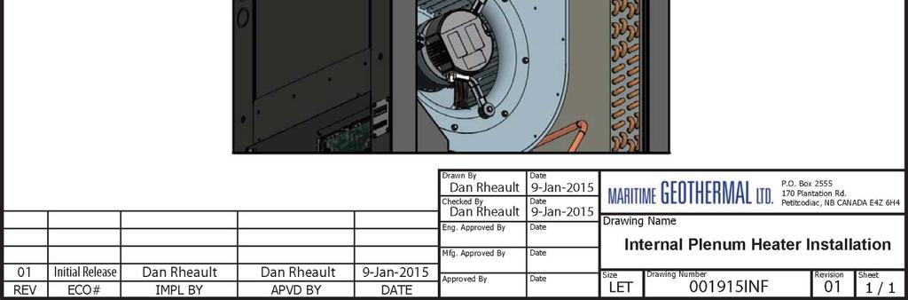
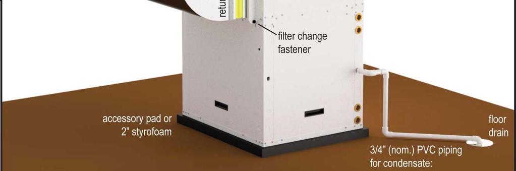
10 Unpacking the Unit When the heat pump reaches its destination it should be unpacked to determine if any damage has occurred during shipment. Any visible damage should be noted on the carrier's freight bill and a suitable claim filed at once. Unit Placement Ducted or forced air heat pumps should be centrally located in the home with respect to the conditioned space. This provides the best in economy and comfort and usually can be accomplished in harmony with the design of the home. A heating system cannot be expected to produce an even warmth throughout the household when it is located at one end of the structure and the heated or cooled air is transmitted with uninsulated metal ductwork. If possible the front access panel and side access panel opposite the air return should remain clear of obstruction for a distance of 2 ft (0.7 m) to facilitate servicing and general maintenance. No access is required on the back side. Ensure the unit is level to eliminate any possible condensate draining issues. The heat pump comes equipped with an air filter rack which can be installed with the removable end (where the filter is inserted) on either side to facilitate changing the filter. Be careful not to run piping in front of the filter rack access cover, since access is required in order to change the air filter. Raising the indoor unit off the floor a few inches is generally a good practice since this will prevent rusting of the bottom panel of the unit and deaden vibrations. An anti-vibration pad, available as an accessory, or a piece of 2 styrofoam should be placed under the unit. Air Outlet Orientation The unit has a field configurable blower position, resulting in top or side air discharge. Its default location from the factory is in the top of the unit, providing a ninety in the airflow. It can easily be placed in the side of the unit for straight through airflow. Note that if this is done, plenum heater will need to be placed in ductwork outside unit. To switch the location of the fan outlet: 1. Turn the power of to the unit. 2. Remove the screw that holds the side access panel in place and remove the access panel by pulling up on the handle and then outward from the bottom. 3. Disconnect the two wire harnesses and ground wire from the fan motor. 4. Repeat step 2 for the access panel with the fan mounted in it. Set the assembly on the floor. 5. Disconnect the plenum heater extension from the fan housing and from the access panel. 6. Mount the fan housing directly to the access panel. 7. Install the fan/panel in the new location and secure with the screw. 8. Reconnect both harnesses and ground wire. 9. Install the remaining access panel and secure with the remaining screw. Top Discharge (Internal Plenum Heater) Side Discharge (External Plenum Heater) Air Return Orientation The heat pump can be ordered as left or right return from the factory. This must be specified at time of order as the physical construction of the two configurations is different. Refer to the Dimensions section toward the end of this manual for physical dimensions of the units MAN-01 Page 10

11 Page MAN-01
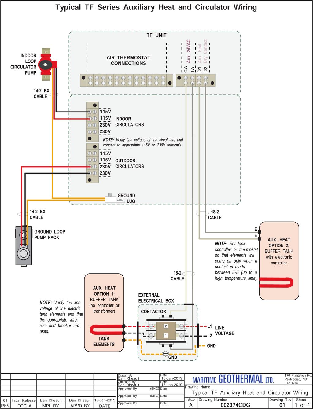
12 Wiring Power Supply Connections Power supply for the heat pump from the breaker panel is supplied to the unit via concentric / knockouts. There are also several 7/8 knockouts and a 1/2 opening with plastic grommet (grommet hole is 3/8 ) for connections to the air thermostat, optional aquastat, and indoor / outdoor loop circulators. A schematic diagram (SCH) and electrical box layout diagram (ELB) can be found on the electrical box cover of the unit as well as in the Model Specific Information section of this manual. The Electrical Tables in the Model Specific Information section contain information about the wire and breaker size. IMPORTANT NOTE: A properly qualified electrician should be retained for all connections to the heat pump and associated controls. The connections to the unit MUST CONFORM TO LOCAL CODES. TABLE 4 - Power Supply Connections Line Description Voltages L1 Line 1 All L2 Line 2 All L3 Line 3 3-phase only N Neutral 208/ *, * (optional) , (required) GND Ground All (connect to ground lug) * Only required if connecting 115VAC circulators. Auxiliary Plenum Heater: Power Supply Connections Auxiliary air heat will usually be provided by an electric duct heater (plenum heater). These are available as accessories in 5, 7, 10, 15, and 20 kw sizes, and are installed as previously noted in this manual. The plenum heater will have its own breaker and power supply wire. The Electrical Tables in the Model Specific Information section contain information about the size of wire for the connections, as well as the recommended breaker size. Auxiliary Plenum Heater: Signal Connections There are two dry contacts to control the 2 stages of the plenum heater. These dry contacts can also be used to control other types of auxiliary air heat. Note that dry contacts are intended to activate equipment that has its own 24VAC transformer; if equipment does not have its own transformer, one will need to be installed in an external electrical box. Connect the terminals on the heat pump terminal strip to the matching terminals on the plenum heater s control board using an 18-3 cable. TABLE 5 - Plenum Heater Signal Connections Signal Description CP Common 1 Dry contact for auxiliary heat stage 1 2 Dry contact for auxiliary heat stage 2 Use a 3-conductor 18ga cable. Indoor Loop Circulator Pump Wiring There are provisions for connecting the indoor circulator pump (between the heat pump and buffer tank) so that it will be turned on whenever the compressor operates, or when sampling water temperature. Connect the circulator pump to the appropriate two terminals (115V or 230V) of the terminal strip marked Indoor Circulators, as per the voltage of the circulator pump. Ground wires should be connected to the ground lug in the electrical box. Ensure that the total current draw does not exceed the value indicated on the label in the heat pump electrical box. For 460VAC models, only 277VAC circulators may be powered directly from the heat pump. If other voltage circulators are used, they must be powered using an external contactor actuated by the ICR terminal on the left side of the control board and the C (24V ground) terminal. Outdoor Loop Pump Module Wiring (Ground Loop Only) There are provisions for connecting the ground loop circulator pump module so that the pumps will be turned on whenever the compressor operates. Connect the circulator pump module to the appropriate two terminals (115V or 230V) of the terminal strip marked Outdoor Circulators in the heat pump, as per the voltage of the circulator pump module. Ground wires should be connected to the ground lug in the electrical box. Ensure that the total current draw does not exceed the value indicated on the label in the heat pump electrical box. For 460VAC models, only 277VAC circulators may be powered directly from the heat pump. If other voltage circulators are used, they must be powered using an external contactor actuated by the STAGE 1 terminal on the bottom side of the control board and the C (24V ground) terminal. TABLE 6 - Indoor & Outdoor Circulator Connections Terminal Description 115V 115V Connection for 115V circulator 230V 230V Connection for 230V circulator Use a 2-conductor 14ga cable. Control Transformer The rest of the low voltage controls, including the control board, are powered by a 100VA class II transformer. 208/ and models have a resettable breaker on the secondary side for circuit protection. Should the breaker trip, locate and correct the problem and then reset the breaker by pressing in on it. All other voltage models have primary and secondary fuses for circuit protection. IMPORTANT NOTE: For 208/230VAC-1-60 units, if connecting to 208VAC power supply move the red wire connected to the 240 terminal of the transformer to the 208 terminal of the transformer MAN-01 Page 12
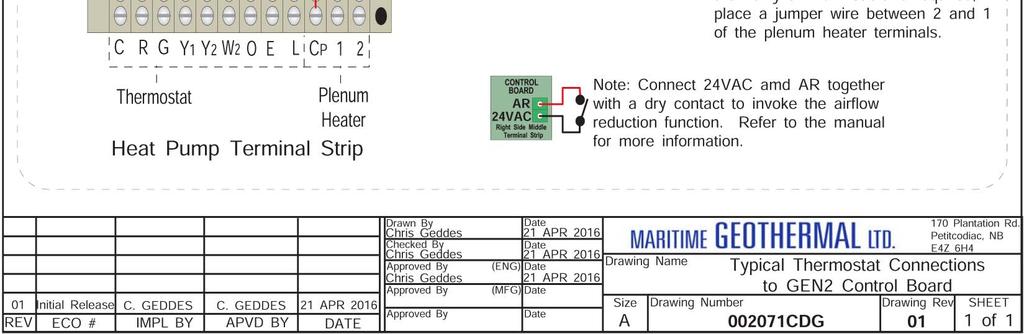
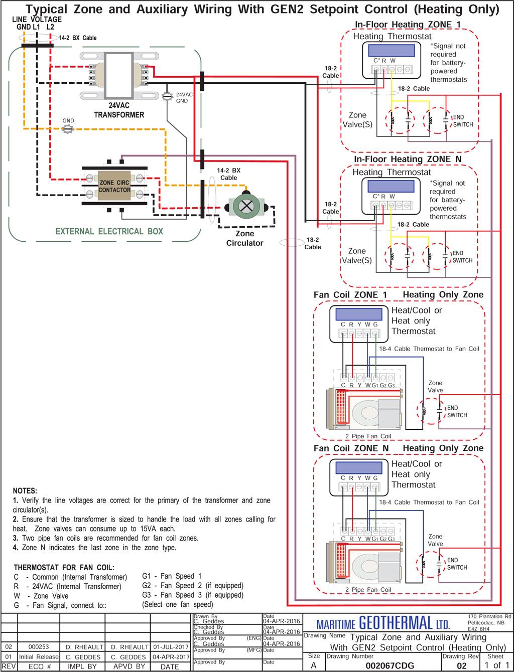
13 Open/Closed Loop Wiring The heat pump is provided configured for closed loop operation. For open loop operation, it is necessary to remove the jumper plug from the wiring harness found behind the pipe post and plug in the water valve harness. This will select the proper low pressure control. See the Water Valve section in the Open Loop Installations chapter and CDG for details. WARNING: Connecting an open loop water valve without a harness provided by Maritime Geothermal could lead to frozen and ruptured heat exchanger, voiding the warranty. Domestic Hot Water (Desuperheater) The desuperheater function for domestic hot water heating is pre-wired and no field connections are necessary. After the desuperheater is filled with water and purged of air, activate the built-in DHW circulator by connecting the brown wire with the blue insulated terminal to L1 of the compressor contactor as shown on the wiring diagram in the Model Specific Information section. Ensure the power is off when connecting the wire. Also, turn on the DHW ON/OFF switch. Ducted Air Thermostat Connections A three-stage heating and two stage cooling heat pump configurable thermostat is required. The stages are S1 = stage 1 compressor, S2 = stage 2 compressor and S3 = electric auxiliary (in heating mode only). One can be ordered with the unit, or other heat pump thermostats with the same number of stages can be used. The air thermostat connections are located on a terminal strip in the heat pump electrical box. Refer to diagram on a following page for connections between the thermostat and the heat pump. The air flow can be further reduced by an adjustable amount between 5 and 20% (value set in PC App) by making a dry contact across 24VAC and AR on the right side middle terminal strip of the control board. This can be used for applications that have multiple air zones. Care should be taken to ensure that the unit does not trip a safety control in heating or cooling mode if the AR reduction is used in conjunction with lower air flow settings. TABLE 7 - Air Thermostat Connections Signal Description C 24VAC common (ground) R 24VAC hot G Fan low speed (for air recirculation) Y1 Heat pump stage 1 Y2 Heat pump stage 2 W2 Heating stage 3 (plenum heater) O Cooling mode (reversing valve) E Emergency heat (plenum heater) L Fault (24VAC when fault condition) AR Airflow reduction: connect AR to 24VAC with a dry contact to reduce the airflow for zoning. Connections located on right side of control 24VAC board. Hydronic Backup Wiring When using Setpoint Control, there are two methods for activating a hydronic backup/auxiliary heating device. First, a 24VAC control signal on terminal 1A (with CA as ground/common) is available to power the coil of an external contactor in order to operate hydronic auxiliary heat. Choose this method if using a heating device that doesn t have its own electronic controller or control transformer, e.g. a bare heating element in the buffer tank. This signal can provide a maximum of 500mA at 24VAC. Second, a dry contact on terminals D1 and D2 is available, to actuate a heating device that has its own control transformer. In general, these types of devices will have their own electronic temperature controller. Therefore, it will be necessary to set the on-board temperature control on the external heating device only so that it is a high limit, and it will be activated by the heat pump s controller when required for stage 3 heat. This method should be used for the Thermo2000 EcoUltra tank that is available from Maritime Geothermal as an accessory. If not using Setpoint Control, backup device may use its own controls, provided they are accurate (i.e. devices with a digital controller). Setpoint should be set lower than stage 2. Or stage 2 of the aquastat with a delay timer may be used. TABLE 8 - Hydronic Auxiliary Connections Signal CA 1A D1 D2 Aquastat Connections (Optional) Most installations will use the internal Setpoint Control routine to control buffer tank temperature, so no aquastat is required. However, an aquastat or aquastats can be used if required, for example if heating two loops with different setpoint temperatures. This is called Signals or Hardwired Control. The wiring connections are at the top right of the control board, on the screw terminal connector section marked AQ- UASTAT. This is shown on the wiring (SCH) diagram in the Model Specific Information section. The external device needs to send the 24VAC signal from RA back to the Y1A and Y2A terminals to call for the two stages of hydronic heating. C is the common or ground terminal for powering the external device. TABLE 9 - Aquastat (Signals Control) Connections Signal C R Y1A Y2A Description 24VAC common (ground) 24VAC hot Compressor ON (Part Load) Compressor bump up to Stage 2 (Full Load) Other Connections Description 24VAC common (ground) Hydronic Auxiliary (hot) Hydronic Auxiliary dry contacts In most installations, accessories that are not already described will not be required. Other available accessories or external connections include: External buffer tank temperature sensor, replacing the internal water OUT line temperature sensor for use with the control board s Setpoint Control routine. This is called HTS/ CTS Setpoint Control, described later. Compressor current sensor. BACnet, for external control of air heating/cooling and water heating demand by the building control system. See the wiring (SCH) diagrams in the Model Specific Information section or on the electrical box cover for these connections. Page MAN-01
14 002362MAN-01 Page 14
15 Page MAN-01
16 002362MAN-01 Page 16

17 Page MAN-01
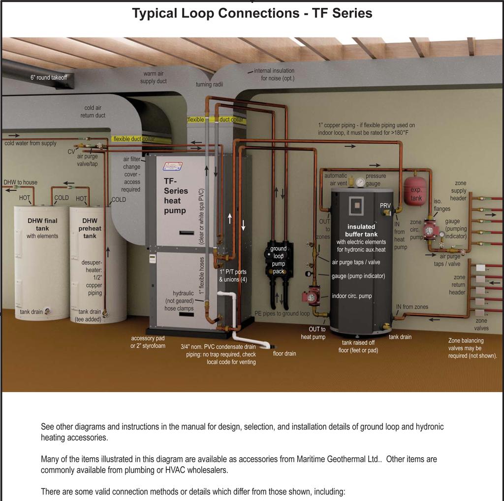
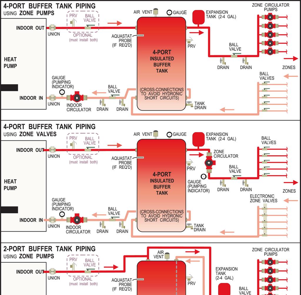
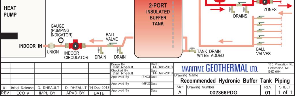
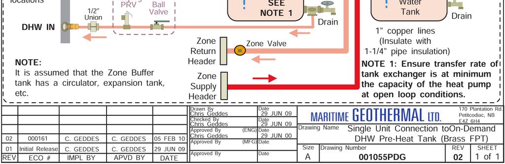
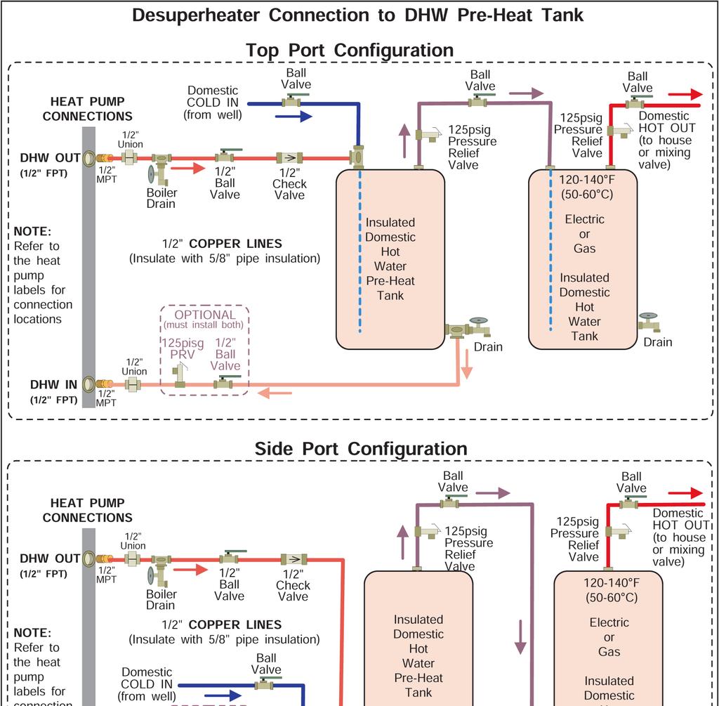
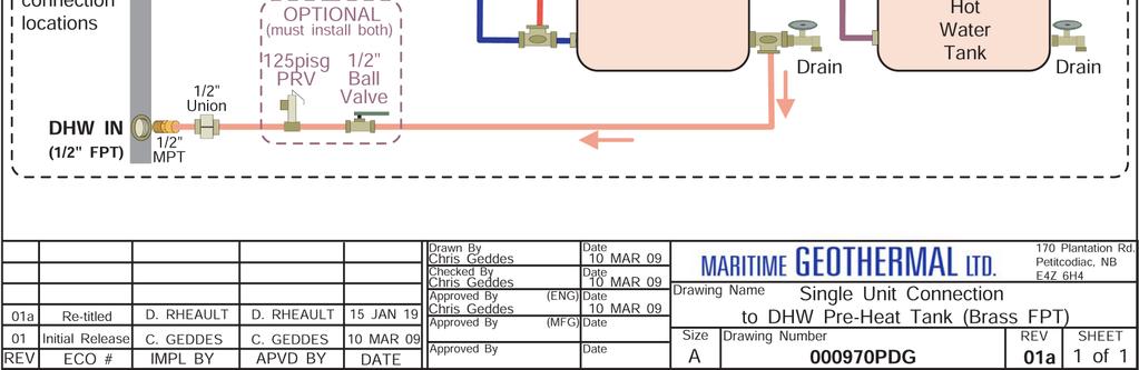
18 Piping Indoor Loop The connections for the Indoor Loop circuit are 1 brass female NPT. They are labelled as INDOOR IN and INDOOR OUT. Use of a buffer tank is mandatory, in order to maintain control over water temperature, and to avoid safety control tripping problems associated with mismatching of heat pump output and zone absorption. Typical systems using 4 port and 2 port buffer tanks are shown in following drawing PDG. This diagram shows all of the recommended components as well as where they should be placed, whether using zone valves or zone pumps. NOTE: It is recommended that the water lines between the heat pump and the buffer tank be copper or other high temperature piping. NOTE: Care should be taken when routing the water lines to ensure that adequate access to the heat pump is maintained so as to not compromise ease of serviceability. The minimum buffer tank size should follow the rule of 8 US gallons per ton of heat pump capacity. The following table shows the minimum buffer tank size for each heat pump along with the recommended size. The recommended size will minimize the number of starts per hour and provide longer runtimes for improved efficiency. TABLE 10 - Buffer Tank Size Heat Pump Size Minimum Size gallons (Litres) Recommended Size gallons (Litres) (90) 50 (190) (120) 70 (265) (150) 70 (265) (180) 70 (265) (200) 70 (265) If a tank size is not available, use the next size larger tank. Outdoor Loop The connections for the Outdoor Loop circuit are 1 brass female NPT. They are labelled as OUTDOOR IN and OUTDOOR OUT. See the following chapters for details on ground loop and open loop installations. Condensate Drain The unit comes equipped with one 3/4 female PVC socket drain connection. This drain allows the condensate which forms during the air conditioning cycle to be removed from the unit. The drain should be connected and vented as per local codes. During high humidity weather, there could be as much as 25 gallons of water formed per day. The condensate drain is internally trapped and does not require an external trap. An external condensate pump may be installed if there is not sufficient slope to drain condensate under gravity to its destination. To avoid overflow of the condensate pan, the drain line and trap should be inspected periodically to ensure they are not plugged with accumulated debris. There is an alarm for condensate overflow, which will disable unit operation. Domestic Hot Water (Desuperheater) Connections The port connections for the DHW circuit are 1/2 brass FPT fittings. They are marked as DHW IN and DHW OUT. A typical piping diagram for a pre-heat tank configuration can be found in drawing PDG at the end of this section. Be sure to note the position of the check valve and the direction of water flow. Other configurations are possible, and there may be multiple units piped together in larger buildings. WARNING: USE ONLY COPPER LINES TO CONNECT THE DESUPERHEATER. TEM- PERATURES COULD REACH 200F SHOULD THE DHW CUTOUT SWITCH FAIL, POTEN- TIALLY MELTING & RUPTURING PLASTIC PIPING. Ensure the tank is filled with water and under pressure before activating the built-in DHW circulator as described below. First, slightly loosen the boiler drain on the DHW Out pipe to allow air to escape from the system. This step will make certain that the domestic hot water circulator in the unit is flooded with water when it is started. CAUTION: the domestic hot water pump is water lubricated; damage will occur to the pump if it is run dry for even a short period of time. Activate the built-in DHW circulator by connecting the brown wire with the blue insulated terminal to L1 of the compressor contactor. Ensure the power is off when connecting the wire. Once connected the DHW switch on the front of the unit may be used to enable/disable the domestic hot water circulator. The DHW loop may have to be purged of air several times before good circulation is obtained. A temperature difference between the DHW In and DHW Out can be felt by hand when the circulator pump is operating properly. For the pre-heat tank setup, the final tank should be set to 140 F (60 C), which is required by most codes. The preheat tank does not require electric elements. This setup takes full advantage of the desuperheater as it is the sole heat provider to the pre-heat tank. The desuperheater remains active during the compressor runtime until the pre-heat tank has been completely heated by the desuperheater alone. This setup is more energy efficient than a single tank setup, and eliminates the possibility of reverse heating of the refrigerant gas in cooling mode. CAUTION: If two (2) shut-off valves are located on the domestic hot water ines as shown in the diagram, a pressure relief valve must be installed to prevent possible damage to the domestic hot water circulator pump should both valves be closed MAN-01 Page 18
19 Page MAN-01
20 002362MAN-01 Page 20
21 Page MAN-01
22 002362MAN-01 Page 22
23 Page MAN-01
24 002362MAN-01 Page 24


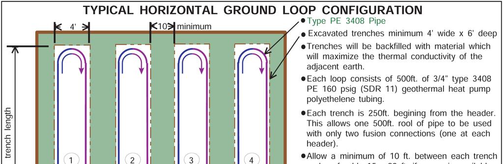
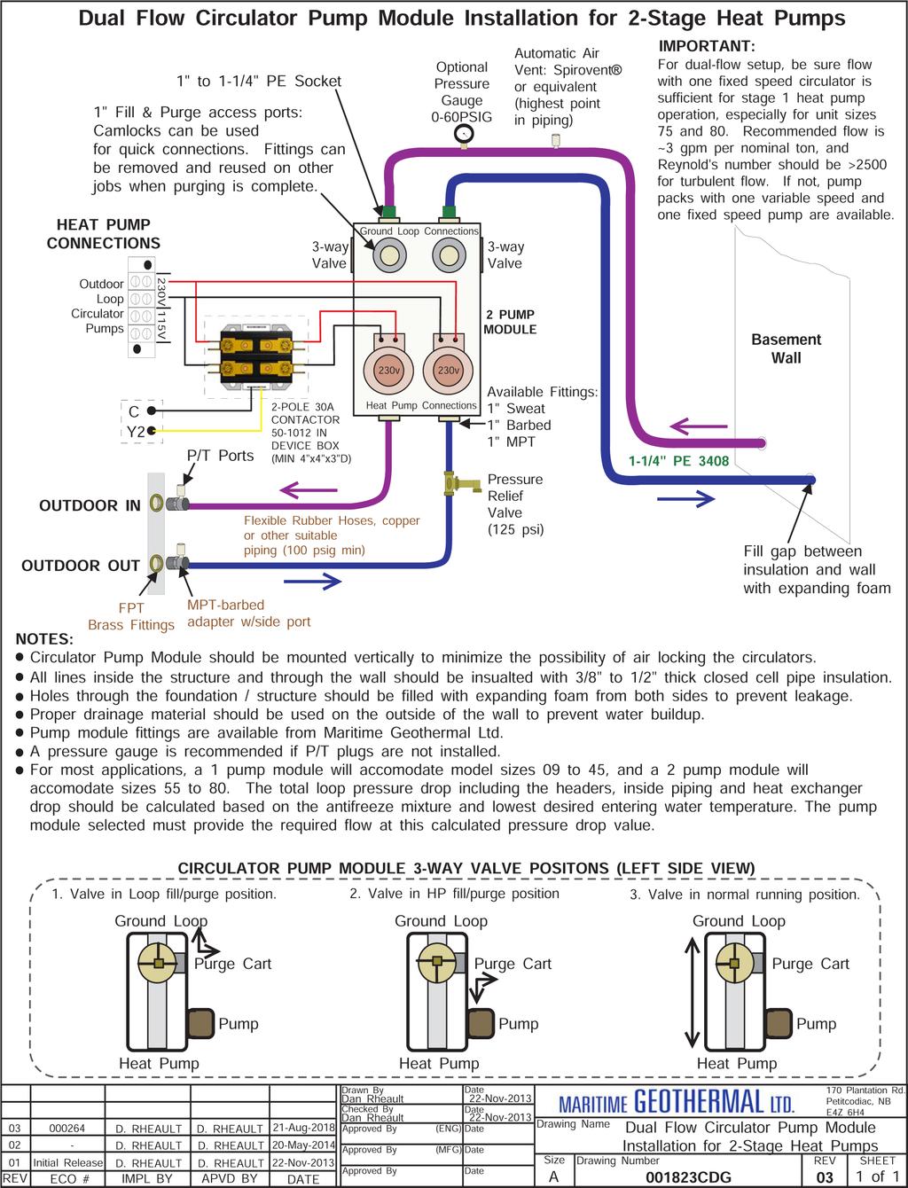
25 Ground Loop Installations Refer to diagrams INF & INF at the end of this section for typical ground loop configurations. They are for reference only, and should not be used to replace formal training and computerized loop design. Once the ground loop has been pressure tested and the header pipes have been connected to the circulator pump module, the heat pump can be connected to the circulator pump module. The port connections for the Outdoor Loop are 1 brass FPT fittings. They are marked as OUTDOOR IN and OUTDOOR OUT. Circulator Pump Module Maritime Geothermal Ltd. offers compact pump modules with built in three way valves to facilitate filling and purging the ground loop. Refer to drawing CDG at the end of this section. Alternatively, Grundfoss Model UPS or Taco Model 0011 pumps or other brands with similar pumping capability may be used. The single pump module will typically handle systems up to 3 tons (model sizes 25, 35, and 45); the two pump module will typically handle 4 to 6 ton systems (model sizes 55, 65, 75, 80). This is based on a typical parallel system with one circuit per ton. Maritime Geothermal recommends calculating the total pressure drop of the ground loop (including headers, indoor piping and heat pump exchanger drop) based on the antifreeze type and concentration at the desired minimum loop temperature. A pump module that can deliver the flow required for the unit at the calculated total pressure drop should be selected. Refer to the Model Specific Information section for unit flow requirements. Loop pressure drops can be calculated using software such as those mentioned in the Horizontal Ground loops section, or can be calculated in a spreadsheet using the pipe manufacturer s pressure drop tables for pipe diameter and fittings. The circulator pump module must be connected to the heat pump Outdoor Loop ports with a lineset suitable for the flow required with minimum pressure drop. 1 rubber or plastic lines should be used. The installation of P/T plugs/ports (pressure / temperature, pronounced Pete s plugs ) is recommended on both the entering and leaving lines at the heat pump. This will allow the installer or homeowner to check water flow through the loop by measuring the pressure difference through the heat exchanger and comparing it to that listed in the Model Specific Information section. P/T ports, adapters, and gauge adapters and are available as accessories from Maritime Geothermal Ltd.. Flushing & Purging Once the groundloop has been installed and all connections are completed between the heat pump, circulator pump module and ground loop, the entire ground loop system should be pressure tested with air to 100 PSIG to make sure there are no leaks on any of the inside fittings. Soap all joints and observe that the pressure remains constant for 1 hour. When satisfied that all connections are leak free, release the air pressure and connect a purge cart (see Figure) to the flushing access ports at the pump module (refer to drawing CDG). A temporary flushing system can alternately be constructed using a 45 gal. barrel and a pump with sufficient volume and head capability to circulate fluid at a velocity of at least 2 ft./min. through all parts of the loop. Adjust the circulator pump module valves to connect the purge cart to the ground loop. Begin pumping water through the ground loop, ensuring that the intake of the pump stays submerged at all times by continuously adding water. Water flowing back from the return line should be directed below the water level in the barrel or flush tank to prevent air being mixed with the outgoing water. Figure 1: Ground Loop Accessories & Tools 2-pump module Barbed Adapters PE Adapters Purge Cart P/T port Gauge adapter for P/T port P/T adapters for heat pump (1 NPT to barb) Page MAN-01
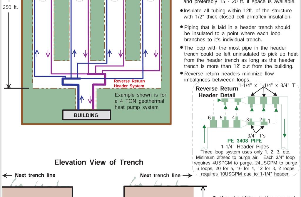
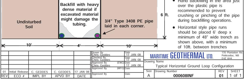
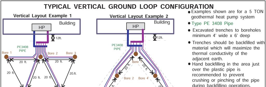
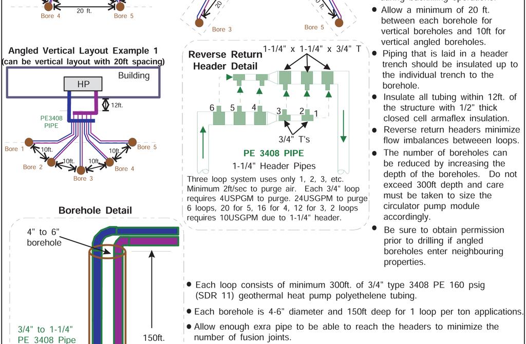
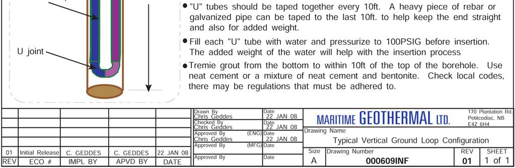
26 Once the lines have been filled and no more air bubbles are appearing in the line, adjust the circulator pump module valves to circulate water through the heat pump using the same technique as described above. When all air is removed reverse the flow of water through the lines by interchanging the flush cart lines and purge again. You will be able to visibly tell when all air is removed. Adding Antifreeze Solution In most mid and northern areas of the US and in all of Canada it is necessary to condition the loop fluid by the addition of some type of antifreeze solution so that it will not freeze during operation in the winter months. This antifreeze is required because the loop fluid will normally reach a low entering temperature of 28 F to 32 F (-2 C to 0 C) and refrigerant temperatures inside the heat pump s heat exchanger may be as low as 20 F (11 C) cooler. See table for details of freeze protection provided by different concentrations. TABLE 11 - Antifreeze Percentages BY VOLUME Protection to: 10 F 15 F 20 F 25 F Methanol 25% 21% 16% 10% Propylene Glycol 38% 30% 22% 15% BY WEIGHT Protection to: 10 F 15 F 20 F 25 F Methanol 16.8% 13.6% 10% 6.3% Propylene Glycol 30% 23.5% 18.3% 12.9% WARNING: Add enough antifreeze to allow for a temperature 20 F (11 C) lower than the expected lowest loop fluid temperature entering the heat pump. Insufficient antifreeze concentration could cause the heat exchanger to freeze and rupture, voiding the warranty. Although many different antifreeze solutions have been employed in geothermal systems, the alcohols such as methanol or ethanol have the most desirable characteristics for groundloop applications. The overall heat transfer characteristics of these fluids remain high although care must be taken when handling pure alcohols since they are extremely flammable. Once mixed in a typical 25% by volume ratio with water the solution is not flammable. In situations where alcohols are not allowed as a loop fluid due to local regulations then propylene glycol is a non-toxic alternative which can be substituted. Propylene glycol should only be used in cases where alcohols are not permitted since the heat transfer characteristics are less desirable and it becomes more viscous at low temperatures, increasing pumping power. The volume of fluid that your loop system holds can be closely estimated by totaling the number of ft. of each size pipe in the system and referencing table for approximate volume per 100 ft. When the volume of the loop has been calculated and the appropriate amount of antifreeze is ready for addition by referencing table; drain the equivalent amount of water from the flush cart or mixing barrel and replace it with the antifreeze. TABLE 12 - Volume of fluid per 100 ft. of pipe Volume /100ft. Type of Pipe Diameter I.gal gal L Copper / / Rubber Hose Polyethylene 3/4 IPS SDR IPS SDR /4 IPS SDR /2 IPS SDR IPS SDR Other Item Volumes Heat Exchanger Average Purge Cart Tank See cart manual TBD When using alcohols, be sure to inject below the water line to reduce initial volatility of the pure antifreeze. If the loop is large it may be necessary to refill the tank with antifreeze several times to get all the antifreeze into the loop. Pump the loop for 5 to 10 minutes longer to ensure the remaining fluid has been well mixed. Initial Pressurization At this point open all valves in the flow circuit and slowly close off the supply and return flush cart valves in a manner that leaves about psig on the system. If an air bladder expansion tank is used it should be charged to the above pressure before actual water pressure is put on the system. Systems without an expansion tank will experience greater fluctuations in pressure between the heating and cooling seasons, causing pressure gauges to have different values as the loop temperature changes. This fluctuation is normal since expansion and contraction of the loop fluid must be handled by the elasticity of the plastic loop. Pressurize the loop to a static pressure of 45 psig. when installing a system in the fall going into the heating season. Pressurize the loop to a static pressure of 25 psig. when installing a system in the spring or summer going into the cooling season. After operating the heat pump for a period of time, any residual air in the system should be bled off and the static pressure should be verified and adjusted if necessary. Add additional water / antifreeze mix with the purge cart to bring the pressure back to the original setting if required. Pipe Insulation All ground loop piping inside the structure (between the structure entry point and the heat pump) should be insulated with 3/8 thick closed cell pipe insulation to prevent condensation and dripping onto floors or walls MAN-01 Page 26
27 Page MAN-01
28 002362MAN-01 Page 28

29 Page MAN-01
30 002362MAN-01 Page 30

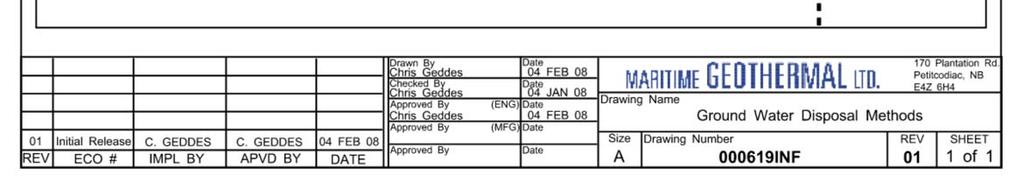
31 Open Loop Installations Well Water Temperature The temperature of the well water should be a minimum of 41 F (5 C), and should normally be 45+ F (7 C+). In general, groundwater temperatures across the Canadian prairie provinces and Northern Ontario may be close to the 41 F minimum, while in other parts of southern Canada it will probably be F, although local exceptions will exist. In more southern locations, it will be warmer. The groundwater temperature should be verified as the first step in a proposed open loop installation. Well Water Flow The water source is normally a drilled water well with submersible pump that is the same well which supplies domestic water needs. It must be able to supply the required water flow as listed under the Total Flow column in the table. TABLE 13 - Required Flow Heat Pump Model Size Heat Pump Flow* gpm (L/s) Domestic Water Usage gpm (L/s) Total Flow gpm (L/s) (0.50) 4 (0.25) 12 (0.76) (0.63) 4 (0.25) 14 (0.88) (0.76) 4 (0.25) 16 (1.01) (0.88) 4 (0.25) 18 (1.14) (1.01) 4 (0.25) 20 (1.26) (1.07) 4 (0.25) 21 (1.32) * These are minimum water requirements based on an entering water temperature of 45 F. For groundwater temperatures of 50 F or greater, these flows can be reduced by 25% if required. Rather than being estimated by a well driller, the flow from a proposed source well should be measured by performing an extended flow test to be sure it is capable of supplying the required flow over an extended period of time. This is done by flowing the well at the highest possible rate, noting the static water level in the well, and monitoring the pumping fluid level until stable. Unless the fluid level is very high, fluid level monitoring will require a device called a water level sounder. The flow rate can then be measured either by a cumulative gallon meter, a flowmeter, or by timing the filling of a bucket of known size. The test data can be recorded as follows: It is best to flow the well for as long as possible (e.g. 12 hours) at the flow rate required by the proposed heat pump size. However, if the test is performed before a larger submersible pump is installed, it may be assumed that any unused water level drop during the test (that is, any distance remaining be- tween the pumping fluid level and the pump intake) would contribute linearly to the flow rate should a larger pump be installed. In the above example, it was recorded that the flow rate stabilized at 6 gpm, while the water level dropped from 20 to 29 feet (9 feet). If the intake of a larger pump could be placed so that a further pumping fluid level drop of 9 feet could be achieved (total 18 feet), it can be assumed that the flow would double to 12 gpm. Of course, this should be verified with a second test once the larger pump is actually installed. Well Water Quality The well water should be tested to be sure it meets minimum standards. Although the threat of poor water quality to open loop installations is often exaggerated, poor water quality can lead to rapid heat exchanger failure or frequent servicing. First, the well should not produce any sand. Sand will physically erode heat exchanger surfaces, and quickly clog return (injection) wells. Solids or TDS should be less than 1 ppm (1 mg/l) if a return well is used. To avoid scale formation on the inside of the heat pump s outdoor loop coil, total hardness should be less than 350 ppm / 350 mg/l. In practice, scaling is very rarely a problem at northern groundwater temperatures of 50 F or less because scale does not generally form at low well water temperatures (unlike, for example, in a domestic hot water tank). In more southern climates, the hardness guideline will be a more important consideration. Should scale form, heat pump performance will gradually deteriorate, and will require periodic flushing with a calcium/lime removing solution (see General Maintenance section). If the need for periodic flushing is anticipated, the optional Cupro-Nickel (CuNi) coil and piping should be ordered. Corrosive (salty) water can cause failure of the inner tube of the heat exchanger, leading to loss of refrigerant and water entering the refrigeration circuit, which ruins the heat pump. If chlorides exceed 20 ppm (20 mg/l), the optional CuNi coil and piping should be ordered. If chlorides exceed 150 ppm (150 mg/l), or significant Ammonia (>0.5 ppm) or H 2 S (>0.2 ppm) is present, the use of an open loop system should be reconsidered. Water Discharge Methods Water disposal methods vary from area to area. However, some consideration should be made to prevent the cooled discharge water from immediately coming in contact with the supply source. Attempting to return the water to the source well will eventually cool the water so much that the heat pump will shut off on its low pressure safety control. Acceptable methods for disposing of the waste water are listed below. The waste water is clean; the heat pump has no effect other than reducing the temperature of the water. Refer to drawing INF for typical disposal method diagrams. Second well (return well) Percolation (Drain, ditch, leaching field) Pond, river or stream ENSURE SELECTED METHOD CONFORMS TO LOCAL REGULATIONS. A return well should be a minimum of 80 ft. from the supply well for residential applications. The water returned to the well Page MAN-01
 will not necessarily be pumped into the same aquifer, depending on underground conditions.")


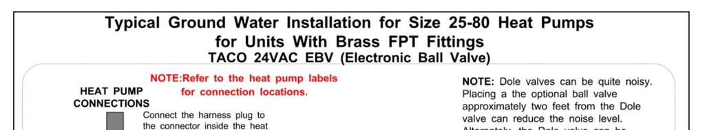
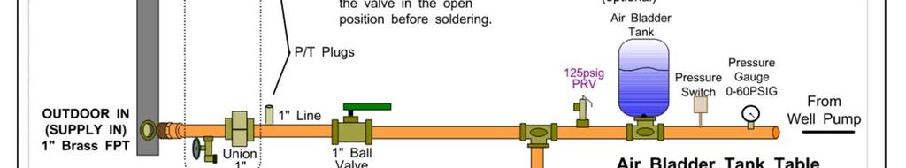
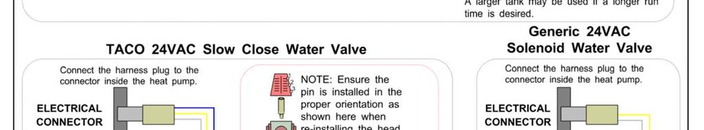
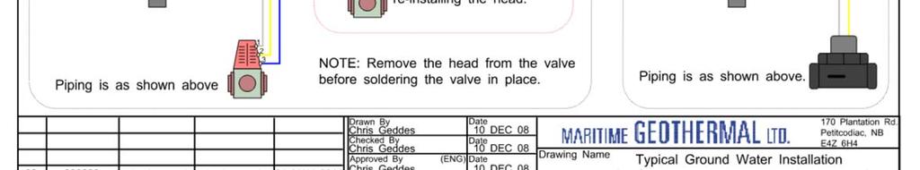
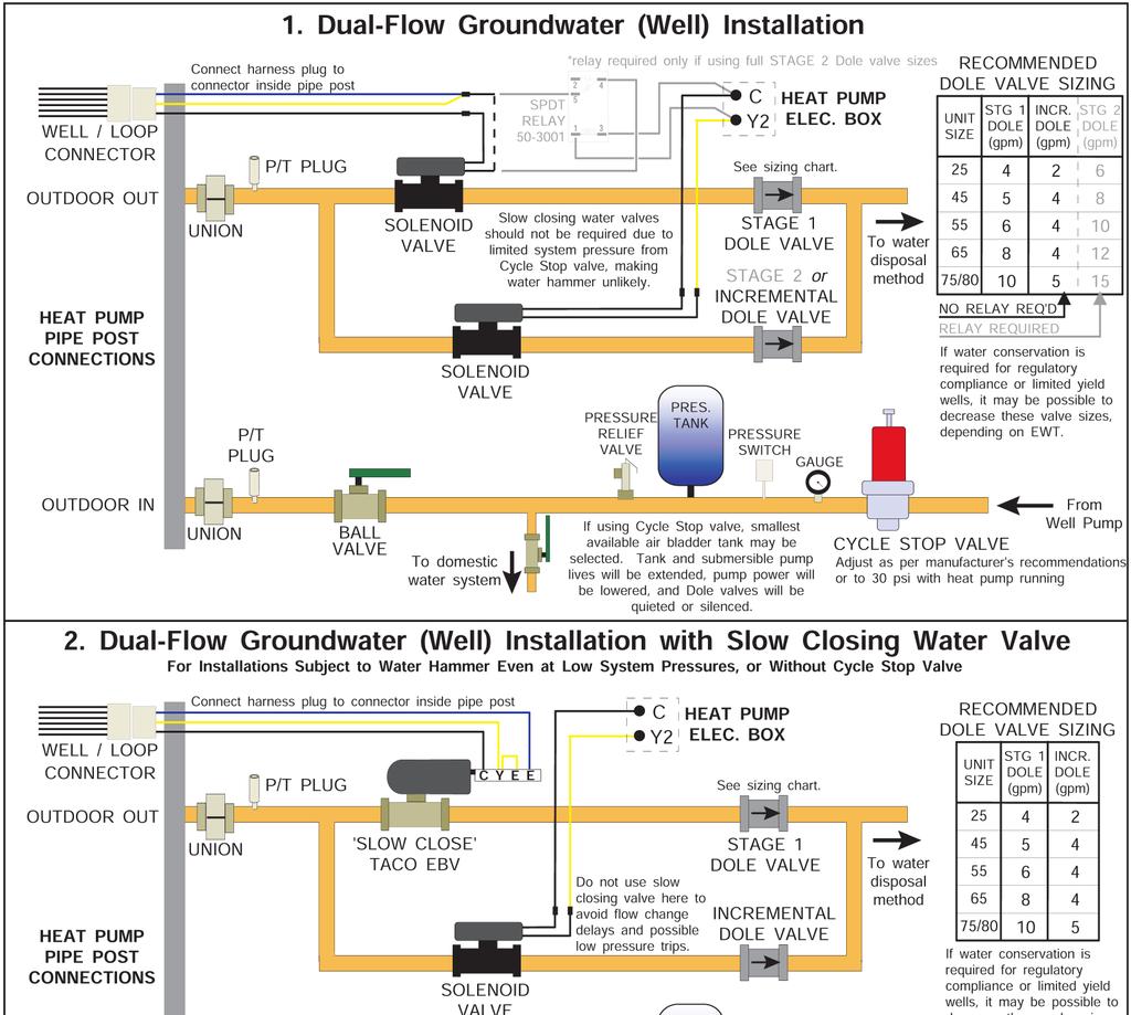
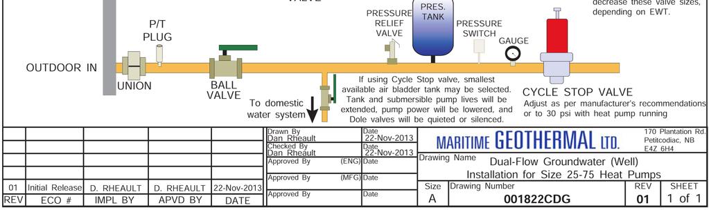
32 Figure 2: Open Loop Accessories & Tools Water Level Sounder Taco EBV Dole Valve Rainbird Solenoid Valve P/T port Cumulative Gallon Meter Gauge adapter for P/T port P/T adapters for heat pump (1 NPT to barb) will not necessarily be pumped into the same aquifer, depending on underground conditions. The return well must be able to supply at least the same quantity of water as the amount you wish to inject into it, preferably much more, since injection capacity will tend to decrease over time due to clogging. It may be necessary to place a pressure-tight cap on the well to keep the return water from flowing out the top of the well. This cap is commonly required since a certain amount of pressure may be needed to force the return water back down the well in cases of limited injectivity. Water discharged by percolation will generally soak into the ground within a distance of 50 to 100 ft. If suitable care is taken to ensure that the drain pipe runs downhill and the end of the pipe is protected by a bale of hay or spruce bows, the end of the pipe will not freeze as the pipe will empty out when the heat pump shuts off and the water valve closes. A screen should be installed on the end of large discharge pipes, to prevent animals from building nests inside during extended off periods and causing a backflooding risk for open water drains. When snow comes it will usually cover the entire process much like a small spring. It is recommended that the pipe be below the frost line when possible for maximum freeze protection. When discharging into a river or stream, or above the surface of a pond, the same guidelines should be followed as described in the paragraph above for the percolation method. When discharging the waste water below the surface of a pond or lake, the discharge pipe should be placed below the frost line to prevent the pipe from freezing. As opposed to the percolation method, water will remain in the end of the pipe. It is recommended that the surface of the pond be lower than the installation location of the heat pump. This reduces the back pressure generated by the weight of the water in the pond. Water Valve Water flow through the heat pump is turned on and off by a water valve, which is controlled by a 24VAC signal from the heat pump. It should be installed on the OUT pipe of the heat pump, so that the heat exchanger remains full of water at all times. There are two types of water valves available from Maritime Geothermal. Most installations use a Taco slow closing motorized ball valve (EBV). This takes ~5 seconds to close, and avoids the water hammer which can occur with faster acting valves. There is also a more economical fasting acting Rainbird solenoid valve available, for applications where water hammer is not expected. Both come with a wiring harness, which plugs into a connector behind the pipe post of the heat pump. This both allows the heat pump to properly control the valve, turning the water flow on and off with the compressor, and also tells the heat pump to select the higher low pressure safety control for open loop (since there is no antifreeze present). Water Flow Control A flow restricting ( Dole ) valve is highly recommended, installed downstream of the water valve. This is a passive (nonelectrical) device which automatically varies the size of its rubber orifice in order to restrict flow to its stamped gpm value, regardless of water pressure. This is important in order to provide some backpressure to the water system, which could otherwise be too low for the comfort of people taking showers or otherwise using the domestic water system. It also prevents excessively low refrigerant discharge pressure when in cooling mode. Dole valves are available as an accessory MAN-01 Page 32
33 Dole valves can emit a whistling sound if the pressure drop through them is high. Therefore, they should be placed where the noise will not cause a nuisance, e.g. outside the basement wall or perhaps in a well insulated box. Submersible Pump Selection Of course, the submersible pump must be large enough to supply the flow required by the heat pump. This is usually not a problem, pumps often being oversized by default. However, if a conventional fixed speed pump is too large, its fixed capacity will exceed that of the Dole valve at reasonable pressure switch settings (<80 psi). This will cause the submersible pump to cycle on and off continuously while the heat pump is running, causing excessive wear to the submersible pump. The installation of a large air bladder tank will cause the cycles to have a longer duration, but will not solve the problem. To avoid this problem, the fixed speed pump should be sized according to its head vs. flow curve. The required head should be calculated using height between the pumping fluid level in the well and the elevation of the heat pump, pipe pressure drop at nominal flow rate, desired system water pressure, and any back pressure from return well. Then a pump can be selected that delivers the nominal flow for the chosen heat pump size at that head. In case this calculation is not exact, a variety of Dole valves can be carried by the installer, and a larger Dole valve installed if submersible pump cycling is observed. An alternate approach would be to install a variable speed submersible pump, which varies its speed to maintain a constant water system pressure. Or use a mechanical cycle stop valve, which is installed upstream of the air bladder / pressure tank and varies its orifice to put backpressure on the pump during periods of low flow in order to keep it from cycling off. Stage 1 vs. 2 on Open Loop In an open loop installation, the submersible water pump draws significant power compared to the heat pump, especially for smaller heat pump sizes. This is particularly true when using a conventional fixed speed submersible pump. Under normal usage, the efficiency of such a pump is not particularly important, due to short run times in a domestic water system. When used with a geothermal heat pump, which can run all day on the coldest days of the year, it is highly recommended that effort be made to select an energy efficient submersible pump. However, these may be hard to find. Plumbing the Heat Pump The port connections for the outdoor loop are 1 brass FPT fittings. They are marked as OUTDOOR IN and OUT- DOOR OUT. Plumbing lines, both IN (supply) and OUT (discharge), must be of adequate size to handle the water flow necessary for the heat pump. A 1 copper or plastic line should be run to the Outdoor IN (Supply IN) pipe of the heat pump. Similarly, a 1 ' line should be run from the Outdoor OUT (Supply Out) pipe to the method of disposal. P/T plugs should be installed at each port. See Figure 1 in the Ground Loop section for a description of P/T plugs. The water valve should be installed in the OUT (discharge) line. Refer to drawing CDG at the end of this section for the recommended setup. Placing the water valve in the discharge line ensures that the heat exchanger inside the heat pump remains full of water when the unit is not running. Unions or some other form of disconnect should be used so that the coaxial heat exchanger may be accessed should it required cleaning. As mentioned earlier, the heat pump has an electrical connector for the water valve just inside the case. After the water valve is installed, run the valve harness into the case through the hole provided. Remove the jumper plug from the valve connector and connect the harness in its place. Optionally, a water flow meter can be installed in the discharge line so that the exact amount of water flowing can be determined at a glance. It should be placed between the Outdoor OUT (Supply OUT) pipe of the heat pump and the water valve. With proper flow, there should be 5-7 F (3-4 C) delta T between the IN and OUT water temperatures of the heat pump when operating in the heating mode. All water line valves on both the supply and discharge lines should be either BALL or GATE valves. GLOBE valves have a higher pressure drop, meaning more pumping power to maintain the required flow to the heat pump. Pipe Insulation All ground water piping to and from the Outdoor Loop ports on the heat pump should be insulated with 3/8 closed cell pipe insulation, to prevent condensation and dripping onto floors or walls. The significant power draw of submersible pump will probably negate the COP benefit of running the heat pump on stage 1. In this case, it is recommended to jumper Y1 and Y2 together at the heat pump terminal strip, in order to satisfy the heating demand as quickly as possible and minimize run time. For the same reason, slightly oversizing the heat pump is acceptable on open loop applications, although this will require higher water flow. Page MAN-01
34 002362MAN-01 Page 34
35 Page MAN-01
36 002362MAN-01 Page 36
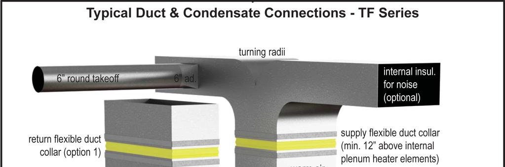
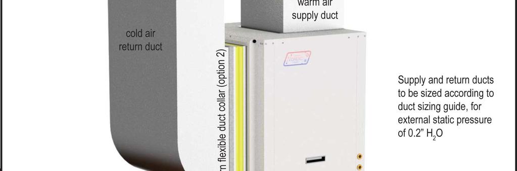
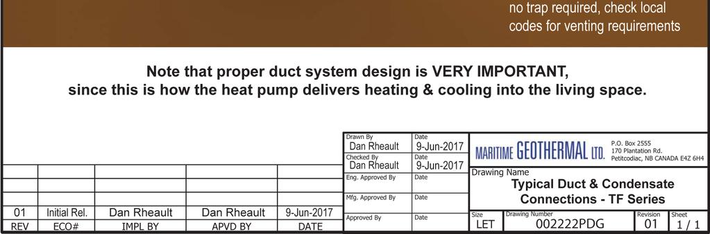
37 Ductwork Duct Systems - General Ductwork layout for a heat pump will differ from traditional hot air furnace design in the number of leads and size of main trunks required. Air temperature leaving the heat pump is normally 95º -105ºF (35-40ºC), much cooler than that of a conventional fossil fuel furnace. To compensate for this, larger volumes of lower temperature air must be moved and consequently duct sizing must be able to accommodate the greater airflow without creating a high static pressure or high velocity at the floor diffusers. A duct system capable of supplying the required air flow is of utmost importance. Maritime Geothermal Ltd. recommends that the external static pressure from the duct system be kept below 0.2 inches of water total. In some instances the number of floor diffusers will actually double when compared to the number that would be used for a hot air oil-fired furnace. Refer to following tables. 1. Generally allow 100 cfm for each floor grill. 2. All leads to the grills should be 6'' in diameter (28sq.in. each). 3. The main hot air trunks should be at least 75% of the square surface area of leads being fed at any given point. 4. Return air grills should have a minimum of the same total square surface area as the total of the supply grills. 5. The square surface area of the return trunks should equal the square surface area of the grills being handled at any given point along the trunk. It is VERY IMPORTANT that all turns in both the supply trunks and the return trunks be made with TURNING RADII. Air act like a fluid and, just like water, pressure drop is increased when air is forced to change direction rapidly around a sharp or irregular corner. It is recommended that flexible collars be used to connect the main trunks to the heat pump. This helps prevent any vibrations from travelling down the ductwork. If a plenum heater is installed, the collar should be at least 12 away from the heater elements. If desired, the first 5-10 feet of the main supply trunks can be insulated internally with acoustical duct insulation to further inhibit any noise from the unit from travelling down the ductwork. If a plenum heater is installed, insulation should not be placed within 12 of the heater elements. Drawing PDG shows a typical installation. Duct Systems - Grill Layout Most forced air heating systems in homes have the floor grills placed around the perimeter of the room. Supply grills should be placed under a window when possible to help prevent condensation on the window. As mentioned in the previous sub -section, supply grill leads should be 6'' in diameter (28 square inches each) to allow 100 cfm of airflow. In a typical new construction, there should be one supply grill for every 100 square feet of area in the room. When rooms require more than one grill, they should be placed in a manner that promotes even heat distribution, such as one at each end of the room. It is always a good idea to place a damper in each grill supply or place adjustable grills so that any imbalances in the heat distribution can be corrected. The total number of supply grills available is based on the heat pump nominal airflow. The table shows the number of grills recommended per heat pump size. TABLE 14 - Heat Pump Size vs. Hot Air Grills Model Size (tons) # of Grills (@100 cfm) Return grills should be mounted on the floor. At minimum they should be the same size as the supply grill, it is highly recommended that they be 25% to 50% larger than the total supply. They should be placed opposite the supply grills when possible to ensure distribution across the room. For rooms requiring more than one supply grill, it may be possible to use one larger return grill if it can be centrally positioned opposite of the supply grills, however it is preferred to have one return for each supply to optimize heat distribution across the room. Ducted Air Thermostat Location Most homes are a single ducted air zone with one thermostat. The thermostat should be centrally located within the home, typically on the main floor. It should be placed away from any supply grills, and should not be positioned directly above a return grill. Most installations have the thermostat located in a hallway, or on the inner wall of the living room. It should be noted that most homes do not have any supply ducts in the hallway. This can lead to a temperature lag at the thermostat if there is very little air movement in the hallway, causing the home to be warmer than indicated by the thermostat. Plenum Heater The plenum heater will be usually installed inside the heat pump, as described in the Installation Basics section. If the blower is installed in the side discharge position, the plenum heater will be installed in the discharge ductwork outside the unit, at least 12 away from any flexible duct collars. There is an accessory plenum heater with a wider cage profile available that is more suitable for duct installation. Page MAN-01
38 002362MAN-01 Page 38
39 TABLE 15 - Duct Sizing Guide (external static of 0.20 H 2 O) Airflow (cfm) Minimum Duct Area (sq.in) Diameter (in) Rectangular Equivalents (in) Return Air Diameter (in) x 10 3 x x 6 4 x x 5 ` x 10 3 x x 6 4 x x x 10 4 x 8 5 x x x x 14 4 x 11 5 x x x x 15 5 x 12 6 x 10 7 x 8 8 x x 15 5 x 12 6 x 10 7 x 8 8 x x 15 6 x 12 7 x 10 8 x x x 15 6 x 12 7 x 10 8 x x x 15 7 x 13 8 x 11 9 x x x 18 8 x 16 9 x x x x 18 8 x 16 9 x x x x 22 9 x x x x x x 22 9 x x x x x x x x x x x x x x x x x x x x x x x x x x x Airflow (L/s) x x x x x x x x x x x x x x x x x x x x x x x x x x x x x x x x x x x x x x x x x x x x x x x x x x x x x x x x x x x x x x x x x x x x x x x x x x x x x x x x x x x x x x x x x x x 37 Page MAN-01

40 Operation BACnet Control If controlling the system via the BACnet interface, skip the entire Operation section. In this case, see the BACnet Interface section later in this manual for network specification and BACnet object names. Air Thermostat Operation Demand for room heating or cooling through the ducted air system will come from a 24V 3H/2C room thermostat, described in the Wiring section. Refer to the thermostat s manual to set it up for 2-stage heat pump with electric backup, and for details on thermostat operation. In heating dominant climates, better cooling mode dehumidification can be achieved by disabling compressor stage 2 in cooling. Then cooling mode will always operate at 67% compressor capacity, and longer run times will result. This setting must be made through the PC App s Control Panel; see PC Application (PC App) section. Hydronic Temperature Control One of the features of the TF s GEN2 Control Board is built in aquastat functionality known as Setpoint Control. This is an internal routine to sample the indoor loop s water OUT temperature to determine if hydronic heat is required; both water IN and OUT temperatures are measured using sensors on water lines inside the unit. The indoor circulator pump is turned on at regular intervals to refresh the water temperature. If sampling is not desired, there is the option to use an external accessory temperature sensor. There is also provision to connect an external aquastat or controller instead of using this routine, for example if two water loops with different setpoints are being heated. 1. Hydronic Heating: Setpoint Control It is recommended that this method be used to control the system s hydronic heat demand since it eliminates the need for an external temperature sensor or aquastat. There are two options for Setpoint Control, Indoor Loop (ICR) method and HTS/CTS method. lator is ON, OFF or SAMPLING. The default sampling times are 2 minutes ON and 6 minutes OFF. The LCD display will also indicate when the ICR is sampling (ON). The Timer Override button will reduce the countdown timer to 10 seconds. See below, and also the PC Application (PC App) section for full screenshots of the various windows. Setpoint Control Method 2 - External (HTS/CTS) When this method is used, no indoor circulator control for temperature sampling will occur. It requires an external temperature sensor placed in a dry well in the top of the buffer tank. Its value is displayed in the Hot Tank box on the PC App s View --> Setpoint Control screen. If this temperature shows NC, then either the probe is not connected to the board or there is a problem with it. A 10K Type 7 (or Type 3) NTC thermistor along with a 10K 1% or better resistor must be connected to the control board in order to use the External HTS/CTS method. Connect the sensor to the AI_5 input as shown above and on the wiring diagram (SCH) in the Model Specific Information section. Remove the AI_5 jumper on the control board. For both setpoint control methods, water setpoint is controlled through the LCD display or PC App (View-->Setpoint Control) as shown on next page. Setpoint Control Method 1 - Indoor Loop (ICR) This is the default method and uses the Indoor OUT temperature probe inside the unit for temperature control. Its value is displayed in the Hot Tank Temperature box on the PC App s View --> Setpoint Control screen. If this temperature shows NC, then either the probe is not connected to the board or there is a problem with it. The heat pump will cycle the indoor circulator on and off when the unit is idle or in air heating/cooling mode, in order to sample the water temperature. When hydronic heating mode ends, the indoor circulator will continue to run for 30 seconds. It will then cycle with an OFF time and ON time as set by the Set ICR Sampling popup which appears when SET is clicked on the View --> Setpoint Control screen. The timer counts down the time remaining before the next switch between ON/ OFF. The indoor circulator indicator will indicate when the circu MAN-01 Page 40
 Measured water temperature Click up/down arrows to adjust values Indicators will turn on")

41 The Setpoint Control screen looks like this for both Method 1 (Indoor Loop) and Method 2 (HTS/CTS). Set indoor circulator ON/ OFF sampling intervals Reduce countdown timer to 10s Set units (STANDARD or METRIC) Measured water temperature Click up/down arrows to adjust values Indicators will turn on when a demand occurs WARNING: When switching to Manual Override mode, the Activation no longer responds to the Setpoint Control values (i.e. if a stage is on it will not turn off when the setpoint is reached. Go to the Control Panel to turn demand ON/OFF with the Stage buttons when in Manual Override Mode. TABLE 16 - Typical Temperature Settings Outdoor reset table only appears when enabled by button at top of screen Stage 1 Stage 2 Stage 3 Item F C F C F C Setpoint Delta Activation * Delay 10 minutes *Activation is determined by the Setpoint and Delta values If the in-floor heating design is well done, the heating setpoints may be able to be lowered. They should be set to lowest value that still maintains an acceptable comfort level in order to achieve maximum hydronic mode efficiency. Increasing Delta values will also increase efficiency due to longer runtimes. and hence a reduced number of compressor starts. Outdoor Reset When Control Source HYD is set to Setpoints, an optional Outdoor Reset control algorithm is available for heating mode. This reduces the heating temperature setpoints at warmer outdoor temperatures, as measured by accessory outdoor temperature sensor. To enable it, first enable the outdoor sensor in the PC App s Tools-->Configuration window. Then click on the Outdoor Reset button at the top of the Setpoint Control window. The button will change to say Enabled, the indicator will come on and the Outdoor Reset table will appear. The Outdoor Reset Table is created by subtracting the value of the Outdoor Reset Factor from the setpoints for each table row. The original setpoints as set in the left hand column are located in table row 0 (<10F). The next row down equals the row above minus the Outdoor Reset Factor. The row in use will be shown in red. The original setpoints are the hottest temperature desired. The calculated row setpoints will decrease as the outdoor temperature rises, and increase back towards the original setpoints as the outdoor temperature drops. This improves system efficiency by maintaining a lower tank temperature when hotter tank temperatures are not needed due to the warmer weather. 2. Hydronic Heating: Signals Control In this control method, hydronic heating demand comes from an external device, like a 2-stage aquastat, combination of aquastats, or other controller with a dry contact that relays a 24VAC signal. See Wiring section. The stage 1 and 2 settings shown in the previous table may be used for the aquastat. The settings may be changed as desired; however stage 1 setpoint for heating should not exceed 120 F (49 C). Exceeding this limit will cause the heat pump operating pressures to approach the safety control settings, possibly causing nuisance shutdowns. If only floor zones are being heated, it is highly recommended to drop each of the heating setpoints by 10 F (5 C) for increased efficiency. When using Signals Control, the backup tank element thermostat can be set to maximum, allowing the electric elements to be controlled by an external contactor placed in the power supply connections (see Wiring section). The contactor can be connected to stage 2 of the heating aquastat via an optional 0-2hour timer. Alternatively, if the buffer tank with elements has a digital controller, it can be set to run independently, if its temperature setpoint is set to below that of the heat pump s stage 2 setpoint (stage 3 in the preceding table). Page MAN-01


42 PC Application (PC App) NOTE: Before using the PC Application, refer to Appendices for installation instructions for the PC Application and USB driver for the COM port. Both must be installed in order to run the PC App and communicate with the control board. Connect a USB cable between the PC and the control board USB connector located at the bottom center of the board. Use the Windows Start menu to launch the PC App. You should see a screen similar to the one below. The revision of the PC APP is shown in the top left corner of the screen. Click the Connect button to begin communications with the control board. Once connected, the menus and buttons will become accessible, the number of Objects available and Read should appear (they should be the same) and the Polling LED will begin to flash. The PC time and date will appear at the bottom left corner of the screen. Clicking on Control Board Date and Time will display the current control board date and time. If the date and time need to be adjusted, click on menu Tools Set Date and Time. The control board date and time will be set to that of the PC. PC Application Menus The following pages describe the PC APP s menus in detail. There are six menus: File, View, Graphs, Tools, Windows, Help. File Menu: This menu handles page arrangements. If one or multiple pages are open and arranged as desired for viewing, this page arrangement may be saved and re-used the next time the PC APP is used. File-->Open: Opens a saved page arrangement. File-->Save: Saves the current page arrangement under the current name. File-->Save As: Save the current page arrangement under a new name. File-->Exit: Exits the PC Application. Windows Menu: This menu is used to arrange windows (pages), or to bring a particular window to the front. Windows-->Cascade: Windows-->Tile Vertical: Windows-->Tile Horizontal: Windows-->Close All: Arranges windows one in front of the other each with a small right and down offset from the last. Arranges windows side by side, stretching them fully from top to bottom. Arranges windows up and down, stretching them fully from left to right Closes all open windows. Help Menu: This shows information about the PC Application. Help-->About: Displays the window shown to the right MAN-01 Page 42


43 View Menu: This menu handles all of the operational viewing screens. Clicking on the View submenus will open the page in the PC APP s frame. The next few pages of the manual show screenshots of each of the pages along with some descriptions of what is on each page. View-->Control Panel: The main control panel window will open, shown below. Heat pump model information Click to enable or disable stage 2 air cooling (disable for better dehumidification) Operational status of the heat pump system Manual controls are enabled when in MANUAL OVER- RIDE mode. Indicators show the demand from the control system. Click to change from Air to Hydronic priority (can also be done from Configuration screen) Click to disable the unit and fully open electric valves to allow work to be done to the refrigeration system. Indoor fan information. Click SET to adjust airflows. Compressor stage ON/OFF status Stage run time indicators Auxiliary information, air and hydronic. Status lights indicates when in use. Refrigeration system pressure data, along with alarm indicators. Refrigeration system temperature data. Indoor EEV. Status light indicates when in use. Reversing valves. Status light indicates when in use. Set airflow reduction % when AR dry contact is made. Outdoor temperature (requires accessory sensor) Short Cycle timer and override button for when unit is being serviced. View-->Setpoint Control: Shows the on-board temperature control screen. This screen is only available when Control Source HYD on the Configuration Page is set to Setpoints (not BACnet). Refer to the Operation chapter earlier in this manual for details. View-->Alarms, Limits and Faults The alarms page has four tabs: 1. ALARMS - Current alarm status, alarm count, high and low refrigeration alarm cutout values, and short cycle timer. 2. ALARMS LIST - List of alarms that have occurred since the PC APP has been operating (this will be lost when the PC is disconnected from the control board.) 3. LIMITS - Limits in effect which prevent compressor operation but that do not cause an alarm. 4. FAULTS - List of board hardware faults. Page MAN-01

44 View-->Alarms, Limits and Faults (ALARMS Tab): NOTE: Greyed out Alarms in the PC APP are not applicable to the system setup and are not monitored by the control board. NOTE: Refer to Alarms and Faults screenshot below to see which alarms have a count. Alarms without a count: These alarms only occur one time at which point they immediately create a Permanent Alarm. Alarms with a count: Master Alarm: Permanent Alarm: Low Pressure: High Pressure: Compressor Monitor: Compressor Status: Phase Monitor: Low Charge: Loss of Charge (LOC): When an alarm occurs the compressor will stop, the alarm count will increase and the Short Cycle Timer will start. When the SC Timer expires the compressor will re-start. If no further alarms occur within Count Reduce Time, the alarm count will be reduced by 1. If another alarm occurs within Count Reduce Time (see Configuration Page) the count will increase by 1. If alarms continue to occur, when the alarm count reaches the Maximum Count value a Permanent Alarm will occur. This alarm occurs when any permanent alarm occurs. It is used to simply indicate that there is an alarm. The compressor will be locked out until the Permanent Alarm is manually reset either by cycling the power or clicking on the RESET button A low pressure alarm occurs when the suction pressure drops to or below the Low Pressure Cutout value. The low pressure is checked just before a compressor start, if it is OK the compressor will start, otherwise an alarm will occur. When the compressor starts, the low pressure alarm will be ignored for the number of seconds that Low Pressure Ignore is set to, after which the low pressure alarm will be re-enabled. This allows a dip in suction pressure below the cutout point during startup without causing a nuisance alarm. A high pressure alarm occurs when the discharge pressure rises to or above the High Pressure Cutout Value. This alarm occurs when the compressor protection module sends a fault signal to the control board, generally due to the compressor windings overheating. (Most residential models do not have compressor protection modules.) This alarm occurs when there is a current draw on the compressor but no call for the compressor to be on (i.e. welded contactor) or when there is a call for the compressor to be on but there is no compressor current draw (i.e. manual high pressure control is open or contactor failure). Requires current sensor accessory. This alarm occurs when the Phase Monitor detects a fault condition and sends a fault signal to the control board. For three phase units only and requires Phase Monitor accessory. This alarm occurs if the EEV has been at >99% for 20 minutes within first hour of a cycle. This alarm occurs if both the low pressure and high pressure sensors are below 30 psig (207kPa). Outdoor WV: Outdoor loop water valve end switch did not close (open loop only). Go the Alarms Troubleshooting section of the Troubleshooting chapter of the manual to address alarm issues. This button will erase all alarms and alarm counters, including a permanent alarm. Master Alarm occurs when any alarm occurs. WARNING: Repeated resets can freeze and rupture heat exchangers, ruining the heat pump and voiding the warranty. The source of the alarm should be determined before resetting the unit if possible or during operation after a reset. Low Pressure cut out. High Pressure cut out. Greyed out alarms are not applicable to the system. Short Cycle Timer counts down time until the next compressor start is allowed. This button will reduce the short cycle timer value to 10 seconds MAN-01 Page 44


45 View-->Alarms, Limits and Faults (ALARMS LIST Tab): This tab show a history of alarms that have occurred since the PC APP was connected to the control board. This list will be lost when the PC APP is disconnected. Each alarm that occurs while the PC APP is connected to the control board will appear here. The alarm type and a time stamp will be shown. The alarms list will be erased when the PC APP is disconnected from the control board. This button will erase the alarm events in the Alarm List. View-->Alarms, Limits and Faults (LIMITS Tab): This tab shows temperatures that are out of limits but have not caused an alarm. These limits are shown on the Tools-->Configuration page. Page MAN-01


46 View-->Alarms, Limits and Faults (FAULTS tab): This tab shows hardware faults that could occur. If one of these faults occurs there may be a problem with the control board hardware, with LCD Display and buttons, or with a sensor. If a fault occurs, some things to try: Turn the power to the heat pump off for 20 seconds and then back on again. Use the menu item Tools-->Reset to Factory Defaults. If this clears the fault then the system configuration will have to be set up again. For LCD Display or Menu Button faults, turn off the power, disconnect and reconnect the cable between the LCD display board and the control board, then turn the power back on again. If the fault persists then there is most likely a hardware problem, and the sensor, control board, or LCD display board will need to be replaced. IMPORTANT NOTE: If the Indoor OUT (I_OUT) probe is faulty or disconnected, neither hydronic heating nor the auxiliary will operate if using Setpoint Control. They will continue to operate under Signals or BACnet control. Greyed out do not apply. Fault Indicators View-->Stage Stats: The compressor information: number of starts, run hours and starts per hour. Erase the compressor statistics (only for if a compressor should need to be replaced). View-->Set Stage 2 Delay: Sets the delay before stage 2 is engaged on a stage 1 demand. ( 0 = no stage 2 engaged on a stage 1 call) MAN-01 Page 46
.")
.")
.")
 or 0-10VDC (channel jumper on board OFF).")

47 View-->Water Lines Shows the water line temperatures. View-->Digital Inputs Shows the digital inputs and their individual status (ON/OFF). They may be individually controlled when in Manual Override Mode in order to facilitate troubleshooting. View-->Digital Outputs Shows the digital outputs and their individual status (ON/OFF). They may be individually controlled when in Manual Override Mode in order to facilitate troubleshooting.. View-->Analog Inputs Shows the Analog inputs and their individual settings and values. Click on the EDIT button to modify the blue boxes (button will now say SAVE). For each channel a name may be selected (up to 16 characters), and the multiplier and Offset values may be set to accommodate the connected sensor scaling. Signals may be 4-20mA (channel jumper on board ON) or 0-10VDC (channel jumper on board OFF). A variety of units are also available for selection of common measurement types. Click on SAVE to save the changes. Values are kept even when power is removed from the unit. View-->PWM Channels Shows the PWM channels and their individual status (0-100%). They may be individually controlled when in Manual Override Mode in order to facilitate troubleshooting. EMW-series does not use any PWM channels. Page MAN-01


48 Graphs Menu: This menu is a list of the available graphs. Graphs are real-time and show a time stamp of when the recording started as well as a current time which will show up if the graph is screen captured. Each graph has a CLEAR button which will erase the stored data and restart the graph. There is also a master CLEAR ALL GRAPHS button at the top right of the PC APP; this will clear all open graphs and re-start them all simultaneously to keep them in sync with each other. The refresh rate for the graphs is also located at the top right of the PC APP. TIP: To screen print a graph and save it as a picture, press Print Screen on the keyboard and then paste into MS Paint or other graphics program. Select the desired graph with the selection tool and copy it to a new MS Paint, then save the file as the desired name. ON/OFF status of the system control signals (demands). ON/OFF status of heating and cooling modes. EEV position and resulting superheat. Suction temperature. Suction and discharge pressures. Evaporation and condensing temperatures. 2 tabs: one for indoor IN/OUT/Delta T, and one for outdoor IN/OUT/Delta T. Discharge pressure vs tank temperature. All analog input channels (0-10VDC or 4-20mA). All PWM / 0-10VDC output channels and one PWM / 0-10VDC input channel. For future use. Below is an example of a typical graph screen. Items that are checked will be plotted, unchecked items will not. The graph screens show the time the graph started as well as the current time to time stamp the graph when screen printed. Graph Name Refresh Rate CLEAR button erases all graph data. Graph start time Graph printed time Check boxes to select which items are graphed Current values Primary Y axis on the left, secondary Y axis on the right. X axis = Number of samples. Elapsed time = Number of Samples x Refresh Rate. e.g. 20 samples x 1 second refresh = elapsed time of 20 seconds MAN-01 Page 48

49 Tools Menu: This is where various tools for system setup and monitoring are located. Tools-->Configuration (System Configuration tab): This is where the system setup is done. Settings should only be changed by a person who has a good understanding of system operation. Improper settings could cause the system to operate poorly or not at all. Green when parameters have been updated, red during the update Firmware revision can also be seen on the LCD during power up Firmware update: see Appendix POR: reset control system as would be done by cycling power Enable/Disable the compressor (does not affect auxiliary heat). Units are shipped as Disabled to prevent an unintentional compressor startup. Model Configuration section to select the system type Select model series, size, & refrigerant (refer to unit nameplate; will be set from factory) Loop type as hardware selected by the closed loop jumper plug or open loop water valve harness Low pressure cutouts determined by loop type (55 or 75 psig) Compressor: 2 stage ( T in unit model number) or 1 stage ( S in unit model number) Jumper configuration section to select system options. Greyed out means N/A. automatically selected High pressure cutout determined by refrigerant type Temperature limits determined by series and loop type Selects how the air heating/ cooling functions will be controlled, either BACnet or Signals. The Enabled indicators show which alarms are enabled Selects how the water heating function will be controlled: BACnet, Setpoints, or Signals. Selects whether or not to use the internal temp sensor (default) or external sensor(s). This is for Setpoint Control operation only. Air or Hydronic priority. Can also be set from button on Control Panel screen. When Summer Setback is enabled: disables stage 3 (AUX), drops setpoints to 70 F (21 C), and decreases temperature sampling frequency to 2 days. Can also be set through LCD. Enable outdoor temperature sensor accessory for Outdoor Reset function If Control Source HYD is set to BACnet, set communication parameters. Disconnect PC App and cycle unit power to register changes to BACnet parameters. If an alarm is mandatory or not available, the Enable button will be greyed out. For optional alarms (requiring Phase Monitor or Current Sensor accessories) the Enable button will be available; click to enable. Page MAN-01

50 Tools-->Configuration (Alarms and Delays tab): Click on the UP/DOWN arrows to change the value, noting that values have both a low and high limit. The number of minutes before the unit can start again after a normal shutdown. The number of minutes before the unit can start again after various alarm shutdowns Maximum Count is the number of alarms allowed before a permanent lockout occurs. Count Reduce Time is the number of hours after which the alarm count is reduced by 1 if no other alarm occurred within the timeframe. The minimum off time when switching between heating and cooling cycles Ignore On Start is the number of seconds an alarm will not be monitored after a compressor start occurs. Overrides the alarm indicating that the water valve end switch failed to close (Outdoor WV/ODFLOW) Items that do not apply to the model are greyed out MAN-01 Page 50


51 Tools-->Calibration: Generally there is no need for calibration. The suction and discharge pressures may be calibrated in increments of 1 psi if there is a discrepancy in the readings when compared to a known good reference. Temperature sensors may be adjusted in increments of 0.1 F. There is an AUTO CALIBRATION routine in the program that continually calibrates the temperatures sensors against an on board reference resistor by applying an offset to the temperature sensors. Calibration adjustments made here are in addition to the Auto Calibration routine. Current values in standard and metric. Calibration adjustments Temperature Auto Calibration information. The offset is applied to all temperature sensors. Calibration adjustments made to each sensor are in addition to the Auto Calibration values. Click on the RESET ALL CALIBRATIONS button to clear all calibration data. A popup window will appear for confirmation. Tools-->Reset to Factory Defaults: This will reset all parameters to default values. THE SYSTEM MUST BE RECONFIGURED AFTER A RESET IS PERFORMED. A reset will default the system to a two stage ATW Series Size 65 with Signals as the control source. Calibrations, alarm delays, analog configurations, compressor statistics, and Setpoint Control values will be returned to defaults as well. Tools-->Set Date and Time: This will synchronize the date and time of the control board with the computer s date and time, and will be necessary for new units or units that have been powered off for several days or more. The date and time of both the computer and the control board are shown in the status bar at the bottom of the PC App. Page MAN-01


52 Tools-->Datalogging (Datalog tab): The datalog rate is set via the dropdown box at the top right of the PC App main window. Starting with firmware version 2.85, a log will be recorded at the datalog rate whenever the heat pump is powered on, making it easy to compare datalogs from multiple units. The maximum number of datalog records is 32,224, which will take 45 days to fill up at the default recording rate of 2 minutes. Note that loading datalogs is time-consuming. It is suggested to leave the # of LOGS at 25 until it is shown that the start date selected is suitable. Loads the # of LOGS beginning from the earliest date Loads the # of LOGS beginning from the selected date. Erases the screen only Exports the data to a file. Erases all logged data in the control board and resets the log count to 0. Clicking anywhere on a row will update all LEDs to show the status at the time of that log record. Tools-->Datalogging (Enable/Disable tab): Click on the checkboxes to customize which columns are shown/hidden in the datalog table. Tools-->MODBUS: For future use. Tools-->Objects: This is a window to display the runtime data, which is not stored when the power is turned off. No changes are possible MAN-01 Page 52


53 Tools-->Parameters: WARNING! The Parameters page is for advanced use only. Changing parameter values can cause the system to stop functioning properly. The parameters page shows all configurable memory spaces with their name and current value and allows them to be edited directly. To change a parameter value type in the new value and press ENTER. Clicking on menu item Tools-->Parameters will display this warning. Click on YES to open the parameters page. Click this button to reload the table with the values from the control board memory. Type in the new value and press ENTER, the confirmation popup will appear, click on OK. Tools-->SYSTEM TIMERS: This page shows all internal timers by name along with their current values. Tools-->Jumpers: This page shows internal jumper configurations, for developers. Page MAN-01


54 LCD Display & Menus These are examples of the unit status and operating data displayed when at the message display level (top level). Pressing ENTER will enter into the menu levels beginning with the Main Menu. Pressing OK will toggle between message auto scroll and manual scroll modes. UP and DOWN do not do anything if in auto scroll mode; they cycle through the messages if in manual scroll mode. 2x16 LCD Display ENTER button: Use this to push down to the next menu level. Also saves value if at parameter menu level. UP button: Use this to scroll up through the items available at a menu level. DOWN button: Use this to scroll down through the items available at a menu level. OK/EXIT button: Use this to come back up one menu level. Also saves value if at parameter menu level. Main Menu: This is a list of the various tools are used for system setup and monitoring. The table shows what is displayed based on each press of the ENTER button starting at the Main Menu level. ENTER (From Main) Setpoint Control (only if using Setpoint control) ENTER (First Press) ENTER (Second Press) Setpoints Heating ENTER (Third Press) Stage 1 Setpoint Stage 1 Delta Stage 2 Setpoint Stage 2 Delta AUX (S3) Setpoint Description Stage 1 stops when water temperature rises to this point. Stage 1 starts when water temperature drops below setpoint by this amount. Stage 2 stops when water temperature rises to this point. Stage 2 starts when water temperature drops below setpoint by this amount. Stage 3 stops when water temperature rises to this point. Stage 3 time delay starts when water temperature drops below setpoint by this AUX (S3) Delta amount. (Stage 3 starts immediately if time delay is set to 0). AUX (S3) Delay Delays Stage 3 start by timer amount. Outdoor Reset (only if enabled) Temperature factor to use in the outdoor reset table. Summer Setback Enable Setback? Enable Enable summer setback. Disable Disable summer setback. System EN/DIS Enable System? Disable Disable compressor, auxiliary and ICR. Enable Enable compressor, auxiliary and ICR MAN-01 Page 54
55 ENTER (From Main) ENTER (First Press) Main Menu Continued ENTER (Second Press) ENTER (Third Press) Description Service Mode Service Mode? No Do not enter Service Mode. Yes Enter into Service Mode. EEV Control EEV1 (Local) Auto/Manual Auto Puts EEV in Auto mode Manual Puts EEV in Manual mode Manual Position EEV Position (%) Sets EEV to manual position Configuration Priority Air Sets the priority to air modes. Hydronic Sets the priority to hydronic mode. Control AIR BACnet BACnet control see BACnet section. Signals Hardwired Signal control. Control HYD BACnet BACnet control see BACnet section Signals Hardwired Signal control Setpoints On-board aquastat control see SET- POINT CONTROL section. Outdoor Reset Enable Enables Outdoor Reset functionality Disable Disables Outdoor Reset functionality Outdoor Ambient Enable Enables the outdoor temperature sensor. Disable Disables the outdoor temperature sensor. Setpoints Method ICR Use Indoor Circulator Relay sampling HTS/CTS Use external temperature sensors Time Delays Short Cycle Delay (min) Short-cycle timer delay in minutes Heat/Cool Delay (min) Heat / Cool timer delay in minutes Units Standard Standard units Metric Metric units (does not affect calibration units) Set Time Hours Hours value Set the system hours. Minutes Minutes value Set the system minutes. Set Date Day Day value Set the system day. Month Month value Set the system month. Year Year value Set the system year. Calibration Suction 1 calibration adj. Calibration in 1PSI intervals. Discharge 1 calibration adj. Calibration in 1PSI intervals. Vapour Line 1 Outdoor Ambient calibration adj. Calibration in 0.1 F intervals calibration adj. Calibration in 0.1 F intervals Outdoor IN Temp calibration adj. Calibration in 0.1 F intervals Outdoor OUT Temp calibration adj. Calibration in 0.1 F intervals Indoor IN Temp calibration adj. Calibration in 0.1 F intervals Indoor OUT Temp calibration adj. Calibration in 0.1 F intervals NOTE: Calibration is generally not required. Pressure sensors may be calibrated against a known source if needed. All temperature sensors have an Auto Calibration feature. Page MAN-01
56 BACnet Interface The BACnet interface is an MS/TP connection via RS-485 twisted pair. There is a termination jumper if required to terminate the connection. It is marked as TERM on the control board, and is located just above the BACnet connector. The connector on the control board is a three wire removable screw connector. The signals are as follows: A: Communications line (+) (right pin) B: Communications line (-) (middle pin) C: Ground connection (left pin) Vendor: Maritime Geothermal Ltd. Vendor ID: 260 Model Name: MGT GEN2 Control Board The following parameters can be set via the LED Display Configuration Menu or via the PC APP Configuration Page. 1) Baud rate 2) Instance number 3) MAC address The data is available regardless of the selected control method. In order to control the unit via the BACnet interface, set the Control Source to BACnet either by using the PC APP configuration page or the display menus. The following tables provide a list of the objects applicable to this model series, along with a description of each. Note that there may be other objects available that do not apply to this model. TABLE 17 - BACnet OBJECTS - CONTROL SIGNALS (READ/WRITE) Name Data Type ID Property Description SYSTEM_O Binary Value BV2 Present Value Switch to air cooling mode (RV#1). Inactive=HEATING, Active=COOLING SYSTEM_Y1 Binary Value BV3 Present Value Demand for air heating or cooling modes (active is on) SYSTEM_Y2 Binary Value BV4 Present Value Demand for stage 2 air heating or cooling modes (active is on) SYSTEM_W2 Binary Value BV5 Present Value Demand for air auxiliary (plenum heater) (active is on) SYSTEM_G Binary Value BV6 Present Value Demand for blower recirculation (active is on) SYSTEM_AR Binary Value BV7 Present Value Airflow reduction (active is on) SYSTEM_Y1A Binary Value BV0 Present Value Demand for water heating mode (active is on) SYSTEM_Y2A Binary Value BV1 Present Value Demand for stage 2 water heating mode (active is on) BACnet_Units Binary Value BV9 Present Value Select the units to use for the BACnet objects Note: object names may be subject to change without prior notice. TABLE 18 - BACnet OBJECTS - OPERATION MODE Description (Read Only) Name Data Type ID Present Value Description Operation Mode Analog Value AV5 - Integer value represents operating mode. 0 Air heating 1 Air cooling 2 Hydronic heating 9 Air heating OFF 10 Air cooling OFF Note: Object is type Analog Value but value will always be an integer value. Note: Objects may be subject to change without prior notice MAN-01 Page 56
57 TABLE 19 - BACnet OBJECTS - DATA (Read Only) Name ID Property Units Description Data Type Analog Input AI0 (Comp1_Current) AI0 Present Value Amps Compressor current draw (AI0) - requires accessory AI1 (Comp2_Current) AI1 Present Value User User defined (0-5VDC or 4-20mA) AI_2 AI2 Present Value User User defined (0-5VDC or 4-20mA) AI_3 AI3 Present Value User User defined (0-5VDC or 4-20mA) AI_4 (CTS) AI4 Present Value User User defined (0-5VDC or 4-20mA) AI_5 (HTS) AI5 Present Value degf (degc) Tank temperature from sensor (AI5) - requires accessory LPS1 AI6 Present Value PSIG (kpa) Low pressure value (suction pressure) HPS1 AI7 Present Value PSIG (kpa) High pressure value (discharge pressure) EVAP1 AI8 Present Value degf (degc) Evaporating Temperature COND1 AI9 Setpoint Value degf (degc) Condensing Temperature Suction Line 1 AI10 Present Value degf (degc) Suction line temperature Superheat 1 AI11 Setpoint Value degf (degc) Superheat EEV1 Position AI12 Present Value % EEV position (% open) LPS2 AI13 Present Value PSIG (kpa) N/A HPS2 AI14 Present Value PSIG (kpa) N/A EVAP2 AI15 Present Value degf (degc) N/A COND2 AI16 Setpoint Value degf (degc) N/A Suction Line 2 AI17 Present Value degf (degc) N/A Superheat 2 AI18 Setpoint Value degf (degc) N/A EEV2 Position AI19 Present Value % N/A Outside Ambient AI20 Present Value degf (degc) Outdoor Ambient temperature - requires accessory O_IN AI21 Present Value degf (degc) Outdoor IN temperature O_OUT AI22 Present Value degf (degc) Outdoor OUT temperature I_IN AI23 Present Value degf (degc) Indoor IN temperature I_OUT AI24 Present Value degf (degc) Indoor OUT temperature Data Type Analog Value PWM_IN AV0 Present Value % PWM input (from external source) PWM1 (OD Fan) AV1 Present Value % PWM output value (spare) PWM2 AV2 Present Value % PWM output value (spare) PWM3 (OV2) AV3 Present Value % OV2 - PWM or 0-10VDC for Outdoor Loop water valve PWM4 (IV2) AV4 Present Value % IV2 - PWM or 0-10VDC for Indoor Loop water valve Operation Mode AV5 Present Value N/A Unit operation mode - refer to Operation Mode Table Data Type Binary Output STAGE1 BO0 Present Value N/A Compressor contactor STAGE2 BO1 Present Value N/A Compressor stage 2 solenoid ICR (Indoor Circ) BO2 Present Value N/A Indoor circulator control DO0 (OV1) BO3 Present Value N/A OV1 (to 24VAC Outdoor Loop water valve) DO1 (IV1)) BO4 Present Value N/A IV1 (to 24VAC Indoor Loop water valve) DO2 (HYD_AUX) BO5 Present Value N/A Hydronic Auxiliary DO3 (AUX_ONLY) BO6 Present Value N/A Hydronic Auxiliary Only (without compressor) PHS1 BO7 Present Value N/A Air plenum heater stage 1 PHS2 BO8 Present Value N/A Air plenum heater stage 2 Data Type Binary Value CONTROLS (LOC/REM) BV9 Present Value N/A Control Indicator, 0 = Local, 1 = Remote (BACnet) Outdoor Flow BV10 Present Value N/A Outdoor loop water valve Indoor Flow BV11 Present Value N/A Indoor Loop flow switch - requires accessory Phase Monitor1 BV12 Present Value N/A Phase Monitor Stage 1 Phase Monitor2 BV13 Present Value N/A N/A Comp Monitor1 BV14 Present Value N/A N/A Comp Monitor2 BV15 Present Value N/A N/A Note: available objects may be subject to change without prior notice. Page MAN-01
58 TABLE 20 - BACnet OBJECTS - ALARM Descriptions (Read Only) Name Data Type ID Description AI0 (Comp1 Current) Analog Input AI0 Stage 1 Status alarm (Start / Stop Failure) - requires accessory AI1 (Comp2 Current) Analog Input AI1 N/A LPS1 Analog Input AI6 Low pressure alarm HPS1 Analog Input AI7 High pressure alarm LPS2 Analog Input AI13 N/A HPS2 Analog Input AI14 N/A Outdoor Flow Binary Value BV10 Outdoor loop water valve Indoor Flow Binary Value BV11 Indoor loop flow alarm - requires accessory Phase Monitor1 Binary Value BV12 Phase Monitor alarm - requires accessory Phase Monitor2 Binary Value BV13 N/A Comp Monitor1 Binary Value BV14 N/A Comp Monitor2 Binary Value BV15 N/A Name ID BIT # VALUE* Description Permanent Alarms 1 AV6 - - Bit description is given below. (Present Value) 0 1 Master permanent alarm (occurs when any alarm occurs) 1 3 Low pressure heating mode alarm (suction pressure) 2 5 Low pressure cooling mode alarm (suction pressure) 3 9 High pressure heating mode alarm (discharge pressure) 4 17 High pressure cooling mode alarm (discharge pressure) 5 33 Loss of charge alarm 6 65 Phase monitor alarm - requires accessory Compressor monitor alarm - N/A Status alarm 14 16,385 Outdoor loop water valve 15* 32,769 Indoor loop flow alarm - requires accessory Permanent Alarms 2 AV7 - - N/A (Present Value) Note: Permanent Alarm objects are type Analog Value but values are bit coded and may be decoded as such (integer value). Note * : Value is for a single alarm and reference only. Value includes + 1 for Master Alarm Note: Objects may be subject to change without prior notice MAN-01 Page 58
59 TABLE 21 - BACnet OBJECTS - FAULT Descriptions (Read Only) Name Data Type ID Description AI4 (Cold Tank) Analog Input AI0 N/A AI5 (Hot Tank) Analog Input AI1 Tank temperature sensor faulty or disconnected - requires accessory LPS1 Analog Input AI6 Low pressure sensor faulty or disconnected HPS1 Analog Input AI7 High pressure sensor faulty or disconnected LPS2 Analog Input AI13 N/A HPS2 Analog Input AI14 N/A Suction Line1 Analog Input AI10 Suction line 1 temperature sensor faulty or disconnected. Suction Line2 Analog Input AI17 N/A Outside Ambient Analog Input AI20 Outside temperature sensor faulty or disconnected - requires accessory O_IN Analog Input AI21 Outdoor IN temperature sensor faulty or disconnected. O_OUT Analog Input AI22 Outdoor OUT temperature sensor faulty or disconnected. I_IN Analog Input AI23 Indoor IN temperature sensor faulty or disconnected. I_OUT Analog Input AI24 Indoor OUT temperature sensor faulty or disconnected. Name ID BIT # Value * Description Board Faults AV8 - - Bit description is given below. 0 1 Digital inputs 1 2 Digital outputs 2 4 PWM outputs 3 8 Analog to digital conversion 4 16 Real time clock 5 32 EEPROM memory 6 64 Menu buttons LCD Display Sensor Faults AV9 - - Indicates sensor failures. Bit description is given below. 0 1 Suction line 1 temperature 1 2 N/A 2 4 Outdoor Ambient temperature (ACCESSORY) 3 8 Calibration temperature 4 16 Indoor IN temperature 5 32 Indoor OUT temperature 6 64 Outdoor IN temperature Outdoor OUT temperature N/A N/A Note: Board and Sensor Fault objects are type Analog Value but values are bit coded and may be decoded as such (integer value). Note * : Value is for a single fault and reference only. Note: Objects may be subject to change without prior notice. Page MAN-01
60 Startup Procedure The TF-Series Two-Stage R410a Startup Record located in this manual is used in conjunction with this startup procedure to provide a detailed record of the installation. A completed copy should be left on site, a copy kept on file by the installer and a copy should be sent to Maritime Geothermal Ltd. Check the boxes or fill in the data as each step is completed. For data boxes, circle the appropriate units. Pre-Start Inspection Ductwork: 1. Verify that all ductwork has been completed and is firmly attached to the unit. Verify that any dampers or diverters are properly set for operation of the heat pump. 2. Verify that all registers are open and clear of any objects that would restrict the airflow. 3. Verify that a new air filter is installed and the cover is secured. 4. Verify the condensate drain is connected, properly vented, and free of debris. 5. If a plenum heater has been installed, verify that it is securely fastened. Indoor Loop (Hydronic Loop): 1. Verify that all shutoff valves are fully open and there are no restrictions in the piping from the heat pump to the indoor loop, and that full flow is available to the heat pump. 2. Verify that the entire system has been flooded and all the air has been purged as much as possible. Further purging may be required after the system has been operating for a while. 3. Verify that the loop contains the proper mix of antifreeze (if used) for the intended application. If applicable, record the type of antifreeze and the mixture value on the startup sheet; circle % vol. or % weight. 4. Record the static loop pressure on the startup sheet. Outdoor Loop (Ground Loop): 1. Verify that all shutoff valves are fully open and there are no restrictions in the piping from the heat pump to the ground loop, and that full flow is available to the heat pump. 2. Verify that the entire system has been flooded and all the air has been purged as much as possible. Further purging may be required after the system has been operating for a while. 3. Verify that the loop contains the proper mix of antifreeze for the intended application. Record the type of antifreeze and the mixture value on the startup sheet; circle % Vol. or % Weight. 4. Record the static loop pressure on the startup sheet. Outdoor Loop (Open Loop): 1. Verify there are no leaks in the connections to the unit. Verify the water valve is installed and properly oriented in the water out line. 2. Verify that there is flow control in water out line. Domestic Hot Water (Desuperheater): 1. Verify that all shutoff valves are fully open and there are no restrictions in the piping from the heat pump to the domestic hot water tank. 2. Verify that the entire system has been flooded and all the air has been purged as much as possible. Further purging may be required after the system has been operating for a while. 3. Verify that the brown wire with the insulated terminal is disconnected in the electrical box. Refer to the schematic diagram for more information. Electrical: 1. Ensure the power to the unit is off. Ensure the power to the plenum heater is off if equipped. 2. Verify all high voltage connections. Ensure that there are no stray wire strands, all connections are tight, and the ground wire is connected tightly to the ground connector for the heat pump & plenum heater. 3. Record the circuit breaker size and wire gauge for the heat pump & plenum heater. 4. Verify that the control connections to the unit are properly connected and all control signals are off, so that the unit will not start up when the power is turned on. 5. Verify that the circulator pumps are connected to the proper voltage terminals in the heat pump. Record the voltages of the circulator pumps. 6. Ensure all access panels except the one that provides access to the electrical box are in place. Unit Startup The unit is now ready to be started. The steps below outline the procedure for starting the unit and verifying proper operation of the unit. It is recommended that safety glasses be worn during the following procedures. IMPORTANT NOTE: The unit is shipped with the compressor DISABLED in order to prevent the unit from starting when the power is first turned on. Follow the instructions below in the Preparation section to enable the compressor. When power is on, the LCD display will alternate to show the outdoor temperature (if sensor present), low (suction) pressure, high (discharge) pressure, superheat, EEV position and water in/out temperatures. Preparation: 1. Turn the power on to the heat pump and set the thermostat(s) to OFF. All LED s on the control board should turn on, the LCD display should say MGT GEN2 VERx.xx on line 1 and Zeroing EEV s on line 2. You should be able to hear the EEV moving (a clicking sound) MAN-01 Page 60
61 2. Measure the following voltages on the compressor contactor and record them on the startup sheet: L1-L2, L2-L3, L1-L3. 3. Connect a USB cable between the USB connector on the board and a laptop with the PC App installed (recommended but optional). 4. Select the desired Control Source HYD via the PC APP Configuration Page or via the LCD display Configuration Menu. Set the water setpoints to a low value (e.g. 50 F) to prevent the compressor from coming on in water heating mode. 5. Enable the system either with the PC App s Configuration Page System Enable/Disable button or via the LCD display. Air Heating Mode: 1. Set the air thermostat to heating mode and adjust the setpoint to activate stage 1 and stage 2. The fan should slowly ramp up to speed after the time delay of the thermostat expires (if applicable) and the compressor will start. 2. Check the PC App or LCD Display. The suction and discharge pressures will vary based on the outdoor temperature and indoor air temperature, but they should be PSIG and PSIG respectively for a typical start-up. 3. Monitor the PC App or LCD while the unit runs. Record the following after 10 minutes of runtime: 1. Suction pressure 2. Discharge pressure 3. Duct Return temperature (poke a small hole in the flex collar and insert probe in airstream) 4. Duct Supply temperature (poke a small hole in the flex collar and insert probe in airstream) 5. Duct Delta T (should be between F, C) 6. Outdoor Loop Temperatures: In, Out, & Delta T (should be 5-8 F, 3-4 C) 7. Compressor L1(C) current (black wire, place meter between electrical box and compressor) 4. Adjust the thermostat setpoint to the desired room temperature and let the unit run through a cycle. 5. For units with a desuperheater, turn the power off to the unit. Connect the brown wire with the blue insulated terminal to the compressor contactor as shown in the electrical box diagram. Turn the DHW Switch in the unit post on. Turn the power to the unit on. 6. Verify the DHW IN and DHW OUT temperatures (if applicable) by hand (caution: pipes get hot). If the DHW OUT line does not become hotter than the DHW IN line the circulator is air locked. Bleed the air from the system and check the temperature differential again to ensure there is flow from the circulator. 7. Remove the electrical cover from the plenum heater. Place a current clamp meter around one of the supply wires. Turn on the power to the plenum heater. Adjust the thermostat setpoint to 85 F (29 C). Verify that the current draw increase as each electric heat stage is activated. (10kW has 2 stages, 15kW has 3 stages and 20kW has 4 stages). Air Cooling Mode: 1. Set the air thermostat to cooling mode and adjust the setpoint to activate stage 1 and stage Monitor the PC App or LCD while the unit runs. Record the following after 10 minutes of runtime: 1. Suction pressure 2. Discharge pressure 3. Duct Return temperature 4. Duct Supply Out temperature 5. Duct Delta T 6. Outdoor Loop Temperatures: In, Out, & Delta T (should be F, 5-6 C) 3. Adjust the thermostat setpoint to the desired room temperature if possible, otherwise set it just low enough to start the unit (e.g. 1 F / 0.5 C less than room temperature) and let the unit run through a cycle. Water Heating Mode: 1. Set air thermostat to off. Adjust the Setpoint Control settings via the PC App or LCD (or adjust aquastat if used) to activate stage 1 and stage 2. The EEV will begin to open and the compressor will start, as will the circulator pumps. 2. Check the PC App or LCD Display. The suction and discharge pressures will vary based on the outdoor temperature and the indoor loop temperature, but they should be PSIG and PSIG respectively for a typical start-up. 3. Monitor the unit via the PC APP or LCD Display while the unit runs, and record the following after 10 minutes of run time: 1. Suction pressure 2. Discharge pressure 3. Indoor Loop Temperatures: In, Out, & Delta T (should be 6-11 F, 3-6 C) 6. Outdoor Loop Temperatures: In, Out, & Delta T (should be 5-8 F, 3-4 C) 7. Compressor L1(C) current (black wire, place meter between electrical box and compressor) 4. Adjust the control setpoints to the desired buffer tank temperature and let the unit run through a cycle. Final Inspection: 1. Turn the power off to the unit (and plenum heater if installed) and remove all test equipment. 2. Install the electrical box cover and the access panel on the heat pump. Install the service port caps securely to prevent refrigerant loss. Install the electrical cover on the plenum heater if applicable. 3. Do a final check for leaks/spills and ensure the area is clean. 4. Turn the power on to the unit and the plenum heater if installed. Set the thermostat and water heat to the final settings. Startup Record: 1. Sign and date the Startup Record and have the homeowner sign as well. Leave the Startup Record with the homeowner, retain a copy for filing and send a copy to Maritime Geothermal Ltd. for warranty registration. Page MAN-01
62 Startup Record - TF-Series Two-Stage R410a Installation Site Startup Date Installer City Company Province Check boxes unless Model Country asked to record data. Circle units. Serial # Customer Name Customer Phone # Ductwork Closed Loop Open Loop Indoor Loop (Hydronic) Domestic Hot Water Electrical PRE-START INSPECTION Ductwork is completed, dampers/ diverters are adjusted Registers are open and clear of objects Air filter and end cap are installed Condensate drain is connected, properly vented, & free of debris Plenum heater is securely fastened (if applicable) All shut-off valve are open (full flow available) Loop is full and purged of air Antifreeze type & concentration % Loop static pressure psi kpa Water valve & flow control installed in return line All shut-off valves are open (full flow available) Loop is full and purged of air Loop static pressure psig kpa All shut-off valves are open, lines are full and purged Desuperheater pump wire is disconnected High/low voltage connections are correct and securely fastened Circuit breaker (or fuse) size and wire gauge for Heat Pump A Ga. Circuit breaker (or fuse) size, wire gauge, and Plenum Heater size A Ga. kw STARTUP DATA Preparation Voltage across L1 and L2, L1 and L3, L2 and L3 VAC Air Heating Mode (10 minutes) Suction Pressure / Discharge Pressure psig kpa Duct Return, Duct Supply, and Delta T In Out F C Outdoor loop temperatures: In, Out, & Delta T In Out F C Compressor L1 (black wire) current A Domestic Hot Water functioning Air Cooling Mode (10 minutes) Hydronic Heating Mode (10 minutes) Suction Pressure / Discharge Pressure psig kpa Duct Return, Duct Supply, and Delta T In Out F C Outdoor loop temperatures: In, Out, & Delta T In Out F C Suction Pressure / Discharge Pressure psig kpa Indoor loop temperatures: In, Out, & Delta T In Out F C Outdoor loop temperatures: In, Out, & Delta T In Out F C Compressor L1 (black wire) current A Date: Installer Signature: Homeowner Signature: A total of three copies are required: one for the homeowner, one for the installer, and one to be sent to Maritime Geothermal Ltd MAN-01 Page 62
63 General Maintenance GENERAL MAINTENANCE SCHEDULE Item Interval Procedure Air Filter 6 months Inspect for dirt. Replace if necessary. Contactor 1 year Inspect for pitted or burned points. Replace if necessary. Condensate Drain 1 year Inspect for clogs. Remove and clean if necessary. Loop Coils As required* Clean as per HEAT EXCHANGER FLUSHING PROCEDURE below. *Generally not required for closed loop systems. Whenever system performance is reduced for open loop. COAXIAL HEAT EXCHANGER FLUSHING PROCEDURE GROUNDWATER STEP 1 STEP 2 STEP 3 STEP 4 STEP 5 STEP 6 STEP 7 Isolate the heat exchanger by closing the valves in the IN and OUT ports to the heat exchanger. Blow out the heat exchanger into a clean 5 gallon bucket using compressed air. If a purge cart is not available, use a 5 gallon plastic bucket, a circulator and some plastic piping to create a makeshift pump system. Connect a the inlet and outlet to the heat exchanger ports.* Place 2 gallons of RYDLYME in the purge cart (or bucket). Circulate the fluid through the heat exchanger for at least 2 hours (3 recommended). Disconnect the purge system dispose of the solution. RYDLYME is non-toxic and biodegradable and as such can be poured down a drain. Connect fresh water and a drain to the heat exchanger ports and flush the exchanger for several minutes. Return the plumbing to its original configuration and open the IN and OUT valves. Operate the system and check for improved performance. *Depending on the plumbing, there should be either unions or boiler drains for to access the heat exchanger. COAXIAL HEAT EXCHANGER FLUSHING PROCEDURE GROUND LOOP STEP 1 STEP 2 STEP 3 Isolate the heat exchanger by placing the pump module valves in the exchanger flushing position. Connect a compressed air and a drain pipe to the pump module purge ports and blow the anti-freeze solution into a clean 5 gallon bucket. Connect a purge cart to the pump module purge ports. STEP 4 Place 2 gallons of RYDLYME in the purge cart. Circulate the fluid through the heat exchanger for at least 2 hours (3 recommended). STEP 5 STEP 6 STEP 7 STEP 8 STEP 9 STEP 10 Disconnect the purge cart and dispose of the solution. RYDLYME is non-toxic and biodegradable and as such can be poured down a drain. Clean the purge cart thoroughly. Connect fresh water and a drain to the pump module purge ports and flush the exchanger for several minutes. Blow the heat exchanger out with compressed air as per STEP 2 and dump the water down a drain. Connect the purge cart to the pump module purge ports. Re-fill and purge the heat exchanger with as per standard procedures (the anti-freeze from STEP 2 can be re-used). Disconnect the purge cart and set the pump module valves back to the original positions. Operate the system and check for improved performance. *Depending on the plumbing, there should be either unions or boiler drains for to access the heat exchanger. Page MAN-01
64 Troubleshooting Guide The following steps are for troubleshooting the heat pump. If the problem is with the domestic hot water or the plenum heater, proceed to those sections at the end of the troubleshooting guide. Repair procedures and reference refrigeration circuit diagrams can be found later in this manual. STEP 1: Verify that the LCD Display is functioning. If it is not, proceed to POWER SUPPLY TROUBLE SHOOTING, otherwise proceed to STEP 2. STEP 2: Record the alarm shown on the LCD Display or use the PC APP Alarms page to determine the alarm type. Proceed to the ALARMS TROUBLESHOOTING section. STEP 3: If there are no alarms and STAGE1 is showing ON (LCD Display, PC APP or LED on control board) but the compressor is not operating, does not attempt to start, attempts to start but cannot, starts hard, or starts but does not sound normal, proceed to the COMPRESSOR TROUBLESHOOTING section. STEP 4: If the compressor starts and sounds normal, this means the compressor is most likely OK. Proceed to the OPERATION TROUBLESHOOTING section. NOTE: To speed up the troubleshooting process, if using the PC Application, click on SC Override to reduce the short cycle timer to 10 seconds. POWER SUPPLY TROUBLESHOOTING Fault Possible Cause Verification Recommended Action No power to the heat pump Disconnect switch open (if installed). Verify disconnect switch is in the ON position. Determine why the disconnect switch was opened; if all is OK close the switch. Fuse blown / breaker tripped. At heat pump disconnect box, voltmeter shows 230VAC on the line side but not on the load side. Reset breaker or replace fuse with proper size and type. (Timedelay type D ) No heartbeat on control board Transformer breaker tripped (or fuse blown for those without breaker). Breaker on transformer is sticking out (or fuse looks burnt). Push breaker back in. If it trips again locate cause of short circuit and correct (or replace fuse). Faulty transformer. Transformer breaker is not tripped (or fuse not blown), 230VAC is present across L1 and L3 of the compressor contactor but 24VAC is not present across 24VAC and COM of the control board. Replace transformer. Faulty Control Board. 24VAC is present across 24VAC and COM of the control board. Replace the control board. No display on air thermostat No power from transformer. See No Heartbeat on control board. Faulty wiring between heat pump and thermostat. 24VAC is not present across R and C of the thermostat. Correct the wiring. Faulty thermostat. 24VAC is present across R and C of the thermostat but thermostat has no display. Replace thermostat MAN-01 Page 64
65 ALARMS AND FAULTS TROUBLESHOOTING Alarm/Fault Description Recommended Action The data logging function of the GEN2 Control Board is a very useful tool for troubleshooting alarms. It provides a history of the unit operation up to and including the time at which the alarm(s) occurred. Note that some alarms require accessory components. Low Pressure High Pressure Compressor Status (accessory) Multiple Defrosts A low pressure alarm occurs when the suction pressure drops to or below the Low Pressure Cutout value. The low pressure is checked just before a compressor start; if it is OK the compressor will start, otherwise an alarm will occur. When the compressor starts, the low pressure alarm will be ignored for the number of seconds that Low Pressure Ignore is set to, after which the low pressure alarm will be re-enabled. This allows a dip in suction pressure below the cutout point during startup without causing a nuisance alarm. A high pressure alarm occurs when the discharge pressure rises to or above the High Pressure Cutout value. This alarm occurs when there is a current draw on the compressor but no call for the compressor to be on (welded contactor) or when there is a call for the compressor to be on but there is no compressor current draw (manual high pressure control is open or contactor failure). Requires current sensor accessory. Not applicable for geothermal units. Go to the Low Pressure section of the mode the unit was operating in at the time of the alarm. Go to the High Pressure section of the mode the unit was operating in at the time of the alarm. Check contactor if compressor is staying on when it should be off. Go to Compressor section if compressor is not on when it should be. Loss of Charge This alarm occurs if both the low pressure and high pressure sensors are below 30 psig (207 kpa). Check system for refrigerant leak. The following are the control board hardware faults (Board Faults). Digital Inputs Digital Outputs PWM Outputs Analog to Digital Real Time Clock A failure has occurred and the indicated section of the control board may no longer work properly. Cycle the power a few times; if the fault persists replace the control board. Flash Memory A failure has occurred and stored data may be corrupt. It may be possible to correct this by using the menu item Tools Reset to Factory Defaults. If this clears the fault then the system configuration will have to be set up again. Menu Buttons LCD Display Temperature Sensors A failure has occurred and the control board may no longer respond to menu button key presses. A failure has occurred and display may show erratic data, no data or may not turn on at all. The sensor is reading outside of the acceptable range. Check to ensure connector is on securely. Try turning off the power, disconnecting and reconnecting the cable between the LCD Display board and the Control Board, and then turning the power back on again. If this does not work then either the LDC Display board, the cable, or the driver section of the Control Board may be faulty. Replace the temperature sensor. If this does not rectify the problem replace the control board. Page MAN-01
66 COMPRESSOR TROUBLESHOOTING Fault Possible Cause Verification Recommended Action Compressor will not start Faulty control board. No 24vac output on STAGE1 when compressor should be operating. Replace control board. Faulty run capacitor. (Single phase only) Loose or faulty wiring. Faulty compressor contactor. Thermal overload on compressor tripped. Burned out motor (open winding) Check value with capacitance meter. Should match label on capacitor. Compressor will hum while trying to start and then trip its overload. Check all compressor wiring, including inside compressor electrical box. Voltage on line side with contactor held closed, but no voltage on one or both terminals on the load side. Points pitted or burned. Or, 24VAC across coil but contactor will not engage. Ohmmeter shows reading when placed across R and S terminals and infinity between C & R or C & S. A valid resistance reading is present again after the compressor has cooled down. Remove wires from compressor. Ohmmeter shows infinite resistance between any two terminals. Note: Be sure compressor overload has had a chance to reset. If compressor is hot this may take several hours. Replace if faulty. Fix any loose connections. Replace any damaged wires. Replace contactor. Proceed to Operation Troubleshooting to determine the cause of the thermal overload trip. Replace the compressor. Burned out motor (shorted windings) Remove wires from compressor. Resistance between any two terminals is below the specified value. Replace the compressor. Motor shorted to ground. Remove wires from compressor. Check for infinite resistance between each terminal and ground. If any terminal to ground is not infinite replace the compressor. Seized compressor due to locked or damaged mechanism. Compressor attempts to start but trips its internal overload after a few seconds. (Run capacitor already verified) Attempt to rock compressor free. If normal operation cannot be established, replace compressor. Compressor starts hard Start capacitor faulty. (Single phase only) Check with capacitance meter. Check for black residue around blowout hole on top of capacitor. Replace if faulty. Remove black residue in electrical box if any. Potential relay faulty. (Single phase only) Replace with new one and verify compressor starts properly. Replace if faulty. Compressor is tight due to damaged mechanism Compressor attempts to start but trips its internal overload after a few seconds. Run capacitor has been verified already. Attempt to rock compressor free. If normal operation cannot be established, replace compressor. Compressor stage 2 will not activate Faulty stage 2 plug (solenoid is in plug). Verify if 24VAC is present across Y2 and C of the terminal strip. Replace plug if signal is present. Check wiring if signal is not present MAN-01 Page 66
67 OPERATION TROUBLESHOOTING - WATER HEATING MODE Fault Possible Cause Verification Recommended Action High or low suction or discharge pressure Faulty sensor Compare pressure sensor reading against a known reference such as a new refrigeration manifold set. Check wiring, replace sensor. If problem persists, replace control board. High discharge pressure Low or no indoor loop flow. Temperature setpoint(s) too high (if using external aquastat or BACnet control) EEV stuck almost closed or partially blocked by foreign object. Filter-dryer plugged Verify that indoor delta T is 8-12 F (4-7 C), or compare pressure drop to the tables for the unit. Use PC APP to verify that Indoor OUT does not exceed 120 F (49 C) Manually adjusting the EEV does not affect the superheat or the suction pressure. High superheat and low suction pressure. Feel each end of the filter-dryer; they should be the same temperature. If there is a temperature difference then it is plugged. Also causes low suction pressure. Verify pump is working and sized correctly. Check for restrictions in the circuit, e.g. valve partially closed. Reduce setpoint(s). Go to EEV troubleshooting section. Replace filter-dryer. Unit is overcharged. High subcooling, low Indoor Loop delta T. Remove 1/2 lb of refrigerant at a time and verify that the discharge pressure reduces. Low suction pressure continued on next page... Low or no outdoor loop liquid flow Outdoor loop entering liquid temperature too cold. Dirty or fouled outdoor loop coaxial coil (more likely for open loop, unlikely for ground loop) Return air too cold TS1 temperature sensor not reading properly. Filter-dryer plugged EEV stuck almost closed or partially blocked by foreign object. Delta T across the Outdoor Loop ports should be 5-7 F (3-4 C), or compare pressure drop to the tables for the unit. Measure the entering liquid temperature to see if it is less than ~25F. Disconnect the water lines and check the inside of the pipes for scale deposits. Measure return air temperature. Should be above 60 F (15 C). If the sensor is reading low it will cause the superheat to appear high, which causes the EEV to continually close. Feel each end of the filter-dryer; they should be the same temperature. If there is a temperature difference then it is plugged. Also causes low suction pressure. Manually adjusting the EEV does not affect the superheat or the suction pressure. High superheat and discharge pressure. Determine the cause of the flow restriction and correct it. Verify pumps are working and sized correctly for ground loop systems. Verify well pump and water valve is working for ground water systems. Increase the size of the ground loop. Backflush the coaxial exchanger with a calcium-removing cleaning solution. Restrict air flow temporarily until room comes up to temperature. Verify EEV position is low compared to normal. Check temperature sensor, replace if necessary. Replace filter-dryer. Go to EEV troubleshooting section. Page MAN-01
68 OPERATION TROUBLESHOOTING - WATER HEATING MODE Fault Possible Cause Verification Recommended Action Low suction pressure (continued) High suction pressure (may appear to not be pumping) Compressor frosting up Leaking NC solenoid valve. Low refrigerant charge. EEV stuck open. Leaking 4-way (reversing) valve, RV1 or RV2 Faulty compressor, not pumping. See Low Suction Pressure in this section. Check for temperature difference across valve, which should be closed in this mode. Superheat is high, EEV position is high. Manually adjusting the EEV does not affect the superheat or the suction pressure. Low super heat and discharge pressure. Valve is the same temperature on both ends of body, common suction line is warm, compressor is running hot. Pressures change only slightly from static values when compressor is started. Replace solenoid or valve if faulty. Locate the leak and repair it. Spray Nine, a sniffer, and/or dye are common methods of locating a leak. Go to EEV troubleshooting section. Tap reversing valve, and switch it back and forth between heating and cooling positions. If this does not work, replace reversing valve. Replace compressor. EEV frosting up EEV stuck almost closed or partially blocked by foreign object. Manually adjusting the EEV does not affect the superheat or the suction pressure. High superheat and discharge pressure. Go to EEV troubleshooting section. Random high pressure trip (may not occur while on site) Faulty indoor circulator relay Using the PC APP, manually turn the ICR on/off several times and ensure the indoor circulator(s) start and stop. Replace relay. Random manual high pressure trip (may not occur while on site) Faulty compressor contactor. Points pitted or burned. Contactor sometimes sticks causing the compressor to run when it should be off. Replace contactor MAN-01 Page 68
69 OPERATION TROUBLESHOOTING - WATER HEATING MODE (Signals Method Only) Fault Possible Cause Verification Recommended Action No display on aquastat. No Y1A signal to heat pump Transformer breaker tripped. Faulty transformer Faulty wiring between heat pump and aquastat. Faulty aquastat. Incorrect aquastat setup. Faulty aquastat to heat pump wiring. Faulty aquastat to heat pump wiring. Faulty aquastat. 230VAC is present across L1 and L3 of the compressor contactor but 24VAC is not present across R and C. Transformer breaker is not tripped, 230VAC is present across L1 and L3 of the compressor contactor but 24VAC is not present across R and C. 24VAC is not present across 24V and COM at the top of the aquastat. 24VAC is present across 24Vand COM of the aquastat but there is no display. Aquastat does not indicate S1 on the display. 24VAC not present across Stage 1 C and COM of the aquastat. 24VAC signal present across Stage 1 NO and COM of the aquastat but not present across Y1A and CA of the control board. No 24VAC between Stage 1 NO and COM of the aquastat when S1 is indicated on the aquastat display. Push breaker back in. If it trips again locate cause of short circuit and correct. Replace transformer. Correct the wiring. Replace aquastat. Correct the setup. Correct or replace wiring. Correct or replace wiring. Replace aquastat. No Y2A signal to heat pump Incorrect aquastat setup. Aquastat does not indicate S2 on the display. Correct the setup. Faulty aquastat to heat pump wiring. 24VAC not present across Stage 2 C and COM of the aquastat. Correct or replace wiring. Faulty aquastat to heat pump wiring. 24VAC signal present across Stage 2 NO and COM of the aquastat but not present across Y2A and CA of the control board. Correct or replace wiring. Faulty aquastat. No 24VAC between Stage 2 NO and COM of the aquastat when S2 is indicated on the aquastat display. Replace aquastat. Setting(s) not retained Faulty aquastat E2 error message. Can cause the unit to trip a safety control if the setting is too high or low. Replace aquastat. Page MAN-01
70 OPERATION TROUBLESHOOTING - AIR HEATING MODE Fault Possible Cause Verification Recommended Action High or low suction or discharge pressure High discharge pressure Faulty sensor Compare pressure sensor reading against a known reference such as a new refrigeration manifold set. Check wiring, replace sensor. If problem persists, replace control board. Low airflow. See Fan Troubleshooting section Correct the problem. EEV stuck almost closed or partially blocked by foreign object. Filter-dryer plugged Faulty NC solenoid valve or coil. Unit is overcharged. (Only possible if unit has been field serviced and incorrectly charged.) Manually adjusting the EEV does not affect the superheat or the suction pressure. High superheat and low suction pressure. Feel each end of the filter-dryer; they should be the same temperature. If there is a temperature difference then it is plugged. Also causes low suction pressure. Verify solenoid by removing it from the shaft while the unit is running. There should be an audible click sound if the solenoid is working. Valve may be cold if restricted. High subcooling, low Indoor Loop delta T. Go to EEV troubleshooting section. Replace filter-dryer. Replace solenoid or valve if faulty. Remove 1/2lb of refrigerant at a time and verify that the discharge pressure reduces. Or remove charge and weigh back in the amount listed on nameplate. Low suction pressure Low or no outdoor loop liquid flow Delta T across the Outdoor Loop ports should be 5-7 F (3-4 C), or compare pressure drop to the tables for the unit. Determine the cause of the flow restriction and correct it. Verify pumps are working and sized correctly for ground loop systems. Verify well pump and water valve is working for ground water systems. Increase the size of the ground loop. Outdoor loop entering liquid temperature too cold. Measure the entering liquid temperature to see if it is less than ~25F. continued on next page... Dirty or fouled outdoor loop coaxial coil (more likely for open loop, unlikely for ground loop) Return air too cold TS1 temperature sensor not reading properly. Filter-dryer plugged EEV stuck almost closed or partially blocked by foreign object. Disconnect the water lines and check the inside of the pipes for scale deposits. Measure return air temperature. Should be above 60 F (15 C). If the sensor is reading low it will cause the superheat to appear high, which causes the EEV to continually close. Feel each end of the filter-dryer; they should be the same temperature. If there is a temperature difference then it is plugged. Also causes low suction pressure. Manually adjusting the EEV does not affect the superheat or the suction pressure. High superheat and discharge pressure. Backflush the coaxial exchanger with a calcium-removing cleaning solution. Restrict air flow temporarily until room comes up to temperature. Verify EEV position is low compared to normal. Check temperature sensor, replace if necessary. Replace filter-dryer. Go to EEV troubleshooting section MAN-01 Page 70
71 OPERATION TROUBLESHOOTING - AIR HEATING MODE Low suction pressure (continued) Fault Possible Cause Verification Recommended Action High suction pressure (may appear to not be pumping) Faulty NC solenoid valve or coil. Low refrigerant charge. EEV stuck open. Leaking 4-way (reversing) valve, RV1 or RV2 Leaking check valve (located in the indoor water coil out refrigerant line). Verify solenoid by removing it from the shaft while the unit is running. There should be an audible click sound if the solenoid is working. Valve may be cold if restricted. Superheat is high, EEV position is high. Manually adjusting the EEV does not affect the superheat or the suction pressure. Low super heat and discharge pressure. Valve is the same temperature on both ends of body, common suction line is warm, compressor is running hot. Check valve is cold. Replace solenoid or valve if faulty. Locate the leak and repair it. Spray Nine, a sniffer, and/or dye are common methods of locating a leak. Go to EEV troubleshooting section. Tap reversing valve, and switch it back and forth between heating and cooling positions. If this does not work, replace reversing valve. Try tapping the valve and switching from air cool to water heat a few times. Replace the check valve if the problem persists. Faulty compressor, not pumping. Pressures change only slightly from static values when compressor is started. Replace compressor. Compressor frosting up See Low Suction Pressure in this section. EEV frosting up EEV stuck almost closed or partially blocked by foreign object. Manually adjusting the EEV does not affect the superheat or the suction pressure. High superheat and discharge pressure. Go to EEV troubleshooting section. Random high pressure trip (may not occur while on site) Fan/blower problem. Go to Fan/Blower Troubleshooting section. Random manual high pressure trip (may not occur while on site) Faulty compressor contactor. Points pitted or burned. Contactor sometimes sticks causing the compressor to run when it should be off. Replace contactor. Page MAN-01
72 OPERATION TROUBLESHOOTING - AIR COOLING MODE Fault Possible Cause Verification Recommended Action Heating instead of cooling Thermostat not set up properly. Verify that there is 24VAC across O and C of the terminal strip when calling for cooling. Correct setup. Faulty reversing valve solenoid coil. Verify solenoid by removing it from the shaft while the unit is running. There should be a loud whoosh sound when it is removed. Replace solenoid if faulty. Faulty reversing valve. A click can be heard when the coil is energized but the unit continues to heat instead of cool. Replace reversing valve. High discharge pressure Low or no outdoor loop liquid flow Delta T across the outdoor loop ports should be 8-12 F (4-7 C), or compare pressure drop to the tables for the unit. Determine the cause of the flow restriction and correct it. Verify pumps are working for ground loop systems. Verify well pump and water valve is working for ground water systems. Outdoor loop entering liquid temperature too warm. Most likely caused by undersized ground loop. Verify the ground loop sizing. Increase the size of the ground loop if undersized. Dirty or fouled outdoor loop coil (more likely for open loop, unlikely for ground loop) Filter-dryer plugged Unit is overcharged. (Only possible if unit has been field serviced and incorrectly charged.) Faulty NC solenoid valve or coil. Disconnect the water lines and check the inside of the pipes for scale deposits. Feel each end of the filter-dryer; they should be the same temperature. If there is a temperature difference then it is plugged. Also causes low suction pressure. High subcooling. Verify solenoid by removing it from the shaft while the unit is running. There should be an audible click sound if the solenoid is working. Valve may be cold if restricted. Backflush the coaxial exchanger with a calcium-removing cleaning solution. Replace filter-dryer. Remove 1/2lb of refrigerant at a time and verify that the discharge pressure reduces. Or remove charge and weigh back in the amount listed on nameplate. Replace solenoid or valve if faulty MAN-01 Page 72
73 OPERATION TROUBLESHOOTING - AIR COOLING MODE Fault Possible Cause Verification Recommended Action High suction pressure (may appear to not be pumping) EEV stuck open. Leaking 4-way (reversing) valve, RV1 or RV2 Manually adjusting the EEV does not affect the superheat or the suction pressure. Low superheat and discharge pressure. Valve is the same temperature on both ends of body, common suction line is warm, compressor is running hot. Go to EEV troubleshooting section. Tap reversing valve, and switch it back and forth between heating and cooling positions. If this does not work, replace reversing valve. Leaking check valve (located in the indoor water coil out refrigerant line). Faulty compressor, not pumping. Check valve is cold. Pressures change only slightly from static values when compressor is started. Try tapping the valve and switching from air cool to water heat a few times. Replace the check valve if the problem persists. Replace compressor. Low suction pressure Compressor frosting up Low airflow. EEV stuck almost closed or partially blocked by foreign object. TS1 temperature sensor not reading properly. Filter-dryer plugged Faulty NC solenoid valve or coil. Low refrigerant charge. See Low Suction Pressure in this section. See Fan/Blower Troubleshooting section. Note: low airflow will cause the air coil to ice up once the suction drops below 90PSIG. Manually adjusting the EEV does not affect the superheat or the suction pressure. High superheat and discharge pressure. If the sensor is reading low it will cause the superheat to appear high, which causes the EEV to continually close. Feel each end of the filter-dryer; they should be the same temperature. If there is a temperature difference then it is plugged. Also causes low suction pressure. Verify solenoid by removing it from the shaft while the unit is running. There should be an audible click sound if the solenoid is working. Valve may be cold if restricted. Superheat is high, EEV position is high. Correct the problem. Go to EEV troubleshooting section. Verify EEV position is low compared to normal. Check temperature sensor, replace if necessary. Replace filter-dryer. Replace solenoid or valve if faulty. Locate the leak and repair it. Spray Nine, a sniffer, and dye are common methods of locating a leak. EEV frosting up EEV stuck almost closed or partially blocked by foreign object. Manually adjusting the EEV does not affect the superheat or the suction pressure. Low superheat and discharge pressure. Go to EEV troubleshooting section. Random manual high pressure trip (may not occur while on site) Faulty compressor contactor. Points pitted or burned. Contactor sometimes sticks causing the compressor to run when it should be off. Replace contactor. Page MAN-01
74 FAN/BLOWER TROUBLESHOOTING Fault Possible Cause Verification Recommended Action Low airflow Dirty air filter. Inspect. Replace. Dirty air coil. Inspect. Clean. Poor ductwork. Measure delta T between supply and return ducts at the unit. In heating mode; it should not be above 30 F(17 C). Airflow selected is too low. Check airflow settings on Indoor Fan page of the PC APP. Airflow reduction is enabled. AR1 and AR2 are connected with a dry contact or jumper. The ECM fan will provide proper airflow up to 0.5 inh 2 O. The ductwork is poorly designed or greatly undersized if the fan motor cannot provide the required airflow. Select a higher setting. Airflow reduction may not be feasible with lower airflow selections. Increase settings until unit operates properly. Fan not operating at correct speeds Wrong model size selected. Verify that the model size is correct on the Configuration Page of the PC APP. Select the correct model size. Fan not operating or operating intermittently Fan control signal harness and/or fan power harness is loose. Verify that the connector is properly inserted into the fan motor. Gently tug on each wire to verify it is properly inserted into the connector. Repair any loose connections. Control board not configured properly. Verify that the model series is correct on the Configuration Page of the PC APP. Create a call for the fan from the thermostat (24VAC on G terminal in heat pump). Correct the configuration. If the wrong series is selected there may not be any fan output. If there is no voltage present on either of the pins (G and P) replace the control board. Faulty control board outputs. Note: cycle the power once to see if the fan begins operating properly first. On the ECM Fan connector on the left side of the control board: 1) verify that there is 12 to 20VDC between pin G (grey wire) and pin C (white wire). 2) Verify that there is 2 to 6VDC between pin P (dark green wire) and pin C (white wire) Create a call for the fan from the thermostat (24VAC on G terminal in heat pump). Ensure control board model series is correct, see above. Faulty control signal harness or faulty motor head. If proper signal isn t present, replace the fan control signal harness. If proper signal is present, replace fan motor. Faulty fan power harness or faulty motor. On the ECM Fan connector at the fan motor: 1) verify that there is 12 to 20VDC between pin G (grey wire) and pin C (white wire). 2) Verify that there is 2 to 6VDC between pin P (dark green wire) and pin C (white wire) Insert the tips of the voltmeter probes into the back of the connector at the fan to measure the voltage across the red and black wires. Value should be ~230VAC. Replace power harness if 230VAC is not present, replace motor if 230VAC is present MAN-01 Page 74
75 EEV TROUBLESHOOTING If there is a refrigeration problem such as low charge, plugged filter-dryer, EEV stuck, or any other kind of restriction in the refrigeration system, the apparent EEV position will work its way towards 100% (full open). High superheat is also a symptom. If an EEV is not working and is stuck partway open, the apparent EEV position will work its way either to 100% or to the 10% minimum. If there is low suction and the EEV position is also low then the problem is generally not in the refrigeration system; check the water or air flow of the indoor or outdoor loop, whichever is currently being used as the source (evaporator). To determine if an EEV is working, use the PC APP and put the system in manual override mode. Manually adjust the EEV position by at least 25% either up or down and check to see that the suction pressure, discharge pressure and superheat react to the change. If there is no reaction, then it is likely that the EEV is not working or is stuck. There are 3 possibilities: the control board is not working properly, the cable is faulty, or the EEV is faulty. Set the EEV back to AUTO and then turn the heating or cooling demand off (but leave power on). Once the demand is off, if the EEV is working then the discharge pressure should remain significantly higher than the suction pressure, i.e. the system will not equalize (since EEV s are closed when there is no demand). If the system does equalize it is likely that the EEV is not working and is partially open. Manually set the EEV to 25% and wait for it to stop. Set the EEV to 1, this will cause it to overdrive. You should hear the valve clicking and then the clicking should change and get louder when the valve bottoms out. If there is no clicking sound then either the control board is faulty, or the cable is faulty. The simplest method to check this is to connect a new EEV and cable to the control board and visually check the EEV so see if it opens and closes by setting the position o 0 and 100% If the new EEV works then the EEV in the unit needs to be replaced. 1) Connect a test EEV and test cable to the control board. 2) Set the EEV position to 0%. 3) Set the EEV position to 100% and then listen for clicking and watch to see if the pintle in the EEV moves open. 4) Set the EEV position to 0% and then listen for clicking and watch to see if the pintle in the EEV moves closed. 5) If the EEV does not move in one or both directions then the control board must be replaced. 6) If the test EEV moves in both directions then then either the cable or the EEV in the unit is faulty. 7) Disconnect the test EEV from the test cable and connect it to the cable in the unit. 8) Repeat steps 2 to 4. 9) If the test EEV moves in both directions then the EEV in the unit is faulty and must be replaced. 10) If the test EEV does not move in one or both directions then the cable must be replaced. Page MAN-01
76 PLENUM HEATER TROUBLE SHOOTING Fault Possible Cause Verification Recommended Action No 230VAC across plenum heater L1 and L2 Disconnect switch open. (if installed) Verify disconnect switch is in the ON position. Determine why the disconnect switch was opened, if all is OK close the switch. Fuse blown / breaker tripped. At plenum heater disconnect box (if installed), voltmeter shows voltage on the line side but not on the load side. Check if breaker is tripped. Reset breaker or replace fuse at plenum heater disconnect box. Replace fuse with proper size and type. (Time-delay type D ) No W2 signal at heat pump terminal strip Same Line to L1 and L2. Measuring L1 to ground and L2 to ground both yield 115VAC, but L1 to L2 yields 0VAC. No call for auxiliary or emergency heat from thermostat. Verify that the thermostat is indicating that auxiliary or emergency heat should be on. Correct wiring. Set thermostat to engage auxiliary or emergency heat. (Note that some thermostats require a jumper between auxiliary and emergency. Check the thermostat manual.) Faulty thermostat. Faulty thermostat wiring. Thermostat doesn t indicate a call for auxiliary or emergency when it should. Or thermostat indicates auxiliary or emergency but no 24VAC signal present across C and the auxiliary and/or emergency pin at the thermostat. 24VAC signal is present across C and the auxiliary and/or emergency pin at the thermostat but no 24VAC signal is present across W2 and C at the heat pump terminal strip. Replace thermostat. Correct wiring. No 24VAC signal from C to ground at the plenum heater control board Plenum heater transformer is burned out. Voltmeter does not show 24VAC across transformer secondary winding. Replace transformer. Plenum heater control board is faulty. Transformer tested OK in previous step. Replace control board. No 24VAC signal from 1 to ground at the plenum heater control board Faulty wiring. 24VAC present across C and ground at the plenum heater, but not across ground of the plenum heater and CP of the heat pump terminal strip. Correct wiring. Faulty wiring. If previous step tested OK, 24VAC is present across ground of the plenum heater and 1 of the heat pump terminal strip, but not across ground of the plenum heater and 1 of the plenum heater. Correct wiring. Plenum heater thermal overload is tripped. Fan not operating. See Indoor Fan/Blower Troubleshooting section. Correct problem. Reset thermal overload. Faulty overload. Reset thermal overload. Replace if faulty MAN-01 Page 76

 DHW switch is turned off. Brown wire with insulated terminal at compressor contactor not connected during installation.")

. Check contact operation. Should close at 120 F and open at 140 F. Replace DHW cutout if faulty.")
77 DOMESTIC HOT WATER (DESUPERHEATER) TROUBLE SHOOTING Fault Possible Cause Verification Recommended Action Insufficient hot water (tank problem) Thermostat on hot water tank set too low. Should be set at 120 F to 140 F. Visually inspect the setting. Adjust the setting. Breaker tripped, or fuse blown in electrical supply to hot water tank. Check both line and load sides of fuses. If switch is open determine why (possible shorted element). Correct problem, and replace blown fuse or reset breaker. Reset button tripped on hot water tank. Check voltage at elements with multimeter. Push reset button. Insufficient hot water (heat pump problem) DHW switch is turned off. Brown wire with insulated terminal at compressor contactor not connected during installation. Inspect switch, located on heat pump cabinet post. Inspect wire with insulated terminal as shown on electrical diagrams. Turn switch on. Connect wire as instructed on electrical box diagram and/or wiring schematic diagram. Circulator pump seized or motor failed. Use an amprobe to measure current draw. Replace if faulty. Blockage or restriction in the water line or hot water heat exchanger. Check water flow and power to pump. Check water lines for obstructions. Remove obstruction in water lines. Acid treat the domestic hot water coil. Faulty DHW cutout (failed open). Check contact operation. Should close at 120 F and open at 140 F. Replace DHW cutout if faulty. Heat pump not running enough hours to make sufficient hot water. Note the amount of time the heat pump runs in any given hour. Temporarily turn up the tank thermostats until colder weather creates longer run cycles. Water is too hot. Faulty DHW cutout (failed closed). Check contact operation. Should close at 120 F and open at 140 F. Replace DHW cutout if faulty. Thermostat on hot water tank set too high. Should be set at 120 F to 140 F. Visually inspect the setting. Adjust the setting. Troubleshooting Tools In-line Flowmeter Refrigeration Gauges Digital Thermometer Multimeter - Voltmeter / Amprobe Page MAN-01
78 Repair Procedures PUMP DOWN PROCEDURE STEP 1 STEP 2 STEP 3 STEP 4 STEP 5 STEP 6 STEP 7 Place the unit in SERVICE mode via the PC App or LCD. This will open the EEV and solenoid valve. Connect the refrigerant recovery unit to the service ports via a refrigeration charging manifold and to a recovery tank as per the instructions in the recovery unit manual. If there was a compressor burn out, the refrigerant cannot be reused and must be disposed of according to local codes. All water coil heat exchangers must either have full flow or be completely drained of fluid before recovery begins. Failure to do so can freeze and rupture the heat exchanger, voiding its warranty. Ensure all hose connections are properly purged of air. Start the refrigerant recovery as per the instructions in the recovery unit manual. Allow the recovery unit suction pressure to reach a vacuum. Once achieved, close the charging manifold valves. Shut down, purge and disconnect the recovery unit as per the instructions in its manual. Ensure the recovery tank valve is closed before disconnecting the hose to it. Connect a nitrogen tank to the charging manifold and add nitrogen to the heat pump until a positive pressure of 5-10PSIG is reached. This prevents air from being sucked into the unit by the vacuum when the hoses are disconnected. The heat pump is now ready for repairs. Always ensure nitrogen is flowing through the system during any brazing procedures to prevent oxidation inside the pipes. Maritime Geothermal Ltd. recommends replacing the liquid line filter-dryer any time the refrigeration system has been exposed to the atmosphere. VACUUM AND CHARGING PROCEDURE STEP 1 STEP 2 STEP 3 STEP 4 STEP 5 After completion of repairs and nitrogen pressure testing, the refrigeration circuit is ready for vacuuming. Release the refrigerant circuit pressure and connect the vacuum pump to the charging manifold. Start the vacuum pump and open the charging manifold valves. Vacuum until the vacuum gauge remains at less than 500 microns for at least 1 minute with the vacuum pump valve closed. Close the charging manifold valves then shut off and disconnect the vacuum pump. Place a refrigerant tank with the proper refrigerant on a scale and connect it to the charging manifold. Purge the hose to the tank. Weigh in the appropriate amount of refrigerant through the low pressure (suction) service port. Refer to the label on the unit or the Refrigerant Charge table in the Model Specific Information section for the proper charge amount. If the unit will not accept the entire charge, the remainder can be added through the low pressure service port after the unit has been restarted. REPLACMENT PROCEDURE FOR A COMPRESSOR BURNOUT STEP 1 STEP 2 STEP 3 STEP 4 STEP 5 STEP 6 STEP 7 Pump down the unit as per the Pump Down Procedure above. Discard the refrigerant according to local codes. Replace the compressor. Replace the liquid line filter-dryer. Vacuum the unit until it remains under 500 microns for several minutes with the vacuum pump valve closed. Charge the unit with NEW REFRIGERANT and operate it for continuously for 2 hours. Pump down the unit and replace the filter-dryer. Vacuum the unit until it remains under 500 microns for several minutes with the vacuum pump valve closed. Charge the unit (refrigerant can be re-used) and operate it for 2-3 days. Perform an acid test. If it fails, pump down the unit and replace the filter-dryer. Charge the unit (refrigerant can be re-used) and operate it for 2 weeks. Perform an acid test. If it fails, pump down the unit and replace the filter-dryer. Charge the unit a final time. Unit should now be clean and repeated future burn-outs can be avoided MAN-01 Page 78
79 Model Specific Information Table 22 - Shipping Information WEIGHT DIMENSIONS in (cm) MODEL lb. (kg) L W H TF (236) 44 (112) 36 (91) 68 (173) TF (261) 44 (112) 36 (91) 68 (173) TF (288) 44 (112) 36 (91) 68 (173) TF (308) 44 (112) 36 (91) 68 (173) TF (315) 44 (112) 36 (91) 68 (173) Table 24 - Required Loop Flow Rates OUTDOOR LOOP INDOOR LOOP MODEL gpm L/s gpm L/s TF TF TF TF TF Table 23 - Refrigerant Charge MODEL lb kg Refrigerant Oil Type TF R410a POE TF R410a POE TF R410a POE TF R410a POE TF R410a POE - Oil capacity is marked on the compressor label. - Refrigerant charge is subject to revision; actual charge is indicated on the unit nameplate. Table 25 - Operating Temperature Limits Loop Mode Parameter ( F) ( C) Note INDOOR OUTDOOR (CLOSED LOOP) OUTDOOR (OPEN LOOP) AIR Heating Minimum EAT Reduce air flow if necessary during startup. AIR Heating Maximum EAT WATER Heating Minimum ELT Reduce flow if necessary during startup. WATER Heating Maximum LLT AIR Cooling Minimum EAT Reduce flow if necessary during startup. AIR Cooling Maximum EAT Heating Minimum ELT 23-5 Adequate antifreeze concentration required. Heating Maximum ELT Operation above this temperature by reducing flow. Cooling Minimum ELT 41 5 Flow reduction may be required. Cooling Maximum ELT Heating Minimum EWT 41 5 Heating Maximum EWT Operation above this temperature by reducing flow. Cooling Minimum EWT 41 5 Flow reduction may be required. Cooling Maximum EWT Page MAN-01
80 Pressure Drop Data Table 26: Loop Pressure Drop Data INDOOR (water 104 F) OUTDOOR (water 50 F) OUTDOOR (15% methanol 32 F) OUTDOOR (35% prop. glycol 32 F) TF-45 TF-55 TF-65 gpm L/s psi kpa psi kpa psi kpa psi kpa MAN-01 Page 80
81 Table 26: Loop Pressure (cont d) Drop Data INDOOR (water 104 F) OUTDOOR (water 50 F) OUTDOOR (15% methanol 32 F) OUTDOOR (35% prop. glycol 32 F) TF-75 TF-80 gpm L/s psi kpa psi kpa psi kpa psi kpa Page MAN-01
82 Standard Capacity Ratings Standards C / ISO / ARI Table 27 - Standard Capacity Ratings - Ground Loop Heating* 60Hz EAT 68 F (20 C) * 15% NaCl by Weight Ground Loop Fluid STAGE 1 - ELT 41 F (5 C) STAGE 2 - ELT 32 F (0 C) Nominal Pressure Input Liquid Flow Mode Airflow Model Size Drop Energy Capacity COP H tons gpm L/s psi kpa cfm L/s Watts Btu/hr kw W/W TF Stage ,550 23, Stage ,290 31, TF Stage ,250 33, Stage ,000 39, TF Stage ,615 39, Stage ,510 47, TF Stage ,600 48, Stage ,465 57, TF Stage ,155 61, Table 28 - Standard Capacity Ratings - Ground Water Heating EAT 68 F (20 C) 60Hz ELT 50 F (10 C) Nominal Pressure Input Liquid Flow Mode Airflow Model Size Drop Energy Capacity COP H tons gpm L/s psi kpa cfm L/s Watts Btu/hr kw W/W TF Stage ,500 26, Stage ,480 40, TF Stage ,315 37, Stage ,305 51, TF Stage ,645 44, Stage ,790 60, TF Stage ,610 54, Stage ,880 71, TF Stage ,600 77, Table 29 - Standard Capacity Ratings - Ground Loop Cooling* EAT 80.6 F (27 C) * 15% NaCl by Weight Ground Loop Fluid STAGE 1 - ELT 68 F (20 C) STAGE 2 - ELT 77 F (25 C) Pressure Input Size Liquid Flow Mode Airflow Model Drop Energy Capacity COP c EER tons gpm L/s psi kpa cfm L/s Watts Btu/hr kw W/W Btu/W TF Stage ,060 32, Stage ,965 44, TF Stage ,750 41, Stage ,015 51, TF Stage ,025 49, Stage ,500 60, TF Stage ,790 58, Stage ,460 69, TF Stage ,235 77, Hz Table 30 - Standard Capacity Ratings - Ground Water Cooling EAT 80.6 F (27 C) 60Hz ELT 59 F (15 C) Pressure Input Size Liquid Flow Mode Airflow Model Drop Energy Capacity COP c EER tons gpm L/s psi kpa cfm L/s Watts Btu/hr kw W/W Btu/W TF Stage , Stage ,640 45, TF Stage ,525 43, Stage ,515 56, TF Stage ,760 51, Stage ,950 66, TF Stage ,485 61, Stage ,875 76, TF Stage ,350 84, MAN-01 Page 82
83 Standard Capacity Ratings Standards C / ISO / ARI Table 31 - Standard Capacity Ratings - Ground Loop Hydronic Heating* EWT 104 F (40 C) Nominal Size * 15% NaCl by Weight Ground Loop Fluid Liquid Flow (Indoor & Outdoor) Outdoor Pressure Drop Input Energy 60Hz STAGE 1 - ELT 41 F (5 C) STAGE 2 - ELT 32 F (0 C) Model Mode Capacity COP H tons gpm L/s psi kpa Watts Btu/hr kw W/W TF Stage 1 1,940 21, Stage 2 2,665 28, TF Stage 1 2,920 31, Stage 2 3,950 38, TF Stage 1 3,340 38, Stage 2 4,340 46, TF Stage 1 4,395 44, Stage 2 5,425 51, TF Stage 1 6,490 56, Table 32 - Standard Capacity Ratings - Ground Water Hydronic Heating EWT 104 F (40 C) Nominal Size Liquid Flow (Indoor & Outdoor) Outdoor Pressure Drop Input Energy 60Hz ELT 50 F (10 C) Model Mode Capacity COP H tons gpm L/s psi kpa Watts Btu/hr kw W/W TF Stage 1 1,840 25, Stage 2 2,595 36, TF Stage 1 2,860 35, Stage 2 3,910 48, TF Stage 1 3,305 43, Stage 2 4,365 59, TF Stage 1 4,335 51, Stage 2 5,565 67, TF Stage 1 6,245 73, Page MAN-01
84 Performance Tables - TF-45 Air Heating Mode TF-45-HACW-P-1T R410a 60 Hz Source Data (Outdoor Loop) Power Consumption Sink Data (Indoor Loop) ELT Evap. Temp Flow LLT Delta T HAB Compressor Fan* Effective COPh EAT Cond. Temp. Air Flow LAT Delta T Net Output F F gpm F F Btu/hr Watts Amps Watts Watts W/W F F cfm F F Btu/hr C C L/s C C Watts C C L/s C C Watts ,781 2, , , , , , ,701 2, , , , , , ,756 2, , , , , , ,903 2, , , , , , ,994 2, , , , , , ,454 2, , , , , , ,062 2, , , , , , ,821 2, , , , , ,663 Compressor: ZPS30K5E-PFV 37.3Pa (0.15inH2o) Ext. Static Air Cooling Mode TF-45-HACW-P-1T R410a 60 Hz Source Data (Indoor Loop) Power Consumption Sink Data (Outdoor Loop) EAT Evap. Temp Airflow LAT Delta T Latent Sensible HAB Compressor Efficiency Fan* Effective Btu/hr Btu/hr Watts Watts 15,569 29,862 4,562 8,749 15,422 29,579 4,519 8,667 15,262 29,273 4,472 8,577 15,148 29,053 4,438 8,513 14,236 29,662 4,171 8,691 14,046 29,265 4,115 8,575 13,841 28,840 4,056 8,450 13,623 28,385 3,992 8,317 ELT Cond. Temp. Flow LLT Delta T Rejection F F cfm F F Btu/hr Watts Amps Watts Watts EER F F gpm F F Btu/hr C C L/s C C Watts COPc C C L/s C C Watts , ,431 1, , , , , , ,001 1, , , , , , ,535 1, , , , , , ,201 1, , , , , , ,898 1, , , , , , ,310 1, , , , , , ,681 2, , , , , , ,009 2, , , , ,719 Compressor: ZPS30K5E-PFV 37.3Pa (0.15inH2o) Ext. Static MAN-01 Page 84
85 Performance Tables - TF-45 Hydronic Heating Mode TF-45-HACW-P-1T R410a 60 Hz Source Data (Outdoor Loop) Power Consumption Sink Data (Indoor Loop) ELT Evap. Temp Flow LLT Delta T HAB Total Effective COPh EWT Cond. Temp. Flow LWT Delta T Net Output F F gpm F F Btu/hr Watts Amps Watts W/W F F gpm F F Btu/hr C C L/s C C Watts C C L/s C C Watts ,877 2, , , , , ,504 2, , , , , ,415 2, , , , , ,990 2, , , , , ,833 2, , , , , ,381 2, , , , , ,910 2, , , , , ,856 2, , , , ,524 Compressor: ZPS30K5E-PFV Page MAN-01
86 Performance Tables - TF-55 Air Heating Mode TF-55-HACW-P-1T R410a 60 Hz Source Data (Outdoor Loop) Power Consumption Sink Data (Indoor Loop) ELT Evap. Temp Flow LLT Delta T HAB Compressor Fan* Effective COPh EAT Cond. Temp. Air Flow LAT Delta T Net Output F F gpm F F Btu/hr Watts Amps Watts Watts W/W F F cfm F F Btu/hr C C L/s C C Watts C C L/s C C Watts ,057 2, , , , , , ,480 2, , , , , , ,996 3, , , , , , ,339 3, , , , , , ,564 3, , , , , , ,408 3, , , , , , ,485 3, , , , , , ,432 3, , , , , ,026 Compressor: ZPS40K5E-PFV 37.3Pa (0.15inH2o) Ext. Static Air Cooling Mode TF-55-HACW-P-1T R410a 60 Hz Source Data (Indoor Loop) Power Consumption Sink Data (Outdoor Loop) EAT Evap. Temp Airflow LAT Delta T Latent Sensible HAB Compressor Efficiency Fan* Effective Btu/hr Btu/hr Watts Watts 19,259 39,728 5,643 11,640 18,819 38,819 5,514 11,374 18,366 37,886 5,381 11,100 17,583 36,271 5,152 10,627 16,209 35,198 4,749 10,313 15,755 34,214 4,616 10,025 15,290 33,203 4,480 9,728 14,811 32,164 4,340 9,424 ELT Cond. Temp. Flow LLT Delta T Rejection F F cfm F F Btu/hr Watts Amps Watts Watts EER F F gpm F F Btu/hr C C L/s C C Watts COPc C C L/s C C Watts , ,987 2, , , , , , ,637 2, , , , , , ,252 2, , , , , , ,854 2, , , , , , ,407 2, , , , , , ,970 3, , , , , , ,493 3, , , , , , ,975 3, , , , ,400 Compressor: ZPS40K5E-PFV 37.3Pa (0.15inH2o) Ext. Static MAN-01 Page 86
87 Performance Tables - TF-55 Hydronic Heating Mode TF-55-HACW-P-1T R410a 60 Hz Source Data (Outdoor Loop) Power Consumption Sink Data (Indoor Loop) ELT Evap. Temp Flow LLT Delta T HAB Total Effective COPh EWT Cond. Temp. Flow LWT Delta T Net Output F F gpm F F Btu/hr Watts Amps Watts W/W F F gpm F F Btu/hr C C L/s C C Watts C C L/s C C Watts ,143 3, , , , , ,823 3, , , , , ,005 3, , , , , ,068 3, , , , , ,327 3, , , , , ,284 3, , , , , ,193 3, , , , , ,776 3, , , , ,316 Compressor: ZPS40K5E-PFV Page MAN-01
88 Performance Tables - TF-65 Air Heating Mode TF-65-HACW-P-1T R410a 60 Hz Source Data (Outdoor Loop) Power Consumption Sink Data (Indoor Loop) ELT Evap. Temp Flow LLT Delta T HAB Compressor Fan* Effective COPh EAT Cond. Temp. Flow LAT Delta T Net Output F F gpm F F Btu/hr Watts Amps Watts Watts W/W F F cfm F F Btu/hr C C L/s C C Watts C C L/s C C Watts ,776 3, , , , , , ,044 3, , , , , , ,557 3, , , , , , ,192 3, , , , , , ,773 3, , , , , , ,013 3, , , , , , ,525 3, , , , , , ,315 3, , , , , ,691 Compressor: ZPS51K5E-PFV 49.7Pa (0.20inH2o) Ext. Static Air Cooling Mode TF-65-HACW-P-1T R410a 60 Hz Source Data (Indoor Loop) Power Consumption Sink Data (Outdoor Loop) EAT Evap. Temp Airflow LAT Delta T Latent Sensible HAB Compressor Efficiency Fan* Effective Btu/hr Btu/hr Watts Watts 20,947 46,843 6,137 13,725 20,603 46,072 6,036 13,499 20,241 45,264 5,931 13,262 19,508 43,624 5,716 12,782 19,173 41,694 5,618 12,216 18,764 40,804 5,498 11,956 18,336 39,872 5,372 11,683 17,887 38,898 5,241 11,397 ELT Cond. Temp. Flow LLT Delta T Rejection F F cfm F F Btu/hr Watts Amps Watts Watts EER F F gpm F F Btu/hr C C L/s C C Watts COPc C C L/s C C Watts , ,790 2, , , , , , ,675 2, , , , , , ,505 2, , , , , , ,132 3, , , , , , ,868 3, , , , , , ,568 3, , , , , , ,208 3, , , , , , ,785 3, , , , ,810 Compressor: ZPS51K5E-PFV 49.7Pa (0.20inH2o) Ext. Static MAN-01 Page 88
89 Performance Tables - TF-65 Hydronic Heating Mode TF-65-HACW-P-1T R410a 60 Hz Source Data (Outdoor Loop) Power Consumption Sink Data (Indoor Loop) ELT Evap. Temp Flow LLT Delta T HAB Total Effective COPh EWT Cond. Temp. Flow LWT Delta T Net Output F F gpm F F Btu/hr Watts Amps Watts W/W F F gpm F F Btu/hr C C L/s C C Watts C C L/s C C Watts ,283 4, , , , , ,592 4, , , , , ,196 4, , , , , ,689 4, , , , , ,747 4, , , , , ,946 4, , , , , ,814 4, , , , , ,667 4, , , , ,002 Compressor: ZPS51K5E-PFV Page MAN-01
90 Performance Tables - TF-75 Air Heating Mode TF-75-HACW-P-1T R410a 60 Hz Source Data (Outdoor Loop) Power Consumption Sink Data (Indoor Loop) ELT Evap. Temp Flow LLT Delta T HAB Compressor Fan* Effective COPh EAT Cond. Temp. Air Flow LAT Delta T Net Output F F gpm F F Btu/hr Watts Amps Watts Watts W/W F F cfm F F Btu/hr C C L/s C C Watts C C L/s C C Watts ,359 4, , , , , , ,335 4, , , , , , ,606 4, , , , , , ,487 4, , , , , , ,170 4, , , , , , ,792 4, , , , , , ,657 4, , , , , , ,767 5, , , , , ,688 Compressor: ZPS60K5E-PFV 49.7Pa (0.20inH2o) Ext. Static Air Cooling Mode TF-75-HACW-P-1T R410a 60 Hz Source Data (Indoor Loop) Power Consumption Sink Data (Outdoor Loop) EAT Evap. Temp Airflow LAT Delta T Latent Sensible HAB Compressor Efficiency Fan* Effective Btu/hr Btu/hr Watts Watts 27,790 52,066 8,142 15,255 27,226 51,010 7,977 14,946 26,643 49,918 7,806 14,626 25,896 48,519 7,588 14,216 24,204 48,046 7,092 14,077 23,591 46,831 6,912 13,721 22,958 45,574 6,727 13,353 22,304 44,274 6,535 12,972 ELT Cond. Temp. Flow LLT Delta T Rejection F F cfm F F Btu/hr Watts Amps Watts Watts EER F F gpm F F Btu/hr C C L/s C C Watts COPc C C L/s C C Watts , ,856 3, , , , , , ,236 3, , , , , , ,562 3, , , , , , ,415 3, , , , , , ,250 3, , , , , , ,422 3, , , , , , ,532 4, , , , , , ,578 4, , , , ,375 Compressor: ZPS60K5E-PFV 49.7Pa (0.20inH2o) Ext. Static MAN-01 Page 90
91 Performance Tables - TF-75 Hydronic Heating Mode TF-75-HACW-P-1T R410a 60 Hz Source Data (Outdoor Loop) Power Consumption Sink Data (Indoor Loop) ELT Evap. Temp Flow LLT Delta T HAB Total Effective COPh EWT Cond. Temp. Flow LWT Delta T Net Output F F gpm F F Btu/hr Watts Amps Watts W/W F F gpm F F Btu/hr C C L/s C C Watts C C L/s C C Watts ,942 5, , , , , ,301 5, , , , , ,271 5, , , , , ,601 5, , , , , ,119 5, , , , , ,401 5, , , , , ,105 5, , , , , ,748 5, , , , ,491 Compressor: ZPS60K5E-PFV Page MAN-01
92 Performance Tables - TF-80 Air Heating Mode TF-80-HACW-P-1S R410a 60 Hz Source Data (Outdoor Loop) Power Consumption Sink Data (Indoor Loop) ELT Evap. Temp Flow LLT Delta T HAB Compressor Fan* Effective COPh EAT Cond. Temp. Air Flow LAT Delta T Net Output F F gpm F F Btu/hr Watts Amps Watts Watts W/W F F cfm F F Btu/hr C C L/s C C Watts C C L/s C C Watts ,836 4, , , , , , , ,990 4, , , , , , , ,427 4, , , , , , , ,197 4, , , , , , , ,405 5, , , , , , , ,866 5, , , , , , , ,610 5, , , , , , , ,652 5, , , , , , ,120 Compressor: ZP70KWE-PFV 49.7Pa (0.20inH2o) Ext. Static Air Cooling Mode TF-80-HACW-P-1S R410a 60 Hz Source Data (Indoor Loop) Power Consumption Sink Data (Outdoor Loop) EAT Evap. Temp Airflow LAT Delta T Latent Sensible HAB Compressor Efficiency Fan* Effective Btu/hr Btu/hr Watts Watts 30,398 56,952 8,906 16,687 29,846 55,919 8,745 16,384 29,251 54,804 8,571 16,057 28,612 53,607 8,383 15,707 26,892 53,382 7,879 15,641 26,191 51,990 7,674 15,233 25,446 50,513 7,456 14,800 24,658 48,949 7,225 14,342 ELT Cond. Temp. Flow LLT Delta T Rejection F F cfm F F Btu/hr Watts Amps Watts Watts EER F F gpm F F Btu/hr C C L/s C C Watts COPc C C L/s C C Watts , ,349 3, , , , , , , ,765 3, , , , , , , ,055 3, , , , , , , ,219 3, , , , , , , ,273 4, , , , , , , ,181 4, , , , , , , ,959 4, , , , , , , ,607 5, , , , , ,343 Compressor: ZP70KWE-PFV 49.7Pa (0.20inH2o) Ext. Static MAN-01 Page 92
93 Performance Tables - TF-80 Hydronic Heating Mode TF-80-HACW-P-1T R410a 60 Hz Source Data (Outdoor Loop) Power Consumption Sink Data (Indoor Loop) ELT Evap. Temp Flow LLT Delta T HAB Total Effective COPh EWT Cond. Temp. Flow LWT Delta T Net Output F F gpm F F Btu/hr Watts Amps Watts W/W F F gpm F F Btu/hr C C L/s C C Watts C C L/s C C Watts ,901 6, , , , , ,956 6, , , , , ,761 6, , , , , ,150 6, , , , , ,148 6, , , , , ,798 5, , , , , ,897 5, , , , , ,851 5, , , , ,070 Compressor: ZP70KWE-PFV Page MAN-01
94 Electrical Specifications TABLE 33 - TF-Series Electrical Data TF-45 TF-55 TF-65 TF-75 TF-80 Code Power Supply Compressor Fan Circulators FLA MCA Max. Breaker V-ø-Hz MIN MAX RLA LRA RLA Max A Amps Amps Amps ga #8-2 * #10-3 * # # # #8-2 * #8-3 * # # # #6-2 * #8-3 * # # # #6-2 * #8-3 * # # # #6-2 * #8-3 * # #8-4 Min. Wire * If connecting 115V indoor circulator, additional conductor required for NEUTRAL connection. TABLE 34 - Plenum Heater Electrical Data Size (kw) Actual (kw) FLA (A) ( ) ( ) ( ) MCA (A) Breaker (A) Wire Size Actual (kw) FLA (A) MCA (A) Breaker (A) Wire Size Actual (kw) FLA (A) MCA (A) Breaker (A) Wire Size # # # # # # # # # # # # # # MAN-01 Page 94
95 Airflow Data TABLE 35 - Airflow Range for STAGE 2 (Full Load) Model Nominal Range AR - 20% AR - 15% AR - 10% AR - 5% cfm L/s cfm L/s cfm L/s cfm L/s cfm L/s cfm L/s TABLE 36 - Airflow Range for STAGE 1 (Part Load) Model Nominal Range AR - 20% AR - 15% AR - 10% AR - 5% cfm L/s cfm L/s cfm L/s cfm L/s cfm L/s cfm L/s TABLE 37 - Airflow Range for STAGE 3 (Auxiliary) Model Nominal Range AR - 20% AR - 15% AR - 10% AR - 5% cfm L/s cfm L/s cfm L/s cfm L/s cfm L/s cfm L/s TABLE 38 - Airflow Range for Fan Recirculation Model Nominal Range AR - 20% AR - 15% AR - 10% AR - 5% cfm L/s cfm L/s cfm L/s cfm L/s cfm L/s cfm L/s TABLE 39 - Airflow Range for Emergency Model CFM L/s /65/75/ Maximum external static pressure: Unit sizes 25-45: 0.50 inh 2 O Unit sizes 55-80: 0.50in H 2 O To obtain the AR airflow values use a dry contact to connect AR to 24VAC on the right side of control board. Page MAN-01

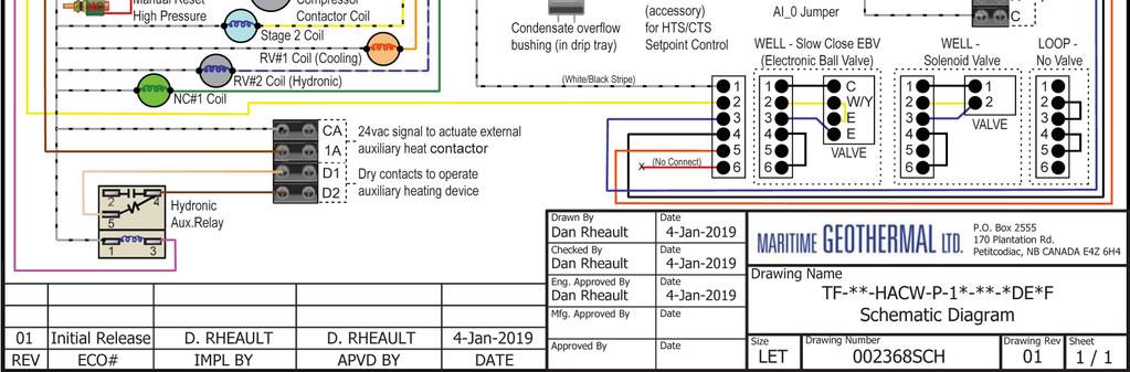
96 Wiring Diagram (208/ ) MAN-01 Page 96
 Page 97")
97 Electrical Box Layout (208/ ) Page MAN-01


98 Wiring Diagram ( ) MAN-01 Page 98
 Page 99")
99 Electrical Box Layout ( ) Page MAN-01

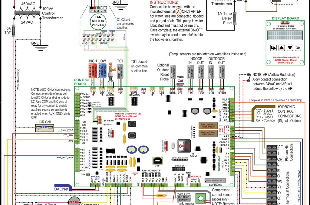
100 Wiring Diagram ( ) MAN-01 Page 100


101 Electrical Box Layout ( ) Page MAN-01
102 002362MAN-01 Page 102
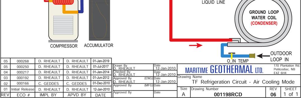
103 Page MAN-01
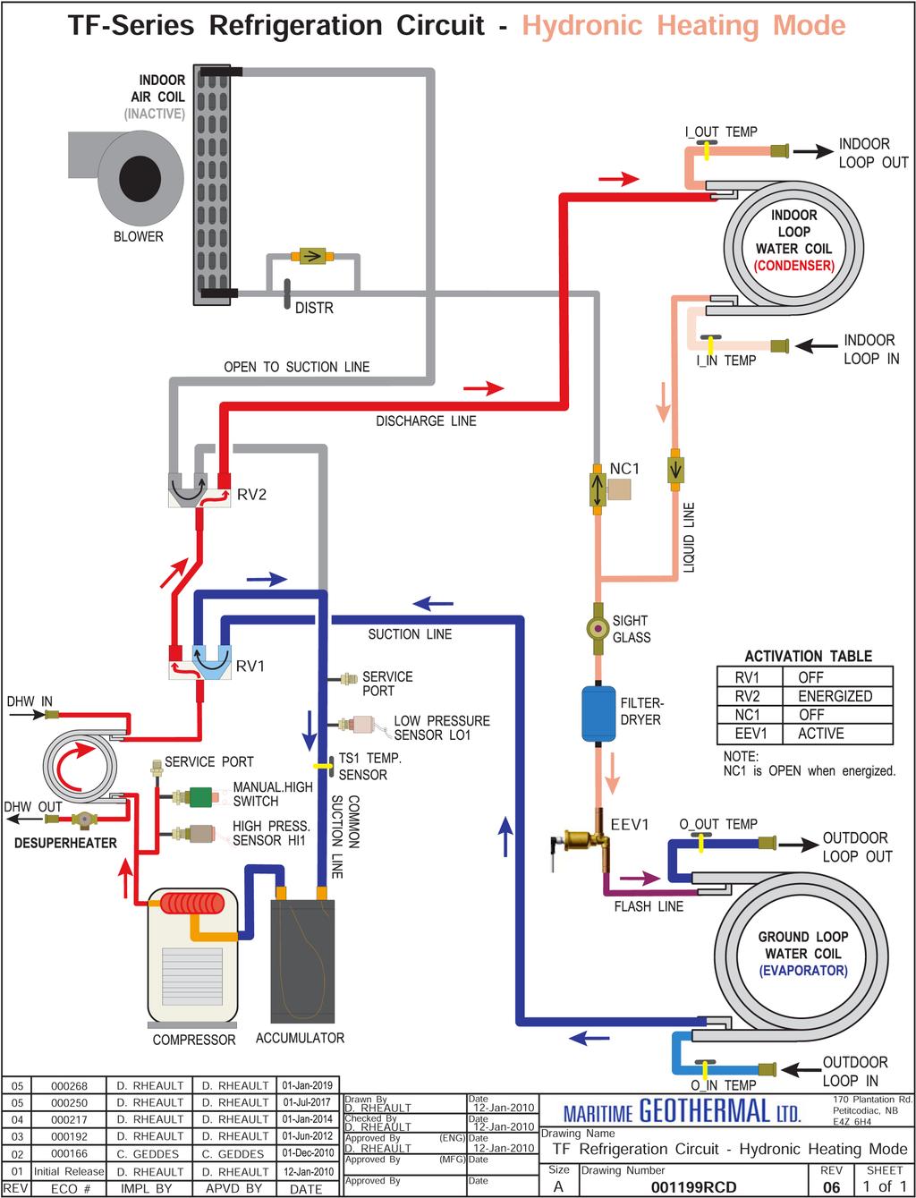
104 002362MAN-01 Page 104

105 Dimensions: TF-45 Left Return Page MAN-01
106 Dimensions: TF-45 Right Return MAN-01 Page 106


107 Dimensions: TF-55/65/75/80 Left Return Page MAN-01

108 Dimensions: TF-55/65/75/80 Right Return MAN-01 Page 108

109 Appendix A - GEN2 Control Board Description The picture below shows the locations of the connectors and LED indicators of the control board. The control board offers many features such as short circuit protection on all digital outputs, Real Time Clock with super capacitor for backup power, WiFi capability, relay outputs for plenum heater control (if equipped), USB port, PIC32 microcontroller, etc. High Pressure1 Sensor Connector Low Pressure1 Sensor Connector Suction Line1 Temperature Probe Connector Suction Line2 Temperature Probe Connector High Pressure2 Sensor Connector Low Pressure2 Sensor Connector Temperature Auto Calibration Connector High Pressure1 Fault Indicator Low Pressure1 Fault Indicator Local (Indoor) EEV1 Connector Remote (Outdoor) EEV2 Connector High Pressure2 Fault Indicator Low Pressure2 Fault Indicator Outdoor Temperature Probe Connector Temperature Connectors INDOOR OUTDOOR IN OUT IN OUT Digital Outputs Indoor Fan Connector Aquastat Connections PWM Channels (4 out 1 in) Thermostat Connections Digital Inputs Flow Switches Phase Monitors Plenum Heat Airflow Reduction BACnet MS/TP Connector Digital Outputs Heartbeat (flashes once per second) Analog Inputs AI0 to AI5 5VCD 12VDC 24VDC power indicators WiFi Connector Fault Indicator LCD Display Connector Short Circuit Protectors 24VAC Power Indicator USB Connector Power supplies for external sensors for use with Analog Inputs AI0 to AI5 MODBUS MS/TP Connector Page MAN-01
110 The tables describe the connections starting with the top of the board and working around the board counter clock-wise. TABLE A1 - Control Board Connector Descriptions (Top) Name Description HPS1/HI1 High Pressure Sensor 1 Measures discharge pressure. LPS1/LO1 Low Pressure Sensor 1 Measures suction pressure. EEV1 Local EEV Control of Electronic Expansion Valve. TS1 Suction Line Temperature 1 Mounted to common suction line inside unit. EEV2 Remote EEV Unused. TS2 Suction Line Temperature 2 Unused. HPS2/HI2 High Pressure Sensor 2 Unused. LPS2/LO2 Low Pressure Sensor 2 Unused. HTS Outdoor Temperature Optional outdoor temperature sensor for outdoor reset feature. CTS Auto Calibration Resistor in connector for auto-calibration reference (32 F 0 C). I_IN Indoor Loop IN Mounted to pipe inside unit. I_OUT Indoor Loop OUT Mounted to pipe inside unit. O_IN Outdoor Loop IN Mounted to pipe inside unit. O_OUT Outdoor Loop OUT Mounted to pipe inside unit. TABLE A2 - Control Board Connector Descriptions (Left Side) Name Description PWM_IN Signal for PWM IN Unused. IN_SPARE Spare digital input Unused. COM_IN Common for PWM IN Unused. PWM4 PWM / 0-10VDC output Unused. PWM3 PWM / 0-10VDC output Unused. PWM2 PWM / 0-10VDC output Unused. PWM1 PWM / 0-10VDC output Unused. GND Ground Unused. HZC Hot Zone Circulator Unused. CZC Cold Zone Circulator Unused. ICR Internal Circulator Relay Operates the Indoor Circulator. DO_3 Auxiliary Only Output when hydronic auxiliary to be run without compressor. DO_2 Hydronic Auxiliary Operates the hydronic auxiliary, pin 1A (Setpoint Control only). DO_1 Digital output Unused. DO_0 Digital output To open loop water valve end switch or closed loop jumper plug (back to ODFLO). LC Loop common (ground) Unused. L6 Loop6 Unused. L5 Loop5 Unused. L4 Loop4 Unused. L3 Loop3 Unused. L2 Loop2 Unused. L1 Loop1 Unused. C(SH) Soaker Hose common Unused. SH Soaker Hose Unused MAN-01 Page 110
111 TABLE A3 - Control Board Connector Descriptions (Bottom) Name Description GND BACnet MS/TP Ground for shield if required. B BACnet MS/TP RS-485. A BACnet MS/TP RS-485. STAGE1 Compressor Stage 1 Starts / stops the compressor. STAGE2 Compressor Stage 2 Turns the compressor Stage 2 solenoid on/off. RV_#1 Reversing Valve#1 Off in heating modes, on in air cooling mode. RV_#2 Reversing Valve#2 Off in air heating or cooling modes, on in water heating mode. SOL#1 Solenoid#1 Unused. SOL#2 Solenoid#2 Unused. 24VAC Power supply for board 24VAC power for control board. COM Power supply for board GND for control board. AI_5 Analog In Channel 5 Optional type 3/7 10k hot tank temperature sensor for HTS/CTS Setpoint Control. AI_4 Analog In Channel 4 0 to 5VDC or 4-20mA user settable with board jumper. AI_3 Analog In Channel 3 0 to 5VDC or 4-20mA user settable with board jumper. AI_2 Analog In Channel 2 0 to 5VDC or 4-20mA user settable with board jumper. AI_1 Analog In Channel 1 0 to 5VDC or 4-20mA user settable with board jumper. AI_0 Analog In Channel 0 Optional compressor current sensor. GND Ground pin Ground for analog sensors. GND Ground pin Ground for analog sensors. 5VDC Power for analog sensors Provides 5VDC power supply for sensors. 12VDC Power for analog sensors Provides 12VDC power supply for sensors. 24VDC Power for analog sensors Provides 24VDC power supply for sensors. A MODBUS RS-485. B MODBUS RS-485. GND MODBUS Ground for shield if required. Page MAN-01
112 TABLE A4 - Control Board Connector Descriptions (Right Side) Name Description DI_1 Digital Input1 Unused. DI_0 Digital Input0 Low pressure select from open/closed loop harness (0=open loop, 1=closed loop) PM2 Phase Monitor2 Unused. PM1 Phase Monitor1 Accessory for 3 phase models. Y2A* Aquastat Stage2 Optional water heat stage 2 24VAC input for use with Signals/Hardwired control. RA* Aquastat Power (24VAC) Optional 24VAC output for aquastat used with Signals/Hardwired control. Y1A* Aquastat Stage1 Optional water heat stage 1 24VAC input for use with Signals/Hardwired control. CA* Aquastat Power (Ground) Optional 24VAC ground for aquastat used with Signals/Hardwired control. 2 Plenum Heat Stage2 Dry contact output to activate air plenum heater stage 2. 1 Plenum Heat Stage1 Dry contact output to activate air plenum heater stage 1. C Plenum Heat Common Common terminal for air plenum heater dry contacts. AR Airflow Reductions Digital input to reduce airflow for zoning applications. 24VAC Power Power to external dry contact for AR terminal & low pressure select (DI_0). ODFLO Outdoor Flow Switch Return signal from open loop water valve end switch, or closed loop jumper plug. IDFLO Indoor Flow Switch Optional indoor loop flow switch digital input. L Thermostat Lockout Indicator 24VAC to external trouble indicator. E Thermostat Emergency Heat 24VAC input from air thermostat. O Thermostat Heat/Cool 24VAC input from air thermostat. W2 Thermostat Auxiliary Heat 24VAC input from air thermostat. Y2 Thermostat Stage2 24VAC input from air thermostat. Y1 Thermostat Stage1 24VAC input from air thermostat. G Thermostat Fan Recirculation 24VAC input from air thermostat. R Thermostat Power (24VAC) 24VAC to air thermostat. C Thermostat Power (Ground) 24VAC ground for air thermostat. *NOTE: There is no need for an external aquastat for most systems, since the Setpoint Control Method provides built in aquastat functionality MAN-01 Page 112


113 Appendix B - USB Driver Installation The first step in connecting a Windows laptop computer to the control board is to install the USB driver. 3. Choose Open with Windows Explorer, and hit OK : Any version of Windows from XP and onwards is compatible, including 7 & 10. Screenshots shown are from Windows Go to Download Software page: 4. In the window that is displayed, click and hold down the mouse button on the folder name, and drag to your desktop: 2. Click on MGL GEN2 USB Driver Installer to download it: 5. Double click on the folder you just dragged onto the desktop, then double click on the USBDriverInstaller file: 6. In the next window, click on Install Drivers : 7. You will see a message indicating the driver was installed successfully. Proceed to the PC App Installation. Page MAN-01


114 Appendix C - PC App Installation The second step in connecting a Windows laptop computer to the control board is to install the PC App. Be sure USB driver is already installed. Any version of Windows from XP and onwards is compatible, including 7 & 10. Screenshots shown are from Windows Choose Open with Windows Explorer, and hit OK : 1. Go to Download Software page: 4. In the window that is displayed, click and hold down the mouse button on the folder name, and drag to your desktop: 2. Click on MGL GEN2 PCAPP V to download it. Choose the latest version, which has the highest number and appears highest in the list. 5. Double click on the folder you just dragged onto the desktop, then double click on the setup file: 6. Click Yes, Run, Install, or similar on any warning windows which pop up. If an error message is encountered regarding Visual Basic PowerPacks or.netframework, exit the installation and use the links on the Download Software page to install the missing items: Then go back to step The PC App will open when it is finished installing. You are now ready to connect a USB cord between the laptop computer and GEN2 control board, and connect MAN-01 Page 114
.")

 cable from the PC to the control board. 4. Launch the PC APP (V1.30 or higher) and click on the Connect Button to connect to the control board. 5.")
115 Appendix D - Updating Firmware METHOD 1: Updating Firmware Using PC App The following provides step by step instructions to update the firmware in the control board to the latest release. The firmware comes as a ZIP file named: MGT GEN2 Bootload Firmware Vxxx.zip where xxx is the version reference, e.g. 254 (version 2.54, this will be used for the remainder of this procedure). This file can be downloaded from our website Menu For Dealers --> Download Software ; choose the latest (highest numbered) version. 1. Download the file to your PC; we recommend creating a folder system such as: Desktop\MGT GEN2 Bootload Firmware\V Unzip the file in the created folder. There will be three files: The firmware file: MGT_GEN2_V254.production.hex The programmer: PIC32UBL.exe Instruction sheet: USB Bootloader Instructions V2.pdf 3. Connect a USB (printer) cable from the PC to the control board. 4. Launch the PC APP (V1.30 or higher) and click on the Connect Button to connect to the control board. 5. Go to menu Tools Configuration Page (picture to right) 6. Click on the FIRMWARE UPDATE button. The following message will appear: 8. Click on OK. The following message will appear: 7. Click on YES. The following message will appear: 9. Click on OK. The control board is now in bootloader mode and is ready to be programmed. 10. Run PIC32UBL.exe. Click on the USB Enable check box. The screen should look like below. Page MAN-01


116 11. Click on Connect. The messages should read: 14. Programmed and verified. Click on Run Application. The messages should read: If device fails to connect and an error message is displayed, the board s bootloader may be older than v2.0. It will be necessary to instead update the firmware via jumper pins, as per the next section. 12. Click on Load Hex File. Select the MGT_GEN2_V254.production.hex file and click on Open. The messages should read: 15. Wait until the programmer disconnects itself. The messages should read as follows: 13. Click on Erase Program Verify. Programming. Wait while status bar shows progress. The messages should read as below when finished: 16. Close the program. 17. WAIT APPROXIMATELY 10 SECONDS. This gives the control board time to reset, initialize and re-connect to the PC USB port. 18. Go back to the PC APP and click on the Connect button. Verify that the firmware version has been updated. Perform any configuration needed. IMPORTANT NOTE: updating the firmware does not affect the configuration settings MAN-01 Page 116


117 METHOD 2: Updating Firmware Using Jumper Pins The following provides step by step instructions to update the firmware in the control board to the latest release. 6. Turn the power back on. The control board is now in boot loader mode and is ready to be programmed. The firmware comes as a ZIP file named: MGT GEN2 Bootload Firmware Vxxx.zip where xxx is the version reference, i.e. 255 (version 2.55, this will be used for the remainder of this procedure). This file can be downloaded from our website There is a table which lists the latest firmware by heat pump series, select the appropriate file to download. 7. Run PIC32UBL.exe. Click on the USB Enable check box. The screen should look like the picture below. 1. Download the file to your PC, we recommend creating a folder system such as the following: Desktop\MGT GEN2 Bootload Firmware\V Unzip the file in the created folder. There will be two files: The firmware file: MGT_GEN2_V255.production.hex The programmer: PIC32UBL.exe 3. Connect a USB cable to the control board. 4. Turn the power off to the unit. 5. Remove one of the black pin jumpers from just below the USB connector on the board and place in on the center pin pair of the EXPANSION header as shown below. 8. Click on Connect. Remove a jumper from here. 9. Click on Load Hex File. Select the MGT_GEN2_V255.prod uction.hex file. 10. Click on Erase Program Verify Programming Place jumper here. 11. Programming completed. Verification successful. Click on Disconnect and close the program. 12. Turn the power off. 13. Move the jumper back to where it was taken from. 14. Turn the power back on. Check that the LCD Display shows MGT GEN2 V2.55 on the top line. Page MAN-01
 or its representatives, relating to MG s products, whether oral, written or contained in any sales literature, catalogue or agreement, are")

118 LIMITED EXPRESS WARRANTY It is expressly understood that unless a statement is specifically identified as a warranty, statements made by Maritime Geothermal Ltd., a corporation registered in New Brunswick, Canada, ( MG ) or its representatives, relating to MG s products, whether oral, written or contained in any sales literature, catalogue or agreement, are not express warranties and do not form a part of the basis of the bargain, but are merely MG s opinion or commendation of MG s products. EXCEPT AS SPECIFICALLY SET FORTH HEREIN, THERE IS NO EXPRESS WARRANTY AS TO ANY OF MG S PRODUCTS. MG MAKES NO WARRANTY AGAINST LATENT DEFECTS. MG MAKES NO WARRANTY OF MERCHANTABILITY OF THE GOODS OR OF THE FITNESS OF THE GOODS FOR ANY PARTICULAR PURPOSE. LIMITED EXPRESS RESIDENTIAL WARRANTY - PARTS MG warrants its Residential Class products, purchased and retained in the United States of America and Canada, to be free from defects in material and workmanship under normal use and maintenance as follows: (1) Air conditioning, heating and/or heat pump units built or sold by MG ( MG Units ) for five (5) years from the Warranty Inception Date (as defined below). (2) Thermostats, auxiliary electric heaters and geothermal pumping modules built or sold by MG, when installed with MG Units, for five (5) years from the Warranty Inception Date (as defined below). (3) Sealed refrigerant circuit components of MG Units (which components only include the compressor, refrigerant to air/water heat exchangers, reversing valve body and refrigerant metering device) for ten (10) years from the Warranty Inception Date (as defined below). (4) Other accessories and parts built or sold by MG, when installed and purchased with MG Units, for five (5) years from the date of shipment from MG. (5) Other accessories, when purchased separately, for (1) year from the date of shipment from MG. The Warranty Inception Date shall be the date of original unit installation, as per the date on the installation Startup Record or six (6) months from date of unit shipment from MG, whichever comes first. To make a claim under this warranty, parts must be returned to MG in Petitcodiac, New Brunswick, freight prepaid, no later than ninety (90) days after the date of the failure of the part. If MG determines the part to be defective and within MG s Limited Express Residential Warranty, MG shall, when such part has been either replaced or repaired, return such to a factory recognized distributor, dealer or service organization, freight prepaid. The warranty on any part repaired or replaced under warranty expires at the end of the original warranty period. LIMITED EXPRESS RESIDENTIAL WARRANTY - LABOUR This Limited Express Residential Labour Warranty shall cover the labour incurred by MG authorized service personnel in connection with the installation of a new or repaired warranty part that is covered by this Limited Express Residential Warranty only to the extent specifically set forth in the current labour allowance schedule "A" provided by MG s Warranty Department and only as follows: (1) MG Units for two (2) years from the Warranty Inception Date. (2) Thermostats, auxiliary electric heaters and geothermal pump modules built or sold by MG, when installed with MG Units, for two (2) years from the Warranty Inception Date. (3) Sealed refrigerant circuit components of MG Units (which components only include the compressor, refrigerant to air/water heat exchangers, reversing valve body and refrigerant metering device) for five (5) years from the Warranty Inception Date. Labour costs are not covered by this Limited Express Residential Warranty to the extent they exceed the amount allowed under said allowance schedule, they are not specifically provided for in said allowance schedule, they are not the result of work performed by MG authorized service personnel, they are incurred in connection with a part not covered by this Limited Express Residential Warranty, or they are incurred more than the time periods set forth in this paragraph after the Warranty Inception Date. This warranty does not cover and does not apply to: (1) Air filters, fuses, refrigerant, fluids, oil. (2) Products relocated after initial installation. (3) Any portion or component of any system that is not supplied by MG, regardless of the cause of the failure of such portion or component. (4) Products on which the unit identification tags or labels have been removed or defaced. (5) Products on which payment to MG, or to the owner s seller or installing contractor, is in default. (6) Products subjected to improper or inadequate installation, maintenance, repair, wiring or voltage conditions. (7) Products subjected to accident, misuse, negligence, abuse, fire, flood, lightning, unauthorized alteration, misapplication, contaminated or corrosive liquid or air supply, operation at abnormal air or liquid temperatures or flow rates, or opening of the refrigerant circuit by unqualified personnel. (8) Mold, fungus or bacteria damage (9) Corrosion or abrasion of the product. (10) Products supplied by others. (11) Products which have been operated in a manner contrary to MG s printed instructions. (12) Products which have insufficient performance as a result of improper system design or improper application, installation, or use of MG s products. (13) Electricity or fuel, or any increases or unrealized savings in same, for any reason whatsoever. Except for the limited labour allowance coverage set forth above, MG is not responsible for: (1) The costs of fluids, refrigerant or system components supplied by others, or associated labour to repair or replace the same, which is incurred as a result of a defective part covered by MG s Limited Residential Warranty. (2) The costs of labour, refrigerant, materials or service incurred in diagnosis and removal of the defective part, or in obtaining and replacing the new or repaired part. (3) Transportation costs of the defective part from the installation site to MG, or of the return of that part if not covered by MG s Limited Express Residential Warranty. (4) The costs of normal maintenance. This Limited Express Residential Warranty applies to MG Residential Class products manufactured on or after February 15, MG S LIABILITY UNDER THE TERMS OF THIS LIMITED WARRANTY SHALL APPLY ONLY TO THE MG UNITS REGISTERED WITH MG THAT BEARS THE MODEL AND SERIAL NUMBERS STATED ON THE INSTALLATION START UP RECORD, AND MG SHALL NOT, IN ANY EVENT, BE LIABLE UNDER THE TERMS OF THIS LIMITED WARRANTY UNLESS THIS INSTALLATION START UP RECORD HAS BEEN ENDORSED BY OWNER & DEALER/INSTALLER AND RECIEVED BY MG LIMITED WITHIN 90 DAYS OF START UP. Limitation: This Limited Express Residential Warranty is given in lieu of all other warranties. If, not withstanding the disclaimers contained herein, it is determined that other warranties exist, any such express warranty, including without imitation any express warranties or any implied warranties of fitness for particular purpose and merchantability, shall be limited to the duration of the Limited Express Residential Warranty. LIMITATION OF REMEDIES In the event of a breach of the Limited Express Residential Warranty, MG will only be obligated at MG s option to repair the failed part or unit, or to furnish a new or rebuilt part or unit in exchange for the part or unit which has failed. If after written notice to MG s factory in Petitcodiac, New Brunswick of each defect, mal-function or other failure, and a reasonable number of attempts by MG to correct the defect, malfunction or other failure, and the remedy fails of its essential purpose, MG shall refund the purchase price paid to MG in exchange for the return of the sold good(s). Said refund shall be the maximum liability of MG. THIS REMEDY IS THE SOLE AND EXCLUSIVE REMEDY OF THE BUYER OR PURCHASER AGAINST MG FOR BREACH OF CONTRACT, FOR THE BREACH OF ANY WARRANTY OR FOR MG S NEGLIGENCE OR IN STRICT LIABILITY. LIMITATION OF LIABILITY MG shall have no liability for any damages if MG s performance is delayed for any reason or is prevented to any extent by any event such as, but not limited to: any war, civil unrest, government restrictions or restraints, strikes, or work stoppages, fire, flood, accident, shortages of transportation, fuel, material, or labour, acts of God or any other reason beyond the sole control of MG. MG EXPRESSLY DISCLAIMS AND EXCLUDES ANY LIABILITY FOR CONSEQUENTIAL OR INCIDENTAL DAMAGE IN CONTRACT, FOR BREACH OF ANY EXPRESS OR IMPLIED WARRANTY, OR IN TORT, WHETHER FOR MG s NEGLIGENCE OR AS STRICT LIABILITY. OBTAINING WARRANTY PERFORMANCE Normally, the dealer or service organization who installed the products will provide warranty performance for the owner. Should the installer be unavailable, contact any MG recognized distributor, dealer or service organization. If assistance is required in obtaining warranty performance, write or call: Maritime Geothermal Ltd Customer Service PO Box 2555 Petitcodiac, New Brunswick E4Z 6H4 (506) or to info@nordicghp.com NOTE: Some states or Canadian provinces do not allow limitations on how long an implied warranty lasts, or the limitation or exclusions of consequential or incidental damages, so the foregoing exclusions and limitations may not apply to you. This warranty gives you specific legal rights, and you may also have other rights which vary from state to state and from Canadian province to Canadian province. Please refer to the MG Installation, Installation and Service Manual for operating and maintenance instructions MAN-01 Page 118
Installation and Service Manual
 Installation and Service Manual W-Series Liquid to Water Geothermal Heat Pump Two-Stage R410a Model Sizes 25-80 Maritime Geothermal Ltd. P.O. Box 2555 Petitcodiac, NB E4Z 6H4 (506) 756-8135 Email: info@nordicghp.com
Installation and Service Manual. Hydronic Geothermal Heat Pumps
 Installation and Service Manual Boreal W-Series (HW) Model Size 100 (9 Ton) R410a Hydronic Geothermal Heat Pumps Boreal Geothermal Inc. Phone : 450-534-0203 Fax : 450-534-1864 Email: info@boreal-geothermal.com
Installation and Service Manual
 Installation and Service Manual ATW-Series Reversing Air to Water Heat Pump Two-Stage R410a Model Sizes 25-75 Maritime Geothermal Ltd. P.O. Box 2555, 170 Plantation Road Petitcodiac, NB E4Z 6H4 (506) 756-8135
Installation and Service Manual
 Installation and Service Manual RS-Series Modular Design Split System Compressor Unit Two-Stage R410a Model Sizes 25-75 Liquid to Air Split System Compressor Unit Maritime Geothermal Ltd. P.O. Box 2555
Installation and Service Manual
 Installation and Service Manual WD-Series Wall Mounted Domestic Hot Water Water-Source Heat Pump R134a 60Hz Maritime Geothermal Ltd. P.O. Box 2555, 170 Plantation Road Petitcodiac, NB E4Z 6H4 (506) 756-8135
ENGINEERING SPECIFICATIONS
 ENGINEERING SPECIFICATIONS RH-24-HAC-P-1L-C-SDE*F Horizontal Single Stage R410a Model Size 24 Reversing (Heating AND Cooling) 208/230-1-60VAC Liquid to Air Geothermal Heat Pumps Maritime Geothermal Ltd.
ENGINEERING SPECIFICATIONS
 ENGINEERING SPECIFICATIONS RH-12-HAC-P-1L-C-SDE*F Horizontal Single Stage R410a Model Size 12 Reversing (Heating AND Cooling) 208/230-1-60VAC Liquid to Air Geothermal Heat Pumps Maritime Geothermal Ltd.
Installation and Service Manual. In-Floor Warming Module external desuperheater for 3rd party air source heat pumps
 Installation and Service Manual IFM-Series In-Floor Warming Module Model Size 48 In-Floor Warming Module external desuperheater for 3rd party air source heat pumps Maritime Geothermal Ltd. P.O. Box 2555
Installation and Service Manual. Heat Recovery Pool Conditioners
 Installation and Service Manual PC-Series Scroll R410a Model Sizes 45-80 Heat Recovery Pool Conditioners Maritime Geothermal Ltd. P.O. Box 2555 Petitcodiac, N.B. E4Z 6H4 Ph. (506)756-8135 Email: info@nordicghp.com
PRE-ASSEMBLED RADIANT CONTROL PANEL INSTALLATION MANUAL
 FloorHeat PRE-ASSEMBLED RADIANT CONTROL PANEL INSTALLATION MANUAL Thank you for purchasing this radiant control panel assembly. Following are some important notes that will make the installation successful.
Engineering Specification
 Engineering Specification WC-55-H-C-*D-** High Temperature Cascade Water to Water Heat Pump 60 Hz Maritime Geothermal Ltd. P.O. Box 2555, 170 Plantation Road Petitcodiac, NB E4Z 6H4 (506) 756-8135 info@nordicghp.com
Engineering Specification
 Engineering Specification WH-55-H-B-*S-** High Temperature Water to Water Heat Pump 60 Hz Maritime Geothermal Ltd. P.O. Box 2555, 170 Plantation Road Petitcodiac, NB E4Z 6H4 (506) 756-8135 info@nordicghp.com
Engineering Specification
 Engineering Specification WH-85-H-B-*S-PD High Temperature Water to DHW Heat Pump 60 Hz Maritime Geothermal Ltd. P.O. Box 2555, 170 Plantation Road Petitcodiac, NB E4Z 6H4 (506) 756-8135 info@nordicghp.com
ENGINEERING SPECIFICATIONS
 ENGINEERING SPECIFICATIONS W-75-HACW-P-1T-** Liquid to Water Geothermal Heat Pump Two-Stage R410a 208/230-1-60 Maritime Geothermal Ltd. P.O. Box 2555 Petitcodiac, NB E4Z 6H4 (506)756-8135 Email: info@nordicghp.com
INSTALLATION MANUAL GEO-BOOST GROUND LOOP HEAT EXCHANGER
 1103 N HIGH CROSS RD URBANA, IL 61802 1-773-492-1893 INSTALLATION MANUAL GEO-BOOST GROUND LOOP HEAT EXCHANGER REV 1.0 The Geo-Boost system consists of the Geo-Boost heat exchanger and a relay controller
Operation Manual SCT14B and SCT18B. Inspection. 3 General Description. 3 General Requirements. 3 Standard Features.
 Spot Cooling Systems, Inc. 120 Century Drive Suite 00 Carrollton, TX 7006 00-6-776 Operation Manual SCT1B and SCT1B Warning! Improper installation, adjustment, alteration, service, or maintenance can cause
INSTALLATION INSTRUCTIONS GEO PRIME TANK. (Patent Pending) GPC
 GPC") INSTALLATION INSTRUCTIONS GEO PRIME TANK (Patent Pending) GPC Table of Contents General Description 2 Installation 3 Flushing and Purging 5 Initial Start up 7 Adding or Checking Fluid 8 Replacing a Pump
INSTALLATION INSTRUCTIONS GEO PRIME TANK (Patent Pending) GPC Table of Contents General Description 2 Installation 3 Flushing and Purging 5 Initial Start up 7 Adding or Checking Fluid 8 Replacing a Pump
Engineering Specification
 Engineering Specification ATW-25-HACW-P-*T-* Air to Water Heat Pump 60 Hz Maritime Geothermal Ltd. P.O. Box 2555, 170 Plantation Road Petitcodiac, NB E4Z 6H4 (506) 756-8135 info@nordicghp.com www.nordicghp.com
INSTALLATION MANUAL GEO-BOOST GROUND LOOP HEAT EXCHANGER
 INSTALLATION MANUAL GEO-BOOST GROUND LOOP HEAT EXCHANGER Build Equinox support@buildequinox.com (773)-492-1893 Rev 2.0-05/10/2018 Build Equinox 2018 The Geo-Boost system consists of the Geo-Boost heat
Installation, Operating, and Maintenance Manual
 www.geo-flo.com Engineered Solutions Making Geothermal Easier Installation, Operating, and Maintenance Manual Part # 3619 Rev. 27APR2017 Geo-Booster Geo-Flo Products Corporation 905 Williams Park Drive
Engineering Specification
 Engineering Specification W-55-HACW-P-1T-** Liquid to Water Geothermal Heat Pump 60 Hz Maritime Geothermal Ltd. P.O. Box 2555, 170 Plantation Road Petitcodiac, NB E4Z 6H4 (506) 756-8135 info@nordicghp.com
Engineering Specification
 Engineering Specification W-25-HACW-P-1T-** Liquid to Water Geothermal Heat Pump 60 Hz Maritime Geothermal Ltd. P.O. Box 2555, 170 Plantation Road Petitcodiac, NB E4Z 6H4 (506) 756-8135 info@nordicghp.com
Engineering Specification
 Engineering Specification W-75-HACW-P-1T-** Liquid to Water Geothermal Heat Pump 60 Hz Maritime Geothermal Ltd. P.O. Box 2555, 170 Plantation Road Petitcodiac, NB E4Z 6H4 (506) 756-8135 info@nordicghp.com
ENGINEERING SPECIFICATIONS
 ENGINEERING SPECIFICATIONS W-150-H-P-*D-PP Vertical Dual Refrigeration Circuit Scroll Compressors R410a Refrigerant Nominal Size 12 Ton Non-Reversing (Heating OR Cooling) Commercial Hydronic Geothermal
Combo Geothermal Heat Pump
 Combo Geothermal Heat Pump Installation & Operating Instructions Model: RU-VE* Application Geo source, loop or ground water fluid Forced air vertical cabinet output Standard left ducting return, easily
Engineering Specification
 Engineering Specification R-55-HACW-P-*T-*-SDE*F Liquid to Air Geothermal Heat Pump 60 Hz Maritime Geothermal Ltd. P.O. Box 2555, 170 Plantation Road Petitcodiac, NB E4Z 6H4 (506) 756-8135 info@nordicghp.com
Engineering Specification
 Engineering Specification R-65-HACW-P-*T-*-SDE*F Liquid to Air Geothermal Heat Pump 60 Hz Maritime Geothermal Ltd. P.O. Box 2555, 170 Plantation Road Petitcodiac, NB E4Z 6H4 (506) 756-8135 info@nordicghp.com
EarthLinked SW Series Compressor Unit R-410A Quik-Start Instructions
 EarthLinked SW Series Compressor Unit R-410A Quik-Start Instructions CONTENTS PAGE Pre-Installation 3 Placement & Mechanical Information 4 System Application Options 10 Antifreeze Protection 14 Electrical
DOUBLE O-RING GEO-PRIME TANK Non-Pressurized Flow Center System INSTALLATION INSTRUCTIONS. Model: DORGPT-1 NOTE:
 INSTALLATION INSTRUCTIONS DOUBLE O-RING GEO-PRIME TANK Non-Pressurized Flow Center System Model: DORGPT-1 NOTE: This guide provides the installer with instructions specific to the Bard Double O-Ring Geo-Prime
Engineering Specification
 Engineering Specification R-55-HACW-P-*T-*-SDE*F Liquid to Air Geothermal Heat Pump 60 Hz Maritime Geothermal Ltd. P.O. Box 2555, 170 Plantation Road Petitcodiac, NB E4Z 6H4 (506) 756-8135 info@nordicghp.com
CROWN. Boiler Co. Santa-Fe Series. Hydronic Air Handlers INSTALLATION, OPERATION & MAINTENANCE INSTRUCTIONS
 CROWN Boiler Co Santa-Fe Series Hydronic Air Handlers INSTALLATION, OPERATION & MAINTENANCE INSTRUCTIONS These instructions must be affixed on or adjacent to the air handler Models: SAC049A20 SAC059A25
Engineering Specification
 Engineering Specification W-150-H-P-*D-PP Commercial Water to Water Heat Pump Dual Refrigeration Circuit, R410a Nominal Size 12 Ton Non-Reversing Maritime Geothermal Ltd. P.O. Box 2555, 170 Plantation
Technical Development Program COMMERCIAL HVAC SYSTEMS. Water Source Heat Pump Systems PRESENTED BY: Ray Chow. Sales Engineer
 Technical Development Program PRESENTED BY: COMMERCIAL HVAC SYSTEMS Water Source Heat Pump Systems Ray Chow Sales Engineer TDP Updates Menu Section 1 Section 2 Section 3 Section 4 Section 5 Section 6 Section
MHNCCX DX with Hot Water Heat Ceiling Concealed 4-Pipe Heat / Cool Fan Coil 12,000-36,000 BTUH
 MHNCCX DX with Hot Water Heat Ceiling Concealed 4-Pipe Heat / Cool Fan Coil 12,000-36,000 BTUH 318 MHNCCX NOMENCLATURE BREAKDOWN 4-Pipe Heat/Cool Ceiling Concealed Fan Coil MHNCCW- XX - XX Ceiling Concealed
G Series. G Series Air Coils Installation ti Manual ENCASED/UNCASED AIR COILS. Geothermal/Water Source Heat Pumps R-410A Refrigerant 2-5 Ton
 G Series ENCASED/UNCASED AIR COILS Geothermal/Water Source Heat Pumps R-410A Refrigerant 2- Ton Dimensional Data G Series Air Coils Installation ti Manual Installation Information Maintenance IM1018AG1
EarthLinked HC Series Compressor Unit R-410A Quik-Start Instructions
 EarthLinked HC Series Compressor Unit R-410A Quik-Start Instructions CONTENTS PAGE Pre-Installation 3 Placement & Mechanical Information 4 System Application Options 11 Antifreeze Protection 14 Electrical
Engineering Specification
 Engineering Specification W-185-H-P-*D-PP Commercial Water to Water Heat Pump Dual Refrigeration Circuit, R410a Nominal Size 17 Ton Non-Reversing Maritime Geothermal Ltd. P.O. Box 2555, 170 Plantation
Engineering Specification
 Engineering Specification W-600-H-P-*D-PP Commercial Water to Water Heat Pump Dual Refrigeration Circuit, R410a Nominal Size 50 Ton Non-Reversing Maritime Geothermal Ltd. P.O. Box 2555, 170 Plantation
Engineering Specification
 Engineering Specification WH-150-H-B-*D-PP High Temperature Water to Water Heat Pump 60 Hz Maritime Geothermal Ltd. P.O. Box 2555, 170 Plantation Road Petitcodiac, NB E4Z 6H4 (506) 756-8135 info@nordicghp.com
Engineering Specification
 Engineering Specification WH-400-H-B-*D-PP High Temperature Water to Water Heat Pump 60 Hz Maritime Geothermal Ltd. P.O. Box 2555, 170 Plantation Road Petitcodiac, NB E4Z 6H4 (506) 756-8135 info@nordicghp.com
Engineering Specification
 Engineering Specification ATW-45-HACW-P-*T-* Air to Water Heat Pump 60 Hz Maritime Geothermal Ltd. P.O. Box 2555, 170 Plantation Road Petitcodiac, NB E4Z 6H4 (506) 756-8135 info@nordicghp.com www.nordicghp.com
RV Products Division INSTALLATION INSTRUCTIONS FOR SERIES PACKAGE AIR CONDITIONER
 RV Products Division INSTALLATION INSTRUCTIONS FOR 46413 SERIES PACKAGE AIR CONDITIONER 1. WARNINGS IMPORTANT NOTICE These instructions are for the use of qualified individuals specially trained and experienced
Engineering Specification
 Engineering Specification ATW-65-HACW-P-*T-* Air to Water Heat Pump 60 Hz Maritime Geothermal Ltd. P.O. Box 2555, 170 Plantation Road Petitcodiac, NB E4Z 6H4 (506) 756-8135 info@nordicghp.com www.nordicghp.com
GUIDE SPECIFICATIONS AQUARIUS ii
 Catalog (AP Technical Data Sheet) GUIDE SPECIFICATIONS AQUARIUS ii AP Series Two Stage R-410A GENERAL Units shall be performance certified to ISO standard 13256-1 for Water Loop Heat Pump, Ground Water
Installation and Operation Manual
 Installation and Operation Manual WT MODELS WATER-TO-WATER HEAT PUMPS REVISION C 20D218-09NN 20D218-09NN Section 1: WT Water-To-Water Unit Model Nomenclature Unit Model Nomenclature... 3 Section 2: Installation
AHG**-0B Series Hydronic Air Handling Units
 HEAT CONTROLLER, INC. Installation, Operation and Maintenance Manual Installation, Operation and Maintenance Manual AHG**-0B Series Hydronic Air Handling Units HEAT CONTROLLER, INC. 1900 Wellworth Ave.,
OWNER S MANUAL. Vintage Classic HEAT COOL models. Proudly Made in the USA
 OWNER S MANUAL Vintage Classic HEAT COOL models Proudly Made in the USA support@aquacomfort.com www.aquacomfort.com/service-and-support 888-475-7443 Manufacturing High Quality, High Efficiency Heat Pump
B. Unit construction shall comply with ASHRAE 15 Safety Code, NEC, and ASME applicable codes (U.S.A. codes).
.") Guide Specifications PART 1 GENERAL 1.01 SYSTEM DESCRIPTION Microprocessor controlled, air-cooled liquid chiller utilizing scroll compressors, low sound fans, hydronic pump system and optional fluid storage
Guide Specifications PART 1 GENERAL 1.01 SYSTEM DESCRIPTION Microprocessor controlled, air-cooled liquid chiller utilizing scroll compressors, low sound fans, hydronic pump system and optional fluid storage
WMHP Series R410a Heat Pump INSTALLATION INSTRUCTIONS
 WMHP Series R410a Heat Pump INSTALLATION INSTRUCTIONS **WARNING TO INSTALLER, SERVICE PERSONNEL AND OWNER** Altering the product or replacing parts with non authorized factory parts voids all warranty
Installation & Operation Manual Models: TSU
 TSU-I-O Rev A Installation & Operation Manual Models: TSU 150-940 CAUTION: This appliance is not intended for potable water. This manual must only be used by a qualified heating installer / service technician.
4201 Lien Rd Madison, WI Owner s Manual Therma-Stor III Heat Recovery System. Installation, Operation & Service Instructions
 4201 Lien Rd Madison, WI 53704 TS-140F Revised 09-10 Owner s Manual Therma-Stor III Heat Recovery System Installation, Operation & Service Instructions Read and Save These Instructions Table Of Contents
Installation & Operation Manual Forced Air
 Installation & Operation Manual Forced Air Installation & Operation Manual Engineering Specifications ECONAR ColdClimate Series Forced Air Models REC-V036 REC-V060 Table of Contents I. Key & Legend...
Owner s Manual Therma-Stor II Heat Recovery System
 PO Box 8680 Madison, WI 53708 TS-138C Revised 8/08 Owner s Manual Therma-Stor II Heat Recovery System Installation, Operation & Service Instructions Read and Save These Instructions Table Of Contents 1.
EarthLinked SCW Series Compressor Unit R-410A Quik-Start Instructions
 EarthLinked SCW Series Compressor Unit R-410A Quik-Start Instructions CONTENTS PAGE Pre-Installation 3 Placement & Mechanical Information 6 System Application Options 12 Antifreeze Protection 13 Electrical
CHILLER. Operator s & Installation Manual
 CHILLER MODELS: CH1001-A Operator s & Installation Manual Release Date: August 9, 2002 Publication Number: 620914301 Revision Date: May 6, 2010 Revision: E Visit the IMI Cornelius web site at www.cornelius.com
GTIP60 ISO GT Series, Inch Pounds - 60 Hz GT (iso) Spec Guide Drawings Spec Sheets Low Temp Heating P/T Charts
 Spec Guide Drawings Spec Sheets Low Temp Heating P/T Charts") GTIP60 ISO GT Series, Inch Pounds 60 Hz GT010070 (iso) Spec Guide Drawings Spec Sheets Low Temp Heating P/T Charts Rev: 903 Rev 1 Revisions: 31103 Changed HZ dwg to field convertible 5902 changed Unit
GTIP60 ISO GT Series, Inch Pounds 60 Hz GT010070 (iso) Spec Guide Drawings Spec Sheets Low Temp Heating P/T Charts Rev: 903 Rev 1 Revisions: 31103 Changed HZ dwg to field convertible 5902 changed Unit
GUIDE SPECIFICATIONS AQUARIUS ii
 Catalog (AP Technical Data Sheet) GUIDE SPECIFICATIONS AQUARIUS ii AP Series Two Stage R-410A GENERAL Units shall be performance certified to ISO standard 13256-1 for Water Loop Pump, Ground Water Pump
Single and Two-Stage Packaged Geothermal Heat Pump
 Single and Two-Stage Packaged Geothermal Heat Pump Installation & Operating Instructions Models: TVA/TVT-*** Application Forced air Geo source installation Equipped for optional AUX EL strip heat (controller
Engineering Specification
 Engineering Specification W-300-HAC-P-*D-PP Commercial Water to Water Heat Pump Dual Refrigeration Circuit, R410a Nominal Size 23 Ton Reversing (Heating or Cooling) Maritime Geothermal Ltd. P.O. Box 2555,
EarthLinked SC Series Compressor Unit R-407C Quik-Start Instructions
 EarthLinked SC Series Compressor Unit R-407C Quik-Start Instructions CONTENTS PAGE Pre-Installation 3 Placement & Mechanical Information 4 System Application Options 11 Desuperheater Kit 15 Antifreeze
INSTALLATION INSTRUCTIONS
 INSTALLATION INSTRUCTIONS FOR AQUECOIL HYDRONIC HEATING UNITS GENERAL INFORMATION The AQUECOIL Hydronic Heating Unit is offered in many different capacities and physical configurations in order to match
3 TON Heating Performance Data TON Cooling Performance Data TON Heating Performance Data TON Cooling Performance Data...
 Table of Contents I. Key & Legend... 4 Key to Model Numbers... 4 Legend for Tables... 4 II. Warnings & Cautions... 5 III. General Information... 5 Inspection... 5 Storage 5 Protection... 5 Pre- Installation
Daikin Water Cooling, Heating, and High Capacity Booster Coils
 Installation and Maintenance Manual IM 900 Daikin Water Cooling, Heating, and High Capacity Booster Coils Group: Applied Air Part Number: IM 900 Date: February 2008 Types HI-F5, E-F5 2008 Daikin International
Agent - Manufacturer of Boreal geothermal heat pumps
 Agent - Manufacturer of Boreal geothermal heat pumps The ground source heat pump system is most advantageous heating and air-conditioning system available: economical, clean and environmental! Economical:
Condensing Unit Installation and Operating Instructions
 Bulletin WCU_O&I 01 June 2003 Condensing Unit Installation and Operating Instructions WCU Air Cooled Condensing Unit Table of Contents Section 1. Section 2. Section 3. Section 4. Section 5. Section 6.
OWNER S MANUAL. Models: AC110, AC125, AC150 made from 2003 through Proudly Made in the USA
 OWNER S MANUAL Models: AC110, AC125, AC150 made from 2003 through 2010 Proudly Made in the USA support@aquacomfort.com www.aquacomfort.com/service-and-support/ (888) 475-7443 Manufacturing High Quality,
OWNER S MANUAL. Vintage Signature Series models: AC750, AC1050, AC1100, AC1250, AC1500, AC1750. Proudly Made in the USA.
 OWNER S MANUAL Vintage Signature Series models: AC750, AC1050, AC1100, AC1250, AC1500, AC1750 Proudly Made in the USA support@aquacomfort.com 888-475-7443 Manufacturing High Quality, High Efficiency Heat
RetroAire Model Number: 9,000 to 36,000 Btuh (2.6 to 10.5 kw)
") Indoor Single Package Vertical, Air-Cooled Heat Pump Unit RetroAire Model Number: Capacity Range: VPRH 9,000 to 36,000 Btuh (2.6 to 10.5 kw) Part 1 General 1.01 UNIT DESCRIPTION A. Indoor, single package
Indoor Single Package Vertical, Air-Cooled Heat Pump Unit RetroAire Model Number: Capacity Range: VPRH 9,000 to 36,000 Btuh (2.6 to 10.5 kw) Part 1 General 1.01 UNIT DESCRIPTION A. Indoor, single package
Engineering Data and Installation Manual
 Engineering Data and Installation Manual YT MODELS PACKAGED WATER-TO-AIR MULTI-POSITIONAL HEAT PUMPS REVISION:A 20D082-10NN 20D082-10NN Table of Contents Section 1: Model Nomenclature Model Nomenclature...4
EarthLinked AVN Series Air Handlers Installation Manual
 EarthLinked AVN Series Air Handlers Installation Manual AVN-410-IM (03/14) Copyright 2014 Earthlinked Technologies, Inc. Table of Contents Model Nomenclature... 4 Safety... 5 Equipment Manuals... 5 Installation...
INSTALLATION INSTRUCTIONS TXV Horizontal Duct Coils EHD
 TXV Horizontal Duct s EHD These instructions must be read and understood completely before attempting installation. It is important that the Blower and Duct System be properly sized to allow the system
Water to Water Geothermal Heat Pump
 Water to Water Geothermal Heat Pump Installation & Operating Instructions Model: THA/THT-*** Application Geo source closed loop or ground water Hydronic water heat/cool output Air handler, water coil,
ECO1ZN3P, ECO2ZN4P ECO
 WARNING HOT This product may have hot fluid circulating through it. DO NOT TOUCH! SOME UNION NUTS MAY BECOME LOOSE AND CONSEQUENTLY LEAK THROUGH TRANSPORTATION VIBRATION AND HANDLING. DO NOT OVERTIGHTEN
Greensource Residential Water Source Heat Pumps. Simply Smart. i Series: SV Model. boschheatingandcooling.com
 Greensource Residential Water Source Heat Pumps i Series: SV Model Simply Smart The i Series SV Model is a cost-effective single stage water source heat pump that is designed for commercial retrofit and
EarthLinked CC Series Compressor Unit R-410A Quik-Start Instructions
 EarthLinked CC Series Compressor Unit R-410A Quik-Start Instructions CONTENTS PAGE Pre-Installation 3 Placement & Mechanical Information 4 System Application Options 11 Desuperheater Kit 15 Anti-Freeze
INSTALLATION INSTRUCTIONS TXV Coils for Manufactured Housing EMA
 TXV Coils for Manufactured Housing EMA NOTE: Read the entire instruction manual before starting the installation. SAFETY CONSIDERATIONS Improper installation, adjustment, alteration, service, maintenance,
Installation & Operation Manual Hydronic
 Installation & Operation Manual Hydronic Installation & Operation Manual Engineering Specifications GeoSource Hydronic Models RGS-W036 RGS-W120 This Page Intentionally Left Blank Table of Contents I. Key
INSTALLATION INSTRUCTIONS FOR 6532 SERIES PACKAGE HEAT PUMP
 INSTALLATION INSTRUCTIONS FOR 6532 SERIES PACKAGE HEAT PUMP RV Products A Division of Airxcel, Inc. P.O. Box 4020 Wichita, KS 67204 1976-360 (1-02) PP TABLE OF CONTENTS 1. Warnings......................................................
EarthLinked AFN Series Air Handlers Installation Manual
 EarthLinked AFN Series Air Handlers Installation Manual AFN-410-IM (07/15) Copyright 2015 Earthlinked Technologies, Inc. Table of Contents Model Nomenclature... 4 Safety... 5 Equipment Manuals... 5 Installation...
SPX SERIES PACKAGED AIR CONDITIONING/HEAT PUMP UNITS INSTALLATION, OPERATION AND MAINTENANCE INSTRUCTIONS
 SPX SERIES PACKAGED AIR CONDITIONING/HEAT PUMP UNITS INSTALLATION, OPERATION AND MAINTENANCE INSTRUCTIONS **WARNING TO INSTALLER, SERVICE PERSONNEL AND OWNER** Altering the product or replacing parts with
Cased Aluminum Coils "Dedicated Upflow / Downflow" Convertible to horizontal with separately purchased kit
 18-AD32D1-3 Cased Aluminum Coils "Dedicated Upflow / Downflow" Convertible to horizontal with separately purchased kit Upflow models: 4PXCAU24BS3HAA 4PXCBU24BS3HAA 4PXCBU30BS3HAA 4PXCCU30BS3HAA 4PXCBU36BS3HAA
Installation Instructions
 Electric Heater Kit For use with GC Geothermal Heat Pumps KWCEH0101B05 KWCEH0101B10 KWCEH0101B15 KWCEH0101B20 Installation Instructions NOTE: Read the entire instruction manual before starting the installation.
CommStat 6. Controller for Redundant HVAC Systems PRODUCT DATA SHEET
 CommStat 6 Controller for Redundant HVAC Systems PRODUCT DATA SHEET General Description The CommStat 6 HVAC controller is designed for controlling up to six redundant air conditioners in an E-House or
INTRODUCTION. Special Applications of Package Air Conditioners. Instant Cooling Requirement in Wedding Ceremonies
 Pakistan s Largest Manufacturers of Air-Conditioners PACKAGE TYPE UNIT FOR MOBILE APPLICATIONS Provides Turnkey Projects Conceptual Planning to Commissioning of HVACR Projects THE LARGEST MANUFACTURER
Installation Instructions
 Installation Instructions PAM3 SERIES PACKAGE AIR CONDITIONERS TABLE OF CONTENTS SAFETY LABELING AND SIGNAL WORDS... 2 UNIT DIMENSIONS... 3 SAFE INSTALLATION REQUIREMENTS... 3 LOCATING THE UNIT... 3 CLEARANCES...
CAH SERIES INSTALLATION & MAINTENANCE MODELS CAH CAH
 CAH SERIES INSTALLATION & MAINTENANCE MODELS CAH 33-44-50 CAH 49-54-70 CAH VARIABLE SPEED AIR HANDLERS DIMENSIONS... 3 TECHNICAL SPECS... 4 INSTALLATION DON TS... 5 INSTALLATION DO S... 6 FREEZE STAT REQUIRED
INSTALLATION INSTRUCTIONS TXV Horizontal Slab Coils WLSH
 TXV Horizontal Slab Coils WLSH These instructions must be read and understood completely before attempting installation. It is important that the Blower and Duct System be properly sized to allow the system
INSTALLATION INSTRUCTIONS GPM SERIES LOOP PUMP MODULES
 INSTALLATION INSTRUCTIONS GPM SERIES LOOP PUMP MODULES Bard Manufacturing Company, Inc. Bryan, Ohio 43506 Since 1914...Moving, ahead just as planned. Manual: 2100-212A Supersedes: 2100-212 File: Tab 8
AVS Air Handlers Installation Manual for Classic SC, SD, and SDH
 AVS Air Handlers Installation Manual for Classic SC, SD, and SDH AVS-NCL-IM (12/15) Copyright 2015 Earthlinked Technologies, Inc. Table of Contents Model Nomenclature... 4 Safety... 5 Equipment Manuals...
Better Design, Better Control, Better Systems.
 Product Catalog Better Design, Better Control, Better Systems. At tekmar Control Systems, we believe the indoor comfort of a building depends on the performance of its heating, ventilating & air conditioning
Model 1750A/ 1770A Dehumidifier Installation Instructions
 Model 1750A/ 1770A Dehumidifier Installation Instructions Safety Instructions WARNING 1. Improper installation may cause property damage or injury. Installation, service, and maintenance must be performed
Condensing Unit Installation and Operating Instructions
 Bulletin ACU_O&I 02 August 2016 Condensing Unit Installation and Operating Instructions ACU Air Cooled Condensers Table of Contents Section 1. General Information... 2 Section 2. Refrigeration Piping...
AHWG Remote Mount Hot Water Generator Module
 A Remote Mount Hot Water Generator Module For GT-PE (50YPS) Series Outdoor Split Unit Installation, Operation & Maintenance Instructions 97B0080N02 B Model Nomenclature Example 3 Description and Installation
Heat Transfer Products, Inc. 120 Braley Road East Freetown, MA The first totally integrated multiple boiler management control.
 Heat Transfer Products, Inc. 120 Braley Road East Freetown, MA 02717 The first totally integrated multiple boiler management control. USING THIS MANUAL USING THIS MANUAL A. INSTALLATION SEQUENCE Follow
π H-6621 INDUSTRIAL DEHUMIDIFIER WARNINGS SPECIFICATIONS uline.com WATER REMOVAL ELECTRICAL REQUIREMENTS BUILT-IN ELECTRICAL SAFETY
 π H-6621 INDUSTRIAL DEHUMIDIFIER 1-800-295-5510 uline.com WARNINGS Plug into a grounded 3 prong outlet. Do not remove ground prong. Do not use an adapter. Do not use an extension cord if possible. Failure
Installation, Operation and Maintenance Manual
 Document 483502 Installation, Operation and Maintenance Manual Please read and save these instructions for future reference. Read carefully before attempting to assemble, install, operate or maintain the
prestige Control Application Supplement - TriMax
 prestige Control Application Supplement - TriMax L I S T E D WARNING This document is intended to be used by a factory trained and qualified heating contractor or service technician only. Read all instructions
Hydronic & HVAC Control Systems
 tekmar 218 Full Line Catalog Hydronic & HVAC Control Systems HVAC Multi-Staging Alternative Energy Zoning Snow Melting Setpoint tekmarcontrols.com tekmarcontrols.com Better Design, Better Control, Better
INSTALLATION INSTRUCTIONS TXV Horizontal Duct Coils EHD
 TXV Horizontal Duct s EHD These instructions must be read and understood completely before attempting installation. It is important that the Blower and Duct System be properly sized to allow the system
WARNING THIS SYSTEM UTILIZES A PRESSURIZED LOAD CIRCUIT. PLEASE ENSURE THE FOLLOWING:
 Remove this page from the manual before providing to building owner. WARNING THIS SYSTEM UTILIZES A PRESSURIZED LOAD CIRCUIT. PLEASE ENSURE THE FOLLOWING: 1. The load side piping is flushed completely