3 TON Heating Performance Data TON Cooling Performance Data TON Heating Performance Data TON Cooling Performance Data...
|
|
|
- Brittney Chapman
- 5 years ago
- Views:
Transcription
1
2 Table of Contents I. Key & Legend... 4 Key to Model Numbers... 4 Legend for Tables... 4 II. Warnings & Cautions... 5 III. General Information... 5 Inspection... 5 Storage 5 Protection... 5 Pre- Installation Preparation... 6 IV. Best Practices... 6 System Sizing... 6 Building Heat Loss/Heat Gain... 6 Ground Sources and Design Water Temperatures... 6 Temperature limitations... 7 Hydronic Side System Design... 7 V. System design... 7 Ground Source Design... 7 Ground Loop Installation... 7 Ground Water Installation... 8 Storage Tanks... 8 Hydronic Side Circulators... 9 Circulation Fluid... 9 Expansion Tanks Application Diagrams Unit location/mounting VI. Electrical Controller Compressor Anti- Short Cycle Compressor Control Ground Loop Pump / Ground Water Initiation Hydronic Circulator Pump Control Reversing Valve Control Compressor Lockouts System Diagnostics VAC Fuse Plug Accessory (PA) Alarm Output VII. Heat Pump Commissioning Maintenance VIII. Accessories Room Thermostat Desuperheater IX. Engineering Specifications Performance Ratings Performance Data
3 3 TON Heating Performance Data TON Cooling Performance Data TON Heating Performance Data TON Cooling Performance Data TON Heating Performance Data TON Cooling Performance Data TON HEATING Performance Data TON COOLING Performance Data TON heating Performance Data TON cooling Performance Data TON full load heating Performance Data TON Full Load cooling Performance Data TON part load heating Performance Data TON Part load cooling Performance Data Physical Dimensions Electrical Data Water Coil Pressure Drop Ratings TON TON TON TON TON TON Desuperheater water Heating Data X. Figures XI. Troubleshooting Wiring Diagram 3 through 7 TON, V, Single Phase Wiring Diagram 10 TON, V, Single Phase Wiring Diagram 3 through 7 TON, 460V, Three Phase Wiring Diagram 10 TON, 460V, Three Phase XII. Forms Start Up Procedure Equipment Start Up Form XIII. Revision Table
4 I. KEY & LEGEND KEY TO MODEL NUMBERS LEGEND FOR TABLES BTU/hr Heating or cooling capacity GPM Gallons Per Minute CAP Capacity HE Heat Extracted COP Coefficient of performance (BTU/hr out : BTU/hr in) HR Heat Rejected CFM Cubic feet per minute HYD Hydronic DB Dry- bulb entering air temperature kw Kilowatt DEWT Demand Entering Water Temperature LLTC Liquid Line Temperature Cooling DHW Demand Hot Water LLTH Liquid Line Temperature Heating DLWT Demand Leaving Water Temperature LRA Locked- rotor amperage dp Pressure drop across heat pump LWT Leaving water temperature DSH Desuperheater MBTU/hr Btu/hr x 1000 EER Energy efficient ratio (BTU/hr CAP : watts in) RLA Rated- load amperage EWT Entering water temperature SLT Suction Line Temperature FLA Full- load amperage VA Volt- amperes GND Ground WB Wet- bulb entering air temperature 4
5 II. WARNINGS & CAUTIONS Note Always refer to the inside of the front cover for the correct wiring diagram, and always refer to the nameplate on the exterior of the cabinet for the correct electrical specifications. WARNING Service of refrigerant-based equipment can be hazardous due to elevated system pressures and hazardous voltages. Only trained and qualified personnel should install, repair or service. Installer is responsible to ensure that all local electrical, plumbing, heating and air conditioning codes are followed. WARNING ELECTRICAL SHOCK CAN CAUSE PERSONAL INJURY OR DEATH. Disconnect all power supplies before installing or servicing electrical devices. Only trained and qualified personnel should install, repair or service this equipment. WARNING THE UNIT MUST BE PROPERLY GROUNDED! The main electrical service must be protected by a fuse or circuit breaker and be capable of providing the amperes required by the unit at nameplate voltage. All wiring must comply with the national electrical code and/or any local codes that may apply. Access to the line voltage contactor is through the knockouts provided on the side of the heat pump as labeled. Route EMT or flexible conduit with appropriate size and type of wire. Ensure adequate supply wiring to minimize the level of dimming lights during compressor startup on single-phase installations. Some dimming is normal upon compressor start-up. CAUTION Route field electrical wiring to avoid contact with electrically live bare metal parts inside the electrical box. CAUTION Three-phase units must be wired properly to ensure proper compressor rotation. Improper rotation may result in compressor damage. An electronic phase sequence indicator must be used to check supply-wiring phases. Also, the Wild leg of the three-phase power must be connected to the middle leg on the contactor. WARNING Verify refrigerant type before 5 servicing. The nameplate on the heat pump identifies the type and the amount of refrigerant. All refrigerant removed from these units must be reclaimed by following accepted industry and agency procedures. CAUTION Ground and hydronic loops must be freeze protected. Insufficient amounts of antifreeze may cause severe damage and may void warranty. Hydronic loop antifreeze must be nonflammable. Never operate with ground or hydronic loop flow rates less than specified. Continuous operation at low flow or no flow may cause severe damage and may void warranty. Note These units feature braze-plate heat exchangers. Enertech requires that a strainer be installed on the water inlet of the source side circuit. A strainer with a size of mesh minimum should be used. For your convenience a strainer and connection hardware have been included with the unit. III. GENERAL INFORMATION INSPECTION Equipment should be inspected on receipt to assure that damage has not occurred during shipment of the unit. Carefully check the shipping company bill of lading against the packing slip to verify that all units and accessory packages have been received. Inspect each package for physical damage and ensure that the carrier makes notation of any damage or missing packages on bill of lading records. Pictures of the damage are recommended. Concealed damage should be reported to the shipping company immediately. STORAGE Unit should be stored in a clean, dry location in the original shipping packaging. Units shall be stored in an upright position and should not be stacked unless noted on the shipping packaging. PROTECTION Units should be protected when on the building site from damage and contamination. Keep units
6 covered or in original shipping packaging during job site construction. All physical connections (air supply and return, piping, electrical) should be protected and covered/capped prior to installation. PRE- INSTALLATION PREPARATION Locate the unit where there is adequate ventilation and room for servicing; minimum 12 clearance on all sides is recommended. Units should be placed on a level surface on a vibration absorbing pad slightly larger than the base of the unit. Care should be taken to use the proper duct size, piping is not hard-plumbed to the unit, and any sound or vibration is not transmitted into the surroundings. Units are designed for indoor installation only where the ambient temperature remains above 45 F. Do not use the heat pump for initial heating of the building during construction. Operating the heat pump during construction or renovation will subject the unit to contamination, potentially resulting in failure of the unit. Starting the heat pump in a cold environment may flush lubricant from the compressor resulting in compressor damage and ultimately, unit failure. Review the electrical data on the nameplate to assure that the correct unit has been shipped Carefully remove any packing material from the outside and inside of the unit and inspect for any concealed damage Inspect electrical connections for cleanliness and attachment Inspect liquid connections to assure that any debris has been removed and caps are removed as appropriate. IV.BEST PRACTICES SYSTEM SIZING Selecting the unit capacity of a hydronic geothermal heat pump requires four things: Building Heat Loss / Heat Gain. Ground Sources and Design Water Temperatures. Temperature Limitations. Hydronic-Side Operating Temperatures. 6 BUILDING HEAT LOSS/HEAT GAIN The space load must be estimated accurately for any successful HVAC installation. There are many guides or computer programs available for estimating heat loss and gain, including the Manual J, and others. After the heat loss and gain analysis is completed, Entering Water Temperatures (EWT s) are established, and hydronic-side heating conditions are determined. The heat pump can now be selected using the hydronic heat pump data found in the Engineering Specifications (Section XI). Choose the capacity of the heat pump based on both heating and cooling loads. GROUND SOURCES AND DESIGN WATER TEMPERATURES Ground sources include the Ground Water (typically a well) and the Ground Loop varieties. Water flow-rate requirements vary based on configuration. The Engineering Specifications section provides capacities at different loop entering water temperatures and hydronic entering water temperatures. GROUND LOOP SYSTEMS See figure 2 Loop systems use high-density polyethylene pipe buried underground to supply a tempered water solution back to the heat pump. Ground loops operate at higher flow rates than ground water systems because the loop Entering Water Temperature (EWT) is lower. EWT affects the capacity of the unit in both heating and cooling modes, and loops in cold climates are normally sized to supply wintertime EWT to the heat pump down to 25 F. GROUND WATER SYSTEMS See Figure 3 Note If a heat pump is installed with ground water, it should have a Cupro-Nickel water coil.
7 Cupro-Nickel water coils withstand well water much better than standard water coils. TEMPERATURE LIMITATIONS Be aware of the operating range of the geothermal system when sizing the particular heat pump to avoid premature equipment failure. Operating outside of these limitations may cause severe damage to the equipment and may void warranty. CAUTIONS: Reference tables in section XI for acceptable operating conditions. HYDRONIC SIDE SYSTEM DESIGN This section deals with some common practices used when coupling the Enertech hydronic heat pumps to the space conditioning heat exchanger. There are so many possible applications for hydronic systems that they cannot all be covered in this text. Note Systems must be constructed to appropriate codes and according to accepted plumbing practices. Caution Always use piping rated for the application. Check local codes for compliance. Important Pressure/Temperature port fittings are highly recommended for installation in the entering & leaving hydronic lines of the heat pump. V. SYSTEM DESIGN GROUND SOURCE DESIGN GROUND LOOP INSTALLATION A Ground Loop system circulates the same antifreeze solution through a closed system of high-density underground polyethylene pipe. As the solution passes through the pipe, it collects energy (in the heating mode) from the relatively warm surrounding soil through the pipe and into the relatively cold solution. The solution circulates to the heat pump, which transfers energy with the solution, and then the solution circulates back through the ground to extract more energy. CAUTION Ground Loops must be properly freeze protected. Insufficient amounts of antifreeze may result in a freeze rupture of the unit or can cause unit shutdown problems during cold weather operation. Propylene glycol is a common antifreeze solution. Proprietary Geothermal Transfer Fluid (GTF) is methanol-based antifreeze and should be mixed 50% with water to achieve freeze protection of 12 F. Propylene glycol antifreeze solution should be mixed 25% with water to obtain a 15 F freeze protection. Important Do not mix more than 25% propylene glycol with water in an attempt to achieve lower than 15 F freeze protection, since more concentrated mixtures of propylene glycol become too viscous at low temperatures and will become more difficult to pump through the earth loop. Horizontal loops typically use GTF, and vertical loops typically use propylene glycol. Note Always check State and Local codes for any special requirements on antifreeze solutions. CAUTION Never operate with flow rates less than specified. Low flow rates, or no flow, may cause the unit to shut down on a pressure lockout or may cause a freeze rupture of the heat exchanger. Important Pressure/Temperature (P/T) ports are highly recommended for installation in the entering and leaving water lines of the heat pump (see figure 2). A thermometer can be inserted into the P/T ports to check entering and leaving water temperatures. A pressure gauge can also be inserted into these P/T ports to determine the pressure differential between the entering and leaving water. This pressure differential can then be compared to the specification data on each particular heat pump to confirm the proper flow rate of the system. Filling and purging a loop system are very important steps to ensure proper heat pump operation. Each loop must be purged with enough flow to ensure two feet per second flow rate in each circuit in the loop. This normally requires a 1½ to 3 7
8 HP high-head pump to circulate fluid through the loop to remove all the air out of the loop. Allow the pump to run 10 to 15 minutes after the last air bubbles have been removed. After purging is completed, add the calculated proper amount of antifreeze to give a 12 F to 15 F freeze protection. After antifreeze has been installed and thoroughly circulated, it should be measured with a hydrometer, refractometer, or any other device to determine the actual freezing point of the solution. The purge pump can be used to pressurize the system for a final static pressure of psig after the loop pipe has had enough time to stretch. In order to achieve the 30 to 40 psig final pressure, the loop may need to be initially pressurized to psig. This static pressure may vary 10 psig from heating to cooling season, but the pressure should always remain above 20 psig, to ensure circulation pumps do not cavitate or pull air into the system. Contact your local installer, distributor or factory representative for more information. GROUND WATER INSTALLATION Since water is the source of energy in the winter and the energy sink in the summer, a good water supply is possibly the most important requirement of a geothermal heat pump system installation. A Ground Water system gets its name from the open discharge of water after it has been used by the heat pump. A well must be available that can supply all of the water requirements of the heat pump for up to 24 hours/day on the coldest winter day plus any other water requirements drawing off of that same well. A bladder type pressure tank with a draw down of at least 1 ½ times the well pump capacity must be installed on the supply side of the heat pump. Important A screen strainer must be placed on the supply line with a mesh size of 40 or 60 and enough surface area to allow for particle buildup between cleanings. Important Pressure/Temperature (P/T) ports are highly recommended to be placed in the supply and discharge lines so that thermometers or pressure gauges can be inserted into the water 8 stream. Important A visual flow meter is highly recommended for installation to allow visual inspection of the flow to determine when maintenance is required. A solenoid control valve must be installed on the water discharge side of the heat pump to regulate the flow through the unit. Wire the solenoid to the Plug, Accessory connector on the controller. This valve opens when the unit is running and closes when the unit stops. Schedule 40 PVC piping, copper tubing, polyethylene or rubber hose can be used for supply and discharge water lines. Make sure line sizes are large enough to supply the required flow with a reasonable pressure drop (generally 1 diameter minimum). Consult local plumbing codes to ensure compliance. CAUTION Never operate with flow rates less than specified. Low flow rates, or no flow, may cause the unit to shut down on a pressure lockout or may cause a freeze rupture of the heat exchanger and void warranty. GROUND WATER FREEZE PROTECTION CAUTION Only equipment ordered with a CuNi coil shall be used on ground water applications. These units are provided with freeze protection. STORAGE TANKS Important The heat pump must be coupled to the space conditioning system through a water storage tank. Important For units up to 8 ton capacity, the guideline for the active amount of fluid circulating between the heat pump and the storage tank is 10 gallons of fluid for each ton of hydronic heat pump capacity (Example, 50 gallons minimum for a 5-ton unit.) If the fluid only circulates through half of the storage tank, then that half of the storage tank must contain the minimum 10 gallons per ton. A properly sized storage tank eliminates many
9 problems with multiple zone hydronic systems. The only instance where a storage tanks is not required is when the heat pump is coupled to a large heat exchanger containing the recommended amount of fluid capable of absorbing the entire capacity of the heat pump. Important The hydronic flow into the storage tank (particularly a water heater) must not be restricted. If the water heater has an internal diffuser dip tube, cut it off at approximately 12 inches into the tank. Tank temperature can be controlled with a simple set point controller such as an Aquastat. HYDRONIC SIDE CIRCULATORS Hydronic circulator pumps transfer the energy supplied by Enertech hydronic heat pumps to the water storage tank. Select a quiet operating pump with the ability to supply the required flow rate at the system pressure drop. The circulator supplying the heat pump must be placed in the water supply line into the unit to provide the best pump performance. Individual zone circulators must also be placed in the supply lines of the heat exchangers they serve. These pumps are often used as the on/off control mechanism for the zone they supply as shown in Figure 4. Zone valves are also commonly used for this purpose using a common pump as shown in Figure 5. CAUTION Never operate with hydronic flow rates less than specified. Low flow rates, or no flow, may cause the unit to shut down on a pressure lockout or may cause a freeze rupture of the heat exchanger in cooling mode. Circulator pumps must be sized to provide the required flow to a heat pump heat exchanger at its corresponding system pressure drop calculated from the pressure drop through the piping, plus the pressure drop of the water storage tank, and plus the pressure drop through the heat pump heat exchanger. See the Engineering Specification section for water flow requirements and pressure drop. Use these tables for sizing the circulating pump between the hydronic side of the heat pump and a storage tank. 9 A common problem with circulator pumps is trapped air in the system. This air accumulates in the suction port of the circulator causing cavitations in the pump, which leads to premature pump failure and noisy operation. The air can be eliminated by completely purging the system or by placing an air separator in the plumbing lines. The entire system must be purged of air during initial installation and pressurized to a psig static pressure to avoid air entering the system. This static pressure may fluctuate when going from the heating to cooling modes but should always remain above zero. If a leak in the system causes the static pressure to drop, the leak must be repaired and the system repurged to assure proper system operation. The hydronic side circulator supplying the heat pump should be controlled to run only when the compressor runs. If the pump is allowed to circulate cold water through the system during off cycles, the refrigerant in the heat pump will migrate to the hydronic side heat exchanger. This can cause heat pump starting problems (especially when this refrigerant migrates into the condenser). CIRCULATION FLUID The fluid circulating through the hydronic side of the geothermal heat pump system is the transfer medium for the heating and cooling being supplied to the conditioned space. Selection of this fluid is very important. Water is the most readily available fluid but has the drawback of expansion during freezing which can damage the system. System operation in the cooling mode, extended power interruption to a structure, or disabling of an outside zone (such as a garage floor) provides the opportunity for freezing the circulating fluid. CAUTION the hydronic side of the system must be freeze protected to reduce the risk of a freeze rupture of the unit. A propylene glycol based antifreeze (readily available through HVAC wholesalers) and water solution is recommended. A non-flammable antifreeze solution is recommended for use on any hydronic system where heat is being added to the system for structural heating purposes. Freeze protection for the hydronic side fluid down to 18 F (20% propylene glycol by volume in water) is
10 recommended for most indoor applications. Forty percent (40%) propylene glycol in water (-5 F freeze protection) is recommended by radiant tube manufactures for snow melt applications to protect the tubing from expansion in outdoor applications. Using over 40% in hydronic side applications can cause pumping problems due to high viscosity. The water being added to the system should have 100-PPM grain hardness or less. If poor water conditions exist on the site, softened water is recommended, or acceptable water should be brought in. Bacteria or algae growth in the water is a possibility at the temperatures produced in the heating system and can cause buildup on hydronic side heat exchanger surfaces, reducing the efficiency of the system or causing the heat pump to run at higher head pressures and possibly lock out. Boiler system conditioner can reduce bacteria growth in the system. EXPANSION TANKS Expansion tanks must be used in the hydronic distribution side of the water-to-water system to absorb the change in pressure of the closed system due to the change in temperature when heat is supplied to the system. Diaphragm-type expansion tanks should be used. EPDM diaphragm tanks are compatible with glycol-based antifreeze fluids (butyl rubber diaphragms will slowly dissolve with glycol-based antifreezes). Expansion tanks from 1 to 10 gallons are generally used for the distribution system in residential applications. APPLICATION DIAGRAMS Figures 1 through 5 show the components of a hydronic heat pump system discussed above used in some common applications. These figures by no means represent all the possible hydronic heat pump applications, but they do show some important principals that can be applied to any system. UNIT LOCATION/MOUNTING CAUTION Units must be kept in an upright position during transportation or installation, or severe internal damage may occur. Never transport a heat pump on its side or back. CAUTION Do not use this unit during construction. Dust and debris may contaminate electrical and mechanical components; resulting in damage. Important To ensure easy removal and replacement of access panels, leave panels secured in place until the unit is set in place and leveled. Important Locate the unit in an indoor area where the ambient temperature will remain above 45 F. Service is done primarily from the front. Top and rear access is desirable and should be provided when possible. Minimum clearance of 12 on each side is recommended. Important A field installed drain pan is required under the entire unit if accidental water discharge could damage surrounding floors, walls or ceilings. Check local codes for compliance. CAUTION Do not mount components or pipe to the exterior of the heat pump cabinet. Important Units must be mounted on a vibration absorbing pad slightly larger than the base to provide isolation between the unit and the floor. Water supply pumps shall not be hard plumbed directly to the unit with copper pipe; this could transfer vibration from the water pump to the refrigeration circuit, causing a resonating sound. The use of flexible water connections is recommended to eliminate transfer of vibration wherever possible. CAUTION Always use plastic male fittings into plastic female or into metal female fittings. Never use metal male fittings into plastic female fittings. On metal-to-metal fittings; use pipe thread compound, do not use pipe thread tape. Hand tighten first, and then only tighten an additional ½ turn with a tool if necessary. On plastic fittings, always use 2 to 3 wraps of pipe thread tape. Hand tighten first, and then only tighten an additional ½ turn with a tool if necessary. Do not over-tighten, as damage may occur. 10
11 VI. ELECTRICAL Note Always refer to the inside of the front panel for the correct wiring diagram. Important If the system s external controls require more power than shown in the engineering specification (see Engineering Specifications section), an external transformer and isolation relays should be used. In contrast, Figure 4 shows a fan coil system with its own power supply, which must interface to the heat pump to put the heat pump into the cooling mode. This can be accomplished by using the fan coil s independent power supply to energize the coil of an isolation relay with contacts located in heat pump's control circuit. Important Miswiring of 24Vac control voltage on system controls can result in transformer burnout. Important Units with a dual voltage rating (example, 208/230) are factory-wired for the higher voltage (example, 230). If connected to a power supply having the lower voltage, change the wiring to the transformer primary to the correct lead; otherwise premature failure, or inability to operate the control components may occur. CONTROLLER The heat pump controller receives a signal from the remote hydronic control, initiates the correct sequence of operation for the heat pump, and performs the following functions: 1) Compressor Anti-Short Cycle 2) Compressor Control 3) Ground Loop Pump / Ground Water Initiation 4) Compressor Staging 5) Hydronic Circulator Pump Control 6) Reversing Valve Control 7) Compressor Lockouts 8) System Diagnostics 11 9) 24Vac Fuse 10) Plug Accessory 11) Alarm Output COMPRESSOR ANTI- SHORT CYCLE An Anti-Short-Cycle (ASC) is a delay period between the time a compressor shuts down and when it is allowed to come on again. This protects the compressor and avoids nuisance lockouts for these two conditions; 1. A 70 to 130-second random time-out period occurs before a re-start after the last shutdown. 2. A 4-minute, 25-second to 4-minute, 45-second random-start delay occurs immediately after power is applied to the heat pump. This occurs only after reapplying power to the unit. To reduce this timeout delay while servicing the unit, apply power, disconnect and reapply power very quickly to shorten the delay. COMPRESSOR CONTROL When 24Vac is applied to the Y terminal on the controller wiring block, the controller decides, based on lockout and anti-short-cycle periods, when to turn on the compressor contactor. The M1 output of the controller energizes the contactor(s) until 24Vac is removed from the Y terminal. GROUND LOOP PUMP / GROUND WATER INITIATION On ground loop systems, a M1 output from the controller will energize the contactor to start the compressor and the ground loop pump. On ground water systems, the M1 output will also energize the ground water solenoid valve through the Plug Accessory connector. HYDRONIC CIRCULATOR PUMP CONTROL The hydronic circulator pump is energized either directly with the compressor contactor through the internal pump relay (RP) and 3-pole terminal block (BP) or through an isolation relay having its 24Vac coil wired to the Y and X terminals. REVERSING VALVE CONTROL
12 When 24Vac is applied to the O terminal on the wiring block, the controller energizes its O output to provide 24Vac power to the reversing valve to switch the refrigerant circuit to the cooling mode. COMPRESSOR LOCKOUTS The controller will lock out the compressor if either of the following switches open: 1) high-pressure 2) low- pressure on ground loop or on ground water, or 3) high discharge refrigerant temperature. A lockout condition means that the unit has shut itself down to protect itself, and will not come back on until power has been disconnected (via the circuit breaker) to the heat pump for one minute. Problems that could cause a lockout situation include: 1. Low water flow or extreme water temperatures. 2. Cold ambient air temperature conditions. 3. Internal heat pump operation problems. CAUTION Repeated reset may cause severe damage to the system and may void warranty. The cause of the lockout must be determined and corrected. If a lockout condition exists, the heat pump should not be reset more than once; and a service technician should be called immediately. SYSTEM DIAGNOSTICS The controller is equipped with diagnostic LED lights that indicate the system status at any particular time. The lights indicate the following conditions: GREEN = 24 Volt system power YELLOW = Fault or Lockout RED = Anti-short-cycle mode If a set point controller installed with the heat pump system has a lockout indicator, the controller will send a signal from L on the terminal strip to a LED on the thermostat to indicate a lockout condition. 24VAC FUSE The controller has a glass-cartridge fuse located on the circuit board adjacent to the 24VAC power 12 connector. The green system power LED will be off if this fuse is open. A spare fuse is located in the saddle attached to the side of the 24VAC power connector. Note Ensure the new fuse fits tightly in the fuse clips after replacement. PLUG ACCESSORY (PA) The Plug Accessory output is internally connected to the M1 output and is energized whenever M1 turns on the compressor contactor. The maximum rating of this output is 10VA sealed and 20VA inrush and is typically intended to power a 24Vac ground water solenoid valve. ALARM OUTPUT This output is a 2-position screw terminal connector identified as Fault Test on the controller board and as DO on the wiring diagram. It is an isolated dry contract output (0.1 ohm resistance) that closes during a controller lockout and is intended for use as an input to a dial-out type of monitoring system. The maximum electrical rating is 2mA up to 30Vac or 50mA up to 40Vdc. VII. HEAT PUMP COMMISSIONING Before applying power to the heat pump, check the following items: Water supply plumbing to the heat pump is completed and operating. Manually open the water valve on well systems to check flow. Make sure all valves are open and air has been purged from a loop system. Never operate the system without correct water supply flow on either the ground side or the hydronic side. All high voltage and all low voltage wiring is correct and checked out, including wire sizes, fuses and breakers. Set system to the OFF position. Note the heat pump is located in a warm area (above 45 F). (Starting the system with low ambient temperature conditions is more
13 difficult and may cause low-pressure lockout.) Do not leave the area until the space is brought up to operating temperatures. Hydronic side water temperatures are warm enough (50 F or above) to start in the heating mode. Apply power to the unit. A 4-minute and 35-second delay on power-up is programmed into the controller before the compressor will operate. During this time, the pump relay will energize the hydronic side-circulating pump. Verify the flow rate and temperature of the hydronic side flow. The following steps will ensure the system is heating and cooling properly. After the initial timeout period, the red indicator light on the controller will shut off. The heat pump is now ready for operation. Turn the heating set point to its highest temperature setting, and place the system to run in heating. The compressor should start 1 to 2 seconds later. After 5 minutes of heating operation, check hydronic-side return and supply water temperatures. A water temperature rise of 10 F to 15 F is normal (variation in water temperature and water flow rate can cause slight variations). A single pressure gauge can be used to check the fluid pressure drop through the heat exchangers to ensure proper flow for the system. Set the system to the OFF position. The compressor will shut down in 1 to 2 seconds. Next, turn the set point to its lowest setting. If applicable, place the system to run in cooling. The compressor will start after an anti-shortcycle period of 70 to 130 seconds from its last shutdown. The anti-short-cycle period is indicated by the red light on the controller. After 5 minutes of cooling operation, check hydronic side return and supply water temperatures. A water temperature drop of 10 F to 15 F is normal (variation in water temperature and water flow can cause slight variations). A single pressure gauge can be used to check the fluid pressure drop through the heat exchangers to ensure proper flow for the system. Set the system and the set point for normal operation. Instruct the owner on correct operation of the entire heat pump system. The unit is now operational. MAINTENANCE Properly installed, the Enertech heat pump requires only minor maintenance such as periodic cleaning of the ground water heat exchanger for heat pumps installed in ground-water applications. Regular service checkups with your Enertech dealer are recommended. Any major problems with the heat pump system operation will be indicated on the lockout lights. Dealers are trained to troubleshoot lockout occurrence. CAUTION During refrigerant evacuation for a system not having antifreeze protection in either the ground-side or the hydronic-side, water in the unprotected heat exchanger must be removed or continuously flowing to avoid a potential heat exchanger failure caused by freeze rupture. The heat pump controller will display a system lockout. If lockout occurs, follow the procedure below: 1) Determine and record which indicator lights on the Controller are illuminated. (Refer to Section Troubleshooting Section for more information on possible causes of Lockout Conditions.) 2) Check for correct water supply from the ground loop or ground water system. 3) Check for correct water supply on the hydronic side. 4) Reset the system by disconnecting power at the circuit breaker for one minute and then restart. 5) If shutdown reoccurs, Call your Enertech dealer. Do not continuously reset the lockout condition or serious damage may occur. Note Improper fluid flows or incorrect antifreeze levels are the cause of almost all lockouts. VIII. ACCESSORIES ROOM THERMOSTAT 13
14 Installations may include a wide variation of available electronic room thermostats, and most of them must be configured by the Installer and checked out after installation. If you have questions, please refer to the thermostat installation manual. DESUPERHEATER A heat pump equipped with a double-wall vented desuperheater can provide supplemental heating of a home s domestic hot water heating by stripping a small amount of energy from the superheated gas leaving the compressor and transferring the heat to a hot water tank. A desuperheater pump, manufactured into the unit, circulates water from the domestic hot water tank, heats it and returns it to the tank. The desuperheater only provides supplemental domestic water heating when the compressor is already running. Because the desuperheater is using some energy from the heat pump to heat water, the heat pump s capacity in the winter is about 10% less than a unit without a desuperheater. CAUTION Running the desuperheater pump without water flow will damage the pump. A fuse is attached to the fuse holder and must be inserted in the fuse holder after the desuperheater is purged and operational. Important Do not insert the fuse until water flow is available and the desuperheater is completely purged of air, or the pump may be damaged. Remove the fuse to disable the pump if the desuperheater isn t in operation. All air must be purged from the desuperheater plumbing before the pump is engaged. To purge small amounts of air from the lines, loosen the desuperheater pump from its housing by turning the brass collar. Let water drip out of the housing until flow is established, and re-tighten the brass collar. Using 1/2-inch or larger copper tubing from the tank to the desuperheater inlet is required to keep water velocities high, avoiding air pockets at the pump inlet. An air vent in the inlet line can also help systems where air is a problem. If one is used, mount it near the desuperheater inlet roughly 2-1/2 inches above the horizontal pipe. Shutoff valves allow access to the desuperheater plumbing without draining the hot water tank. Keep the valves open when the pump is running. Hot water tank maintenance includes periodically opening the drain on the hot water tank to remove deposits. If hard water, scale, or buildup causes regular problems in hot water tanks in your area, it may result in a loss of desuperheater effectiveness. CAUTION Insulated copper tubing must be used to run from the water tank to the desuperheater connections on the side of the unit. Desuperheater must be plumbed in copper tubing. The built-in desuperheater pump can provide the proper flow to the desuperheater if the total equivalent length of straight pipe and connections is kept to a maximum of 90 feet of 1/2-inch type L copper tubing (or a combination of approximately 60 feet with typical elbows and fittings). This tubing can be connected to the water tank in two ways: METHOD 1 Using a desuperheater tee installed in the drain at the bottom of the water heater (See Figure 6). This is the preferred method for ease of installation, comfort and efficiency. The tee eliminates the need to tap into the domestic hot water lines and eliminates household water supply temperature variations that could occur from connecting to the hot water pipes. Poor water quality may restrict the effectiveness of the desuperheater tee by plugging it with scale or buildup from the bottom of the tank, restricting water flow. METHOD 2 Taking water from the bottom drain and returning it to the cold water supply line (See Figure 7). This method maintains the same comfort and efficiency levels but increases installation time and cost. Important This method requires a check valve in the return line to the cold water supply to prevent water from flowing backwards through the desuperheater when the tank is filling. Water passing through the pump backwards damages the 14
15 rotor's bearing, which reduces pump life and causes noise problems in the pump. Note A spring-type check valve with a pressure-drop rating of 1/2 psig or less is recommended. 15
16 IX. ENGINEERING SPECIFICATIONS PERFORMANCE RATINGS Heating Performance Data (Tested in accordance with ASHRAE/AHRI/ ISO Standard ) Models 3 TON 4 TON 5 TON 6 TON 7 TON 10 TON Application Source EWT ( F) Load EWT ( F) Entering GPM (source & load) Total Heat Output (MBH) Heat of Absorption (MBH) Total Heat Pump Watts Ground Water 50 F , F 9 Ground Loop 32 F * , Ground Water 50 F , F 12 Ground Loop 32 F * , Ground Water 50 F , F 15 Ground Loop 32 F * , Ground Water 50 F , F 18 Ground Loop 32 F * , Ground Water 50 F , F 20 Ground Loop 32 F * , Ground Water 50 F , Ground Loop 32 F * , F 30 Ground Water 50 F , Ground Loop 41 F COP , * Antifreeze required 16
17 Cooling Performance Data (Tested in accordance with ASHRAE/AHRI/ ISO Standard ) Models 3 Ton 4 Ton 5 Ton 6 Ton 7 Ton 10 Ton Application Source EWT ( F) Load EWT ( F) Entering GPM (source & load) Total Heat Output (MBH) Heat of Rejection (MBH) Total Heat Pump Watts Ground Water 59 F , F 9 Ground Loop 77 F , Ground Water 59 F , F 12 Ground Loop 77 F , Ground Water 59 F , F 15 Ground Loop 77 F , Ground Water 59 F , F 18 Ground Loop 77 F , Ground Water 59 F , F 20 Ground Loop 77 F , Ground Water 59 F , Ground Loop 77 F , F 30 Ground Water 59 F , Ground Loop 68 F EER , AHRI test point 17
18 PERFORMANCE DATA 3 TON HEATING PERFORMANCE DATA Hydronic Flow 7 GPM Hydronic Flow 9 GPM GROUND HYD 2.0 PSIG dp, 4.6 FT dp 3.2 PSIG dp, 7.4 FT dp Refrigerant Pressure EWT F GPM dp psig dp ft LWT F TEMP CAP PWR HE TEMP CAP PWR HE Suction Head COP COP RISE kbtuh kw kbtuh RISE kbtuh kw kbtuh Pressure Pressure Operation Not Recommended Operation Not Recommended
19 3 TON COOLING PERFORMANCE DATA Hydronic Flow 7 GPM Hydronic Flow 9 GPM GROUND HYD Refrigerant Pressure 2.0 PSIG dp, 4.6 FT dp 3.2 PSIG dp, 7.4 FT dp LWT F CAP PWR HR CAP PWR HR Suction Head EWT F GPM dp psig dp ft dt F EER dt F EER kbtuh kw kbtuh kbtuh kw kbtuh Pressure Pressure Operation Not Recommended Operation Not Recommended Operation Not Recommended Operation Not Recommended Operation at 40 EWT in cooling for long periods of time is not recommended, this is an extreme operating condition. Pressure: Suction +/- 5 psig & Discharge P +/- 10 psig. Pressure Drops with pure water. 19
20 4 TON HEATING PERFORMANCE DATA Hydronic Flow 9 GPM Hydronic Flow 12 GPM GROUND HYD 2.2 PSIG dp, 5.1 FT dp 2.6 PSIG dp, 6.0 FT dp Refrigerant Pressure EWT F GPM LWT F CAP PWR HE CAP PWR HE Suction Head dp psig dp ft dt F COP dt F COP kbtuh kw kbtuh kbtuh kw kbtuh Pressure Pressure OPERATION NOT RECOMMENDED OPERATION NOT RECOMMENDED Operation at 40 EWT for long periods of time is not recommended, this is an extreme operating condition. Data subject to change. Pressure: Suction +/- 5 psig & Discharge P +/- 10 psig. Pressure Drops with pure water.
21 4 TON COOLING PERFORMANCE DATA EWT F GROUND GPM dp psig dp ft Hydronic Flow 9 GPM Hydronic Flow 12 GPM HYD Refrigerant Pressure 2.2 PSIG dp, 5.1 FT dp 2.6 PSIG dp, 6.0 FT dp LWT F CAP PWR HR CAP PWR HR Suction Head dt F EER dt F EER kbtuh kw kbtuh kbtuh kw kbtuh Pressure Pressure OPERATION NOT RECOMMEDED OPERATION NOT RECOMMEDED OPERATION NOT RECOMMEDED OPERATION NOT RECOMMEDED Operation at 40 EWT in cooling for long periods of time is not recommended, this is an extreme operating condition. Pressure: Suction +/- 5 psig & Discharge P +/- 10 psig. Pressure Drops with pure water. 21
22 5 TON HEATING PERFORMANCE DATA EWT F Hydronic Flow 12 GPM Hydronic Flow 15 GPM GROUND HYD Refrigerant Pressure 2.1 PSIG dp, 4.8 FT dp 2.9 PSIG dp, 6.7 FT dp LWT F CAP PWR HE CAP PWR HE Suction Head GPM dp psig dp ft dt F EER dt F EER kbtuh kw kbtuh kbtuh kw kbtuh Pressure Pressure OPERATION NOT RECOMMEDED OPERATION NOT RECOMMEDED OPERATION NOT RECOMMEDED OPERATION NOT RECOMMEDED
23 5 TON COOLING PERFORMANCE DATA EWT F Hydronic Flow 12 GPM Hydronic Flow 15 GPM GROUND HYD 2.1 PSIG dp, 4.8 FT dp 2.9 PSIG dp, 6.7 FT dp Refrigerant Pressure GPM dp psig dp ft LWT F CAP PWR HR CAP PWR HR Suction Head dt F EER dt F EER kbtuh kw kbtuh kbtuh kw kbtuh Pressure Pressure Operation Not Recommended Operation Not Recommended Operation Not Recommended Operation Not Recommended Operation at 40 EWT in cooling for long periods of time is not recommended, this is an extreme operating condition. Pressure: Suction +/- 5 psig & Discharge P +/- 10 psig. Pressure Drops with pure water. 23
24 6 TON HEATING PERFORMANCE DATA EWT F Hydronic Flow 15 GPM Hydronic Flow 18 GPM GROUND HYD Refrigerant Pressure 3.2 PSIG dp, 7.4 FT dp 3.7 PSIG dp, 8.5 FT dp LWT F CAP PWR HE CAP PWR HE Suction Head GPM dp psig dp ft dt F EER dt F EER kbtuh kw kbtuh kbtuh kw kbtuh Pressure Pressure OPERATION NOT RECOMMEDED OPERATION NOT RECOMMEDED OPERATION NOT RECOMMEDED OPERATION NOT RECOMMEDED
25 6 TON COOLING PERFORMANCE DATA EWT F Hydronic Flow 15 GPM Hydronic Flow 18 GPM GROUND HYD 3.2 PSIG dp, 6.0 FT dp 3.78 PSIG dp, 9.5 FT dp Refrigerant Pressure GPM dp psig dp ft LWT F CAP PWR HR CAP PWR HR Suction Head dt F EER dt F EER kbtuh kw kbtuh kbtuh kw kbtuh Pressure Pressure Operation Not Recommended Operation Not Recommended Operation Not Recommended Operation Not Recommended Operation at 40 EWT for long periods of time is not recommended, this is an extreme operating condition. Data subject to change. Pressure: Suction +/- 5 psig & Discharge P +/- 10 psig. Pressure Drops with pure water. 25
26 7 TON HEATING PERFORMANCE DATA EWT F Hydronic Flow 16 GPM Hydronic Flow 20 GPM GROUND HYD Refrigerant Pressure.8 PSIG dp, 1.8 FT dp 1.2 PSIG dp, 2.8 FT dp LWT F CAP PWR HE CAP PWR HE Suction Head GPM dp psig dp ft dt F COP dt F COP kbtuh kw kbtuh kbtuh kw kbtuh Pressure Pressure OPERATION NOT RECOMMENDED OPERATION NOT RECOMMENDED OPERATION NOT RECOMMENDED OPERATION NOT RECOMMENDED
27 7 TON COOLING PERFORMANCE DATA Hydronic Flow 16 GPM Hydronic Flow 20 GPM GROUND HYD Refrigerant Pressure.8 PSIG dp, 1.8 FT dp 1.2 PSIG dp, 2.8 FT dp LWT F CAP PWR HR CAP PWR HR Suction Head EWT F GPM dp psig dp ft dt F EER dt F EER kbtuh kw kbtuh kbtuh kw kbtuh Pressure Pressure OPERATION NOT RECOMMENDED OPERATION NOT RECOMMENDED OPERATION NOT RECOMMENDED OPERATION NOT RECOMMENDED Operation at 40 EWT in cooling for long periods of time is not recommended, this is an extreme operating condition. Pressure: Suction +/- 5 psig & Discharge P +/- 10 psig. Pressure Drops with pure water. 27
28 10 TON FULL LOAD HEATING PERFORMANCE DATA EWT F Hydronic Flow 24 GPM Hydronic Flow 30 GPM GROUND HYD Refrigerant Pressure 1.7 PSIG dp, 3.9 FT dp 2.6 PSIG dp, 6.0 FT dp LWT F CAP PWR HE CAP PWR HE Suction Head GPM dp psig dp ft dt F COP dt F COP kbtuh kw kbtuh kbtuh kw kbtuh Pressure Pressure OPERATION NOT RECOMMENED OPERATION NOT RECOMMENED OPERATION NOT RECOMMENED OPERATION NOT RECOMMENED
29 10 TON FULL LOAD COOLING PERFORMANCE DATA EWT F GROUND GPM dp psig dp ft Hydronic Flow 24 GPM Hydronic Flow 30 GPM HYD Refrigerant Pressure 1.7 PSIG dp, 3.9 FT dp 2.6 PSIG dp, 6.0 FT dp LWT F CAP PWR HR CAP PWR HR Suction Head dt F EER dt F EER kbtuh kw kbtuh kbtuh kw kbtuh Pressure Pressure OPERATION NOT RECOMMENED OPERATION NOT RECOMMENED OPERATION NOT RECOMMENED OPERATION NOT RECOMMENED Operation at 40 EWT in cooling for long periods of time is not recommended, this is an extreme operating condition. Pressure: Suction +/- 5 psig & Discharge P +/- 10 psig. Pressure Drops with pure water. 29
30 10 TON PART LOAD HEATING PERFORMANCE DATA GROUND EWT F GPM dp psig dp ft Hydronic Flow 24 GPM Hydronic Flow 30 GPM HYD LWT Refrigerant Pressure 1.7 PSIG dp, 3.9 FT dp 2.6 PSIG dp, 6.0 FT dp F CAP PWR HE CAP PWR HE Suction Head dt F COP dt F COP kbtuh kw kbtuh kbtuh kw kbtuh Pressure Pressure OPERATION NOT RECOMMENED OPERATION NOT RECOMMENED OPERATION NOT RECOMMENED OPERATION NOT RECOMMENED
31 10 TON PART LOAD COOLING PERFORMANCE DATA Hydronic Flow 24 GPM Hydronic Flow 30 GPM GROUND HYD Refrigerant Pressure 1.7 PSIG dp, 3.9 FT dp 2.6 PSIG dp, 6.0 FT dp LWT F CAP PWR HR CAP PWR HR Suction Head EWT F GPM dp psig dp ft dt F EER dt F EER kbtuh kw kbtuh kbtuh kw kbtuh Pressure Pressure OPERATION NOT RECOMMENED OPERATION NOT RECOMMENED OPERATION NOT RECOMMENED OPERATION NOT RECOMMENED Operation at 40 EWT in cooling for long periods of time is not recommended, this is an extreme operating condition. Pressure: Suction +/- 5 psig & Discharge P +/- 10 psig. Pressure Drops with pure water. 31
32 PHYSICAL DIMENSIONS Dimension 3-7 TON 10 TON A B C D E F G H J K L M N P All measurements in inches Water Connections Ground Loop (copper) Ground Loop (CuNi) Hydronic Loop Hot Water Generator (HWG) All measurements in inches 3-7 TON 1.25 MPT 1.00 FPT 1.25 MPT 1.00 FPT 10 TON 1.25M PT 1.00 FPT 1.25M PT 1.00 FPT 10 TON Hydronic In 3-7 TON 32
33 ELECTRICAL DATA Model Voltage Phase Frequency (Hz) Compressor Hydronic Pump RLA LRA HP FLA LRA Without Flow Center Total FLA Min. Amp. Max Fuse 208/230-1, / TON 208/230-3, / , / /220-3, / /230-1, / /230-3, / TON 460-3, / , / /220-3, / /230-1, / /230-3, / TON 460-3, / , / /220-3, / /230-1, / /230-3, / TON 460-3, / , / /220-3, / /230-1, / /230-3, / TON 460-3, / , / /220-3, / /230-1, x2 158x2 1/ /230-3, x2 155x2 1/ TON 460-3, x2 75x2 1/ , x2 67x2 1/ /220-3, x2 170x2 1/
34 WATER COIL PRESSURE DROP RATINGS Pressure drops (PSI) with pure water. 3 TON GPM Water Flow Source Water Pressure Drop (Copper) Source Water Pressure Drop (CuNi) n/a Load Water Pressure Drop TON GPM Water Flow Source Water Pressure Drop (Copper) Source Water Pressure Drop (CuNi) n/a Load Water Pressure Drop TON GPM Water Flow Source Water Pressure Drop (Copper) Source Water Pressure Drop (CuNi) n/a Load Water Pressure Drop TON GPM Water Flow Source Water Pressure Drop (Copper)
 1.8 2.1 2.5 3.0 3.4 3.9 4.0 Source Water Pressure Drop (CuNi) 3.9 5.0 7.0 n/a Load Water Pressure Drop 2.")

35 Source Water Pressure Drop (CuNi) n/a Load Water Pressure Drop TON GPM Water Flow Source Water Pressure Drop (Copper) Source Water Pressure Drop (CuNi) n/a Load Water Pressure Drop TON GPM Water Flow Source Water Pressure Drop (Copper) Source Water Pressure Drop (CuNi) n/a Load Water Pressure Drop DESUPERHEATER WATER HEATING DATA Model 3 7 TON Source EWT ( F) Desuperheater GPM Desuperheater EWT ( F) Desuperheater LWT ( F) Heat Output (BTU/hr) 32 F F 103 F 4, F F 108 F 11,000 35
36 X. FIGURES Figure 1 Hydronic Heat Pump Supplying Radiant Floor Heating, Fan Coil Cooling, and Water Heating Note Always use copper pipe on the hydronic side. Note Conceptual drawing only. Check local codes and use proper plumbing procedures. Important Expect a 10 F temperature differential between supply tank and receiving tank when transferring heat with an intermediate heat exchanger. 36

37 Figure 2 Ground Loop Plumbing Note These units feature braze- plate heat exchangers. Enertech requires that a strainer be installed on the water inlet of the source circuit. A strainer with a size of mesh minimum should be used. For your convenience a strainer and connection hardware have been included with the unit. Figure 3 Ground Water Plumbing 37

38 Figure 4 Hydronic Heat Pump Radiant Floor Heating and Fan Coil Cooling 38
39 Note Always use copper pipe on the hydronic side. Note Conceptual drawing only. Check local codes and use proper plumbing procedures. Figure 5 Hydronic Heat Pump Multizone System Note Always use copper pipe on the hydronic side. 39
40 Note Conceptual drawing only. Check local codes and use proper plumbing procedures. 40

41 Figure 6 Single Tank Desuperheater Installation Note Always use copper pipe. Check local codes and use proper plumbing procedures. Figure 7 Two Tank Desuperheater Installation 41
42 XI. TROUBLESHOOTING If the heat pump goes into lockout on a high or low pressure switch or discharge refrigerant temperature, the cause of the lockout can be narrowed down by identifying the operating mode and which switch the unit locked out on. The following table will help track down the problem once this information is known. Note A lockout condition is a result of the heat pump shutting itself off to protect itself, never bypass the lockout circuit. Serious damage can be caused by the system operating without lockout protection and will void warranty. Important Always install a new filter/dryer after replacing a refrigeration component (compressor, etc.). WARNING Do not remove the desuperheater s high temperature cutout switch, or tank temperatures could become dangerously high. The desuperheater's high temperature cutout switch is located on the return line from the water heater and is wired in series with the desuperheater pump to disable it from circulating at entering water temperatures above 140 F. If the tank temperatures become uncomfortably hot, move this switch to the leaving water line, which will reduce the tank maximum temperatures 10 F to 15 F. CONDITION INDICATOR LIGHTS PWR ASC LP HP DT COMMENTS AC power applied Off Off Off Off Off Blown fuse, or power removed, or loose fuse clips. AC power applied X X ASC indicator on for 4' 35" on power initialization. AC power applied X Power applied - unit running or waiting for a call to run. Run cycle complete X X ASC indicator ON for 70 to 130 seconds after compressor shutdown. LOW PRESSURE INDICATOR Heating or Cooling before Y call Heating - during Y call Cooling - during Y call HIGH PRESSURE INDICATOR Heating or Cooling before Y call Heating - during Y call Cooling during Y call X X Flash X X X X X X X X X X X X X X -Check if Low Pressure switch is open. -Check electrical connections between Low Pressure switch and Controller. -Loss/lack of flow through ground-side heat exchanger. -Low fluid temperature operation in ground-side heat exchanger. -Freezing fluid in ground-side heat exchanger (lack of antifreeze). -Dirty ground-side heat exchanger (on ground water systems). -Low ambient temperature at the heat pump. -Undercharged / overcharged refrigerant circuit. -Expansion valve / sensing bulb malfunction. -Excessive low fluid temperature in hydronic-side heat exchanger. -Loss/lack of flow through hydronic heat exchanger. -Low fluid temperature in the hydronic loop. -Freezing fluid in the hydronic heat exchanger (lack of antifreeze). -Low ambient temperature at the heat pump. -Undercharged / overcharged refrigerant circuit. -Expansion valve / sensing bulb malfunction. -Excessively low fluid temperature in the ground side heat exchanger. -Check if High Pressure switch is open. -Check electrical connections between High Pressure switch and Controller. -Loss/lack of flow through hydronic heat exchanger. -High fluid temperature in the hydronic loop. -Overcharged refrigerant circuit. -Expansion valve / sensing bulb malfunction. -Loss/lack of flow through the ground-side heat exchanger. -High fluid temperature in the ground-side heat exchanger. -Dirty ground-side heat exchanger (on ground water systems). -Overcharged refrigerant circuit. -Expansion valve / sensing bulb malfunction. 42
43 INDICATOR LIGHTS CONDITION PWR ASC LP HP DT DISCHARGE REFRIGERANT TEMPERATURE INDICATOR (DT) Heating or Cooling before Y call X X Heating - during Y call Cooling during Y call X X X X X X COMMENTS -Check if DT switch is open. -Check electrical connections between DT switch and Controller. -Significantly low flow through hydronic side and/or ground-side heat exchanger. -Above maximum hydronic and/or below minimum ground temps. -Significantly undercharged refrigerant circuit. -Significantly low flow through hydronic side and/or ground-side heat exchanger. -Above maximum ground and/or below minimum hydronic temps. -Significantly undercharged refrigerant circuit. PROBLEM POSSIBLE CAUSE CHECKS AND CORRECTIONS Blown Fuse/Tripped Breaker Replace fuse or reset circuit breaker (check for correct size). Entire unit does not run. Insufficient cooling or heating Blown Fuse on Controller Broken or Loose Wires Voltage Supply Low Low Voltage Circuit Remote Hydronic Control or Room Thermostat Interruptible Power Water Unit Undersized Loss of Conditioned Air by Leaks Thermostat Airflow (Across fan coil) Refrigerant Charge Compressor Reversing Valve Desuperheater Remote Hydronic Control or Room Thermostat Replace fuse on controller. Check for correct size fuse or loose fuse clips. Replace or tighten the wires. If voltage is below minimum voltage on data plate, contact power company. Check 24-volt transformer for burnout, blown fuse or voltage less than 18 volts. Set system to "Cool" and lowest temperature setting, unit should run. Set system to "Heat" and highest temperature setting, unit should run. If unit does not run in either case, the hydronic control (or room thermostat) could be faulty or incorrectly wired. To check, disconnect thermostat wires at the unit and jumper between "R", "Y" and "G" terminals, and unit should run. Only replace with correct replacement. A substitute may not work properly. Check incoming supply voltage. Lack of sufficient pressure, flow, temperature and/or quantity of water. Recalculate heat gains or losses for space to be conditioned. If excessive, rectify by adding insulation, shading, etc. Check for leaks in ductwork or introduction of ambient air through doors and windows. Improperly located thermostat (e.g. near kitchen inaccurately sensing comfort level in living areas). If thermostat has an anticipator, set at 1.0 or 1.2. Lack of adequate airflow or improper distribution of air. Check the motor speed and duct sizing. Check the filter, it should be inspected every month and changed if dirty. Remove or add resistance accordingly. Low on refrigerant charge causing inefficient operation. Adjust only after checking CFM, GPM and inlet/outlet temperatures. Check for defective compressor. If discharge pressure is too low and suction pressure too high, compressor is not pumping properly. Replace compressor. Defective reversing valve creating bypass of refrigerant from discharge to suction side of compressor. When necessary to replace reversing valve, wrap with wet cloth & direct heat away. Excessive heat can damage the valve. The desuperheater circuit (in-line fuse) should be disconnected during cold weather to allow full heating load to house. Check setting and wiring. If thermostat has an anticipator, set it at 1.0 or 1.2. Hydronic Wiring Check for loose or broken wires at compressor, capacitor, or contactor. pump runs Blown Fuse Replace fuse or reset circuit breaker (check for correct size). 43
44 PROBLEM POSSIBLE CAUSE CHECKS AND CORRECTIONS but compressor does not, or compressor short cycles. High Pressure or Low Pressure Switch or Discharge Refrigerant Temperature Switch Defective Capacitor The unit could be off on high pressure, low-pressure or discharge refrigerant temperature cutout. Check water GPM and temperatures, ambient temperature and loss of refrigerant. If unit still fails to run, individually check for faulty switches or wiring. Replace if defective. Check capacitor, if defective remove, replace, and rewire correctly. Hydronic pump runs but compressor does not, or compressor short cycles. Unit short cycles Unit will not operate in heating Voltage Supply Low Low Voltage Circuit Compressor Overload Open Compressor Motor Shorted to Ground Compressor Windings Open Seized Compressor Remote Hydronic Control or Room Thermostat Compressor Overload Aquastat Wiring and Controls Thermostat Improperly Set Defective Thermostat Incorrect Wiring Aquastat set Too High Remote Hydronic Control or Room Thermostat Reversing Valve does not Shift If voltage is below minimum voltage specified on the data plate, contact local power company. Check voltage at compressor for possible open terminal. Check 24-volt transformer for burn out or voltage less that 18 volts. With a voltmeter, check signal from thermostat at Y to X, M1 on controller to X, capacitor voltage drop. Replace component that does not energize. In all cases an "internal" compressor overload is used. If the compressor motor is too hot, the overload will not reset until the compressor cools down. If the compressor is cool and the overload does not reset, there may be a defective or open overload. Replace the compressor. Internal winding grounded to the compressor shell. Replace the compressor. If compressor burnout replace the liquid line filter/drier. Check continuity of the compressor windings with an ohmmeter. If the windings are open, replace the compressor. Try an auxiliary capacitor in parallel with the run capacitor momentarily. If the compressor still does not start, replace it. Improperly located thermostat (e.g. near kitchen, inaccurately sensing comfort level in living areas). If thermostat has an anticipator, set at 1.0 or 1.2. Defective compressor overload, check and replace if necessary. If the compressor runs too hot, it may be due to insufficient refrigerant charge. The differential is set to close on Aquastat. Increase differential setting to 15 o F. Loose wiring connections, or control contactor defective. Is it below room temperature? Check the thermostat setting. Check thermostat operation. Replace if found defective. Check for broken, loose, or incorrect wires. Heat pump is trying to heat hot water to too hot of a temperature (over 120 o F). Reduce Aquastat set point. Ensure that these products are properly configured according to their own instructions for the System Type they are installed on. Defective solenoid valve will not energize. Replace solenoid coil. Unit does not cool (Heats Only) Reversing Valve does not Shift, the Valve is Stuck Aquastat set Too Low Insufficient Antifreeze The solenoid valve is de-energized due to miswiring at the unit or remote control - correct wiring. Replace if valve is tight or frozen and will not move. Switch from heating to cooling a few times to loosen valve. Heat pump is trying to cool water too low. Increase Aquastat set point. Water is freezing in hydronic coil. Check antifreeze level and add antifreeze to obtain correct freeze protection. Noisy Operation Compressor Contactor Rattles and Vibrations Water and Airborne Noises Make sure compressor is not in direct contact with base or sides of the cabinet. Cold surroundings can cause liquid slugging, increase ambient temp. A "clattering" or "humming" noise in the contactor could be due to control voltage less than 18 volts. Check for low supply voltage, low transformer output or extra long runs of thermostat wires. If the contactor contacts are pitted or corroded or coil is defective, repair or replace. Check for loose screws, panels, or internal components. Tighten and secure. Copper piping could be hitting the metal surfaces. Carefully readjust by bending slightly. Ensu hard plumbing is isolated from building structures. Excessive water through the water-cooled heat exchanger will cause a squealing sound. Check the water flow ensuring adequate flow for good operation but eliminating the noise. Cavitating Pumps Purge air from ground loop or hydronic loop system. 44
45 PROBLEM POSSIBLE CAUSE CHECKS AND CORRECTIONS Squealing Sound from Inside the Cabinet Purge air from the water side of the desuperheater heat exchanger or defective desuperheater heat exchanger. WIRING DIAGRAM 3 THROUGH 7 TON, V, SINGLE PHASE 45
46 WIRING DIAGRAM 10 TON, V, SINGLE PHASE 46
47 47
48 WIRING DIAGRAM 3 THROUGH 7 TON, 460V, THREE PHASE 48
49 WIRING DIAGRAM 10 TON, 460V, THREE PHASE 49

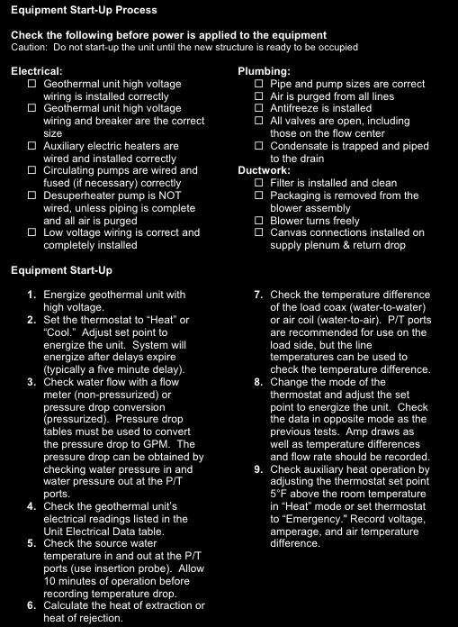
50 START UP PROCEDURE 50


51 EQUIPMENT START- UP FORM XIII. REVISION TABLE 51
52 Date: By: Page: Description: GT 34 Changed flow from 9 to 30 GPM p/tom E GT Updated nomenclature p/ec N01 10 Nov 2014 GT Corrected 7,8 & 10 ton AHRI data points 04 Aug 2014 GT 35 Added water connection fitting size table 29 July 2014 GT Updated single phase and added 3 phase wiring diagrams 28 July 2014 GT Changed CFM p/ecn N01 52

53 Greenville, IL & Mitchell, SD 20D150-01NN 2012 Enertech Global, LLC. All Rights Reserved 15708G 53
Installation & Operation Manual Hydronic
 Installation & Operation Manual Hydronic Installation & Operation Manual Engineering Specifications GeoSource Hydronic Models RGS-W036 RGS-W120 This Page Intentionally Left Blank Table of Contents I. Key
Installation & Operation Manual Forced Air
 Installation & Operation Manual Forced Air Installation & Operation Manual Engineering Specifications ECONAR ColdClimate Series Forced Air Models REC-V036 REC-V060 Table of Contents I. Key & Legend...
Installation and Operating Instructions. GeoSource DualTEK. Vertical and Horizontal Forced Air/Hydronic GV/GH 36 Thru 67 Series
 1 Installation and Operating Instructions GeoSource DualTEK Vertical and Horizontal Forced Air/Hydronic GV/GH 36 Thru 67 Series GeoSource DualTEK Vertical Unit Air Filter Blower Air Coil Contactor Transformer
GTIP60 ISO GT Series, Inch Pounds - 60 Hz GT (iso) Spec Guide Drawings Spec Sheets Low Temp Heating P/T Charts
 Spec Guide Drawings Spec Sheets Low Temp Heating P/T Charts") GTIP60 ISO GT Series, Inch Pounds 60 Hz GT010070 (iso) Spec Guide Drawings Spec Sheets Low Temp Heating P/T Charts Rev: 903 Rev 1 Revisions: 31103 Changed HZ dwg to field convertible 5902 changed Unit
GTIP60 ISO GT Series, Inch Pounds 60 Hz GT010070 (iso) Spec Guide Drawings Spec Sheets Low Temp Heating P/T Charts Rev: 903 Rev 1 Revisions: 31103 Changed HZ dwg to field convertible 5902 changed Unit
*20D082-05NN* 20D082-05NN
 2506 South Elm Street Greenville, IL 62246 www.enertechgeo.com info@enertechmfg.com HT Models Packaged Water-to-Air Horizontal Heat Pumps Engineering Data and Installation Manual Rev.: 25 May 2012D P/N:
MAC-120HE-03 Air-Cooled Chiller
 MAC-120HE-03 Air-Cooled Chiller 10 Ton / 120,000 BTUH Air-Cooled Chiller 380/415/460-3-50/60 1 HVAC Guide Specifications Air-Cooled Liquid Chiller Nominal Size: 10 Tons Multiaqua Model Number: MAC-120HE-03
TECHNICAL GUIDE DESCRIPTION SPLIT-SYSTEM AIR-COOLED CONDENSING UNITS MODELS: HF-07 FEATURES B-0703
 TECHNICAL GUIDE SPLIT-SYSTEM AIR-COOLED CONDENSING UNITS MODELS: HF-07 DESCRIPTION These Sunline 2000 units are completely assembled, piped and wired at the factory to provide one-piece shipment and rigging.
CHILLER. Operator s & Installation Manual
 CHILLER MODELS: CH1001-A Operator s & Installation Manual Release Date: August 9, 2002 Publication Number: 620914301 Revision Date: May 6, 2010 Revision: E Visit the IMI Cornelius web site at www.cornelius.com
GUIDE SPECIFICATIONS AQUARIUS ii
 Catalog (AP Technical Data Sheet) GUIDE SPECIFICATIONS AQUARIUS ii AP Series Two Stage R-410A GENERAL Units shall be performance certified to ISO standard 13256-1 for Water Loop Heat Pump, Ground Water
Rev B, 9/2/2009. Kodiak Chiller Overview
 930-0001 Rev B, 9/2/2009 Kodiak Chiller Overview Presentation Outline Phone: 781-933-7300 Lytron Technical Support Contact Information 3 Introduction 4 Part I: Unpacking 5 Part II: Installation 7 Part
MAC-036HE-02-L High Efficiency Air-Cooled Chiller Air-Cooled Chillers for Global Residential and Light Commercial Micro Climates Rev 1.
 MAC-036HE-02-L High Efficiency Air-Cooled Chiller Air-Cooled Chillers for Global Residential and Light Commercial Micro Climates Rev 1.1 HVAC Guide Specifications Air-Cooled Liquid Chiller with Low Ambient
MAC-048HE-01-L High Efficiency Air-Cooled Chiller Air-Cooled Chillers for Global Residential and Light Commercial Micro Climates Rev 1.
 MAC-048HE-01-L High Efficiency Air-Cooled Chiller Air-Cooled Chillers for Global Residential and Light Commercial Micro Climates Rev 1.1 HVAC Guide Specifications Air-Cooled Liquid Chiller with Low Ambient
MAC N-407 Air-Cooled Chiller
 MAC036-01-N-407 Air-Cooled Chiller Air-Cooled Chillers for Global Residential and Light Commercial MicroClimates MAC036 NOMENCLATURE BREAKDOWN MAC036-01 - N - 407 Refrigerant Type Air-Cooled Chiller 036=
INSTALLATION NORTHERN HEAT PUMP. XTERRA SERIES Horizontal and Vertical, Single and Dual Stage Geothermal Heat Pumps: FORCAIR AQUA2 SOURC3 TERRA SERIES
 NORTHERN HEAT PUMP TERRA SERIES ENERGY EXTRACTION SYSTEM INSTALLATION And Maintenance Manual XTERRA SERIES Horizontal and Vertical, Single and Dual Stage Geothermal Heat Pumps: FORCAIR AQUA2 SOURC3 TABLE
MAC-060HE-01-L High Efficiency Air-Cooled Chiller Air-Cooled Chillers for Global Residential and Light Commercial Micro Climates Rev 1.
 MAC-060HE-01-L High Efficiency Air-Cooled Chiller Air-Cooled Chillers for Global Residential and Light Commercial Micro Climates Rev 1.2 HVAC Guide Specifications Air-Cooled Liquid Chiller with Low Ambient
MACH N-407 Heat Pump Air-Cooled Chiller
 MACH060-01-N-407 Heat Pump Air-Cooled Chiller Heat Pump Air-Cooled Chillers for Global Residential and Light Commercial Microclimates MACH NOMENCLATURE BREAKDOWN MACH-060-01 - N - 407 Refrigerant Type
GUIDE SPECIFICATIONS. WW Series Water-to-Water Reverse Cycle Chillers & Low Temp Boilers. WW Reverse Cycle Chillers / Low Temperature Boilers
 GUIDE SPECIFICATIONS WW Series Water-to-Water Reverse Cycle Chillers & Low Temp Boilers WW024-072 Reverse Cycle Chillers / Low Temperature Boilers GENERAL Units shall be Underwriter Laboratories (UL) listed
Condensing Unit Installation and Operating Instructions
 Bulletin WCU_O&I 01 June 2003 Condensing Unit Installation and Operating Instructions WCU Air Cooled Condensing Unit Table of Contents Section 1. Section 2. Section 3. Section 4. Section 5. Section 6.
DLCLRA. INSTALLATION INSTRUCTIONS Outdoor Unit Single Zone Ductless System Sizes 36 to 58 TABLE OF CONTENTS
 DLCLRA INSTALLATION INSTRUCTIONS Outdoor Unit Single Zone Ductless System Sizes 36 to 58 Fig. 1 - Size 36 TABLE OF CONTENTS PAGE SAFETY CONSIDERATIONS... 2 PARTS LIST... 3 SYSTEM REQUIREMENTS... 4 WIRING...
EarthLinked HC Series Compressor Unit R-410A Quik-Start Instructions
 EarthLinked HC Series Compressor Unit R-410A Quik-Start Instructions CONTENTS PAGE Pre-Installation 3 Placement & Mechanical Information 4 System Application Options 11 Antifreeze Protection 14 Electrical
EarthLinked SCW Series Compressor Unit R-410A Quik-Start Instructions
 EarthLinked SCW Series Compressor Unit R-410A Quik-Start Instructions CONTENTS PAGE Pre-Installation 3 Placement & Mechanical Information 6 System Application Options 12 Antifreeze Protection 13 Electrical
EarthLinked SW Series Compressor Unit R-410A Quik-Start Instructions
 EarthLinked SW Series Compressor Unit R-410A Quik-Start Instructions CONTENTS PAGE Pre-Installation 3 Placement & Mechanical Information 4 System Application Options 10 Antifreeze Protection 14 Electrical
PACKAGE AIR CONDITIONER
 PACKAGE AIR CONDITIONER FORM NO. ATZ-206 TZAA- HIGH EFFICIENCY SERIES NOMINAL SIZE 10 TON [35.2 kw] 10 TON MODEL [35.2 kw] This product is shipped with a nitrogen holding charge that must be vented prior
PACKAGED AIR COOLED Product Data Catalog
 PACKAGED AIR COOLED Product Data Catalog MODELS ASP-10A ASP-15A ASP-20A ASP-00P ASP-00F ASP-00G A MEMBER OF MARDUK HOLDING COMPANY, LLC The Leader in Modular Chillers ETL and CSA Approved CHILLER MODULES
CROWN. Boiler Co. Santa-Fe Series. Hydronic Air Handlers INSTALLATION, OPERATION & MAINTENANCE INSTRUCTIONS
 CROWN Boiler Co Santa-Fe Series Hydronic Air Handlers INSTALLATION, OPERATION & MAINTENANCE INSTRUCTIONS These instructions must be affixed on or adjacent to the air handler Models: SAC049A20 SAC059A25
CH250 AND CH251 CHILLERS
 CH250 AND CH251 CHILLERS Operator s & Installation Manual Release Date: April 19, 2004 Publication Number: 620914801 Revision Date: May 15, 2015 Revision: G Visit the Cornelius web site at www.cornelius.com
INSTALLATION, OPERATING & MAINTENANCE INSTRUCTIONS FOR 350 SERIES CIRCULATION HEATERS
 INDEECO Circulation Heaters are designed to provide years of trouble free operation if properly installed and maintained. Please read and follow these instructions for installing and maintaining the heater.
CAH SERIES INSTALLATION & MAINTENANCE MODELS CAH CAH
 CAH SERIES INSTALLATION & MAINTENANCE MODELS CAH 33-44-50 CAH 49-54-70 CAH VARIABLE SPEED AIR HANDLERS DIMENSIONS... 3 TECHNICAL SPECS... 4 INSTALLATION DON TS... 5 INSTALLATION DO S... 6 FREEZE STAT REQUIRED
INSTALLATION INSTRUCTIONS GEO PRIME TANK. (Patent Pending) GPC
 GPC") INSTALLATION INSTRUCTIONS GEO PRIME TANK (Patent Pending) GPC Table of Contents General Description 2 Installation 3 Flushing and Purging 5 Initial Start up 7 Adding or Checking Fluid 8 Replacing a Pump
INSTALLATION INSTRUCTIONS GEO PRIME TANK (Patent Pending) GPC Table of Contents General Description 2 Installation 3 Flushing and Purging 5 Initial Start up 7 Adding or Checking Fluid 8 Replacing a Pump
Standard and CELDEK Evaporative Cooler Modules Installation, Operation, and Maintenance Manual
 Standard and CELDEK Evaporative Cooler Modules Installation, Operation, and Maintenance Manual Standard Evaporative Cooler CELDEK Evaporative Cooler RECEIVING AND INSPECTION Upon receiving unit, check
EarthLinked CC Series Compressor Unit R-410A Quik-Start Instructions
 EarthLinked CC Series Compressor Unit R-410A Quik-Start Instructions CONTENTS PAGE Pre-Installation 3 Placement & Mechanical Information 4 System Application Options 11 Desuperheater Kit 15 Anti-Freeze
TABLE OF CONTENTS. NOTE: Read the entire instruction manual before starting the installation. TROUBLESHOOTING... 13
 R 410A Duct Free Split System Air Conditioner and Heat Pump Product Family: DFS4(A/H) System, DFC4(A/H)3 Outdoor, DFF4(A/H)H Indoor NOTE: Read the entire instruction manual before starting the installation.
WMHP Series R410a Heat Pump INSTALLATION INSTRUCTIONS
 WMHP Series R410a Heat Pump INSTALLATION INSTRUCTIONS **WARNING TO INSTALLER, SERVICE PERSONNEL AND OWNER** Altering the product or replacing parts with non authorized factory parts voids all warranty
Installation Instructions
 38MHR Outdoor Unit Single Zone Ductless System Sizes 09 to 24 Installation Instructions NOTE: Read the entire instruction manual before starting the installation. NOTE: Images are for illustration purposes
B. Unit construction shall comply with ASHRAE 15 Safety Code, NEC, and ASME applicable codes (U.S.A. codes).
.") Guide Specifications PART 1 GENERAL 1.01 SYSTEM DESCRIPTION Microprocessor controlled, air-cooled liquid chiller utilizing scroll compressors, low sound fans, hydronic pump system and optional fluid storage
Guide Specifications PART 1 GENERAL 1.01 SYSTEM DESCRIPTION Microprocessor controlled, air-cooled liquid chiller utilizing scroll compressors, low sound fans, hydronic pump system and optional fluid storage
EarthLinked SC Series Compressor Unit R-407C Quik-Start Instructions
 EarthLinked SC Series Compressor Unit R-407C Quik-Start Instructions CONTENTS PAGE Pre-Installation 3 Placement & Mechanical Information 4 System Application Options 11 Desuperheater Kit 15 Antifreeze
EC SERIES MODEL NOMENCLATURE
 EC SERIES Table of Contents Model Nomenclature...1 Introduction...2 Initial Inspection...2 General Description...2 Moving and Storage...2 Safety Considerations...2 Location...2 Installation...2 Condensate
PRE-ASSEMBLED RADIANT CONTROL PANEL INSTALLATION MANUAL
 FloorHeat PRE-ASSEMBLED RADIANT CONTROL PANEL INSTALLATION MANUAL Thank you for purchasing this radiant control panel assembly. Following are some important notes that will make the installation successful.
water to water heat pumps
 AQUARIUS WW SERIES water to water heat pumps O ur Aquarius WW Series water-cooled modular reverse cycle chillers are designed to meet all your replacement or new construction chiller requirements. Specifically
CHILLER. Model CH3000. Operator s & Installation Manual
 CHILLER Model CH3000 Operator s & Installation Manual Release Date: February 14, 2011 Publication Number: 620054173OPR Revision Date: May 08, 2014 Revision: B Visit the Cornelius web site at www.cornelius.com
Water to Water Geothermal Heat Pump
 Water to Water Geothermal Heat Pump Installation & Operating Instructions Model: THA/THT-*** Application Geo source closed loop or ground water Hydronic water heat/cool output Air handler, water coil,
This manual should be maintained in legible condition and kept adjacent to the heat pump or in a safe place for future use.
 Perfectemp Swimming Pool Heat Pump CE OWNER S MANUAL Models PT4, PT6, and PT8 R C LISTE D 9900276 US This manual should be maintained in legible condition and kept adjacent to the heat pump or in a safe
T-Series Air Conditioner T15 Model
 INSTRUCTION MANUAL T-Series Air Conditioner T15 Model Protecting Electronics. Exceeding Expectations. McLean Cooling Technology 11611 Business Park Blvd N Champlin, MN 55316 USA Tel 763-323-8200 Fax 763-576-3200
Surna 25-Ton Chiller Operating & Maintenance Manual
 www.surna.com 303.993.5271 Surna 25-Ton Chiller Operating & Maintenance Manual Models: 300F3-3. 300F4-3, 300FW-3 Revised: July 2015 Table of Contents Warranty Information 4 Limited Warranty 4 Limitation
ENGINEERING SPECIFICATIONS
 ENGINEERING SPECIFICATIONS RH-24-HAC-P-1L-C-SDE*F Horizontal Single Stage R410a Model Size 24 Reversing (Heating AND Cooling) 208/230-1-60VAC Liquid to Air Geothermal Heat Pumps Maritime Geothermal Ltd.
Installation and Maintenance Manual TA Series
 Installation and Maintenance Manual TA Series Copyright 2012 Bosch, Inc All rights reserved Table of Contents TA Series 3 Table of Contents Model Nomenclature...3 Initial Inspection...4 General Description...4
T-Series Air Conditioner T20 Model
 INSTRUCTION MANUAL T-Series Air Conditioner T20 Model Protecting Electronics. Exceeding Expectations. McLean Cooling Technology 11611 Business Park Blvd N Champlin, MN 55316 USA Tel 763-323-8200 Fax 763-576-3200
Owner s Manual Therma-Stor II Heat Recovery System
 PO Box 8680 Madison, WI 53708 TS-138C Revised 8/08 Owner s Manual Therma-Stor II Heat Recovery System Installation, Operation & Service Instructions Read and Save These Instructions Table Of Contents 1.
ENGINEERING SPECIFICATIONS
 ENGINEERING SPECIFICATIONS RH-12-HAC-P-1L-C-SDE*F Horizontal Single Stage R410a Model Size 12 Reversing (Heating AND Cooling) 208/230-1-60VAC Liquid to Air Geothermal Heat Pumps Maritime Geothermal Ltd.
Commercial High-Efficiency Condensing Units
 FORM NO. A22-194 REV. 2 Supersedes Form No. A22-194 Rev. 1 Commercial High-Efficiency Condensing Units RAWL High Efficiency 6.5 & 7.5 TON MODEL [22.86 & 26.38 kw] TABLE OF CONTENTS Model Number Designation...2
DOUBLE O-RING GEO-PRIME TANK Non-Pressurized Flow Center System INSTALLATION INSTRUCTIONS. Model: DORGPT-1 NOTE:
 INSTALLATION INSTRUCTIONS DOUBLE O-RING GEO-PRIME TANK Non-Pressurized Flow Center System Model: DORGPT-1 NOTE: This guide provides the installer with instructions specific to the Bard Double O-Ring Geo-Prime
TECHNICAL GUIDE. Description SPLIT-SYSTEM AIR-COOLED CONDENSING UNITS YD360, 480 & THRU 50 NOMINAL TONS YTG-B-0811
 Description These units are completely assembled, piped and wired at the factory to provide one-piece shipment and rigging. Each unit is pressurized with a holding charge of Refrigerant R-410A for storage
Combo Geothermal Heat Pump
 Combo Geothermal Heat Pump Installation & Operating Instructions Model: RU-VE* Application Geo source, loop or ground water fluid Forced air vertical cabinet output Standard left ducting return, easily
Standard and CELDEK Evaporative Cooler Modules Installation, Operation, and Maintenance Manual
 Standard and CELDEK Evaporative Cooler Modules Installation, Operation, and Maintenance Manual Standard Evaporative Cooler CELDEK Evaporative Cooler RECEIVING AND INSPECTION Upon receiving unit, check
Daikin Water Cooling, Heating, and High Capacity Booster Coils
 Installation and Maintenance Manual IM 900 Daikin Water Cooling, Heating, and High Capacity Booster Coils Group: Applied Air Part Number: IM 900 Date: February 2008 Types HI-F5, E-F5 2008 Daikin International
CELDEK Evaporative Cooler Module Installation, Operation, and Maintenance Manual. CELDEK Evaporative Cooler
 CELDEK Evaporative Cooler Module Installation, Operation, and Maintenance Manual CELDEK Evaporative Cooler RECEIVING AND INSPECTION Upon receiving unit, check for any interior and exterior damage, and
Installation and Service Manual
 Installation and Service Manual W-Series Liquid to Water Geothermal Heat Pump Two-Stage R410a Model Sizes 25-80 Maritime Geothermal Ltd. P.O. Box 2555 Petitcodiac, NB E4Z 6H4 (506) 756-8135 Email: info@nordicghp.com
Installation, Operating, and Maintenance Manual
 www.geo-flo.com Engineered Solutions Making Geothermal Easier Installation, Operating, and Maintenance Manual Part # 3619 Rev. 27APR2017 Geo-Booster Geo-Flo Products Corporation 905 Williams Park Drive
AHWG Remote Mount Hot Water Generator Module for TTP Series Outdoor Split Unit
 A Remote Mount Hot Water Generator Module for TTP Series Outdoor Split Unit Installation, Operation & Maintenance Instructions 97B0080N01 B Table of Contents Model Nomenclature Example 3 Description and
Operation Manual SCT14B and SCT18B. Inspection. 3 General Description. 3 General Requirements. 3 Standard Features.
 Spot Cooling Systems, Inc. 120 Century Drive Suite 00 Carrollton, TX 7006 00-6-776 Operation Manual SCT1B and SCT1B Warning! Improper installation, adjustment, alteration, service, or maintenance can cause
AP SERIES VOLTAGE DESIGNATION: 1-208/1/60 & 230/1/60 CABINET CONFIGURATION: VT - VERTICAL HZ - HORIZONTAL CF - COUNTERFLOW
 Table of Contents Model Nomenclature...1 Initial Inspection...2 General Description...2 Moving and Storage...2 Safety Considerations...2 Location...2 Installation...2 Condensate Drain...3 Duct System...3
GOLD Plus 30/40/60/80
 PLUS Line Indirect-Fired Water Heaters Series 3 Manual Installation Startup Maintenance Parts PLUS 100/110/119 GOLD Plus 30/40/60/80 Plus 40/60/80 This manual must only be used by a qualified heating installer/service
4201 Lien Rd Madison, WI Owner s Manual Therma-Stor III Heat Recovery System. Installation, Operation & Service Instructions
 4201 Lien Rd Madison, WI 53704 TS-140F Revised 09-10 Owner s Manual Therma-Stor III Heat Recovery System Installation, Operation & Service Instructions Read and Save These Instructions Table Of Contents
INSTALLATION INSTRUCTIONS WARRANTY
 QT FLOW CENTER INSTALLATION INSTRUCTIONS Fig. 1. Low Head Pump Center Flow Chart Fig. 2. High Head Pump Center Flow Chart NOTE: Read the entire instruction manual before starting the installation. WARRANTY
INSTALLATION INSTRUCTIONS and OPERATING MANUAL. *Aquastat is a registered trademark of Honeywell International, Inc.
 MODEL 3200-Plus Temp Limit / LWCO Control with Thermal Targeting for Water Boilers 120 VAC Input / 24 VAC Burner Circuit PATENT. 8,931,708; 8,844,834; 7,891,572; others pending INSTALLATION INSTRUCTIONS
AE R1 October to 5 Ton ZPS*K6 Copeland Scroll Two-Stage Compressors
 October 2017 1.5 to 5 Ton ZPS*K6 Copeland Scroll Two-Stage Compressors Safety Safety Instructions... 2 Safety Icon Explanation... 2 Instructions Pertaining to Risk of Electrical Shock, Fire, or Injury
R.A.S.E.R.S System. Installation Guide
 R.A.S.E.R.S System Installation Guide Contents R.A.S.E.R.S System components... 1 Required components for heating, cooling, and hot water...1 Provided...1 Not provided...2 Optional components...3 R.A.S.E.R.S
Heat Transfer Products, Inc. 120 Braley Road East Freetown, MA The first totally integrated multiple boiler management control.
 Heat Transfer Products, Inc. 120 Braley Road East Freetown, MA 02717 The first totally integrated multiple boiler management control. USING THIS MANUAL USING THIS MANUAL A. INSTALLATION SEQUENCE Follow
Condensing Unit Installation and Operating Instructions
 Bulletin ACU_O&I 02 August 2016 Condensing Unit Installation and Operating Instructions ACU Air Cooled Condensers Table of Contents Section 1. General Information... 2 Section 2. Refrigeration Piping...
INSTALLATION MB SERIES MANUAL TABLE OF CONTENTS MB SERIES ( INSTALLATION ) UNIT DESCRIPTION. FHP MB series are available in two models: VH CABINET:
 UNIT DESCRIPTION. FHP MB series are available in two models: VH CABINET:") MB SERIES ( INSTALLATION ) INSTALLATION MANUAL MB SERIES TABLE OF CONTENTS Unit Description...1 Installation...2 General...2 Safety Considerations...2 Moving and Storage...3 Location...3 Acoustical Considerations...3
MB SERIES ( INSTALLATION ) INSTALLATION MANUAL MB SERIES TABLE OF CONTENTS Unit Description...1 Installation...2 General...2 Safety Considerations...2 Moving and Storage...3 Location...3 Acoustical Considerations...3
SERVICE MANUAL. Bradford White ElectriFLEX HD (Heavy Duty) Commercial Electric Water Heater CEHD SERIES Immersion Thermostat Models
 Commercial Electric Water Heater CEHD SERIES Immersion Thermostat Models") Bradford White ElectriFLEX HD (Heavy Duty) Commercial Electric Water Heater CEHD SERIES Immersion Thermostat Models SERVICE MANUAL Troubleshooting Guide and Instructions for Service (To be performed ONLY
Bradford White ElectriFLEX HD (Heavy Duty) Commercial Electric Water Heater CEHD SERIES Immersion Thermostat Models SERVICE MANUAL Troubleshooting Guide and Instructions for Service (To be performed ONLY
INSTALLATION INSTRUCTIONS
 INSTALLATION INSTRUCTIONS T CLASS TSA Series 6 to 20 Ton AIR CONDITIONERS 6 20 TONS 506147 01 06/11 Supersedes 3/11 Litho U.S.A. RETAIN THESE INSTRUCTIONS FOR FUTURE REFERENCE IMPORTANT The Clean Air Act
PROAIR Air Conditioner. CR29 Model INSTRUCTION MANUAL nvent Rev. I P/N
 PROAIR Air Conditioner CR29 Model INSTRUCTION MANUAL Rev. I P/N 89104461 TABLE OF CONTENTS Warranty and Return Policy...2 RECEIVING THE AIR CONDITIONER...3 HANDLING AND TESTING THE AIR CONDITIONER...3
T-SERIES Air Conditioner. T43 Model INSTRUCTION MANUAL nvent Rev. I P/N
 T-SERIES Air Conditioner T43 Model INSTRUCTION MANUAL Rev. I P/N 10-1008-145 TABLE OF CONTENTS Warranty and Return Policy...2 IMPORTANT NOTICE...2 RECEIVING THE AIR CONDITIONER...3 HANDLING AND TESTING
AHWG Remote Mount Hot Water Generator Module
 A Remote Mount Hot Water Generator Module For GT-PE (50YPS) Series Outdoor Split Unit Installation, Operation & Maintenance Instructions 97B0080N02 B Model Nomenclature Example 3 Description and Installation
INSTALLATION INSTRUCTIONS
 INSTALLATION INSTRUCTIONS T CLASS TPA Series HEAT PUMPS 7.5 TO 10 TONS 506148 01 12/08 Litho U.S.A. RETAIN THESE INSTRUCTIONS FOR FUTURE REFERENCE IMPORTANT The Clean Air Act of 1990 bans the intentional
ES Series. Installation and Maintenance Manual
 ES Series Installation and Maintenance Manual 8733922027 (2014/01) Table of Contents Model Nomenclature...1 Initial Inspection...2 General Description...2 Moving and Storage...2 Safety Considerations...2
ENGINEERING SPECIFICATIONS
 ENGINEERING SPECIFICATIONS W-150-H-P-*D-PP Vertical Dual Refrigeration Circuit Scroll Compressors R410a Refrigerant Nominal Size 12 Ton Non-Reversing (Heating OR Cooling) Commercial Hydronic Geothermal
AMERICAN EQUIPMENT SYSTEMS A Division Of Trevor-Martin Corporation th Terrace North Clearwater, Florida 33762
 AMERICAN EQUIPMENT SYSTEMS A Division Of Trevor-Martin Corporation 4151 112 th Terrace North Clearwater, Florida 33762 COMMERCIAL REFRIGERANT DESUPERHEATER WASTE HEAT RECOVERY INSTALLATION/OPERATION/MAINTENANCE
GS SERIES. Table of Contents CABINET CONFIGURATION: VT - VERTICAL HZ - HORIZONTAL CF - COUNTERFLOW
 Table of Contents Model Nomenclature...1 Initial Inspection...2 General Description...2 Moving and Storage...2 Safety Considerations...2 Location...2 Installation...2 Condensate Drain...3 Duct System...3
Installation & Operations Manual
 Installation & Operations Manual WS/WD MODELS WATER-TO-WATER HEAT PUMPS & HYDRONIC AIR HANDLERS Revision D 20D817-01NN 20D817-01NN Table of Contents Section 1: Model Nomenclature and AHRI Performance Data
RV Products Division INSTALLATION INSTRUCTIONS FOR SERIES PACKAGE AIR CONDITIONER
 RV Products Division INSTALLATION INSTRUCTIONS FOR 46413 SERIES PACKAGE AIR CONDITIONER 1. WARNINGS IMPORTANT NOTICE These instructions are for the use of qualified individuals specially trained and experienced
Reinventing Energy Efficiency
 Commercial WATER2AIR EC LARGE SERIES Reinventing Energy Efficiency www.fhp-mfg.com Environmental stewardship is a core philosophy for FHP Manufacturing from design to production to the reduction in our
WineZone Ceiling Mount Ductless Split 15
 WineZone Ceiling Mount Ductless Split 15 Requires an HVAC technician to install and charge with R-22 refrigerant. Easy to install. Unit plugs into wall outlet. Industrial grade unit for longer life. Indoor
Commercial High-Efficiency Condensing Units
 FORM NO. A22-193 REV. 3 Supersedes Form No. A22-193 Rev. 2 Commercial High-Efficiency Condensing Units 15 & 20 TON MODEL [52.8 & 70.3 kw] 10 & 12.5 TON MODEL [35.2 & 44.0 kw] 10 THROUGH 20 NOMINAL TON
Installation, Operating, and Maintenance Manual
 www.geo-flo.com Engineered Solutions Making Geothermal Easier Installation, Operating, and Maintenance Manual To/From Ground Loop To/From Heat Pump Part # 3761 Rev. 03OCT2016 NP and NP Plus Non-Pressurized
INSTALLATION, OPERATING & MAINTENANCE INSTRUCTIONS FOR 870 SERIES INDUSTRIAL CONTROL PANELS
 INSTALLATION, OPERATING & MAINTENANCE INSTRUCTIONS FOR 870 SERIES INDUSTRIAL CONTROL PANELS GENERAL INDEECO Industrial Control Panels are designed to provide years of trouble free operation if properly
Nominal Capacity 024 = 7 kw (2 tons) 036 = 10.5 kw (3 tons) 048 = 14 kw (4 tons) 060 = 17.5 kw (5 tons)
 036 = 10.5 kw (3 tons) 048 = 14 kw (4 tons) 060 = 17.5 kw (5 tons)") ENGINEERING DATA HEAT PUMP OUTDOOR UNITS HP40 50HZ Capacity 6.2 to 16.3 (21 200 to 55 500 Btuh) Heating Capacity 6.4 to 16.1 (21 800 to 55 500 Btuh) Bulletin No. 490088 October 2004 Supersedes August 1999
ENGINEERING DATA HEAT PUMP OUTDOOR UNITS HP40 50HZ Capacity 6.2 to 16.3 (21 200 to 55 500 Btuh) Heating Capacity 6.4 to 16.1 (21 800 to 55 500 Btuh) Bulletin No. 490088 October 2004 Supersedes August 1999
PROAIR Air Conditioner. CR23 Model INSTRUCTION MANUAL nvent Rev. D P/N
 PROAIR Air Conditioner CR23 Model INSTRUCTION MANUAL Rev. D P/N 89112522 TABLE OF CONTENTS Warranty and Return Policy...2 RECEIVING THE AIR CONDITIONER...3 HANDLING AND TESTING THE AIR CONDITIONER...3
INSTALLATION INSTRUCTIONS
 INSTALLATION INSTRUCTIONS HB Series Geothermal Heat Pump Sizes 018, 024, 030, 036, 042, 048, 060 TE: Read the entire instruction manual before starting the installation. TABLE OF CONTENTS PAGE. SAFETY
UPM I. Unit Protection Module. Installation and Operation Manual (2015/06)
") UPM I Unit Protection Module Installation and Operation Manual 6 720 220 321(2015/06) 2 Key to Symbols Contents Key To Symbols...2 Warnings...2 Specifications... 3 Unit Protection Module (UPM)....3 Power
UPM I Unit Protection Module Installation and Operation Manual 6 720 220 321(2015/06) 2 Key to Symbols Contents Key To Symbols...2 Warnings...2 Specifications... 3 Unit Protection Module (UPM)....3 Power
Call us today! (800)
") 500 TON AIR-COOLED CHILLER PA-ACCTR-500 Call us today! (800)341-4297 The 500-Ton portable chiller package features a Trane RTAC chiller unit. Trane leads the industry in providing some of the most reliable,
500 TON AIR-COOLED CHILLER PA-ACCTR-500 Call us today! (800)341-4297 The 500-Ton portable chiller package features a Trane RTAC chiller unit. Trane leads the industry in providing some of the most reliable,
CFF-500 CHILLER. Operator s & Installation Manual. Release Date: November 3, 1996 Publication Number: Revision Date: March 25, 2014 Revision: F
 CFF-500 CHILLER Operator s & Installation Manual Release Date: November 3, 1996 Publication Number: 90667 Revision Date: March 25, 2014 Revision: F Visit the Cornelius web site at www.cornelius.com for
T-SERIES Air Conditioner. T29 Model INSTRUCTION MANUAL nvent Rev. I P/N
 T-SERIES Air Conditioner T29 Model INSTRUCTION MANUAL Rev. I P/N 89104464 TABLE OF CONTENTS Warranty and Return Policy...2 IMPORTANT NOTICE...2 RECEIVING THE AIR CONDITIONER...3 HANDLING AND TESTING THE
SKYPAK II, 3 Ton Series, gives you a
 SKYPAK II 3 ton Heating And Cooling self-contained Package SKYPAK II, 3 Ton Series, gives you a complete air-conditioning and heating system as an all in one package unit. Designed for convenient through-the-wall
CHILLER. Operator s & Installation Manual
 CHILLER MODEL: CFF-500 Operator s & Installation Manual Release Date: November 3, 1996 Publication Number: 90667 Revision Date: May 10, 2010 Revision: E Visit the IMI Cornelius web site at www.cornelius.com
Refrigeration/Troubleshooting Manual
 Refrigeration/Troubleshooting Manual P.O. Box 245 Syracuse, NY 13211 www.roth-america.com 888-266-7684 P/N: 2300100910 Table of Contents: Section 1: Geothermal Refrigeration Circuits Overview... 2 Water-to-Air
PROAIR Air Conditioner. CR43 Model INSTRUCTION MANUAL nvent Rev. H P/N
 PROAIR Air Conditioner CR43 Model INSTRUCTION MANUAL Rev. H P/N 10-1008-130 TABLE OF CONTENTS Warranty and Return Policy...2 RECEIVING THE AIR CONDITIONER...3 HANDLING AND TESTING THE AIR CONDITIONER...3
Call us today! (800)
") PA-ACCTR-200 Call us today! (800)341-4297 The 200-Ton portable chiller package features a Trane RTAC chiller unit. Trane leads the industry in providing some of the most reliable, efficient and quiet chiller
PA-ACCTR-200 Call us today! (800)341-4297 The 200-Ton portable chiller package features a Trane RTAC chiller unit. Trane leads the industry in providing some of the most reliable, efficient and quiet chiller
PARALLEL RACK SYSTEM INSTALLATION & OPERATIONS MANUAL With Master Rack Compressor Sequencer
 PARALLEL RACK SYSTEM INSTALLATION & OPERATIONS MANUAL With Master Rack Compressor Sequencer 5/16 Rev. A 57-02509 2 Contents INTRODUCTION... 4 WARNING LABELS AND SAFETY INSTRUCTIONS... 5 PS SERIES PARALLEL