Operation Manual. Model 600BB. Moisture Sensor Kit for Large Square Balers For New Holland BigBaler and Case IH LB BB-OPR 5/14
|
|
|
- Kathryn Goodwin
- 5 years ago
- Views:
Transcription

1 Operation Manual Model 600BB Moisture Sensor Kit for Large Square Balers For New Holland BigBaler and Case IH LB BB-OPR 5/14
2 (intentionally blank) 2
3 Harvest Tec Model 600BB Operation Table of Contents Page Introduction 4 System Requirements 4 Safety Safety Decals 5 5 Connecting Power and Communications Harness 6 Communicating through the ISOBUS Monitor 7-15 Operation of the ISOBUS Monitor 16 Description of Screens and Menus of the Harvest Tec Monitor 16 Operating Instructions 17 Automatic Mode 17 Description of Additional Screens and Menus Diagnostics 18 Setup Mode 19 Job Records 20 Setting Up Bale Parameters for Initial Use 21 Baling Rate Setup 21 Operating Instructions for Additional Screens Diagnostics 22 Job Records Baler Harness/Wiring Diagram with Baler Interface Pin Outs for Harnesses and Wiring Diagram Maintenance 28 Diagnostics 28 Dielectric Grease Connections 28 Battery Connections 28 Winter Storage Common Questions Troubleshooting 29 Parts Breakdown Controls and Harnesses-Dual Channel Processor (DCP) 30 Star Wheel Moisture Sensor and Baler Rate Sensors 31 Optional Touch Screen Display (TSD) 31 Warranty Statement 3
4 Introduction Thank you for purchasing a 600BB Moisture Sensor Kit. The 600BB Moisture Sensor Kit is designed to work with the baler s ISOBUS and display on the New Holland Intelliview 3 or Intelliview 4, Case IH Pro 300 or Pro 700. The 600BB Moisture Sensor offers these advantages: 1. Operation coordinated with baler operation 2. Less cab clutter providing better visibility 3. Ease of use with all information on one screen 4. Records kept together 5. The system is ready for future updates This manual will take you through the steps of installing the moisture sensor. Please read this manual carefully to learn how to install the equipment correctly. Failure to do this can result in personal injury or equipment malfunction. If you are unsure about installing the system after consulting this manual, contact your local authorized dealership for additional assistance or look for the contact information on the back cover of this manual. If you are in need of parts for the system please view the Parts Breakdowns toward the back of this manual and contact your local authorized dealer to order the parts. For instructions on the operation of the 600BB Moisture Sensor Kit please refer to the Balers Operations Manual. Right and Left sides are determined by facing in the direction of forward travel. System Requirements The Baler Control Module (BCM) must have Version or higher. For the CNH Baler to receive the ThirtyPlus or CropSaver System messages regarding Status, Moisture and preservative, and display this information on the Baler Work Screen, the software in the Baler Control Module (BCM) needs to be updated to version or higher. This software will be available in EST patch 4 (May at dealerships) and EST (June at dealerships). Dealers can log an ASIST incident and request the BCM software from CNH Technical Support Services if they need the software prior to those release dates. 4


5 Safety Carefully read all the safety signs in this manual and on the applicator before use. Keep signs clean and in good working order. Replace missing or damaged safety signs. Replacement signs are available from your local authorized dealer. See your installation manual for under the replacement parts section for the correct part numbers. Keep your applicator in proper working condition. Unauthorized modifications to the applicator may impair the function and/or safety of the machine. Carefully read and understand all of the baler safety signs before installing or servicing the baler. Always use the supplied safety equipment on the baler to service the applicator. Safety Decals Number 1 Disconnect power before servicing. Part no. DCL-8003 Number 4 Read and understand the operator s manual before using or working around the equipment. Part no. DCL

6 Connecting Power and Communication Harnesses The harnesses ( TM & LS) are located at the front of the baler near the hitch and at the back of the tractor near the drawbar. See arrow below. Make sure all connection wires are free between the hitch of the baler and the back of the tractor, especially when tractor is turning away. WARNING and Safety Precaution: Stop tractor engine and shift to park, set brakes and remove key before leaving the tractor. 6
7 Communicating through the ISOBUS Monitor to Utilize the Moisture Sensor Kit When the 600 Series processor is connected to the baler and powered on the first time it is necessary to load the object pools to the Virtual Terminal (VT). Icon (1) indicates that the object pools are in the process of loading and saving to the VT. Note that if the language selection of the VT is changed, the corresponding object pool must be reloaded to the VT. The object pool loading process takes approximately two minutes to complete. 1 2 Once the object pools have been loaded and Icon (1) disappears from the upper left corner of the display, press the NEXT IMPLEMENT button (2) and verify that the 600 Series object pools appear on the Virtual Terminal. 7
 to return to")
 on the side of")
8 3 After verifying that the 600 Series object pool is loaded and the 600 Series System operating screens are displayed on the VT, press the NEXT IMPLEMENT button (3) to return to the baler work screen page. 4 Press the bottom button of the Menu Bar with the down arrow in corner (4) on the side of the screen to continue down the Menu Bar below the USER SETTING icon. 8
.")

9 Scroll through the Menu bar until the INFORMATION icon (5) is visible. Press the INFORMATION button so the Information page appears. Verify that the controller software loaded to the baler is version or higher. If not, contact the dealer to update firmware in Baler Control Module (BCM). If the controller software displays version or higher proceed, to configuring the baler for the 600 Series System by pressing the MACHINE SETUP button (6). 7 Once the MACHINE SETUP icon has been selected, the Machine Setup page will appear, and the icon will be backlit in orange. Press the MACHINE SETUP icon (7) again to go to the second page of the Machine Setup. 9
10 8 The second page of the Machine setup screens is identified by the three light gray buttons in the Menu Bar. Press and hold the second light gray button (8) for 10 seconds or until the display switches to displaying Dealer Mode. 9 Once Dealer Mode has been entered, select the down arrow in the Menu Bar (9) to scroll to the second Dealer Mode Screen where Moisture is a selection. 10
, based on the configuration of your 600 Series system.")
11 10 Once you have reached the second Dealer Mode screen, select the area under Moisture (10). Note that the box below Moisture will likely be the default NOT INSTALLED. 11 Select the proper configuration setting from the pop up menu (11), based on the configuration of your 600 Series system. This configuration setting allows the baler to properly display the information it is receiving from the 600 Series system on the baler working screen. Select DCP. Note that HT500C2 moisture only is not ISOBUS compatible and is not an option in North America. 11
12 12 Once the configuration has been set press the MACHINE SETUP icon (12) to return to the Machine Setup Screen and the Menu Bar. 13 Press the arrow down button at the bottom of the Menu Bar (13) to scroll down thru the Menu Bar until you reach the SCREEN SETUP pages

13 14 Select the icon for SCREEN SETUP 1 (14) so the Screen Setup 1 screen appears. Select how you would like to have the screen configured to show a combination of baler and 600 Series system information by selecting the boxes. When you select one of the boxes, a popup screen will appear that shows the selections available. Selections related to the 600 Series system include Moisture and Moisture Bale. These are noted by arrows in the image above and in the next image. Scroll to additional options in the popup window by pressing the down arrow on the side of the popup window (15)
 and adjust the Moisture Alarm Settings in the Field Setting Screen. Note that the low moisture alarm must be set lower than the high moisture alarm.")
14 16 Once the Screen Setup pages have been configured, scroll back up to the top of the Menu Bar by pressing the top button in the Menu Bar with the up arrow (16) Select the FIELD SETTING icon (17) and adjust the Moisture Alarm Settings in the Field Setting Screen. Note that the low moisture alarm must be set lower than the high moisture alarm. The moisture alarms can be turned off by setting the low setting <9% and the high setting >70%. When the alarms are turned off, they will say OFF next to the values. Select the MAIN SCREEN 1 icon (18) from the Menu Bar. 14

15 Verify that your MAIN SCREEN 1 and MAIN SCREEN 2 are configured as you would like them displaying the information you would like visible during operation. During operation, information for the 600 Series System that you have chosen to display will be displayed on the Baler Work Screen. You can cycle back and forth between the Baler Work Screen and the 600 Series System Work Screen by pressing the NEXT IMPLEMENT button (19) during operation. Harvest Tec Icons signified by arrows are listed below. 19, 20, 21, and 24 are visible with the Moisture Only 600BB System. All would be visible with a complete applicator system. (19) Next Implement Button (20) Moisture Content % (21) Last Bale Average Moisture Content % (22) Actual Application Rate of Preservative (23) Target Application Rate of Preservative (24) DCP Status Icon (25) Tagger Status Icon The DCP Status Icon (24) indicates the DCP is connected to the baler. An X over the DCP Status Icon indicates the DCP System is: A) Not in an application mode B) Paused through a. Manual Pause b. Hay Indicator Pause c. Baler End Of Row (EOR) Pause (PTO speed < 600 rpm) When the Tagger Status Icon (25) is visible the DCP System is indicating the Tagger is activated. When the DCP System is not in Application Mode or has been paused there will be an X over the Tagger Status Icon. 15
16 Operation of the ISOBUS Monitor Description of Screens and Menus of the ISOBUS Monitor All Buttons are color coded and labeled. Selections can be made by touching the actual screen choice or by touching the numbers down the right side menu which are color and numerically coded to correlate with the same selection. Listed below are the Main Menu Options. Main Menu of the Preservative Applicator Screen Automatic Mode ( 1 ) This operating mode allows the operator to watch the moisture content of crop and keep individual bale records. The following items are displayed in the mode while baling: Moisture, Baling Rate, Last Bale Average Moisture, and Tons Baled. Manual Mode ( 2 ) This operating mode allows the operator to also watch the moisture content of the crop and keep individual records. The following items are displayed in the mode while baling: Moisture, Baling Rate, Last Bale Average Moisture, and Tons Baled. Diagnostics ( 3 ) Allows operator to set the date and time. The installed software versions can also be viewed here. Setup Mode ( 4 ) This mode allows the operator to customize the applicators settings for their baler and baling needs. This mode allows changes to be made to the following areas: Application Rate, Baling Rate, Language, US or Metric units, and turn on/off the optional Hay Indicators. Job Records ( 5 ) Keeps track of up to 300 jobs with total product used, average moisture content, highest moisture content, tons baled, date of baling, and total number of bales made. Individual bales are also able to be viewed and the records can also be downloaded to a USB drive in this mode. 16
 After pushing the AUTOMATIC MODE key in the MAIN MENU screen, the following screen should appear: 3 1 2 4 5 6 1.")
17 Operating Instructions Automatic Mode will be used in the field to read both hay moisture content sensed by the star wheels and the operator s preset parameters to determine baling rate and tons per hour. Automatic Mode (or Manual Mode) After pushing the AUTOMATIC MODE key in the MAIN MENU screen, the following screen should appear: The moisture content is shown in the upper right hand corner (1) 2. Baling Rate and Application Rate (2) are shown in the middle. The application rate will always be zero. The target rate will show a number when the moisture of the hay exceeds the initial set point of 16%. The Baling Rate is calculated in the SETUP MODE. 3. The Graph (3) shows the moisture trend from the past 90 seconds in 3 second intervals. 4. The totals on the bottom of the screen show the total Tons Baled and # Used (4) (pounds of product used) for the current job. These numbers will reset to zero when a new Job Record is started. If operating with Bale Rate Sensors OFF total Tons Baled will be zero. 5. Last Bale (5) shows the average moisture content for the last bale. 6. Press the MAIN MENU (6) key to return to the opening screen. 17


18 The following pages provide additional screen functionality you may choose to use if you add preservative and or the tagging capabilities. Description of Additional Screens and Menus Use the below listed screen menus to navigate through all of the operation screens. Navigation through the screens is accomplished by using the touch screen and pressing the appropriate function. Diagnostics: 18


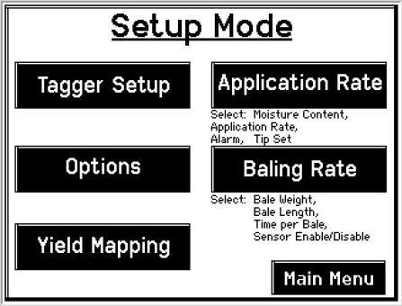
19 Setup Mode: 19


20 Job Records: 20
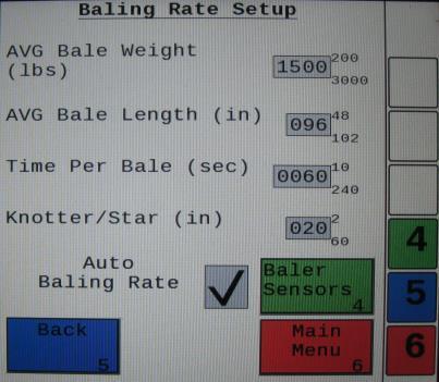
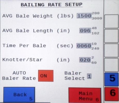
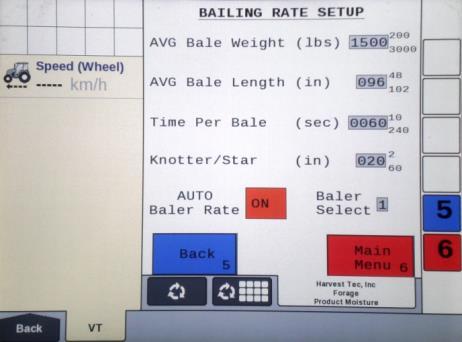
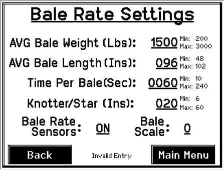
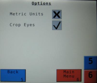
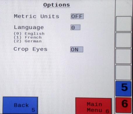
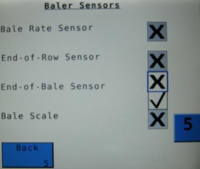
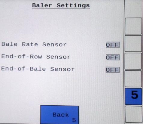
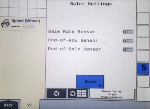
21 Setting Up Bale Parameters for Initial Use In the SETUP MODE you will set your initial baling rate. Baling Rate Setup After pushing the SETUP MODE key in the MAIN MENU screen, the top screen should appear: On this screen the operator will Select the BALING RATE SETUP (1) key. 2. Select the number to the right of AVG Bale Weight (Lbs) (2) : to adjust the weight of your bales. The key pad shown will display. Select any number combination in this screen within the min/max limits. The information will remain until it is changed again. 3. Select the number to the right of AVG Bale Length (In) (3): to adjust the length of your bales. Select any number combination in this screen within the min/max limits. The information will remain until it is changed again. 4. Select the number to the right of Time Per Bale (Sec) (4): to adjust the time it takes to make a bale. Select any number combination in this screen within the min/max limits. The information will remain until it is changed again. 5. Select the number to the right of Knotter/Star (5) to adjust the distance between the knotter and star wheel. To determine the distance, measure between the center of the starwheel and the center of the knotter. This is important so the job record correlates to the bale being made. 6. When the AUTO Bale Rate (6) sensors are ON the applicator will calculate your tons per hour automatically. When the AUTO Bale Rate (6) sensors are OFF a constant tons per hour (your inputed bale weight and time) will be used. Operating the unit with the AUTO Bale Rate sensors OFF will cause total tons per hour in Job Records to be left blank. Select the underlined word to toggle between ON or OFF. First Time and Annual Setup is checking with AUTO Bale Rate sensors OFF. 7. Selecting the Baler Select (7) will allow you to use the baler sensors if your baler is equiped with them from the factory. The baler sensors will come OFF as a default. If you choose to use the baler sensors be sure your baler is equipped with that option. For example, if you do not have an electronic bale length kit, turn the sensor to OFF. The baler End of Row sensors are triggered once the PTO speed goes below 600RPM. The End of Bale sensor is triggered by the tie cycle alarm. The Bale Scale sensor is for the baler equiped with a Chute Scale. Note: Baling on rough terrain or hills can cause the scale to give an inaccurate reading. Turn Bale Scale option OFF in the Bale Rate Screen and use AVG Bale Weight (2) reading as weight of bale. 8. Next select the Back (8) key found on the bottom left hand of the screen to return to the SETUP MODE screen, or select the MAIN MENU (9) key on the bottom right hand of the screen to return to the opening screen. 9. Select the OPTIONS (10) key to adjust the system between metric and standard units. The Crop Eyes can also be turned ON or OFF in the OPTIONS screen. Select the ON/OFF next to Crop Eyes to change this setting. Note: If you change languages youmay need to reset the system from the MAIN MENU screen

 followed by the time.")
 time. 2.")
22 Operating Instructions for Additional Screens Diagnostics After pressing the DIAGNOSTICS key in the MAIN MENU screen, the screen on the left should appear: To set date and time select the Set Date/Time (1) key. In the next screen enter the date (month, day, year format) followed by the time. When done select the OK (2) key. NOTE: The clock uses military (or 24 hour) time. 2. Select the Software Versions (3) key to check all software versions of modules attached to the Dual Channel Processor (DCP). 3. Press the MAIN MENU (4) key to return to the opening screen. 4
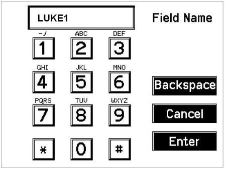
 will save all the previous bale records and open the Field Name (2) screen. 2. Use the key pad in the Field Name screen to enter up to an eight character field name.")
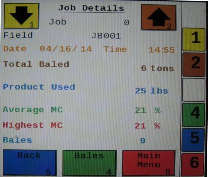
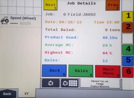
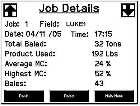
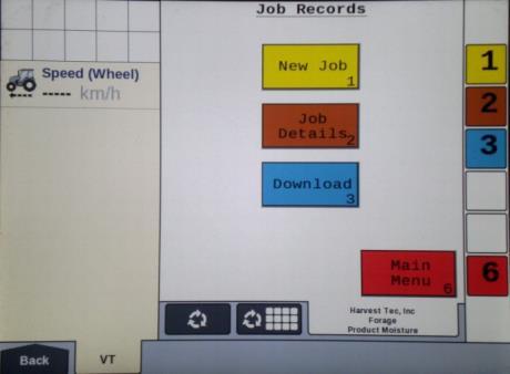
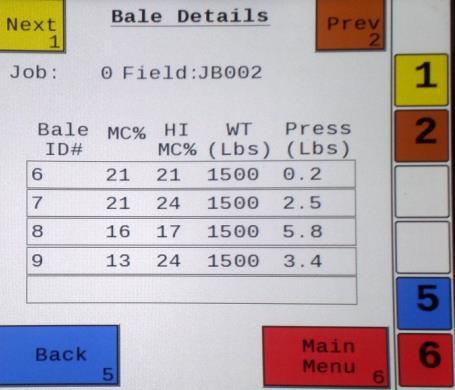
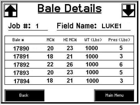
23 Job Records After pushing the JOB RECORDS key in the MAIN MENU screen, the upper left screen below should appear: Selecting New Job (1) will save all the previous bale records and open the Field Name (2) screen. 2. Use the key pad in the Field Name screen to enter up to an eight character field name. Use the asterisk key to move on to the next letter or number if they are identical. Use the pound sign (#) as a space between the characters. When you have completed the field name press enter. 3. Pressing Job Details (3) will open the Job Details screen. Use the Next and Prev (4) icons to view the different jobs. Job: 0 will always be your current and open job record. Press Back (5) to go to the Job Records screen or Main Menu (7) for the main screen. 4. Selecting Bales (6) at the center bottom of the screen will open a Bale Details (7) screen. This screen lets you look at the individual bale records for the first five bales made. Use the Next and Prev icons to scroll through five bales at a time. Select Back (5) to go to the Job Details screen or Main Menu (8) for the main screen. Continued on the next page 23
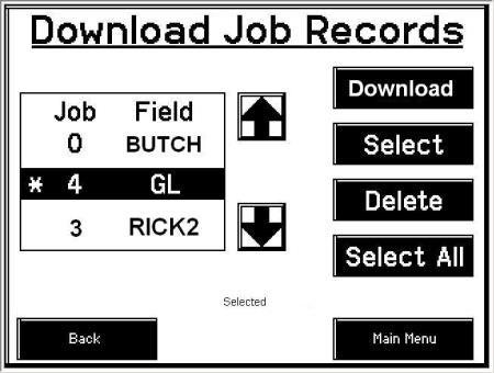
 you would like to download using the Next and Prev (10) icons to highlight the job(s).")
24 Continued Job Records Selecting the Download (9) key will open the Download Job Records screen. This screen lets you select jobs to download onto a USB drive. To download job records insert a USB drive into the port on the Dual Channel Processor. Select the job(s) you would like to download using the Next and Prev (10) icons to highlight the job(s). Once the desired jobs are selected press the Download (9) key. Press the Download key again to confirm. When the USB drive light goes off all the jobs selected will be saved. The jobs can then be opened on any computer with Excel or Notepad. To delete jobs highlight, select them and press Delete (11) followed by pressing Delete again for confirmation. Press Back to go to the Job Records screen or Main Menu for the main screen. 6. Pressing the Select (12) key will select or unselect the highlighted job. 7. Pressing the Select All (13) key will select all jobs, except for the current job (0). To unselect press the Back (14) key. 8. The job record in Excel will show as on the left above. The Bale ID column will need to be adjusted for proper viewing. 9. The job record in Notepad will show as on the right above. You will need to scroll right to see all the information. 24
25 Baler Harness/Wiring Diagram with Baler Interface A. The Baler Power/Communication Harness ( LS) will attach to the open port of the Tractor Harness ( TM) and run back to the Dual Channel Processor (DCP LS). Connect the large plug of the Baler Power/Communication Harness ( LS) to the bottom (shorter side) of the DCP. Attach the Baler Interface Harness ( VA) in between the short whip cable hardwired to the DCP and the main Power/Communication Harness ( LS). Make sure Active Terminator removed from the top of the baler processor is attached to the Baler Interface Harness ( VA). B. Attach moisture and bale rate harness ( HL) and also end of bale harness ( BBEXT) to the DCP ( LS). C. Connect Keyed Power Extension harness ( K) to a keyed power source. D. Note: the Optional Port and the Data Transfer Port are not used in this application. Star Wheel Assembly (2X) Proximity Sensor (2X) S Moisture/Bale Rate Harness HL Data Transfer Dual Channel Processor (DCP) LS End of Bale Sensor BB Extension for Bale Sensor BBEXT Optional Port Terminating Connector Z Orange Wire to Keyed Power TSD Terminating Resistor Z Baler Connection Baler Interface Harness VA Active Terminator from Baler Harness Keyed Power Extension K Power/Comm Harness on Baler LS Power/Comm Harness on Tractor TM 25


26 Pin Outs for Harnesses and Wiring Diagram Power/Comm Harness TM at Hitch Pin 1 Red +12V Power to TSD Pin 2 Red +12V Power to DCP Pin 3 Orange Keyed Power Pin 4 Gray Shield Pin 5 Green HT Can Low Pin 6 Yellow HT Can Hi Pin 7 Orange Can1 Hi Pin 8 Black Ground from TSD Pin 9 Black Ground from DCP Pin 10 Blue Can1 Low Power/Comm Harness LS at Hitch Pin 1 Red +12V Power to TSD Pin 2 Red +12V Power to DCP Pin 3 Orange Keyed Power Pin 4 Gray Shield Pin 5 Green HT Can Low Pin 6 Yellow HT Can Hi Pin 7 Orange Can1 Hi Pin 8 Black Ground from TSD Pin 9 Black Ground from DCP Pin 10 Blue Can1 Low Display Plug on Harness TM at TSD Pin 1 Red +12V Power from DCP Pin 2 Black Ground from TSD Pin 3 Yellow HT Can Low Pin 4 Gray Shield Pin 5 Green HT Can Hi Pin 6 Orange Can1 Hi Pin 7 Blue Can1 Low VA to DCP Whip Pin 1 Red Can Power Pin 2 Black Can Ground Pin 3 Yellow HT Can Hi Pin 4 Gray Shield Pin 5 Green HT Can Low Pin 6 Orange Can1 Hi Pin 7 Blue Can1 Low


27 VA to LS Pin 1 Red Can Power Pin 2 Black Can Ground Pin 3 Yellow HT Can Hi Pin 4 Gray Shield Pin 5 Green HT Can Low Pin 6 N/A Pin 7 N/A VA Harness to Baler Plug Pin A N/A Pin B Red TBC Power Pin C N/A Pin D Gray TBC Ground Pin E Orange Can1 Hi Pin F Blue Can1 Low A D Main Power Connector on DCP Pin 1 Red +12V Power from tractor Pin 2 Black Ground from tractor Pin 3 Orange Keyed power Star Wheel and Bale Rate Sensor Connector on DCP Pin 1 Blue +12V Power Pin 2 Orange Ground Pin 3 Black Signal for sensor 1 Pin 4 White Signal for sensor 2 Pin 5 N/A Pin 6 N/A Pin 7 N/A Pin 8 Violet Star wheel input 1 Pin 9 Brown Star wheel input 2 End of Bale Sensor on DCP Pin 1 Brown Sensor Power Pin 2 Blue Sensor Ground Pin 3 N/A Pin 4 Black Signal from Sensor 27
28 Maintenance If you are unsure how to perform any of the maintenance steps have your local authorized dealer perform the tasks. Dielectric Grease Connections: Disconnect all harnesses on the applicator, clean the connections, and repack with dielectric grease. Battery Connections: Follow the batteries safety warnings and clean the battery connections. If the connections cannot be cleaned, replace harness. Winter Storage 1. Disconnect power from the Dual Channel Processor. 2. Remove display from tractor and store in a warm, dry place. Common Questions 1. The moisture content displays LO or HI all the time. When the moisture content display does not change frequently while baling, there is likely a faulty star wheel connection. One of the first places to check is inside the white star wheel block. Check to see if the electronic swivel is in the star wheel shaft and check to see that the star wheel shaft is not working itself out of the block. Also, check all star wheel wires and connectors to see if there is a continuity or grounding problem. Another possible cause could be dirt in the terminating resistor on the side of the DCP. Wipe clean and use dielectric grease, or replace if necessary. 2. Should the battery connections be removed before jump starting or charging a battery? Yes. Anytime the tractor will have voltage going up rapidly the connections should be removed. 3. Can the Harvest Tec 600BB be updated for preservative or a tagger? Yes. Please ask your Dealer and/or your Harvest Tec representative for more details. Listed below are compatible attachments. 4. Bale scale does not give a consistent reading. Baling on rough terrain or hills can cause the scale to give an inaccurate reading. Turn Bale Scale option OFF in the Bale Rate Screen and use AVG Bale Weight reading as weight of bale. Preservative Applicator Tagger Dye Spray Marker 28
29 Troubleshooting Problem Possible cause Solution Moisture reading errors (high or low) 1. Wire disconnected or bad connection between star wheels and DCP 1. Reconnect wire. Moisture readings erratic. Terminal reads under or over power. Bale rate displays zero. Display says PAC error 2. Low power supply to DCP 2. Check voltage at box. (Min of 12 volts required.) See Diagnostics section of manual. 3. Wet hay over 75% moisture 4. Ground contact with one or both star wheels and baler mounted processor. 5. Short in wire between star wheels and DCP. 6. Check hay with hand tester to verify. 1. Test bales with hand tester to verify that cab monitor has more variation than hand tester. 2. Check all wiring connections for corrosion or poor contact. 3. Check power supply at tractor. Voltage should be constant between 12 and 14 volts. 1. Verify with multi-meter actual voltage. Voltage range should be between volts. 1. Bale rate sensors are reversed. 2. Short in cable. 3. Damaged sensor. 1. The DCP and Pump controller are not communicating. 2. Broke connection between the display and DCP or Pump control and DCP. 4. Reconnect. 5. Replace wire. 6. Contact Harvest Tec if conditions persist. 2. Apply dielectric grease to all connections. 3. Install voltage surge protection on tractors alternator. 1. Clean connections and make sure applicator is hooked to battery. See Diagnostics section of manual. 1. Switch the sensors next to the star wheel. 2. Replace cable. 3. Replace sensor. 1. Check all connections at DCP and Pump controller including terminating resistors. 2. Check, clean, and tighten connections. 29

30 Parts Breakdown 600BB Series Controls and Harnesses Dual Channel Processor (DCP) Ref Description Part Number Qty 1 End of Bale Sensor 600 Series End of Bale Sensor Bracket Terminating Connector 600 Series w green cap Z 1 4 DCP Shield/Cover X 1 5 DCP Main Control LS 600 AUTO LS 1 6 DCP Baler Harness 15 FT LS 1 7 DCP Tractor Harness TM 1 8 Dust Plugs PLUGS 1 9 DCP Baler ISO/VT Harness VA 1 10 DCP TSD Terminating Resistor w red cap Z 1 11 EOB Extension for CNH BB Series BBEXT 1 12 Key Switch Wire K 1 30

 w/006-4641k 2 And with bale rate sensor 6. Dust seal (per side) w/006-4641k 2 holes in it 7.")

31 Parts Breakdown for Star Wheel Moisture Sensor And Bale Rate Sensors Ref Description Part Number Qty Ref Description Part Number Qty 1. Block cover B 2 9. Star wheel block A 2 2. Electronic swivel A Star wheel sensor C 2 3. Swivel insert w/ Ref # Twine guard-left Snap ring (per side) K 2 Twine guard-right (prox) Washer (per side) w/ k 2 And with bale rate sensor 6. Dust seal (per side) w/ k 2 holes in it 7. Plug fitting 003-F Star wheel assembly Wiring grommet A 2 12 Ref Description Part Number Qty 12 Bale rate sensor S 2 13 Moisture and bale rate harness HL 1 13 Optional Touch Screen Display (TSD) 1 1 Touch Screen Display Suction Cup Mount SCM 3 RAM Mount H Complete Kit HT5670ADS (New Holland) C5670A (Case IH)
32 32
33 33
34 34
35 WARRANTY AND LIABILITY AGREEMENT Harvest Tec, Inc. will repair or replace components that are found to be defective within 12 months from the date of manufacture. Under no circumstances does this warranty cover any components which in the opinion of Harvest Tec, Inc. have been subjected to negligent use, misuse, alteration, accident, or if repairs have been made with parts other than those manufactured and obtainable from Harvest Tec, Inc. Our obligation under this warranty is limited to repairing or replacing free of charge to the original purchaser any part that in our judgment shows evidence of defective or improper workmanship, provided the part is returned to Harvest Tec, Inc. within 30 days of the failure. Parts must be returned through the selling dealer and distributor, transportation charges prepaid. This warranty shall not be interpreted to render Harvest Tec, Inc. liable for injury or damages of any kind, direct, consequential, or contingent, to persons or property. Furthermore, this warranty does not extend to loss of crop, losses caused by delays or any expense prospective profits or for any other reason. Harvest Tec, Inc. shall not be liable for any recovery greater in amount than the cost or repair of defects in workmanship. There are no warranties, either expressed or implied, of merchantability or fitness for particular purpose intended or fitness for any other reason. This warranty cannot guarantee that existing conditions beyond the control of Harvest Tec, Inc. will not affect our ability to obtain materials or manufacture necessary replacement parts. Harvest Tec, Inc. reserves the right to make design changes, improve design, or change specifications, at any time without any contingent obligation to purchasers of machines and parts previously sold. Revised 01/13 35
36 HARVEST TEC, INC. P.O. BOX HARVEY STREET HUDSON, WI PHONE: FAX:
Installation Manual. Model 600A1. Moisture Sensor Kit for Large Square Balers 600A1-15-INST 2/15
 Installation Manual Model 600A1 Moisture Sensor Kit for Large Square Balers 600A1-15-INST 2/15 DECLARATION OF APPLICATION OF ESSENTIAL REQUIREMENTS OF THE DIRECTIVE 2006/42/ EC OF THE EUROPEAN PARLIAMENT
Operation Manual. Model 697BB-M. 115 Gallon Preservative Applicator For Case IH LB 4 697BB-16-M-OPR 3/17
 Operation Manual Model 697BB-M 115 Gallon Preservative Applicator For Case IH LB 4 697BB-16-M-OPR 3/17 DECLARATION OF INCORPORATION MANUFACTURER: Harvest Tec Inc. 2821 Harvey St. P.O. Box 63 Hudson, WI
H2O Sensor - Model 200
 Owner s Manual H2O Sensor - Model 200 Round Baler Precision Moisture Sensing Kit H 2O Sensor-Owners-18-Imp&Metric 12/18 DECLARATION OF INCORPORATION MANUFACTURER: Harvest Tec Inc. 2821 Harvey St. P.O.
2012 Toolbar & NH3 Operators Manual
 2012 Toolbar & NH3 Operators Manual P/N 320379 Amity Technology, LLC 2800 7th Avenue North Fargo, ND 58102 (701) 232-4199 www.amitytech.com This Page Left Intentionally Blank Page 2 2012 Toolbar/NH3 Manual
LOUP II DRILL MONITOR OPERATION MANUAL. SOFTWARE v45
 LOUP II DRILL MONITOR OPERATION MANUAL SOFTWARE v45 Service and Technical Support Contact: Loup Electronics Inc. Address: 2960 N. 38th Street Lincoln, NE 68504 Phone: 877-489-LOUP(5687) 402-464-7131 Fax:
A John Deere Allied Supplier. Hay Preservative and Applicator Systems for Hay Balers. Equipment and Products for Quality Hay. TM.
 Equipment and Products for Quality Hay. TM A John Deere Allied Supplier Hay Preservative and Applicator Systems for Hay Balers Applicators Moisture Sensors Automatic Controls Hay Preservative Harvest Tec
Operation Manual. Round Baler Models. 25 & 55 gallon Preservative Applicators 437T-446T-447T-447CT-447UT-449T-15-OPR 8/16
 Operation Manual Round Baler Models 5 & 55 gallon Preservative Applicators 47T-446T-447T-447CT-447UT-449T-5-OPR 8/6 (Intentionally blank) Round Baler Models Operation Table of Contents Page Introduction
A John Deere Allied Supplier. Hay Preservative and Applicator Systems for Hay Balers. Equipment and Products for Quality Hay. TM.
 Equipment and Products for Quality Hay. TM A John Deere Allied Supplier Hay Preservative and Applicator Systems for Hay Balers Applicators Moisture Sensors Automatic Controls Hay Preservative Harvest Tec
1592 In Cab Monitor (ICM) QUICK START GUIDE
 QUICK START GUIDE") 1592 In Cab Monitor (ICM) QUICK START GUIDE Refer to your Operators Manual for additional information on controls 89-023 Rev - C 4/2013 Program # 1592.0.45.3 SAFETY Allied Systems Co. is concerned with
1592 In Cab Monitor (ICM) QUICK START GUIDE Refer to your Operators Manual for additional information on controls 89-023 Rev - C 4/2013 Program # 1592.0.45.3 SAFETY Allied Systems Co. is concerned with
Static Pressure Control
 The (model SPC-2) is a fully programmable controller that provides extensive flexibility for your curtain or awning control needs. The SPC-2 automatically controls the pressure in a room by operating a
Freeman 1592 Baler Operating System Manual
 Freeman 1592 Baler Operating System Manual The following pages detail how to use the 1592 Big Baler Control Monitor. Read entire manual before operating baler. Consult operator s manual for more information,
User Manual. Humidity-Temperature Chart Recorder. Model RH520
 User Manual Humidity-Temperature Chart Recorder Model RH520 Introduction Congratulations on your purchase of the Extech RH520 Temperature + Humidity Chart Recorder. The RH520 measures and displays Temperature,
Introduction... 1 System Overview... 1 System Diagram... 2
 TABLE OF CONTENTS Introduction... 1 System Overview... 1 System Diagram... 2 Installation... 3 Console Mounting... 3 Monitor And Power Connections... 3 ASM II Console Main Harness... 4 Module Mounting...
Dryer Controller M720
 User Manual Dryer Controller M720 Hardware version 2.00 Software version 2.00 Manual M720 Dryer controller Page 1 of 60 Document history Preliminary version: - Created in April, 2009 Hardware Version 2.00,
Coolant Heater Thermo Top (TTC) Heavy-duty Operating Instructions Installation Instructions
 Heavy-duty Operating Instructions Installation Instructions") Coolant Heater Thermo Top (TTC) Heavy-duty Operating Instructions Installation Instructions Improper installation or repair of Webasto heating and cooling systems can cause fire or the leakage of deadly
Coolant Heater Thermo Top (TTC) Heavy-duty Operating Instructions Installation Instructions Improper installation or repair of Webasto heating and cooling systems can cause fire or the leakage of deadly
User Manual. Dryer Controller M720
 User Manual Dryer Controller M720 Hardware version 1.00 Software version 1.00 Preliminary version Manual M720 Dryer controller Page 1 of 42 Document history Preliminary version: - Created in April, 2009
NexSysLink. 2 CAN Display Operation Manual. CAN Instruments Product Family
 NexSysLink CAN Instruments Product Family 2 CAN Display Operation Manual Contact Beede Beede Electrical Instrument Company, Inc. 88 Village Street Penacook, NH 03303 (603) 753-6362 Toll-free 800-451-8255
Battery Powered In-line Valve with Watering Timer RBC 7000
 Battery Powered In-line Valve with Watering Timer RBC 7000 I N S T R U C T I O N M A N U A L Table of contents 1. Introduction 1 2. About the RBC 7000 battery timer 1 3. Component identification 1 4. LCD
The Vanguard System TM VM-2900 Air Seeder Monitor. Operator s Manual
 The Vanguard System TM VM-2900 Air Seeder Monitor Operator s Manual Introduction... 1 System Overview... 1 System Diagram... 2 Installation... 3 Console Mounting... 3 Monitor And Power Connections... 3
Installation Manual WARNING. Add-on Controller Installation Kit NPE-180A/210A/240A
 Installation Manual Add-on Controller Installation Kit NPE-180A/210A/240A This device is designed to work with NPE-180A/210A/240A water heaters ONLY. WARNING All Installations should be done only by a
PAC-2750 ELECTRIC COOLING FAN CONTROLLER
 PAC-2750 ELECTRIC COOLING FAN CONTROLLER IMPORTANT NOTE: The +12V for the controller should NOT be taken from the same circuit as the Fan Power 12V as this can cause the fan to cycle on and off. Required
INSTALLER S & OWNER S MANUAL
 INSTALLER S & OWNER S MANUAL HVAC INSTALLER: PLEASE LEAVE MANUAL FOR HOMEOWNER DEH 3000R Part No. 4028407 Dehumidifier & Ventilation System Controller 4201 Lien Road, Madison, WI 53704 TOLL-FREE (800)-533-7533
Halton SAFE / 7.14 user guide and installation instructions
 Halton SAFE / 7.14 user guide and installation instructions VERIFIED SOLUTIONS BY H A LTO N Enabling Wellbeing Table of contents 1 System description 3 2 User Accounts 4 3 Main menu 7 3.1 Main menu - Change
THX-DL Data Logger USER & INSTALLATION MANUAL V
 THX-DL Data Logger USER & INSTALLATION MANUAL V1.2012 www.thermomax-refrigeration.com Contents PRESENTATION Summary of Features 2 INSTALLATION Safety Precautions 4 THX Unit 4 Sensors 4 Alarm Relay 4 Power
Installation Manual NPE-180A/240A WARNING. Add-on Controller Installation Kit
 Installation Manual Add-on Controller Installation Kit NPE-180A/240A This device is designed to work with NPE-180A/240A models ONLY. WARNING All Installations should be done only by a qualified expert
Installation, Configuration and User Manual
 Model 8826 System Controller Model 8826 System Controller Installation, Configuration and User Manual READ AND SAVE THESE INSTRUCTIONS WELCOME Thank you for choosing the Aprilaire HVAC Automation System.
Chore-Tronics Load Cell Indicator
 Chore-Tronics Load Cell Indicator June 2008 CTB Inc. Warranty Load Cell Indicator CTB Inc. Warranty CTB Inc. warrants each new product manufactured by it to be free from defects in material or workmanship
Operators Manual. E15 Seeder Console Air Seeder Monitor A600 R1.3 V2.0.18
 Operators Manual E15 Seeder Console Air Seeder Monitor A600 R1.3 V2.0.18 How to use this operators manual As with any software operated equipment, software and/or hardware is in many cases changed and
INSTALLER S & OWNER S MANUAL
 INSTALLER S & OWNER S MANUAL HVAC INSTALLER: PLEASE LEAVE MANUAL FOR HOMEOWNER Part No. 4028539 Dehumidifier & Ventilation System Controller 4201 Lien Rd Madison, WI 53704 TOLL-FREE 1-800-533-7533 www.thermastor.com
Battery Powered Actuator with Watering Timer RBC MVA
 Battery Powered Actuator with Watering Timer RBC MVA I N S T R U C T I O N M A N U A L TABLE OF CONTENTS 1. Introduction 1 2. About the RBC MVA battery operated timer 1 3. Component identification 1 4.
VENTURI AIR SPRAYERS 40 FOOT STRAWBERRY AIR BOOM PARTS MANUAL FOR B212/35055/G BOOM FOR P55S1 SPRAYER
 VENTURI AIR SPRAYERS 40 FOOT STRAWBERRY AIR BOOM PARTS MANUAL FOR B212/35055/G BOOM FOR P55S1 SPRAYER FORM: B21235055GAirBoom April 2014 TABLE OF CONTENTS SECTION DESCRIPTION... PAGE 1 Introduction...1
PM100/PM100E PLANTER MONITOR. Operator s Manual
 PM100/PM100E PLANTER MONITOR Operator s Manual TABLE OF CONTENTS Safety Notices... 1 Introduction... 3 System Overview... 3 Installation... 5 Console Mounting... 5 Monitor and Power Connections... 5 Console
GASGUARDIAN Channel Controller OPERATING & INSTALLATION MANUAL
 GASGUARDIAN 2 3 2-Channel Controller OPERATING & INSTALLATION MANUAL GasGuardian 2 3 Operating and Installation Manual Table of Contents General description.... 3 Installation. 3 Locating the GasGuardian-2..
GG-2 2-CHANNEL GAS DETECTION CONTROL PANEL. Installation and Operation Manual
 GG-2 2-CHANNEL GAS DETECTION CONTROL PANEL Installation and Operation Manual 2 GG-2 Warning Use this product only in the manner described in this manual. If the equipment is used in a manner not specified
TWLC - Tempered Water Logic Controller. The Intelligent Control
 TWLC - Tempered Water Logic Controller The Intelligent Control Chiller Controls Features: Up to six (6) stages: individual board for each stage maximizes redundancy. Menu driven access and programming.
TACH-IT MODEL #3568 SEMI-AUTOMATIC TWIST TIE MACHINE OPERATION MANUAL AND PARTS LIST
 TACH-IT MODEL #3568 SEMI-AUTOMATIC TWIST TIE MACHINE OPERATION MANUAL AND PARTS LIST 1 TABLE OF CONTENTS: SECTION 1 CAUTION PAGE 3 SECTION 2 PARTS IDENTIFICATION PAGE 4 SECTION 3 MACHINE DIMENSIONS AND
i.c³ User Guide For Helmer i.series Ultra-Low Freezers A/A
 i.c³ User Guide For Helmer i.series Ultra-Low Freezers 360175-A/A Document History Revision Date CO Supersession Revision Description A 18 APR 2014* 9275 n/a Initial release. * Date submitted or change
WIRING DIAGRAMS R410A MODELS PAC 2OAC/2OACH CAC OWC PWC
 WIRING DIAGRAMS R410A MODELS 2OAC/2OACH PAC CAC PWC OWC WIRING 02172017 TABLE OF CONTENTS PAGE 2OACH Deluxe Portable Air-cooled Heat Pump Electronic Controller... 2-3 Piping Schematic... 4 Single Phase
Digital Moisture Control Thermostat
 Digital Moisture Control Thermostat Installation and Operation Manual PNEG 1711 Date: 2009 PNEG - 1711 Page 1 of 22 06/30/2009 READ THESE INSTRUCTIONS BEFORE INSTALLATION and OPERATION. SAVE FOR FUTURE
VX SERIES Wireless Thermostat with Occupancy Sensor
 VX SERIES Wireless Thermostat with Occupancy Sensor INSTRUCTION MANUAL Table of Contents Thermostat Installation... 7 Installing the Wireless Control Card...8 Mounting the thermostat to the wall...9 Thermostat
THL2. Temperature/Humidity USB Datalogger INSTRUCTION MANUAL
 The THL2 is compatible with computers using Windows 2000, XP, Vista, Windows 7 and Windows 8. INSTRUCTION MANUAL 2 THL2 1-800-547-5740 Fax: (503) 643-6322 www.ueitest.com email: info@ueitest.com Temperature/Humidity
R E N HI ITI CUSTOM AN LO +12v ADJUSTMENT
 PAC-2000 REV D ELECTRIC COOLING FAN CONTOLLER PAC-2000 REV D FAN CONTROLLER SW1 FAN HIGH FAN LOW GND +12v SENDER A/C IGNITION SW2 CUSTOM ADJUSTMENT Choose option below GAUGE +12 V with key ON A/C clutch
Beacon 800 Gas Monitor Operator s Manual
 Beacon 800 Gas Monitor Operator s Manual Part Number: 71-0037RK Revision: F Released: 4/18/17 www.rkiinstruments.com Product Warranty RKI Instruments, Inc. warrants gas alarm equipment sold by us to be
OPERATOR S MANUAL. Safety Notices... 1 Disclaimer... 1
 Safety Notices... 1 Disclaimer... 1 System Components... 3 Features... 3 Virtual Terminal (VT)... 3 Cab Harness Connection to 12 Virtual Terminal... 4 Cab Harness Connection to 10 Virtual Terminal... 5
NYS Vaccines for Children (VFC) Program Fridge-Tag 2L Data Logger: Implementation and User Guide
 Program Fridge-Tag 2L Data Logger: Implementation and User Guide") NYS Vaccines for Children (VFC) Program Fridge-Tag 2L Data Logger: Implementation and User Guide Contents Purpose... 2 Equipment Checklist... 2 Calibration Certificates... 3 Setup... 4 Fridge-Tag 2L Glycol/Probe
NYS Vaccines for Children (VFC) Program Fridge-Tag 2L Data Logger: Implementation and User Guide Contents Purpose... 2 Equipment Checklist... 2 Calibration Certificates... 3 Setup... 4 Fridge-Tag 2L Glycol/Probe
GENERATOR SELF-TEST VERIFIER (GSV300) INSTALLATION INSTRUCTIONS
 INSTALLATION INSTRUCTIONS") GENERATOR SELF-TEST VERIFIER (GSV300) INSTALLATION INSTRUCTIONS Page 1 GSV300 Installation Manual Rev XC INTRODUCTION The GSV300 is an easy to use, multifunction generator monitor that is packed with useful
GENERATOR SELF-TEST VERIFIER (GSV300) INSTALLATION INSTRUCTIONS Page 1 GSV300 Installation Manual Rev XC INTRODUCTION The GSV300 is an easy to use, multifunction generator monitor that is packed with useful
flexibility programmed settings.
 Phason Natural Ventilation Control The Natural Ventilation Control (NVC-2) is a fully programmable controller that provides extensive flexibility for your curtain or awning control needs. The NVC-2 automatically
OPTIONAL SLIT TUBING RECOMMENDED (AVAILABLE AT MOST HARDWARE STORES) Violet Grey. +12v Dash Lighting (See Lighting Mode)
 Violet Grey. +12v Dash Lighting (See Lighting Mode)") INSTALLATION INSTRUCTIONS DUAL AIR INTAKE 2650-1847-77 USE TEFLON SEALING TAPE OR SEALING COMPOUND ON PIPE THREADS OPTIONAL SLIT TUBING RECOMMENDED (AVAILABLE AT MOST HARDWARE STORES) Pro Control Output
INSTALLATION INSTRUCTIONS DUAL AIR INTAKE 2650-1847-77 USE TEFLON SEALING TAPE OR SEALING COMPOUND ON PIPE THREADS OPTIONAL SLIT TUBING RECOMMENDED (AVAILABLE AT MOST HARDWARE STORES) Pro Control Output
PRO-TEC SYSTEM ONE. Trailer Security Systems Model # PTS-2. Photo includes PTS-2 with optional pager unit
 PRO-TEC SYSTEM ONE Trailer Security Systems Model # PTS-2 Photo includes PTS-2 with optional pager unit Professional Technology to Pro-Tec Your Investment More helpful install information on our website
Quick Setup Guide for IntelliAg Model NTA607HD
 STEP 1: Pre-Programming Preparation: STEP 3: Row Status/Row Width Setup Press Row I/O button. Enter desired values using Table A as reference. Press Work Screen button to return to the Main Work screen.
SCAN200E USER S MANUAL
 SCAN200E USER S MANUAL Code No. 2071 1052 rev. 1.4 Code No. 2071 1052 Rev. 1.4 Page 2/16 SCAN200E User s Manual Foreword This manual is for SCAN200E Controller running software version 2.03 or later. We
INSTRUCTION MANUAL TS21. 2 Heating and 1 Cooling
 INSTRUCTION MANUAL TS21 2 Heating and 1 Cooling WELCOME TO Flexible applications - Universal and easy to install in residential or commercial environments. Advanced features - Precision electronics provide
Operating & Maintenance Manual. Alert-4 Ethernet LCD Master Alarm
 Operating & Maintenance Manual Alert-4 Ethernet LCD Master Alarm w w w. a m i c o. c o m Contents User Responsibility 4 Introduction 4 Features 5 Description of the Alarm 5 Shipment Details 5 The Alarm
Operating Instructions READ AND SAVE THESE INSTRUCTIONS
 Operating Instructions READ AND SAVE THESE INSTRUCTIONS Aprilaire Communicating Thermostat Model 8870 CAUTION: Do not set to OFF mode during periods when freezing temperatures could occur. Thank you for
INSTRUCTION MANUAL P Heating and 1 Cooling
 REPLACEMENT COMPONENTS DIVISION CARRIER CORPORATION www.totaltouch.info Technical Support: 1-866-90TOUCH (1-866-908-6824) INSTRUCTION MANUAL P286-1200 2 Heating and 1 Cooling Physical Dimensions Case:
Tempered Water Logic Control OPERATION l TROUBLE SHOOTING
 Tempered Water Logic Control OPERATION l TROUBLE SHOOTING English For MPE Multiple Chiller Units Control Panel TEMPERED WATER SYSTEMS L-2199 Rev. 20080223 Revision: L-2199 20101104 *** IMPORTANT NOTICE
Getz Equipment Innovators 450 lb Dual Portable Dry Chemical Fill System
 Getz Equipment Innovators 450 lb Dual Portable Dry Chemical Fill System 1 Revised 11/18/10 2320 Lakecrest Drive, Pekin IL 61554 PH. (888) 747-4389 Fax (309) 495-0625 Website: www.getzequipment.com LIMITED
MEDI-KOOL. Rx CLIMATE CONTROL UNITS INSTALLATION INSTRUCTIONS AND OWNER S MANUAL PRODUCED BY:
 Installation Instructions and Owner s Manual MEDI-KOOL Rx CLIMATE CONTROL UNITS INSTALLATION INSTRUCTIONS AND OWNER S MANUAL PRODUCED BY: MERMAID MANUFACTURING OF S.W., FL, INC. 2651 PARK WINDSOR DRIVE
TURBO Fiberglass Cone Fan and Grill Fan 48'' Belt Drive. Installation & Operator s Instruction Manual
 TURBO Fiberglass Cone Fan and Grill Fan 48'' Belt Drive Installation & Operator s Instruction Manual July 1998 MV1383B Chore-Time TURBO TM Fan Extended Warranty Chore-Time Equipment warrants new TURBO
Advanced Laundry Chemical Dosing System for Single and Multi-Washers
 Advanced Laundry Chemical Dosing System for Single and Multi-Washers The On-Premise Elite sets the new standard for laundry chemical dosing systems by which all others will be measured! Innovative smart
Ambient Weather WS-091-C Three Channel Display Wireless Thermometer (Console Only) User Manual
 User Manual") Ambient Weather WS-091-C Three Channel Display Wireless Thermometer (Console Only) User Manual Table of Contents 1 Introduction... 2 2 Getting Started... 2 Parts List... 3 2.2 Display Console Set Up...
Ambient Weather WS-091-C Three Channel Display Wireless Thermometer (Console Only) User Manual Table of Contents 1 Introduction... 2 2 Getting Started... 2 Parts List... 3 2.2 Display Console Set Up...
Spa Touch Control Panel with 2000, 2100 controllers. (Spa Owner s Manual insert)
") Spa Touch Control Panel with 2000, 2100 controllers (Spa Owner s Manual insert) P.N. 7876B February 11, 2015 For Spas equipped with BP2000, BP2100 controllers and Spa Touch panel. Spa Touch Control Panel
Spa Touch Control Panel with 2000, 2100 controllers (Spa Owner s Manual insert) P.N. 7876B February 11, 2015 For Spas equipped with BP2000, BP2100 controllers and Spa Touch panel. Spa Touch Control Panel
RC-2000 Thermostat Installation Instructions
 RC-2000 Thermostat Installation Instructions DESCRIPTION The RC-2000 is a precision digital thermostat designed for 24 VAC heating and cooling systems. The RC-2000 will support the following systems: Single
Operator and Parts Manual Nu-1600 Burnisher, Belt Drive Nu-2000 Burnisher, Belt Drive
 Operator and Parts Manual Nu-1600 Burnisher, Belt Drive Nu-2000 Burnisher, Belt Drive NuSource Enterprises, LLC; A 4699 61 st St. Suite C; Holland, MI 49423 Length 33.75 in. Width 21 in. Height 50 in.
TMC. Installation and Operation Manual TMC. Temperature and Pressure Monitoring for Heating and Cooling Applications. Temperature Monitoring Control
 Installation and Operation Manual Temperature and Pressure Monitoring for Heating and Cooling Applications Temperature Monitoring Control VALVE OPEN ALARM System= 128 o F Alarm At= 130 o F RESET /BACK
Test Equipment Depot Washington Street Melrose, MA TestEquipmentDepot.com INSTRUCTION MANUAL THL1
 Test Equipment Depot - 800.517.8431-99 Washington Street Melrose, MA 02176 - TestEquipmentDepot.com INSTRUCTION MANUAL THL1 Introduction C o n t rols and Indicators Use the UEi THL1 to log temperature
CABINET INFRARED HEATER
 **WARNING: READ THIS INSTRUCTION MANUAL CAREFULLY BEFORE USE. www.dellaproductsusa.com 909. 344. 2588 CABINET INFRARED HEATER INSTRUCTION MANUAL Item No: 050-HA-50082 Thank you for choosing a DELLA Infrared
INSTALLATION INSTRUCTIONS
 TT-1343 5/06b INSTALLATION INSTRUCTIONS Original Issue Date: 8/03 Model: Automatic Transfer Switches Equipped with Series 1000 Programmable Controller Market: ATS Subject: Remote Annunciator Kits GM28938-KP1,
Computer Room Guard Model VM Manual and Installation Instructions
 Computer Room Guard Model VM500-8 Manual and Installation Instructions For units purchased since December 2004 Index Page General Description 3 Installation, Wiring Diagram 3-5 Accessing the Computer Room
Model TG 1000 External Toilet Water Shut-Off Valve User Manual
 Toilet Guardian Protection Systems Model TG 1000 External Toilet Water Shut-Off Valve User Manual Modules Main Control Unit (MCU) - Shut-Off Valve, LCD Screen, Alarm Buzzer, Alarm Silence Button, Program
BlueHeat Coolant Heater Car and Light Truck Auxiliary Heater
 Affix proper postage here Webasto Product N.A., Inc. Product Registration 15083 North Road Fenton, MI 48430 USA BlueHeat Coolant Heater Car and Light Truck Auxiliary Heater Owner s Manual Includes Digital
Mark 25 Ultrapure Water Conductivity Analyzer
 Martek Instruments, Inc. Mark 25 Ultrapure Water Conductivity Analyzer Instruction Manual WARRANTY POLICY Unless otherwise stated, MARTEK INSTRUMENTS, INC. warrants this equipment to be free from defects
Installation Manual. THM-0100 Setpoint Thermostat Version THM HBX Control Systems Inc.
 Installation Manual M-000 Setpoint Thermostat Version.04 M-000 HBX Control Systems Inc. TABLE OF CONTENTS Introduction Index Safety symbols and Warnings Index Receipt and Inspection Description Technical
Q-tag CLm doc family Type: doc / doc L / doc LR / doc D
 Q-tag CLm doc family Type: doc / doc L / doc LR / doc D Q-tag CLm doc The clever one Q-tag CLm doc LR The profitable one Q-tag CLm doc L The durable one Q-tag CLm doc D The cool one To monitor your transport
CONTROL PANEL INTERFACE ACTIVATE THE GENERATOR DISPLAY INTERFACE MENUS. Control Panel USING THE AUTO/OFF/MANUAL SWITCH
 CONTROL PANEL INTERFACE USING THE AUTO/OFF/MANUAL SWITCH With the switch set to AUTO, the engine may crank and start at any time without warning. Such automatic starting occurs when utility power source
TV2 Room Pressure Monitor Quick Start Guide
 TV2 Room Pressure Monitor Quick Start Guide 1. The Care and Use guide for your TV2 Room Pressure Monitor can be downloaded here: www.e2di.com/usersguides.html Please print out the Users Guide. Although
OPERATING MANUAL/ INSTALLATION
 NHW- 15 HOT WATER MACHINE OPERATING MANUAL/ INSTALLATION 120/240 V 1650/6600 W US 120/240 V 1350/5500 W CAN CONVERTIBLE 2 GA LLON DRIP TRAY INCLUDED ADVANCED TEMPERATURE CONTROL TVT TECHNOLOGY NEWCO ENTEPRISES
User's Guide. Pinless Moisture/Humidity Meter with Memory + IR Thermometer. Model MO295
 User's Guide Pinless Moisture/Humidity Meter with Memory + IR Thermometer Model MO295 Introduction Congratulations on your purchase of the Extech MO295 Pinless Moisture Meter with Patented Built-in IR
Owner's Manual THZ-100. Thermostat
 Owner's Manual THZ-100 Thermostat THZ-100 Owner s Manual 2015 Universal Remote Control, Inc. The information in this owner s manual is copyright protected. No part of this manual may be copied or reproduced
Spa Touch Control Panel with BP2100, BP6013 spa controllers. (Spa Owner s Manual insert)
") Spa Touch Control Panel with BP2100, BP6013 spa controllers. (Spa Owner s Manual insert) P.N. 7876C (export) February 12, 2015 For Spas equipped with BP2100, BP6013 controllers and Spa Touch panel. Spa
Spa Touch Control Panel with BP2100, BP6013 spa controllers. (Spa Owner s Manual insert) P.N. 7876C (export) February 12, 2015 For Spas equipped with BP2100, BP6013 controllers and Spa Touch panel. Spa
WARNING. Pro Pack Portable Spray Pack 3A1292C. Operation. Model 24F893 Maximum Working Pressure 12 psi (0.83 bar, MPa)
") Operation Pro Pack Portable Spray Pack - For use with Graco hand-held sprayers (except Fine-Finish sprayers) - - For portable spray applications of water-based and oil-based (mineral spirit-type) architectural
Operation Pro Pack Portable Spray Pack - For use with Graco hand-held sprayers (except Fine-Finish sprayers) - - For portable spray applications of water-based and oil-based (mineral spirit-type) architectural
Instruction Manual. Please read this manual and the Safety Instructions carefully before using your refrigerator.
 Nexberg Pty Ltd T/a Evakool 16 Enterprise St CALOUNDRA QLD 4551 Tel : 07 5492 7777 Fax : 07 5492 7733 Please read this manual and the Safety Instructions carefully before using your refrigerator. 1. Safety
Model 1870F Dehumidifier Installation and Operating Manual
 Model 1870F Dehumidifier Installation and Operating Manual ON/OFF button used to turn dehumidifier on and off Up/Down buttons used to change humidity setting Dehumidifer Control Outlet MODE button used
Sentry LIQUID LEVEL GAUGE MODEL 200 or 200C OWNER MANUAL REV 1.7 SEPT08 PAGE 1 OF 12
 PAGE 1 OF 12 TABLE OF CONTENTS PAGE 1. SAFETY PRECAUTIONS 1.1. Electrical shock 3 2. APPLICATION 3 3. INSTALLATION 3.1. Mount indoor alarm display 3.2. Mount the outdoor junction box 3.3. Install interconnecting
ELECTRIC FIREPLACE INSTRUCTION MANUAL. Item No: 050-HA Model No. FP405R-QA
 **WARNING: READ THIS INSTRUCTION MANUAL CAREFULLY BEFORE USE. www.dellaproductsusa.com 909. 344. 2588 ELECTRIC FIREPLACE Model No. FP405R-QA INSTRUCTION MANUAL Item No: 050-HA-50099 2 Thank you for choosing
OWNER'S MANUAL IMPORTANT: READ OWNER'S MANUAL CAREFULLY MODEL : CHEETAH DC2000 FOR YOUR CONVENIENCE, RECORD THE FOLLOWING IMPORTANT INFORMATION MODEL:
 OWNER'S MANUAL IMPORTANT: READ OWNER'S MANUAL CAREFULLY MODEL : CHEETAH DC2000 FOR YOUR CONVENIENCE, RECORD THE FOLLOWING IMPORTANT INFORMATION MODEL: SERIAL NUMBER:-------- DATE PURCHASED: PURCHASED FROM:
Quick start guide. English
 Quick start guide English Read your entire Astral User Guide or Clinical Guide before use. The Astral device 1. Adapter port Can be fitted with single limb adapter, single limb leak adapter or double limb
1 and 2 Fan Vision Series Portable Dryers
 1 and 2 Fan Vision Series Portable Dryers Operator s Manual PNEG-1456 Date: 09-29-09 PNEG-1456 2 PNEG-1456 1 and 2 Fan Vision Series Portable Dryers Table of Contents Contents Chapter 1 Safety... 5 Safety
FOR USE BY QUALIFIED PERSONNEL ONLY
 MNL9020 Rev. A.3 05.5.7 FOR USE BY QUALIFIED PERSONNEL ONLY MODEL 20 OPERATION AND MAINTENANCE MANUAL Safety Summary International Symbols WARNING In case of power cord damage, do not attempt to repair
OPERATOR S MANUAL. For BURLY ATTACHMENTS
 OPERATOR S MANUAL For BURLY ATTACHMENTS April 4, 2018 Clod-Buster Topsoil Screener LIMITED WARRANTY Burly Attachments, LLC warrants to the original Purchaser, all products, manufactured by it, to be free
Installer Guide. WARNING Important Safety Information. 1 Specifications
 1 Specifications cont. Premier Series Universal Auto Changeover Up to 3 Heat / 2 Cool Heat Pump or 2 Heat / 2 Cool Conventional Thermostat Installer Guide Before Installing, Programming or Operating, PLEASE
Protocol Station Remote Alarm
 ADI 5135-C Certified ISO 9001 Protocol Station Remote Alarm 529 5135-01-120 529 5135-01-220 INSTALLATION AND OPERATING INSTRUCTIONS Carefully Read These Instructions Before Operating Controls Corporation
For Quick Set-Up go to Page 14
 Talking Thermostat Model VT3000 Guide SmartWay Solutions, Inc. US Patent 6,608,560 & 7,62,253 For Quick Set-Up go to Page 4 Model VT3000, a universal thermostat for use on most Gas or Electric, Conventional
Introduction... 1 System Overview... 1 System Diagram... 2
 Introduction... 1 System Overview... 1 System Diagram... 2 Installation... 3 Mounting... 3 Monitor And Power Connections... 3 Harness Connection... 4 Monitor Connection... 5 System Configuration... 7 Powering
MODEL 8143 SIGNAL SELECTOR INSTALLATION AND OPERATION MANUAL
 MODEL 8143 SIGNAL SELECTOR INSTALLATION AND OPERATION MANUAL 95 Methodist Hill Drive Rochester, NY 14623 Phone: US +1.585.321.5800 Fax: US +1.585.321.5219 www.spectracomcorp.com Part Number 8143-5000-0050
prestige Control Application Supplement - ACVMax
 2015-10 Prestige ACVMax Control Sup 12-14-15_ACVMax_Control 12/15/15 7:36 AM Page 1 prestige Control Application Supplement - ACVMax L I S T E D WARNING This document is intended to be used by a factory
FI6000 INSTRUCTION MANUAL. Thank you for choosing another quality product from Amperes Electronics. Fire Alarm Interface
 INSTRUCTION MANUAL FI6000 Fire Alarm Interface Thank you for choosing another quality product from Amperes Electronics. FI6000 is a phase evacuation controller which can be integrated with various Amperes
IMPORTANT SAFETY INSTRUCTIONS EC-AG1-25 EC-AG1, EC-AG2 SAVE THESE INSTRUCTIONS.
 IMPORTANT SAFETY INSTRUCTIONS 2 1. Read and Follow All Instructions 2. Read this manual completely before attempting installation. 3. All permanent electrical connections should be made by a qualified
No part of this publication may be reproduced, stored in an automated data file or made public in any form or by any means, whether electronic,
 No part of this publication may be reproduced, stored in an automated data file or made public in any form or by any means, whether electronic, mechanical, by photocopying, recording or in any other manner
USER MANUAL USB Multi-Function Datalogger Model RHT35
 USER MANUAL USB Multi-Function Datalogger Model RHT35 Additional User Manual Translations available at www.extech.com Introduction Thank you for selecting the Extech multi-function, easy-to-use, portable