Operation Manual. Model 697BB-M. 115 Gallon Preservative Applicator For Case IH LB 4 697BB-16-M-OPR 3/17
|
|
|
- Lillian Potter
- 5 years ago
- Views:
Transcription

1 Operation Manual Model 697BB-M 115 Gallon Preservative Applicator For Case IH LB 4 697BB-16-M-OPR 3/17

2 DECLARATION OF INCORPORATION MANUFACTURER: Harvest Tec Inc Harvey St. P.O. Box 63 Hudson, WI 54016, U.S.A. REPRESENTATIVE ESTABLISHED IN COMMUNITY: Profitable Farming Company Middle Barlington, Roborough Winkleigh, Devon, EX19 8AG ENGLAND The person above certifies and declares that: VIRTUAL MACHINE: Equipment mounted on a farm press and for the application of innoculants onto forage crops. MODEL: 697BB-M BRAND: Harvest Tec SERIAL NUMBER: This application preservatives for hay Harvest Tec system meets the Directive 2006/42/EC of the European Parliment and the Council of 17 May 2006 and other applicable European Directives including Directive 2004/108/EC on the Electromagnetic compatability. The application of preservatives for hay Harvest Tec system will be turned on after being installed on a farm press has been declard in conformity with the Machinery Directive. Person in the community authorized to provide information on the partly completed machinery and making this statement: Richard Snell, President, Profitable Farming Company Signed on May 21, 2011: Middle Barlington, Roborough Winkleigh, Devon, EX19 8AG ENGLAND 2
3 Harvest Tec 697BB Operation Manual Table of Contents Page Introduction System Requirements 4 4 Safety Safety Decals Safety Decal Locations Preparing the Applicator for Operation 7-8 Filling the Tank 7 Connecting Power and Communication Harnesses 8 Operation of Main Ball Valve 8 Communicating through the ISOBUS Monitor to Utilize the Hay Preservative 9-17 Applicator Description of Screens and Menus of the Harvest Tec Monitor Screen Menus 18 Automatic Mode 19 Manual Mode 20 Diagnostics 21 Setup Mode Job Records 24 First Time and Annual Start Up Instructions 25 Checking and Priming the Pumps 25 Setting Up Application Rate and Bale Parameters for Initial Use Application Rate 26 Baling Rate Parameters 27 Operating Instructions Automatic Mode 28 Manual Mode 29 Diagnostics 30 Job Records Maintenance Maintenance Schedule 33 Diagnostics 33 Filter Bowl Cleaning 33 Tips and Tip Screen Cleaning 34 Tank Lid Cleaning 35 Dielectric Grease Connections 35 Rebuild Pumps, Battery Connections, Check Valves 35 Winter Storage 36 Tip Selection Guide 36 Wiring Diagram 37 Pin Outs for Harnesses and Wiring Diagram Common Questions 41 Troubleshooting Parts Breakdown Tank, Saddle and Saddle Legs Parts Breakdown 44 Pump Manifold 45 Star Wheel Moisture Sensor and Baler Rate Sensors 46 Hose and Drain Fill Line 47 Controls and Harnesses-Dual Channel Processor (DCP) B, 4533B and 4534B Installation Kits B and 4536B Installation Kits 50 Optional ipad Mini Mounting Kit ( MK) 51 Optional ipad Display Kit ( DK) 52 Notes Warranty Statement 55 3
4 Introduction Thank you for purchasing the 697BB Hay Preservative Applicator System. This applicator system has been designed to plug directly into the baler s ISOBUS and display on the Case Pro 300 or Pro 700. As well as the option of operation through an Apple ipad (not included) using the Hay App. The 697BB Preservative Applicator System offers these advantages: 1. Operation coordinated with baler operation 2. Less cab clutter providing better visibility 3. Ease of use with all information on one screen 4. Records kept together 5. And the system is ready for future updates. The 697BB Hay Preservative Applicator System is designed to apply buffered propionic acid to the forage crop as it is baled. The 697BB Applicator will adjust the rate of application based on moisture and tonnage of the crop being harvested. This manual will take you through the steps of installing the applicator. Please read this manual carefully to learn how to install the equipment correctly. Failure to do this can result in personal injury or equipment malfunction. If you are unsure about installing the system after consulting this manual, contact your local authorized dealership for additional assistance or look for the contact information on the back cover of this manual. If you are in need of parts for the system please view the Parts Breakdowns toward the back of this manual and contact your local authorized dealer to order the parts. This applicator is designed to apply Thirty Plus buffered propionic acid. Right and Left sides are determined by facing in the direction of forward travel. System Requirements *Requirement to run ipad option are 3 rd Generation ipad (2012) or newer with ios8 or greater operating system, plus the Hay App. The Baler Control Module (BCM) must have Version or higher. For the CNH Baler to receive the ThirtyPlus System messages regarding Status, Moisture and preservative, and display this information on the Baler Work Screen, the software in the Baler Control Module (BCM) needs to be updated to version or higher. This software will be available in EST patch 4 (May at dealerships) and EST (June at dealerships). Dealers can log an ASIST incident and request the BCM software from CNH Technical Support Services if they need the software prior to those release dates. Safety Carefully read all the safety signs in this manual and on the applicator before use. Keep signs clean and in good working order. Replace missing or damaged safety signs. Replacement signs are available from your local authorized dealer. See your installation manual for under the replacement parts section for the correct part numbers. Keep your applicator in proper working condition. Unauthorized modifications to the applicator may impair the function and/or safety of the machine. Carefully read and understand all of the baler safety signs before installing or servicing the baler. Always use the supplied safety equipment on the baler to service the applicator. 4


5 Safety Decals Number 1 Spraying hazard. Disconnect power before servicing the applicator Part no. DCL-8003 Number 2 Falling hazard. Do not step in this area. Part no. DCL-8002 Number 3 Use caution when working around chemicals. Wear all protective equipment according to the label of the product. Part no. DCL-8001 Number 4 Read and understand the operator s manual before using or working around the equipment. Part no. DCL-8000 Number 5 Open (unlocked) and closed (locked) position of the ball valve. Part no. DCL


6 Safety Decal Locations 2, 3, 4, 5 1 3, 5 6

 turn the handle so it is vertical. After the ball valve has been turned on switch the pump to the ON position.")
7 Preparing the Applicator for Operation After the Applicator has been installed on the baler follow the steps below to prepare for operating the applicator both safely and correctly. Filling the Tank: Read the label of the product being filled into the tank to determine what individual protective measures need to be taken. Locate the drain/fill line on the right side of the baler. Open the cam-couplers (A) and remove the protective plug (B). Insert the male coupler (found on transfer pump) into the female cam and close the cams (A). To open the ball valve (C) turn the handle so it is vertical. After the ball valve has been turned on switch the pump to the ON position. Monitor the level on the tank visually and shut off the pump before over filling. Once the pump is turned off, close the ball valve and remove the male coupler. The handle of the ball valve (C) will be horizontal when closed. Reinstall the protective plug and close the cams. The Harvest Tec model 9212, 9214, or 9215 transfer pump is recommended for this process. Water is recommended for first time and annual start up procedures. C A B Drain/Fill line on right side of baler Enlarged view of the drain/fill line valve and cam-coupler assembly. 7


8 Connecting Power and Communication Harnesses The harnesses ( TM & LS) are located at the front of the baler near the hitch and at the back of the tractor near the drawbar. See arrow below. Make sure all connection wires are free between the hitch of the baler and the back of the tractor, especially when tractor is turning away. WARNING: Stop tractor engine and shift to park, set brakes and remove key before leaving the tractor. Operation of the Main Ball Valve The ball valve shall be closed at all times when the applicator is not being used. The valve shall also be closed when any service work is being done to the baler or applicator. The ball valve is located on the left side of the baler, connected to the pumping manifold. See arrow below. Open valve position Closed valve position 8
9 Communicating through the ISOBUS Monitor to Utilize the Hay Preservative Applicator When the 600 Series processor is connected to the baler and powered on the first time it is necessary to load the object pools to the Virtual Terminal (VT). Icon (1) indicates that the object pools are in the process of loading and saving to the VT. Note that if the language selection of the VT is changed, the corresponding object pool must be reloaded to the VT. The object pool loading process takes approximately two minutes to complete. 1 2 Once the object pools have been loaded and Icon (1) disappears from the upper left corner of the display, press the NEXT IMPLEMENT button (2) and verify that the 600 Series object pools appear on the Virtual Terminal. 9
 to return to")
 on the side of")
10 3 After verifying that the 600 Series object pool is loaded and the 600 Series System operating screens are displayed on the VT, press the NEXT IMPLEMENT button (3) to return to the baler work screen page. 4 Press the bottom button of the Menu Bar with the down arrow in corner (4) on the side of the screen to continue down the Menu Bar below the USER SETTING icon. 10
.")
11 Scroll through the Menu bar until the INFORMATION icon (5) is visible. Press the INFORMATION button so the Information page appears. Verify that the controller software loaded to the baler is version or higher. If not, contact the dealer to update firmware in Baler Control Module (BCM). If the controller software displays version or higher proceed to configuring the baler for the 600 Series System by pressing the MACHINE SETUP button (6). 7 Once the MACHINE SETUP icon has been selected, the Machine Setup page will appear, and the icon will be backlit in orange. Press the MACHINE SETUP icon (7) again to go to the second page of the Machine Setup. 11
12 8 The second page of the Machine setup is identified by the three gray buttons in the Menu Bar. Press and hold the third gray button (8) for 10 seconds or until the display switches to displaying Dealer Mode. 9 Once Dealer Mode has been entered, select the down arrow in the Menu Bar (9) to scroll to the second Dealer Mode Screen where Moisture is a selection. 12
, based on the configuration of your 600 Series system.")
13 10 Once you have reached the second Dealer Mode screen, select the area under Moisture (10). Note that the box below Moisture will likely be the default NOT INSTALLED. 11 Select the proper configuration setting from the pop up menu (11), based on the configuration of your 600 Series system. This configuration setting allows the baler to properly display the information it is receiving from the 600 Series system on the baler working screen. Select DCP. Note that HT500C2 moisture only is not ISOBUS compatible and is not an option in North America. 13
14 12 Once the configuration has been set press the MACHINE SETUP icon (12) to return to the Machine Setup Screen and the Menu Bar. 13 Press the arrow down button at the bottom of the Menu Bar (13) to scroll down thru the Menu Bar until you reach the SCREEN SETUP pages


15 14 Select the icon for SCREEN SETUP 1 (14) so the Screen Setup 1 screen appears. Select how you would like to have the screen configured to show a combination of baler and 600 Series system information by selecting the boxes. When you select one of the boxes, a popup screen will appear that shows the selections available. 15 Selections related to the 600 Series system include Moisture, Moisture Bale, Target Application rate, and Actual Application Rate, and are highlighted by arrows above and in the next picture. Scroll to additional options in the popup window by pressing the down arrow on the side of the popup window (15). 15
 and adjust the Moisture Alarm Settings in the Field Setting Screen. Note that the low moisture alarm must be set lower than the high moisture alarm.")
16 16 Once the Screen Setup pages have been configured, scroll back up to the top of the Menu Bar by pressing the top button in the Menu Bar with the up arrow (16) Select the FIELD SETTING icon (17) and adjust the Moisture Alarm Settings in the Field Setting Screen. Note that the low moisture alarm must be set lower than the high moisture alarm. The moisture alarms can be turned off by setting the low setting <9% and the high setting >70%. When the alarms are turned off, they will say OFF next to the values. Select the MAIN SCREEN 1 icon (18) from the Menu Bar. 16

17 Verify that your MAIN SCREEN 1 and MAIN SCREEN 2 are configured as you would like them displaying the information you would like visible during operation. During operation, information for the 600 Series System that you have chosen to display will be displayed on the Baler Work Screen. You can cycle back and forth between the Baler Work Screen and the 600 Series System Work Screen by pressing the NEXT IMPLEMENT button (19) during operation. Harvest Tec Icons signified by arrows are as follows: (19) Next Implement Button (20) Moisture Content % (21) Last Bale Average Moisture Content % (22) Actual Application Rate of Preservative (23) Target Application Rate of Preservative (24) DCP Status Icon (25) Tagger Status Icon The DCP Status Icon (24) indicates the DCP is connected to the baler. An X over the DCP Status Icon indicates the DCP System is: A) Not in an application mode B) Paused through a. Manual Pause b. Hay Indicator Pause c. Baler End Of Row (EOR) Pause (PTO speed < 600 rpm) When the Tagger Status Icon (25) is visible the DCP System is indicating the Tagger is activated. When the DCP System is not in Application Mode or has been paused there will be an X over the Tagger Status Icon. 17
18 Operations of the ISOBUS Monitor Description of Screens and Menus of the ISOBUS Monitor All Buttons are color coded and labeled. Selections can be made by touching the actual screen choice or by touching the numbers down the right side menu which are color and numerically coded to correlate with the same selection. Listed below are the Main Menu Options. Main Menu of the Preservative Applicator Screen Automatic Mode ( 1 ) This operating mode automatically adjusts preservative application as you bale. The following items are displayed in the mode while baling: Moisture, Baling Rate, Application Rate (actual and target), Last Bale Average Moisture, Tons Baled, and Pounds of Product Used. Manual Mode ( 2 ) This operating mode allows the three different pumps to be turned on at a fixed rate as you bale. The following items are displayed in the mode while baling: Moisture, Baling Rate, Application Rate (actual only), Last Bale Average Moisture, Tons Baled, and Pounds of Product Used. This mode can also be used to prime the pumps. Diagnostics ( 3 ) Allows operator to set the date and time. The installed software versions can also be viewed here. Setup Mode ( 4 ) This mode allows the operator to customize the applicators settings for their baler and baling needs. This mode allows changes to be made to the following areas: Application Rate, Baling Rate, Language, US or Metric units, and turn on/off the optional Hay Indicators. Job Records ( 5 ) Keeps track of up to 300 jobs with total product used, average moisture content, highest moisture content, tons baled, date of baling, and total number of bales made. Individual bales are also able to be viewed and the records can also be downloaded to a USB drive in this mode. 18


19 Screen Menus Use the below listed screen menus to navigate through all of the operation screens. Navigation through the screens is accomplished by using the touch screen of the controller and pressing. Automatic Mode: 19

20 Manual Mode: 20

21 Diagnostics: 21


22 Setup Mode: 22


23 Setup Mode (continued): - All baler sensors need to be turned OFF. - If a scale is being used, turn that sensor ON. 23


24 Job Records: 24
. 4. Press the SETUP MODE key.")
25 First Time and Annual Start Up Instructions Checking and Priming the Pumps 1. Put 10 gal of water in tank and turn main ball valve on. 2. Inspect for any leaks or drips at this time. If any are found tighten or replace area or fitting. 3. Turn controller ON (turn key ON to the tractor). 4. Press the SETUP MODE key. Select AUTO Baler Rate sensors OFF (A) to disable bale rate sensors. Please NOTE: The DCP will reset each time the Auto Baling Rate Setting is changed. Make sure the AVG Bale Weight is 1500 lbs and the AVG Baler Length is 96 in. and EST Baling Time is 60 sec. Press the MAIN MENU key to return to the opening screen. 5. Press the MANUAL MODE key. 6. The screen shown below and to the right should appear. A C B 7. NOTE: the system comes with the High tips already installed on the spray shield. Test the system with the tips you will use most often. The rates listed below are for Harvest Tec buffered propionic acid. Other products will need to be collected and weighed to assure proper performance is achieved. With Low tips in: Turn pump 1 on (P1). To do this press the underlined area on the screen which says OFF. The application rate should then read between Lbs/Ton. Ideally, at 13.5 volts, the rate would read 1.3 Lbs/Ton. Repeat the process for pumps 2 and 3 (P2 and P3). The application rate should read between Lbs/Ton and Lbs/Ton respectively. Ideally, at 13.5 volts, the rate for pump 2 would be 2.2 Lbs/Ton; pump 3 would be 3.4 Lbs/Ton. With High tips in: Turn pump 1 on (P1). To do this press the underlined area on the screen which says OFF. The application rate should then read between Lbs/Ton. Ideally, at 13.5 volts, the rate would read 2.2 Lbs/Ton. Repeat the process for pumps 2 and 3 (P2 and P3). The application rate should read between Lbs/Ton and Lbs/Ton respectively. Ideally, at 13.5 volts, the rate for pump 2 would be 3.4 Lbs/Ton; pump 3 would be 6.7 Lbs/Ton. With X-Hi tips in: Turn pump 1 on (P1). To do this press the underlinded area on the screen which says OFF. The application rate should then read between Lbs/Ton. Repeat the process for pumps 2 and 3 (P2 and P3). The application rate should read between Lbs/Ton and Lbs/Ton. 8. This process will also be used to prime the pumps whenever needed. 9. While running check for good spray pattern tips and verify that no parts of the system are leaking. 10. While doing these tests the # Used (B-Volume Used) near the bottom of the screen(b) should be counting up and verifies that the flow meter is functioning. 11. Last Bale (C)shows the average moisture content of the last bale made. This information will then be saved in your Job Records. Press the MAIN MENU (D) key to return to the intial start up screen. NOTE: After completing First Time and Annual Start Up press the SETUP MODE key and turn the AUTO Bale Rate sensors back ON for normal operation. In normal operation it is recommended that the system be run with the AUTO Bale Rate sensors ON. (Also see Baling Rate to adjust bale weight, length, and time.) 25 D

26 Setting Up Application Rate and Bale Parameters for Initial Use In the SETUP MODE you will set your initial application rate and baling rate. Application Rate Setup After pushing the SETUP MODE key in the MAIN MENU screen, the top left screen will show on the display: On this screen the operator will press the APPLICATION SETUP key. 2. Press any of the underlined numbers to the right of %MC to adjust their figures. Remember level 1 must be lower than level 2 and level 2 must be lower than level 3. Harvest Tec products recommend set points of 16, 19 and 22% MC levels. These are preset from the factory. Press Back to return to previous screen. 3. To change Rate of chemical application press any of the underlined numbers to the right of RATE. Remember level 1 must be lower than level 2 and level 2 must be lower than level 3. Harvest Tec products recommend rates of 4, 6, and 10 lbs/ton. These rates are preset from the factory. Press Back to return to previous screen. IT IS THE OPERATORS RESPONSIBILITY TO FOLLOW THE RECOMMENDATIONS OF THE PRESERVATIVE. ONLY THE OPERATOR CAN APPLY THE PROPER RATE. 4. To set the Alarm press on the underlined area and set the level at which you want the alarm to activate. To turn the Alarm OFF, set level above Press the underlined area next to Tip Output to cycle between the High and Low sets of tips. The High tips will cover outputs of lbs/hr at approximately tons/hr. The Low tips will cover outputs of lbs/hr at approximately tons/hr. Use the correct tip set for the field conditions. 6. The Pump Module needs to be turned ON for the pumps and flow meter to function. 7. Next press the Back key found on the bottom left hand side of the screen to return to SETUP MODE screen or press the MAIN MENU key on the bottom right hand side of the screen to return to the opening screen. 7 26
: to adjust the weight of your bales.")
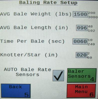
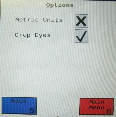
27 Baling Rate Setup After pushing the SETUP MODE key in the MAIN MENU screen, the top screen should appear: On this screen the operator will Select the BALING RATE SETUP key. 2. Select the number to the right of AVG Bale Weight (Lbs): to adjust the weight of your bales. The key pad shown will display. Select any number combination in this screen within the min/max limits. The information will remain until it is changed again. 3. Select the number to the right of AVG Bale Length (In): to adjust the length of your bales. Select any number combination in this screen within the min/max limits. The information will remain until it is changed again. 4. Select the number to the right of Time Per Bale (Sec): to adjust the time it takes to make a bale. Select any number combination in this screen within the min/max limits. The information will remain until it is changed again. 5. Select the number to the right of Knotter/Star to adjust the distance between the knotter and star wheel. To determine the distance, measure between the center of the starwheel and the center of the knotter. This is important so the job record correlates to the bale being made. 6. When the AUTO Bale Rate sensors are ON the applicator will calculate your tons per hour automatically. When the AUTO Bale Rate sensors are OFF a constant tons per hour (your inputed bale weight and time) will be used. Operating the unit with the AUTO Bale Rate sensors OFF will cause total tons per hour in Job Records to be left blank. Select the underlined word to toggle between ON or OFF. First Time and Annual Setup is checking with AUTO Bale Rate sensors OFF. 7. Selecting the Baler Sensors will allow you to use the Baler Sensor inputs in place of the standard applicator sensors if your baler is equiped with them from the factory. The sensors will come OFF as a default and the DCP will Reset to default when changed. If you choose to use the baler sensors be sure your baler is equipped with that option. For example, if you do not have an electronic bale length kit, turn that sensor OFF. The baler End of Row sensors are triggered once the PTO speed goes below 600RPM. The End of Bale sensor is triggered by the tie cycle alarm. The Bale Scale sensor is for the baler equiped with a Chute Scale. Note: Baling on rough terrain or hills can cause the scale to give an inaccurate reading. Turn Bale Scale option OFF in the Baler Sensor Screen and use AVG Bale Weight (2) reading as weight of bale. 8. Next select the Back key found on the bottom left hand of the screen to return to the SETUP MODE screen, or select the MAIN MENU key on the bottom right hand of the screen to return to the opening screen. 9. Select the OPTIONS key to adjust the system between metric and standard units. The Crop Eyes can also be turned ON or OFF in the OPTIONS screen. Select the ON/OFF next to Crop Eyes to change this setting. Note: If you change languages you may need to reset the system from the MAIN MENU screen. 27
. Manual Mode will apply preservative to the hay at a fixed rate regardless of the moisture content or baling rate.")
28 Operating Instructions Automatic Mode will automatically apply product based on both hay moisture content sensed by the star wheels and the operator s preset parameters. (See Setting Up System for Initial Use to change any of these settings). Manual Mode will apply preservative to the hay at a fixed rate regardless of the moisture content or baling rate. Automatic Mode After pushing the AUTOMATIC MODE key in the MAIN MENU screen, the following screen should appear: Push the Pause key (1) to stop application while in operation. 2. Push the Override key (2) to turn on all three pumps at the same time for full output of the system. Use this mode when going through a short area of wet crop. 3. The moisture content is shown in the upper right hand corner. 4. Baling Rate and Application Rate are shown in the middle. The operator sets the target application rate in the SETUP MODE. The ACTUAL rate should be within +/- one pound when running. The Baling Rate is also calculated in the SETUP MODE. 5. The totals on the bottom of the screen show the total Tons Baled and # Used (pounds of product used) for the current job. These numbers will reset to zero when a new Job Record is started. If operating with Bale Rate Sensors OFF total Tons Baled will be zero. 6. The graph shows the moisture trend from the past 90 seconds in 3 second intervals. 7. Last Bale shows the average moisture content for the last bale. 8. Any Status Alerts for the system will overlay the screen. Press the button to clear the Alert Message. See the Status Alerts section for information. 9. Press the MAIN MENU key to return to the opening screen. 28
 to stop application while in operation. 2. Push the Override key (2) to turn on all three pumps at the same time for full output of the system.")
29 Manual Mode After pushing the MANUAL MODE key in the MAIN MENU screen, the following screen should appear: Push the Pause key (1) to stop application while in operation. 2. Push the Override key (2) to turn on all three pumps at the same time for full output of the system. Use this mode when going through a short area of wet crop. 3. In MANUAL MODE you can turn the pumps ON or OFF by pressing the underlined area next to the pump numbers. In MANUAL MODE (regardless of moisture, tons per hour or bale weight) the outputs of the pumps are fixed rates as follows: Low output tips: Pump 1 = 60 LBS/HR Pump 2 = 100 LBS/HR Pump 3 = 150 LBS/HR High output tips: Pump 1 = 100 LBS/HR Pump 2 = 150 LBS/HR Pump 3 = 300 LBS/HR 4. The moisture content is shown in the upper right hand corner. 5. Baling rate and Application rate are shown in the middle. The output of a pump can be checked by dividing the preset output (shown in step 3) by the baling rate. For example, if you have the high output tips in and are running all three pumps, your output is 550 lbs/hr. Given the Baling Rate shown on the above screen (40.5 tons/hr), the application rate should be about 13.5 lbs/ton (550lbs/hr divided by 40.5 tons/hr). 6. The Totals at the bottom of the screen show the total Tons Baled and # Used (pounds of product used) for the current job. These numbers will reset to zero when a new Job Record is started. If operating with AUTO Bale Rate sensors OFF total tons baled will be zero. 7. The Baling Rate is set in the SETUP MODE menu. 8. The graph shows the moisture trend from the last 90 seconds of baling (one reading every 3 seconds). 9. Last Bale shows the average moisture content for the last bale. 10. Press the MAIN MENU key to return to the opening screen. 29
 followed by the time. When done select the OK key (2). NOTE: The clock uses military (or 24")
30 Diagnostics After pressing the DIAGNOSTICS key in the MAIN MENU screen, the screen on the left should appear: 1. To set date and time select the Set Date/Time (1) key. In the next screen enter the date (month, day, year format) followed by the time. When done select the OK key (2). NOTE: The clock uses military (or 24 hour) time. 2. Select the Software Versions key to check all software versions of modules attached to the Dual Channel Processor (DCP). The information will appear in the screen shown below right Press the MAIN MENU (4) key to return to the opening screen. 30


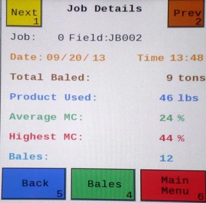
31 Job Records After pushing the JOB RECORDS key in the MAIN MENU screen, the upper left screen below should appear: Selecting New Job will save all the previous bale records and open the Field Name screen. 2. Use the key pad in the Field Name screen to enter up to an eight character field name. Use the asterisk key to move on to the next letter or number if they are identical. Use the pound sign as a space between the characters. When you have completed the field name press enter. 3. Pressing Job Details will open the Job Details screen. Use the Next and Prev icons to view the different jobs. Job: 0 will always be your current and open job record. Press Back to go to the Job Records screen or Main Menu for the main screen. 4. Selecting Bales at the center bottom of the screen will open a Bale Details screen. This screen lets you look at the individual bale records for the first five bales made. Use the Next and Prev icons to scroll through five bales at a time. Select Back to go to the Job Details screen or Main Menu for the main screen. Continued on the next page 31
 you would like to download using the Next and Prev icons to highlight the job(s).")

32 Continued Job Records 5. Selecting the Download key will open the Download Job Records screen. This screen lets you select jobs to download onto a USB drive. To download insert a USB drive into the port on the Dual Channel Processor. Select the job(s) you would like to download using the Next and Prev icons to highlight the job(s). Once the desired jobs are selected press the Download key. Press the Download key again to confirm. When the USB drive light goes off all the jobs selected will be saved. The jobs can then be opened on any computer with Excel or Notepad. To delete jobs highlight, select them and press Delete followed by pressing Delete again for confirmation. Press Back to go to the Job Records screen or Main Menu for the main screen. 6. Pressing the Select key will select or unselect the highlighted job. 7. Pressing the Select All key will select all jobs, except for the current job (0). To unselect press the Back key. 8. The job record in Excel will show as on the left above. The Bale ID column will need to be adjusted for proper viewing. 9. The job record in Notepad will show as on the right above. You will need to scroll right to see all the information. 32


33 Maintenance If you are unsure how to perform any of the maintenance steps have your local authorized dealer perform the tasks. Maintenance Schedule Daily 10 hrs 400 hrs Weekly Monthly Season Diagnostics X X Filter bowl cleaning X X Tips & tip screen cleaning X X Tank lid cleaning X X Dielectric grease connections X X Rebuild pumps X Battery connections X X Check valves X Visually inspect hoses X X Diagnostics: Follow the instructions in this manual to check Date and Version in the Diagnostics mode. Filter Bowl Cleaning: The filter bowl is located in front of the applicators tank and is connected to the ball valve. Before cleaning the filter bowl all personal protective equipment must be worn (Face shield or goggles, chemically resistant apron, boots, and gloves). Verify that the ball valve located next to the pump is turned off. Locate the filter bowl on the side of the pump manifold (A). Unscrew the bottom section of the filter bowl and remove the strainer. (B) Clean off any debris and soak in warm water with a mild soap if necessary. Once the screen is clean reinstall by following the directions in reverse. A B 33
.")
34 Tips and Tip Screen Cleaning: The spray shield assembly that holds the tips and tip screens is located above the pickup head. Before cleaning the tips and screens all personal protective equipment must be worn (Face shield or goggles, chemically resistant apron, boots, and gloves). Verify that the ball valve located next to the pump is turned off. Disconnect check valve nuts (A) and remove screens for cleaning (B). B A 34

35 Tank Lid Cleaning: Before cleaning the tank lid all personal protective equipment must be worn (Face shield or goggles, chemically resistant apron, boots, and gloves). The tank lid is located on the top of the tank. Use the supplied handle on the tank to secure your person and use the other hand to remove any debris from the top of the tank. Unscrew the tank lid and bring down ground level. Use compressed air clean out the tank breather (D). Once the breather is cleaned reinstall the cover. D Dielectric Grease Connections: Disconnect all harnesses on the applicator, clean the connections, and repack with dielectric grease. Rebuild Pumps: If Diagnostic or Manual mode show that the pumps are running lower than normal, a pump rebuild may be necessary. To do this rebuild the pump must be removed from the pump manifold. Pump rebuild is part no A service pack that includes pump rebuilds and check valves is available from your local dealer. Verify that the ball valve is turned off. Before working around the pumps all personal protective equipment must be worn (Face shield or goggles, chemically resistant apron, boots, and gloves). Remove pump from manifold. Follow rebuild instructions supplied with pump rebuild kit. Reinstall after rebuild is complete. Battery Connections: Follow the batteries safety warnings and clean the battery connections. If the connections cannot be cleaned, replace harness. Check Valves: Before servicing the check valves all personal protective equipment must be worn (Face shield or goggles, chemically resistant apron, boots, and gloves). Verify the ball valve is turned off before service the check valves. Replace the intake check valves by the pumps ( F) and the discharge check valves by the tip ( VB). Miscellaneous Maintenance: 1. Depending on the product being used, the system may need to be flushed with water at a regular interval (consult with manufacturer of the chemical.) If Harvest Tec product is being used, flushing is not necessary. 2. Although the pump can run dry, extended operation of a dry pump will increase wear. Watch the preservative level in the tank. 3. If you are using bacterial inoculants, flush your system daily after every use. 35
36 Winter Storage 1. Thoroughly flush the system with water. 2. Remove the filter bowl and run dry until the water has cleared out of the intake side. 3. Remove the red plug from the bottom of the pump, drain, and run the pump for 30 seconds or until it is dry. 4. Drain all lines on the outlet side. 5. Never use oils or alcohol based anti-freeze in the system. 6. For spring start-up, if the pump is frozen, turn off the power immediately to avoid burning the motor out or blowing a fuse. The pump head can be disassembled and freed or rebuilt in most cases. Check the fuses after the pump has been freed. 7. Disconnect power from the Precision Information Processor. 8. Remove display from tractor and store in a warm, dry place. Tip Selection Guide High Output Tips for Rates Requiring lbs/hr. (Approximately tons/hr) Red tips (Part #: 004-T8003-PT) Brown tips (Part #: 004-T80015-PT) Pink tips (Part #: 004-T8001-PT) --Blue Hose Pump 3 --Green Hose Pump 2 --Clear Hose Pump 1 Low Output Tips for Rates Requiring lbs/hr. (Approximately tons/hr) Brown tips (Part #: 004-T80015-PT) Pink tips (Part #: 004-T8001-PT) Silver tips (Part #: 004-T SS --Blue Hose Pump 3 --Green Hose Pump 2 --Clear Hose Pump 1 36
37 Wiring Diagram A. The Baler Power/Communication Harness ( LSE) will attach to the open port of the Tractor Harness ( TME) and run back to the Dual Channel Processor ( LS). Connect the large plug of the Baler Power/Communication Harness ( LS) to the bottom (shorter side) of the DCP. B. Attach the Baler Interface Harness ( VA) in between the short whip cable hardwired to the DCP and the main Power/Communication Harness ( LSE. Make sure Active Terminator removed from the top of the baler processor is attached to Baler Interface Harness ( VA). C. Install green terminator ( Z) to the port labeled Modular Port on the Pump Controller ( ). D. Attach moisture and bale rate harness ( HLE) as well as the end of bale harness ( BBEXT) to the DCP ( LS). E. Attach the Pump Control Harness ( F3M) between the Pump Controller ( ) and the DCP ( LS). F. Connect Keyed Power Extension harness ( K) to a keyed power source. G. Connect the Bluetooth Receiver ( A) to the Communication Harness ( TME). Note: The Optional Port and the Data Transfer Port are not used in this application. Star Wheel Assembly (2X) Proximity Sensor (2X) S Moisture/Bale Rate Harness HLE Dual Channel Processor (DCP) LS Data Transfer Flow Meter A End of Bale Sensor BB Extension for Bale Sensor BBEXT Pump Controller Optional Port Pump Harness Z Pump Controller Harness F3ME Bluetooth Receiver A Terminating Connector Z Active Terminator from Baler Harness Orange Wire to Keyed Power Keyed Power Extension K Baler Connection Baler Interface Harness VA Power/Comm Harness on Baler LSE Power/Comm Harness on Tractor TME 37


38 Pin Outs Power/Comm Harness TME at Hitch Pin 1 Red +12V Power to TSD Pin 2 Red +12V Power to DCP Pin 3 Orange Keyed Power Pin 4 Gray Shield Pin 5 Green HT Can Low Pin 6 Yellow HT Can Hi Pin 7 Orange Can1 Hi Pin 8 Black Ground from TSD Pin 9 Black Ground from DCP Pin 10 Blue Can1 Low Power/Comm Harness LSE at Hitch Pin 1 Red +12V Power to TSD Pin 2 Red +12V Power to DCP Pin 3 Orange Keyed Power Pin 4 Gray Shield Pin 5 Green HT Can Low Pin 6 Yellow HT Can Hi Pin 7 Orange Can1 Hi Pin 8 Black Ground from TSD Pin 9 Black Ground from DCP Pin 10 Blue Can1 Low Bluetooth Receiver on Harness TME Pin 1 Red +12V Power from DCP Pin 2 Black Ground from TSD Pin 3 Yellow HT Can Low Pin 4 Gray Shield Pin 5 Green HT Can Hi Pin 6 Orange Can1 Hi Pin 7 Blue Can1 Low VA to DCP Whip Pin 1 Red Can Power Pin 2 Black Can Ground Pin 3 Yellow HT Can Hi Pin 4 Gray Shield Pin 5 Green HT Can Low Pin 6 Orange Can1 Hi Pin 7 Blue Can1 Low 38


39 Pin Outs (continued) VA to LS Pin 1 Red Can Power Pin 2 Black Can Ground Pin 3 Yellow HT Can Hi Pin 4 Gray Shield Pin 5 Green HT Can Low Pin 6 N/A Pin 7 N/A VA Harness to Baler Plug Pin A N/A Pin B Red TBC Power Pin C N/A Pin D Gray TBC Ground Pin E Orange Can1 Hi Pin F Blue Can1 Low A D Main Power Connector on DCP Pin 1 Red +12V Power from tractor Pin 2 Black Ground from tractor Pin 3 Orange Keyed power Star Wheel and Bale Rate Sensor Connector on DCP Pin 1 Blue +12V Power Pin 2 Orange Ground Pin 3 Black Signal for sensor 1 Pin 4 White Signal for sensor 2 Pin 5 N/A Pin 6 N/A Pin 7 N/A Pin 8 Violet Star wheel input 1 Pin 9 Brown Star wheel input 2 End of Bale Sensor on DCP Pin 1 Brown Sensor Power Pin 2 Blue Sensor Ground Pin 3 N/A Pin 4 Black Signal from Sensor 39

40 Pin Outs (continued) Pump Communication Plug on DCP Pin 1 Red +12V Can Pin 2 Red +12V Power Pin 3 Gray Shield Pin 4 Green Comm Channel OH Pin 5 Yellow Comm Channel OL Pin 6 Blue Comm Channel IH Pin 7 Orange Comm Channel IL Pin 8 Black Can Ground Pin 9 Black Power Ground Pin 10 N/A Pump Connection Colors Pin 1 Black with Orange Stripe Pin 2 Black with Green Stripe Pin 3 Black with Yellow Stripe Pin 4 N/A Pin 5 Orange with Black Stripe Pin 6 Green with Black Stripe Pin 7 Yellow with Black Stripe Pump 1 Ground Pump 2 Ground Pump3 Ground Pump 1 Positive Pump 2 Positive Pump 3 Positive Flow Meter Connection on Pump Controller Pin 1 White +5-12V Power Pin 2 Green Ground Pin 3 Brown Signal Pin 4 Black Shield Connector for Crop Eyes on DCP Pin 1 Red +12V Power Pin 2 Black Ground Pin 3 White Signal Pin 4 N/A 40
41 Common Questions 1. How do I turn the system on/off? Turn the key in the tractor to the on position.. 2. How to get in the LBS/TON, MC%, and TONS/HR menus? In the Main Menu press the Setup Mode option. From this screen you can change your application rates and how much product is applied. See the section on Setting Up For Initial Use for a detailed explanation of this process. 3. The unit is stuck in the MC% screen. In the MC% screen, level 1 must be less than level 2, and level 2 must be less than level 3. For example, if level 1 is set at 16, level 2 must be set at 17 or higher, and level 3 must be set higher than level How does Override work? Override turns on all three pumps at full output. The pumps will remain at full output until the operator turns these pumps off by pressing the Override key again. 5. The flow meter reading is more or less than the programmed level set in the box. Some variation in flow meter readings compared to the programmed set point is normal due to factory tolerances on the pump motors as well as varying tractor voltages inputted to the control box. The flow meter reading is an accurate measure of how much product is actually being applied. The set points then will need to be adjusted if you want to attain a different flow meter reading. 6. Why don t all the pumps turn on even at higher application rates? The selections of what pumps turn on when are automatically controlled by the control box s flow rate look up chart. Thus, not all the pumps turn on at once and the combination of what pumps turn on when is automatically controlled by the software. 7. The moisture content displays LO or HI all the time. When the moisture content display does not change frequently while baling, there is likely a faulty star wheel connection. One of the first places to check is inside the white star wheel block. Check to see if the electronic swivel is in the star wheel shaft and check to see that the star wheel shaft is not working out of the block. Also, check all star wheel wires and connectors to see if there is a continuity or grounding problem. 8. Should the battery connections be removed before jump starting or charging a battery? Yes. Anytime the tractor will have voltage going up rapidly the connections should be removed. 9. How can I turn the optional hay indicators Crop Eyes On/Off from the cab? From the Setup Mode screen press Options. Press the On/Off underlined area next to Crop Eyes. 10. Bale scale does not give a consistent reading. Baling on rough terrain or hills can cause the scale to give an inaccurate reading. Turn Bale Scale option OFF in the Baler Sensors Screen and use AVG Bale Weight reading as weight of bale. 41
42 Troubleshooting Problem Possible cause Solution Pump will not run. 1. No voltage to DCP or Pump 1. Check for short, low voltage, and controller. replace fuse(s) if necessary. 2. Pump locked up. 2. Clean or rebuild pump if motor is OK. 3. Damaged wire. 3. Repair damaged wire. 4. Fuse blown on Pump controller. 4. Replace fuse and check pump for short in wire or locked motor. Pump runs but will not prime. 1. Air leak in intake. 1. Tighten fittings on intake side. 2. Clogged intake. 2. Clean. 3. Restricted outlet. 3. Check and clean tips. 4. Check valve on the outlet is stuck closed. 4. Clean or repair check valve. 5. Dirt inside pump. 5. Replace pump check valve. Pump does not develop enough output. 1. Air leaks or clogs on inlet side. 1. Tighten or clean filter bowl assembly. 2. Pump worn or dirty. 2. Rebuild pump. Moisture reading errors (high or low) Moisture readings erratic. Flow meter readings do not match up with product usage. Product is less than actual product used. Product shown is more than actual product used. 1. Wire disconnected or bad connection between star wheels and DCP 2. Low power supply to DCP 3. Wet hay over 75% moisture 4. Ground contact with one or both star wheels and baler mounted processor. 5. Short in wire between star wheels and DCP. 6. Check hay with hand tester to verify. 1. Test bales with hand tester to verify that cab monitor has more variation than hand tester. 2. Check all wiring connections for corrosion or poor contact. 3. Check power supply at tractor. Voltage should be constant between 12 and 14 volts. 1. Voltage supplied to meter is less than 6 volts. 2. Wiring short in signal to baler mounted processor. 3. Clog in meter. 4. Using product other than Harvest Tec 1. High voltage supplied to the meter. 2. Light interference with meter. 3. Air leak in intake. 4. Using product other than Harvest Tec Reconnect wire. 2. Check voltage at box. (Min of 12 volts required.) See Diagnostics section of manual. 4. Reconnect. 5. Replace wire. 6. Contact Harvest Tec if conditions persist. 2. Apply dielectric grease to all connections. 3. Install voltage surge protection on tractors alternator. 1. Check for a min of 6 volts supplied at Pump controller. 2. Inspect wire and replace if necessary. 3. Back flush with water. DO NOT USE AIR. 4. Catch and weigh product to check outputs. 1. Check voltage at Pump controller. Max of 18 volts. 2. Reflection into meter can cause a high reading. Move meter or protect from sunlight. 3. Look for air bubbles in line. Replace line or other defective area that is allowing air into the system. 4. Catch and weigh product to check outputs.
43 System leaks product out of tips after shut down. Terminal reads under or over power. System does not pause at end of row when using 474A crop eyes. Bale rate displays zero. Display says PAC error Bale scale not giving accurate reading Can t select moisture / preservative information on baler run screen Blue Tag / Nozzle icon flashing on baler run screen Warning: HT system type conflicts with machine setup? or --- for moisture values are being shown on baler run screen Job records are showing as symbols or incorrect values Values in auto / manual mode are obscure Can t download job records, stuck at Saving to USB Stick Can t download job records, stuck at Searching No green baler sensors button in bale rate setup screen Bale rate goes to zero and prox sensors/star wheels check out fine Cannot open USB message when trying to download 1. Dirty or defective check valves. 1. Clean or Replace. 1. Verify with multi-meter actual voltage. Voltage range should be between volts. 1. Short in cable. 2. Damaged sensor. 3. Bad alignment of sensors 1. Bale rate sensors are reversed. 2. Short in cable. 3. Damaged sensor. 1. The DCP and Pump controller are not communicating. 2. Broke connection between the display and DCP or Pump control and DCP. Load cell calibration is off DCP not selected in baler software CNH ECU is set to communicate with DCP, but DCP is not communicating correctly with baler CNH Baler ECU recognizes that a Harvest Tec system is installed, but system is not configured correctly. CNH software must see a stuffer cycle before it will update the moisture values The job file is corrupted on SD card The job file is corrupted on SD card One of more jobs are corrupted on SD card. If saving to USB is displayed, some jobs have been downloaded correctly. If searching is displayed then the first job is corrupted and download will not work. DCP is not configured to communicate with baler DCP is set to use Bale Rate Sensor from baler in calculation and baler does not have this option installed DCP does not see a USB stick in the Data Transfer port 1. Clean connections and make sure applicator is hooked to battery. See Diagnostics section of manual. 1. Replace cable. 2. Replace sensor 3. Check 474 manual for alignment instructions 1. Switch the sensors next to the star wheel. 2. Replace cable. 3. Replace sensor. 1. Check all connections at DCP and Pump controller including terminating resistors. 2. Check, clean, and tighten connections. 1. Refer to your scale owner s manual for instructions on recalibrating. Select DCP for the moisture option in machine setup. See Communicating through ISOBUS Monitor section in operation manual DCP has to be reconfigured. Contact your dealership to send back to Harvest Tec for repair. DCP has to be reconfigured. Contact your dealership to send back to Harvest Tec for repair. Simulate a stuffer cycle on baler, or wait until baling in the field and the moisture will update Write down all job record information the operator wishes to keep. Update the DCP software to the most current version available on the Harvest Tec website. Delete all existing jobs by selecting all in the download screen and pressing delete. Be sure to start a new job an verify it is saved by checking job details screen. If baler is compatible, Harvest Tec can reconfigure DCP to correct setting. Contact your dealership to send back to Harvest Tec for repair. Turn off Bale Rate Sensor in baler sensors screen, make sure Auto baling rate is turned on in baling rate setup screen Make sure the operator has the USB in the DCP with good connect and not the VT port in the cab of the tractor. 43


44 Parts Breakdown Parts Breakdown for Tank, Saddle and Saddle Legs Ref Description Part Number Qty Ref Description Part Number Qty 1 Tank Right saddle leg MR 1 2 1/2" tank fitting /2" hose Elbow 003-EL NP Elbow 003-EL Tank straps P 2 NP Elbow 003-EL Tank saddle N 1 NP ¾ Tank fitting Handrail HR 1 7 Tank lid H 1 Optional: 8 Left saddle leg ML 1 NP Tank lid strainer HBS 1 44

45 Parts Breakdown for Pump Manifold c 4 12b 5 12a Ref# Description Part Number Qty 1 Pump plate D 1 2 Mounting Bracket C 1 3 Pump H 3 4 Street elbow fitting 003-SE Nipple fitting 003-M Check valve F 3 7 Elbow fitting 003-EL Tee fitting 003-T3812HB 2 9 Flow meter assembly A 1 10 Straight fitting 003-A Jaco fitting 003-JEL Filter bowl assembly a Filter bowl only F 1 12b Filter bowl gasket D 1 12c Filter bowl screen A 1 13 Nipple fitting 003-M Ball valve Street elbow fitting 003-SE Hose clamp Hose clamp (Flow Meter) Pump Cable Z 1 NP Elbow 003-EL NP Pump rebuild kit (1 per pump) NP Not Pictured 45

 w/006-4641k 2 holes in it 7. Plug fitting 003-F38 2 1-10 Star wheel assembly 030-4641 2 8.")
46 Star Wheel Moisture Sensor and Bale Rate Sensors Ref Description Part Number Qty Ref Description Part Number Qty 1. Block cover B 2 9. Star wheel block A 2 2. Electronic swivel A Star wheel sensor C 2 3. Swivel insert w/ Ref # Twine guard-left Snap ring (per side) K 2 Twine guard-right (prox) Washer (per side) w/ k 2 And with bale rate sensor 6. Dust seal (per side) w/ k 2 holes in it 7. Plug fitting 003-F Star wheel assembly Wiring grommet A 2 12 Ref Description Part Number Qty 12 Bale rate sensor S 2 13 Moisture and bale rate harness HLE
 002-9016 25ft 7 Female 002-2204A 1 Three hose assembly 002-9016B 002-9016G 030-9016LS 25ft 25ft 1")

47 Parts Breakdown for Hose and Drain Fill Line Ref Description Part Number Qty Ref Description Part Number Qty 1 Triple weld hose (pumps to tips) ft 7 Female A 1 Three hose assembly B G LS 25ft 25ft 1 Coupler 2 1/2 Hose (tank to filter) ft 8 Male Coupler G 1 3 3/4 Hose (tank to drain/fill valve) ft 9 Valve Holder H 1 4 Straight Fitting 003-A Ball valve Elbow 003-EL Jiffy Clip Hose Clamps


48 Parts Breakdown for 697BB Series Controls and Harnesses Dual Channel Processor (DCP) Ref Description Part Number Qty 1 EOB Extension for CNH BB Series BBEXT 1 2 Terminating Connector 600 Series Z 1 3 End of Bale Sensor Bracket End of Bale Sensor 600 Series DCP Shield/Cover X 1 6 DCP Main Control LS 600 AUTO LS 1 7 Pump Controller Key Switch Wire K 1 9 DCP Baler ISO/VT Harness VA 1 10 DCP Tractor Harness TME 1 11 Modular Power/Comm 20 FT Harness F3ME 1 12 Dust Plugs PLUGS 1 13 DCP Baler Harness 15 FT LS 1 Bluetooth Receiver Part #: A 48


 20 Leg Ext-Short Chamber 001-6707MX 2 (Included in 4532B")
49 Harvest Tec Model 4532B, 4533B and 4534B Installation Kits (4534B has longer EVA tubes between Manifold Blocks) Ref Description Part Number Qty Ref Description Part Number Qty 1 Holder NCX 1 11 Cap Shield NSX 1 12 Fitting 003-A1414VB 3 3 Fitting 003-F Strainer Manifold Block NSB 2 14 Check Valve VB 3 5 Lynch Pin Fitting 003-A1414F 3 6 Tip-Red 004-T8003-PT 2 16 Clear Tubing-1/ ft 7 Tip-Brown 004-T80015-PT 2 17 Blue Stripe Tubing B 3 ft 8 Tip-Pink 004-T8001-PT 2 18 Green Stripe Tubing G 3 ft 9 Tip-Stainless 004-T SS 2 19 EVA-1/ * ft 10 Hose Clamp (*330 & LB334 use 1 ft, *340 & LB434 use 3 ft) 20 Leg Ext-Short Chamber MX 2 (Included in 4532B Kits Only) 20 49

50 Harvest Tec Model 4535B and 4536B Installation Kit (4536B has longer EVA tubes between Manifold Blocks) 1 Ref Description Part Number Qty Ref Description Part Number Qty 1 Holder NC 1 11 Cap Shield NSX 1 12 Fitting 003-A1414VB 3 3 Fitting 003-F Strainer Manifold Block NSB 2 14 Check Valve VB 3 5 Lynch Pin Fitting 003-A1414F 3 6 Tip-Red 004-T8003-PT 2 16 Clear Tubing-1/ ft 7 Tip-Brown 004-T80015-PT 2 17 Blue Stripe Tubing B 3 ft 8 Tip-Pink 004-T8001-PT 2 18 Green Stripe Tubing G 3 ft 9 Tip-Stainless 004-T SS 2 19 EVA-1/ * ft 10 Hose Clamp *330 & LB334 use 1 ft *340 & LB434 use 3 ft 50
51 Optional ipad Mini Mounting Kit ( MK) Ref Description Part # Qty 1 Suction cup mount SCM 1 2 Ram mount H 1 3 ipad Mini spring load cradle (Mini 1,2,3) SLC gauge power wire P 1 5 Female spade connector Hardware 2 6 Eye loop connector Hardware 2 7 ipad Mini Charger 12V P 1 8 ipad Mini 2 case C2 1 NP 4 amp fuse Hardware 1 Mounting Kit Assembly MK (Includes All Parts) Installation Instructions 1. Identify 12V power source for wires to connect. a. Eye loops included if wiring directly to the battery is desired. b. Test for key power source if preferred to have power to the USB shut off with the key. 2. Once power source is identified, cut wires to desired length. 3. Crimp the two supplied quick connectors onto each the white and black wire. 4. Remove the round locking plastic nut from USB plug before connecting the wires. Black (+) White (-). 5. The wires will then be hooked to the designated terminals on the bottom of the USB plug 6. Drill a 1 1/8 hole in the preferred mounting location. Be sure to clean any sharp edges after drilling. 7. Feed the wires through the mounting hole. 8. If using the round plastic nut to secure plug in place, slide the nut back over the wiring before connecting the wires to powered source. 9. Connect the wires to the identified power source if easier to do so before tightening the plug into place. 10. Tighten plug using either the round plastic nut or mounting plate and two screws, both options supplied. 11. Once connected, hook a USB charging cord into the plug and connect a mobile device/tablet to ensure the plug is operating as you wish (key power working properly if necessary). NOTE: This plug is not designed to charge two ipads. System damage could occur if this is attempted. System will charge a mobile phone and ipad simultaneously without problem. 51
 001-2012SLC 1 9 ipad Mini 2 006-2670IP 1 4 16 gauge power wire 006-4723P -1 NP 4 amp fuse Hardware 1 5 Female")
52 Optional ipad Display Kit ( DK) Ref Description Part # Qty Ref Description Part # Qty 1 Suction cup mount SCM 1 7 ipad Mini Charger 12V P 1 2 Ram mount H 1 8 ipad Mini 2 case C2 1 3 ipad Mini spring load cradle (Mini 1,2,3) SLC 1 9 ipad Mini IP gauge power wire P -1 NP 4 amp fuse Hardware 1 5 Female spade connector Hardware 2 6 Eye loop connector Hardware 2 Mounting Kit Assembly DK (Includes All Parts) Installation Instructions 12. Identify 12V power source for wires to connect. a. Eye loops included if wiring directly to the battery is desired. b. Test for key power source if preferred to have power to the USB shut off with the key. 13. Once power source is identified, cut wires to desired length. 14. Crimp the two supplied quick connectors onto the white and black wire. 15. Remove the round locking plastic nut from USB plug before connecting the wires. Black (+) White (-). 16. The wires will then be hooked to the designated terminals on the bottom of the USB plug 17. Drill a 1 1/8 hole in the preferred mounting location. Be sure to clean any sharp edges after drilling. 18. Feed the wires through the mounting hole. 19. If using the round plastic nut to secure plug in place, slide the nut back over the wiring before connecting the wires to powered source. 20. Connect the wires to the identified power source if easier to do so before tightening the plug into place. 21. Tighten plug using either the round plastic nut or mounting plate and two screws, both options supplied. 22. Once connected, hook a USB charging cord into the plug and connect a mobile device/tablet to ensure the plug is operating as you wish (key power working properly if necessary). NOTE: This plug is not designed to charge two ipads. System damage could occur if this is attempted. System will charge a mobile phone and ipad simultaneously without problem. 52
Operation Manual. Model 600BB. Moisture Sensor Kit for Large Square Balers For New Holland BigBaler and Case IH LB BB-OPR 5/14
 Operation Manual Model 600BB Moisture Sensor Kit for Large Square Balers For New Holland BigBaler and Case IH LB 4 010-0600BB-OPR 5/14 (intentionally blank) 2 Harvest Tec Model 600BB Operation Table of
Operation Manual. Round Baler Models. 25 & 55 gallon Preservative Applicators 437T-446T-447T-447CT-447UT-449T-15-OPR 8/16
 Operation Manual Round Baler Models 5 & 55 gallon Preservative Applicators 47T-446T-447T-447CT-447UT-449T-5-OPR 8/6 (Intentionally blank) Round Baler Models Operation Table of Contents Page Introduction
Installation Manual. Model 600A1. Moisture Sensor Kit for Large Square Balers 600A1-15-INST 2/15
 Installation Manual Model 600A1 Moisture Sensor Kit for Large Square Balers 600A1-15-INST 2/15 DECLARATION OF APPLICATION OF ESSENTIAL REQUIREMENTS OF THE DIRECTIVE 2006/42/ EC OF THE EUROPEAN PARLIAMENT
H2O Sensor - Model 200
 Owner s Manual H2O Sensor - Model 200 Round Baler Precision Moisture Sensing Kit H 2O Sensor-Owners-18-Imp&Metric 12/18 DECLARATION OF INCORPORATION MANUFACTURER: Harvest Tec Inc. 2821 Harvey St. P.O.
A John Deere Allied Supplier. Hay Preservative and Applicator Systems for Hay Balers. Equipment and Products for Quality Hay. TM.
 Equipment and Products for Quality Hay. TM A John Deere Allied Supplier Hay Preservative and Applicator Systems for Hay Balers Applicators Moisture Sensors Automatic Controls Hay Preservative Harvest Tec
2012 Toolbar & NH3 Operators Manual
 2012 Toolbar & NH3 Operators Manual P/N 320379 Amity Technology, LLC 2800 7th Avenue North Fargo, ND 58102 (701) 232-4199 www.amitytech.com This Page Left Intentionally Blank Page 2 2012 Toolbar/NH3 Manual
LOUP II DRILL MONITOR OPERATION MANUAL. SOFTWARE v45
 LOUP II DRILL MONITOR OPERATION MANUAL SOFTWARE v45 Service and Technical Support Contact: Loup Electronics Inc. Address: 2960 N. 38th Street Lincoln, NE 68504 Phone: 877-489-LOUP(5687) 402-464-7131 Fax:
Halton SAFE / 7.14 user guide and installation instructions
 Halton SAFE / 7.14 user guide and installation instructions VERIFIED SOLUTIONS BY H A LTO N Enabling Wellbeing Table of contents 1 System description 3 2 User Accounts 4 3 Main menu 7 3.1 Main menu - Change
1592 In Cab Monitor (ICM) QUICK START GUIDE
 QUICK START GUIDE") 1592 In Cab Monitor (ICM) QUICK START GUIDE Refer to your Operators Manual for additional information on controls 89-023 Rev - C 4/2013 Program # 1592.0.45.3 SAFETY Allied Systems Co. is concerned with
1592 In Cab Monitor (ICM) QUICK START GUIDE Refer to your Operators Manual for additional information on controls 89-023 Rev - C 4/2013 Program # 1592.0.45.3 SAFETY Allied Systems Co. is concerned with
i.c³ User Guide For Helmer i.series Ultra-Low Freezers A/A
 i.c³ User Guide For Helmer i.series Ultra-Low Freezers 360175-A/A Document History Revision Date CO Supersession Revision Description A 18 APR 2014* 9275 n/a Initial release. * Date submitted or change
Freeman 1592 Baler Operating System Manual
 Freeman 1592 Baler Operating System Manual The following pages detail how to use the 1592 Big Baler Control Monitor. Read entire manual before operating baler. Consult operator s manual for more information,
HAYBOSS G2 BALER EQUIPMENT FROM MASSEY FERGUSON
 HAYBOSS G2 BALER EQUIPMENT FROM MASSEY FERGUSON 2 www.masseyferguson.com Page 6 Moisture Monitor Page 8 Bale traceability Page 9 600 Series Automatic Applicator Contents. 3 Baling quality forage 4 Baler
Operators Manual. E15 Seeder Console Air Seeder Monitor A600 R1.3 V2.0.18
 Operators Manual E15 Seeder Console Air Seeder Monitor A600 R1.3 V2.0.18 How to use this operators manual As with any software operated equipment, software and/or hardware is in many cases changed and
OPERATOR S MANUAL. Safety Notices... 1 Disclaimer... 1
 Safety Notices... 1 Disclaimer... 1 System Components... 3 Features... 3 Virtual Terminal (VT)... 3 Cab Harness Connection to 12 Virtual Terminal... 4 Cab Harness Connection to 10 Virtual Terminal... 5
THX-DL Data Logger USER & INSTALLATION MANUAL V
 THX-DL Data Logger USER & INSTALLATION MANUAL V1.2012 www.thermomax-refrigeration.com Contents PRESENTATION Summary of Features 2 INSTALLATION Safety Precautions 4 THX Unit 4 Sensors 4 Alarm Relay 4 Power
347002K/177002K/34900
 Service Manual Models: 347002K/177002K 34900/347012K Manifold Block Style Recovery/Recycling/Recharging Unit For R-12 or R-134a Only TABLE OF CONTENTS: Theory of Operation and Safety Precautions... 2 Depressurizing
Products documentation (REVISION DATE: 03/10/2011) OMFP6010 (60cm PIROLITIC OVEN)
 OMFP6010 (60cm PIROLITIC OVEN)") Products documentation (REVISION DATE: 03/10/2011) OMFP6010 (60cm PIROLITIC OVEN) Ovens Service Manual Models OMFP6010 CONTENTS This document has been published to be used for service only. The contents
Products documentation (REVISION DATE: 03/10/2011) OMFP6010 (60cm PIROLITIC OVEN) Ovens Service Manual Models OMFP6010 CONTENTS This document has been published to be used for service only. The contents
DEMA 832 LAUNDRY MASTER TM INSTALLATION INSTRUCTIONS
 System Overview DEMA 832 LAUNDRY MASTER TM INSTALLATION INSTRUCTIONS The DEMA 832 Laundry Master is designed for long reliable use with simplicity in mind for both the installer and user. The system is
Safety. Rinse Kit for Multi-Pro 1200 and 1250 Turf Sprayers Model No Safety and Instructional Decals. Installation Instructions
 Rinse Kit for Multi-Pro 1200 and 1250 Turf Sprayers Model No. 106-4842 Form No. 3353-529 Rev B Installation Instructions Note: Determine the left and right sides of the machine from the normal operating
OPERATING MANUAL. for the modular heat presses. Secabo TC5 SMART and TC7 SMART
 OPERATING MANUAL for the modular heat presses Secabo TC5 SMART and TC7 SMART Congratulations on the purchase of your Secabo heat press! Please read this operating manual carefully to ensure a smooth production
Operating & Maintenance Manual. Alert-4 Ethernet LCD Master Alarm
 Operating & Maintenance Manual Alert-4 Ethernet LCD Master Alarm w w w. a m i c o. c o m Contents User Responsibility 4 Introduction 4 Features 5 Description of the Alarm 5 Shipment Details 5 The Alarm
THE GENUINE CHOICE BALER ACCESSORIES
 THE GENUINE CHOICE BALER ACCESSORIES BALER ACCESSORIES If you want consistently high output and superior bales, you need the right equipment. The Massey Ferguson 2200 Series large square baler is not
HP727S. Single speed swimming pool heat pump controller Operation manual TABLE OF CONTENTS
 HP727S Single speed swimming pool heat pump controller Operation manual TABLE OF CONTENTS 1. General Description 2. Specifications 3. Installation Instructions 4. Electrical Wiring 5. Instrument Wiring
CONTROL PANEL INTERFACE ACTIVATE THE GENERATOR DISPLAY INTERFACE MENUS. Control Panel USING THE AUTO/OFF/MANUAL SWITCH
 CONTROL PANEL INTERFACE USING THE AUTO/OFF/MANUAL SWITCH With the switch set to AUTO, the engine may crank and start at any time without warning. Such automatic starting occurs when utility power source
Skyport Wi-Fi Installation for the ColorTouch in 5 Easy Steps
 Skyport Wi-Fi Installation for the ColorTouch in 5 Easy Steps Secure Internet Connection Computer Update ColorTouch to firmware version 2.0 or higher* Install the Wi-Fi Key and connect to a local router
For Quick Set-Up go to Page 14
 Talking Thermostat Model VT3000 Guide SmartWay Solutions, Inc. US Patent 6,608,560 & 7,62,253 For Quick Set-Up go to Page 4 Model VT3000, a universal thermostat for use on most Gas or Electric, Conventional
OPERATION AND MAINTENANCE MANUAL ELC-810 AUTOMATIC WATER LEVEL CONTROLLER. AquatiControl Technology
 OPERATION AND MAINTENANCE MANUAL ELC-810 AUTOMATIC WATER LEVEL CONTROLLER AquatiControl Technology 3820 South Federal Blvd Sheridan, Colorado 80110 Toll Free: 877.755.8817 Fax: 303.761.1499 www.aquaticontrol.com
INSTRUCTION MANUAL 4-WAY BALL VALVE Digital Manifold
 LOW VAC INSTRUCTION MANUAL 4-WAY BALL VALVE Digital Manifold REF HIGH SPECIAL FEATURES Low battery indicator Displays 63 refrigerants Displays corresponding saturation, dew or bubble point temperature
USER MANUAL SPRAY GUN CLEANER - WATER BASED PAINTS UA400W CAUTION FOR WATER BORNE PAINTS ONLY
 USER MANUAL SPRAY GUN CLEANER - WATER BASED PAINTS UA400W CAUTION FOR WATER BORNE PAINTS ONLY THIS UNIT IS NOT DESIGNED FOR USE WITH SOLVENT BASED PAINT UNI-RAM CORPORATION ONTARIO CANADA REV 2010-09 CONTENTS
Quick Setup Guide for IntelliAg Model NTA607HD
 STEP 1: Pre-Programming Preparation: STEP 3: Row Status/Row Width Setup Press Row I/O button. Enter desired values using Table A as reference. Press Work Screen button to return to the Main Work screen.
Page 1 of 18. Part# /5/2013
 Part# 1002655-06 8/5/2013 This manual contains important information concerning the installation and operation of the gun washers listed above. Read manual thoroughly and keep for future reference INSTRUCTIONS
INSTALLATION AND OPERATION INSTRUCTIONS LC-D SERIES COFFEE CONCENTRATE BREWER WITH DIGITAL ELECTRONIC CONTROL CENTER
 107353 1-00 INSTALLATION AND OPERATION INSTRUCTIONS LC-D SERIES COFFEE CONCENTRATE BREWER WITH DIGITAL ELECTRONIC CONTROL CENTER PLUMBER'S INSTALLATION INSTRUCTIONS CAUTION: Power to brewer must be OFF
VCM-X / RNE Controller Operator Interface SD Technical Guide
 VCM-X / RNE Controller Operator Interface SD Technical Guide VCM-X Controller Code: SS1026 VCM-X E-BUS Controller Codes: SS1030, SS1032, SS1033, SS1034 RNE Controller Code: SS1045 VAV/Zone Controller Code:
Syringe Pump. User Manual
 Syringe Pump User Manual Specifications Length Height Width Weight Waterproof Rating Battery 30 cm 13 cm 12.5 cm 1.8 kg IPX3 Rechargeable Li Polymer 7.4 V 1900 mah 6 Hour Battery Life Running 3 Hours When
NexSysLink. 2 CAN Display Operation Manual. CAN Instruments Product Family
 NexSysLink CAN Instruments Product Family 2 CAN Display Operation Manual Contact Beede Beede Electrical Instrument Company, Inc. 88 Village Street Penacook, NH 03303 (603) 753-6362 Toll-free 800-451-8255
HEDMAN DI-50. Endorser Instructions. Hedman DI-50 Operators Guide
 HEDMAN DI-50 Endorser Instructions Hedman DI-50 Operators Guide 25-0132-20 TABLE OF CONTENTS 1. INTRODUCTION...1 1.1 DI-50 Description...1 1.2 Items Included...1 1.3 Safety Terms...2 1.4 Safety Precautions...3
Explorer F210 Fuel Instrument Installation and Operation Manual
 Explorer F210 Fuel Instrument Installation and Operation Manual www.northstarnav.com 2 Northstar Explorer F210 Installation and Operation Manual IMPORTANT SAFETY INFORMATION Please read carefully before
1 and 2 Fan Vision Series Portable Dryers
 1 and 2 Fan Vision Series Portable Dryers Operator s Manual PNEG-1456 Date: 09-29-09 PNEG-1456 2 PNEG-1456 1 and 2 Fan Vision Series Portable Dryers Table of Contents Contents Chapter 1 Safety... 5 Safety
OWNER S MANUAL. Models: Herkules Equipment Corporation 2760 Ridgeway Court Walled Lake, MI USA Fax
 Part# 1000692 7/12/99 tn INSTRUCTIONS This manual contains important information concerning the installation and operation of the gun washers listed at the right. Read manual thoroughly and keep for future
INSTALLATION INSTRUCTIONS
 TT-1343 5/06b INSTALLATION INSTRUCTIONS Original Issue Date: 8/03 Model: Automatic Transfer Switches Equipped with Series 1000 Programmable Controller Market: ATS Subject: Remote Annunciator Kits GM28938-KP1,
DEMA 844 Laundry Master Laundry Chemical Dispensing
 DEMA 844 Laundry Master Laundry Chemical Dispensing Overview The DEMA Laundry Master is a digital laundry dispenser designed to dispense chemicals when signals are received from commercial laundry machines.
Emerson Inspire 1HDEZ Installation Instructions. Thermostat/Interface Equipment Control TROUBLESHOOTING
 Emerson Inspire 1HDEZ-1521 Installation Instructions Thermostat/Interface Equipment Control TROUBLESHOOTING FAILURE TO READ AND FOLLOW ALL INSTRUCTIONS CAREFULLY BEFORE INSTALLING OR OPERATING THIS CONTROL
D3000. Installation & Setup Guide
 Page 1 of 15 17483-00 Rev B s1 April 2009 Contents Description Page Safety... 3 Installation Standards 3 Specification. 3-4 Circuit Board Connection 5 Mounting Dimensions 6 Installation Procedure 6 Mechanical
Read all instructions & warnings before using this product. Keep this manual for future reference. Warnings. Parts & Accessories
 INSTRUCTION MANUAL INDEX Read all instructions & warnings before using this product. Keep this manual for future reference. Introduction Warnings Setup Operation PC Application Calibration Maintenance
Introduction. Disclaimer. Application. EasySplicer components
 USERS MANUAL 1 Table of contents Introduction... 3 Disclaimer... 3 Application... 3 EasySplicer components... 3 Basics... 4 Quick Start... 4 Turn on the EasySplicer... 4 Start with a Calibration... 4 Singlemode
IMAGE V. Parts and Service Manual
 IMAGE 0V Section II Parts and Service Manual (88B) CLARKE TECHNOLOGY Image Operator's Manual Page AUTHORIZED PERSONNEL MAINTENANCE To Access Pump Motor. Remove brush housing from machine. See "Brush Motor
JCM Products Quick Reference Guide
 JCM Products Quick Reference Guide ivizion Units NOTE: Due to advancements in related industry technologies and future product development, the information in this guide is subject to change without notice.
Chem-Trak Jr. Instruction Manual
 Chem-Trak Jr. Instruction Manual 0900590 Rev: B (02/10) Page 1 of 40 TABLE OF CONTENTS Specifications... 3 System Overview... 4 Operation... 5 Installation... 6 SIB and Interrupt Modules... 8 Wiring Diagram...
FLOW METER KIT #
 FLOW METER KIT #80495684 2 General information This manual contains technical information regarding Bayer SeedGrowth Equipment. Please read and understand these instructions completely before proceeding
Operating, Installation and Service Manual W3400H, CLC 41 Clarus Control
 Operating, Installation and Service Manual W3400H, CLC 41 Clarus Control 438 9202-01 05.26 Washer extractor, drum volume 400 litres 3 Contents Machine operation... 7 General description... 7 Automatic
TS400. Operating Manual. Test Station for Microtector II Series (G450/G460)
") Operating Manual TS400 Test Station for Microtector II Series (G450/G460) GfG GESELLSCHAFT FÜR GERÄTEBAU MBH KLÖNNESTRASSE 99 44143 DORTMUND, Germany TEL. +49 / (0)2 31 / 5 64 00 0 FAX +49 / (0)2 31 /
Operating Manual TS400 Test Station for Microtector II Series (G450/G460) GfG GESELLSCHAFT FÜR GERÄTEBAU MBH KLÖNNESTRASSE 99 44143 DORTMUND, Germany TEL. +49 / (0)2 31 / 5 64 00 0 FAX +49 / (0)2 31 /
FIRERAY 5000 range USER GUIDE
 FIRERAY 5000 range USER GUIDE 0044-003-04 IMPORTANT PLEASE NOTE: The beam path MUST be kept clear of obstructions at all times! Failure to comply may result in the Detector initiating a Fire or Fault signal.
EDR Series. Model. Instruction Manual. Rev 5.0. Thank you for purchasing the EDR Auto Smart.
 EDR Series Model Instruction Manual Rev 5.0 Thank you for purchasing the EDR Auto Smart. Please read this Instruction Manual thoroughly before using this machine. Please carefully read and thoroughly understand
Models: GW/R-T GW/R-2-T GW/R-3-T
 Part# GW/R-T-OM 1/12/04 TN Models: GW/R-T GW/R-2-T GW/R-3-T This manual contains important information concerning the installation and operation of the gun washers listed above. Read manual thoroughly
HT-2 / 9600 Series Control Contents
 HT-2 / 9600 Series Control Contents Tools & Parts Tools Required Parts Required Error Messages 3 Flashing Dots Pressure or Flow Switch Not Activated Pressure or Flow Switch Activated Temperature Sensor
GENERATOR SELF-TEST VERIFIER (GSV300) INSTALLATION INSTRUCTIONS
 INSTALLATION INSTRUCTIONS") GENERATOR SELF-TEST VERIFIER (GSV300) INSTALLATION INSTRUCTIONS Page 1 GSV300 Installation Manual Rev XC INTRODUCTION The GSV300 is an easy to use, multifunction generator monitor that is packed with useful
GENERATOR SELF-TEST VERIFIER (GSV300) INSTALLATION INSTRUCTIONS Page 1 GSV300 Installation Manual Rev XC INTRODUCTION The GSV300 is an easy to use, multifunction generator monitor that is packed with useful
Using the Lely Robot Sampler CanWest DHI Robot Manual
 Using the Lely Robot Sampler 4 Lely Check List First time start-up settings done? Is sampler level? Is milk line connected through sampling valve? Is air pressure to the shuttle correct? Are there enough
RC-90 / RC-90B Single Stage Heat/Cool Thermostat for Zone Control Systems Installation Instructions
 RC-90 / RC-90B Single Stage Heat/Cool Thermostat for Zone Control Systems Installation Instructions DESCRIPTION The RC-90 is a precision digital thermostat designed for 24 VAC single stage heating and
Section 9 System Operation
 Section 9 System Operation Operation of the control panel is simple. Menus guide you step-by-step through operations. This section of the manual is an overview of the operation menus. Please read this
Operations Manual TS400. Test Station for G450/G460 Gas Detector
 TS400 Test Station for G450/G460 Gas Detector Operations Manual 1194 Oak Valley Dr, Ste 20, Ann Arbor MI 48108 USA (800) 959-0329 (734) 769-0573 www.goodforgas.com GfG Products for Increased Safety Congratulations
CBT LW MAINTENANCE GUIDE
 CBT LW MAINTENANCE GUIDE PICTOGRAMS Each Signifier displayed here is specific to this User Manual. Menu Previous Advance Note Tip Example Powder Feeder Mixing Bowl Weigh Scale CBP Tanks Control Panel PSD
prestige Control Application Supplement - ACVMax
 2015-10 Prestige ACVMax Control Sup 12-14-15_ACVMax_Control 12/15/15 7:36 AM Page 1 prestige Control Application Supplement - ACVMax L I S T E D WARNING This document is intended to be used by a factory
Dryer Controller M720
 User Manual Dryer Controller M720 Hardware version 2.00 Software version 2.00 Manual M720 Dryer controller Page 1 of 60 Document history Preliminary version: - Created in April, 2009 Hardware Version 2.00,
IMR IX176 Portable Gas Detector User Manual
 IMR Portable Gas Detector User Manual Read this manual carefully before using this device. (727) 328-2818 / (800) RING-IMR Fax: (727) 328-2826 www.imrusa.com Ver. 1.0A4 CONTENTS SERVICE GUIDELINES... 3
HP50HA ABG Heat Pump
 HP50HA ABG Heat Pump Troubleshooting Guide Residential TSG-ABGHPa Copyright 2017 Hayward Industries Inc. Safety Precautions Warning! High Voltage Electrocution Hazard Hazardous voltage can shock, burn,
Refrigeration Controller Operator s Manual (HRC) PO Box 6183 Kennewick, WA
 PO Box 6183 Kennewick, WA") Refrigeration Controller Operator s Manual (HRC) PO Box 6183 Kennewick, WA 99336 www.jmcvr.com 1-509-586-9893 Table of Contents TABLE OF FIGURES...1 OVERVIEW OF THE HRC CAPABILITIES...2 INSTALLATION AND
Refrigeration Controller Operator s Manual (HRC) PO Box 6183 Kennewick, WA 99336 www.jmcvr.com 1-509-586-9893 Table of Contents TABLE OF FIGURES...1 OVERVIEW OF THE HRC CAPABILITIES...2 INSTALLATION AND
OPERATOR'S MANUAL. IMPORTANT: READ OPERATOR'S MANUAL CAREFULLY Please fill out & return your warranty card! DP80405
 CARBON SPOT 30 EXTRACTOR OPERATOR'S MANUAL IMPORTANT: READ OPERATOR'S MANUAL CAREFULLY Please fill out & return your warranty card! DP80405 Diamond Products www.diamondproductsus.com Printed in the U.S.A.
Owner s Manual. Keep with machine for reference PKC24 INSTALLATION & OPERATION REV Perlick Corporation 8300 W Good Hope Rd Milwaukee, WI 53223
 Owner s Manual Keep with machine for reference PKC24 INSTALLATION & OPERATION REV.11.09 Perlick Corporation 8300 W Good Hope Rd Milwaukee, WI 53223 800-558- 5592 FAX 414-353- 7069 perlick.com TABLE OF
3500 SERIES CONVECTION STEAM COOKER PARTS AND SERVICE MANUAL
 3500 SERIES CONVECTION STEAM COOKER PARTS AND SERVICE MANUAL EFFECTIVE JULY 30, 2014 Superseding All Previous Parts Lists. The Company reserves the right to make substitution in the event that items specified
Flood Pumper Plus. Water Transfer Machine. Operator and Parts Manual. Model No.: Rev. 00 (11-99)
") Flood Pumper Plus Water Transfer Machine Model No.: 607841 Operator and Parts Manual NOBLES 12875 RANSOM STREET HOLLAND MI 49424 U.S.A. CUSTOMER SERVICE: 1-800-365-6625 FAX: 1 800 678 4240 608468 Rev.
Flood Pumper Plus Water Transfer Machine Model No.: 607841 Operator and Parts Manual NOBLES 12875 RANSOM STREET HOLLAND MI 49424 U.S.A. CUSTOMER SERVICE: 1-800-365-6625 FAX: 1 800 678 4240 608468 Rev.
DEMA 813 PROBELESS DEMAMaster TM INSTALLATION INSTRUCTIONS
 DEMA 813 PROBELESS DEMAMaster TM INSTALLATION INSTRUCTIONS Models: DM-813-PLLL-1T DM-813-PDLL-1T DM-813-PLLL-2T DM-813-PDLL-2T I-729 Pg 1 of 15 System Overview The DEMA DEMAMaster probeless series is designed
CAUTION UM120W (RIGHT TANK) FOR WATER BORNE PAINTS ONLY UM120W (RIGHT TANK) SECTION IS NOT DESIGNED FOR USE WITH SOLVENT BASED PAINT
 FOR WATER BORNE PAINTS ONLY UM120W (RIGHT TANK) SECTION IS NOT DESIGNED FOR USE WITH SOLVENT BASED PAINT") OPERATING MANUAL SOLVENT AND WATER BASE SPRAY GUN CLEANER UG5000W and UG5500W CAUTION UM120W (RIGHT TANK) FOR WATER BORNE PAINTS ONLY UM120W (RIGHT TANK) SECTION IS NOT DESIGNED FOR USE WITH SOLVENT BASED
OPERATING MANUAL SOLVENT AND WATER BASE SPRAY GUN CLEANER UG5000W and UG5500W CAUTION UM120W (RIGHT TANK) FOR WATER BORNE PAINTS ONLY UM120W (RIGHT TANK) SECTION IS NOT DESIGNED FOR USE WITH SOLVENT BASED
Product Guide. Ceiling PIR HS presence detector DALI / DSI dimming. PIR Sensor. IR Receiver. Light Level Sensor. Status LEDs.
 PPAD-C-HB-DALI-230V Product Guide Ceiling PIR HS presence detector DALI / DSI dimming Overview The PPAD-C-HB-DALI-230V PIR (passive infrared) presence detector provides automatic control of lighting loads
C F AQ S C85183 FAQS AC Power Batteries Atomic Alarm Clock Factory Restart Atomic Alarm Clock AC Power Batteries Explanation:
 C85183 FAQS The links below will work in most PDF viewers and link to the topic area by clicking the link. We recommend Adobe Reader version 10 or greater available at: http://get.adobe.com/reader CONTENTS
High Precision Digital Rain Gauge with Indoor Temperature and Humidity
 High Precision Digital Rain Gauge with Indoor Temperature and Humidity Contents 1. Introduction... 2 2. Get Started... 2 2.1 Parts List... 2 2.2 Recommend Tools... 3 2.3 Installation... 3 2.4 Mount outdoor
Spa Touch Control Panel with BP2100, BP6013 spa controllers. (Spa Owner s Manual insert)
") Spa Touch Control Panel with BP2100, BP6013 spa controllers. (Spa Owner s Manual insert) P.N. 7876C (export) February 12, 2015 For Spas equipped with BP2100, BP6013 controllers and Spa Touch panel. Spa
Spa Touch Control Panel with BP2100, BP6013 spa controllers. (Spa Owner s Manual insert) P.N. 7876C (export) February 12, 2015 For Spas equipped with BP2100, BP6013 controllers and Spa Touch panel. Spa
Refrigerated Incubator Model and Operating Instructions
 Refrigerated Incubator Model 165000 and 165000-2 Operating Instructions N2400379 - Rev. 1 08May2018 1 Contents 1. SAFETY...3 1.1. EMF INTERFERENCE...4 1. PRODUCT INFORMATION...5 1.1 INTRODUCTION...5 2.
Instruction Manual. Please read this manual and the Safety Instructions carefully before using your refrigerator.
 Nexberg Pty Ltd T/a Evakool 16 Enterprise St CALOUNDRA QLD 4551 Tel : 07 5492 7777 Fax : 07 5492 7733 Please read this manual and the Safety Instructions carefully before using your refrigerator. 1. Safety
CAUTION. Installation Manual
 System Controller SC-301-6M CAUTION Installation Manual In order to use this product safely, read this installation manual carefully and follow the installation instructions. Potential dangers from accidents
Table of Contents 1. OVERVIEW SYSTEM LAYOUT SPECIFICATIONS FUNCTION... 11
 Table of Contents 1. OVERVIEW... 3 2. SYSTEM LAYOUT... 4 3. SPECIFICATIONS... 8 3.1 SYSTEM COMPONENTS...9 3.2 PLC INPUTS AND OUTPUTS...9 3.3 FUNCTION KEYS...10 3.4 DEFAULT SET POINTS AND TIMERS...10 4.
Spa Touch Control Panel with 2000, 2100 controllers. (Spa Owner s Manual insert)
") Spa Touch Control Panel with 2000, 2100 controllers (Spa Owner s Manual insert) P.N. 7876B February 11, 2015 For Spas equipped with BP2000, BP2100 controllers and Spa Touch panel. Spa Touch Control Panel
Spa Touch Control Panel with 2000, 2100 controllers (Spa Owner s Manual insert) P.N. 7876B February 11, 2015 For Spas equipped with BP2000, BP2100 controllers and Spa Touch panel. Spa Touch Control Panel
EBC20. Instructions for fitting, installation and operation. Read and save these instructions!
 EBC20 UK Instructions for fitting, installation and operation Read and save these instructions! 2 3002878 EBC20 UK 290415 1. Product information............................................... 4 1.1 Delivery.............................................................
User Manual. Digi-Sense TC9500 Advanced Multiparameter Temperature Controller with Thermocouple, Thermistor, and RTD Inputs
 User Manual Digi-Sense TC9500 Advanced Multiparameter Temperature Controller with Thermocouple, Thermistor, and RTD Inputs Models 89800-03 and 89800-04 THE STANDARD IN PRECISION MEASUREMENT Table of Contents
X64 Wireless Training
 X64 Wireless Training IDS Contents 1 Contents Features 3 Wireless Hardware 4 IDS & Duevi integration PCB 5 LED operation 5 Wireless Device Hardware setup 6 Location 260 7 LED Keypad Instructions 7 Adding
Monitor Alarms and Events
 This chapter contains the following topics: What Are Alarms and Events?, page 1 How are Alarms and Events Created and Updated?, page 2 Find and View Alarms, page 3 Set Alarm and Event Management Preferences,
Installation, Operation & Maintenance Manual. Wash System
 Installation, Operation & Maintenance Manual Wash System Kleen Flo Wash System Installation, Operation & Maintenance Manual CONTENTS Introduction and Overview... 3 Pipeline Wash System Features... 5 Wash
Servicing manual. 600 Series - 11S / 19S / 24S / 24C. Wall-mounted condensing gas boiler. For trade use
 GB122 Servicing manual Wall-mounted condensing gas boiler 600 Series - 11S / 19S / 24S / 24C For trade use Please read thoroughly before attemting to diagnose fault 7217 4900 (03/2010) GB/IE List of contents
OWNER S MANUAL DLFCAB / DLFCHB / DLFDAB / DLFDHB High Wall Ductless System Sizes 09 36
 OWNER S MANUAL DLFCAB / DLFCHB / DLFDAB / DLFDHB High Wall Ductless System Sizes 09 36 TABLE OF CONTENTS PAGE SAFETY PRECAUTIONS... 2 GENERAL... 2 INDOOR UNIT PART NAMES... 3 REMOTE CONTROL PART NAMES...
OPERATING MANUAL SOLVENT SPRAY GUN CLEANERS UG5000E, UG5000DVM AND UG5500E UNI-RAM CORPORATION ONTARIO CANADA PATENTS
 OPERATING MANUAL SOLVENT SPRAY GUN CLEANERS UG5000E, UG5000DVM AND UG5500E PATENTS USA 4,788,836 CANADA USA 5,213,117 ENGLAND EUROPE 0300248 ITALY SWEDEN 0300248 GERMANY FRANCE 8110528.0 JAPAN UNI-RAM
TWLC - Tempered Water Logic Controller. The Intelligent Control
 TWLC - Tempered Water Logic Controller The Intelligent Control Chiller Controls Features: Up to six (6) stages: individual board for each stage maximizes redundancy. Menu driven access and programming.
Servicing manual. Wall-mounted condensing gas boiler 600 Series - 11S / 19S / 24S / 24C /2002 GB(EN) For trade use
 For trade use") GB122 7210 1300-12/2002 GB(EN) For trade use Servicing manual Wall-mounted condensing gas boiler 600 Series - 11S / 19S / 24S / 24C Please read thoroughly before attempting to diagnose fault List of contents
GB122 7210 1300-12/2002 GB(EN) For trade use Servicing manual Wall-mounted condensing gas boiler 600 Series - 11S / 19S / 24S / 24C Please read thoroughly before attempting to diagnose fault List of contents
DryLINK TRAINING Phoenix DryMAX XL and DryLINK
 DryLINK TRAINING Phoenix DryMAX XL and DryLINK FREE MOBILE APP 125 PPD XL LGR DEHUMIDIFIER WITH BLUETOOTH BE EVERYWHERE AT ONCE TABLE OF CONTENTS Introduction...3 Initial Setup Downloading the App...4
PRO 2000i LOW LEVEL DEPOSITOR
 DEPOSITORS AND AUTOMATED CAKE PRODUCTION SYSTEMS PRO 2000i LOW LEVEL DEPOSITOR OPERATION AND SPARE PARTS MANUAL Serial No. PR2L- (Please quote this number when ordering spares, and making service calls)
User Manual. Dryer Controller M720
 User Manual Dryer Controller M720 Hardware version 1.00 Software version 1.00 Preliminary version Manual M720 Dryer controller Page 1 of 42 Document history Preliminary version: - Created in April, 2009
Tempered Water Logic Control OPERATION l TROUBLE SHOOTING
 Tempered Water Logic Control OPERATION l TROUBLE SHOOTING English For MPE Multiple Chiller Units Control Panel TEMPERED WATER SYSTEMS L-2199 Rev. 20080223 Revision: L-2199 20101104 *** IMPORTANT NOTICE
Fast Track Troubleshooting
 Fast Track Troubleshooting Publication # rswf241 Revision Date 12/20/2011 Model: WF241ANW IMPORTANT SAFETY NOTICE For Technicians Only This service data sheet is intended for use by persons having electrical,
PRO Installation. Touch Wi-Fi Thermostat
 PRO Installation Touch Wi-Fi Thermostat 1 Designed by the pros for the pros There are a lot of choices when it comes to buying a thermostat, but only one combines 125 years of experience and the latest
Touchpad Exit Controller Administration Guide
 Touchpad Exit Controller Administration Guide 2018 RF Technologies, Inc. All specifications subject to change without notice. All Rights Reserved. No Part of this work may be reproduced or copied in any
Quick start guide. English
 Quick start guide English Read your entire Astral User Guide or Clinical Guide before use. The Astral device 1. Adapter port Can be fitted with single limb adapter, single limb leak adapter or double limb