AUTOMATIC IN-FLOOR CLEANING & CIRCULATING SYSTEM
|
|
|
- Andrew Holland
- 5 years ago
- Views:
Transcription
1 AUTOMATIC IN-FLOOR CLEANING & CIRCULATING SYSTEM INSTALLATION MANUAL MADE IN USA U.S. Patent No.: 4,188,673, 4,212,088, 4,391,005, 4,592,379 5,265,631, 6,301,723, 6,311,728, 6,314,999, 6,360,767 6,367,098, 6,393,629, 6,601,244, 6,810,537, 7,089,607, 7,178,179, Other Patents Pending REV East Corporate Place Suite 100 Chandler, AZ Toll Free: Phone: Fax:
2 FORWARD The Paramount Cyclean IN-FLOOR CLEANING SYSTEM is the culmination of years of extensive testing and engineering which provides your customers with the most advanced and trouble-free system available. The information contained in this manual is intended to answer some of the most common questions associated with the installation of the System. We urge you to take time to review it thoroughly. If you have any questions call Toll Free or visit IMPORTANT NOTICE The Paramount In-Floor Systems and other optional Paramount products are protected patented products and the methods and installation of said products are patented. An installer of these products must be trained and licensed by Paramount. This manual and documents contained within have been copyrighted and any reproductions are illegal without the written permission of Paramount Pool and Spa Systems.
3 TABLE OF CONTENTS DESIGN AND LAYOUT PRINCIPLE OF OPERATION BENEFITS OF THE SYSTEM SURFACE RETURNS PROPER NOZZLE PLACEMENT PUMP REQUIREMENTS FILTER REQUIREMENTS MULTIPLE SKIMMERS EQUIPMENT LAYOUT PLUMBING DETAIL PLUMBING (FLOOR) PLUMBING WATER VALVE VALVE CIRCUIT LAYOUT HEATERS IN-DECK CANISTER PRESSURE TEST POOL DRAIN SYSTEM RAISED SPAS NOZZLE PLACEMENT SPAS PLUMBING DETAIL RISER NOZZLE PLACEMENT STEPS STEEL DETAIL CONCRETE DETAIL PRE-PLASTER DETAIL BODY INSTALLATION POOL/SYSTEM START-UP TEST PLUGS, BASKETS & LIDS VALVE INSTALLATION PARAMOUNT MODULE ALIGNMENT GUIDE CLEANING NOZZLE INSTALLATION NOZZLE AND BODY DIAGRAM WINTERIZING TROUBLE-SHOOTING NOTES
4 DESIGN & LAYOUT PRINCIPLE OF OPERATION The CYCLEAN IN-FLOOR SYSTEM cleans by injecting pressurized water through a series of nozzles located throughout the pool. The pressurized water flow keeps dirt in suspension for removal by the pool filtration system, an active main drain, a skimmer, and an optional in-deck debris canister. The water flow is directed to various cleaning nozzles in a sequential manner by Paramount's patented water-actuated distributor valve. The flow is constant and lasts for approximately 60 seconds. When the flow stops, the nozzle will retract and rotate slightly to a new position so that when it is energized again it will clean a different portion of the pool. BENEFITS OF THE SYSTEM Reduction in chemical costs due to enhanced water circulation Reduced electrical costs due to reduced pump time due to increased water circulation Reduction of heating costs Elimination of unsightly devices Lifetime warranty and replacement under warranty conditions of cleaning nozzles Elimination of large leaves and debris with one of Paramount s patented optional VGB Compliant Debris Drains and Debris Containment Canister BRUSHING IS NOT COMPLETELY ELIMINATED. Although the system GREATLY reduces the time and cost of maintaining a pool, it DOES NOT ELIMINATE the need to: MAINTAIN A PROPER CHEMICAL BALANCE BRUSH THE POOL PERIODICALLY CLEAN BASKETS AND FILTERS ON A REGULAR BASIS In conclusion, the IN-FLOOR SYSTEM is not a 100% cleaner and should never be presented as such. 1
5 DESIGN & LAYOUT SURFACE RETURNS Surface returns used in conjunction with the IN-FLOOR SYSTEM are a builder's option. If all six ports of the water valve are not required, the use of surface returns (particularly in areas with excessive surface debris) is highly recommended. If all six ports of the water valve are utilized for the floor, steps and/or spa, and automatic surface returns are desired, we recommend a separate pump and filter. Another option is to oversize the pump and plumb a manual return. The flow through the manual return would have to be regulated in order to ensure adequate flow through the floor system. Surface returns are also advisable in shallow "game" pools. They enable people to use the pool and have the filtration system operating without the possibility of stepping on the cleaning nozzles. PROPER NOZZLE PLACEMENT Proper nozzle placement is the single most important item in making the SYSTEM clean properly. As a general rule, one head is required for each 60 square feet of surface area (in pebble - 50 sq. ft.). Pools with breaks and free form pools will generally require two (2) additional nozzles. This formula does not include nozzles required for steps and benches. The exact total cannot be determined until a scaled drawing has been made and nozzles have been properly placed. NOZZLE PLACEMENT CRITERIA 1. 6' RADIUS CLEANING IN PLASTER, 5'6 IN PEBBLE 2. DISTANCE FROM VERTICAL SURFACES (WALL OR STEP) MINIMUM 2' - MAXIMUM 3 ½'. 3. MAXIMUM DISTANCE FROM CORNER (4 FEET). 4. ALL AREAS MUST INTERSECT OR OVERLAP. NOTE: Calculations based on a 1' radius dig in the shallow end and a 5' radius in the deep end (assuming maximum depth of 4' shallow and 9' deep.) 2
 E.")

6 DESIGN & LAYOUT NOZZLE PLACEMENT STEP 1 - DRAW POOL SHAPE (FIG FIG. 1.4) A scaled drawing of the pool must be made including the following details: A. Outline of pool shape B. All steps, benches, offsets, etc. C. Normal main drain location D. Break or transition point between shallow and deep end (if applicable) E. Any other items that may affect the water flow from the nozzles - i.e., in pool umbrella or tables F. Water line on zero entry beach entries Use either 1/8 in. = 1 ft. scale or ¼ in. = 1 ft scale Use either 1mm = 100mm scale or 1mm = 50mm scale Fill out a cover sheet and fax with drawing to Paramount and we will layout your pool cleaning system. How to submit plans cad@1paramount.com (scalable electronic files.dxf,.dwg) 2. Fax Distances In Fee Pool Spa Booster Pump for Cleaning Syste PoolAnd Spa AreConnected Solar Heate Pool Floo Steps Benches Spa Basin Skimmer Quantity: Pool Depths S A M P L E HP: (CompletingthissectionwillresultinanOrderbeingprocess e Tpe - 04 Tanzanite

7 DESIGN & LAYOUT DIMENSIONED NOZZLE PLACEMENT DRAWING After the nozzle placement has been determined, a scaled drawing will be made with dimensions clearly indicated. The dimensioned drawing should be the plumber's guide and a part of the superintendent's check sheet to insure proper placement. As stated earlier, proper nozzle location is critical. Should the pool's configuration change (i.e., step location, break location, overall dimension) the nozzle placement must also change. A revised plan must be drawn. Choose one nozzle to use as a starting point and indicate dimensions to outer walls. This will enable the plumbers to find location of first nozzle and then use triangulation to locate the remaining ones. The sequencing order, from a cleaning aspect, is immaterial. Since the cleaning nozzles operate on a random principle, the need for sequencing is eliminated. However, sequencing from shallow to deep is recommended for ease of plumbing, installation and trouble-shooting. S A M P L E 4
8 DESIGN & LAYOUT PUMP REQUIREMENTS Selecting Proper Pump Size 1. Determine GPM and Ft./Hd. requirements from Specification Chart below. 2. Refer to manufacturer's pump curve of equipment you use. 3. Compare Part # and Model #. Do not rely on horsepower. Most manufacturers make both full-rated and up-rated pumps. This also relates to low and high service factors. 4. Most pump curves will show Total Head in Feet on the left side vertically. Gallons per Minute are indicated horizontally across the page. 5. Draw an X where the two lines intersect. This will give you the pump required. In-floor System Specification Chart SINGLE PUMP *60 80 TDH or *40 60 TDH Filter/ Cleaner Pump MIN. FILTER 4.9 Sand 48 Sq.Ft. D.E. 200 Sq.Ft. Cart. DUAL PUMP *40 60 TDH or *60 60 TDH Cleaner Pump MIN. FILTER 3.1 Sand 36 Sq.Ft. D.E. 200 Sq.Ft. Cart. No Multi-Port Filter Valves Bypass On Heater Size Filter Pump to pool turnover. Multi-Port OK. No Bypass On Heater Required * Any time the equipment is more than 50 ft. away from skimmer, special engineering is required. Submit a copy of the proposed plan indicating the specific information to Paramount Pool & Spa Systems. * G PM stated are the requirements of the in-floor system. Additional equipment such as chlorine generators, spa overflows, etc., require more water flow. Adjust pump G PM requirements accordingly. 5
9 DESIGN & LAYOUT FILTER REQUIREMENTS Selecting Proper Filter Size When selecting filter sizes, if the filter requirements fall in between available sizes, select the next larger filter. Refer to Equipment Spec Chart for required rate. Diatomaceous Earth (D.E.) D.E. filters are rated at 2 GPM per square foot of filter area. Sand Sand filters are rated at 20 GPM per square foot. 1-1/2" MULTI-PORT VALVES ARE NOT RECOMMENDED BECAUSE HEAD LOSS IS GREATLY INCREASED. PARAMOUNT RECOMMENDS THE USE OF 2" PUSH/PULL OR 2" MULTI-PORT VALVES ON SINGLE PUMP SYSTEMS. NOTE: Filter rates in excess of 20 GPM per sq. ft. can cause channeling of the filter bed. Cartridge Cartridge filters are rated at.25 GPM per square foot of filter area. NOTE: Excess flow rates can cause the fibers of a cartridge to become impacted. 1-1/2" MULTI-PORT VALVES ARE NOT RECOMMENDED BECAUSE HEAD LOSS IS GREATLY INCREASED. PARAMOUNT RECOMMENDS THE USE OF 2" PUSH/PULL OR 2" MULTI-PORT VALVES ON SINGLE PUMP SYSTEMS. 6
10 DESIGN & LAYOUT IMPORTANT TECHNICAL NOTICE REGARDING MULTIPLE SKIMMERS AND CLEANING EFFICIENCIES The usage of more than one skimmer with any In-Floor systems may create conditions where the main drain and skimmers are not effective. This is particularly true with Paramount s line of VGB Compliant Debris Drains. When the pool incorporates a single pump design with up to a 2 hp (2-1/2 hp up rated) pump and an In-Floor system, the maximum flow of water through the hydraulic system is only GPM. The Paramount optional VGB Compliant Debris Drains require 35 GPM to operate properly. The remaining suction flow is through the skimmer. When a second skimmer is added, the flow then becomes reduced. Having only GPM over a skimmer weir is not effective. Traditionally, consumers adjust the skimmers to effectively pull water and surface debris and thus reduce the suction upon the main drain. We have found that with an In-Floor system the best rule of thumb is "One skimmer and one main drain with a one pump system". On pools over 500 sq. ft., we recommend the design include a two-pump system. Because of the energy savings, faster clean up and less stringent equipment requirements, multiple skimmers may be incorporated. The second pump may be plumbed with the filter pump to share a single skimmer which, in effect, super-charges the skimmer. Alternatively, the second pump may be plumbed to a second skimmer. This design allows both skimmers to separately draw a minimum 35 GPM and the main drain to effectively operate as designed. 7
11 DESIGN & LAYOUT EQUIPMENT LAYOUT Single Pump Dual Pump SECOND SKIMMER (optional) CANISTER 8


12 PLUMBING DETAIL PLUMBING (FLOOR) Install the SYSTEM with required feed lines from the water valve to banks of heads containing two or more nozzles each. The feed lines are 2" Schedule 40 PVC pipe. Paramount recommends that the lines enter at the center of length of pool. Excavate a niche to the bottom of the pool depth at that location. This large niche allows ample room for the feed lines. Generally, this will provide for the least amount of pipe. There are occasions when it may be advantageous to feed part of the lines in places other than the center. At each nozzle location, install a 2" elbow with 2" Schedule 40 PVC stubbed up 12" above the finished pool floor (except for steps and benches). Step and bench nozzles should be on a separate port. The number of nozzles per port in the floor should be constant whenever possible. All pipes should have a minimum of 2" of cover. Trenches should be backfilled and raked smooth. Paramount recommends soaking and tamping the ground after backfilling the trenches. It is imperative that the stub-up angle is 90 degrees to the finished floor angle. This must be verified and adjusted prior to placing gunite or concrete shell. Paramount recommends use of the primer on all joints underground. Cap all lines and pressure test to a minimum of 35 psi. Install the pressure-test stack at the equipment header or on one of the stub-up pipes in the pool floor. Pressure should remain on system throughout construction. 9
13 PLUMBING DETAIL PLUMBING (WATER VALVE) 2" VALVE BASE PLUMBING GUIDE NOTICE: All pipe fittings MUST be staggered. (See pictures next page) All plumbing should be 2". The water valve is normally set 6" above water level in a convenient location poolside. This results in dramatic reduction in plumbing runs and increased cost savings. The center port of the bottom housing is the inlet to the valve. Cut all pipes square, this allows maximum gluing surface to the bottom housing. USE PVC PRIMER AND PVC GLUE ON BOTTOM HOUSING AND ON PVC PIPES. (IPS WELDON P68 PRIMER and 711 GLUE or 705 GLUE or EQUIVALENT) Glue pipe all the way into the stop and allow at least 24 hours drying time before pressure test. To prevent glue damage to internal ribs always glue with the valve right side up. If not all six (6) ports are required, use one of the ports twice to feed one return line. The common ports should not be plumbed next to each other, always skip a port when double firing. The pipes from the water valve should be connected together underground. 1. Remove Clamp 2. Lift off dome (save 0-ring) 3. Remove pressure gauge and knob from inside valve housing assembly. 4. Primer valve base two times 5. Make sure pipes are glued all the way into the stop. Be careful not to allow glue to run into module area.* 6. The center port is the inlet to the valve and should be approximately 3" longer than the perimeter pipes. 7. Allow 24 hour before pressure testing. GLUING INSTRUCTIONS 8. Reposition o-ring in groove in the valve base. 9. Replace dome and V-Clamp and tighten until snug. 10. Thread the pressure gauge to the top of the dome. DO NOT USE TEFLON TAPE 11. Pressurize with pool plumbing (do not exceed 35 psi.) 12. Store the module assembly in a safe place and install after the pool has been started up. * Pipes should be a minimum of 12" in length and should insure the valve be at least 6" above water level. 10
 2\"X12\" PVC PIPE (port 2,4,6) (3) 2\"X15\" PVC PIPE (port 1,3,5) (1) 2\"X18\" PVC PIPE (port inlet) (4) 2\"X2 1/4\" PVC PIPE (port 1,2,5,6) (11) 2\" SLIP 90 ELBOWS")

14 PLUMBING DETAIL PLUMBING (WATER VALVE) 2" VALVE BASE PLUMBING GUIDE NOTICE: All pipe fittings MUST be staggered. PARTS NEEDED FOR ASSEMBLY OPTION ONE (3) 2"X12" PVC PIPE (port 2,4,6) (3) 2"X15" PVC PIPE (port 1,3,5) (1) 2"X18" PVC PIPE (port inlet) (4) 2"X2 1/4" PVC PIPE (port 1,2,5,6) (11) 2" SLIP 90 ELBOWS Optional: replace (4) 90 elbows and (4) 2"x2 ¼" pipes with (4) spigot 90 elbows Set in trench 15"deep X 19" wide Stagger 3" min. NOTE: Height of riser pipes may be adjusted as long as the 3" height differential between fittings is maintained. OPTION TWO (2) 2"X12" PVC PIPE (port 3,6) (2) 2"X15" PVC PIPE (port 2,4) (2) 2"X18" PVC PIPE (port 1,5) (1) 2"X21" PVC PIPE (port inlet) (2) 2"X2 1/4" PVC PIPE (port 6) (8) 2" SLIP 90 elbows Optional: replace (2) 90 elbows and (2) 2 x2 ¼" pipes with (2) spigot 90 elbows (port 6) Set in trench 19" deep X 12" wide IMPORTANT: PORT 1 AND 5 MUST BE SET AT 15 OFF CENTER- LINE IN ORDER TO CLEAR 11

15 6 CIRCUIT PLUMBING DETAIL VALVE CIRCUIT LAYOUT 9 CIRCUIT CIRCUIT
16 PLUMBING DETAIL FROM SKIMMER BALANCING VALVE FROM MAIN DRAIN PUMP BALANCING VALVE FILTER BACKWASHING VALVE CHECK VALVE CHECK VALVE 1 BYPASS LINE WATER VALVE HEATER IMPORTANT MANUAL 1 BYPASS LINE HEATERS When installing a heater on the pool, a 1" BY-PASS TO PARTIALLY DIRECT WATER AROUND THE HEATER IS NECESSARY. This allows part of the water through the heater for heating but limits the head loss created when all the water is directed through the heater. THE IN-FLOOR SYSTEM WILL NOT FUNCTION PROPERLY WITHOUT THIS BY-PASS. SOLAR SYSTEMS Paramount recommends solar systems be operated independently with a booster pump, separate suction, and returns, or as shown below with a secondary booster pump, and the in-floor system valve installed after the solar and heater pack. COLLECTOR PANELS SOLAR SENSOR VACUUM BREAKER IN-LINE BOOSTER PUMP CHECK VALVE RETURNS HEATER FILTER POOL PUMP CLEANING SYSTEM POOL SYSTEM HEAT PUMP Heat pumps must have a minimum by-pass of 1 ½ with a gate valve for adjustment. The gate valve must be set with a temperature probe to factory specs for heat rise. 1 1/2 INCH GATE VALVE 13

17 PLUMBING DETAIL IN-DECK CANISTER REQUIREMENTS Single Pump System Dual Pump System In-deck Debris Trap 14


18 PLUMBING DETAIL PRESSURE TEST DETAIL TO VENT LINE Notice: Release pressure on the system before removing plugs System Design: NOTICE: WARNING: The drain used must be installed in accordance with the manufacturer s written instruction manual, and in conformity with applicable Federal, State, Local and Swimming pool industry building and safety codes. If you use one of the Paramount MDX VGB Compliant Debris Drains consult the applicable manual for specific instruction on how to plumb. MANUAL PART NUMBERS: MDX-R3 Non Adjustable Concrete: MDX-R3 Adjustable Concrete: MDX² Concrete: POOL DRAIN SYSTEM 15
19 PLUMBING DETAIL RAISED SPAS AN IN-LINE CHECK VALVE IS REQUIRED IN ALL RAISED SPAS. PLUMB THE CHECK VALVE ABOVE GROUND FOR EASE OF FUTURE MAINTENANCE. NOZZLE PLACEMENT - SPAS Keep in mind that if cleaning nozzles in the spa are part of the cleaning cycle of the swimming pool, consideration must be given to the additional water being injected into the spa. This water must be removed via dam wall overflow, equalizer line, etc. When plumbing a spa, it is recommended the nozzles be on a separate port of their own. NOTE: Separate line with check valve required on raised water features or spas. WATER VALVE WATERLINE SPRING CHECK VALVE SPA POOL 16
20 PLUMBING DETAIL PLUMBING FOR FLOOR NOZZLES 2 SCH. 40 PIPE, 15 LONG 1 BY 1 CUTOUT AROUND THE PIPE FOR WATER STOP CONCRETE CUT PIPE HERE SOIL 2 ELBOW 2 PIPE NOTE: All risers must be 90 degrees (perpendicular) to the finished floor 17

21 PLUMBING DETAIL NOZZLE PLACEMENT (STEPS / BENCHES / SWIM-OUTS) 1. Using a 5 radius, indicate location of step-cleaning nozzle. A. B. C. D. NOTE: Each nozzle will not clean more than 5 radius on steps or benches. 2. Nozzles should be pulled out as far as possible in order to reach corners. Heads 2 from tread edge Radius Corners CORRECT INCORRECT 3. Reversed radius* of step corners will help to eliminate dirty steps. * This will also help with the floor cleaning where the bottom step meets the pool wall. 18


22 STEEL DETAIL REBAR MUST BE KEPT AWAY FROM 2" PVC RISER. REBAR SHOULD BE BENT AROUND RISER SO THAT STEEL IS MINIMUM OF 2" AWAY FROM THE PIPE. 19

23 CONCRETE DETAIL GUNITE OR SHOTCRETE PROCESS CONCRETE: 1. Make a cutout or opening approximately 1" deep and 1" bigger than the pipe. 2. This cutout will be filled with plaster and create a water stop. Verify the angle of the risers as it is imperative that the riser angle be 90 degrees from the finished floor angle. Check that the system did not lose pressure prior to shooting the pool and upon completion. 2 SCH. 40 PIPE, 15 LONG 1 BY 1 CUTOUT AROUND THE PIPE FOR WATER STOP CONCRETE CUT PIPE HERE SOIL 2 ELBOW 2 PIPE NOTE: All risers must be 90 degrees (perpendicular) to the finished floor 20

24 PRE-PLASTER DETAIL Ribbed Body Installation Guide NOTICE: Heavy Body Glue Is Required Make a cutout or opening approximately 1 deep and 1 bigger than the pipe. This cutout will be filled with plaster to create a water stop. Cut off riser pipes flush with concrete surface. Remove cap. Prime the inside of the pipe. DO NOT PRIME THE BODY. DO NOT ROTATE THE BODY IN THE PIPE. 2 SCH. 40 PIPE CONCRETE 1 BY 1 CUTOUT AROUND THE PIPE FOR WATER STOP CUT PIPE HERE 4 5 SOIL 2 ELBOW 2 PIPE Glue the body into the pipe with a HEAVY BODY PVC SOLVENT CEMENT. (IPS WELD-ON 711 or equivalent) The glue must cover the full length of the body barrel and 3 deep inside the riser pipe. Push the body into the pipe until the shoulder hits the top edge of the pipe. Let fumes vent for 30 minutes then replace all body caps. PLASTERING THE POOL Leave all plaster caps in place for removal at start up. NOTE: Optional, the plaster crew may remove the plaster caps as they finish. NOTE: The body does not come with the nozzle installed. 21
25 PRE-PLASTER DETAIL Smooth Body Installation Guide NOTICE: You can use regular PVC glue on smooth body Make a cutout or opening approximately 1 deep and 1 bigger than the pipe. This cutout will be filled with plaster or other finish coat to create a water stop. Cut off riser pipes flush with concrete surface. Remove cap. Prime the inside of the pipe. DO NOT PRIME THE BODY. 2 SCH. 40 PIPE CONCRETE 1 BY 1 CUTOUT AROUND THE PIPE FOR WATER STOP CUT PIPE HERE 4 5 SOIL 2 ELBOW 2 PIPE Glue the body into the pipe with a regular PVC glue. The glue must cover the full length of the body barrel and 3 deep inside the riser pipe. Push the body into the pipe until the shoulder hits the top edge of the pipe. Let fumes vent for 30 minutes then replace all body caps. PLASTERING THE POOL Leave all plaster caps in place for removal at start up. NOTE: Optional, the plaster crew may remove the plaster caps as they finish. NOTE: The body does not come with the nozzle installed. 22


26 START UP 1. Remove all pressure test plugs. 2. Install all baskets and lids. 23


 Place the Run/Pause knob selector")
27 START UP Valve Installation Before installing the valve, startup the pump and run without the module in place to clear any debris from the feed lines. The equipment needs to run for a minimum of ten minutes before installing the valve module. Install the valve module assembly next. Turn off the pump. Remove the V-clamp. Install the module assembly in the housing. There are guide pins on the module that will line up with the holes in the bottom housing. (Reuse the internal o-ring.) Place the Run/Pause knob selector in the run position. Replace dome and V-clamp and tighten until snug. Lightly tap on V-clamp while tightening. Turn the pump on


28 PARAMOUNT MODULE ALLIGNMENT GUIDE TO FUNCTION PROPERLY IT IS IMPERATIVE THAT THE MODULE BE PLACED IN CORRECT ORIENTATION TO THE BASE. TO ENSURE THIS IS DONE, PLEASE FOLLOW THESE INSTRUCTIONS. 1. Look at the top of the Module - Figures 1 and 3 2. Locate the Multiport Tube Assembly - Figures 1A and 3A 3. Look at the Base - Figures 2 and 4 4. For 2 Port: Notice how four ribs in the base have been cut out to allow water to flow between two sets of three ports - Figure 2A For 4 Port: Notice how the two ribs in the base have been cut out to allow water to flow between three ports - Figure 4A 5. One open port is centered between two plugged ports - Figures 2B and 4B 6. When installed, the port centered under the Multiport Tube Assembly (Figures 1B and 3B) on the Module must be centered over the open port in the Base - Figures 2B and 4B If the Module is placed incorrectly, multiple zones of nozzles in the pool will fire at the same time. 2 Port Multiport Tube Assembly - Figure 1A Figure 1B 5 Gears 1+1 MODULE Base - Figure 2 Rib Cutaway - Figure 2A Fig. 2B Figure 1B 2 Port Multiport Tube Assembly - Figure 1A 4 Port Multiport Tube Assembly - Figure 3A Figure 3B 4 Gears 3+1 MODULE Rib Cutaway - Figure 2A Base - Figure 4 Rib Cutaway - Figure 4A 4B Fig. 4B 25


29 START UP System Start Up Cleaning Nozzle Installation 1. Before installing nozzles flush all lines by: a. Start pump, run for 10 minutes before installing the water valve module. b. Install the water valve module and let valve cycle to flush out any debris remaining in each line. 2. Select nozzle size from pool plan. 3. Place nozzle on a hard surface. Push firmly on cap or strike with palm of hand to snap firmly into place 4. Be sure o-ring is pushed all the way up to top flange. 1/4 5 GPM 3/8 10 GPM 5/8 20 GPM O-RING 26


30 START UP CLEANING NOZZLE INSTALLATION NOZZLE TOOL 5. Start with nozzle closest to the valve and as red plaster caps blow out install nozzles. 6. Snap the nozzle onto the install tool by twisting. 7. Install nozzle in body by turning clockwise one-quarter turn. PART# #
31 START UP RIBBED NOZZLE & BODY DIAGRAM PLASTER CAP 1/4 NOZZLE CAP BODY 3/8 NOZZLE CAP 5/8 NOZZLE CAP SMOOTH PLASTER CAP O-RING RETAINER BODY UPPER WASHER STEM SPRING LOWER WASHER 28
32 WINTERIZING INSTRUCTIONS Winterizing a Paramount Pool & Spa Systems in-floor pool is the same as any pool with a main drain; it just has a few more lines to winterize. These procedures are to be used in addition to standard winterization methods normally used in your area. To Do List: Store the Paramount valve module, canister inner lid and basket in a safe, dry place. Remove and store any "down-jets" located above the freeze line. Blowout and airlock all pool lines. Remove all water from the canister and replace with swimming pool anti-freeze and an empty jug, the same way you winterize skimmers. The following steps are procedures recommended for proper winterization of all Paramount In-Floor Cleaning Systems. These procedures do not replace normal winterization procedures but are instead in addition to them. For drain winterization instructions consult manufacturer s instructions for that drain. PARAMOUNT CANISTER WINTERIZATION 1. Remove outer lid, inner lid and basket, clean and dry off, and store in same area as modules 2. Install and secure regular winterization plug in equalizer line of canister to pool at poolside. 3. Install and secure Schrader plug or blow out plug from canister to main drain. Blow out and obtain air lock as previously described, if skimmer is tied into canister, repeat procedure to skimmer. 4. Bottom port of canister to pump may require an extended pipe for ease of blowing out. Install and blow out line from canister to pump. Install and secure plug in pump. Using a wet/dry shop vac, remove all water from within canister components. 5. Extension pipe can be removed and replaced with plug or Gizmo type container if Gizmo not used. Be sure to install device to absorb ice expansion in canister area. Failure to do this may result in potential ice freeze damage to canister. Winterization anti-freeze is to be used as necessary or when required. TEST PLUGS 2" GALV. SQ. HEAD TO MAIN DRAIN BALANCE LINE TO OPTIONAL SKIMMER OR VENT LINE USE STANDARD SKIMMER PLUG WRENCH 29
 from valve housing(s). Store module in dry clean area out of the winter elements for winter until reinstallation in spring. (See Fig. 2) 4.")

 7. Proceed to blow out lines through Schrader or blow out plugs to pool. 8.")
 9.")

33 CANISTER WINTERIZATION (CONT.) WATER VALVE 1. Turn off and drain out all pool equipment. 2. Remove valve lid or lids from valve(s). (See Fig. 1) 3. Remove module(s) from valve housing(s). Store module in dry clean area out of the winter elements for winter until reinstallation in spring. (See Fig. 2) 4. Remove any down jet returns in pool (threaded or slip) including down jet body for a secure fit of winterizing plug. Store with module(s). (See Fig. 3) 5. From valves to pool, place a Schrader plug or blow out plug as recommended 6. Install and secure Schrader or blow out plugs in all parts of valve(s) (except center feed port of second and multiple valves when multiple valves are being used). (See Fig. 4) 7. Proceed to blow out lines through Schrader or blow out plugs to pool. 8. While blowing out the in-floor nozzles, once a good amount of air has come through the nozzle, you have accomplished an air lock. (This procedure is similar to obtaining an air lock when blowing out the bottom drain in the pool.) 9. Blow out center port of first valve back to filter equipment and plug. (See Fig. 4) 10. While blowing out the down jets and while air is escaping through the inwall hole, install and secure a regular winterizing plug. 11. Repeat until all ports are blown out. (See Fig. 4) 12. In cases where multiple valves are in use, blow out the feeder port of the first valve into the center port of the second or multiple valve(s), install, and secure plug. 13. When necessary, pool winter anti-freeze solution should be poured into each line. 14. Valve housing(s) should be wiped clean and dry of water, reinstall top lid and secure. (See Fig. 1) Fig. 1 #9 #6 #11 Fig. 2 Fig. 3 Fig. 4 30
34 TROUBLE-SHOOTING Part Number Diagrams Top Dome Complete: (Includes: Top, Gauge & Pause Assembly) Pause Assembly: (Includes: Screw, Knob, O-Ring & Pawl) 6 Port Module Complete: Band Clamp Complete: (Includes: Clamp, Nut, & Knob) Band Clamp Nut Only: Band Clamp Knob Only: Valve O-Ring Only: Port Base 2 : Port Base 1½ :
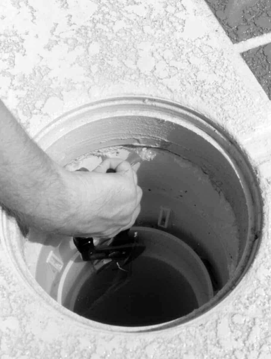
35 TROUBLE-SHOOTING How to "Open the Water Valve" WATER VALVE INSTRUCTIONS 1. TURN OFF THE PUMP. 2. To remove the Band Clamp, turn the "Tee Handle" counter-clockwise until it comes off the bolt. Note: You may have a 7/16" Nut instead of a Tee-Handle, if so use a wrench to remove it. 3. Lift the Top Dome off the Base. How to "Close the Water Valve" Check the "O-Ring" (or square gasket) and groove for debris, which could prevent a good seal. Remove any debris found and verify the O-Ring is in the groove properly. Place the Top Dome on the Base. You may face it any direction you like. Place the Band Clamp around the Valve Shells and put the Tee Handle or 7/16" Nut on the bolt. Tighten the Band Clamp securely. Note: Tapping the Band Clamp gently around the circle will help you tighten the Bolt with less effort. 4. Turn on the pump and inspect the Water Valve for any drips. If you find drips, turn off the pump and tighten the Band Clamp more. Note: Silicone "lubricant" makes O-Rings seal easier, but is rarely needed. NEVER USE PETROLEUM JELLY ON PLASTIC OR RUBBER. Module Installation (P/ N: ) 1. TURN OFF THE PUMP 2. "Open the Water Valve." 3. Lift the Module out of the Base. Note: The Module is designed to seal inside the Base so it may be difficult to lift. An easy solution is to turn the pump on and off quickly. CAUTION: make sure no one is standing nearby or he could get wet when the Module pops out of the Base. 4. Install the Module by aligning the pins on the bottom with the little holes in the Base. 5. Pool Trouble Shooting Guide 32
36 TROUBLE-SHOOTING POOL TROUBLE SHOOTING GUIDE ISSUE SOLUTION The System Doesn't Clean Like It Has Previously If the nozzles are turning on and off in groups, but don't clean as far as they once did, then the in-floor system isn't getting enough water to run effectively. A quick way to check this is by looking at the pressure gauge, it needs to be 20 PSI or above. Service the filtration system, clean all baskets, and clean the filter? Make sure auxiliary valves, spa jets, waterfalls, manual surface returns are not open when the pool is in it's cleaning mode. Dirt Collects Around One Nozzle. Nozzle stays up all the time When a Nozzle stays up, even when the pump is off, something is stuck in it. Try the following items one at a time until the problem is solved. Push the Nozzle down with a pool pole. Remove the Nozzle, rinse to remove all debris. Replace if damaged - Read Lifetime Limited Warranty. Nozzles are covered for life, if you are the original pool owner. Nozzle pops up and down, but does not rotate When the nozzle is up, try pushing on it with a pool pole. This may dislodge debris. Remove the Nozzle, rinse to remove all debris. Replace if damaged - Read Lifetime Limited Warranty. Nozzles have a lifetime guarantee, if you are the original pool owner. One Set of Nozzles Stay Up Whenever the Pump is On One set of Nozzles stays up all the time, even though the other sets cycle up and down. A part inside the Module has a problem. Debris is holding one piston open all the time. Remove the debris. Piston diaphragm is broken - Replace Module. 33
37 TROUBLE-SHOOTING ISSUE SOLUTION Clean Area Around One Zone Only When one set of Nozzles comes on with the pump each day, but never rotates more than once a day, the Water Valve isn't cycling. Pause Mode may be active. Turn the Knob on top of the Water Valve to RUN. Turbine may be jammed with debris. Open the Water Valve, remove the Module, and inspect Turbine. Look for debris. Does Turbine move freely? - If yes, the debris may be in the pipe out of sight. Turn on the pump for a few seconds to clear the line. Does turning Turbine turn the Gears? - If not replace Module. All Nozzles are floating when the pump is on When all Nozzles are floating, or have water running through them all at the same time check the Module. Module is missing - replace Module Module is damaged and all pistons are open. Replace module. Module is not seated properly - remove Module, remove any debris found inside Base and on Module, reinstall Module. Nozzle comes out of floor body Make sure O-Ring is in place and reinsert into floor body, turn clockwise 1/4 turn to seat If nozzle continues to come out, retainer lock is worn. Read lifetime limited warranty, nozzles are covered for life if you are the original pool owner. Replace nozzle. 34
38 NOTES 35
39 NOTES 36
40
AUTOMATIC IN-FLOOR CLEANING & CIRCULATING SYSTEM
 AUTOMATIC IN-FLOOR CLEANING & CIRCULATING SYSTEM INSTALLATION MANUAL U.S. Patent No.: 4,114,206, 4,939,797, 5,135,579, 5,251,343, 5,265,631 Notice to Installers: Read and follow these instructions. Give
MDX² INSTALLATION MANUAL
 ANTI-ENTRAPMENT DEBRIS DRAIN MDX² INSTALLATION MANUAL CONCRETE POOLS SUBMERGED SUCTION OUTLET FOR MULTIPLE DRAIN USE FOR USE ON FLOOR SEE SPECIAL INSTRUCTIONS FOR CALIFORNIA AND FLORIDA ON PAGES 4 AND
SAFETY VACUUM RELEASE SYSTEM (SVRS)
") SAFETY VACUUM RELEASE SYSTEM (SVRS) FOR EXISTING DEBRIS CANISTER APPLICATIONS INSTALLATION MANUAL MADE IN USA Safety compliant according to the Virginia Graeme Baker Pool and Spa Safety Act ASME A112.19.17-2010
SAFETY VACUUM RELEASE SYSTEM (SVRS) FOR EXISTING DEBRIS CANISTER APPLICATIONS INSTALLATION MANUAL MADE IN USA Safety compliant according to the Virginia Graeme Baker Pool and Spa Safety Act ASME A112.19.17-2010
Homeowners Manual. Thank you!
 Homeowners Manual Thank you! Thank you for purchasing a Blue Square Q360 In-Floor Cleaning System! With over 20 years of pool building and in-floor knowledge, this system was designed with you, our pool
U.S. Patent No.: 4,114,206, 4,939,797, 5,135,579, 5,251,343, 5,265,631
 AUTOMATIC INFLOOR CLEANING & CIRCULATING SYSTEM INSTALLATION MANUAL U.S. Patent No.: 4,4,206, 4,939,797, 5,35,579, 5,25,343, 5,265,63 Notice to Installers: Read and follow these instructions. Give these
COMMERCIAL STRENGTH POLYMER MEDIA FILTER OWNERS MANUAL
 COMMERCIAL STRENGTH POLYMER MEDIA FILTER OWNERS MANUAL INTRODUCTION Congratulations on choosing the Poolrite S6000 mk2, S5000 mk2, S8000 mk1 or S9000 mk4 High Rate Media Filter fitted with the exclusive
Owner's Manual. WS Series. Water Softener
 Owner's Manual WS-165-150 Series Water Softener Table of Contents WHAT'S INCLUDED 3 OPERATING CONDITIONS 4 ASSEMBLY INSTRUCTIONS 6 FLUSHING THE WATER LINES 13 MASTERPROGRAMMING 14 PROGRAMMING KEYAND GENERAL
541D19 SERIES. Technical Manual. A Division of Aquion Partners L.P.
 541D19 SERIES Technical Manual A Division of Aquion Partners L.P. Table of Contents Introduction... Page 1 Technical Specifications... Page 2 Flow Diagrams... Page 3 Injector & Flow Control Selection Injector...
Construction and Installation Instructions For the A&A Splash Pad
 Construction and Installation Instructions For the A&A Splash Pad Revised 9//09 These instructions are not meant to be detailed construction plans since you will be using your standard plumbing and deck
EXTREME 1 Reverse Osmosis System
 EXTREME 1 Reverse Osmosis System Leader Evaporator Co., Inc. 49 Jonergin Drive Swanton, VT 05488 Tel: 802-868-5444 www.leaderevaporator.com TABLE OF CONTENTS INTRODUCTION... 4 THEORY OF OPERATION... 4
Remote Water Quality System Standard Equipment (supplied by EPI) Remote Water Quality System Optional Equipment (supplied by EPI)
 Remote Water Quality System Optional Equipment (supplied by EPI)") Page 1 of 11 Parts List Remote Water Quality System Standard Equipment (supplied by EPI) 20sq ft Skimmer-Filter Remote Water Quality Plumbing Kit Heater-Controller Keypad Control 220V 3/4HP Circulation
Page 1 of 11 Parts List Remote Water Quality System Standard Equipment (supplied by EPI) 20sq ft Skimmer-Filter Remote Water Quality Plumbing Kit Heater-Controller Keypad Control 220V 3/4HP Circulation
Clean Water Made Easy. CWS Time Clock Softener Installation & Start Up Guide. Questions?
 Clean Water Made Easy www.cleanwaterstore.com CWS Time Clock Softener Installation & Start Up Guide Thank you for purchasing a Clean Water System! With proper installation and a little routine maintenance
Clean Water Made Easy
 Clean Water Made Easy http://www.cleanwaterstore.com Pro-OX 1650 Iron Filter Installation & Start-Up Guide Thank you for purchasing a Clean Water System! With proper installation and a little routine maintenance
INSTALLATION & OPERATING INSTRUCTIONS
 INSTALLATION & OPERATING INSTRUCTIONS WARNING RISK OF ELECTRIC SHOCK. CONNECT ONLY TO A CIRCUIT PROTECTED BY A GROUND-FAULT CIRCUIT-INTERRUPTER. THE UNIT SHOULD BE INSTALLED BY A QUALIFIED SERVICE REPRESENTATIVE.
SMF PUMP OWNER S MANUAL
 SMF PUMP OWNER S MANUAL IMPORTANT SAFETY INSTRUCTIONS READ AND FOLLOW ALL INSTRUCTIONS SAVE THESE INSTRUCTIONS WARNING: Before installing this product, read and follow all warning notices and instructions
Owner's Manual. (200 Gallon Lawn Service Skid Sprayer) Technical Specifications. Operation. General Information. Warranty/Parts/Service
 Technical Specifications. Operation. General Information. Warranty/Parts/Service") Owner's Manual (00 Gallon Lawn Service Skid Sprayer) Technical Specifications. Horsepower Recoil Start Engine Roller Cast Iron Pump 0 Gallons Per Minute at 0 PSI Pressure Gauge-Adjustable Pressure Range
Owner's Manual (00 Gallon Lawn Service Skid Sprayer) Technical Specifications. Horsepower Recoil Start Engine Roller Cast Iron Pump 0 Gallons Per Minute at 0 PSI Pressure Gauge-Adjustable Pressure Range
EXTREME HP-1 Reverse Osmosis System
 EXTREME HP-1 Reverse Osmosis System Leader Evaporator Co., Inc. 49 Jonergin Drive Swanton, VT 05488 Tel: 802-868-5444 www.leaderevaporator.com TABLE OF CONTENTS INTRODUCTION... 4 THEORY OF OPERATION...
IN-FLOOR TECH TRAINING 101
 REV 010917 IN-FLOOR TECH TRAINING 101 Paramount values the development of innovative products and strives to continue its mission of making pool life simplified. The same passion for great products is
IMPORTANT SAFETY INSTRUCTIONS READ AND FOLLOW ALL INSTRUCTIONS SAVE THESE INSTRUCTIONS. Table of Contents WARNING.
 Eagle Pump Owners Manual IMPORTANT SAFETY INSTRUCTIONS READ AND FOLLOW ALL INSTRUCTIONS SAVE THESE INSTRUCTIONS Table of Contents SECTION I. INSTALLATION... 2 SECTION II. OPERATION & MAINTENANCE... 2 SECTION
Clean & Clear. Cartridge Filter System Owner s Manual IMPORTANT SAFETY INSTRUCTIONS READ AND FOLLOW ALL INSTRUCTIONS SAVE THESE INSTRUCTIONS
 Clean & Clear Cartridge Filter System Owner s Manual IMPORTANT SAFETY INSTRUCTIONS READ AND FOLLOW ALL INSTRUCTIONS SAVE THESE INSTRUCTIONS SECTION I. SECTION II. SECTION III. SECTION IV. SECTION V. SECTION
Clean Water Made Easy
 Clean Water Made Easy http://www.cleanwaterstore.com Pro-OX 2510 Iron Filter Installation & Start- Up Guide Thank you for purchasing a Clean Water System! With proper installation and a little routine
Assembly- and Usermanual. Rainmaker. Code No GB. Edition: 09/2007
 Assembly- and Usermanual Rainmaker Code No. 99-97-1729 GB Edition: 09/2007 Table of contents Page I 1 Overview and system specifications.................................. 1 1.1 Purpose of Evaporative
CHAMPION PUMP OWNER S MANUAL
 CHAMPION PUMP OWNER S MANUAL IMPORTANT SAFETY INSTRUCTIONS READ AND FOLLOW ALL INSTRUCTIONS SAVE THESE INSTRUCTIONS WARNING: Before installing this product, read and follow all warning notices and instructions
Safety. Rinse Kit for Multi-Pro 1200 and 1250 Turf Sprayers Model No Safety and Instructional Decals. Installation Instructions
 Rinse Kit for Multi-Pro 1200 and 1250 Turf Sprayers Model No. 106-4842 Form No. 3353-529 Rev B Installation Instructions Note: Determine the left and right sides of the machine from the normal operating
ECONO FLO VSA 165 VARIABLE SPEED PUMP OWNER S MANUAL
 ECONO FLO VSA 165 VARIABLE SPEED PUMP OWNER S MANUAL IMPORTANT SAFETY INSTRUCTIONS READ AND FOLLOW ALL INSTRUCTIONS SAVE THESE INSTRUCTIONS WARNING: Before installing this product, read and follow all
Model K 3000 G Part No
 K3000G Manual 11/30/01 4:56 PM Page 1 Model K 3000 G Part No. 1.133-110.0 High Pressure Washer Operator Manual Overview..................................1 Precautions...............................1-2
AQUAS POOL PACKAGE INSTALLATION INSTRUCTIONS FOR MODELS: XPN AQUAS Pool Package
 AQUAS POOL PACKAGE INSTALLATION INSTRUCTIONS FOR MODELS: XPN 400 801 AQUAS Pool Package The AQUAS pool package system is a high efficiency commercial condensing boiler, pre-piped package system from the
INSTALLATION INSTRUCTIONS GEO PRIME TANK. (Patent Pending) GPC
 GPC") INSTALLATION INSTRUCTIONS GEO PRIME TANK (Patent Pending) GPC Table of Contents General Description 2 Installation 3 Flushing and Purging 5 Initial Start up 7 Adding or Checking Fluid 8 Replacing a Pump
INSTALLATION INSTRUCTIONS GEO PRIME TANK (Patent Pending) GPC Table of Contents General Description 2 Installation 3 Flushing and Purging 5 Initial Start up 7 Adding or Checking Fluid 8 Replacing a Pump
EXTREME 2 Reverse Osmosis System
 EXTREME 2 Reverse Osmosis System Leader Evaporator Co., Inc. 49 Jonergin Drive Swanton, VT 05488 Tel: 802-868-5444 www.leaderevaporator.com TABLE OF CONTENTS INTRODUCTION... 4 THEORY OF OPERATION... 4
ECONO FLO 2.7HP VARIABLE SPEED PUMP OWNER S MANUAL
 ECONO FLO 2.7HP VARIABLE SPEED PUMP OWNER S MANUAL IMPORTANT SAFETY INSTRUCTIONS READ AND FOLLOW ALL INSTRUCTIONS SAVE THESE INSTRUCTIONS WARNING: Before installing this product, read and follow all warning
Aer-Max Installation Instructions
 Aer-Max Installation Instructions Congratulations on selecting this quality Aer-Max system. Important: Please read all instructions before assembling and installing the Aer-Max system. Consult local plumbing
Installation Instructions for. OmniFount
 Installation Instructions for OmniFount Congratulations, you have just purchased the finest watering fountain on the market. This unit is built to give you excellent service when properly installed and
Fleck 2510 Sediment Filter Installation & Start-Up Guide
 Clean Water Made Easy www.cleanwaterstore.com Fleck 2510 Sediment Filter Installation & Start-Up Guide Thank you for purchasing a Clean Water System! With proper installation and a little routine maintenance
7800 Neutralizer Installation & Start-Up Guide
 Clean Water Made Easy www.cleanwaterstore.com 7800 Neutralizer Installation & Start-Up Guide Thank you for purchasing a Clean Water System! With proper installation and a little routine maintenance your
INSTRUCTIONS FOR USE PORTABLE VACUUM SYSTEM LEI Part # s / , , , IMPORTANT INFORMATION
 INSTRUCTIONS FOR USE PORTABLE VACUUM SYSTEM LEI Part # s / 27-009, 27-010, 27-015, 27-020 IMPORTANT INFORMATION UNATHORIZED CHANGES OR ALTERATIONS TO ANY LINCOLN PORTABLE VACUUM SYSTEM WILL AUTOMATICALLY
5700-E Sediment Filter Installation & Start-Up Guide
 Clean Water Made Easy www.cleanwaterstore.com 5700-E Sediment Filter Installation & Start-Up Guide Thank you for purchasing a Clean Water System! With proper installation and a little routine maintenance
Hydrotherapy Jets (Remote Water Quality System)
") Page 1 of 6 Parts List (_) - 50 Roll of Flex PVC pipe 1-3/4 HP Circulating Centrifugal Pump 1 25 Roll of Flex PVC pipe 4-1 1 / 2 " Tees 2-1 1 / 2 " Ball Valves 2 - Female slip couplers 4-1/2" 90 degree
Page 1 of 6 Parts List (_) - 50 Roll of Flex PVC pipe 1-3/4 HP Circulating Centrifugal Pump 1 25 Roll of Flex PVC pipe 4-1 1 / 2 " Tees 2-1 1 / 2 " Ball Valves 2 - Female slip couplers 4-1/2" 90 degree
Parts & Material Included
 O² Hydro Well System Installation, Use & Care Guide Parts & Material Included 1. Funnel 11. Drain Line 21. Air Head 2. Media Tank Distributer Tube 12. Air Release 22. Drain Fitting 3. Air Tank Distributer
1 Introduction Basic Heliocol terminology Designing your system Parts and tools Hydraulics Installation...
 INSTALLATION MANUAL SWIMMING POOL SOLAR HEATING SYSTEM Before attempting installation, read these instructions and acquaint yourself with the component names. Great care has been taken to make this an
SYSTEMS for CATALYTIC FILTERS
 OP40U5F, OP40B5F, OP80U10F, OP80B10F, OP120U15F & OP120B15F INSTALLATION, OPERATION & SERVICE INSTRUCTIONS Hydrogen Sulfide Removal SYSTEMS for CATALYTIC FILTERS NO DIAPHRAGMS OR AIR CELLS COMPLETELY CORROSION
Clean Water Made Easy
 Clean Water Made Easy http://www.cleanwaterstore.com Pro-OX 5700-E Iron Filter Installation & Start-Up Guide Thank you for purchasing a Clean Water System! With proper installation and a little routine
HARMSCO INSTALLATION AND OPERATION MANUAL UPFLOW SWIMMING POOL CARTRIDGE FILTER CARTRIDGE CLEANING INSTRUCTIONS HARMSCO CARTRIDGES
 HARMSCO INSTALLATION AND OPERATION MANUAL UPFLOW SWIMMING POOL CARTRIDGE FILTER CARTRIDGE CLEANING INSTRUCTIONS HARMSCO CARTRIDGES May be cleaned and reused before replacement is necessary. Cartridge cleaning
TIDALWAVE I/G POOL PUMP INSTRUCTION MANUAL
 TIDALWAVE I/G POOL PUMP INSTRUCTION MANUAL READ THIS MANUAL CAREFULLY BEFORE USING YOUR PUMP 88 PUMP PARTS BREAKDOWN REF # Order # Mfr # Description 1 NEP4 AC 348 Lid Knobs NEP AC 380 Strainer Lid 3 NEP6
EXTREME HC-2 Reverse Osmosis System
 EXTREME HC-2 Reverse Osmosis System Leader Evaporator Co., Inc. 49 Jonergin Drive Swanton, VT 05488 Tel: 802-868-5444 www.leaderevaporator.com Contents INTRODUCTION... 3 THEORY OF OPERATION... 4 Terms...
EXTREME HC-8 Reverse Osmosis System
 EXTREME HC-8 Reverse Osmosis System Leader Evaporator Co., Inc. 49 Jonergin Drive Swanton, VT 05488 Tel: 802-868-5444 www.leaderevaporator.com TABLE OF CONTENTS INTRODUCTION... 4 THEORY OF OPERATION...
Water Softener Installation Guide Effective for all Softeners from our Range
 Water Softener Installation Guide Effective for all Softeners from our Range Planning Your Installation Always observe the water byelaws. Ensure there is only one rising main, that you have allowed space
Model LF-310 Air Operated
 Microflush Half Gallon Toilets Model LF-310 Air Operated Installation/Service Manual P/N 24156 452 East Hill Road Fax: 707.459.6617 Willits, CA 95490 USA E-mail: info@microphor.com Phone: 707.459.5563
INSTALLATION AND OPERATION MANUAL
 F OR I NGROUND P OOLS INSTALLATION AND OPERATION MANUAL How Solar Pool Heating Works Why SunHeater TM Works Best Using your pool pump, water is automatically pumped through the solar collectors. The water
Media Service Instructions 1500 Series BAT Media Plants
 R Media Service Instructions 1500 Series BAT Media Plants J-500 MEDIA SERVICE Read these instructions and perform every step. After servicing 2 or 3 installations, you will only have to refer to these
STOP. SAFETY INFORMATION Please read and understand this entire manual before attempting to assemble, operate or install the product.
 STOP Power supply required Questions, problems, missing parts? Before returning to your retailer, call our customer service department at 1-800-742-5044, 7:30 a.m. - 5 p.m., EST, Monday - Friday. 115 volts
Installation. Please keep this manual for future reference.
 Installation Tecma Bathroom Anywhere Owner s and Installation Manual Please keep this manual for future reference. Read ALL these instructions before installing the Tecma Bathroom Anywhere unit. Warning
INSTALLATION INSTRUCTIONS WARRANTY
 QT FLOW CENTER INSTALLATION INSTRUCTIONS Fig. 1. Low Head Pump Center Flow Chart Fig. 2. High Head Pump Center Flow Chart NOTE: Read the entire instruction manual before starting the installation. WARRANTY
Closing procedures for in-ground pools
 Closing procedures for in-ground pools Note: Carefully read this entire document before closing your pool. The following procedures are also available in video format under the «Videos» tab at www.trevi.com.
Installation Manual PS-225 & PS-275
 Installation Manual PS-225 & PS-275 Table of Contents Pre-Uncrating Checklist... 1 Verifying System Requirements... 2 Verifying System Direction... 2 Verifying the Electrical Requirements... 2 Removal
Fleck 5600 Carbon Filter Installation & Start Up Guide
 Clean Water Made Easy www.cleanwaterstore.com Fleck 5600 Carbon Filter Installation & Start Up Guide Thank you for purchasing a Clean Water System! With proper installation and a little routine maintenance
OWNERS GUIDE TO INSTALLATION AND OPERATION
 OWNERS GUIDE TO INSTALLATION AND OPERATION SPM SERIES HIGH POWER CENTRIFUGALS READ THESE INSTRUCTIONS CAREFULLY Read these installation instructions in detail before installing your pump. Be sure to check
Elite Primer Baldor Series External Pond Pump
 Elite Primer Baldor Series External Pond Pump ( 5250PPB21, 6440PPB23, 7550PPB26, 9600PPB28) Installation and User s Guide IMPORTANT SAFETY INSTRUCTIONS, READ AND FOLLOW ALL INSTRUCTIONS. SAVE THESE INSTRUCTIONS
PolyMax H2-24 Dutch Bucket System
 11234 PolyMax H2-24 Dutch Bucket System *Actual system may differ. PolyMax Dutch Buckets Versatile PolyMax Dutch Buckets are ideal for both small- and large-scale hydroponic growing. 2017 FarmTek All Rights
FOR PRODUCT/WARRANTY REGISTRATION Go to Click on SUPPORT at the top of homepage Click on PRODUCT REGISTRATION
 Salvajor Commercial Disposers For All Models: 75, 00, 50, 200, 300, 500, 750 Models 75-200 Models 300-750 2 Typical Installations & Installation of Cone Bowl or Sink Collar 3 Attaching Disposer to Cone
EDGEMERE DUAL CONTROL WIDESPREAD LAVATORY FAUCET INSTALLATION INSTRUCTIONS
 EDGEMERE DUAL CONTROL WIDESPREAD LAVATORY FAUCET INSTALLATION INSTRUCTIONS 0.0 Thank you for selecting American Standard... the benchmark of fine quality for over 00 years. To ensure that your installation
AQUAS POOL PACKAGE INSTALLATION INSTRUCTIONS FOR MODELS: AP AQUAS Pool Package
 100285340_2000542910_Rev A AQUAS POOL PACKAGE INSTALLATION INSTRUCTIONS FOR MODELS: AP 400-850 AQUAS Pool Package The AQUAS pool package system is a high efficiency commercial condensing boiler, pre-piped
Installation Manual PS-200 & PS-201
 Installation Manual PS-200 & PS-201 Table of Contents Pre-Uncrating Checklist... 1 Verifying System Requirements... 2 Verifying System Direction... 2 Verifying the Electrical Requirements... 2 Removal
Model K 4400 G Part No High Pressure Washer
 Model K 4400 G Part No. 1.133-208.0 High Pressure Washer Table of Contents Overview..................................1 Precautions...............................1-2 Assembly Instructions.........................3
2 SPEED PUMP INSTRUCTION MANUAL READ THIS MANUAL CAREFULLY BEFORE USING YOUR 2 SPEED PUMP
 2 SPEED PUMP INSTRUCTION MANUAL READ THIS MANUAL CAREFULLY BEFORE USING YOUR 2 SPEED PUMP 8308 PUMP PARTS BREAKDOWN Ref # Part # Manf. # Descrip on 1 NEP2134 AC 81361 PUMP LID 2 NEP2135 AC 81396 PUMP LID
POOL WINTERIZING INSTRUCTIONS
 TASK CHECKLIST 1. Clean the Filter 2. Remove the Deck Equipment 3. Clean the Pool 4. Lower the Water Level 5. Apply Chemicals 6. Freeze Proof Equipment & Plumbing Lines 7. Put on the Winter Cover Note:
ETL listed for installations within 5 ft. (1.5M) of outer edge of water
 of outer edge of water") Light Streams Lighted Bubbler Kit Gunite 2LSLBK (75 strands of Fiber per Bubbler) SAVE THESE INSTRUCTIONS! Fiberstars Light Streams Lighted Bubbler is a very simple device to provide lighted water for
Light Streams Lighted Bubbler Kit Gunite 2LSLBK (75 strands of Fiber per Bubbler) SAVE THESE INSTRUCTIONS! Fiberstars Light Streams Lighted Bubbler is a very simple device to provide lighted water for
TECHNICAL DATA. Wet 26a. February 22, 2009
 February 22, 2009 Wet 26a 1. DESCRIPTION The Viking Alarm Check Valve serves as a check valve by trapping pressurized water above the clapper and preventing reverse flow from sprinkler piping. The valve
COBRA -H EXTRACTOR 120V
 COBRA -H EXTRACTOR 120V INFORMATION & OPERATING INSTRUCTIONS CAUTION: DO NOT OPERATE MACHINE UNTIL YOU HAVE READ ALL SECTIONS OF THIS INSTRUCTION MANUAL IMPROPER USE OF THE MACHINE WILL VOID THE WARRANTY
INSTALLATION INSTRUCTIONS
 INSTALLATION INSTRUCTIONS MODEL: BISTRO THERMO SHOWER KIT (RH-5344) 1 Restoration Hardware Thermo Shower Kit Specification Diagram 2 All Threaded Connections are 3/4 NPT Dimensions are in Inches and Approximation
Closing procedures for in-ground pools
 Closing procedures for in-ground pools Note: Carefully read this entire document before proceeding with the closure of your pool. In order to avoid unpleasant surprises, please check with your insurance
OWNER S MANUAL AND INSTALLATION GUIDE PLEASE READ THIS MANUAL CAREFULLY BEFORE ATTEMPTING INSTALLATION
 ClearChoice Economy Under Sink Drinking Water System OWNER S MANUAL AND INSTALLATION GUIDE PLEASE READ THIS MANUAL CAREFULLY BEFORE ATTEMPTING INSTALLATION Congratulations on the purchase of your ClearChoice
EXTREME 4 Reverse Osmosis System
 EXTREME 4 Reverse Osmosis System Leader Evaporator Co., Inc. 49 Jonergin Drive Swanton, VT 05488 Tel: 802-868-5444 www.leaderevaporator.com TABLE OF CONTENTS INTRODUCTION... 4 THEORY OF OPERATION... 4
Installation Instructions for. OmniFount
 Installation Instructions for OmniFount Congratulations, you have just purchased the finest watering fountain on the market. This unit is built to give you excellent service when properly installed and
INSTALLATION & INSTRUCTION MANUAL
 INSTALLATION & INSTRUCTION MANUAL CLEARADON SERIES 3311 SHALLOWTRAY AERATION SYSTEM RadonAway 3 Saber Way Ward Hill, MA 01835 radonaway.com TABLE OF CONTENTS SAFETY FIRST!... 1 INSTALLATION PROCEDURE...
Model T Professional Series 3/4HP 2 YEAR WARRANTY SEWAGE PUMP
 Model T00405 REPAIR PARTS REF. PART DESCRIPTION REF. PART DESCRIPTION 1 450331 Strainer 2 450332 Oil cover "O" ring 3 400447 Impeller 4 450333 Pump casing 5 400450 Oil cover 6 400449 Oil seal 7 400448
Pool Power Pak. III with On/Off Switch UL Models (1 HP), (1-1/2 HP) NEC Models (1 HP), (1-1/2 HP)
, (1-1/2 HP) NEC Models (1 HP), (1-1/2 HP)") the original portable pool Pool Power Pak III with On/Off Switch UL Models 0-1076-000 (1 HP), 0-1077-000 (1-1/2 HP) NEC Models 0-1076-006 (1 HP), 0-1077-006 (1-1/2 HP) Owner's Guide 365-1783 PREPARATION
the original portable pool Pool Power Pak III with On/Off Switch UL Models 0-1076-000 (1 HP), 0-1077-000 (1-1/2 HP) NEC Models 0-1076-006 (1 HP), 0-1077-006 (1-1/2 HP) Owner's Guide 365-1783 PREPARATION
Series 47 and 247 Mechanical Water Feeders. Series 47-2 and Combination Mechanical Water Feeder/Low Water Cut-Off ! WARNING
 Series 47 and 247 Mechanical Water Feeders McDonnell & Miller Installation & Maintenance Instructions MM-316(C) Series 47-2 and 247-2 Combination Mechanical Water Feeder/Low Water Cut-Off Series 47 Water
ACROBAT GT OPERATING AND TROUBLESHOOTING GUIDE. Automatic Pool Cleaner. We hope you enjoy your ACROBAT GT automatic pool cleaner!
 ACROBAT GT Automatic Pool Cleaner OPERATING AND TROUBLESHOOTING GUIDE 36 fin disc and flexible foot constructed of quality polyurethane Proven technology: Diaphragm driven strength & quietness Unique hose
SOLUS-500 EXTRACTOR 120V
 SOLUS-500 EXTRACTOR 120V INFORMATION & OPERATING INSTRUCTIONS DO NOT OPERATE MACHINE UNTIL YOU HAVE READ ALL SECTIONS OF THIS INSTRUCTIONS IMPROPER USE OF THE MACHINE WILL VOID THE WARRANTY 1. Always use
MODEL E
 www.burcam.com 2190 Dagenais Blvd. West TEL: 514.337.4415 LAVAL (QUEBEC) FAX: 514.337.4029 CANADA H7L 5X9 info@burcam.com Your pump has been carefully packaged at the factory to prevent damage during shipping.
INSTALLATION INSTRUCTIONS
 INSTALLATION INSTRUCTIONS 67000 6700 MODEL: SPRITZ 67000 (RH-600) 6700 (RH-600X) REV.C Restoration Hardware Faucet Product Size Specification Diagram Recommended Deck Hole Size -/8 Diameter Dimensions
Safety Vacuum Release System Installation Instructions. Model VA
 Safety Vacuum Release System Installation Instructions Model VA-2000 Vac-Alert TM Industries, LLC 4505 775 8th Prosperity Court, Suite Drive 4 Fort Vero Pierce, Beach, FL 32962 34981 www.vac-alert.com
REVE ORDERING INFORMATION NOTES T01-A INSTALLATION INSTRUCTIONS 现代型分体座便器 CONTEMPORARY TWO-PIECE TOILET K-17178T-S/K-17178T-SP
 REVE INSTALLATION INSTRUCTIONS 现代型分体座便器 CONTEMPORARY TWO-PIECE TOILET K-17178T-S/K-17178T-SP Please read these instructions carefully to familiarize yourself with the required tools, materials, and installation
INSTALLATION INSTRUCTIONS CARE AND MAINTENANCE
 INSTALLATION INSTRUCTIONS CARE AND MAINTENANCE Heritage VorMax Right Height Elongated 2-piece Toilet Model 205AA104 Thank you for selecting American Standard - the benchmark of fine quality for over 100
1 ESMA, Inc. P. O. BOX 734 * SOUTH HOLLAND, IL * (800) * FAX (708)
 * FAX (708)") 1 2 Instructions for Ultrasonic Washer E789 (U.L. Approved) 1. INTRODUCTION The E789 Automatic Ultrasonic Washer automatically performs a cleaning cycle, the major steps of which are: Ultrasonic cleaning
1 2 Instructions for Ultrasonic Washer E789 (U.L. Approved) 1. INTRODUCTION The E789 Automatic Ultrasonic Washer automatically performs a cleaning cycle, the major steps of which are: Ultrasonic cleaning
MAXI PUMP INSTRUCTION MANUAL NE6151B /NE6171B READ THIS MANUAL CAREFULLY BEFORE USING YOUR MAXI PUMP
 MAXI PUMP INSTRUCTION MANUAL NE6151B /NE6171B READ THIS MANUAL CAREFULLY BEFORE USING YOUR MAXI PUMP 8104 MAXI-PUMP PARTS BREAKDOWN Re f # 1 2 3 4 5 6 7a 7b 8 9 10 11 12 13 14 15 16 2 Part # NEP2134 NEP2135
Isolux Arsenic Removal Systems Central Treatment Systems Operation and Maintenance Manual
 500 Point Breeze Rd. Flemington, NJ 08822 (908) 782-5800 Phone (908) 782-3380 FAX www.zrpure.com Isolux Arsenic Removal Systems Central Treatment Systems Operation and Maintenance Manual - 1 Contents 1.
Instruction Manual - Anti-Siphon Ejector Chlorine & Sulfur Dioxide 500 PPD (10 kg/h) Maximum Capacity
 Maximum Capacity") - Anti-Siphon Ejector Chlorine & Sulfur Dioxide 500 PPD (10 kg/h) Maximum Capacity 100 PPD (2 kg/h) Chlorine or Sulfur Dioxide 250 & 500 PPD (5 & 10 kg/h) Chlorine or Sulfur Dioxide Anti-Siphon Ejector
- Anti-Siphon Ejector Chlorine & Sulfur Dioxide 500 PPD (10 kg/h) Maximum Capacity 100 PPD (2 kg/h) Chlorine or Sulfur Dioxide 250 & 500 PPD (5 & 10 kg/h) Chlorine or Sulfur Dioxide Anti-Siphon Ejector
INSTALLATION INSTRUCTIONS
 ,t_2007 Lennox Industries Inc. Dallas, Texas, USA INSTALLATION INSTRUCTIONS CH33 Series Units EVAPORATOR 505,264M (65484504) 10/07 Supersedes 09/06 COILS n _putech blications ical Litho U.S.A. RETAIN THESE
Troubleshooting the MPH 24FP Series Pedestal Hydrant
 MAPA Products P.O. Box 129 Naples, Texas 75568 Toll Free: 877 897 2371 How the Hydrant Works: Troubleshooting the MPH 24FP Series Pedestal Hydrant The design of the hydrant assembly is based on a venturi
QUIETFLO OWNER S MANUAL
 QUIETFLO OWNER S MANUAL INSTALLATION, OPERATION & PARTS To prevent potential injury and to avoid unnecessary service calls, read this manual carefully and completley. CAUTION - We highly recommend a qualified
INSTALLATION INSTRUCTIONS
 INSTALLATION INSTRUCTIONS Percy Single Control Lavatory and Vessel Faucet Loop Handle Lavatory - Model D00 Pixie Handle Lavatory - Model D000 Loop Handle Vessel - Model D0 Pixie Handle Vessel - Model D00
Jacuzzi J-D300 Pool Cleaning System
 Jacuzzi J-D300 Pool Cleaning System Limited Warranty Terms & Conditions 1 year warranty coverage, exclusions apply J-D300 Before using the cleaner, review the owner s manual completely. Failure to read
PIPE DREAMS 96. Aeroponic Garden IMPORTANT:
 1 WARNING: BEFORE PUTTING WATER PUMP INTO OPERATION FILL UP NUTRIENT TANK TO TOP OF PUMP. THE PUMP MUST NEVER RUN DRY OTHERWISE, WARRANTY WILL BE DECLINED. READ FILLING INSTRUCTIONS BEFORE USE. Welcome
568X, 587X, 588X Series
 Please read and save this Repair Parts Manual. Read this manual and the General Operating Instructions carefully before attempting to assemble, install, operate or maintain the product described. Protect
model NO. LSS GALLON SKID MOUNTED HIGH PRESSURE SPRAYER ASSEMBLY / OPERATION INSTRUCTIONS / PARTS
 000 model NO. LSS- 00 GALLON SKID MOUNTED HIGH PRESSURE SPRAYER ASSEMBLY / OPERATION INSTRUCTIONS / PARTS Part number and descriptions can be obtained from the illustrated parts list section of this manual.
ONE PIECE TOILET LT3. Model: MPN: B0940 INSTALLATION INSTRUCTIONS. Version: 1.0
 Model: MPN: B0940 INSTALLATION INSTRUCTIONS Version: 1.0 READ ALL INSTRUCTIONS BEFORE UNPACKING THE PRODUCT INSTRUCTIONS THAT, IF IGNORED COULD RESULT IN DEATH OR SERIOUS INJURY CAUSED BY INCORRECT HANDLING
INSTALLATION, OPERATION AND SERVICE MANUAL AERATION SYSTEMS FEATURING AIR COMPRESSOR AND AIR ELIMINATOR TANK
 INSTALLATION, OPERATION AND SERVICE MANUAL AERATION SYSTEMS FEATURING AIR COMPRESSOR AND AIR ELIMINATOR TANK FOR USE WITH 1 CU. FT. AUTOMATIC BACKWASHING FILTERS 7-LAER1047-115 AERATION SYSTEM 7-LAER1047-230
DOUBLE O-RING GEO-PRIME TANK Non-Pressurized Flow Center System INSTALLATION INSTRUCTIONS. Model: DORGPT-1 NOTE:
 INSTALLATION INSTRUCTIONS DOUBLE O-RING GEO-PRIME TANK Non-Pressurized Flow Center System Model: DORGPT-1 NOTE: This guide provides the installer with instructions specific to the Bard Double O-Ring Geo-Prime
A AD Oil burners fuel unit. deltapumps.com. DE A-AD_en_0709.pdf Page 1/1
 A AD Oil burners fuel unit deltapumps.com DE116-0709 A-AD_en_0709.pdf - 16.11.09 Page 1/1 Oil burners fuel unit Type A, AD 1- Applications The DELTA aluminium fuel unit type A is an efficient and modern