ClimateWell package solution description
|
|
|
- Iris Annabelle McDaniel
- 5 years ago
- Views:
Transcription

1 ClimateWell package solution description Edited by: Olof Hallström Version 3.0 Institution Stockholm, January 21, 2010
2 Table of Contents ClimateWell package solution description Introduction The Chiller System s Components Solar Collectors Collector Fluid Stagnation Behaviour Pipes Losses Distribution System Air Handling Unit ClimaDeck Chilled Beam System Heat Rejection Swimming Pool Wet Cooling Tower Preheating of DHW Storage Thermal Storage Page 2 of 28
3 3.5 DHW Preparation Hydraulic Design Solar Pump Station Expansion Vessel Cooling Vessel Deairation Strainer Safety Valves Heat Exchangers Pumps System Schematic Proposed Package Solution Summary Page 3 of 28

4 1 Introduction ClimateWell s Solar Cooling product combines the best features of absorption and adsorption with its patented triple state absorption technology. Among many features low electricity consumption, no noise, no crystallization problems and the integrated storage capacity are some of the most important ones. ClimateWell has offices in both Stockholm and Madrid and a manufacturing plant in Olvega, Spain. Within the Solarcombi+ project standard package solutions have been developed that will minimize the pre-engineering efforts for each project and hence lower the overall system costs. Page 4 of 28


5 2 The Chiller The machine consists of three parts: two twin barrels that work independently and one plumbing unit that connects the two barrels to the external circuits. The machine is connected to three external circuits: the thermal energy supply, the heat sink and the cooling/heating distribution. The thermal energy supply is the circuit where the solar panels, the burner or other energy source powers the ClimateWell Solar Chiller. The heat sink dissipates all the energy that is collected from the house and all the energy that is collected from the solar panels. As for the heat sink, it is possible to use a pool, a geothermal borehole or a cooling tower. The cooling/heating supply distributes the cooling and heating in the house. There are several ways to distribute the cooling and heating. The two barrels work in two different phases: charging and discharging. When a barrel is charging, it is connected to the heat sink and to the thermal energy supply. When a barrel is discharging, it is connected to the heat sink and to the cooling/heating distribution. In standard operation the machine works in what is called normal mode, which means that one barrel is charging while the other is discharging. Consequently the machine is always able to both supply cooling and charge with the thermal energy supplied. Charge Discharge Page 5 of 28
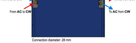
6 Operational Data ClimateWell Solar Chiller Heat Source Circuit Flow l/min Typical Power Range kw Operational Temperature Out 75 C 100 C In 85 C 110 C Operational Pressure 3 bars Maximum Pressures 6 bars Type of Fluid Propylene Glycol 1,2 L 15 % concentration Distribution Circuit Flow l/min Nominal Power Operational Temperature Type of Fluid See Power Curves Out 10 C 16 C In 15 C 21 C Propylene Glycol 1,2 L 15 % concentration Heat Rejection Circuit Flow l/min Operational Temperature Out 30 C to 45 C In < 30 C Technical Data Type of Fluid Average Power Consumption Electrical 18 W Propylene Glycol 1,2 L 15 % concentration ClimateWell Solar Chiller COP (Thermal) Triple state absorption process COP Implemented COP will depend on installation characteristics, typically 0,52-0,57. The Maximum Temperature to ClimateWell From Heat Source 120 C Maximum Pressure From Heat Source 10 bar Heat Source Circuit 30 kpa at 25l/min Pressure Drop Heat Rejection Circuit 38 kpa at 50l/min Distribution Circuit 45 kpa at 25l/min Energy Storage Capacity Cooling 56 kwh Weight 990 kg Fluid Volume Operational 74,5 l Salt Solution Lithium chloride LiCl Page 6 of 28
7 ClimateWell Solar Chiller Electrical connections ClimateWell Solar Chiller Vac 230 Communication Protocol RS , 8,None, 1 Output Signals AC pump On/off (5V/0V 20 ma) Input signals SP pump HS pump Output mode status Output mode AC pump status On/off (5V/0V 20 ma) On/off (5V/0V 20 ma) Cooling/Heating (5V/0V 20 ma) Normally open Toggle between heating and cooling when closed On/off (5V/0V 20 ma) Page 7 of 28


8 ClimateWell Solar Chiller Page 8 of 28
9 3 System s Components 3.1 Solar Collectors Use only certified highly efficient solar collectors with selective absorber plates. Both flat plate and evacuated tube collectors can be used although evacuated tubes generally offer higher efficiencies for high temperature ranges. Since low pressure drop, delta temperature between inlet and outlet, and emptying behaviour during stagnation are very important parameters in solar cooling installations, flat plate collectors with double harp hydraulics are not recommended. For evacuated tube collectors both direct flow and heat pipe solutions can be used. The number of collector panels in each bank of the array should be according to the panel manufacturer s guidelines. Design the individual collector banks so that the temperature difference between inlet and outlet at maximum irradiation is no more than 20 C for the nominal flow. Install reversed return hydraulics to ensure the same pressure drop in each bank in the collector array regardless of the flow. This is a requisite for using variable flow in the collector loop. Install temperature sensors in each collector bank inlet and outlet. These sensors are used to make sure that the same flow is passing each collector bank in the array. Manual bypass flow meters can also be used in each bank. Use an immersed solar collector temperature sensor on any bank in the collector array, and a second sensor close to ClimateWell unit outlet for pump control. Make sure that the sensor is measuring the collector temperature and not the flow temperature in the pipes. A temperature sensor attached to the pipe cannot be used for pump control since the sensor must be able to measure the absorber plate temperature even when the solar pump is off. The specific collector flow rate (the flow rate through one collector) should be according to manufacturer specifications and the hydraulic configuration should be designed to match the flow demanded by the Climatewell units. Generally the total solar field flow is in the range of 20 to 50 l/hr per m2 aperture area depending on the type of solar collector. Figure 1 Figure 3 illustrates some examples on possible hydraulic configurations for different solar collectors. Page 9 of 28


10 Figure 1: Double meandering hydraulics with two parallel banks with each eight collectors also connected in parallel. Both direct flow and heat pipe evacuated tubes can be connected in a similar way, with the difference that the collectors in each bank is internally connected in series instead of in parallel. Figure 2: Double meandering hydraulics with four parallel banks with each four collectors also connected in parallel. Both direct flow and heat pipe evacuated tubes can be connected in a similar way, with the difference that the collectors in each bank is internally connected in series instead of in parallel. Page 10 of 28

11 Figure 3: Simple harp hydraulics with four banks connected in series with each four collectors connected in parallel. Simple harp is a high flow solar collector and it is recommended to have at least four collectors in series in order to obtain sufficient flow through each collector. More than four collectors in parallel in one bank are not recommended because the flow is then unevenly distributed Collector Fluid Use only reversibly evaporisable heat transfer fluid based on propylene glycol and non-toxic corrosion inhibitors with ph buffering capacity for utilization in solar heating installations. The fluid should be able to withstand at least 170 C without being altered Stagnation Behaviour Use a safety algorithm for the solar pump that automatically shuts off the solar pump if the collector temperature exceeds 130 C. The solar pump must under no circumstances be turned on during collector stagnation. Install pipe work for both flow and return with a continuous upward slope towards the solar field. This will give a slower and more controlled vapour transport during stagnation. Make sure that the vapour always has somewhere to expand. There must be an unhindered path from the solar collectors to the expansion vessel in order to avoid pressure peaks Pipes Design pipe dimensions to have m/s flow velocity, but never more than 10 mm/m (mm pressure head per length meter pipe) pressure drop. Page 11 of 28
12 Use only copper or stainless steel pipe material in any high temperature circuit. Stainless steel offers the most efficient and reliable performance for the collector loop. Always follow or exceed local or regional normative when designing the pipe work. Higher flow velocities than 1.5 m/s will give unnecessarily high pressure drop in the loop, and lower velocities than 0.5 m/s will make it impossible for air bubbles to reach the purge unit while increasing the thermal losses. In order to avoid confusion when connecting the pipes the flow and return can have different colours, see Figure Losses Insulation should be of a sufficient thickness and standard in order to limit heat loss from the pipes to and from the collector field. Less than 0.15 W/K per length meter pipe is recommended. The insulation must be resistant to weathering and meet or exceed the requirements of standards such as EN 483 or EN 513. Collector inclination, orientation and shading affect the performance of the solar cooling installation to varying degrees. Optimum inclination is usually close to, or slightly lower, the latitude of the location. Always try to orient the solar field towards the equator where efficiency will be highest. Small deviations from the optimum azimuth will have limited or no adverse affect on performance. Never install a solar field close to large obstacles that can potentially shade the collectors. If mountains, trees or other objects are located in a way that may shorten the daily operation time during certain periods of the year this must be taken into account during the design phase of the installation. 3.2 Distribution System Air Handling Unit An air handling unit (AHU) can be connected to a conventional ventilation ducting system with inlet air diffusers in each area, or to a VAV (Variable Air Volume) system. Page 12 of 28
13 An AHU in combination with ClimateWell and a backup system with a conventional chiller must always have 2 separate cooling coils since the 2 systems operate at different chilled water temperature levels. In order to maintain a high COP on the conventional chiller and a good performance from the ClimateWell units, these two circuits should never be mixed. For each coil inside the AHU a separate 3-way valve control the air supply temperature via the BMS-system (Building Monitoring System) or a conventional control system. Typical components in an AHU are listed below starting at the air inlet and going along the air flow. Sand trap (DIN std EN779). Mixing section for inlet and return air. Filter (DIN std EN779). Pre-cooling coil for ClimateWell units (12-17 C). Pressure drop <30 kpa on water side and <100 Pa on air side. Cooling coil for conventional chiller/boiler. Damper section Fan section with low SFP-value (EN SFP: Specific Fan Power, W/m³/s). Silencer The air flow should be designed for maximum 2.5 m/s air velocity over the cooling coil sections. If not, condense drop eliminators after the coil are necessary. The pressure drop over the coils should be as low as possible to avoid unnecessarily large circulating pumps/fans. Use air fans with as low SPV-values (W/m 3 /s) as possible. Table 1 illustrated an example of an AHU specification. Table 1: Example of design data for an air handling unit. Design data: AHU1 Supply air; m3/sec 3.80 Chilled water temp./kb2 +7/+12 C Ext static pressure (Pa) 350 Coil: Air inlet temp./rh +27 C/50% Return air; m3/sec 3.50 Prefilter MERV 6 Ext static pressure (Pa) 225 Filter MERV 13 Coil 1: Al/Copper Heat Exchanger/Plate None Capacity (kw) 60 Cross Exhaust Air air; m3/sec 0.4 Chilled water temp./kb1 +12/+17 C Frequency control Yes/no Coil: Air inlet temp./rh +27/50% Max sound level outlet 90 dba Coil 2: Al/Copper before Max sound silencer level outlet 55 dba Capacity (kw) 120 after silencer Page 13 of 28
 units.")

14 3.2.2 ClimaDeck ClimaDeck hollow core slab system offers one of the most energy-efficient HVAC solutions available on the market while providing top rated comfort levels. This is possible by adding a massive thermal storage to the air distribution; the building itself. ClimaDeck can be combined with all types of Air-Conditioning/Air Handling units (AHU) units. From the AHU-unit, generally placed on the roof, supply air ducts run in vertical shafts down to each floor inside the building and then to horizontal ducts placed in central corridors usually within false ceilings. Small branch ducts feed air into each slab, and the air then enters a room via diffusers fixed to the outlet of the slab. Diffusers are normally located close to external walls, or evenly spread over the ceiling in the office landscape. The exhaust air is normally transferred into the central corridor plenum and is returned to the AHU-unit in a conventional way. The main distribution ductwork in the corridor is similar in construction to that found in conventional systems. The main difference with ClimaDeck is that every individual structural hollow core slab is supplied with a small quantity of air from the main supply duct. The ClimaDeck system is different from conventional technologies because it is integrated with the heavy structure of the building. The last part of the ductwork system for the supply air consists of hollow core concrete slabs instead of traditional steel ducts, see Figure 4. Figure 4: a) Connection with ClimaDeck and the air distribution ducts. b) Air flow inside the hollow core slabs. Page 14 of 28
15 ClimaDeck uses the thermal storage capacity of the structural mass in the building to regulate the internal temperatures. The effectiveness of the building's thermal mass is enhanced by passing supply air through the slab before it enters the room. The slabs work as heat exchangers between the supply air and the rooms, see Figure 4. The floor/ceiling slabs serve many purposes: Besides from being the structural floor it also conveys fresh air into the building while serving as an energy store. Error! Reference source not found. shows how the slabs are incorporated into the building and how the main supply duct would normally be situated in the corridor. No ducts and therefore no false ceilings are required in individual rooms. This allows total freedom for the interior designer to locate, or re-locate in the future, the internal wall partitions Chilled Beam System In application with an AHU in areas/rooms with higher heat load, like meetings or conference rooms a chilled beam system is highly recommended. Chilled beams are very effective and easy to install and connect to the Climatewell chilled water circuit, since the chilled beams require higher water temperatures in order to avoid condensation inside the units. The base load into these areas is supplied by the AHU/Ventilation system and the top load is supplied by the chilled beams, often in combination with air supply inside the chilled beams. The chilled beams are controlled by a separate room sensor/control opening the valve for the extra chilled water into the coil for maintaining the room temperature under high load conditions. Some chilled beams are designed to be a part of a suspended ceiling and are very easy to install retrofit. No noise from the chilled beams themselves is another great advantage. 3.3 Heat Rejection ClimateWell recommends that the rejected heat be used in a useful way. Heat rejection solutions that support an added value are preheating of domestic hot water and pool heating. Preheating of DHW can be combined with any other heat rejection system and be an important part of the overall system savings by making use of the thermal energy twice. A swimming pool is an easy and effective way of rejecting heat especially in the residential sector. The swimming pool provides a cost-effective way of Page 15 of 28
16 rejecting heat and at the same time adds a value to the rejected heat, especially during spring and autumn when the bathing season can be prolonged. If the rejected heat cannot be used for anything useful then it should cost as little as possible to reject the heat. Therefore ClimateWell recommends geothermal rejection systems if no added value can be given to the low grade heat. Geothermal solutions exist as both vertical and horizontal solutions where the heat is released into the ground. A geothermal rejection solution can also be used as a low grade heat source in winter times providing heat through the absorption machine. If none of the above described systems are feasible, or if the absorption chiller can be connected to existing conventional rejection systems, then a wet or dry cooling tower can be used. The downside with using an active rejection system is that it costs electricity and/or water to reject the heat and hence lowers the overall performance of the system. By using an efficient control strategy for fan speed and rejection flow these solutions can still be attractive. Two or more heat rejection system can be used in a single installation and they can be connected either in series or in parallel. Figure 5 and Figure 6Error! Reference source not found. illustrates how different rejection systems can be coupled together. Figure 5: Connection in series for three different heat rejection systems. Preheating of DHW (HE2) has always highest priority and is therefore placed first in the flow direction. A wet cooling tower (HE4) has always lowest priority and is therefore placed last. Page 16 of 28
17 Figure 6: Connection in parallel for two rejection systems (HE3 and HE4) connected in series with a third system (HE2) with highest priority Swimming Pool A swimming pool can be the only heat rejection system in the solar cooling installation, but can also be used in combination with other solutions if size is not sufficient or if strictly temperature regulated. Use connection in parallel with secondary heat rejection system if the pool heating season is during a short period of the year. If not connection in series can be used to simplify control logic. If preheating of domestic hot water is used connection is series is always recommended. It is important to use a pump, on the pool side of the heat exchanger that can work at ambient pressure. Normal circulation pumps need a higher incoming pressure and will not work well in a non pressurized circuit. Figure 7: A pool heat exchanger from Bowman. The heat exchanger has plastic fittings on the pool side that can withstand maximum 100 C. It is also important to choose a heat exchanger that will withstand the corrosive environment present in pool application. The material used in the heat exchanger must be chosen depending on what chemicals are used in Page 17 of 28
18 the pool water. A heat exchanger that can withstand chlorinated water might not withstand salt treated water or seawater. Figure 7 shows an example of a shell and tube heat exchanger especially designed for pool applications. It can handle both chlorine water and seawater and has very low pressure drop Wet Cooling Tower A wet cooling tower is the most conventional way of rejecting heat in solar cooling applications. The evaporative cooling allows the tower to deliver temperatures below the ambient dry bulb temperature which is a necessity for solar cooling installations in warmer climates. When dimensioning the cooling tower maximum and average wet bulb temperatures for the location must be taken into account. For guidelines on how to dimension a cooling tower, contact ClimateWell s project management department or the cooling tower manufacturer Preheating of DHW Preheating of DHW is the most favourable of all heat rejection systems since the exergy levels are used very efficiently. First the heat is used for producing cooling and later the same energy can heat up the tap water. The disadvantage with this rejection system is that it is dependent on the tap water consumption and can therefore never be used as the only system for heat rejection. It can neither be used as the sole source for heating the tap water because maximum available temperatures are below sanitary requirements. 3.4 Storage Thermal Storage The use of open buffer tank is recommended in installations with both DHW and heating demand, especially if high hygienic standards are required. For smaller installations, or if no heating is required from the solar installation, domestic hot water tanks can be readily used. 3.5 DHW Preparation There are basically two different schools when it comes to domestic hot water preparation. Either hot water for consumption is prepared and stored in DHW tanks before use, or the water is heated up instantaneously at demand. The main advantage with the first solution is that high peak demands can be covered with small capacities on heat exchangers, but with Page 18 of 28
19 the side effect that storing warm water (<53 C) may create hygienic problems. The latter solution gives high hygienic standards since cold water is heated instantaneously, but requires that heat exchangers are dimensioned for the peak power demand. Figure 8 illustrates how the two solutions can be combined with solar heating and preheating. Figure 8: Domestic hot water solutions with (left) DHW tanks and (right) open buffer tanks and instantaneous hot water preparation. The three tanks are starting left: preheating tank (20-40 C), solar tank (40-70 C) and boiler tank (60 C). 3.6 Hydraulic Design All components connected to the collector loop must have a high temperature classification Solar Pump Station The solar pump station is the connection between the solar collectors and the rest of the components in the installation. There are standard pump stations for small to medium size installations existing on the market that come pre-installed and leak tested with all the necessary safety equipments. An example of a pump station is illustrated in Figure 14 and a list of the necessary components can be seen below. For larger installations preassembled pump stations are not common, and the components are normally assembled and installed on site. Page 19 of 28

20 1. Variable speed circulation pump 2. Safety relief valve 3. Filling/drain valve 4. Pressure gauge 5. Flow meter 6. Air trap and vent 7. Flow temperature gauge 8. Return temperature gauge 9. Insulation shell 10. Shut-off and check valves 11. Expansion vessel connection Figure 14: Example of a solar pump station designed for small to medium size solar installations Expansion Vessel Make sure that the expansion vessel pre-pressure and the final system filling pressure are measured with a digital instrument. The expansion vessel should be of high temperature rating for solar applications and be installed before the solar pumps. In small installations it can be installed after the non return valve on the flow pipe to the solar collector. Design expansion vessel in accordance with VDI6002 or local standards. A service valve should be installed between the expansion vessel and the safety valves equipped with a lockable handle The expansion vessel should be placed below the pump station in order to stop hot water rising in the pipes from reaching the vessel. Failure to correctly dimension the size and the pre-pressure of the expansion vessel can lead to air leaking into the system during cold nights or that the safety valves open and the collector fluid is lost during high thermal stress. Page 20 of 28


21 3.6.3 Cooling Vessel A cooling vessel may be required depending on the hydraulic design of the system. If the location of the pump is sufficiently distant from the collector field and during a standstill event the collector field can expand equally along both the flow and return pipes without vapour reaching the pump then a cooling vessel is not required. However, if a check valve is required before the pump for protection meaning that the collector field is only able to expand along the flow pipes a cooling vessel may be required. In this case if the fluid volume of the pipes between the collector field outlet and the expansion vessel inlet is less than the volume to be held by the expansion vessel then a cooling vessel must be added to protect the expansion vessel. The volume of the cooling vessel must be such that when added to the fluid volume of the pipes between the collector field outlet and the expansion vessel inlet the total volume exceeds the volume to be held by the expansion vessel. Which method to use must be decided on a case to case basis depending on distance to solar field and stagnation behaviour of the collectors used Deairation Install at least one air purge unit (APU) per circuit anywhere in the system with a residence volume (2-5 pipe diameters in length) for air in a T-section or elbow. An automatic purge valve can be used, but controlled by a manual valve that should always be closed during normal operation. Increase the pipe size in that section to lower the flow velocity. The purge system can be placed close to the pump station for easy maintenance. In larger installations several APU units are recommended. Figure 15 illustrates how an APU should look like. Figure 15: Example of an APU consisting of an automatic purge valve, a manual valve and a residence volume for air. Different colours are used for flow and return. Page 21 of 28
22 3.6.5 Strainer It is recommended to install a strainer of mm mesh before the pump with service valves on each side. The strainer is a filter with large mesh that will collect dirt in the circuit. Connections for measuring the pressure over the strainer are recommended to know when it needs to be cleaned or replaced. When installing a strainer it is important that maintenance is really performed and strainer is cleaned or replaced when dirty. Failure to do so may lead to clogging of the system and unrepairable damage to pumps Safety Valves Double safety valves for 6 bars are recommended for larger installations, separated by a 3-way ball valve for easy maintenance. If the static pressure is more than 2 bars safety valves of 8 bars or higher must be used. If the collector field is very large or far away from the pump station additional safety valves close to the collector field are recommended. If there is any risk for vapour reaching the solar pumps during stagnation, a non-return valve must be installed after the solar pumps on the return pipe to the collectors in order to protect the pumps. A second non return valve can also be used in the flow pipe of the collector to prevent self circulation in this single pipe up to the collector Heat Exchangers Use flat plate heat exchangers with recommended 3 C logarithmic temperature difference for the design power of the circuit. A maximum of 30 kpa pressure drop over the heat exchanger is recommended. If possible similar flow should be used on both sides of the heat exchanger. The design power for the different heat exchanges can be obtained using the ClimateWell Solar Cooling dimensioning tool. Typical heat transfer values for a single ClimateWell Solar Chiller installation are kw for heat rejection and 7-10 kw for distribution. If the collector field is located far away from the machine room making costs for collector fluid unrealistically high, a flat plate heat exchanger close to the collector field can isolate the primary solar side from the rest Page 22 of 28
23 of the installation. This will leave the ClimateWell units without any freeze protection and extreme care has to be taken in the design of the installation. Failure to do so may lead to irreparable damage to the ClimateWell units Pumps The electrical efficiency of the system is of highest importance, and fluid pumping is one of the key factors influencing this efficiency. Like most solar installations a Solar Cooling system is often run at partial load (off peak hours). This is illustrated in Figure 16 where it can be seen that a system runs at its full capacity very few hours in a year. Figure 16: Pump duration curve for a typical Solar Cooling installation. Here it is apparent that good partial load efficiency is necessary since the system is mostly operating between 20 and 80% of full capacity. In order to have high overall efficiency it is important to have good partial load efficiency. This can be solved by installing variable speed pumps in the collector- and heat rejection circuits. The temperature difference between the inlet and outlet in each circuit can be used to generate a signal to the frequency converter in the pump. A temperature difference of 10 to 12 C is recommended. For small pumps simpler methods can be used for varying the speed. Page 23 of 28
24 4 System Schematic The standard hydraulic schematic used for the simulations is shown below. This schematic has been designed to fulfill most requirements for any heat driven chiller. It is however hard to meet all requirements and to optimize for every chiller with one type of schematic, even if small changes can be made for each individual chiller. Loads Heating Boiler DHW Collector Chiller Cooling heat rejection Source: Fraunhofer ISE Figure 9: The standard hydraulic schematics used in the Solar Combi+ project. During the course of the project obtained knowledge and experience in system design has improved our understanding of the system and how to integrate a ClimateWell unit with the highest possible performance and robustness. Below, a list of ClimateWell specific traits and peculiarities is illustrated. Unit designed to work without hot water storage. Internal process inseparable and hence a freeze protection medium is necessary to avoid un-repairable damage to the unit. Internal cold/hot storage integrated in the unit. Possibility to store solar heat from day to night in salt crystals. The unit has only one working medium (all circuits are mixed internally). Integrated storage and optimal temperature ranges make boiler produced cooling difficult to implement with any high efficiency. Conclusions from the simulation work done by Eurac are listed below. Page 24 of 28
25 Small or no improvements with increased thermal storage. Storage volume is only important for heating purposes. The possibility to store excess heat in the ClimateWell unit further decreases the economic gains with a large storage volume. Cooling output is decreased significantly by providing instant cooling upon demand. Better results can be obtained by using the thermal mass of the building and varying the cooling capacity according to solar irradiation. The storage needs to be developed further in order to provide instant cooling upon demand with high efficiency. Boiler produced cooling does not give any or poor savings on primary energies. Changes to the hydraulic schematics to implement the conclusions above are listed below. Separate the hot water storage from cooling production. The water storage is then dimensioned according to the DHW or heating demand of the building. Incorporate the ClimateWell unit into the primary solar circuit. By doing this, freeze protection is provided to the unit and one pump can be omitted when working with an air system. In order to separate the primary glycol mixture from the secondary water circuit an internal coil can be used in the hot water storage. If a water based distribution system is used, then an additional heat exchanger is necessary on the cold side. A separate project has evaluated the strengths and threats on having the ClimateWell unit in the primary solar circuit. The boiler is only used for heating and DHW. The connection and the pump from the boiler to the chiller are omitted. The boiler is connected in series with the absorption chiller in order to provide heating with the chiller. When the chiller cannot meet the entire load of the building the boiler gives part load support. The changes to the hydraulic schematics result in somehow different schematics that are illustrated in Figure 10 and Figure 11. Work remains to design pump and valve stations to be able to offer a standardized plug and play installation kit for quick and easy installation. Page 25 of 28


26 Figure 10: ClimateWell s recommended hydraulic schematics for residential applications. If an air handling distribution system is used HE2 is not necessary. Figure 11: ClimateWell s recommended hydraulic schematics for commercial applications. No heat exchanger is necessary on the cold side because the liquid/air heat exchanger separates the primary circuit from the air stream. Page 26 of 28

27 5 Proposed Package Solution Since solar irradiation and climate conditions vary significantly depending on location and every project has its traits and peculiarities, ClimateWell recommends that every project be analyzed in the ClimateWell Solar Cooling 1.1 simulation tool. In this program a dynamic and flexible building model can be simulated against a solar cooling system with high precision. The program has been designed to offer several different building types and a flexible system that can be dimensioned to the demands of the building with small or no engineering capacity. Figure 12 shows some images from the program that is used both internally at ClimateWell as well as by ClimateWell s partners and distributers. Figure 12: Images from ClimateWell Solar Cooling 1.1. The program provides transient simulation and results presented in a user friendly 6-page pdf-template. Page 27 of 28
28 6 Summary This document has been developed to be used as a guideline for designing Solar Cooling installation together with ClimateWell s licensed partners. The document includes key components and component configurations that are crucial for well functioning and reliable Solar Cooling installations. Due to the fact that real projects might deviate more or less from the standard configurations described in the following chapters, it is important to treat this document as a platform for continuous mutual communication between ClimateWell and its partner in the design of specific Solar Cooling projects. Page 28 of 28
Solar water heating system
 Solar water heating system Perhaps the most popular application of solar systems is for domestic water heating. The popularity of these systems is based on the fact that relatively simple systems are involved
Heat pump and energy recovery systems
 SBS5311 HVACR II http://ibse.hk/sbs5311/ Heat pump and energy recovery systems Ir. Dr. Sam C. M. Hui Faculty of Science and Technology E-mail: cmhui@vtc.edu.hk Oct 2017 Contents Basic concepts Air-to-air
COMPACT ADSORPTION CHILLERS WITH COATED ADSORBER HEAT EXCHANGERS
 - 1 - COMPACT ADSORPTION CHILLERS WITH COATED ADSORBER HEAT EXCHANGERS W. Mittelbach, Managing Director, SorTech AG, Weinbergweg 23, 06120 Halle, Germany T. Büttner, Head of R&D / production, SorTech AG,
New PHE applications in construction & HVAC.
 New PHE applications in construction & HVAC Static head isolation Static Head isolation A temperature gradient present in different levels Different sizing of AHU / FCU required Reduces pressure head in
Solar heating systems
 03 energy efficiency Compact, "ALL-IN-ONE" solar system Solar panel for swimming pools Hydraulic components Drain-Unit: dual hydraulic unit with drain back system Drain-Unit: hydraulic unit with drain-back
Divacondens D Plus Atmospheric condensation wall-mounted boilers, with instant domestic hot water production
 Divacondens D Plus Atmospheric condensation wall-mounted boilers, with instant domestic hot water production THE SIMPLEST SOLUTION FOR A CONDENSING BOILER DIVACONDENS D PLUS is the generator of condensation
INSTITUTE FOR ENVIRONMENTAL RESEARCH & SUSTAINABLE DEVELOPMENT NATIONAL OBSERVATORY OF ATHENS (NOA)
") 1 SOLAR COOLING An Overview of European Applications & Design Guidelines Costas Balaras, Ph.D. Member ASHRAE, Mechanical Engineer, Research Director GRoup Energy Conservation (GR.E.C.) INSTITUTE FOR ENVIRONMENTAL
1 SOLAR COOLING An Overview of European Applications & Design Guidelines Costas Balaras, Ph.D. Member ASHRAE, Mechanical Engineer, Research Director GRoup Energy Conservation (GR.E.C.) INSTITUTE FOR ENVIRONMENTAL
EVALUATION OF A LIQUID DESICCANT AIR CONDITIONING SYSTEM WITH SOLAR THERMAL REGENERATION
 EVALUATION OF A LIQUID DESICCANT AIR CONDITIONING SYSTEM WITH SOLAR THERMAL REGENERATION Stephen J. Harrison, Ph.D., P.Eng. Solar Calorimetry Laboratory Queen s University Kingston, Canada Overview Main
CRIMSON & CRIMSON MAX
 High efficiency water/water and geothermal heat pumps 5 114 General High efficiency water/water and geothermal heat pumps. Ideal for heating, cooling and production of domestic hotwater with total or partial
Guidelines for energy efficient heating, ventilation and air conditioning (HVAC) systems
 systems") Guidelines for energy efficient heating, ventilation and air conditioning (HVAC) systems If you're a designer or a BCA, this guidance on the energy efficiency of HVAC systems in commercial buildings may
Guidelines for energy efficient heating, ventilation and air conditioning (HVAC) systems If you're a designer or a BCA, this guidance on the energy efficiency of HVAC systems in commercial buildings may
Beneficiary: Multifamily-house building. Valladolid Spain. Consultant: ROTARTICA FAGOR ELECTRODOMÉSTICOS IKERLAN
 Feasibility Study Multifamily-house building Beneficiary: Multifamily-house building Valladolid Spain Consultant: ROTARTICA FAGOR ELECTRODOMÉSTICOS IKERLAN Subject of Feasibility Study: Check of possibilities
FAST AND ROBUST BUILDING SIMULATION SOFTWARE. Chilled Beam Performance: 1 Shelly Street, Sydney
 FAST AND ROBUST BUILDING SIMULATION SOFTWARE Chilled Beam Performance: 1 Shelly Street, Sydney 3D Model Creation 1 Shelley Street, Sydney 3D Model Creation 1 Shelley Street, Sydney Daylight Analysis 1
2. CURRICULUM. Sl. No.
 . CURRICULUM Sl. No. Code Title No. of Lecture Hours 1 RAC 001 Fundamentals of Refrigeration and Air 60 conditioning RAC 00 Psychrometry, Heat load Estimation for 70 Air conditioning and Refrigeration
Commercial Buildings Chilled water systems efficiency By Jens Nørgaard, Senior Application Manager, Grundfos, Denmark
 Commercial Buildings Chilled water systems efficiency By Jens Nørgaard, Senior Application Manager, Grundfos, Denmark Introduction: Energy use is the single largest operating expense in commercial office
Technical Development Program COMMERCIAL HVAC SYSTEMS. Water Source Heat Pump Systems PRESENTED BY: Ray Chow. Sales Engineer
 Technical Development Program PRESENTED BY: COMMERCIAL HVAC SYSTEMS Water Source Heat Pump Systems Ray Chow Sales Engineer TDP Updates Menu Section 1 Section 2 Section 3 Section 4 Section 5 Section 6 Section
Energy Savings Potential of Passive Chilled Beam System as a Retrofit Option for Commercial Buildings in Different Climates
 Purdue University Purdue e-pubs International High Performance Buildings Conference School of Mechanical Engineering 2014 Energy Savings Potential of Passive Chilled Beam System as a Retrofit Option for
Energy Efficiency Through Waste Heat Recovery. Heat Recovery Centrifugal Chillers and Templifier Water Heaters
 Energy Efficiency Through Waste Heat Recovery Heat Recovery Centrifugal Chillers and Templifier Water Heaters Innovative Solutions for Saving Energy McQuay offers two innovative methods of saving energy
HVAC 101. The Basics of Heating, Ventilation and Air Conditioning
 HVAC 101 The Basics of Heating, Ventilation and Air Conditioning HVAC Heating, Ventilation and Air Conditioning Provides comfort for people Allows humans to exist under adverse conditions. Comfort Comfort
TOTAL HEAT RECOVERY MULTI-PURPOSE HEAT PUMPS
 TOTAL HEAT RECOVERY MULTI-PURPOSE HEAT PUMPS Energy saving thanks to a total recovery p Cooling Heating/DHW h Galletti multi-purpose heat pumps are total recovery units used for a simultaneous hot and
SYSTEM DESIGN REQUIREMENTS
 P a g e 1 SYSTEM DESIGN REQUIREMENTS WFC-S SERIES WATER-FIRED SINGLE-EFFECT ABSORPTION CHILLERS / CHILLER-HEATERS Yazaki WFC-S Series water-fired chillers and chiller-heaters are available with nominal
TOTAL SYSTEM EFFICIENCY: SYSTEM APPLICATIONS & DESIGNS. David Grassl PE Mechanical Engineer Principal
 TOTAL SYSTEM EFFICIENCY: SYSTEM APPLICATIONS & DESIGNS David Grassl PE Mechanical Engineer Principal Similar to traditional boiler systems, condensing boiler systems have many designs they can operate
MECHANICAL SERVICES 101. Ian White
 MECHANICAL SERVICES 101 Ian White Contents 1. Ventilation 2. Heat Gains & Losses 3. Heating Ventilation Air Conditioning (HVAC) Systems What are Building Services Building Services incorporate all aspects
ENGINEERING BULLETIN. Overview of Chilled Beam Technology. Purpose. Summary. Theory
 Overview of Chilled Beam Technology Purpose Chilled beam technology is new to the United States but has been used in Europe since the 1950 s. Chilled beams can reduce energy costs, improve indoor air quality,
Air Conditioning Clinic. Absorption Water Chillers One of the Equipment Series TRG-TRC011-EN
 Air Conditioning Clinic Absorption Water Chillers One of the Equipment Series TRG-TRC011-EN Absorption Water Chillers One of the Equipment Series A publication of The Trane Company Worldwide Applied Systems
Solar Heating and Cooling Systems
 Solar Heating and Cooling Systems Presented by: Dr. Georgios Florides Solar Space heating and Cooling A solar space heating and Cooling system can consist of a passive system, an active system, or a combination
Solar Water Heaters. Bastián Acevedo Bustos. Electronic Engineering Student, Tarapacá University. Environmental Studies Student, York University
 Solar Water Heaters Bastián Acevedo Bustos Electronic Engineering Student, Tarapacá University Environmental Studies Student, York University Systems Active System Active systems use one or more pumps
Institute of Aeronautical Engineering (Autonomous) Dundigal, Hyderabad B.Tech (III II SEM) MECHANICAL ENGINEERING
 Dundigal, Hyderabad B.Tech (III II SEM) MECHANICAL ENGINEERING") Institute of Aeronautical Engineering (Autonomous) Dundigal, Hyderabad- 500 043 B.Tech (III II SEM) MECHANICAL ENGINEERING REFRIGERATION AND AIR CONDITIONING Prepared by, Dr. CH V K N S N Moorthy, Professor
Institute of Aeronautical Engineering (Autonomous) Dundigal, Hyderabad- 500 043 B.Tech (III II SEM) MECHANICAL ENGINEERING REFRIGERATION AND AIR CONDITIONING Prepared by, Dr. CH V K N S N Moorthy, Professor
Performance evaluation of a liquid desiccant solar air conditioning system
 Available online at www.sciencedirect.com Energy Procedia 3 (212 ) 542 55 SHC 212 Performance evaluation of a liquid desiccant solar air conditioning system Lisa Crofoot a, Stephen Harrison b a,b McLaughlin
Empty unit Cover Water Total weight 15 kg 8 kg 10 kg 33 kg
 DE LUXE Substation Introduction The HERZ DE LUXE Substation is a firmly mounted unit for providing hot water. In contrast to a hot water boiler which heats and then stores the water before it is being
AIR-CONDITIONING SYSTEMS AND APPLICATIONS. Abdullah Nuhait Ph D. King Saud University
 AIR-CONDITIONING SYSTEMS AND APPLICATIONS Abdullah Nuhait Ph D. King Saud University AIR-CONDITIONING SYSTEMS Earliest air conditioning system used only for heating (winter) Provided heated air for comfort
How about Savings in Time, Money, Energy and Longer Life?
 Chapter 17: The Value of Maintaining Evaporative Cooling Equipment 97 The Value 17 of Maintaining Evaporative Cooling Equipment 1. Cooling Tower Maintenance and Upgrades... What s in it for You? How about
CodeNotes. Solar Water Heating Systems Based on the 2018 International Solar Energy Provisions (ISEP ) Introduction OFFICIAL
 Introduction OFFICIAL") CodeNotes is provided courtesy of the ICC PMG Official Membership Council OFFICIAL CodeNotes Solar Water Heating Systems Based on the 2018 International Solar Energy Provisions (ISEP ) Introduction Solar
CodeNotes is provided courtesy of the ICC PMG Official Membership Council OFFICIAL CodeNotes Solar Water Heating Systems Based on the 2018 International Solar Energy Provisions (ISEP ) Introduction Solar
Outdoor Reset Control Theory FULL versus PARTIAL reset
 Outdoor Reset Control Theory FULL versus PARTIAL reset Conventional boilers must be protected against sustained operation at low temperatures. If not, they will be damaged by sustained flue gas condensation.
UNIQ HEAT BATTERIES REFERENCE MANUAL_V2.2. Version: 2018_07_19_v2.2
 UNIQ HEAT BATTERIES REFERENCE MANUAL_V2.2 Version: 2018_07_19_v2.2 Abstract This is a quick reference guide for selecting the UniQ range of heat batteries for the required application. For designing a
Planning guide. (2010/09) en
 en") Planning guide (2010/09) en 1 Planning guide for Greenline HE E 21, 28 and HE D 36, 43 Page Contents 3 Documentation and VPW2100 4 Technical data of heatpump 5 Dimensioning of DHW systems 6 Symbol explanations
Planning guide (2010/09) en 1 Planning guide for Greenline HE E 21, 28 and HE D 36, 43 Page Contents 3 Documentation and VPW2100 4 Technical data of heatpump 5 Dimensioning of DHW systems 6 Symbol explanations
ASHRAE JOURNAL ON REHEAT
 Page: 1 of 7 ASHRAE JOURNAL ON REHEAT Dan Int-Hout Chief Engineer Page: 2 of 7 Overhead Heating: A lost art. March 2007 ASHRAE Journal Article Dan Int-Hout Chief Engineer, Krueger VAV terminals provide
LCP kw. Outdoor monobloc air-water unit. Total heat recovery multi-purpose units LCP PLUS
 Total heat recovery multi-purpose units LCP Outdoor monobloc air-water unit LCP - kw Heating, cooling, domestic hot water one single system to meet all kinds of needs. Total heat recovery multi-purpose
Appendix 13. Categories of Cooling and Heating systems
 EcoShopping - Energy efficient & Cost competitive retrofitting solutions for Shopping buildings Co-funded by the European Commission within the 7 th Framework Programme. Grant Agreement no: 609180. 2013-09-01
Heat Recovery Dehumidification (HRD) system. Designed for municipal swimming pools
 system. Designed for municipal swimming pools") Heat Recovery Dehumidification (HRD) system Designed for municipal swimming pools A dehumidification and ventilation system with dynamic heat pump heat recovery to swimming pool water and air ENVIRONMENTAL
Heat Recovery Dehumidification (HRD) system Designed for municipal swimming pools A dehumidification and ventilation system with dynamic heat pump heat recovery to swimming pool water and air ENVIRONMENTAL
So far, we have covered the basic concepts of heat transfer and properties.
 ET3034TUx - 6.2.2 - Solar thermal energy 2 - Solar thermal heating So far, we have covered the basic concepts of heat transfer and properties. Now we are going to discuss the applications of these concepts
2013 Guideline for Specifying the Thermal Performance of Cool Storage Equipment. AHRI Guideline T (I-P)
") 2013 Guideline for Specifying the Thermal Performance of Cool Storage Equipment AHRI Guideline T (I-P) IMPORTANT SAFETY DISCLAIMER AHRI does not set safety standards and does not certify or guarantee the
2013 Guideline for Specifying the Thermal Performance of Cool Storage Equipment AHRI Guideline T (I-P) IMPORTANT SAFETY DISCLAIMER AHRI does not set safety standards and does not certify or guarantee the
Water Piping and Pumps
 Technical Development Program DISTRIBUTION SYSTEMS Water Piping and Pumps PRESENTED BY: Michael Ho carriertdp@gmail.com 424-262-2144 Menu Section 1 Section 2 Section 3 Section 4 Section 5 Section 6 Section
TABLE OF CONTENTS TECHNICAL DOCUMENTATION 03. Technical Data Electrical Details Connection Details Dimensions Standing Losses
 INSPIRED H I G H H O T EF F ICIENCY E F F I C I E N C Y W A T E R S Y S T E M S E XT REME HIGH EFFICIENCY HO T W AT ER SY ST EMS w i th I N JECT I O N DYN A M I C S T ECHN I CAL DO CUME N TA T I O N I
precision controlled industrial process chillers cooling capacity: ,255,668 BTU /hr ( tons) improved productivity & reduced costs
 improved productivity & reduced costs") next generation C precision controlled industrial process chillers cooling capacity: 6824 -,255,668 BTU /hr (0.6-04.6 tons) cooling capacity: 6,824 -,254,303 BTU/hr (0.6-04.5 tons) precision controlled
next generation C precision controlled industrial process chillers cooling capacity: 6824 -,255,668 BTU /hr (0.6-04.6 tons) cooling capacity: 6,824 -,254,303 BTU/hr (0.6-04.5 tons) precision controlled
Daikin Blueprint: Delivering Hot Water with a Chiller
 Daikin Blueprint: Delivering Hot Water with a Chiller Analyzing the design of heat recovery on air-cooled chillers and the effect it has on building energy consumption By Paul Crisman Daikin Chiller Applications
SPECIFICATION GUIDE FLEXAIR. Possibility to add auxiliary heaters: Gas, Electrical Heater, Hot Water Coil Possibility to add Heat Recovery Module
 SPECIFICATION GUIDE FLEXAIR Air-cooled packaged Rooftop unit Cooling only or Heat Pump Nominal cooling capacity: 85 to 234 kw Nominal heating capacity: 83 to 226 kw Possibility to add auxiliary heaters:
Installation Manual. Instrucciones de instalación y manual de usuario 1
 Installation Manual Instrucciones de instalación y manual de usuario 1 Installation instructions and user manual V8 2 INDEX 1 GENERAL SAFETY WARNINGS... 4 2 OPERATING PRINCIPLE... 5 3 TECHNICAL FEATURES...
9. Cooling Water System
 9.1 Water quality The fresh water in the cooling water system of the engine must fulfil the following requirements: ph... Hardness... Chlorides... Sulphates... min. 6.5...8.5 max. 10 dh max. 80 mg/l max.
State of the art building simulation software... Frenger Radiant chilled beam performance at 1 Shelly St - Sydney
 Frenger Radiant chilled beam performance at 3D Model Creation Daylight Analysis Comparison of the performance of various HVAC systems at 1 Shelly St, Sydney VAV fancoil Active chilled beam Passive chilled
Closing the Loop What s best for your system?
 What s best for your system? Heat Rejection System Design Choices Consulting Engineers have two choices when designing a heat rejection system whether the cooling loop is open to the atmosphere or a closed
Adsolair 56/58. Comfort air conditioning unit with double plate heat exchanger and adiabatic evaporative cooling system
 Comfort air conditioning 56/58 Comfort air conditioning unit with double plate heat exchanger and adiabatic evaporative cooling system 58 3 0 - simplified illustration Automatically selects the most economical
Installation & Operation Manual Models: TSU
 TSU-I-O Rev A Installation & Operation Manual Models: TSU 150-940 CAUTION: This appliance is not intended for potable water. This manual must only be used by a qualified heating installer / service technician.
H o t Wa te r Syste m s. Senator Electric Flow Boilers. Making Life Simpler
 H o t Wa te r Syste m s Senator Electric Flow Boilers Making Life Simpler Electric Wet Central Heating The Range Senator electric flow boiler is designed to heat re-circulated water used in wet central
HT V2 HT Split
 Scroll compressor Refrigerant R07C Aqu@Scop HT V Aqu@Scop HT Split High Temperature Air-to-Water Heat Pumps Models -, -7 and 8-9.0 to 7.9kW Aqu@Scop HT V / Aqu@Scop HT Split Installation examples - Single
ASSEMBLY INSTRUCTIONS FOR THE PUMP AND CONTROL UNIT ZPS 18a-01
 ASSEMBLY INSTRUCTIONS FOR THE PUMP AND CONTROL UNIT ZPS 18a-01 1. Use and construction of the pump and control unit The pump and control unit is designed to work with solar collectors in systems with required
CZT CZT. High efficiency air to water heat pumps with E.V.I. compressors E.V.I. HP OTHER VERSIONS ACCESSORIES
 High efficiency air to water heat pumps with E.V.I. compressors infolinia: +48 691 262 691-15 C +63 C +43 C E.V.I. HP The series of high efficiency heat pumps has been specifically designed for use with
RN/RQ. Series PACKAGED ROOFTOP UNITS, AIR-SOURCE HEAT PUMPS, WATER-SOURCE/ GEOTHERMAL HEAT PUMPS, & OUTDOOR AIR HANDLING UNITS.
 RN/RQ Series PACKAGED ROOFTOP UNITS, AIR-SOURCE HEAT PUMPS, WATER-SOURCE/ GEOTHERMAL HEAT PUMPS, & OUTDOOR AIR HANDLING UNITS RQ Series Features: Air-cooled or water-cooled condenser, with unit capacities
Air-Cooled Variable Speed Drive Screw Chillers. Super Efficient Super Quiet. Cooling Capacity Range kw R134a
 Air-Cooled Variable Speed Drive Screw Chillers Super Efficient Super Quiet Cooling Capacity Range 540-1405 kw R134a World s first low sound Air-Cooled variable speed drive screw chiller The recognition
NC NC Series. NG Series. Seresco s NG Series Fluid Coolers & NC Series Outdoor Condensers Quiet, efficient reliable heat rejection
 NC NC Series NG NG Series Seresco s NG Series Fluid Coolers & NC Series Outdoor Condensers Quiet, efficient reliable heat rejection NC NC SERIES PERFORMANCE DATA Model Capacity Min. Circuit Ampacity (MCA)
Systems engineering Slide 1
 Slide 1 Overview / Calculation energy flow control / emission distribution building energy use (conditioning boundary) storage generation balance boundary primary energy delivered energy (building boundary)
Chilled Water system
 Chilled Water system Introduction For large installations the Condenser, Evaporator, Compressor and Expansion device can be purchased as a package unit, known as a Chiller. The usual package consists of
COLD STORAGE WAREHOUSE, USING DIRECT EXPANSION AMMONIA REFRIGERANT Ray Clarke ISECO Consulting Services Pty Ltd
 COLD STORAGE WAREHOUSE, USING DIRECT EXPANSION AMMONIA REFRIGERANT Ray Clarke ISECO Consulting Services Pty Ltd Abstract This paper presents the design approach adopted for the expansion of a large existing
Vicot Air Conditioning Co., Ltd. CONTENT
 CONTENT I. Introduction 2 II. Absorption Principle 3 III. GAX Absorption Cycle 3 IV. Major Component Description and Function 4 V. Features 4 VI. Performance curve 5 VII. Nomenclature 5 VIII. Technical
Feasibility of a Liquid Desiccant Application in an Evaporative. Cooling Assisted 100% Outdoor Air System
 Feasibility of a Liquid Desiccant Application in an Evaporative Cooling Assisted 100% Outdoor Air System M.H.Kim 1, S.K.Han 1, S.Y. Cho 2, and J.W.Jeong 1* 1 Department of Architectural Engineering, Hanyang
Components for solar heating systems
 solarorkli Components for solar heating systems Components for heating and plumbing Components for solar heating systems Manifolds and distribution equipment Thermostatic valves Manual valves Motorised
AIR COOLED FREE-COOLING CHILLERS WITH SCROLL COMPRESSORS AND AXIAL FANS
 RAE 1352 F.K + MV AIR R-407C FC Series RAE... F.K Cooling capacity from 77 to 289 kw - 2 circuits The air cooled chillers of RAE... F.K series, are designed for outdoor installation and are particularly
AIR COOLED CHILLERS WITH SCROLL COMPRESSORS AND CENTRIFUGAL FANS
 RAE 1402 C O K AIR R-407C Series RAE... C K Cooling capacity from 81 to 250 kw - 2 circuits The air cooled chillers of RAE C K series, with centrifugal fans, are designed for indoor installation and are
SOLAR HEATING AND COOLING FOR THE SOLAR CITY GLEISDORF
 JOURNAL OF SUSTENABLE ENERGY, VOL. 1, NO. 2, JUNE, 21 SOLAR HEATING AND COOLING FOR THE SOLAR CITY GLEISDORF THÜR A., VUKITS M. AEE Institute for Sustainable Technologies - AEE INTEC; Feldgasse 19, A-82
August 15, 2013 Page 1 of 19
 Section C401 Application Compliance with C402, C403, C404 and C405 AND (either C406.2, C406.3 or C406.4) Compliance with C402, C403, C404 or C405 Section C402 Building Envelope (Climate Zone 5A) Space-Conditioning
SPACE CONDITIONING IN COMMERCIAL BUILDINGS Overview
 SPACE CONDITIONING IN COMMERCIAL BUILDINGS Overview As in residential buildings the purpose of mechanical conditioning and ventilation is to maintain air quality and thermal comfort in buildings, with
K18 PLANT MANUAL. Heating and DHW
 K18 PLANT MANUAL Heating and DHW 0 - INTRODUCTION This document provides the guidelines on how the Gas Absorption Heat Pump GAHP K18 operates, how to use it and how a designer or a qualified installer
union swing check valve spring loaded check valve purging valve pressure relief valve relief valve metered balancing valve
 VENT APPENDIX A: PIPING SYMBOL LEGEND GENERIC COMPONENTS CALEFFI COMPONENTS circulator circulator w/ ThermoBloc union circulator w/ swing check spring loaded balancing balancing w/ gate check globe s purging
Bosch. Gas Condensing Boiler. Applications Manual. 100, 151 Combi Boiler 57, 100, 131, 151 Heating Boiler
 WARNING: Improper installation, setup, modification, operation or maintenance of the heating system can cause personal injury and property damage. Follow each appliances' instructions precisely. For assistance
NET ENERGY WATER LOOPS A clear path to net zero energy buildings
 Presents NET ENERGY WATER LOOPS A clear path to net zero energy buildings Alan Niles WaterFurnace International This ASHRAE Distinguished Lecturer is brought to you by the Society Chapter Technology Transfer
Retrocommissioning Findings Summary: Building X #1 Priority: Major Comfort/Control Problems
 IMPORTANT NOTICE: This sample document is provided for instructional purposes only. CCC is not rendering advice concerning any commission project or practices. This document is neither approved nor intended
1 Exam Prep Solar Water and Pool Heating Manual (UCF) Questions and Answers (Plumbing Contractor)
 Questions and Answers (Plumbing Contractor)") 1 Exam Prep Solar Water and Pool Heating Manual (UCF) Questions and Answers (Plumbing Contractor) 1. For year-round use, a collector tilt of degrees works best for a project located in Tampa, Florida.
1 Exam Prep Solar Water and Pool Heating Manual (UCF) Questions and Answers (Plumbing Contractor) 1. For year-round use, a collector tilt of degrees works best for a project located in Tampa, Florida.
Advance Split
 Engineering Data Manual Aqu@Scop Advance Split Air-to-Water DC Inverter Split Heat Pumps Models 005, 008, 012 & 014 2 to 16 kw Strength Points Most efficient heating technology with variable speed compressor.
CodeNotes. Solar Water Heating Systems Based on the 2015 International Solar Energy Provisions. Introduction. Solar Water Heating System Designs
 CodeNotes is provided courtesy of the ICC PMG Official Membership Council CodeNotes Solar Water Heating Systems Based on the 2015 International Solar Energy Provisions Introduction Solar water heating
Information Job Sheet 4. Closed-Loop Drainback Systems. Drainback tanks
 Information Job Sheet 4 Closed-Loop Drainback Systems Drainback systems can consist of two closed-loop circuits. Each loop contains an active pump to circulate the solar and storage fluids independently.
UN-VENTED & VENTED STAINLESS STEEL HOT WATER CYLINDERS
 UN-VENTED & VENTED STAINLESS STEEL HOT WATER CYLINDERS cyclone key advantages Cyclone... Responding rapidly to changing market expectations we have evolved the Joule Cyclone vented and unvented stainless
Chiller Plant Design. Julian R. de Bullet President debullet Consulting
 Chiller Plant Design Julian R. de Bullet President debullet Consulting 703-483-0179 julian@debullet.com This ASHRAE Distinguished Lecturer is brought to you by the Society Chapter Technology Transfer ASHRAE
Premium Efficiency Heat Recovery Unit. D-AHU Modular L. Air Handling Units
 Premium Efficiency Heat Recovery Unit D-AHU Modular L Air Handling Units About Daikin Our promise is to ensure that customers can depend on Daikin for the ultimate in comfort, so that they are free to
AIR COOLED CHILLERS WITH SCROLL COMPRESSORS AND CENTRIFUGAL FANS
 RAE 201 C K RAE 482 C K AIR R-407C Series RAE... C K from 19 to 83 kw - 1 and 2 circuits The air cooled chillers of RAE... C K series, with centrifugal fans, are designed for indoor installation and are
CZT CZT E.V.I. High efficiency air to water heat pumps with E.V.I. compressors OTHER VERSIONS ACCESSORIES
 High efficiency air to water heat pumps with E.V.I. compressors -15 C +63 C E.V.I. The series of high efficiency heat pumps has been specifically designed for use with radiant floor heating systems or
Better Design, Better Control, Better Systems.
 Product Catalog Better Design, Better Control, Better Systems. At tekmar Control Systems, we believe the indoor comfort of a building depends on the performance of its heating, ventilating & air conditioning
HVAC - Central System Thermal Storage
 HVAC - Central System Thermal Storage General Thermal storage is a cost saving technique, and in some cases, energy saving technology. Commercial cooling can account for as much as 40% of peak demand on
Method to test HVAC equipment at part load conditions
 IPLV Method to test HVAC equipment at part load conditions For water cooled chillers: 100% load ( % hrs) + 75% ( Hrs ) + 50% ( Hrs ) + 25% ( Hrs ) = IPLV value Manufacturer can favor this number by tweaking
GROWING DEMAND FOR COGENERATION SOLUTIONS
 Greater savings and efficiency in areas where electricity costs are high. GROWING DEMAND FOR COGENERATION SOLUTIONS XRGI 25 MICRO COMBINED HEAT AND POWER APPLICATION GUIDE THE LOCHINVAR DIFFERENCE BROADEST
Senior Thesis Centre Community Hospital East Wing Addition - Proposal Keith Beidel Mechanical Option 12/05/02 1
 Table of Contents Page Number(s) Executive Summary 2 Project Background 3 Proposed Depth Alternatives 4 Proposed Depth Redesign 5-7 Justification of Proposed Depth Redesign 8 Proposed Breath Redesign 9
Adsorption Chillers Energysmart Green Cooling
 Adsorption Chillers Energysmart Green Cooling New Partners in innovation Leaders in Dehumidification... Worldwide Power Partner Inc USA www.bryair.com Recover Low Grade Process Waste Heat For Energy Smart
Hydronic Mechanical Panels
 Hydronic Assemblies Inc. 56 Horse Hill Rd Concord NH 2015-2016 Hydronic Mechanical Panels Contact 4805 Main St. Waitsfield, Vermont 05673 Phone : 802-583-5500 WWW.Houseneeds.com Hydronic Assemblies Inc.
21. Plumbing fixture mixing valves, PRV, electronic faucets and flush valve(excluding batteries)optional Cost proposal to include these device
optional Cost proposal to include these device") DIVISION 23800 APPENDIX A ASHTABULA CAMPUS: 1. Air Handling Equipment And Appurtenances 2. Exhaust Fans 3. Fume Hood Exhaust Fans 4. Fume Hood monitoring devices and annual certification of face velocity
DIVISION 23800 APPENDIX A ASHTABULA CAMPUS: 1. Air Handling Equipment And Appurtenances 2. Exhaust Fans 3. Fume Hood Exhaust Fans 4. Fume Hood monitoring devices and annual certification of face velocity
CALEFFI. SATK wall-mounted heat interface unit Fitted for connection to DHW storage. SATK40 series 01216/14 GB
 4 RESET ON DHW CH FAULT SATK wall-mounted heat interface unit Fitted for connection to DHW storage SATK4 series ACCREDITED CALEFFI 6/4 GB ISO 9 FM 64 ISO 9 No. The latest generation of heat interface units
CHGV AIR COOLED WATER CHILLER WITH HYDRAULIC EQUIPMENT AIR / WATER 47 to 78 kw
 TECHNICAL INSTRUCTIONS CHGV AIR COOLED WATER CHILLER WITH HYDRAULIC EQUIPMENT AIR / WATER 47 to 78 kw CHGV CHGV 64 CHGV 72 CHGV 80 PHRV heat pump model also available May 2006 10 12 167 - GB - 00 MARKING
RAS Kp AIR COOLED CHILLERS WITH RECIPROCATING COMPRESSORS AND AXIAL FANS REFRIGERANT R290 LIQUID CHILLERS - AIR COOLED AIR
 AIR COOLED CHILLERS WITH RECIPROCATING COMPRESSORS AND AXIAL FANS REFRIGERANT R290 46 Above picture is only indicative and is not binding AIR FC The packaged air cooled chillers of RAS Kp series are suitable
30RB/RQ 039S-160S Refrigerant HFC-410A Nominal cooling capacity kw Nominal heating capacity kw
 AIR-COOLED LIQUID CHILLER REVERSIBLE AIR-TO-WATER HEAT PUMP PRO-DIALOG PLUS 30RB/RQ 039S-60S Refrigerant HFC-40A Nominal cooling capacity 40-58 kw Nominal heating capacity 4-59 kw The new generation of
80HMA. Comfort Module Range for Monobloc Heat Pumps. Compact comfort module. DHW management possibility. Multi zone option control.
 product selection data Compact comfort module DHW management possibility Multi zone option control Easy installation Comfort module with two-zone kit Single-zone comfort module Comfort Module Range for
Cold from Heat Product Catalogue 2010
 Cold from Heat Product Catalogue 2010 Adsorption Chillers Re-coolers Pump Stations Accessories Complete System of Thermal Cooling Introduction The complete system for ACS operation is comprised of three
INTRODUCTION HVAC BASICS AND HVAC SYSTEM EFFICIENCY IMPROVEMENT SECTION O 4/19/2012
 HVAC BASICS AND HVAC SYSTEM EFFICIENCY IMPROVEMENT SECTION O INTRODUCTION HVAC systems or Heating, Ventilating and Air-Conditioning systems control the environment for people and equipment in our facilities.
APPLICATION BROCHURE Chillers and Heat Pumps Hydraulics Manual. Suggestions for the hydraulic integration of chillers and heat pumps
 APPLICATION BROCHURE Chillers and Heat Pumps Hydraulics Manual Suggestions for the hydraulic integration of chillers and heat pumps Table of Contents From practical experience, for your practical needs...