AIR TO WATER HEAT PUMP SERVICE MANUAL Versati II
|
|
|
- Vincent Daniel
- 5 years ago
- Views:
Transcription
1 AIR TO WATER HEAT PUMP SERVICE MANUAL Versati II T1/R410A/50Hz (GC )
2 CONTENTS PRODUCT MODELS LIST Main Unit Water Tank NOMENCLATURE Main Unit Water Tank FUNCTION Cooling Heating Water Heating Cooling +Water Heating Heating+ Water Heating Emergency Mode Quick Water Heating Holiday Mode Forced Operation Mode Silent Mode Disinfection Mode Weather-dependent Heating Mode PRODUCT DATA Product Data at Rated Condition Operation Range Electrical Data PIPING DIAGRAM... 9 UNITS CONTROL OPERATION FLOWCHART MAIN LOGIC Defrosting Mode Water-side Auto Anti-freezing in Winter Control of Heating Tape on Chassis Control of Fan Control of Compressor Control of Electric Expansion Valve WIRED CONTROLLER Dimension Function Operation Instruction Precautions CONTROL WIRING DESIGN INSTALLATION INSTALLATION OF UNITS... 35
3 1.1 Installation Positions Matters Need Attention Dimension Data and Installation Guide Installation Clearance Data The method of calculating the charging pressure of expansion vessel needed to be adjusted is as follows Connection of Pipeline ELECTRIC WIRING WORK Wiring Principle PCB Outline Electric Wiring Design...50 UNITS MAINTENANCE ERROR CODE LIST FLOW CHART OF TROUBLESHOOTING DIAGNOSIS OF DRIVING Diagnosis Flowchart of Driving of Single-phase Unit and Three-phase Unit DISASSEMBLY AND ASSEMBLY PROCEDURE OF MAIN PARTS EXPLODED VIEWS AND PART LIST Outdoor Exploded View and Part List Indoor Exploded View and Part List Water Tank Exploded View and Part List...86
4 PRODUCT 1 PRODUCT

 ER010N1130 ER010W1130 ER010N1140 ER010W1140 ER010N1150 ER010W1150 12.5 13.5 15.")
 Appearance SXVD200LCJ/A-K ER20000160 200 SXVD200LCJ/A-M ER20000240 200")


5 PRODUCT 1 MODELS LIST 1.1 Main Unit GRS-CQ12Pd/ NaB-K GRS-CQ14Pd/ NaB-K GRS-CQ16Pd/ NaB-K 1.2 Water Tank Nominal Power Model Appearance Capacity Refrigerant Supply Model Name Product Code kw V,Ph,Hz Outdoor Unit Indoor Unit GRS-CQ12Pd/ NaB-K(I) GRS-CQ12Pd/ NaB-K(O) GRS-CQ14Pd/ NaB-K(I) GRS-CQ14Pd/ NaB-K(O) GRS-CQ16Pd/ NaB-K(I) GRS-CQ16Pd/ NaB-K(O) ER010N1130 ER010W1130 ER010N1140 ER010W1140 ER010N1150 ER010W R410A 230,1,50 Note:1Ton =12000Btu/h = 3.517kW Model Product Code Nominal Cubage(L) Appearance SXVD200LCJ/A-K ER SXVD200LCJ/A-M ER SXVD300LCJ/A-K ER SXVD300LCJ/A-M ER SXVD200LCJ2/A-K ER SXVD200LCJ2/A-M ER SXVD300LCJ2/A-K ER SXVD300LCJ2/A-M ER NOMENCLATURE 2.1 Main Unit G RS - C Q 16 Pd / Na B - K (I) NO. Description Options 1 GREE Air to water heat pump - 2 Heat Pump Water Heater - 3 Heating Mode Circulating 4 Multi Heat pump - 5 Nominal Heating capacity 16=16 kw 6 DC Inverter - 7 Refrigerant Type Na-R410A 8 Design Serial Number A,B,C... 9 Power Supply K= V,~,50Hz; M= V,3N~,50Hz; H=380V,3N~,60Hz 10 Indoor Unit I-Indoor unit, O-outdoor unit PRODUCT 2
6 2.2 Water Tank SX V D 200 L C J2 / A - K Air to Water Heat Pump NO. Description Options 1 Tank Used in Heat Pump / 2 Heat Pump Water Tank for GMV Units / 3 Electric Heater / 4 Volume of Tank / 5 Stand / 6 Pressure-Resistant / 7 Static Heating with Dual Coiled Pipe J=Static Heating with single Coiled Pipe ; J2=Static Heating with Dual Coiled Pipe 8 Design Sequence Number 9 Power Supply K= V,~,50Hz; M= V,3N~,50Hz; H=380V,3N~,60Hz 3 FUNCTION 3.1 Cooling In cooling mode: the refrigerant is condensed in the outdoor unit and evaporated in the indoor unit. Via the heat exchange with water in the indoor unit, the temperature of water decreases and it releases heat while the refrigerant absorbs heat and evaporates. With the help of wired controller, the outflow temperature can meet the user s requirement. Through the control of valve, the low-temperature water in the system is connected with indoor fan coil and underground pipe, and exchanges heat with the indoor air so that the indoor temperature decreases to the required range. 3.2 Heating In heating mode: the refrigerant evaporates in the outdoor unit and is condensed in the indoor unit. Via the heat exchange with water in the indoor unit, the water absorbs heat and its temperature increases while the refrigerant releases heat and is condensed. With the help of wired controller, the outflow temperature can meet the user s requirement. Through the control of valve, the high-temperature water in the system is connected with indoor fan coil and underground pipe, and exchanges heat with the indoor air so that the indoor temperature increases to the required range; 3.3 Water Heating In water heating mode: the refrigerant evaporates in the outdoor unit and is condensed in the indoor unit. Via the heat exchange with water in the indoor unit, the water absorbs heat and its temperature increases while the refrigerant releases heat and is condensed. With the help of wired controller, the outflow temperature can meet the user s requirement. Through the control of valve, the high-temperature water in the system is connected with the coil pipe of bearing water tank, and exchanges heat with the water in the water tank so that the temperature of water tank increases to the required range. 3.4 Cooling +Water Heating When cooling mode exists together with the water heating mode, the user can set the priority of these two modes based on the needs. The default priority is heat pump. That is under the default setting, if cooling mode exists together with the water heating mode, the heat pump gives priority to cooling. In that case, water heating can only realized with e-heater of the water tank. Inversely, the heat pump gives priority to water heating and switches to cooling after finishing water heating. 3.5 Heating+ Water Heating When heating mode exists together with the water heating mode, the user can set the priority of these two modes based on the needs. The default priority is heat pump. That is under the default setting, if heating mode exists together with the water heating mode, the heat pump gives priority to heating. In that case, water heating can only realized with e-heater of the water tank. Inversely, the heat pump gives priority to water heating and switches to heating after finishing water heating. 3.6 Emergency Mode Emergency mode: this mode is only available for heating and water heating. When the outdoor unit stops due to malfunction, it will enter the corresponding emergency mode; as to heating mode, after entering the emergency mode, heating can only be realized through e-heater of the indoor unit. When the setting outflow temperature or indoor temperature is reached, the e-heater of indoor unit will stop running; as to water heating mode, the e-heater of indoor unit stops while the e-heater of water tank runs. When the setting temperature or 3 PRODUCT
7 water tank is reached, the e-heater will stop running. 3.7 Quick Water Heating In quick water heating mode, the unit runs according to the water heating control of heat pump and the e-heater of water tank runs at the same time. 3.8 Holiday Mode This mode is only available for heating mode. This mode is set to keep indoor temperature or outflow temperature in a certain range, so as to prevent water system of the unit from freezing or protect certain indoor articles from freezing damage. (This mode requires installing indoor temperature sensor). When the outdoor unit stops due to malfunction, the two e-heaters of the unit will run. 3.9 Forced Operation Mode This mode is only used for refrigerant recovery and debugging of the unit Silent Mode Silent mode is available in cooling, heating and water heating mode. In silent mode, the outdoor unit will reduce the running noise via automatic control Disinfection Mode In this mode, the water heating system can be disinfected. When starting up the disinfection function and setting corresponding time to meet the requirement of disinfection mode, the function will start. After the setting temperature is reached, this mode will terminate Weather-dependent Heating Mode This mode is only available for space heating. In weather-dependent heating mode, the indoor temperature is detected and controlled automatically Floor Commissioning This function is intended to preheat the floor periodically for the initial use Air Removal of the Water System This function is intended to replenish water and remove air in the water system to make the equipment run at the stabilized water pressure. PRODUCT 4
8 4 PRODUCT DATA 4.1 Product Data at Rated Condition Air to Water Heat Pump Due to continues improvement on the products, the specifications listed above are subject to change without notice, and the ones on the products nameplate should be referred to as final Outdoor Unit Model GRS-CQ12Pd/NaB-K(O) GRS-CQ14Pd/NaB-K(O) GRS-CQ16Pd/NaB-K(O) Product Code ER010W1130 ER010W1140 ER010W1150 Capacity* 1 Cooling(floor cooling) kw Heating(floor heating) kw Power Cooling(floor cooling) kw Input* 1 Heating(floor heating) kw EER/COP* 1 W/W 3.5/ / /4.1 Capacity* 2 Heating(Fan coil or Radiator) kw Cooling(for Fan coil) kw Input* 2 Heating(Fan coil or Radiator) kw Power Cooling(for Fan coil) kw EER/COP* 2 W/W 2.8/ / /3.5 Refrigerant charge volume kg Sanitary water Temperature 40~80 40~80 40~80 Sound Pressure Level Connecting pipe Dimensions (W D H) cooling db(a) heating db(a) Gas inch(mm) φ5/8(15.9) φ5/8(15.9) φ5/8(15.9) Liquid inch(mm) φ3/8(9.52) φ3/8(9.52) φ3/8(9.52) Outline mm Packaged mm Notes: Net weight/gross weight kg 106/ / /118 1 Capacities and power inputs are based on the following conditions: a. Cooling conditions Indoor Water Temperature 23 C/18 C; Outdoor Air Temperature 35 CDB/24 CWB b. Heating conditions Indoor Water Temperature 30 C/35 C; Outdoor Air Temperature 7 CDB/6 CWB c. Standard piping length 7.5m 2 Capacities and power inputs are based on the following conditions: a. Cooling conditions Indoor Water Temperature 12 C/7 C; Outdoor Air Temperature 35 CDB/24 CWB b. Heating conditions Indoor Water Temperature 40 C/45 C; Outdoor Air Temperature 7 CDB/6 CWB c. Standard piping length 7.5m 5 PRODUCT
9 4.1.2 Indoor Unit Model GRS-CQ12Pd/NaB-K(I) GRS-CQ14Pd/NaB-KI) GRS-CQ16Pd/NaB-K(I) Product Code ER010N1130 ER010N1140 ER010N1150 Power Supply V/Ph/Hz 1/ /50 1/ /50 1/ /50 Norminal input W Cooling* 1 7~25 7~25 7~25 Leaving water temperature Cooling* 2 18~25 18~25 18~25 Heating* 1 25~55(High temperature cycle ) Heating* 2 25~45(Low temperature cycle ) Type - Water-cooled Water-cooled Water-cooled Pump Nr. of speed Power input W Water flow limit LPM Operation - Automatic Automatic Automatic Electric Heater Steps Capacity kw Combination kw Power input Ph/V/Hz 1/230/50 1/230/50 1/230/50 Sound pressure level db(a) Connecting pipe Dimensions (W D H) Gas inch(mm) φ5/8(15.9) φ5/8(15.9) φ5/8(15.9) Liquid inch(mm) φ3/8(9.52) φ3/8(9.52) φ3/8(9.52) Outline mm 900x500x x500x x500x324 Packaged mm Net weight/gross weight kg 57/66 57/66 57/66 PRODUCT 6
10 4.1.3 Water Tank (optional) Models SXVD200LCJ/A-K SXVD200LCJ2/A-K SXVD300LCJ/A-K SXVD300LCJ2/A-K Product Code ER ER ER ER Models SXVD200LCJ/A-M SXVD200LCJ2/A-M SXVD300LCJ/A-M SXVD300LCJ2/A-M Product Code ER ER ER ER Models SXVD200LCJ/A-H SXVD200LCJ2/A-H SXVD300LCJ/A-H SXVD300LCJ2/A-H Product Code ER ER ER ER Water Tank Volume L Electric Heater Power W 3000 Cool Water Inlet Pipe Hot Water Outlet Pipe Circulation Water Inlet/Outlet Pipe Water Inlet/ Outlet(Heat Pump) Pipe Outer diameter mm Screw thread spec Outer diameter DN15 inch 1/2 mm Screw thread spec Outer diameter 1/2 Female BSP DN15 inch 1/2 1/2 Female BSP mm / DN20 / DN20 inch / 3/4 / 3/4 Screw thread spec / 3/4 Female BSP / 3/4 Female BSP Outer diameter mm Screw thread spec DN20 inch 3/4 3/4 Female BSP Outline Dimension(ΦD H) mm Φ Φ Net Weight kg Note : Tank is optional part, and the specific model of tank shall be selected according to local weather and professional suggestions. 4.2 Operation Range Mode Range of Outdoor Temperature( ) Heating -20~35 Cooling 10~48 Water heating -20~45 7 PRODUCT
11 4.3 Electrical Data Model GRS-CQ12Pd/NaB-K(I) Power Supply Leakage Switch Minimum Sectional Area of Earth Wire Minimum Sectional Area of Power Supply Wire V,Ph,Hz (A) (mm 2 ) (mm 2 ) GRS-CQ14Pd/NaB-K(I) GRS-CQ16Pd/NaB-K(I) V,~,50Hz GRS-CQ12Pd/NaB-K(O) GRS-CQ14Pd/NaB-K(O) GRS-CQ16Pd/NaB-K(O) Note: 1 Leakage Switch is necessary for additional installation. If circuit breakers with leakage protection are in use, action response time must be less than 0.1 second, leakage circuit must be 30mA. 2 The above selected power cable diameters are determined based on assumption of distance from the distribution cabinet to the unit less than 75m. If cables are laid out in a distance of 75m to 150m, diameter of power cable must be increased to a further grade. 3 The power supply must be of rated voltage of the unit and special electrical line for air-conditioning. 4 All electrical installation shall be carried out by professional technicians in accordance with the local laws and regulations. 5 Ensure safe grounding and the grounding wire shall be connected with the special grounding equipment of the building and must be installed by professional technicians. 6 The specifications of the breaker and power cable listed in the table above are determined based on the maximum power (maximum amps) of the unit. 7 The specifications of the power cable listed in the table above are applied to the conduit-guarded multiwire copper cable (like, YJV XLPE insulated power cable) used at 40 and resistible to 90 (see IEC ). If the working condition changes, they should be modified according to the related national standard. 8 The specifications of the breaker listed in the table above are applied to the breaker with the working temperature at 40. If the working condition changes, they should be modified according to the related national standard. PRODUCT 8
12 M t t t M t t M M Air to Water Heat Pump 5 PIPING DIAGRAM OUTDOOR UINT INDOOR UINT R2T t 20 R1T 9 t 19 R3T R5T 11 R4T R6T 17 R7T 1 compressor 2 four-way valve 3 finned coil exchanger 4 fan motor 5 filter 6 electronic expansion valve 7 plate heat exchanger 8 pump 9 air-vent valve 10 electric heater 11 flow switch 12 3-way valve 13 2-way valve 14 by-pass valve 15 under-floor heating 16 radiator 17 other thermal system 18 water tank 19 expansion tank 20 safety valve R1T plate outlet temperature sensor R2T Liquid line temperature sensor R3T gas line temperature sensor R4T returning water temperature sensor R5T leaving water temperature sensor R6T water tank temperature sensor 1 R7T water tank temperature sensor 2 9 PRODUCT
13 CONTROL CONTROL 10
14 UNITS CONTROL 1 OPERATION FLOWCHART Power Switch ON Operation Mode Judgment Cooling Heating Water Heating 3-Way Valve and 2-Way Valve Control Water Pump Control Error Indication 3-Way Valve and 2-Way Valve Control YES NO YES Water Pump Control NO Error Indication 3-Way Valve and 2-Way Valve Control YES Water Pump Control NO Error Indication Water Flow Switch Control YES NO Error Indication Water Flow Switch Control YES NO Error Indication YES Water Flow Switch Control NO Error Indication YES Electric Expansion Valve Control YES Electric Expansion Valve Control YES Electric Expansion Valve Control YES Outdoor fan Motor Control NO Error Indication YES Outdoor fan Motor Control NO Error Indication YES Outdoor fan Motor Control NO Error Indication Compressor Control YES NO Error Indication Compressor Control YES Error Indication Compressor Control YES NO Error Indication YES YES NO Cooling Operation 4-Way Valve Control Error Indication 4-Way Valve Control Error Indication YES Heating Operation Water Heating Operation 11 CONTROL
15 2 MAIN LOGIC 2.1 Defrosting Mode The condition of start defrosting mode: Under heating mode or water heating mode, if the accumulative running time of compressor is over the set interval time of defrosting(default 50min),and the defrosting temperature(outdoor unit heat exchanger temperature) is lower than the set starting temperature(default -4 ),the unit will start running defrosting, and the 4-way valve will shut off and the outdoor fan will stop The condition of quit defrosting mode: Under defrosting mode, if the continual defrosting time is over the set continual time of defrosting(default 10min),or the defrosting temperature is over the set stopping temperature(default 15 ),the unit will restart running heating mode, and the 4-way valve will turn on and the outdoor fan will run. 2.2 Water-side Auto Anti-freezing in Winter In low temperature, When the compressor stops (including normal or abnormal stop of the unit), if auxiliary electric heater water-out temperature is lower than 5, 30s later the water pump will automatically operate and 120s later the compressor operates. When outlet water temperature is less than 20,the unit will operate while it will stop when the outlet water temperature is more than 20. However, if there is malfunction of the unit, anti-freezing operation will be started by indoor electric heater (two sets). 2.3 Control of Heating Tape on Chassis When heating operation starts in low temperature, in order to prevent the condensation water generated by defrosting from freezing in chassis, which will incur malfunction of drainage, the heating tape is installed in chassis. If the ambient temperature is lower than 0, when the compressor operates, electric heating will operate; if the ambient temperature is higher than 2 or compressor stops, the electric heating will stop. 2.4 Control of Fan In cooling, the outdoor fan will adjust fan speed according to pressure detected by high pressure sensor. In heating or water heating, the fan will adjust fan speed according to ambient temp. 2.5 Control of Compressor Output capacity of compressor is adjusted according to the comparison of current outlet water temperature and setting outlet water temperature or the comparison of indoor ambient temperature and setting indoor temperature; The output capacity will not be adjusted within 6 min after the compressor operates; once compressor stops, it can t be started within at least 3 min. 2.6 Control of Electric Expansion Valve In heating or water heating operation, electric expansion valve is adjusted according to superheat degree of outdoor heat exchanger. In cooling operation, electric expansion valve is adjusted according to superheat degree of plate-type heat exchanger. Electric expansion valve will not be adjusted within 3 min after the unit operates. CONTROL 12
16 3 WIRED CONTROLLER 3.1 Dimension Function External View (This effect drawing is just for reference) 13 CONTROL
17 No. Symbol Description No. Symbol Description 1 Running indicating LED 9 ON/OFFF 2 Power indicating LED 10 Cancel/Return key 3 Error indicating LED 11 OK key 4 Left key 12 Function key no. 4 5 Up key 13 Function key no. 3 6 Menu key 14 Function key no. 2 7 Right key 15 Function key no. 1 8 Down key Standby Page and Homepage Standby Page 8: Wednesday VERSATI Mode Auxiliary func. Error state Off No Yes T-water out T-outdoor Key lock No Home Page 8: Wednesday VERSATI Mode Off Auxiliary func. No Error state Yes T-water out T-outdoor Key lock No FUNC. PARA. VIEW GEN. No. Item Functional Description 1 Mode It is intended to access to the actual running mode. 2 Auxiliary Func. It indicates the auxiliary function note 1. 3 Error state It indicates if there is any error. 4 T-water out It indicates the actual leaving water temperature. 5 T-outdoor It indicates the actual outdoor environment temperature. 6 Key lock It indicates if the key lock is activated or deactivated. CONTROL 14
18 Note: it includes the Sanitize mode, Quiet mode, Auto mode, Floor debug mode, Emergen.mode, Holiday mode, Forced Cooling mode, Forced Heating mode, and Debug mode Keys No. Item Functional Description 1 ON/OFF key It is intended to turn on or off the unit. 2 OK key It is intended to save the setting or go to the submenu. 3 Cancel/Return key It is intended to go to the higher level menu. 4 Menu key It is intended to call out the main menu or back to the homepage. 5 Left/Right key It is intended to move the cursor Left/Right. 6 Up/Down key It is intended to modify the setting state or value of the selected parameter. 7 Function keys (4) It is intended to perform different functions at difference pages Indicating LEDs No. Item Functional Description 1 On/Off indicating LED (green) It will light on/off when the unit is turned on/off. 2 Power indicating LED (yellow) It will light on/off when the unit is powered on/off. 3 Fault indicating LED (red) It will light on when some fault occurs. 3.3 Operation Instruction On/Off At the homepage, by pressing the ON/OFF key, the unit will be turned on/off. When the unit is ON, the green indicating LED located at the upper right of the control will light on. When the unit is OFF, the green indicating LED will light off. [Notes] 1 The unit is defaulted to be OFF when energized for the first time. 2 The ON/OFF key operation works only at the home page and the standby page. 3 When the Holiday mode or the Emergen.mode is activated, the ON/OFF key operation will become ineffective. 4 When the Forced Heating or Forced Cooling is activated, it will be deactivated by pressing the ON/ OFF key, and then press the ON/OFF key again to start the unit. 5 ON/OFF operation will be memorized by setting Memory to be On at the GEN. setting page. That is, in case of power failure the unit will resume running upon power recovery. Once Memory is set to be Off, in case of power failure the unit will keep Off upon power recovery. 6 At the home page, the ON/OFF key is intended to turn on/off the unit if applicable. The Function keys no.1 to no.4 are corresponding to FUNC., PAPA, VIEW and GEN. setting pages respectively. 7 At the standby page, the Menu key is used to back to the homepage, the ON/OFF key is used to turn on/off the unit if applicable, and all other key operations are ineffective. 8 The control will return automatically to the homepage where there is no any key operation in 10 consecutive minutes Function Setting 1) At the homepage, by pressing the Function key no. 1, the control will access to the FUNCTION page 1, as shown in the figure below. 8: Wednesday FUNCTION Mode Heat Ctrl. state T-room Fast hot water Off T-water ctrl. Cool+hot water Heat+hot water Low temp. Cool Heat Last Last FUNCTION page 1 Next 15 CONTROL
19 2) At the FUNCTION page, by the Right/Left key, the desired function option can be selected, and by the Up/Down key, the setting of the current function option can be modified. The function key no. 3 or no. 4 can be used for switch pages. After the setting is finished, by pressing the Menu key, the control will back to the homepage, or by pressing the Return key the control will back to the higher level menu. [Notes] Move the cursor to the desired option and Enter will be displayed at the lower left side of the LCD, reminding you that you are allowed to access to the submenu by pressing the OK key. At the FUNCTION page, when the setting of some function option is changed and needs to be memorized, then in case of power failure it will be saved automatically and resume upon power recovery. Function Settings No. Full Name Displayed Name Range Default Remarks 1 Running mode setting Mode Cool/Heat/ Hot water/ Cool+Hot water/ Heat+Hot water Heat When the water tank is unavailable, then only Cool and Heat are included in the range. 2 Control state Ctrl. state T-water out /T-room T-water out 3 Fast hot water Fast hot water On/Off Off T-Room is available only when Remote Sensor is set to With. When the water tank is unavailable, this function will be reserved, and the LCD will display Reserved. 4 Water out temperature control T-water ctrl. High temp. /Low temp. Low temp. / 5 Cool+hot water Cool+hot water Cool/Hot water Cool 6 Heat+hot water Heat+hot water Heat/Hot water Heat When the water tank is unavailable, this function will be reserved, and the LCD will display Reserved. 7 Quiet mode Quiet mode On/Off Off / 8 Quiet timer Quiet timer On/Off Off / 9 Auto mode Auto mode On/Off Off / 10 Holidayrelease Holidayrelease On/Off Off / 11 Sanitize Sanitize On/Off Off When the water tank is unavailable, this function will be reserved, and the LCD will display Reserved. 12 Weekly timer Weekly timer On/Off Off / 13 Clock timer Clock timer On/Off Off / 14 Temperature timer Temp. timer On/Off Off / 15 Floor debug Floor debug On/Off Off / 16 Emergency mode Emergen. mode On/Off Off / 17 Holiday mode Holiday mode On/Off Off / 18 Thermostat Thermostat With/Without Without / 19 IDU heater IDU heater 1/2/Off 1 / 20 Other heater Other heater With/Without Without / 21 Chassis heater Chassis heater On/Off On / 22 Water tank Water tank With/Without Without / 23 Tank sensor Tank sensor 1/2 2 When the water tank is unavailable, this function will be reserved,and the LCD will display Reserved. CONTROL 16
20 24 Solar heater Solar heater With/Without Without / 25 FCU FCU With/Without Without / 26 Remote sensor Remote sensor With/Without Without When it is set to Without, the Control state will be automatically changed to T-water out. 27 Air removal Air removal On/Off Off / 28 Address Address [0~12] [127~253] 0 / 29 Doorguard Doorguard On/Off Off / Mode At the equipment OFF state, access to the FUNCTION page and then move through the Left/Right key the cursor to the Mode whose characters will be reversed, then press the Up/Down key to modify its setting. [Notes] 1 The Heat mode is defaulted when the unit is energized for the first time. 2 The running mode is allowed to be changed only when the unit is not in operation. If it is done with the unit being on, a window will pop up, warning please turn off the system first. 3 When the water tank is disabled, only the Heat or the Cool mode is allowed. 4 When the water tank is enabled, Cool, Heat, Hot water, Cool+hot waterr, Heat+hot water is allowed. 5 For the heat pump, the Cool mode is allowed; for the heating only unit, Cool+ Hot water and Cool are unallowable. 6 This setting can be memorized upon power failure Control State (Ctrl. state) Go to the FUNCTION page and locate Ctrl. state, then, configure it through the Up/Down key. [Notes] 1 If Remote sensor is set to With, T-out water and T-room are available. While if Remote Sensor is set to Without, only T-out water is selectable. 2 This setting will be memorized upon power failure Fast Hot Water Go to the FUNCTION page and locate Fast hot water, then, configure it through the Up/Down key, On or Off. [Notes] 1 It works only when Water tank is set to With. 2 This setting will be memorized upon power failure T-water Ctrl (Water Temperature Control for Heating) Go to the FUNCTION page and locate T-water ctrl., then, configure it through the Up/Down key, High temp. or Low temp.. [Notes] 1 When this setting is changed, the following parameters will return to the default values. Water out temperature for heating WOT-Heat 45 /113 [High] 35 /95 [Low] Upper limit water-out temperature at the auto mode for heating Upper WT-Heat 48 /118 [High] 35 /95 [Low] Lower limit water-out temperature at the auto mode for heating Lower WT-Heat 40 /104 [High] 29 /84 [Low] 2 This setting will be memorized upon power failure Cool + Hot water Go to the FUNCTION page and locate Cool+hot water, then, configure it through the Up/Down key, Cool or Hot water. [Notes] 1 Hot water will take precedence only when Water tank is available, other it will tell Reserved. 2 This setting will be memorized upon power failure Heat + Hot water Go to the FUNCTION page and locate Heat+hot water, then, configure it through the Up/Down key, Heat or Hot water. 17 CONTROL
21 [Notes] 1 Hot water will take precedence only when Water tank is available, other it will tell Reserved. 2 This setting will be memorized upon power failure Quiet Mode Go to the FUNCTION page and locate Quiet mode, then, configure it through the Up/Down key, On or Off. [Notes] 1 It can be set to On or Off no matter if the unit is in operation or not. 2 Once it is activated, it should be deactivated manually or by Quiet Timer. 3 It will not memorized and defaulted to be off upon power failure. 4 It will be deactivated when the unit is turned off Quiet Timer 1) Go to the FUNCTION page and locate Quiet timer, then, access to the QUIET TIMER setting page. 2) At the QUIET TIMER setting page, select Start time or End time through the Left/Right keys and then configure the desired time through the Up/Down keys. 3) When the mode setting is finished, then by pressing Save, a pop-up window will pop up to remind if you are determined to save this setting. If so, press the OK key. If not, press the Cancel key to not save this setting. 4) When the setting is saved, the control then will back to the FUNCTION page and the cursor will be where the Quiet timer option is, then by the Up/Down key, it can be set to be On or Off. 8: Wednesday QUIET TIMER Start time End time 08:30 17:30 Minute Save [Notes] 1 Once it is activated, it should be deactivated manually. 2 It will not be memorized and be defaulted to be off upon power failure. 3 The saved Start time and End time will be memorized upon power failure. 4 It is configurable no matter if the unit is in operation or not Auto Mode Go to the FUNCTION page and locate Auto mode, then, configure it through the Up/Down key, On or Off. [Notes] 1 Once it is activated, it should be deactivated manually. 2 It will be defaulted to be off upon power failure. 3 At the Parameter View page, it is able to check the set point at the Auto mode. 4 When it is activated, it is allowed to set the room temperature but the set point does not take effective. However, when it is deactivated, the unit will run according to this set point. 5 It can be set to On or Off no matter if the unit is in operation or not, but be activated only when the unit is in operation. 6 This mode works only for the air conditioning function Holiday Release Go to the FUNCTION page and locate Holiday release, then, configure it through the Up/Down key, On or Off. [Notes] 1 When it is activated, at the WEEKLY TIMER page, it is able to set some week day to Holiday release. In this case, the Weekly timer in this day is ineffective unless it is set to Effective manually. 2 This setting will be memorized upon power failure. CONTROL 18
22 Sanitize 1) At the FUNCTION page, locate Sanitize, and then access to the SANITIZE setting page by pressing the OK key. 2) At the SANITIZE setting page, select Set clock, Set week or Set temp through the Left/Right key and then modify the corresponding setting through the Up/Down key. 3) When the mode setting is finished, then by pressing Save, a pop-up window will pop up to remind if you are determined to save this setting. If so, press the OK key. If not, press the Cancel key to not save this setting. 4) When the setting is saved, the control then will back to the FUNCTION page and the cursor will be where the Sanitize timer is, then by the Up/Down key, it can be set to On or Off. [Notes] 1 It can be activated only when the Water tank is set to With. 2 It can be set to On or Off no matter if the unit is in operation or not 3 When Sanitize is set to On, if you intend to set the Emergen. mode, Holiday mode, Floor Debug, then a window will pop up, warning Please disable the Sanitize Mode!. 4 It can be set to On or Off no matter if the unit is in operation or not, and Hot water mode always takes precedence. 5 When Sanitize is activated, Sanitize will show on the home page of the control until this operation is finished. If this operation fails, Sanitize fails will show. In this case, by pressing any key, Sanitize failure will be cleared or it will be always there. 6 When Sanitize is activated, it will quit upon Communication error with the indoor unit or Water tank heater error Weekly Timer 1) At the homepage, by pressing the Function key access to the FUNCTION page, and then locate where Weekly timer is by switching pages, after that, press OK key to go to the WEEKLY TIMER setting page. 2) At the WEEKLY TIMER setting page, by the Right/Left key it is able to select the desired week day and then by the Up/Down key to set this day,, or Holiday, as shown in the figure below. When this setting is finished, press OK key to go to this day s setting page. 8: Wednesday WEEKLY TIMER Monday X Tues day Wednes day Thursday Friday Saturday Holiday Save Last Next 3) At the week day s setting page, it is allowed to set the running mode (Mode), temperature set point (WT- HEAT), and water tank temperature (T-Water Tank). The running mode includes Heat, Cool, Hot water, Heat+ hot water, Cool+ hot water (the last three ones are available only when Water tank is set to With. There are totally five periods for each day, and each period can be set to or. Besides, it is able to set the 19 CONTROL
23 Start time and End time for each period, as shown in the figure below. 4) When above settings are finished, pressing the Return key and then pressing Save, a pop-up window will pop up to remind if you are determined to save these settings. If so, press the OK key. If not, press the Return key to not save these settings. 5) In this case, finally by pressing the Up key, Weekly timer will be activated. [Notes] 1 Totally five periods are allowed to be set for each time. For each period, Start time must be earlier than End time. Similarly, the preceding period must be earlier than its following period. 2 When Weekly timer has been set successfully, by changing FCU, Water tank, Ctrl state, or T-water ctrl, then the temperature set point for Weekly timer will be automatically changed to the set point of last setting. For instance, if Heat is set for Monday of Weekly timer, FCU is set to With and the T-water out is 20, by resetting FCU to Without, then T-water out will be the value of last setting. In this case, if FCU is disabled for last setting, then T-water out will be the default value (18 ). 3 At the WEEKLY TIMER setting page there are totally three setting types for each day : it indicates once the Week Timer is activated, the timer on this day is effective and will not be affected by the Holiday mode. CONTROL 20
24 : it indicates even if the Week Timer is activated, the timer on this day is ineffective. Holiday : it indicates when the Week Timer is activated but Holiday is not activated, then the timer on this day is effective; when Holiday is also activated, the timer on this day is ineffective. 4 When Weekly timer has already been set and the concerned modes include Hot water, if resetting Water tank from With to Without, then Hot water mode will be automatically changed to Heat, Cool+hot water / Heat+hot water changed to Cool / Heat. 5 Temperature Setpoint The control is able to decide the temperature type and temperature range based on the current Clock Timer, FCU, T-water Ctrl., and Ctrl. state settings. See the followings for more details. If the set mode is Hot water, the temperature set point shows nothing, indicating there is no need to set T-water out and T-room but only T- tank. If the set mode Cool or Heat, then water tank temperature box will show nothing, indicating there is no need to set T-tank. Ctrl. state Set Mode Object Range Default Accuracy Cool Water out temperature for cooling(wt-cool) 7-25 (With FCU) (Without FCU) 7 (With FCU) 18 (Without FCU) 1 T-water out High temp Heat Water out temperature for heating(wt-heat) Low temp Cool Room temperature for cooling(rt-cool) T-room Heat Room temperature for heating(rt-heat) Clock Timer 1) At the homepage, by pressing the Function no.1 key access to the FUNCTION page, and then locate where Clock timer is, after that, press OK key to go to the COLCK TIMER setting page. 2) At the CLOCK TIMER setting page, by the Left/Right key select the desired parameter and then by the Up/Down key configure it. 3) When this setting is concerned about time value, by pressing the Function key no. 1 alternately set the hour or minute values, and by pressing the Up/Down key increase or decrease the corresponding value which will be continuously changed by pressing and holding the key. (Unless otherwise specified, all timer settings follow the similar way.) 4) When the setting is finished, save it by pressing the Function key no. 2, or this setting without being saved is ineffective. 5) When the setting has been saved, activate the Clock Timer at the FUNCTION page. 21 CONTROL
25 [Notes] 1 When Weekly timer and Clock timer settings are performed at the same time, the latter takes precedence. 2 When the water tank is available, the allowed running modes include Heat, Cool, Heat+ hot water, Cool+hot water, and Hot water. 3 When the water tank is unavailable, the allowed running modes only include Heat and Cool. 4 When Clock timer has already been set and the concerned modes include Hot water, if resetting Water tank from With to Without, then Hot water mode will be automatically changed to Heat, Cool+hot water / Heat+hot water changed to Cool / Heat. Full Name Displayed Name Range Default Set Mode Mode Cool/ Heat/ Hot water/ Cool+hot water/ Heat+hot water Heat Water out temperature for cooling / Room temperature for cooling / Water out temperature for heating / Room temperature for heating WT-heat/ RT-heat/ WT-cool/ RT-cool Refer to the temperature setting range of Weekly Timer. 35 Tank temperature T-water tank 40~80 /104~ /122 Start time Start time 00:00-23:59 08:30 End time End time 00:00-23:59 17: Temp. Timer 1) At the homepage, by pressing the Function key access to the FUNCTION page, and then locate where Temp timer is, after that, press OK key to go to the TEMP TIMER setting page. 2) At the TEMP TIMER setting page, by the Left/Right key select the desired parameter and then by the Up/ Down key configure it. The configurable parameters include Mode, Period 1, WT-HEAT 1, Period 2 and WT-HEAT 2. 4) When the setting is finished, save it by pressing the Function key no. 2, or this setting without being saved is ineffective. 5) When the setting has been saved, activate the Temp. timer at the FUNCTION page. [Notes] 1 When Weekly timer, Clock timer, and Temp. timer settings are performed at the same time, the last one takes precedence. 2 This function works only when the unit is in operation. 3 The allowed running modes include Heat and Cool 4 When the start time of Period 2 is equal to that of Period 1, then the set point of Period 2 takes precedence. 5 TEMP. TIMER is judged by the timer value. 6 During the setting, the temperature set point which is set manually always takes precedence. CONTROL 22
26 Full Name Displayed Name Range Default Set Mode Mode Cool/Heat Heat Period 1 running time Period 1 00:00-23:59 08:30 Water out temperature for cooling / Room temperature for cooling / Water out temperature for heating / Room temperature for heating WT-heat 1/ RT-heat 1/ WT-cool 1/ RT-cool 1 Refer to the temperature setting range of Weekly Timer. 35 /95 Period 1 running time Period 2 00:00-23:59 17:30 Water out temperature for cooling / Room temperature for cooling / Water out temperature for heating / Room temperature for heating WT-heat 2/ RT-heat 2/ WT-cool 2/ RT-cool 2 Refer to the temperature setting range of Weekly Timer. 35 / Floor Debug 1) At the homepage, by pressing the Function key access to the FUNCTION page, and then locate where Floor debug is, after that, press OK key to go to the FLOOR DEBUG setting page. 2) At the FLOOR DEBUG setting page, by the Left/Right key select the desired parameter and then by the Up/Down key configure it. The configurable parameters include Segments, Period 1 temp, ΔT of segment, and Segment time, as listed in the following table.. No. Full Name Displayed Name Range Default Accuracy 1 Segments for floor debug Segments 1~ First temperature for floor debug Period 1 temp 25~35 / 77~95 25 /77 1 /1 3 Segment temperature difference for floor debug ΔT of segment 0~72H 0 12H 4 Segments duration for floor debug Segment time 2~10 / 36~50 5 /41 1 /1 3) After the above setting is finished, by pressing the function key no. 2 activate this function and a dialog box will pop up, reminding Start the Floor Debug Mode now?. If so, press the OK key. Once Floor debug has been activated, by pressing the function key no. 2, a dialog box also will pop up, reminding Stop the Floor Debug Mode now? If so, press the OK key; if not, press Cancel to go on. [Notes] 1 This function can be activated only when the unit is OFF. When it is intended to activate this function with the unit being ON, a dialog box will pop up, warning Please turn off the system first!. 2 When this function has been activated, it is unable to turn on or off the unit. In this case, when pressing the ON/OFF key, a dialog will pop up, warning Please disable the Floor Debug Mode!. 3 When this function has been set successfully, Timer week, Clock timer and Temp timer will be deactivated. 4 When Floor debug mode has been activated, Emergen.mode, Sanitize, Holiday mode is not 23 CONTROL
27 allowed to be activated, or a dialog box will pop up, warning Please disable the Floor Debug Mode!. 5 Upon power failure, this function will be OFF and runtime will be cleared. 6 At the FlOOR DEBUG setting page, the control will remain at this page and never back to the homepage unless pressing the Return key or Menu key. 7 When this function is activated, it is allowed to check the target temperature and runtime of Floor Debug at the Parameter View page. 8 Before activating Floor debug, please make sure each period for Floor debug is not zero, or a dialog box will pop up, warning Wrong Floor Debug time!. It will resume only by pressing OK and then correcting the time Emergency Mode (Emergen. Mode) 1) Set Mode to Heat or Hot water at the Parameter Set page 2) Then, switch pages to go the page where Emergen. mode, locate it by the Left/Right key, and configure it to On or Off by the Up/Down key. 3) When it is set to On, Auxiliary func. at the homepage will be replaced by Emergen. Mode. 4) When it is set to On but the running mode is not Heat or Hot water, a dialog will pop up, warning Wrong running mode!. In this case, by pressing the OK key, the control will go to the Mode setting page, or by pressing the Cancel key, the control will return to the Emergen. Mode page. [Notes] 1 When the unit is performing Heat at the Emergency mode, if there is water flow switch protection, IDU assistant heater welding protection, or leaving water temperature sensor error, the Emergency mode will quit and will not be allowed to be activated. 2 When the unit is performing Hot water at the Emergency mode, if there is water tank heater welding protection, or water tank temperature sensor error, the Emergency mode will quit and will not be allowed to be activated. 3 At the Emergency mode, the ON/OFF key operation will be disabled; the running mode will not be allowed to be changed; the Quiet and Auto modes cannot be deactivated; Weekly timer, Clock timer and Temp timer also cannot be activated, or will be deactivated if being activated. 4 At the Emergency mode, commands from the Thermostat is ineffective. 5 At the Emergency mode, only one running mode between Heat and Hot water is allowed. 6 This function can be activated only when the unit is OFF, or a dialog box will pop up, warning Please turn off the system first! 7 Under the Emergency mode, Floor debug, Sanitize, Holiday mode, cannot be activated, or a dialog box will pop up, warning Please disable the Emergency Mode!. 8 Upon power failure, the Emergen. mode will be defaulted to be Off Holiday Mode 1) Locate where Holiday mode at the FUNCTION page 2) Set Holiday to On or Off by the Up/Down key. [Notes] 1 At the holiday mode, Mode setting of the control and On/Off key operation both are disabled. 2 When it is activated, Weekly timer, Clock timer or Temp timer will be deactivated. 3 At the holiday mode, when T-Room is adopted, the temperature set point should be 15 ; when T-Out water is adopted, then the temperature set point should be It will quit when the thermostat effectively works ( Cool or OFF operation). 5 When this setting is saved successfully, it will be memorized upon power failure. 6 This function can be activated only at the Heat mode and with the unit turned off. When it is done with the unit turned on, a prompt dialog box will pop up, warning Please turn off the system first! ; or when it is done at other modes except the Heat Mode with the unit turned off, also a prompt dialog box will pop up, warning Wrong running mode!. 7 When it is activated, the ON/OFF key operation is disabled, or a dialog box will pop up, warning Please disable the Holiday Mode!. 8 Under the Holiday mode, Floor debug, Sanitize, Emergen. mode cannot be activated, or a dialog box will pop up, warning Please disable the Holiday Mode! Thermostat 1) Locate where Thermostat is at the FUNCTION page 2) By pressing the Up/Down key, Thermostat can be set to On or Off. When it is On, the control follows the running mode of the thermostat and is not allowed to set the running mode; when it is Off, the control follows the running mode set by itself. CONTROL 24
28 [Notes] 1 When Floor debug or Emergen. Mode is activated, then the control will not receive signals from the thermostat. 2 If Thermostat is set to On, the control will automatically disable some functions concerning timer, and run in accordance with the mode set by the thermostat. In this case, the running mode is unchangeable and the ON/OFF key operation of the control is ineffective. 3 When this setting is saved successfully, it will be memorized upon power failure. 4 The state of the Thermostat can be changed when the unit is turned off IDU Heater Go to the FUNCTION page and locate IDU Heater, then, configure it through the Up/Down key, With or Without. [Notes] it will be memorized upon power failure Other Heater Go to the FUNCTION page and locate Other heater, then, configure it through the Up/Down key, With or Without. [Notes] it will be memorized upon power failure Underpan Heater Go to the FUNCTION page and locate Underpan Heater then, configure it through the Up/Down key, With or Without. [Notes] it will be memorized upon power failure Water Tank Go to the FUNCTION page and locate Water tank then, configure it through the Up/Down key, With or Without. [Notes] 1 It will be memorized upon power failure. 2 This setting is allowed only when the unit is turned off Tank Sensor Go to the FUNCTION page and locate Water tank, then, configure it through the Up/Down key, 1 or 2. When the water tank is unavailable, this option will be reserved. [Notes] it will be memorized upon power failure Solar Heater Go to the FUNCTION page and locate Solar heater, then, configure it through the Up/Down key, With or Without. [Notes] it will be memorized upon power failure FCU Go to the FUNCTION page and locate FCU, then, configure it through the Up/Down key, With or Without. [Notes] It will be memorized upon power failure Remote Sensor Go to the FUNCTION page and locate Remote sensor, then, configure it through the Up/Down key, With or Without. [Notes] It will be memorized upon power failure. T-room ctrl can be selected only when the Remote Sensor is set to With Air removal Go to the FUNCTION page and locate Air removal, then, configure it through the Up/Down key, On or Off. [Notes] 1 It will not be memorized upon power failure. 2 It can be set only when the unit is turned off. 25 CONTROL
29 Address Go to the FUNCTION page and locate Address, then, configure it through the Up/Down key to set the address. [Notes] 1 It indicates the address of the control and is intended for the group control. 2 It will not be memorized upon power failure. 3 The address range is [0,125] and [127,253] 4 The default address is 0 for the initial use Doorguard Go to the FUNCTION page and locate Doorguard, then, configure it through the Up/Down key, On or Off. [Notes] 5 When it is activated, the control will check the card is inserted or not. If inserted, the control will run normally; if not, the control will turn off the unit and back to the homepage. In this case, any key operation is ineffective (except for the combined key operation), or a dialogue box will pop up, warning Keycard uninserted!. 6 It will not be memorized upon power failure Parameter Setting (Parameter Set) User Parameter Setting 1) At the homepage, it is able to go to the PARAMETER page by pressing the Function key no.2. 2) At the Parameter Set page, by the Left/Right key select the desired option and then by the Up/Down key increase or decrease the setting value which will be continuously changed when pressing and holding the key. 3) When the setting is finished, press Save and a dialog box will pop up, reminding Save settings?. If so, press the OK key; if not press the Cancel key to not save this setting. User Setting CONTROL 26
30 No Full Name Water out temperature for cooling Water out temperature for heating Room temperature for cooling Room temperature for heating Displayed Name WOT-Cool WOT-Heat Air to Water Heat Pump Range( ) Range( ) Default 7~25 [With FCU] 18~25 [Without FCU] 25~55 [High temp.] 25~45 [Low temp.] 45~77 [With FCU] 64~77 [Without FCU] 77~131 [High temp.] 77~113 [Low temp.] RT-Cool 18~30 64~86 20 /68 RT-Heat 18~30 64~86 26 /79 7 /45 [With FCU] 18 /64 [Without FCU] 45 /113 [High temp.] 35 /95 [Low temp.] 5 Tank temperature T-water tank 40~80 104~ /122 6 Eheater-on ambient temperature T-Eheater -20~18-4~64 0 /32 7 Extra-heater-on ambient temperature T-Extraheater -20~18-4~64 0 /32 8 Max heat pump waterout temperature T-HP Max 40~50 104~ /122 (no eheater) 9 Lower limit ambient temperature at the auto Lower AT-Heat -20~5-4~41-15 /5 mode for heating 10 Upper limit temperature at the auto mode for Upper AT-Heat 10~20 50~68 15 /59 heating 11 Upper limit room temperature at the auto Upper RT-Heat 22~30 72~86 24 /75 mode for heating 12 Lower limit room temperature at the auto mode for heating Lower RT-Heat 18~21 64~70 20 /68 13 Upper limit water-out 46~55 [High temp.] 115~131 [High temp.] 48 /118 [High temp.] temperature at the auto Upper WT-Heat 30~35 [Low temp.] 86~95 [Low temp.] 35 /95 [Low temp.] mode for heating Lower limit water-out temperature at the auto mode for heating Lower limit ambient temperature at the auto mode for cooling Upper limit temperature at the auto mode for cooling Upper limit room temperature at the auto mode for cooling Lower limit room temperature at the auto mode for cooling Upper limit water-out temperature at the auto mode for cooling Lower limit water-out temperature at the auto mode for cooling Temperature deviation for cooling Temperature deviation for heatling Temperature deviation for heating water Lower WT-Heat 36~45 [High temp.] 25~29 [Low temp.] 97~113 [High temp.] 77~84 [Low temp.] Lower AT-Cool 10~25 50~77 25 /77 40 /104 [High temp.] 29 /84 [Low temp.] Upper AT-Cool 26~48 79~ /104 Upper RT-Cool 24~30 75~86 27 /81 Lower RT-Cool 18~23 64~73 22 /72 Upper WT-Cool Lower WT-Cool 15~25 [With FCU] 22~25 [Without FCU] 7~14 [With FCU] 18~21 [Without FCU] 59~77 [With FCU] 72~77 [Without FCU] 45~57 [With FCU] 64~70 [Without FCU] T-Cool 2~10 36~50 5 /41 T-Heat 2~10 36~50 10 /50 T-hot water 2~8 36~46 5 /41 15 /59 [With FCU] 23 /73 [Without FCU] 7 /45 [With FCU] 18 /64 [Without FCU] 27 CONTROL
31 3.3.4 View 1 At the homepage, by pressing the Function key no.3 it is able to go to the VIEW page as shown in the figure below Status View 1 At the VIEW page, select Status and then press the OK key to go to the STATUS page. 2 At the STATUS page, it is able to check the status of each component. Viewable Components Full Name Displayed Name Status Compressor running state Compressor On/Off Fan 1 running state Fan 1 On/Off Fan 2 running state Fan 2 On/Off IDU water pump running state IDU-WP On/Off Solar water pump running state Solar-WP On/Off Tank heater running state Tank heater On/Off 2-Way valve running state 3-way valve On/Off Crankcase heater running state Crankc.heater On/Off Chassis heater running state Chassis heater On/Off Defrost Defrost On/Off Oil return Oil return On/Off Thermostat Thermostat On/Off Assistant heater running state Assist. heater On/Off Water switch running state Water switch On/Off Circulating two-way valve 1 running state CTW-valve 1 On/Off CONTROL 28
32 Circulating two-way valve 2 running state CTW-valve 2 On/Off Doorguard Doorguard Card in/card out Opration LED Opration LED On/Off Error LED Error LED On/Off 3-way valve running state 4-way valve On/Off IDU heater 1 running state IDU heater 1 On/Off IDU heater 2 running state IDU heater 2 On/Off Auto-antifreeze Auto-antifree. Enabled/Disabled Parameter View (Para View) 1) At the VIEW page, select Parameter and then press the OK key to go to the Para View page. 2) At the Para View page, it is able to view each parameter. No. Full Name Displayed Name Status 1 Outdoor temperature T-outdoor 2 Suction temperature T-suction 3 Discharge temperature T-discharge 4 Defrost temperature T-defrost 5 Liquid temperature T-liquid 6 Water in temperature T-water in 7 Plate exchanger water-out temperature T-waterout PE 8 E-heater water-out temperature T-waterout EH 9 Water tank temperature set point T-tank ctrl. Exact values 10 Water tank temperature reading T-tank display 11 Remote room temperature T-remote room 12 Refrigerant-side gas pipe temperature T-RGP 13 Solor heater water-out temperature T-SHW 14 Target temperature for auto mode T-auto mode 15 Target temperature for floor debug T-floor debug 16 Time period for floor debug Debug time 29 CONTROL
33 Error View 1) At the VIEW page, select Error and then press the OK key to go to the ERROR page. 2) At the Error View page, it is able to view each error. [Notes] 1 The real-time error will show on the control. Taking Error 2 in the above figure for example, when it is recovered, it will disappear and be replaced by Error 3, and other errors follow the same way. 2 If the total no. of errors exceed six, other errors should be viewed by switching pages through Last and Next. 3 Any one among IDU auxiliary heater 1 error, IDU auxiliary heater 2 error, Water tank heater error occurs, the control will beep until this error has been cleared. 4 See the following table for error description. Full Name Displayed Name Error Code Ambient temperature sensor error Ambient sensor F4 Condenser temperature sensor error Cond. sensor F6 Discharge temperature sensor error Disch. sensor F7 Suction temperature sensor error Suction sensor F5 Outdoor fan error Outdoor fan EF Compressor internal overload protection Comp. overload H3 High pressure protection High pressure E1 Low pressure protection Low pressure E3 High discharge protection Hi-discharge E4 Incorrect capacity DIP switch setting Capacity DIP c5 Communication error between indoor and outdoor unit ODU-IDU Com. E6 High pressure sensor error Pressure sens. Fc Heat exchanger-leaving water temperature sensor error Temp-HELW F9 Auxiliary heater-leaving water temperature sensor error Temp-AHLW dh Refrigerant liquid line temperature sensor error Temp-RLL F1 Heat exchanger-entering water temperature sensor error Temp-HEEW / Water tank water temperature sensor 1 error Tank sens. 1 FE Water tank water temperature sensor 2 error Tank sens. 2 / Refrigerant gas line temperature sensor error Temp-RGL F3 Solar heater-leaving water temperature sensor error Temp-SHLW / Room temperature sensor error Sensor-RT F0 Water flow swich protection WS-protection Ec Welding protection of the auxiliary heater 1 Auxi. heater 1 EH Welding protection of the auxiliary heater 2 Auxi. heater 2 EH CONTROL 30
34 Welding protection of the water tank heater Auxi. -WTH EH Under-voltage DC bus or voltage drop error DC under-vol. PL Over-voltage DC bus DC over-vol. PH AC current protection (input side) AC curr. pro. PA IPM defective IPM defective H5 PFC defective FPC defective Hc Start failure Start failure Lc Phase loss Phase loss LD Drive module resetting Driver reset P0 Compressor over-current Com. over-curr. P5 Overspeed Overspeed LF Sensing circuit error or current sensor error Current sen. Pc desynchronizing Desynchronize H7 Compressor stalling Comp. stalling LE Communication error drive-main com. P6 Radiator or IPM or PFC module overtemperature Overtemp.-mod. P8 Radiator or IPM or PFC module temperature sensor error T-mod. sensor P7 Charging circuit error Charge circuit PU Incorrect AC voltage input AC voltage PP Drive board temperature sensor error Temp-driver PF AC contactor protection or input zero crossing error AC contactor P9 Temperature drift protection Temp. drift PE Current sensor connection protection (current sensor not connected to phase U/V) Sensor con. PD Communication error to the outdoor unit ODU Com. E6 Communication error to the indoor unit IDU Com. E6 Communication error to the drive Driver Com. E Version View (VERSION) 1) At the VIEW page, select Version and then press the OK key to go to the VERSION page. 2) At the VERSION page, the program and protocol versions are listed. 31 CONTROL
35 3.3.5 General Set At the homepage, by pressing GEN. access to the GENERAL SET page. At this page, it is able to set Temp. unit, Language, On/off memory, Time & Date, Beeper and Back light, as shown in the figure below. No. Full Name Displayed Name Range Default Remarks 1 Temperature unit Temp. unit Celsius/Fahrenheit Celsius / 2 Language Language 中文 /English English / 3 On/off memory On/off memory On/Off On / 4 Time&Date Time&Date / / / 5 Beeper Beeper On/Off On / 6 Back light Back light Lighted/Energy save Energy save On : it always lights on. Eco : it lights off when there is no key operation for 1 minute, and will lights on where there is any key operation Clock Setting 1) At the homepage, by pressing GEN. access to the GENERAL SET page. Then, select Time & Date at this page. After that, go to the Time & Date setting page by pressing the OK key. 2) Change the set value by pressing the Up/Down key. Then by pressing Save, a pop-up window will pop up to remind if you are determined to save this setting. If so, press the OK key. If not, press the Cancel key to not save this setting. The saving setting will update at the upper left corner of the control. CONTROL 32
36 3.3.6 Key Lock Air to Water Heat Pump At the homepage, by pressing the Up/Down keys simultaneously for 5 seconds, it is able to activate or deactivate this function. When it is activated, any key operation is ineffective. 3.4 Precautions Install the control following instruction shown in the figure below. No Name LCD Communication line Screws ST4.2X16 Rubber pad Installation Steps Step 1: draw the communication lines out from the LCD Step 2: take four screws away from the rubber pad. Step 3: remove the rubber pad off the LCD. (3) After LCD is removed, unplug communication line according Fig 4. 4 CONTROL WIRING DESIGN Long-distance Minitor PC 4 Diplay board CN4 CN5 4 Indoor Unit Eletric box AP CN6 CN5 3 CN66 AP1 Main board Outdoor Unit Eletric box Main board Installation Instruction : (1) Wired controller connects to terminal CN6 on mainboard of indoor unit by 4-core communication line. (2) The indoor unit connects to outdoor unit by 3-core communication line. Wiring terminal of indoor unit is CN5 and that of the outdoor unit is CN66. (3) Remote monitoring device connects to terminal CN4 of Display Board by 4-core communication line. 33 CONTROL
37 INSTALLATION INSTALLATION 34
38 INSTALLATION 1 INSTALLATION OF UNITS 1.1 Installation Positions Installation Positions of Outdoor Air to Water Heat Pump Outdoor unit must be installed on a firm and solid support. Outdoor unit shall be installed close to the indoor unit, hence to minimize the length and bends of cooling pipe. Avoid placing the outdoor unit under window or between two constructions, hence to prevent normal operating noise from entering the room. Air flow at inlet and outlet shall not be blocked. Install at a well-ventilated place, so that the machine can absorb and discharge sufficient air. Do not install at a place where flammable or explosive goods exist or a place subject to severe dust, salty fog and polluted air Installation Positions of Indoor Avoid direct sunshine. Ensure the hanger rod, ceiling and building structure have sufficient strength to support the weight of air conditioner unit. Drainage pipe is easy to connect out. Indoor and outdoor connection pipes are easy to go outdoors Do not install at a place where flammable or explosive goods exist or flammable or explosive gas might leak. Do not install at a place subject to corrosive gas, severe dust, salty fog, smoke or heavy moisture. Air flow at inlet and outlet air is not blocked. Note: The water pressure gage is installed in returning water line in the indoor unit,please adjust the hydraulics system pressure according to next item: 1 If the pressure is less than 0.5 bar, please recharge the water immediately; 2 When recharging, the hydraulics system pressure should be not more than 2.5Bar Installation Positions of Water Tank The insulated water tank should be installed and keep levelly within 5m and vertically within 3m from the Indoor unit. It can be installed in the room. Standing water tank must be installed vertically with the bottom on the ground, never suspended. Installation place must be firm enough and the water tank should be fixed on the wall with bolts to avoid vibration, as shown in the following figure. Weight capacity of water tank during installation should also be considered. The minimum clearance from the water tank to combustible surface must be 500mm. There should be water pipe, hot water joint and floor drain near the water tank in favor of water replenishment, hot water supply and drainage of water tank. Connection of inlet/outlet waterway: Connect the safety check valve attached with the unit ( points at insulated water tank) with the water inlet of water tank with PPR pipe according to the following figure, sealing with unsintered tape. The other end of the safety check valve should connect with tap water joint. Connect the hot water pipe and water outlet of water tank with PPR pipe. 1.2 Matters Need Attention The installation of unit must be in accordance with national and local safety codes. Installation quality will directly affect the normal use of air conditioner unit. The user is prohibited from installation by himself. Please contact your dealer after buying this machine. Professional installation workers will provide installation and test services according to installation manual. Do not connect to power until all installation work is completed. 35 INSTALLATION
39 1.3 Dimension Data and Installation Guide Outdoor GRS-CQ12Pd/NaB-K(O),GRS-CQ14Pd/NaB-K(O),GRS-CQ16Pd/NaB-K(O): Indoor GRS-CQ12Pd/NaB-K(I),GRS-CQ14Pd/NaB-K(I),GRS-CQ16Pd/NaB-K(I): INSTALLATION 36
40 Install process of indoor unit Step1: Drilling hole on the wall in the following draw expansion bolt hole 900 unit outline 823 Step2: Releasing screws, detach front cover from the indoor unit. 37 INSTALLATION
41 Step3: Attaching indoor unit to the wall make use of accessory expansion bolt. Expansion bolt Install wall!caution! While lifting the indoor unit, at least two persons should be joined. Weight of the indoor unit is almost 52kg. Precautions on Installation of Indoor Unit 1 Indoor unit shall be vertically mounted on the wall of the room with expansion bolt. 2 Keep the Indoor unit away from heat sources such as heat sink and so on in the room as much as possible. 3 Keep the indoor unit as close as possible to outdoor unit. Level distance between connection pipes can not exceed 30m and vertical distance can not exceed 15m Installation of Insulated Water Tank Installation Measure The insulated water tank should be installed and keep levelly within 5m and vertically within 3m from the Indoor unit. It can be installed in the room. Standing water tank must be installed vertically with the bottom on the ground, never suspended. Installation place must be firm enough and the water tank should be fixed on the wall with bolts to avoid vibration, as shown in the following figure. Weight capacity of water tank during installation should also be considered. Water tank Fix with bolts Installed on the ground and never suspended INSTALLATION 38
42 The minimum clearance from the water tank to combustible surface must be 500mm. There should be water pipe, hot water joint and floor drain near the water tank in favor of water replenishment, hot water supply and drainage of water tank. Connection of inlet/outlet waterway: Connect the safety check valve attached with the unit ( points at insulated water tank) with the water inlet of water tank with PPR pipe according to the following figure, sealing with unsintered tape. The other end of the safety check valve should connect with tap water joint. Connect the hot water pipe and water outlet of water tank with PPR pipe. Safety check valve Tap water Note: For safe use of water, water outlet/inlet of water tank must connect with a certain length of PPR pipe,l 70 R 2 (cm, R is inside radius of the pipe). Moreover, heat preservation should be conducted and metal pipe can not be used. For the first use, water tank must be full of water before the power is on. Outline dimension and parameter of water tank 39 INSTALLATION
43 SXVD200LCJ/A-K SXVD200LCJ2/A-K SXVD300LCJ/A-K SXVD300LCJ2/A-K Models SXVD200LCJ/A-M SXVD200LCJ2/A-M SXVD300LCJ/A-M SXVD300LCJ2/A-M SXVD200LCJ/A-H SXVD200LCJ2/A-H SXVD300LCJ/A-H SXVD300LCJ2/A-H Litre 200L 200L 300L 300L coil specification SUS304 Ф coil length M \ 10m \ 10m N 13m 13m 18.5m 18.5m D(mm) D1(mm) H(mm) A(mm) B(mm) 105 C(mm) 112 E(mm) F(mm) I(mm) \ 80 \ 95 J(mm) \ \ K(mm) Outline (Diameter H) (mm) Φ Φ Net weight kg Connection of Waterway System If connection between water tank and indoor unit should be through the wall, drill a holeφ70 for pass of circulating water pipe. It is unnecessary if the hole is not needed. Preparation of pipelines: Circulating water outlet/inlet pipe must be hot water pipe, PPR pipe with nominal out diameter of dn25 and S2.5 series (wall thickness of 4.2mm) being recommended. Cooling water inlet pipe and hot water outlet pipe of water tank should also be hot water pipe, PPR pipe with nominal out diameter of dn20 and S2.5 series (wall thickness of 3.4mm) being recommended. If other insulated pipes are adopted, refer to the above dimensions for out diameter and wall thickness. Installation of circulating water inlet/outlet pipes: Connect the water inlet of unit with circulating outlet of water tank and water outlet of unit with circulating inlet of water tank. Installation of water inlet/outlet pipes of water tank: Safety check valve ( on the valve body points at water tank), filter and cut-off valve must be installed for water inlet pipe according to the installation sketch of unit. At least a cut-off valve is needed for the water outlet pipe. Installation of blow-off pipe at the bottom of water tank: Connect a piece of PPR pipe with drainage outlet to floor drain. A cut-off valve must be installed in the middle of the drainage pipe and at the place where it is easy to be operated by the users. After connection of all waterway pipelines, perform leakage test firstly (refer to debugging of the unit). After that, bind up the water pipes, water temp sensor and wires with wrapping tapes attached with the unit. Refer to Installation Sketch of Unit for details. INSTALLATION 40
44 Indoor Unit Other Thermal sensor (less than 5 meters) Water Tank Hot water output Temp Sensor 1 Safety check valve Filter Other Thermal System Power cord of booster heater Description Circulating water inlet/outlet of main unit Cooling water inlet of water tank Circulating water inlet/outlet of water tank Cool Water Inlet Joints Dimension temp sensor 2 Cut-off Valve Blow-off Outlet Tap water Joint pipe thread 1 Male BSP 1/2 Female BSP 3/4 Female BSP Hot water outlet of water tank 1/2 Female BSP Note: 1 Distance between indoor unit and water tank should not exceed 5m levelly and 3m vertically. If higher, please contact with us. Water tank on lower and main unit on higher side is recommended. 2 Prepare the materials according to the above joints dimension. If cut-off valve is installed outside the room, PPR pipe is recommended to avoid freeze damage. 3 Waterway pipelines can t be installed until water heater unit is fixed. Do not let dust and other sundries enter into pipeline system during installation of connection pipes. 4 After connection of all waterway pipelines, perform leakage test firstly. After that, perform heat preservation of waterway system; meanwhile, pay more attention to valves and pipe joints. Ensure enough thickness of insulated cotton. If necessary, install heating device for pipeline to prevent the pipeline from freezing. 5 Hot water supplied from insulated water tank depends on pressure of water tap, so there must be supply of tap water. 6 During using, the cut-off valve of cooling water inlet of water tank should be kept normally on Electric Wiring Wiring Principle General principles Wires, equipment and connectors supplied for use on the site must be in compliance with provisions of regulations and engineering requirements. Only electricians holding qualification are allowed to perform wire connection on the site. Before connection work is started, the power supply must be shut off. Installer shall be responsible for any damage due to incorrect connection of the external circuit of the unit. Caution --- MUST use copper wires. Connection of power cable to the electric cabinet of the unit Power cables should be laid out through cabling trough, conduit tube or cable channel. Power cables to be connected into the electric cabinet must be protected with rubber or plastic to prevent scratch by edge of metal plate. Power cables close to the electric cabinet of the unit must be fixed reliably to make the power terminal in the cabinet free from an external force. Power cable must be grounded reliably. 41 INSTALLATION
45 >2000 >500 Air to Water Heat Pump 1.4 Installation Clearance Data >1000 >500 >500 >2000 > (1) Water Volume and Pump capacity Note: 1 The water pump is three speed-adjustable(maximum/medium/minimum), In most case, we strongly recommended to set speed as maximum; INSTALLATION 42
46 2 If the noise of the pump is not acceptable, we recommended change the default speed to medium speed, but to secure enough flow rate, do not set water speed as Min, it can lead unexpected flow rate error EC ; (2) Water Volume and Expansion Vessel Pressure Note: 1 Expansion vessel is included which 10 liter and 1bar pre-pressure. 2 Total water volume of 280 liter is default; If total water is changed because of installation condition, the pre-pressure should be adjusted to secure proper operation. If the indoor unit is located at the highest position, adjustment is not required; 3 Minimum total water volume is 20 liter; 4 To adjust pre-pressure, use nitrogen gas by certificated installer. 1.5 The method of calculating the charging pressure of expansion vessel needed to be adjusted is as follows. During installation, if the volume of water system has changed, please check if the pre-set pressure of the expansion vessel needs to be adjusted according to the following formula: P g =(H/10+0.3) Bar (H ---the difference between installing location of indoor unit and the highest spot of water system.) Ensure that the volume of water system is lower than the maximum volume required in the above figure. If it exceeds the range, the expansion vessel does not meet the installing requirement. Water volume Installation height difference 1 <280L >280L <7 m Adjustment is not necessary 1. Pre-set pressure needs to be adjusted according to the above formula. 2. Check if the water volume is lower than the maximum water volume. (with help of the above figure) 1. Pre-set pressure needs to be adjusted >7 m according to the above formula. The expansion vessel is too small and 2. Check if the water volume is lower than adjustment is not available. the maximum water volume. (with help of the above figure) 1 Note: Installation height difference: the difference between installing location of indoor unit and the highest spot of water system; if the indoor unit is located at the highest point of the installation, the installation height difference is considered 0m. The minimum volume of the water system is 20 L. Example 1: The indoor unit is installed 5m below the outdoor unit and the total volume of the water system is 100L. Referring to the above figure, it is not necessary to adjust the pressure of the expansion vessel. 43 INSTALLATION
47 Example 2: The indoor unit is installed on the highest spot of the water system and the total water volume is 350L. As the volume of water system is higher than 280L, it is necessary to adjust the pressure of the expansion vessel be lower. The formula of calculating pressure P g =(H/10+0.3)=(0/10+0.3)=0.3 Bar The maximum volume of the water system is about 410L. As the actual volume of the water system is 350L, the expansion vessel meets the installing requirement. Adjust the pre-set pressure of the expansion vessel from 1.0Bar to 0.3Bar. Selection of expansion valve Formula: ce v= 1+ p p2 v --- Volume of expansion vessel c --- Total water volume p1 --- Pre-set pressure of expansion vessel p2 -- The highest pressure during running of the system (that is the action pressure of safety valve.) e --- The expansion factor of water (the difference between the expansion factor of the original water temperature and that of highest water temperature.) Water expansion factor in different temperature Temperature( ) Expansion factor e (3) Filling of Refrigerant Before shipped out from manufacturer, the outdoor unit has been filled with refrigerant. Additional refrigerant may be filled when carrying out site connection of pipelines. Check the liquid valve and the gas valve of the outdoor unit. The valves shall be completely shut off. Connect a vacuum pump to the liquid valve and the gas valve of the outdoor unit to remove air from the inside of the indoor unit and the connecting pipe. Refer to the following figure: Pressure meter Lo knob Liquid valve HI knob Vacuum pump Connection pipe Gas valve INSTALLATION 44
48 After confirming that there is no leakage from the system, when the compressor is not in operation charge additional R410A working fluid with specified amount to the unit through the filling opening of the liquid pipe valve of the outdoor unit. 1) Be sure to charge the specified amount of refrigerant in liquid state to the liquid pipe: Since this refrigerant is a mixed refrigerant, adding it in gas form may cause the refrigerant composition to change, preventing normal operation. 2) Before charging, check whether the refrigerant cylinder is equipped with a siphon tube or not. With siphon tube No siphon tube 1.6 Connection of Pipeline (1) Connection of Outlet Pipe for Indoor & Outdoor Unit Align the expansion end of copper pipe with the center of threaded joint. Tighten the flaring nuts with your hands. Tighten the flaring nuts with torque wrench until you hear a click. Bend of fitting pipe shall not be too low; otherwise the fitting pipe might crack. Please use pipe bender when bending the fitting pipe. When connecting outdoor and indoor unit, never pull the big and small joint of indoor unit with force, so as to prevent the tubes of indoor unit from cracking and causing leakage. Connecting pipe shall be supported by a rack without transmitting its weight to other units. (2) Installation of Protective Layer on Connection Pipe To avoid condensate dew or water leakage on connecting pipe, the air pipe and liquid pipe must be wrapped with heat preservation material and adhesive pipe for insulation from the air. The joints on indoor unit and outdoor unit must be wrapped with heat preservation materials and have no clearance against the wall surface of indoor unit and outdoor unit. Wrap the pipe with tapes. 1) Use the adhesive tape to wrap the connecting pipe and cable into one bundle. To prevent condensate water from overflowing out of the drainpipe, the drainpipe shall be separated from connecting pipe and cable. 2) Wrap the heat preservation tape so that each ring of tape shall press half of the previous ring. 3) Fix the wrapped pipe onto the wall with pipe clamp. 4) Do not wrap the protective tape too tightly, as this will decrease the heat insulation performance. 5) After completing the protection work and wrapping the pipe properly, close the wall holes with sealing materials. No clearance 45 INSTALLATION
49 Indoor unit Outdoor unit Indoor unit Outdoor unit A A B B Outdoor unit Indoor unit Oil trap A B model Pipe size (Diameter:Φ) Length B Elevation A Additional refrigerant gas Liquid Standard Max. Standard Max. GRS-CQ12Pd/NaB-K 5/8" 3/8" 7.5m 30m 0m 15m 50g/m GRS-CQ14Pd/NaB-K 5/8" 3/8" 7.5m 30m 0m 15m 50g/m GRS-CQ16Pd/NaB-K 5/8" 3/8" 7.5m 30m 0m 15m 50g/m Note: 1 No additional charge of the refrigerant is need when the pipe length is less than 10 m, if the pipe length is longer than 10m,additional charge of the refrigerant is needed according to the table. Example: If 16kw model is installed at a distance of 25m, (25-10)*50=750g refrigerant should be added; 2 Rated capacity is based on standard pipe length and maximum allowable length is base on the product reliability in the operation; 3 Oil trap should be installed every 5-7 meters when the location of outdoor unit is higher than indoor unit. INSTALLATION 46
50 2 ELECTRIC WIRING WORK 2.1 Wiring Principle Air to Water Heat Pump (1) General principles Wires, equipment and connectors supplied for use on the site must be in compliance with provisions of regulations and engineering requirements. Only electricians holding qualification are allowed to perform wire connection on the site. Before connection work is started, the power supply must be shut off. Installer shall be responsible for any damage due to incorrect connection of the external circuit of the unit. Caution --- MUST use copper wires. (2) Connection of power cable to the electric cabinet of the unit Power cables should be laid out through cabling trough, conduit tube or cable channel. Power cables to be connected into the electric cabinet must be protected with rubber or plastic to prevent scratch by edge of metal plate. Power cables close to the electric cabinet of the unit must be fixed reliably to make the power terminal in the cabinet free from an external force. Power cable must be grounded reliably. 47 INSTALLATION
 blue L1-1 PFC brown inductive wire L2-1 PFC yellow inductive wire L1-2 PFC white inductive wire U V W DC_MOTOR1 DC_MOTOR2 4V1 HEAT VA-1 HPP LPP T-SENSOR2 U-phase of compressor V-phase")
51 2.2 PCB Outline (2) GRS-CQ12Pd/NaB-K(O), GRS-CQ14Pd/NaB-K(O), GRS-CQ16Pd/NaB-K(O): Silk screen Specification AC-L N live wire input of power supply, red Neutral line input of power supply(pfc blue inductive wire) blue L1-1 PFC brown inductive wire L2-1 PFC yellow inductive wire L1-2 PFC white inductive wire U V W DC_MOTOR1 DC_MOTOR2 4V1 HEAT VA-1 HPP LPP T-SENSOR2 U-phase of compressor V-phase of compressor W-phase of compressor DC fan 1 pin: strong power supply; 3 pin: fan GND; 4 pin: +15V; 5 pin:control signal; 6 pin: feedback signal; DC fan 1 pin: strong power supply; 3 pin: fan GND; 4 pin: +15V;5 pin: control signal; 6 pin: feedback signal; 4-way valve electric heating tape e-heater of chassis high pressure switch low pressure switch 1, 2hole: pipe temperature; 3, 4hole: environment; 5, 6 hole: exhaust; T-SENSOR3 1 hole:+3.3v 2 hole: detection: suction temperature sensor CN66, CN67 CN65 FA H-PRESS communication cable 2 pin B, 3 pin A communication cable 1 pin earthed, 2 pin B, 3 pin A, 4 pin+12 power supply It can not be used for communication between outdoor unit and indoor unit. pipe electric expansion valve 1-4 pin: driving impulse output; 5 pin: +12V; signal input of pressure sensor 1 pin: GND; 2 pin: signal input; 3 pin: +5V; INSTALLATION 48

52 (2) GRS-CQ12Pd/NaB-K(I), GRS-CQ14Pd/NaB-K(I), GRS-CQ16Pd/NaB-K(I): AC_L N RUN PUMP2 PUMP1 HEAT2-L HEAT1-L 2V1_OFF 2V2_OFF HEAT3-L ERR 2V1_ON 2V2_ON 3V1_OFF 3V1_ON Other _OFF Other _ON LED1 LED2 LED3 CN30 CN31 T-SENSOR 1 T-SENSOR 2 T-SENSOR 3 T-SENSOR 4 T-SENSOR 5 TR-IN T-SENSOR 6 TR-OUT1 TR-OUT2 COM-MANUAL IN-SW OVC-HEAT1 COM-OUT OVC-HEAT2 OVC-HEAT3 DOOR -C Silk screen Location Specification AC-L - live wire of power supply N - Neutral wire of power supply PUMP1 X13 live wire of indoor water pump PUMP2 X14 live wire of solar water pump RUN X15 running indicator HEAT3-L X16 e-heater of water tank HEAT1-L X17 e-heater of indoor unit 1 HEAT2-L X18 e-heater of indoor unit 2 ERR X19 error indicator 2V1_OFF X5 Electric magnetic 2-way valve1 is normally closed. 2V1_ON X6 Electric magnetic 2-way valve1 is normally open. 2V2_OFF X7 Electric magnetic 2-way valve2 is normally closed. 2V2_ON X8 Electric magnetic 2-way valve2 is normally open. 3V1_OFF X9 Electric magnetic 3-way valve1 is normally closed. 3V1_ON X10 Electric magnetic 3-way valve1 is normally open. Other _OFF X11 Other auxiliary is normally closed. Other _ON X12 Other auxiliary is normally open. T-SENSOR1 CN10 terminal of temperature sensor1 T-SENSOR2 CN11 terminal of temperature sensor2 49 INSTALLATION
53 1 1 3 N Air to Water Heat Pump T-SENSOR3 CN12 terminal of temperature sensor3 T-SENSOR4 CN13 terminal of temperature sensor4 T-SENSOR5 CN14 terminal of temperature sensor5 T-SENSOR6 CN15 terminal of temperature sensor6 DOOR-C CN23 Door detection input OVC-HEAT3 CN28 e-heater of water tank adhesion-proof protection detector OVC-HEAT1 CN26 e-heater of indoor unit1 adhesion-proof protection detector OVC-HEAT2 CN27 e-heater of indoor unit2 adhesion-proof protection detector IN-SW CN25 detection input of water flow switch COM-MANUAL CN6 connect the wired controller COM-OUT CN5 connect to outdoor unit TR-OUT1 CN2 transformer output 1 TR-OUT2 CN3 transformer output 2 TR-IN CN1 220V input of transformer CN30 CN30 heavy-current interface of end controller CN31 CN31 heavy-current interface of end controller 2.3 Electric Wiring Design Wiring Diagram: Indoor Unit GRS-CQ12Pd/NaB-K(I),GRS-CQ14Pd/NaB-K(I),GRS-CQ16Pd/NaB-K(I): RT9 15K 2 Indoor Unit PE PE AP2 CN1 CODE NAME Water tank Auxiliary electric heater POWER 1 N L N 1 4 N(2) XT1 PE Specification: 1.If there is gate control function, pull out the leading wire 50 on terminal boards between19 and 20 and then connect the Gate-controller. XT PE 19 XT Gate-controller KM3 2 2.The wires in the imaninal frames are connected by the consumer. 3.power supply for Thermostat:If it is 230V AC,please connect Terminal block(xt3) ;If it is 24V AC, please connect Terminal block(xt3) WH EH2 RD XT2 8 L1(OFF) way L2(ON) 33 valve1 2 N 3 L1(OFF) way L2(ON) 35 valve2 5 9 N L1(OFF) way L2(ON) KM2 KM1 valve1 8 N L1(OFF) 38 Other 10 BK BU L2(ON) thermal 11 N 12 Client water pump KM4 13 AC contactor HT2 14 Running HL indicating lamp 16 Error HL2 45 indicating lamp EH1 Thermostat Thermostat XT3 COOL 21 HEAT 22 N 23 (230V) L 24 COOL 25 HEAT 26 N 27 (24V)L 28 KM Communication line (AC-L) X5 X6 X7 X8 X9 X10 X11 X12 X14 X15 X19 CN23 CN CN31 CN15 AP CN14 CN10 CN11 CN12 CN13 CN25 CN28 CN27 CN26 X17 X18 X16 X13 20K RT K RT K RT6 Water-tank 20K RT1 20K RT2 20K RT3 20K RT4 20K RT5 SW KM HT1 XT KM KM L N XT2 KM1-6 KM2-6 KM3-6 AP Main Board SW Water flow switch Thermostat1 HT1 (WP65A-R) Thermostat2 HT2 (WP95A-R) KM1 Auxiliary electric heater KM2 1,2 AC contactor Water tank KM3 Auxiliary electric heater AC contactor Client water pump KM4 AC contactor M Water PUMP EH1~2 Auxiliary electric heater 1,2 XT1,2,3 Terminal block Plate heat exchanger RT1 water-out temp sensor Plate heat exchanger RT2 water-in temp sensor Liquid line temp sensor RT3 RT4 Gas line temp sensor Auxiliary electric heater RT5 water-out temp sensor RT6 Water-tank temp sensor2 RT7 Water-tank temp sensor1 Other thermal RT8 Water- out temp sensor Remote Air temp sensor RT9 AP2 Main Board Only For RT9 TC Transformer KM3 KM2 KM1 AP XT2 TC XT3 XT1 HT1 PE PE CN66 PE OUTDOOR UNIT AP1 PE 3 CN5 4 CN6 Display board CN1 TC CN2 CN3 INSTALLATION 50
54 2.3.2 Wiring Diagram: Outdoor Unit GRS-CQ12Pd/NaB-K(O),GRS-CQ14Pd/NaB-K(O),GRS-CQ16Pd/NaB-K(O): Wiring Diagram: Water Tank SXVD200LCJ/A-K, SXVD200LCJ2/A-K, SXVD300LCJ/A-K, SXVD300LCJ2/A-K: 51 INSTALLATION
55 SXVD200LCJ/A-M, SXVD200LCJ2/A-M, SXVD300LCJ/A-M, SXVD300LCJ2/A-M,SXVD200LCJ/A-H, SXVD200LCJ2/A-H, SXVD300LCJ/A-H, SXVD300LCJ2/A-H: Thermostat1T hermostat2 WP95A-R (WP85A-R) Heater PE PE PE PE INSTALLATION 52
56 2.3.4 Wiring Diagram: Indoor and Outdoor Unit (Including Field Wiring) GRS-CQ12Pd/NaB-K, GRS-CQ14Pd/NaB-K, GRS-CQ16Pd/NaB-K: Other auxiliary heat sources 53 INSTALLATION
57 2.3.5 Terminal Board Information GRS-CQ12Pd/NaB-K, GRS-CQ14Pd/NaB-K, GRS-CQ16Pd/NaB-K: Terminal board Thermostat(1) Terminal Board 1 power supply for Water tank electric heater L N 1 N(2) Connecting external electric power supply for Indoor Unit Terminal Board 2 Connection for Indicating lihgt Gate Control Fuction way value(1) 2 way value(2) 3 way value(1) 3 way value(2) Connection for Client water's AC contactor Connection for Accident lihgt INSTALLATION 54
58 2.3.6 Connecting with External Electric GRS-CQ12Pd/NaB-K, GRS-CQ14Pd/NaB-K, GRS-CQ16Pd/NaB-K: CN15 CN14 CN13 CN12 CN11 Water Tank CN Water Tank Temp Sensor 1 L N 1 N(2) 2 2 N Water Tank Temp Sensor 2 L N External Power Supply (230V 50Hz AC) L Way Valve 2-way valve is required to control water flow while cooling operation. Role of 2-way valve is to cut off water flow into under floor loop in cooling mode when fan coil unit is equipped for cooling operation. General Information Type Power Operating Mode Supported NO 2-wire 230V 50Hz ~AC Closing water flow Opening water flow Yes Yes NC 2-wire 230V 50Hz ~AC Closing water flow Opening water flow Yes Yes (1) Normal Open type. When electric power is NOT supplied, the valve is open. (When electric power is supplied, the valve is closed.) (2) Normal Closed type. When electric power is NOT supplied, the valve is closed. (When electric power is supplied, the valve is open.) How to Wire 2-Way Valve: Follow below procedures Step 1 ~ Step 2. Step 1. Uncover front cover of the indoor unit and open the control box. Step 2. Find terminal block and connect wire as below. 55 INSTALLATION
59 1 OFF 2 ON 3 4 N OFF 5 6 ON N NC NO N NC NO N 2 way value 1 2 way value 2 WARING! 1 Normal Open type should be connected to wire (NO) and wire (N)for valve closing in cooling mode. 2 Normal Closed type should be connected to wire (NC) and wire (N)for valve closing in cooling mode. (NO) : Line signal (for Normal Open type) from PCB to 2-way valve (NC) : Line signal (for Normal Closed type) from PCB to 2-way valve (N) : Neutral signal from PCB to 2-way valve The 2-way value 2 is reserved without any control program. At the field installation, it should be wired at the terminal board of the 2-way valve 1. Other auxiliary heat sources are allowed for the equipment and controlled in such a way that the mainboard will output 230V strong signals when outdoor temperature is lower than the set point for startup of the auxiliary heat source Way Valve 3-way valve is required to operate sanitary water tank. Role of 3-way valve is flow switching between under floor heating loop and water tank heating loop. General Information Type Power Operating Mode Supported SPDT 3-wire 230V 50Hz ~AC Selecting Flow A between Flow A and Flow B Selecting Flow B between Flow B and Flow A Yes Yes (1) SPDT = Single Pole Double Throw. Three wires consist of Live1 (for selecting (for selecting Flow B), and Neutral (for common). (2) Flow A means water flow from the indoor unit to under floor water circuit. (3) Flow B means water flow from the indoor unit to sanitary water tank. How to Wire 3-Way Valve: Follow below procedures Step 1 ~ Step 2. Step 1. Uncover front cover of the indoor unit and open the control box. Step 2. Find terminal block and connect wire as below OFF ON N 3 way value 1 WARING! 1 3-way valve should select water tank loop when electric power is supplied to wire (OFF) and wire (N). 2 3-way valve should select under floor loop when electric power is supplied to wire (ON) and wire (N). (OFF) : Line signal (Water tank heating) from PCB to 3-way valve (ON) : Line signal (Under floor heating) from PCB to 3-way valve (N) : Neutral signal from PCB to 3-way valve Other Auxiliary Heat Sources Other auxiliary heat sources are allowed for the equipment and controlled in such a way that the mainboard will output 230V when outdoor temperature is lower than the set point for startup of the auxiliary heat source. OFF ON N INSTALLATION 56


60 Gate-controller If there is gate control function, pull out the leading wire 50 on terminal board(xt2) between19 and 20 or between 21 and 22, and then connect the Gate-controller. Installation Guide follow as: GRS-CQ12Pd/NaB-K(I), GRS-CQ14Pd/NaB-K(I), GRS-CQ16Pd/NaB-K(I) XT XT Gate-controller 50 GREE does not supply this section Remote Air Temperature Sensor Front side Back side Remote Air Temperature Sensor NO YES NO 1.5 Meters NO NO Doors CN15 Remote Air Environment Temp sensor PCB CN1 15K RT9 AP1 Electric box 2 57 INSTALLATION
61 Note: 1 Distance between the indoor unit and the remote air temperature senor should be less than 15 meter due to length of the connection cable of remote air temperature sensor; 2 Height from floor is approximately 1.5 meter; 3 Remote air temperature sensor can not be located where the area may be hidden when door is open; 4 Remote air temperature sensor can not be located where external thermal influence may be applied; 5 Remote air temperature sensor should be installed where space heating is mainly applied; 6 After the Remote air temperature sensor is installed, should be set the value form 0 to 1 at the function code 1 in the control panel, so as to select remote air temperature to the control point Thermostat Installation of Thermostat is very similar to that of Remote air temperature sensor. GRS-CQ12Pd/NaB-K(I), GRS-CQ14Pd/NaB-K(I), GRS-CQ16Pd/NaB-K(I) : XT Cool Heat N L Cool Heat N L (230V) (24V) Thermostat Thermostat Fig.1 How to Wire Thermostat (1) Uncover the front cover of the indoor unit and open the control box. (2) Identify the power specification of the thermostat, if it is 230V, find terminal block XT3 as NO.21~24 or NO.23~26; Otherwise, if it is 24V, find terminal block XT3 as NO.25~28 or NO.27~30; (3) If it is Heating/Cooling thermostat, please connect wire as Fig 1 ; CAUTION! 1 NEVER USE 230V AC and 24V AC Thermostat at the same time, otherwise, it will cause short-circuit and power cut-off by circuit breaker; 2 Setting temperature by Thermostat(heating or cooling) should be chosen within the setting temperature range of the product ; 3 For other constrains, please refer to previous page where constrains about remote air temperature sensor 4 Do not connect external electric loads, Wire (L) and (N) should be used only for operation Electric type thermostat. 5 Never connect external electric loads such as valves, fan coil units, etc. If connected, PCB of the indoor unit can be seriously damaged. 6 Installation of Thermostat is very similar to that of Remote air temperature sensor. INSTALLATION 58
62 MAINTENANCE 59 MAINTENANCE
63 UNITS MAINTENANCE 1 ERROR CODE LIST 1) Complete Unit Code Code Indication Error Name Source of Error Signal Control Description F4 Ambient temperature sensor error The plug on temperature sensor is not correctly connected to the socket on It will be automatically cleared after the mainboard. failure is removed. The resistance of temperature sensor is not correct. F6 F7 The plug on temperature sensor is not correctly connected to the socket on It will be automatically cleared after the Condenser temperature sensor error mainboard. failure is removed. The resistance of temperature sensor is not correct. The plug on temperature sensor is not correctly connected to the socket on It will be automatically cleared after the Discharge temperature sensor error mainboard. failure is removed. The resistance of temperature sensor is not correct. F5 EF Suction temperature sensor error Outdoor fan error The plug on temperature sensor is not correctly connected to the socket on It will be automatically cleared after the mainboard. failure is removed. The resistance of temperature sensor is not correct. If it occurs for 3 times during one hour, Mainboard of outdoor unit is damaged. it is cleared by de-energization. If it The wire connecting the wiring occurs for less than 3 times, it will be terminals of the mainboard breaks. automatically cleared. E5 Overload protection of compressor or driver error It is the compressor overload switch error or the compressor drive protection, Drive failure; it will be automatically and please see the indicating lamp on the cleared after 1 min. main board of the outdoor unit or the 88 nixie tube for the protection code. E1 High pressure protection Comp High-pressure switch is broken or the wiring is loose. The water in the tank is not enough. The installation of tank temp sensor is De-energize the unit and then, energize it not correct. again. If the malfunction is removed, the The gas valve and liquid valve are not code will be cleared. fully open. The electric expansion valve can not work normally. E3 Low pressure protection Comp Low-pressure switch is broken or the wiring is loose. The system has leaked. The fans stop running or reverse. If it occurs for 2 times during 40 minutes, it is cleared by de-energization or turnning off. If it occurs for less than 2 times, it will be automatically cleared. E4 High discharge protection The resistance of temperature sensor is not correct. If it occurs for 3 times during one hour, The electric expansion valve is it is cleared by de-energization. If it blocked. occurs for less than 3 times, it will be The system has leaked. automatically cleared. Mainboard of outdoor unit is damaged. MAINTENANCE 60
64 C5 E6 E6 Indoor capacity switch error Communication malfunction(between outdoor and indoor mainboard) Communication malfunction(between outdoor mainboard and wired controller) De-energize the unit and then, energize it again. If the malfunction is removed, the code will be cleared. The communication line of the unit is not connected. The communication line is not through. The communication line of the unit is It will be cleared once communication not connected correctly. recovers or it will be shown all the time. The two ends of communication line are not mounted with magnetic ring. The outdoor unit is not electrically powered The communication line of the unit is not connected. The communication line is not through. The communication line of the unit is It will be cleared once communication not connected correctly. recovers or it will be shown all the time The two ends of communication line are not mounted with magnetic ring. The outdoor unit is not electrically powered Fc High pressure sensor error The sensor is damaged. The wire of the sensor is loose. The position of the sensor is wrong It will be automatically cleared after the failure is removed. F9 dh F1 F8 FE FL Heat exchanger-leaving water temperature sensor error Heat exchanger-leaving water temperature sensor error Refrigerant liquid line temperature sensor error Heat exchanger-entering water temperature sensor error Water tank water temperature sensor 1 error Water tank water temperature sensor 2 error The plug on temperature sensor is not correctly connected to the socket on It will be automatically cleared after the mainboard. failure is removed. The resistance of temperature sensor is not correct. The plug on temperature sensor is not correctly connected to the socket on It will be automatically cleared after the mainboard. failure is removed. The resistance of temperature sensor is not correct. The plug on temperature sensor is not correctly connected to the socket on It will be automatically cleared after the mainboard. failure is removed. The resistance of temperature sensor is not correct. The plug on temperature sensor is not correctly connected to the socket on It will be automatically cleared after the mainboard. failure is removed. The resistance of temperature sensor is not correct. The plug on temperature sensor is not correctly connected to the socket on It will be automatically cleared after the mainboard. failure is removed. The resistance of temperature sensor is not correct. The plug on temperature sensor is not correctly connected to the socket on It will be automatically cleared after the mainboard. failure is removed. The resistance of temperature sensor is not correct. 61 MAINTENANCE
65 F3 df Refrigerant gas line temperature sensor error other thermal outlet temperature sensor error The plug on temperature sensor is not correctly connected to the socket on It will be automatically cleared after the mainboard. failure is removed. The resistance of temperature sensor is not correct. The plug on temperature sensor is not correctly connected to the socket on It will be automatically cleared after the mainboard. failure is removed. The resistance of temperature sensor is not correct. F0 Room temperature sensor error The plug on temperature sensor is not correctly connected to the socket on It will be automatically cleared after the mainboard. failure is removed. The resistance of temperature sensor is not correct. Ec Water flow switch protection The switch is damaged. The wire of the switch is loose. The position of the switch is wrong It will be cleared after the unit is energized again. E2 Indoor anti-frozen protetion The resistance of temperature sensor It will be cleared once malfunction is is not correct. removed or it will be shown all the time; The electric expansion valve can not but it will be cleared immediately when work normally. switching operation mode. No display Ed Sanitary water tank High-temp protection The resistance of temperature sensor is not correct. The plug on temperature sensor is Press ON/OFF key to clear not correctly connected to the socket on mainboard. Mainboard of outdoor unit is damaged. The resistance of temperature sensor outlet temperature High-temp is not correct. protection (This error code will not The plug on temperature sensor is If the malfunction is removed, the code displayed on wired controller but not correctly connected to the socket on will be automatically cleared. only on mainboard of outdoor unit) mainboard. Mainboard of outdoor unit is damaged. No display solar outlet High-temp protection The resistance of temperature sensor is not correct. The plug on temperature sensor is Press ON/OFF key to clear not correctly connected to the socket on mainboard. Mainboard of outdoor unit is damaged. EH EH EH Welding protection of the auxiliary heater 1 Welding protection of the auxiliary heater 2 Welding protection of the water tank heater The AC contactor is damaged. The AC contactor is damaged. The AC contactor is damaged. De-energize the unit and then, energize it again. If the malfunction is removed, the code will be cleared. De-energize the unit and then, energize it again. If the malfunction is removed, the code will be cleared. De-energize the unit and then, energize it again. If the malfunction is removed, the code will be cleared. du Pull-out of the gate-controller the gate-controller is pull out It will be cleared after the gate-controller is rewire MAINTENANCE 62
66 2) Drive Failure Code The Same Malfunctions for Single-phase Unit and Three-phase Unit Display on Item Nixie Tube of Outdoor Unit Display on Wired Controller Over-voltage DC bus PH DC over-vol. Remarks Radiator or IPM or PFC module overtemperature P8 Overtemp.-mod. Sensing circuit error or current sensor error Pc Current sen. Radiator or IPM or PFC module temperature sensor error P7 T-mod. sensor Compressor over-current P5 Com. over-curr. Under-voltage DC bus or voltage drop error PL DC under-vol. Start failure Lc Start failure Inverter Drive Failure Drive module resetting P0 Driver reset desynchronizing H7 Desynchronize Phase loss LD Phase loss Communication error P6 drive-main com. IPM defective H5 IPM defective Compressor internal overload protection H3 Comp. overload AC current protection (input side) PA AC curr. pro. Incorrect AC voltage input PP AC voltage FPC defective Hc FPC defective The Malfunctions only for Single-phase Unit Inverter Drive Failure Item Display on Nixie Tube of Outdoor Unit Display on Wired Controller Charging circuit error PU Charge circuit Remarks 63 MAINTENANCE
67 2 FLOW CHART OF TROUBLESHOOTING (1) Comp High-pressure Protection E1 Comp High-pressure protection E1 Check if the High-pressure switch is broken yes Replace the High-pressure switch no Check if the High-pressure switch wiring is loose. yes Replace the wiring no Check if the water in the tank is enough no Fill the tank with the water yes Check if the installation of tank temp sensor is correct yes Install rightly the tank temp sensor no Check if the gas valve and liquid valve are fully open yes Fully open the valve no Check if the electric expansion valve can work normally yes Replace the thermal expansion valve MAINTENANCE 64
68 (2) Comp Low- pressure Protection E3 Comp Low-pressure Protection E3 Check if comp low-pressure switch is broken or the wiring is loose. yes Replace comp low- pressure or rewire no Check if the fans stop running or reverse yes Check the fans no Check if the system has leaked yes Repair the leakage of system pipe and add refrigerant according to the required volume (3) Comp Discharge Temp Protection E4 Comp Discharge Temp Protection E4 Measure if the exhaust temperature of compressor reaches120 no Measure if the resistance of temperature sensor is correct no Replace the corresponding exhaust temperature sensor yes yes Replace the mainboard of outdoor unit Check if the the electric expansion valve is blocked yes Replace thelectric expansion valve no Check if the system has leaked yes Repair the leakage of system pipe and add refrigerant according to the required volume no The refrigerant of the system is not enough and add refrigerant according to the required volume 65 MAINTENANCE
69 (4) Overload proection of compressor or driver error E5 Comp Overload Protection E5 Check if the AC contactor is damaged yes Replace the AC contactor no Check if the compressor wiring is correct no Adjust the compressor wiring yes Check if the voltage is normal no Contact the power supply company yes Check if the refrigerant of the system is excessive yes Recharge suitable amount of the refrigerant (5) DC fan error EF EF is displayed on the wired controller Is the motor wire phase sequence right? No Adjust the motor wire Yes Is the Fan wire terminal loose? Yes Tighten the fan wiring terminal No Replace the mainboard. Does it work normally? No Yes Replace the outdoor fan Work Normally MAINTENANCE 66
70 (6) Temperature sensor error Temperature Sensor Error Check if the plug on temperature sensor is correctly connected to the socket. no Check the orientation of plug and socket yes Check if the resistance of temperature sensor is correct. no Replace the temperature sensor yes Replace the mainboard of the unit (7) Communication Malfunction E6 Communication Malfunction E6 Check if the communication line of the unit is connected no Check the orientation of plug and socket yes Measure if the Communication line is through no Replace the communication line yes Check if the communication line of the unit is connected correctly no Check the orientation of plug and socket yes Check if the outdoor unit is electrically powered no Please supply power to the outdoor unit 67 MAINTENANCE
71 (8) Indoor capacity switch error(code:"c5") E5 is displayed on the wired controller Is the jumper connected? No Connect the jumper Yes Is the number of the jumper right? No Connect the right jumper Yes Is the jumper loose? Yes Tighten the jumper No Replace the mainboard Work normally 3 DIAGNOSIS OF DRIVING 3.1 Diagnosis Flowchart of Driving of Single-phase Unit and Three-phase Unit Drive module reset(code:"p0") ; IPM or PFC temperature sensor error(code:"p7") ; AC current protection (input side)(code:"pa"); Current sense circuit error(code:"pc"); PFC protection(code:"hc") E5 is displayed on the wired controller P0 P7 PA Hc or Pc is displayed in the mainboard 88 Indicating Lamp Replace the mainboard Work Normally MAINTENANCE 68
72 3.1.2 IPM or PFC over-temperature protection(code:"p8") E5 is displayed on the wired controller P8 is displayed in the mainboard 88 Indicating Lamp Yes Is the IPM or PFC module of mainboard tightened? No Replace the mainboard Tighten the IPM or PFC module Work Normally DC busbar over-voltage protection(code:"ph") ; DC busbar under-voltage protection(code:"pl") E5 is displayed on the wired controller PH or PL is displayed in the mainboard 88 Indicating Lamp Yes Is input voltage ranged from 185VAC to 264VAC? No Replace the mainboard. Does it work normally? Yes Replace the compressor Work Normally Please cut off the power and notify the power company. Notice: three-phase input voltage is in the range from 320VAC to 475VAC. 69 MAINTENANCE
73 3.1.4 Drive-to-main-control communication error(code:"p6") E5 is displayed on the wired controller P6 is displayed in the mainboard 88 Indicating Lamp Yes Is the CPU tightened? No Replace the mainboard Tighten the CPU board Work Normally Compressor startup failure(code:"lc") E5 is displayed on the wired controller Lc is displayed in the mainboard 88 Indicating Lamp Yes Replace the mainboard. Does it work Normally? No Replace the compressor Work Normally MAINTENANCE 70
74 3.1.6 Compressor current protection(code:"p5") ; Compressor motor desynchronizing(code:"h7") ; IPM protection(code:"h5"); Phase loss(code:"ld") E5 is displayed on the wired controller P5 H7 H5 or Ld is displayed in the mainboard 88 Indicating Lamp Is the compress wire phase sequence right? No adjust the compress phase sequence Yes Is the compress wire terminals tightened? Yes Tighten the compressor wire terminals No Replace the mainboard. Does it work normally? No Yes Replace the compressor Work Normally Charging circuit error(code:"pu") E5 is displayed on the wired controller PU is displayed in the mainboard 88 Indicating Lamp Yes Is the PFC wire tightened or is the sequence right? No Replace the mainboard Tighten the PFC wire or adjust the sequence Work Normally 71 MAINTENANCE


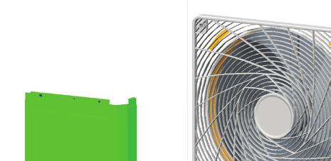
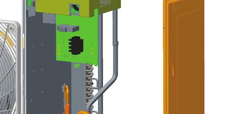

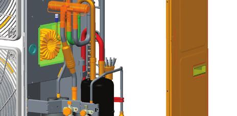
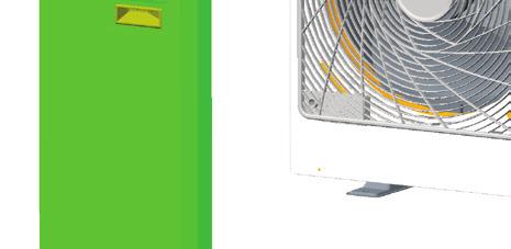
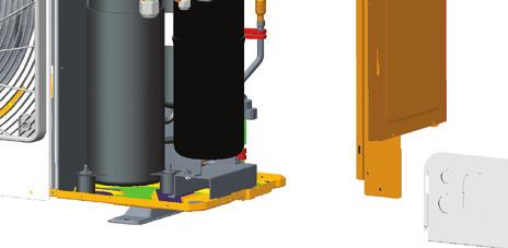
75 4 DISASSEMBLY AND ASSEMBLY PROCEDURE OF MAIN PARTS Disassembly and assembly of external casing Remark: Please first cut off the power and discharge the Freon out of the unit Operation Procedure OutdooUnit : GRS-CQ12Pd/NaB-K(O), GRS-CQ14Pd/NaB-K(O), GRS-CQ16Pd/NaB-K(O) Illustration 1) Remove the cover,front side plate and right side plate. Loosen the two tapping screws, and remove the cover, the front side plate and right side plate.[ Fig. 2] Fig. 1 Fig. 2 MAINTENANCE 72

")


![3] Fig.](/docs-images/81/84708949/images/76-7.jpg "4 73")
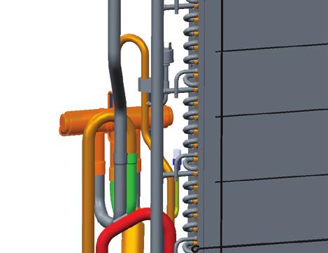

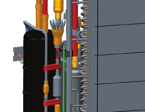

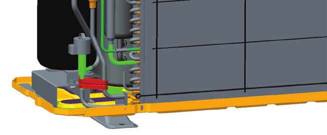

76 Air to Water Heat Pump Fig. 3 2) Remove the Cabinet. Loosen the two tapping screws, and remove the Cabinet. [See Fig. 3] Fig MAINTENANCE


![8] Fig.](/docs-images/81/84708949/images/77-14.jpg "7")
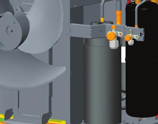
77 3) Remove the Rear Grill Loosen the two tapping screws, and remove the Rear Grill.[See Fig.5] Fig.5 4) Remove the Electric Box Assy Loosen the two tapping screws, and remove the electric box assy.[see Fig. 8] Fig.7 MAINTENANCE 74


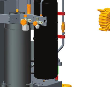

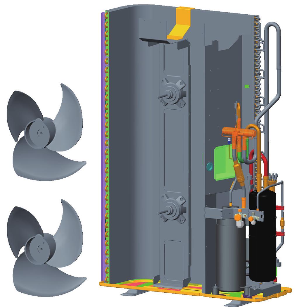

78 Fig.8 6) Remove the axial fan Loosen the ball nuts, and remove the axial fan. [See Fig. 9] Fig MAINTENANCE

![Remove the motor. [See Fig. 10] Fig.](/docs-images/81/84708949/images/79-1.jpg "10 8) Remove the 4-way valve Loosen the screws fixing the coil of 4-way valve.")

79 7) Remove the motor Loosen the screws fixing the motor support. Remove the motor support. Loosen the wire of motor, and pull it through the hole. Remove the motor. [See Fig. 10] Fig.10 8) Remove the 4-way valve Loosen the screws fixing the coil of 4-way valve. Remove the coil of 4-way valve. Unsolder the tubes connected to the 4-way valve. Remove the 4-way valve.[see Fig.11] Note: When welding, the valve should be covered by wet cloth in order to avoid the high temp. damage. Fig.11 MAINTENANCE 76

![12] Note: When welding, the valve should be covered by wet cloth in order to avoid the](/docs-images/81/84708949/images/80-1.jpg "high temp hurt. 2.Remove liquid valve Loosen the bolts fixing the liquid valve.")


80 1. Remove gas valve Loosen the bolts fixing the gas valve. Welding out the pipe connected to the gas valve [See Fig.12] Note: When welding, the valve should be covered by wet cloth in order to avoid the high temp hurt. 2.Remove liquid valve Loosen the bolts fixing the liquid valve. Welding out the pipe connected to the liquid valve [See Fig.12] Note: When welding, the valve should be covered by wet cloth in order to avoid the high temp hurt. Fig.12 9) Remove compressor and gas-liquid separator Remove the connection wire of compressor.[see Fig.13] Welding out the suction pipe and discharge pipe.[see Fig.14] Loosen the bolts fixing the compressor and Remove the compressor and gas-liquid separator. Fig MAINTENANCE

81 Fig.14 MAINTENANCE 78


![Fig. 2]](/docs-images/81/84708949/images/82-3.jpg "Fig. 2 79")
82 Indoor Unit Fig. 1 1) Front panel assy [ Fig. 2] Fig MAINTENANCE


83 2) Electric box assy [ Fig. 3] Fig. 3 3) Water pump and water flow switch [See Fig.4] Note:GRS-CQ16Pd/Na-H(I) is not equipped with the water pump. Fig. 4 MAINTENANCE 80


![Fig.5] (joint of](/docs-images/81/84708949/images/84-2.jpg "pressure gauge for")
 Fig.")


84 4) Electric heater, automatic air outlet valve and relieve valve [See Fig.5] (joint of pressure gauge for capillary shall be removed) Fig.5 5) Expansion tank [See Fig. 6] Fig.6 6) Plate-type heat exchanger [See Fig. 7] Fig MAINTENANCE
Air-to-water Heat Pump Monobloc Versati
 Change for life Air-to-water Heat Pump Monobloc Versati Engineering Data GREE ELECTRIC APPLIANCES, INC.OF ZHUHAI CONTENTS 1 Product Data... 1 1.1 Lineup... 1 1.2 Nomenclature... 1 1.3 Product Features...
C&H NORDIC Commercial 4 SERVICE MANUAL
 C&H NORDIC Commercial 4 SERVICE MANUAL CONTENTS PRODUCT...3 1 MODELS LIST... 3 1.1 Outdoor Unit.... 3 1.2 Indoor Unit.... 4 2 PRODUCT DATA.... 5 2.1 Product Data of Indoor Unit... 5 2.2 Operation Range...
Air-to-water Heat Pump Split Versati
 Air-to-water Heat Pump Split Versati Commercial AC R&D DepartmentⅠ October, 2015 Contents PRODUCT... 6 1 Product Data... 7 1.1 Lineup... 7 1.1.1 Main Unit... 7 1.1.2 Water Tank... 7 1.2 Nomenclature...
VERSATI SERIES AIR TO WATER HEAT PUMP WATER HEATER
 VERSATI SERIES AIR TO WATER HEAT PUMP WATER HEATER (GC201105- ) TTER CONDITIONERS GREE MAKING BETTER CONDITIONERS GREE MAKING BETTER CONDITIONERS GREE MAKING BETTER CONDI TECHNICAL SALES GUIDE-50Hz CAPACITY
U-MATCH SERIES DC INVERTER AIR CONDITIONERS SERVICE MANUAL
 U-MATCH SERIES DC INVERTER AIR CONDITIONERS SERVICE MANUAL T1/R410A/50Hz (GC201304 - ) CONTENTS PRODUCT... 2 1 MODELS LIST... 2 1.1 Outdoor Unit...2 1.2 Indoor Unit...3 2 NOMENCLATURE... 4 2.1 Outdoor
Wired Controller XK60
 Owner's Manual Commercial Air Conditioners Thank you for choosing Commercial Air Conditioners, please read this owner s manual carefully before operation and retain it for future reference. User Notice
CASSETTE, FLOOR&CEILING, DUCT UNITS OUTDOOR UNITS
 SERVICE MANUAL MULTI COMBI OUTDOOR AND INDOOR UNITS CASSETTE, FLOOR&CEILING, DUCT UNITS OUTDOOR UNITS (36k,42k) COMBINATION TABLE (unit: kw) MC-E18AI MC-E24AI MC-E28AI MC-E36AI 1 model 2 models 2 models
SERVICE MANUAL UNI SPLIT SERIES. ASC-xxBI, ASD-xxBI, ASF-xxBI, ASGE-xxBI, ASGE-xxBI-3
 EN SERVICE MANUAL UNI SPLIT SERIES ASC-xxBI, ASD-xxBI, ASF-xxBI, ASGE-xxBI, ASGE-xxBI-3 Original instructions IMPORTANT NOTE: Read this manual carefully before installing or operating your new air conditioning
SEMTIC HEATING
 SEMTIC HEATING www.ttshop.se Luxury Air Source Heat Pump - Touch Screen Operation Manual - AXAO-06 AXAO-08 AXAO-11 AXAO-14 AXAO-14/3 AXAO-16/3 AXAO-21/3 0 Operation instruction 1. Main page 1.1. It shows
CENTRAL AIR CONDITIONERS SUPER FREE MATCH SERIES SERVICE MANUAL. T1/R410A/50Hz ( GC )
") CENTRAL AIR CONDITIONERS SUPER FREE MATCH SERIES SERVICE MANUAL T1/R410A/50Hz ( GC201405 - ) Contents Contents... 2 PRODUCT... 2 1 MODELS LIST... 2 1.1 Outdoor Unit... 2 1.2 BU Module... 2 1.3 Indoor Unit...
CENTRAL AIR CONDITIONERS SUPER FREE MATCH SERIES SERVICE MANUAL T1/R410A/50Hz ( GC201405 - ) Contents Contents... 2 PRODUCT... 2 1 MODELS LIST... 2 1.1 Outdoor Unit... 2 1.2 BU Module... 2 1.3 Indoor Unit...
INSTALLATION AND USER MANUAL
 INSTALLATION AND USER MANUAL Thank you for choosing our product and trusting our company. This manual is to provide you with necessary information for optimal use and maintenance, please read carefully
INSTALLATION AND USER MANUAL
 INSTALLATION AND USER MANUAL Thank you for choosing inverter heat pump. This manual provides you necessary information for optimal use and maintenance, please read it carefully and keep it for subsequent
Service Manual. Multi Split Type Heat Pump Air Conditioners. Applied to: HS-9U2IM_HOS-18U2IM HS-9U11IM_HS-12U11IM_HOS-21U11IM
 Service Manual Multi Split Type Heat Pump Air Conditioners Applied to: HS-9U2IM_HOS-18U2IM HS-9U11IM_HS-12U11IM_HOS-21U11IM CONTENT 1. Product features 2. Specification 3. Dimensions 4. Refrigeration cycle
PDA20DX Air Purifying Dehumdifier Manual
 PDA20DX Air Purifying Dehumdifier Manual Index Important Safe Guards Ambient Environment For Operating Components Diagrams---Parts Names Operating Introduction---How to operate - Functions of Control Panel
SPECIFICATIONS for AIR CONDITIONING CONTROLLER ZONE CONTROL
 SPECIFICATIONS for AIR CONDITIONING CONTROLLER ZONE CONTROL 1. INTROUCTION Zone control is a two pieces fan coil thermostat available for Heat/Cool versions. Its application is for the duct type system
Warning: 230V / 1ph / 50Hz V / 3ph / 50Hz. Remarks: Make sure that you have enough power. (See page 15 Cable table)
") 1 2 Warning: - Do not place your hand or any other objects into the air outlet and fan. It could damage the heat pump and cause injuries; - In case of any abnormality with the heat pump, cut off the power
1 2 Warning: - Do not place your hand or any other objects into the air outlet and fan. It could damage the heat pump and cause injuries; - In case of any abnormality with the heat pump, cut off the power
CONTROL PANEL INSTRUCTIONS RSQ-4
 CONTROL PANEL INSTRUCTIONS RSQ-4 FOR SIRAC AIR TO WATER HEAT PUMP (SINGLE COMPRESSOR, AIR TO WATER) 1) System Configuration This system is composed of mainboard and wire control panel. 146mm Φ4 4 Mainboard
INSTALLATION AND USER MANUAL
 INSTALLATION AND USER MANUAL t Thank you for choosing Aqua inverter heat pump. This manual provides you necessary information for optimal use and maintenance, please read it carefully and keep it for subsequent
Owner's Manual. Owner's Manual. Air Conditioners
 Wired Controller XK76 Owner's Manual Owner's Manual Air Conditioners Thank you for choosing Air Conditioners, please read this owner s manual carefully before operation and retain it for future reference.if
Compact design & easy maintenance
 Compact design & easy maintenance 18 SEER MRCOOL Address: 1315 College Street Clarksville TN 37040 Email: sales@mrcool.com mrcool.com Specifications and appearance are subject to change without notice.
OPERATION MANUAL. Daikin Altherma indoor unit EKHVMRD50ABV1 EKHVMRD80ABV1 EKHVMYD50ABV1 EKHVMYD80ABV1
 OPERATION MANUAL EKHVMRD50ABV1 EKHVMRD80ABV1 EKHVMYD50ABV1 EKHVMYD80ABV1 EKHVMRD50+80ABV1 EKHVMYD50+80ABV1 CONTENTS Page 1. Definitions... 1 2. Introduction... 2 2.1. General information... 2 2.2. Scope
Air Conditioner CONTENTS
 ORDER NO. MAC0509068C2 Air Conditioner CS-F24DD1E5 CU-B24DBE5 CS-F28DD1E5 CU-B28DBE5 CS-F28DD1E5 CU-B28DBE8 CS-F34DD1E5 CU-B34DBE5 CS-F34DD1E5 CU-B34DBE8 CS-F43DD1E5 CU-B43DBE8 CS-F50DD1E5 CU-B50DBE8 CONTENTS
OWNER S MANUAL DUCTED INVERTER. (English) (SDHV SERIES)
 (SDHV SERIES)") OWNER S MANUAL DUCTED INVERTER (English) (SDHV SERIES) IMPORTANT As with any product that has moving parts or is subject to wear and tear, it is VERY IMPORTANT that you maintain your air conditioner and
OWNER S MANUAL DUCTED INVERTER (English) (SDHV SERIES) IMPORTANT As with any product that has moving parts or is subject to wear and tear, it is VERY IMPORTANT that you maintain your air conditioner and
Wired Remote Controller XK19 and Wireless Remote Controller YT1F
 and Wireless Remote Controller YT1F Owner's Manual Commercial Air Conditioners Thank you for choosing Commercial Air Conditioners, please read this owner s manual carefully before operation and retain
Technicians Manual Single Compressor
 Technicians Manual Single Compressor HAC-FF-D WALL PAD Operating Manual Version PCB Version V2.3.5 Version wall pad Version Manual Page 1 Contents 1. Main features 2. Main technical data 3. Wall pad 4.
Operating Functions Temperature Parameters
 Operating Functions Temperature Parameters Room set temperature (T set) Room ambient temperature (T amb) Fundamental Functions After powered on, no matter when the compressor is started, the time interval
Operation manual. Daikin Altherma Low temperature split EHBH04CBV EHBH08CBV EHBH11CBV EHBH16CBV
 EHBH04CBV EHBH08CBV EHBH11CBV EHBH16CBV EHVH04S18CBV EHVH08S18CBV EHVH08S26CBV EHVH11S26CBV EHVH16S26CBV English Table of contents Table of contents 1 About this document 2 2 About the system 2 2.1 Components
DC inverter Outdoor-air Processing unit (GC )
") DC inverter Outdoor-air Processing unit (GC201109- ) ER CONDITIONERS GREE MAKING BETTER CONDITIONERS GREE MAKING BETTER CONDITIONERS GREE MAKING BETTERNDITINER TECHNICAL SALES GUIDE-50Hz CAPACITY RANGE:14~56kW
DC inverter Outdoor-air Processing unit (GC201109- ) ER CONDITIONERS GREE MAKING BETTER CONDITIONERS GREE MAKING BETTER CONDITIONERS GREE MAKING BETTERNDITINER TECHNICAL SALES GUIDE-50Hz CAPACITY RANGE:14~56kW
FAN COILS wall mounted
 SERVICE MANUAL FAN COILS wall mounted SF-51H, SF-68H, SF-85H PRODUCT MODELS LIST Model Name Cooling Capacity (W) Product Code Air Flow (m 3 /h) Power Supply (V,Ph,Hz) Remarks SF-51H 2700 EM55001260 550
Operation manual. Daikin Altherma ground source heat pump EGSQH10S18AA9W. Operation manual Daikin Altherma ground source heat pump.
 EGSQH0S8AA9W English Table of contents Table of contents About this document About the system Components in a typical system layout Operation Overview: Operation The user interface at a glance Buttons
Operation manual. Daikin Altherma ground source heat pump EGSQH10S18AA9W. Operation manual Daikin Altherma ground source heat pump.
 English Table of contents Table of contents About this document About the system. Components in a typical system layout... 3 Operation 3 3. Overview: Operation... 3 3. The user interface at a glance...
OPERATION MANUAL. Indoor unit for hot water heat pump system and options EKHBH016AB EKHBX016AB
 OPERATION MANUAL Indoor unit for hot water heat pump system and options EKHBH016AB EKHBX016AB EKHBH016AB*** EKHBX016AB*** Indoor unit for hot water heat pump system and options CONTENTS Page Introduction...1
S-Therm Air to Water Heat Pumps
 S-Therm Air to Water Heat Pumps AIR TO WATER HEAT PUMP Air to water heat pump Nowadays, people are increasingly focusing on the cost of heating as well as on environmental issues. Traditional heating systems
Installation Instructions / User s Manual TSTAT0406 and TSTAT0408
 997-060180-5 Installation Instructions / User s Manual TSTAT0406 and TSTAT0408 4 HEAT 2 COOL DUAL FUEL TSTAT0406 & TSTAT0408-4 WIRE CAPABLE THERMOSTAT (NAXA00201DB Daughter Board sold separately) LEFT
Operation manual. Daikin Altherma low temperature monobloc EBLQ05CAV3 EBLQ07CAV3 EDLQ05CAV3 EDLQ07CAV3
 EBLQ05CAV3 EBLQ07CAV3 EDLQ05CAV3 EDLQ07CAV3 English Table of Contents Table of Contents 1 About this document 2 2 About the system 2 2.1 Components in a typical system layout... 2 3 Operation 3 3.1 Overview:
OPERATION MANUAL. Indoor unit for air to water heat pump and sanitary warm water tank for air to water heat pump system EKHBH007A EKHBX007A
 OPERATION MANUAL Indoor unit for air to water heat pump and sanitary warm water tank for air to water heat pump system EKHBH007A EKHBX007A EKHBH007A*** EKHBX007A*** Indoor unit for air to water heat pump
SERVICE MANUAL. Inverter Wall Mounted Single Split. MODELS Cooling Only. Heatpump SM-5WM-Y-NA-B1
 SERVICE MANUAL Inverter Wall Mounted Single Split MODELS Cooling Only FTKB09AXVJU FTKB12AXVJU FTKB18AXVJU FTKB24AXVJU FTKN09AXVJU FTKN12AXVJU FTKN18AXVJU FTKN24AXVJU Heatpump FTXB09AXVJU FTXB12AXVJU FTXB18AXVJU
Operation manual. Daikin Altherma Low temperature split EHBH04CB EHBH08CB EHBH11CB EHBH16CB EHBX04CB EHBX08CB EHBX11CB EHBX16CB
 EHBH04CB EHBH08CB EHBHCB EHBH6CB EHBX04CB EHBX08CB EHBXCB EHBX6CB EHVH04S8CB EHVH08S8CB EHVH08S6CB EHVHS8CB EHVHS6CB EHVH6S8CB EHVH6S6CB EHVX04S8CB EHVX08S8CB EHVX08S6CB EHVXS8CB EHVXS6CB EHVX6S8CB EHVX6S6CB
OPERATION MANUAL. Packaged air-cooled water chillers and packaged reversible air to water heatpumps EWAQ009ACV3 EWAQ010ACV3 EWAQ011ACV3
 OPERATION MANUAL Packaged air-cooled water chillers and packaged reversible air to EWAQ009ACV3 EWAQ010ACV3 EWAQ011ACV3 EWYQ009ACV3 EWYQ010ACV3 EWYQ011ACV3 EWAQ009ACW1 EWAQ011ACW1 EWAQ013ACW1 EWYQ009ACW1
GREE ELECTRIC APPLIANCES, INC. OF ZHUHAI
 Change for life Models: GFH(09)EA-K6DNA1B/I GFH(12)EA-K6DNA1B/I GFH(18)EA-K6DNA1B/I GFH(21)EA-K6DNA1B/I Models: GFH(24)EA-K6DNA1B/I (Refrigerant R32) GREE ELECTRIC APPLIANCES, INC. OF ZHUHAI Table of Contents
Wired controller KJR-08B/BE. Run. Fault. TB Tot. Out. Query. Heat. Net-On. Turn-On Mode
 R0A (kw-0kw) 0Hz KJR-0B/BE is a human-machine interaction(hmi) used for the communication between chiller operator and main board on the chiller itself. The setting and operation order can be send to the
SERVICE MANUAL MUFZ-KJ50VE - E1, E2, ER1, ER2, ET1, ET2 MUFZ-KJ35VE OUTDOOR UNIT. No. OBH667. Models HFC
 Revision D: MUFZ-KJ25VE - E2, ER2, ET2, MUFZ- KJ35VE - E2, ER2, ET2 and MUFZ- KJ50VE - E2, ER2, ET2 have been added. Please void OBH667 REVISED EDITION-C. OUTDOOR UNIT SERVICE MANUAL HFC utilized R410A.
Ducted inverter reverse cycle air conditioning
 Ducted inverter reverse cycle air conditioning What is ducted inverter reverse cycle air conditioning? Ducted inverter reverse cycle air conditioning is an ideal solution for whole-of-home or office cooling
WORLD LARGEST Air Conditioners Manufacturer PRODUCT CATALOGUE GREE MALAYSIA SDN BHD ( M)
") WORLD LARGEST Air Conditioners Manufacturer PRODUCT CATALOGUE GREE MALAYSIA SDN BHD (1132718-M) WALL MOUNTED SPLIT UNIT LOMO N Series WALL MOUNTED SPLIT UNIT R410A Eco-friendly Refrigerant Quiet Fast Cooling
WORLD LARGEST Air Conditioners Manufacturer PRODUCT CATALOGUE GREE MALAYSIA SDN BHD (1132718-M) WALL MOUNTED SPLIT UNIT LOMO N Series WALL MOUNTED SPLIT UNIT R410A Eco-friendly Refrigerant Quiet Fast Cooling
Hot Water Heating Systems
 Hot Water Heating Systems Find out more at www.greeonline.com Key Wide Range of Operation Conditions Heating -26 C 46 C Features The Ultra Hot Water system is specifically designed to be flexible in its
Before using your air conditioner, please read this manual carefully and keep it for future reference. ACDC12B
 Before using your air conditioner, please read this manual carefully and keep it for future reference. ACDC12B INVERTER SPLIT-TYPE ROOM AIR CONDITIONER User and Remote Control Manual Read This Manual Inside
VMI-1102-A SERVICE MANUAL AIRCONDITIONER DC INVERTER MULTI TYPE MSV1I-09HRDN1-M TAS-09MVHN TAS-12MVHN INDOOR VERTU DC INVERTER MULTI SERIES
 VMI-1102-A SERVICE MANUAL AIRCONDITIONER DC INVERTER MULTI TYPE MSV1I-09HRDN1-M TAS-09MVHN TAS-12MVHN INDOOR VERTU DC INVERTER MULTI SERIES CONTENTS 1. Precaution... 1 1.1 Safety Precaution...1 1.2 Warning...1
BTU Units WORKING PROGRAM MANUAL
 9000-24000BTU Units WORKING PROGRAM MANUAL SUMMARIZE FUNCTIONS & OPERATION MODES TIMER, SLEEP MODE, FAN SPEED PROTECTION FUNCTIONS EMERGENCY SWITCH TEST GUIDE MEMORY FUNCTIONS SUMMARIZE The Operation Modes
All DC Inverter Multi VRF
 All DC Inverter Multi VRF In 2012, Gree highly promoted GMV5 All DC Inverter Multi VRF New breakthrough in comfort ability, intelligent control and design. Eight prominent advantages More powerful product
WIRED REMOTE CONTROLLER
 WIRED REMOTE CONTROLLER USER REFERENCE GUIDE BRC073A1 Thank you for purchasing the wired remote controller. This manual describes safety precautions required for the use of the product. Read this manual
OWNER S MANUAL. Vintage Classic HEAT COOL models. Proudly Made in the USA
 OWNER S MANUAL Vintage Classic HEAT COOL models Proudly Made in the USA support@aquacomfort.com www.aquacomfort.com/service-and-support 888-475-7443 Manufacturing High Quality, High Efficiency Heat Pump
High Wall Split Systems Cool Only 9K - 12K - 18K - 24K. Auto. Auto. Fan Speed. Smart LCD Wireless Control. Auto Mode.
 HFC4 1 0 A 0-40V ~, 0Hz 1Ph High Wall Split Systems Cool Only 9K - 1K - 18K - 4K R-410A IAQ $ Auto Auto Fan Speed Timer s Easy Flexible Installation Smart LCD Wireless Control Auto Mode Auto Restart Easy
OPERATING INSTRUCTIONS
 COMFORT CONTROL CENTER 2 THERMOSTAT OPERATING INSTRUCTIONS PROGRAMMABLE THERMOSTAT MODEL 3314080.000 BLACK 3314080.015 WHITE USA SERVICE OFFICE Dometic Corporation 1120 North Main Street Elkhart, IN 46514
V ~, 50Hz 1Ph. High Wall Split Systems Heat Pump 9K - 12K - 18K - 24K - 28K. Auto. Auto Fan Speed. Auto. Smart LCD Wireless Control.
 HFC4 1 0 A 0-40V ~, 0Hz 1Ph High Wall Split Systems Heat Pump 9K - 1K - 18K - 4K - 8K R-410A Compressor Super Quiet AMS Anti-dust Filters Auto Fan Speed Timer Functions Defrost Protection Smart LCD Wireless
Owner s Manual AIR TO WATER HEAT PUMP. Hydro Unit HWS-804XWHM3-E HWS-804XWHT6-E HWS-804XWHT9-E HWS-1404XWHM3-E HWS-1404XWHT6-E HWS-1404XWHT9-E
 AIR TO WATER HEAT PUMP Hydro Unit Model name: HWS-804XWHM3-E HWS-804XWHT6-E HWS-804XWHT9-E HWS-1404XWHM3-E HWS-1404XWHT6-E HWS-1404XWHT9-E English Thank you very much for purchasing TOSHIBA Air to Water
R410A. WALL MOUNTEDtype INVERTER SPLIT TYPE ROOM AIR CONDITIONER. Models Indoor unit Outdoor unit AOYG07LEC AOYG09LEC AOYG12LEC AOYG14LEC
 SERVICE INSTRUCTION SPLIT TYPE ROOM AIR CONDITIONER WALL MOUNTEDtype INVERTER Models Indoor unit Outdoor unit ASYG07LECA ASYG09LECA ASYG12LECA ASYG14LECA AOYG07LEC AOYG09LEC AOYG12LEC AOYG14LEC R410A CONTENTS
OPERATING MANUAL AIR CONDITIONER DUCT TYPE. ART Series KEEP THIS MANUAL FOR FUTURE REFERENCE FUJITSU GENERAL LIMITED P/N
 OPERATING MANUAL AIR CONDITIONER DUCT TYPE ART Series KEEP THIS MANUAL FOR FUTURE REFERENCE FUJITSU GENERAL LIMITED P/N9374379293-02 CONTENTS SAFETY PRECAUTIONS... 1 NAME OF PARTS... 2 PREPARATORY OPERATION...
WIRED REMOTE CONTROLLER
 WIRED REMOTE CONTROLLER OPERATION MANUAL BRCE6 Thank you for purchasing this product. This manual describes safety precautions required for the use of the product. Read this manual carefully and be sure
Service Manual. Room Air Conditioner Split Wall-Mounted Type. Applies to: HSG-09HRN1 HSG-12HRN1 HSG-18HRN1 HSG-24HRN1
 Service Manual Room Air Conditioner Split Wall-Mounted Type Applies to: HSG-09CRN1 HSG-12CRN1 HSG-18CRN1 HSG-24CRN1 HSG-09HRN1 HSG-12HRN1 HSG-18HRN1 HSG-24HRN1 NOTE: Please read this first before servicing
WIRED REMOTE CONTROLLER
 WIRED REMOTE CONTROLLER USER REFERENCE GUIDE BRC073A4 Thank you for purchasing the wired remote controller. This manual describes safety precautions required for the use of the product. Read this manual
PAC BT LOW TEMPERATURE HEAT PUMP
 PAC BT LOW TEMPERATURE HEAT PUMP Just feel well COP up to. EER up to. PAC BT -7 kw A ++ + PRODUCTS Cooling and heating mode. Monobloc system. Available in 3PH (sizes 1 to 1). High flexibily due to DC Inverter
Contents. Part 1 General Information...2 Part 2 Outdoor units...7 Part 3 Installation...63 Part 4 Controller...79
 MCAC-TSM-2008-02 Contents Part 1 General Information...2 Part 2 Outdoor units...7 Part 3 Installation...63 Part 4 Controller...79 Contents i MCAC-TSM-2008-02 Introduction Introduction Midea Mini Unitary
OWNER S MANUAL DLFCAB / DLFCHB / DLFDAB / DLFDHB High Wall Ductless System Sizes 09 36
 OWNER S MANUAL DLFCAB / DLFCHB / DLFDAB / DLFDHB High Wall Ductless System Sizes 09 36 TABLE OF CONTENTS PAGE SAFETY PRECAUTIONS... 2 GENERAL... 2 INDOOR UNIT PART NAMES... 3 REMOTE CONTROL PART NAMES...
Operating Instructions High-spec Wired Remote Controller
 Operating Instructions High-spec Wired Remote Controller Model No. CZ-RTC Installation Instructions Separately Attached. ENGLISH Before operating the unit, read these operating instructions thoroughly
WORKING PROGRAM. Heating dehumidifying cooling T 27
 I. Functions and Operation Modes WORKING PROGRAM The operation modes of the unit run like the following: Auto cooling dehumidifying heating --------------------------------------- Note: Cooling only unit
AIR TO WATER HEAT PUMP USER MANUAL
 AIR TO WATER HEAT PUMP Domestic Hot Water Series USER MANUAL Installation Operation Maintenance MODELS: AKRS-35B/N-L AKRS-50B/N-L AKRS-7B/N-L AKRS-90B/N-L READ AND SAVE THIS MANUAL V.01304 CONTENTS 1.
OWNER S MANUAL HIGH WALL INVERTER. (English) (MSHVD1S SERIES)
 (MSHVD1S SERIES)") OWNER S MANUAL HIGH WALL INVERTER (English) (MSHVD1S SERIES) IMPORTANT As with any product that has moving parts or is subject to wear and tear, it is VERY IMPORTANT that you maintain your air conditioner
OWNER S MANUAL HIGH WALL INVERTER (English) (MSHVD1S SERIES) IMPORTANT As with any product that has moving parts or is subject to wear and tear, it is VERY IMPORTANT that you maintain your air conditioner
OWNER S MANUAL. R 410A Ductless Split System Air Conditioner and Heat Pump
 R 410A Ductless Split System Air Conditioner and Heat Pump Models DLC4(A/H) Outdoor Unit, DLF4(A/H) Indoor Unit Sizes 9K, 12K, 18K, 24K, 30K and 36K Please read the operating instructions and safety precautions
SERVICE MANUAL MUZ-FH25VE MUZ-FH35VE MUZ-FH50VE OUTDOOR UNIT. No. OBH624. Models HFC. Revision A: MUZ-FH50VE- E1 has been added. Please void OBH624.
 SPLIT-TYPE AIR CONDITIONERS Revision A: MUZ-FH50VE- E1 has been added. Please void OBH624. OUTDOOR UNIT SERVICE MANUAL HFC utilized R410A. OBH624 REVISED EDITION-A Models MUZ-FH25VE MUZ-FH35VE MUZ-FH50VE
TAC-09CS/K TAC-12CS/K TAC-18CS/K TAC-24CS/K TAC-07CHS/K TAC-09CHS/K TAC-12CHS/K TAC-18CHS/K TAC-24CHS/K
 TCL WALL MOUNTED SPLIT-TYPE AIR CONDITIONERS SERVICE MANUAL No.TE040427 Models TAC-07CS/K TAC-09CS/K TAC-2CS/K TAC-8CS/K TAC-24CS/K TAC-07CHS/K TAC-09CHS/K TAC-2CHS/K TAC-8CHS/K TAC-24CHS/K CONTENTS. IMPORTANT
Air source heat pump. (water heating module-18kw)
") Air source heat pump (water heating module-8kw) User Manual Before use Safety precautions 2 Features and advantages 3 Main components 4 Outlines and dimensions 5 Working principles 6 Technical data 7
Air source heat pump (water heating module-8kw) User Manual Before use Safety precautions 2 Features and advantages 3 Main components 4 Outlines and dimensions 5 Working principles 6 Technical data 7
Product Data FEATURES AND BENEFITS. QHF 50Hz Heat Pump Inverter Single Phase 2.5kW to 8.0kW
 0Hz Heat Pump Inverter Single Phase.kW to 8.0kW turn to the experts Product Data FEATURES AND BENEFITS AVAILABLE SIZES: Nominal capacity are available from.kw through 8.0kW to meet the needs of residential
MA Remote Controller PAR-31MAA
 English Deutsch CITY MULTI Control System and Mitsubishi Mr. Slim Air Conditioners MA Remote Controller PAR-MAA Simple Operation Manual Français Español Italiano Nederlands Português Türkçe eský Slovenský
Midea R410A Tropical ClimaCreator Series Rooftop Package 220V 3Ph 60Hz Technical Manual
 Midea R410A Tropical ClimaCreator Series Rooftop Package 220V 3Ph 60Hz Technical Manual Midea reserves the right to discontinue, or change specification or designs at any time without notices and without
Westinghouse. Split System Inverter Series. Service Manual
 Westinghouse Split System Inverter Series Service Manual Model: WIWPK/WCHPK Range: 2.6kw 7.6kw CONTENTS 1. Precaution... 1 1.1 Safety Precaution... 1 1.2 Warning... 1 2. Function... 5 3. Dimension... 6
SERVICE MANUAL MUY-GL24NA - U1. No. OBH733. Models HFC. Revision B: REVISED EDITION-B R410A
 Revision B: MUZ-GL09NA- U8 and MUZ-GL09NAH- U8 have been added. Please void OBH733 REVISED EDITION-A. OUTDOOR INDOOR UNIT UNIT SERVICE MANUAL HFC utilized R410A. OBH733 REVISED EDITION-B Models MUZ-GL09NA
SERVICE MANUAL OUTDOOR UNIT MUZ-FH06NAH MUZ-FH09NAH MUZ-FH06NA MUZ-FH09NA MUZ-FH09NA - 1 MUZ-FH09NAH - 1 MUZ-FH12NA MUZ-FH12NAH
 Revision D: Capacity corrections have been corrected [7-1. 2), 3)]. OBH684 REVISED EDITION-C is void. OUTDOOR UNIT SERVICE MANUAL HFC utilized R410A. OBH684 REVISED EDITION-D Models MUZ-FH06NA MUZ-FH09NA
SPLIT TYPE ROOM AIR CONDITIONER. WALL MOUNTEDtype INVERTER. Models Indoor unit Outdoor unit AOU 9RLFW1 AOU12RLFW1 ASU 9RLF1 ASU12RLF1 R410A
 SERVICE INSTRUCTION SPLIT TYPE ROOM AIR CONDITIONER WALL MOUNTEDtype INVERTER Models Indoor unit Outdoor unit ASU 9RLF ASURLF AOU 9RLFW AOURLFW R40A CONTENTS. DESCRIPTION OF EACH CONTROL OPERATION. COOLING
Service Manual. Multi-Pipe VRF Outdoor Units VOM0355H2RE508 VOM0362H2RE Innovair Corporation. All Rights Reserved.
 Service Manual Multi-Pipe VRF Outdoor Units VOM0355H2RE508 VOM0362H2RE509 2015 Innovair Corporation. All Rights Reserved. www.innovair.com/support Contents PRODUCT... 1 1 MODELS LIST... 2 1.1 Outdoor Unit...
Updated: 17/03/2010 ELECTROLUX. CAREL ir33. Quick reference Handbook. Ver. 1.1 Eng. Pag.1/12
 CAREL ir33 Quick reference Handbook Pag.1/12 MAIN FEATURES OF THE INSTRUMENT USER INTERFACE 1. ON/OFF switch button UP button to increase temperature values 2. DOWN button to decrease values - Activates/deactivates
EVI Scroll Air To Water Heat Pumps
 AIR TO WATER HEAT PUMPS 2013 heart of your home H E A T P U M P S Air To Water Heat Pumps Nowadays, people are increasingly focusing on the costs of heating as well as on environmental issues. Traditional
OWNER S MANUAL HIGH WALL INVERTER. (English) (BSHVD1S SERIES)
 (BSHVD1S SERIES)") OWNER S MANUAL HIGH WALL INVERTER (English) (BSHVD1S SERIES) IMPORTANT As with any product that has moving parts or is subject to wear and tear, it is VERY IMPORTANT that you maintain your air conditioner
OWNER S MANUAL HIGH WALL INVERTER (English) (BSHVD1S SERIES) IMPORTANT As with any product that has moving parts or is subject to wear and tear, it is VERY IMPORTANT that you maintain your air conditioner
1/8. Field settings table [6.8.2] =... ID66F3. Applicable indoor units *HYHBH05AAV3 *HYHBH08AAV3 *HYHBX08AAV3. Notes - 4P E
![1/8. Field settings table [6.8.2] =... ID66F3. Applicable indoor units *HYHBH05AAV3 *HYHBH08AAV3 *HYHBX08AAV3. Notes - 4P E](/thumbs/75/71719734.jpg "1/8. Field settings table [6.8.2] =... ID66F3. Applicable indoor units *HYHBH05AAV3 *HYHBH08AAV3 *HYHBX08AAV3. Notes - 4P E") /8 [6.8.2] =... ID66F3 Applicable indoor units *HYHBH5AAV3 *HYHBH8AAV3 *HYHBX8AAV3 Notes - 4P35373-E - 27.2 2/8 User settings Preset values Room temperature 7.4.. Comfort (heating) R/W [3-7]~[3-6], step:
/8 [6.8.2] =... ID66F3 Applicable indoor units *HYHBH5AAV3 *HYHBH8AAV3 *HYHBX8AAV3 Notes - 4P35373-E - 27.2 2/8 User settings Preset values Room temperature 7.4.. Comfort (heating) R/W [3-7]~[3-6], step:
Air-to-Water Heat Pump (50Hz, R410A) 5BPM0-01G (Replace: 5BPM0-01F)
 5BPM0-01G (Replace: 5BPM0-01F)") Air-to-Water Heat Pump (50Hz, R410A) 5BPM0-01G (Replace: 5BPM0-01F) P/No. : MFL66101106 CONTENTS Part 2. Design and installation Part 3. Accessories 1. Features 2. Nomenclature 3. List of functions 4.
Air-to-Water Heat Pump (50Hz, R410A) 5BPM0-01G (Replace: 5BPM0-01F) P/No. : MFL66101106 CONTENTS Part 2. Design and installation Part 3. Accessories 1. Features 2. Nomenclature 3. List of functions 4.
AQUATROL Zone Synchronizing Universal Injection/Mixing Boiler Reset Controls AQ252
 AQUATROL Zone Synchronizing Universal Injection/Mixing Boiler Reset Controls AQ252 USER OPERATION AND MAINTENANCE WARNING Risk of electrical shock. Can cause severe injury, property damage or death. Only
Product Features Technical Training 2007
 Product Features Product Features Less foot print occupied Less space required. Product Features Made of AISI 316 Stainless Steel High heat exchange efficiency Product Features New Technology BPHE True
Submittal Data: LIVS09HP230V1B. Job Name Location Date. Submitted To. Cool Quiet Comfort & more 9,000 BTU/H (208/230V) Wall Mounted Heat Pump System
 Wall Mounted Heat Pump System") Submittal Data: Cool Quiet Comfort & more 9,000 BTU/H (208/230V) Wall Mounted Heat Pump System Job Name Location Date Purchaser Engineer Submitted To For Unit Designation Schedule No. GENERAL FEATURES
Submittal Data: Cool Quiet Comfort & more 9,000 BTU/H (208/230V) Wall Mounted Heat Pump System Job Name Location Date Purchaser Engineer Submitted To For Unit Designation Schedule No. GENERAL FEATURES
SERVICE MANUAL MUZ-DM25VA - E1, ER1, ET1 MUZ-DM35VA - E1, ER1, ET1 OUTDOOR UNIT. No. OBH751. Models HFC R410A
 OUTDOOR UNIT SERVICE MANUAL HFC utilized R410A. Models MUZ-DM25VA - E1, ER1, ET1 MUZ-DM35VA - E1, ER1, ET1 Indoor unit service manual MSZ-DM VA Series (OBH750) CONTENTS 1. TECHNICAL CHANGES 2 2. PART NAMES
WALL MOUNTED UNITS SDH W SDH W SDH W SDH W
 WALL MOUNTED UNITS Technical Dossier WALL MOUNTED UNITS SDH 14-026 W SDH 14-036 W SDH 14-051 W SDH 14-065 W 2010 1- CONTENTS 1- Contents... 2 2- Technical specifications... 3 3- Temperature by capacities...
Condensing Unit Service Manual (T1/R410a/60Hz)
") GREE COMMERCIAL AIR CONDITION DUCT TYPE SPLIT AIR CONDITIONER Condensing Unit Service Manual (T/R40a/60Hz) GREE ELECTRIC APPLIANCES INC. OF ZHUHAI CONTENTS PRODUCT... 2 MODELS LIST... 2 2 NOMENCLATURE...
GREE COMMERCIAL AIR CONDITION DUCT TYPE SPLIT AIR CONDITIONER Condensing Unit Service Manual (T/R40a/60Hz) GREE ELECTRIC APPLIANCES INC. OF ZHUHAI CONTENTS PRODUCT... 2 MODELS LIST... 2 2 NOMENCLATURE...
CENTRAL AIR CONDITIONERS MINI CHILLER SERVICE MANUAL
 CENTRAL AIR CONDITIONERS MINI CHILLER SERVICE MANUAL T/R40A/50Hz (GC2004) CONTENTS PRODUCT...2 MODELS LIST...2. Split Type...2.2 Integral Type...3 2 NOMENCLATURE...3. Split Type...3.2 Integral Type...4
Service Manual & Installation Manual
 GE Consumer & Industrial Appliances Service Manual & Installation Manual Split System Air Conditioner Model numbers: GE AIR F24 GE AIR F34 GE AIR F41 1 2 3 Introduction and Features Model Remarks GE AIR
COMPACT PORTABLE AIR CONDITIONER USER MANUAL
 COMPACT PORTABLE AIR CONDITIONER USER MANUAL Thank you for choosing ElectriQ Please read this user manual before using this innovative Air Conditioner and keep it safe for future reference. Visit our page
15A Operating Range Communication Wire Size 18-2 AWG / 300V THHN Cooling (Max) 118 F (48 C)
 118 F (48 C)") Innovative Ductless Mini Split Solution Job Name Location Date Purchaser Engineer Submitted To For Unit Designation Schedule No. GENERAL FEATURES -Multi-Speed Fan -4-way Discharge Air -Swing Louvers -Wireless
Innovative Ductless Mini Split Solution Job Name Location Date Purchaser Engineer Submitted To For Unit Designation Schedule No. GENERAL FEATURES -Multi-Speed Fan -4-way Discharge Air -Swing Louvers -Wireless
INSTALLATION AND USER MANUAL
 Swimming Pool Heat Pump Swimming Pool Heat Pump INSTALLATION AND USER MANUAL Thank you for choosing our product and trusting our company. This manual is to provide you with necessary information for optimal
TECHNICAL SERVICE DEPARTMENT Technical Service Bulletin Heat Pump Water Heater (Generation 4) Troubleshooting (Effective 1 Nov 2016)
 Troubleshooting (Effective 1 Nov 2016)") No Power,, Fan or Compressor Nothing happens at all. No compressor motor; no fan; no display. 1. See use and care manuals to turn unit ON and set operating MODE. 2. Check for the presence of power at the
No Power,, Fan or Compressor Nothing happens at all. No compressor motor; no fan; no display. 1. See use and care manuals to turn unit ON and set operating MODE. 2. Check for the presence of power at the
DESIGN & TECHNICAL MANUAL
 AIR CONDITIONER Wall Mounted type DESIGN & TECHNICAL MANUAL INDOOR AS A09LEC AS A12LEC OUTDOOR AO R09LECN AO R12LECN 1.INDOOR UNIT : AS A09LEC AS A12LEC DTR_AS047E_01 2010.10.05 1. INDOOR UNIT CONTENTS
- Data Brochure Boiler Control 274
 - Data Brochure Boiler Control 274 274_D 03/17 The Boiler Control 274 operates up to four on/off boilers to provide outdoor reset operation, domestic hot water and setpoint operation with priority. When
Inverter Swimming Pool Heat Pump
 P Inverter Swimming Pool Heat Pump Content I. Application... 2 II. Features... 2 III. Technical Parameter... 3 IV. Dimension... 4 V. Installation instruction... 5 VI. Operation instruction... 9 VII. Testing...
Submittal Data: VIR12HP230V1B. Job Name Location Date. Submitted To
 Submittal Data: Innovative Ductless solutions 12,000 BTU/H (208/230V) Wall Mounted Heat Pump System Job Name Location Date Purchaser Engineer Submitted To For Unit Designation Schedule No. GENERAL FEATURES