Contents. Part 1 General Information...2 Part 2 Outdoor units...7 Part 3 Installation...63 Part 4 Controller...79
|
|
|
- Alexia Griffin
- 6 years ago
- Views:
Transcription
1 MCAC-TSM Contents Part 1 General Information...2 Part 2 Outdoor units...7 Part 3 Installation...63 Part 4 Controller...79 Contents i
2

3 MCAC-TSM Introduction Introduction Midea Mini Unitary Chiller is air-cooled chiller and heat pump system, the chiller itself built in with water pump, expansion tank, plate heat-exchanger; it is very simple for installer to install such kind of system. Expansion Tank Pressure Difference Switch Plate Heat-exchanger Water Pump Introduction 1
4 General Information MCAC-TSM Part 1 General Information 1. Model Names of Outdoor Units External Appearance Nomenclature Features General Information
5 MCAC-TSM Model Names of Outdoor Units 1. Model Names of Outdoor Units Model Refrigerant Capacity Power Supply(V-ph-Hz) MGC-F05W/N1 R410A 5.0kW 220~ MGC-F07W/N1 R410A 7.2kW 220~ MGC-F09W/N1 R410A 9.0kW 220~ MGC-F10W/N1 R410A 10.5kW 220~ MGC-F10W/SN1 R410A 10.5kW 380~ MGC-F12W/SN1 R410A 12.0kW 380~ MGC-F14W/SN1 R410A 14.0kW 380~ MGC-F16W/SN1 R410A 16.0kW 380~ General Information 3

N1 MGC-F12W/SN1 MGC-F14W/SN1")
6 External Appearance 2. External Appearance MCAC-TSM MGC-F05W/N1 MGC-F07W/N1 MGC-F09W/N1 MGC-F10W/(S)N1 MGC-F12W/SN1 MGC-F14W/SN1 MGC-F16W/SN1 4 General Information
7 MCAC-TSM Nomenclature Nomenclature MGC - F 14 W / S N1 Refrigerant N1 R410A Power Supply S: V, 50Hz, 3ph --: V, 50Hz, 1ph Outdoor Unit Capacity(14kW) F: Fixed Speed Type Midea Mini Unitary Chiller General Information 5


8 Features MCAC-TSM Features 1. Adopts R410A refrigerant, friendly to our environment. 2. Compact design: built-in with water pump and expansion tank, only need to connect the water pipe, making simple installation. 3. Built-in with emergency switch: switch off the unit manually in any emergency case. Water pressure gauge: Inspect the water pressure any time Emergency switch: Stop the chiller directly by the switch in any urgent case Controller: Control interface of the chiller; Working status inspection and error display. 4. Built-in with water pressure gauge: inspect water pressure all the time. 5. Flexible control: built-in with controller inside the chiller and can be controlled in the room by remote control keyboard. 6. Built-in with voltage protection, current protection, anti-freezing protection, water flow protection and so on, guarantees the system work safety. 6 General Information
9 MCAC-TSM Outdoor units Part 2 Outdoor units 1. Specification Dimensions (unit: mm) Service Space (unit: mm) Piping Diagram Wiring Diagrams Electric Characteristics Capacity Tables Operation Limits Sound Level Exploded View Troubleshooting...52 Outdoor units 7
10 Specification MCAC-TSM Specification Model MGC-F05W/N1 MGC-F07W/N1 Power supply V-Ph-Hz , 1, , 1, 50 Cooling Capacity kw Input W Heating Capacity kw Input W Max. input consumption W Max. input current A Starting current A Model PA225X2CS-4KU1 PA330X3CS-4MU1 Type ROTARY ROTARY Brand Midea-Toshiba Midea-Toshiba Capacity Btu/h Compressor Outdoor fan motor Outdoor coil Water pump Input W Rated current (RLA) A Locked rotor Amp (LRA) A Thermal protector Inner Inner Capacitor uf 50uF/440V-450V 55uF/450V Refrigerant oil ml ESTER OIL VG74, 750 ESTER OIL VG74, 1100 Model YDK120-8U YDK120-8U Type AC motor AC motor Brand Welling Welling Input (Hi/Lo) W Capacitor uf 6uF/450V 6uF/450V Speed (Hi/Lo) r/min Number of rows 1 1 Tube pitch(a) row pitch(b) mm Fin spacing mm Fin type Hydrophilic aluminium foil Hydrophilic aluminium foil Tube outside dia. and type mm φ7.94 φ7.94 Inner grooved copper tube Inner grooved copper tube Coil length height width mm Number of circuits 4 7 Type RS15/6-3-WILO RS15/6-3-WILO Input (H/M/L) W 93/67/46 93/67/46 Outdoor air flow m 3 /h Throttle Capillary Capillary Outdoor noise level (sound pressure) db(a) Water flow volume m 3 /h The plate heat-exchanger water pressure drop kpa The Max. and Min. water inlet pressure kpa 500/ /150 Dimension (W H D) mm Outdoor unit Packing (W H D) mm Net/ Gross weight kg 83/89 94/100 Refrigerant Type R410A R410A type/quantity Charged volume g Power wiring mm Connection wiring Signal wiring (connect to wired control) mm Pipe diameter Water inlet/outlet mm R1 R1 Control Wired controller Wired controller Ambient temp. Cooling: 10 ~43 ; Heating: Nominal capacity is based on the following conditions: 1. Condenser air in 35. Evaporator water in/out 12/7 2. Evaporator air in 7 85% R.H., Condenser water in/out 40/45 3. The two types of oil are equivalents 4. At 1m in open field fan side (sound pressure) 5. The maximum and minimum operating pressure values refer to the activation of the pressure switches 8 Installation
11 MCAC-TSM Outdoor units Model MGC-F09W/N1 MGC-F10W/N1 Power supply V-Ph-Hz , 1, , 1, 50 Capacity kw 9.0 Cooling 10.5 Input W Capacity kw 9.5 Heating 12 Input W Max. input consumption W Max. input current A Starting current A Model ZP50K3E-PFZ-522 ZP50K3E-PFZ-522 Type SCROLL SCROLL Brand Copeland Copeland Capacity Btu/h Input W Compressor Rated current (RLA) A Locked rotor Amp (LRA) A Thermal protector Inner Inner Capacitor uf Refrigerant oil ml Model YDK100-6A( 2) YDK100-6A( 2) Type AC motor AC motor Brand Outdoor fan motor Welling Welling Input (Hi/Lo) W 185/ /120 Capacitor uf 5uF/450V 5uF/450V Speed (Hi/Lo) r/min 860/ /610 Number of rows 3 3 Tube pitch(a) row pitch(b) mm Fin spacing mm Outdoor coil Fin type Hydrophilic aluminium foil Hydrophilic aluminium foil Tube outside dia. and type mm φ9.53 φ9.53 inner groove tube inner groove tube Coil length height width mm Number of circuits 6 6 Type RL25/8.5 RL25/8.5 Water pump Input (H/M/L) W 210/175/ /175/120 Outdoor air flow m 3 /h 6450/ /4300 Throttle Capillary Capillary Outdoor noise level (sound pressure) db(a) 58/49 60/50 Water flow volume m 3 /h The plate heat-exchanger water pressure drop kpa The Max. and Min. water inlet pressure kpa 500/ /150 Dimension (W H D) mm Outdoor unit Packing (W H D) mm Net/ Gross weight kg 138/ /145 Refrigerant Type R410A R410A type/quantity Charged volume g Power wiring mm Connection wiring Signal wiring (connect to wired mm control) Pipe diameter Water inlet/outlet mm R5/4 R5/4 Control Wired controller Wired controller Ambient temp. Cooling: 10 ~43 ; Heating: Nominal capacity is based on the following conditions: 1. Condenser air in 35. Evaporator water in/out 12/7 2. Evaporator air in 7 85% R.H., Condenser water in/out 40/45 3. The two types of oil are equivalents 4. At 1m in open field fan side (sound pressure) 5. The maximum and minimum operating pressure values refer to the activation of the pressure switches Outdoor units 9
12 Specification MCAC-TSM Model MGC-F10W/SN1 MGC-F12W/SN1 Power supply V-Ph-Hz , 3, , 3, 50 Capacity kw Cooling Input W Capacity kw Heating Input W Max. input consumption W Max. input current A Starting current A Model ZP50K3E-TFD-522 C-SBN373H8D Type SCROLL SCROLL Brand Copeland SANYO Capacity Btu/h Input W Compressor Rated current (RLA) A Locked rotor Amp (LRA) A Thermal protector Inner Inner Capacitor uf / / Outdoor fan motor Outdoor coil Water pump Refrigerant oil ml POE OIL,1952 FV68S, 1700 Model YDK100-6A( 2) YDK100-6A( 2) Type AC motor AC motor Brand Welling Welling Input (Hi/Lo) W 185/ /120 Capacitor uf 5uF/450V 5uF/450V Speed (Hi/Lo) r/min 860/ /610 Number of rows 2 2 Tube pitch(a) row pitch(b) mm Fin spacing mm Fin type Hydrophilic aluminium foil Hydrophilic aluminium foil Tube outside dia. and type mm φ7.94 φ7.94 Inner grooved copper tube Inner grooved copper tube Coil length height width mm Number of circuits 7 7 Type RL25/8.5 RL25/8.5 Input (H/M/L) W 210/175/ /175/120 Outdoor air flow m 3 /h 6465/ /4280 Throttle Capillary Capillary Outdoor noise level (sound pressure) db(a) 58/48 59/49 Water flow volume m 3 /h The plate heat-exchanger water pressure drop kpa The Max. and Min. water inlet pressure kpa 500/ /150 Dimension (W H D) mm Outdoor unit Packing (W H D) mm Net/ Gross weight kg 131/ /145 Refrigerant Type R410A R410A type/quantity Charged volume g Connection Power wiring mm wiring Signal wiring (connect to wired control) mm Pipe diameter Water inlet/outlet mm R5/4 R5/4 Control Wired controller Wired controller Ambient temp. Cooling: 10 ~43 ; Heating: Nominal capacity is based on the following conditions: 1. Condenser air in 35. Evaporator water in/out 12/7 2. Evaporator air in 7 85% R.H., Condenser water in/out 40/45 3. The two types of oil are equivalents 4. At 1m in open field fan side (sound pressure) 5. The maximum and minimum operating pressure values refer to the activation of the pressure switches 10 Installation
13 MCAC-TSM Outdoor units Model MGC-F14W/SN1 MGC-F16W/SN1 Power supply V-Ph-Hz , 3, , 3, 50 Capacity kw Cooling Input W Capacity kw Heating Input W Max. input consumption W Max. input current A Starting current A Model C-SBN453H8D C-SBN523H8D Type SCROLL SCROLL Brand SANYO SANYO Capacity Btu/h Compressor Outdoor fan motor Outdoor coil Water pump Input W Rated current (RLA) A Locked rotor Amp (LRA) A Thermal protector Inner Inner Capacitor uf / / Refrigerant oil ml FV68S, 1600 FV68S, 1700 Model YDK100-6A( 2) YDK100-6A( 2) Type AC motor AC motor Brand Welling Welling Input (Hi/Lo) W 185/ /120 Capacitor uf 5uF/450V 5uF/450V Speed (Hi/Lo) r/min 860/ /610 Number of rows 3 3 Tube pitch(a) row pitch(b) mm Fin spacing mm Fin type Hydrophilic aluminium foil Hydrophilic aluminium foil Tube outside dia. and type mm φ9.53 φ7.94 Inner grooved copper tube Inner grooved copper tube Coil length height width mm Number of circuits Type RL25/8.5 RL25/8.5 Input (H/M/L) W 210/175/ /175/120 Outdoor air flow m 3 /h 6500/ /4483 Throttle Capillary Capillary Outdoor noise level (sound pressure) db(a) 60/50 60/51 Water flow volume m 3 /h The plate heat-exchanger water pressure drop kpa The Max. and Min. water inlet pressure kpa 500/ /150 Dimension (W H D) mm Outdoor unit Packing (W H D) mm Net/ Gross weight kg 145/ /150 Refrigerant Type R410A R410A type/quantity Charged volume g Power wiring mm Connection wiring Signal wiring (connect to wired control) mm Pipe diameter Water inlet/outlet mm R5/4 R5/4 Control Wired controller Wired controller Ambient temp. Cooling: 10 ~43 ; Heating: Nominal capacity is based on the following conditions: 1. Condenser air in 35. Evaporator water in/out 12/7 2. Evaporator air in 7 85% R.H., Condenser water in/out 40/45 3. The two types of oil are equivalents 4. At 1m in open field fan side (sound pressure) 5. The maximum and minimum operating pressure values refer to the activation of the pressure switches Outdoor units 11

14 Specification 2. Dimensions (unit: mm) 2.1 MGC-F05W/N1 MGC-F07W/N1 MCAC-TSM Installation
15 MCAC-TSM Outdoor units 2.2 MGC-F09W/N1 MGC-F10W/N1 MGC-F10W/SN1 Outdoor units 13
16 Specification MCAC-TSM MGC-F12W/SN1 MGC-F14W/SN1 MGC-F16W/SN1 14 Installation
17 MCAC-TSM Service Space (unit: mm) Outdoor units Dimension A B C D E MGC-F05W/N MGC-F07W/N MGC-F09W/N MGC-F10W/N MGC-F10W/SN MGC-F12W/SN MGC-F14W/SN MGC-F16W/SN Outdoor units 15
18 Specification 4. Piping Diagram MCAC-TSM Remark: No Name No Name No Name 1 Compressor 6 Capillary 11 Water differential pressure switch 2 High pressure switch 7 Liquid receiver 12 Accumulator 3 4-way valve 8 Plate heat exchanger 13 Low pressure switch 4 Condenser 9 Defrost heater 14 Crankcase heater 5 Filter 10 Water temperature sensor 16 Installation

19 MCAC-TSM Wiring Diagrams 5.1 MGC-F05W/N1 MGC-F07W/N1 Outdoor units Outdoor units 17

20 Specification MCAC-TSM MGC-F09W/N1 MGC-F10W/N1 18 Installation

21 MCAC-TSM Outdoor units 5.3 MGC-F10W/SN1 MGC-F12W/SN1 MGC-F14W/SN1 MGC-F16W/SN1 Outdoor units 19
22 Specification MCAC-TSM Electric Characteristics Model Outdoor Unit Power Supply Compressor OFM Hz Voltage phase Min. Max. MCA TOCA MFA MSC RLA kw FLA MGC-F05W/N1 50Hz V 1ph 198V 254V MGC-F07W/N1 50Hz V 1ph 198V 254V MGC-F09W/N1 50Hz V 1ph 198V 254V MGC-F10W/N1 50Hz V 1ph 198V 254V MGC-F10W/SN1 50Hz V 3ph 342V 440V MGC-F12W/SN1 50Hz V 3ph 342V 440V MGC-F14W/SN1 50Hz V 3ph 342V 440V MGC-F16W/SN1 50Hz V 3ph 342V 440V Remark: MCA: Min. Current Amps. (A) TOCA: Total Over-current Amps. (A) MFA: Max. Fuse Amps. (A) MSC: Max. Starting Amps. (A) RLA: Rated Current Amps. (A) OFM: Outdoor Fan Motor FLA: Full Load Amps. (A) kw: Rated Motor Output. (kw) 20 Installation
23 MCAC-TSM Outdoor units 7. Capacity Tables Cooling MGC-F05W/N1 Ta Tw Note: Ta: outside air temperature ( C) Tw : evaporator water outlet temperature ( C) Pf: cooling capacity (kw) Pa: compressor power input (kw) Pat: total power input (kw) Qev: evaporator water flow (m 3 /h) ΔPev: evaporator pressure drop (kpa) Pf Pa Pat Qev ΔPev Pf Pa Pat Qev ΔPev Pf Pa Pat Qev ΔPev Pf Pa Pat Qev ΔPev Pf Pa Pat Qev ΔPev Outdoor units 21
24 Specification MCAC-TSM MGC-F07W/N1 Ta Tw Pf Pa Pat Qev ΔPev Pf Pa Pat Qev ΔPev Pf Pa Pat Qev ΔPev Pf Pa Pat Qev ΔPev Pf Pa Pat Qev ΔPev Note: Ta: outside air temperature ( C) Tw : evaporator water outlet temperature ( C) Pf: cooling capacity (kw) Pa: compressor power input (kw) Pat: total power input (kw) Qev: evaporator water flow (m 3 /h) ΔPev: evaporator pressure drop (kpa) 22 Installation
25 MCAC-TSM Outdoor units MGC-F09W/N1 Ta Tw Pf Pa Pat Qev Pev Pf Pa Pat Qev Pev Pf Pa Pat Qev Pev Pf Pa Pat Qev Pev Pf Pa Pat Qev Pev Note: Ta: outside air temperature ( C) Tw : evaporator water outlet temperature ( C) Pf: cooling capacity (kw) Pa: compressor power input (kw) Pat: total power input (kw) Qev: evaporator water flow (m 3 /h) ΔPev: evaporator pressure drop (kpa) Outdoor units 23
26 Specification MCAC-TSM MGC-F10W/N1 Ta Tw Pf Pa Pat Qev Pev Pf Pa Pat Qev Pev Pf Pa Pat Qev Pev Pf Pa Pat Qev Pev Pf Pa Pat Qev Pev Note: Ta: outside air temperature ( C) Tw : evaporator water outlet temperature ( C) Pf: cooling capacity (kw) Pa: compressor power input (kw) Pat: total power input (kw) Qev: evaporator water flow (m 3 /h) ΔPev: evaporator pressure drop (kpa) 24 Installation
27 MCAC-TSM Outdoor units MGC-F10W/SN1 Ta Tw Pf Pa Pat Qev Pev Pf Pa Pat Qev Pev Pf Pa Pat Qev Pev Pf Pa Pat Qev Pev Pf Pa Pat Qev Pev Note: Ta: outside air temperature ( C) Tw : evaporator water outlet temperature ( C) Pf: cooling capacity (kw) Pa: compressor power input (kw) Pat: total power input (kw) Qev: evaporator water flow (m 3 /h) ΔPev: evaporator pressure drop (kpa) Outdoor units 25
28 Specification MCAC-TSM MGC-F12W/SN1 Ta Tw Pf Pa Pat Qev Pev Pf Pa Pat Qev Pev Pf Pa Pat Qev Pev Pf Pa Pat Qev Pev Pf Pa Pat Qev Pev Note: Ta: outside air temperature ( C) Tw : evaporator water outlet temperature ( C) Pf: cooling capacity (kw) Pa: compressor power input (kw) Pat: total power input (kw) Qev: evaporator water flow (m 3 /h) ΔPev: evaporator pressure drop (kpa) 26 Installation
29 MCAC-TSM Outdoor units MGC-F14W/SN1 Ta Tw Pf Pa Pat Qev Pev Pf Pa Pat Qev Pev Pf Pa Pat Qev Pev Pf Pa Pat Qev Pev Pf Pa Pat Qev Pev Note: Ta: outside air temperature ( C) Tw : evaporator water outlet temperature ( C) Pf: cooling capacity (kw) Pa: compressor power input (kw) Pat: total power input (kw) Qev: evaporator water flow (m 3 /h) ΔPev: evaporator pressure drop (kpa) Outdoor units 27
30 Specification MCAC-TSM MGC-F16W/SN1 Ta Tw Pf Pa Pat Qev Pev Pf Pa Pat Qev Pev Pf Pa Pat Qev Pev Pf Pa Pat Qev Pev Pf Pa Pat Qev Pev Note: Ta: outside air temperature ( C) Tw : evaporator water outlet temperature ( C) Pf: cooling capacity (kw) Pa: compressor power input (kw) Pat: total power input (kw) Qev: evaporator water flow (m 3 /h) ΔPev: evaporator pressure drop (kpa) 28 Installation
31 MCAC-TSM Heating MGC-F05W/N1 Ta U.R.87% Tw Pt Outdoor units Pa Pat Qc ΔPc Pt Pa Pat Qc ΔPc Pt Pa Pat Qc ΔPc Pt Pa Pat Qc ΔPc Pt Pa Pat Qc ΔPc Note: Ta: outside air temperature ( C) Tw : evaporator water outlet temperature ( C) Pt: heating capacity (kw) Pa: compressor power input (kw) Pat: total power input (kw) Qc: condenser water flow (m3/h) ΔPc: evaporator pressure drop (kpa) - : Exceed operating limits Outdoor units 29
32 Specification MGC-F07W/N1 Ta U.R.87% MCAC-TSM Tw Pt / Pa / -5 Pat / Qc / ΔPc / Pt Pa Pat Qc ΔPc Pt Pa Pat Qc ΔPc Pt Pa Pat Qc ΔPc Pt Pa Pat Qc ΔPc Note: Ta: outside air temperature ( C) Tw : evaporator water outlet temperature ( C) Pt: heating capacity (kw) Pa: compressor power input (kw) Pat: total power input (kw) Qc: condenser water flow (m3/h) ΔPc: evaporator pressure drop (kpa) - : Exceed operating limits 30 Installation
33 MCAC-TSM MGC-F09W/N1 Ta. U.R.87% Tw Pt Outdoor units Pa Pat Qc Pc Pt Pa Pat Qc Pc Pt Pa Pat Qc Pc Pt Pa Pat Qc Pc Pt Pa Pat Note: Ta: outside air temperature ( C) Tw : evaporator water outlet temperature ( C) Pt: heating capacity (kw) Pa: compressor power input (kw) Pat: total power input (kw) Qc: condenser water flow (m3/h) ΔPc: evaporator pressure drop (kpa) - : Exceed operating limits Qc Pc Outdoor units 31
34 Specification MGC-F10W/N1 Ta. U.R.87% MCAC-TSM Tw Pt Pa Pat Qc Pc Pt Pa Pat Qc Pc Pt Pa Pat Qc Pc Pt Pa Pat Qc Pc Pt Pa Pat Qc Pc Note: Ta: outside air temperature ( C) Tw : evaporator water outlet temperature ( C) Pt: heating capacity (kw) Pa: compressor power input (kw) Pat: total power input (kw) Qc: condenser water flow (m3/h) ΔPc: evaporator pressure drop (kpa) - : Exceed operating limits 32 Installation
35 MCAC-TSM MGC-F10W/SN1 Ta. U.R.87% Tw Pt Outdoor units Pa Pat Qc Pc Pt Pa Pat Qc Pc Pt Pa Pat Qc Pc Pt Pa Pat Qc Pc Pt Pa Pat Qc Pc Note: Ta: outside air temperature ( C) Tw : evaporator water outlet temperature ( C) Pt: heating capacity (kw) Pa: compressor power input (kw) Pat: total power input (kw) Qc: condenser water flow (m 3 /h) ΔPc: evaporator pressure drop (kpa) - : Exceed operating limits Outdoor units 33
36 Specification MGC-F12W/SN1 Ta. U.R.87% MCAC-TSM Tw Pt Pa Pat Qc Pc Pt Pa Pat Qc Pc Pt Pa Pat Qc Pc Pt Pa Pat Qc Pc Pt Pa Pat Note: Ta: outside air temperature ( C) Tw : evaporator water outlet temperature ( C) Pt: heating capacity (kw) Pa: compressor power input (kw) Pat: total power input (kw) Qc: condenser water flow (m3/h) ΔPc: evaporator pressure drop (kpa) - : Exceed operating limits Qc Pc Installation
37 MCAC-TSM MGC-F14W/SN1 Ta. U.R.87% Tw Pt Outdoor units Pa Pat Qc Pc Pt Pa Pat Qc Pc Pt Pa Pat Qc Pc Pt Pa Pat Qc Pc Pt Pa Pat Note: Ta: outside air temperature ( C) Tw : evaporator water outlet temperature ( C) Pt: heating capacity (kw) Pa: compressor power input (kw) Pat: total power input (kw) Qc: condenser water flow (m3/h) ΔPc: evaporator pressure drop (kpa) - : Exceed operating limits Qc Pc Outdoor units 35
38 Specification MGC-F16W/SN1 Ta. U.R.87% MCAC-TSM Tw Pt Pa Pat Qc Pc Pt Pa Pat Qc Pc Pt Pa Pat Qc Pc Pt Pa Pat Qc Pc Pt Pa Pat Note: Ta: outside air temperature ( C) Tw : evaporator water outlet temperature ( C) Pt: heating capacity (kw) Pa: compressor power input (kw) Pat: total power input (kw) Qc: condenser water flow (m3/h) ΔPc: evaporator pressure drop (kpa) - : Exceed operating limits Qc Pc Installation

39 MCAC-TSM Operation Limits Outdoor units Outdoor units 37
40 Specification MCAC-TSM Ethylene Glycol Solutions Water and ethylene glycol solutions used as a thermal vector in the place of water reduce the performance of the unit. Multiply the performance figures by the values given in the following table. Freezing point ( C) Percentage of ethylene glycol in weight 0 12% 20% 28% 35% 40% cpf cq cdp cpf: correction factor refrigerating capacity cq: correction factor flow rate cdp: correction factor pressure drop Note: 1. During winter leaving the unit unused, please drain water out completely from unit if no antifreeze were charged into pipeline, or keep power on (at standby or off status) and ensure that water is contained inside of unit. 2. When ambient temperature lower 5, running cooling mode must be charged antifreeze. Refer to upper parameters for the charged volume. 8.2 Fouling Factors The performance data given refer to conditions with clean evaporator plates (fouling factor=1). For different fouling factors, multiply the figures in the performance tables by the coefficient given in the following table. Fouling factors Evaporator (m 2 C/W) f1 fk1 fx f1 capacity correction factor fk1 compressor power input correction factor fx1 total power input correction factor 8.3 Minimum water volume Model MGC-F05W/N1 MGC-F07W/N1 MGC-F09W/N1 Minimum water content (L) Model MGC-F10W/(S)N1 MGC-F12W/SN1 MGC-F14W/SN1 MGC-F16W/SN1 Minimum water content (L) Installation
41 MCAC-TSM Sound Level Outdoor units Outdoor Unit Microphone 1.0m Unit Number Model Noise level (db(a)) 1 MGC-F05W/N MGC-F07W/N MGC-F09W/N1 58/49 4 MGC-F10W/N1 60/50 5 MGC-F10W/SN1 58/48 6 MGC-F12W/SN1 59/49 7 MGC-F14W/SN1 60/50 8 MGC-F16W/SN1 60/51 Outdoor units 39


42 Specification 10. Exploded View 10.1 MGC-F05W/N1 MCAC-TSM Installation
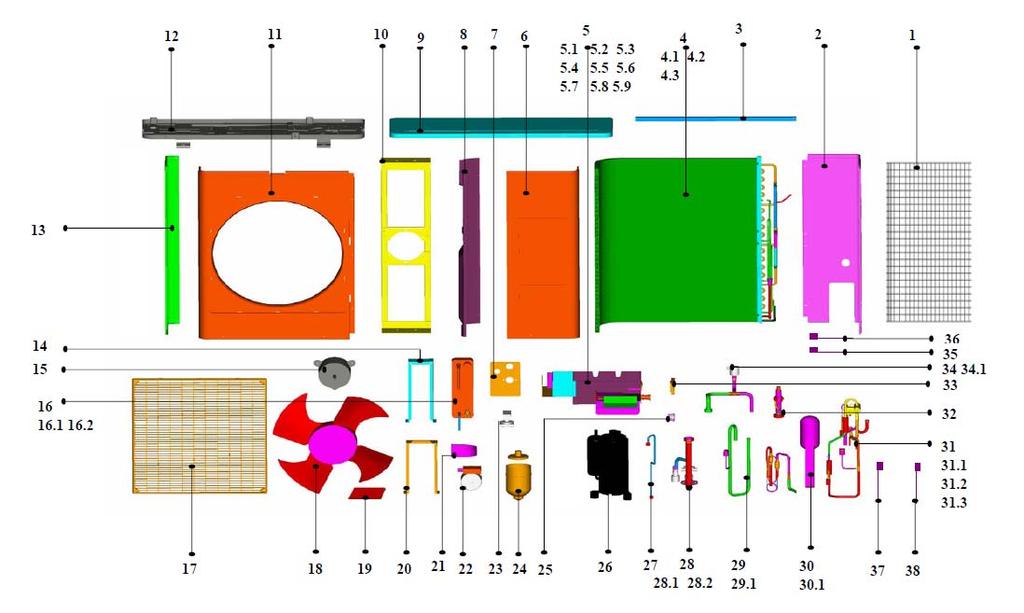
43 MCAC-TSM Outdoor units No. Part Name Quantity No. Part Name Quantity 1 Rear net 1 17 Grille 1 2 Baffle ass'y 1 18 Axial flow fan 1 3 Rear net clap 1 19 Bearing base 1 4 Condenser ass'y 1 20 Heat-exchanger base ass'y Condenser inlet pipe ass'y 1 21 Clamp Condenser outlet pipe ass'y 1 22 Shield pump ass'y Condenser 1 23 Valve Condenser side board 1 24 Expansion vessel 1 5 E-part box ass'y 1 25 Hydraulic meter E-part box 1 26 Compressor Capacitor 1 27 Connecting pipe ass'y Controller 1 28 Connecting pipe ass'y AC contactor Water charge valve Transformer Safety valve Main control board ass'y 1 29 Suction pipe ass'y Urgency switch Pressure controller Filter board ass'y 1 30 Connecting pipe ass'y Compressor capacitor Liquid accumulator can 1 6 Front right clapboard ass'y way valve ass'y 1 7 Water inlet fixing board ass'y way valve 1 8 Partition board ass'y Pressure controller 1 9 Top cover ass'y Solenoid 1 10 Motor bracket ass'y 1 32 Connecting pipe ass'y 1 11 Front panel 1 33 Display cover ass'y 1 12 Base 1 34 Connecting pipe ass'y 1 13 Left holder Discharge valve 1 14 Fixing board ass'y 1 35 Valve electric heater 1 15 Motor 1 36 Temp. sensor ass'y 3 16 Heat-exchanger ass'y 1 37 Discharge temp sensor Heat-exchanger ass'y 1 38 Temp sensor ass'y Heat-exchanger electric heater 1 Outdoor units 41
44 Specification MCAC-TSM MGC-F07W/N1 42 Installation
45 MCAC-TSM Outdoor units No. Part Name Quantity No. Part Name Quantity 1 Rear net 1 17 Grille 1 2 Baffle ass'y 1 18 Axial flow fan 1 3 Rear net clap 1 19 Bearing base 1 4 Condenser ass'y 1 20 Heat-exchanger base ass'y Condenser 1 21 Clamp Condenser inlet pipe ass'y 1 22 Shieled pump ass'y Condenser outlet pipe ass'y 1 23 Valve 1 5 E-part box ass'y 1 24 Expansion vessel E-part box 1 25 Hydraulic meter Capacitor 1 26 Compressor Controller 1 27 Connecting pipe ass'y AC contactor 1 28 Connecting pipe ass'y Transformer Water charge valve Main control board ass'y Safety valve Urgency switch 1 29 Suction pipe ass'y Filter board ass'y Pressure controller Compressor capacitor 1 30 Connecting pipe ass'y 1 6 Front right clapboard ass'y Liquid accumulator can 1 7 Water inlet fixing board ass'y way valve ass'y 1 8 Partition board ass'y way valve 1 9 Top cover ass'y Pressure controller 1 10 Motor bracket ass'y Solenoid 1 11 Front panel 1 32 Inlet pipe ass'y 1 12 Base 1 33 Display cover ass'y 1 13 Left holder 1 34 Connecting pipe ass'y 1 14 Fixing board ass'y Discharge valve 1 15 Motor 1 35 Valve electric heater 1 16 Heat-exchanger ass'y 1 36 Temp.sensor ass'y Heat-exchanger ass'y 1 37 Discharge temp sensor Heat-exchanger electric heater 1 38 Temp sensor ass'y 1 Outdoor units 43

46 Specification MCAC-TSM MGC-F09W/N1 MGC-F10W/N1 44 Installation
47 MCAC-TSM Outdoor units No. Part name Quantity No. Part name Quantity 1 Rear support board II 1 22 Differential pressure valve below joint pipe assembly 2 Condenser 1 23 water-up pipe assy subassembly 1 3 Condenser outlet subassembly 1 24 water-inlet pipe assy subassembly 1 4 Condenser inlet subassembly 1 25 Liquid storage pot connect pipe subassembly 1 5 Expansion vessel 1 26 Plate Heat-exchanger assy assembly 1 6 Accumulator cylinder 1 27 Right fixing board 1 7 Partition plate assembly 1 28 Left fixing board 1 8 Expansive jar clamp 1 29 Holder 1 9 Rear net clip way valve subassembly 1 10 Water Pump way valve Expansion tank joint pipe assembly Electronic control box subassembly Control wire for 4-Ways valve Discharge pipe subassembly Motor capacitor Pressure controller E-part box 1 32 Suction pipe subassembly Power filter plate subassembly Pressure controller Compressor capacitor 1 33 Compressor Compressor capacitor 1 34 Transverse fixing board Transformer 1 35 Show cover subassembly Relay, compressor 1 36 Front panel Contactor 1 37 Chassis Ass'y wave flows out the curb 1 38 Net for air-out frame 2 13 Top cover assembly 1 39 Axial flow fan blade 2 14 Differential pressure valve 1 40 Motor mounting bracket subassembly 1 15 Front clapboard assembly 1 41 Outdoor fan Motor 2 16 Rear clapboard assembly 1 42 Supporting board 1 17 Urgency Switch 1 43 Rear net 1 18 Hydraulic surface 2 44 R410A 3kg 19 Handle 1 45 Temperature sensor subassembly 4 20 Adapter, drain pipe 1 46 Evaporator temp sensor Ⅱ subassembly 1 21 Handle 1 1 Outdoor units 45

48 Specification MCAC-TSM MGC-F10W/SN1 46 Installation
49 MCAC-TSM Outdoor units No. Part Name Quantity No. Part Name Quantity 1 Rear support board II Water charge valve 1 2 Condenser Safety valve 1 3 Fluted pipe ass'y Water-inlet pipe adapter 1 4 Input pipe ass'y 1 25 Connecting pipe ass'y of liquid accumulator 1 5 Expansion vessel Capillary 1 6 Accumulator cylinder Liquid accumulator can 1 7 Partition board ass'y 1 26 Heat-exchanger plate ass'y 1 8 Expansion tank clamp 1 27 Fixing board 1 9 Rear net clip 1 28 Left fixing board 1 10 Drain Pump 1 29 Holder 1 11 Expansion tank joint pipe ass'y way valve ass'y Discharge valve way valve 1 12 E-part box ass'y Ways valve solenoid Motor capacitor 2 31 Discharge pipe ass'y E-part box Pressure controller Filter board ass'y 1 32 Suction pipe ass'y Transformer Pressure controller AC contactor 1 33 Compressor ELIWELL Controller 1 34 Fixing board Power supply control board ass'y 1 35 Display cover ass'y Terminal Front panel Surge suppresser 1 37 Base weldment 1 13 Top cover ass'y 1 38 Grille 2 14 Pressure difference valve 1 39 Axial flow fan 2 15 Front clapboard ass'y 1 40 Motor bracket ass'y 1 16 Rear clapboard ass'y 1 41 Motor 2 17 Urgency switch 1 42 Supporting board 1 18 Hydraulic meter 2 43 Rear net 1 19 Temp. sensor ass'y 1 44 Discharge temp. sensor 1 20 Drain pipe adapter 1 45 Temp. sensor ass'y 3 21 Handle 1 46 Compressor electric heater 1 22 Connecting pipe ass'y 1 47 Pressure difference valve electric heater 1 23 Water pipe ass'y 1 48 Connecting board for condenser 1 24 Water-inlet pipe ass'y 1 Outdoor units 47
50 Specification MCAC-TSM MGC-F12W/SN1 MGC-F16W/SN1 48 Installation
51 MCAC-TSM Outdoor units No. Part Name Quantity No. Part Name Quantity 1 Condenser ass'y Rubber gasket 1 2 Partition board ass'y Electric heating strip 1 3 Expansion vessel Plate Heat-exchanger 1 4 Accumulator cylinder way valve ass'y 1 5 Drain Pump way valve 1 6 Rear net clip Pipe joint 2 7 Expansion tank joint pipe ass'y Ways valve solenoid Discharge valve 1 25 Fixing board Discharge valve joint 1 26 Discharge pipe ass'y Nut Pressure controller 1 8 E-part box ass'y 1 27 Connecting pipe ass'y E-part box Water charge valve Motor capacitor Valve tie-in Transformer Safety valve Power supply control board ass'y Water-inlet pipe adapter Controller Nut Filter board ass'y Pipe joint AC contactor Pipe joint 2 9 Connecting pipe ass'y Rubber gasket Copper nut 2 28 Suction pipe ass'y 1 10 Top cover ass'y Pressure controller 1 11 Water-inlet ass'y 1 29 Compressor Water-inlet ass'y 1 30 Front panel Nut 1 31 Base ass'y Nut 1 32 Grille Pipe joint 1 33 Axial flow fan Pipe joint 1 34 Motor bracket ass'y 1 12 Front right clapboard ass'y 1 35 Motor 2 13 Rear right clapboard ass'y 1 36 Right cover ass'y 1 14 Urgency switch 1 37 Fixing ring 1 15 Hydraulic meter 1 38 Capillary ass'y 1 16 Expansion tank clamp 1 39 Liquid accumulator can ass'y 1 17 Valve Liquid accumulator tank 1 18 Handle 2 40 Rear net 1 19 Drain pipe adapter 1 41 Temp. sensor ass'y 3 20 Display cover ass'y 1 42 Discharge temp sensor 1 21 Plate Heat-exchanger bracket 1 43 Temp. sensor ass'y 1 22 Left fixing board 1 44 Compressor electric heater 1 23 Heat-exchanger plate ass'y 1 45 Valve electric heater Valve tie-in ass'y 1 46 Left clapboard 1 Outdoor units 49

52 Specification MCAC-TSM MGC-F14W/SN1 50 Installation
53 MCAC-TSM Outdoor units No. Part name Quantity No. Part name Quantity 1 Condenser assembly 1 18 Handle 2 2 Middle partition plate subassembly 1 19 Adapter, drain pipe 1 3 Expansion vessel 1 20 Display cover subassembly 1 4 Accumulator cylinder 1 21 Bearing 1 5 Water Pump 1 22 Left fixing board 1 6 Rear net clip 1 23 Plate Heat-exchanger assy assembly 1 7 Expansion tank joint pipe assembly Differential pressure valve tie-in subassembly Discharge valve Rubber gasket Discharge valve joint Electric heater Joint nut Plate Heat-exchanger 1 8 Electronic control box subassembly way valve subassembly E-part box way valve Motor capacitor Pipe joint Surge suppresser Control wire for 4-Ways valve Transformer 1 25 Right fixing board Controller power supply wire 1 26 Discharge pipe subassembly Power supply control board subassembly Pressure controller Controller signal wire 1 27 Water-inlet pipe assembly I Controller subassembly Make-up water valve Power supply blue wire Check valve tie-in Gas protection signal wire Safety valve Liquid protection signal wire Water-inlet pipe tie-in Protection signal wire joint Hex nut Washer for wire joint 1 28 Suction pipe subassembly Remote protection signal wire Pressure controller Signal wire joint 1 29 Compressor 1 Power supply sieve wave board 8.16 subassembly 1 30 Front panel 1 9 Differential pressure valve below joint pipe assembly 1 31 Chassis Ass'y Copper nut 2 32 Net for air-out frame 2 10 Top cover subassembly 1 33 Axial flow fan blade 2 11 Up conjunction pipe subassembly 1 34 Motor mounting bracket subassembly Rubber gasket 2 35 Outdoor fan Motor Transition pipe union 2 36 Right cover subassembly Hex nut 3 37 Fixture, Segregator Hex nut 1 38 Capillary pipe subassembly Copper nut 1 39 liquid accumulator can assembly 1 12 Front right clapboard subassembly liquid accumulator can 1 13 Rear right clapboard subassembly 1 40 Rear net 2 14 Urgency Switch 1 41 Left cover 1 15 Hydraulic surface 1 42 Temperature sensor subassembly 4 16 Expansion can clamp 1 43 Discharge temp sensor 1 17 Differential pressure valve 1 Outdoor units 51
54 Specification 11. Troubleshooting MCAC-TSM Displaying contents Malfunction or protection STY Remote switch in Standby position (automatic reset) Er01 High pressure protection ( manual reset ) Er05 Low pressure protection Er41 3-phase sequence, current and over-heat condenser temperature protection (manual reset) Er30 Frost prevention alarm (manual reset) Er61 Water outlet sensor T02 malfunction (automatic reset) Er62 Coil sensor T03 malfunction (automatic reset) Er60 Water return sensor T01 malfunction (automatic reset) Er20 Water flow protection Er47 Remote keyboard communication error Er45/Er46 Error clock faulty / Error set clock Er90 Alarm history records exceeded 99 times (manual reset) 1. STY Values display indication STY Refer to the instruction manual: Remote switch in Standby position You should set a running mode: cooling or heating, then it will disappear 52 Installation
55 MCAC-TSM Outdoor units 2. Er01 High pressure>4.4mpa, display Er01, compressor and outdoor fan stop, the chiller can only resume from protection manually. Values display indication Er01 Refer to the instruction manual: High pressure protection Judge 1: check the high pressure switch is well. No Replace the high pressure switch Yes Judge 2: Whether the temperature of external and inlet water is high Check the operation conditions: 1. the temperature of inlet water (cooling: below 20, heating: below 45 ) 2. cooling: the indoor temperature is 17 and the ambient temperature is 10 ~43 3. heating: the indoor temperature is 30 and the outdoor temperature is -15 ~24 No Stop the operation, and run it at the normal condition. Yes Judge 3: Whether the refrigerant charge is excessive. Check the temperature of compressor discharge and suction and the pressure of compressor discharge and suction are normal. No Reclaim part of refrigerant Yes Judge 4: Whether the air flow and water flow are insufficient Yes Judge 5: PCB is malfunction. Cooling: Check whether the speed of the fan are normal. Heating: Check whether the water flow volume can reach the data as follow : Capacity ( kw) Water flow volume (m 3 /h) Capacity ( kw) Water flow volume (m 3 /h) No Replace PCB Change the fan or pump. Outdoor units 53
56 Specification MCAC-TSM Low pressure protection (code: Er05) Low pressure<0.15mpa, display Er05, compressor and outdoor fan stop; Low pressure>0.3mpa, compressor and outdoor fan restart (3 minutes delay necessary) If Er05 appears 3 times in 1hour, the chiller can only resume from protection manually. Values display indication Er05 Refer to the instruction manual: Low pressure protection Judge 1: check the low pressure switch is well. Yes No Replace the low pressure switch Judge 2: Whether the temperature of external and inlet water is low Check the operation conditions: 1. the temperature of inlet water (cooling: below 20, heating: below 45 ) 2. cooling: the indoor temperature is 17 and the ambient temperature is 10 ~43 3. heating: the indoor temperature is 30 and the outdoor temperature is -15 ~24 No Stop the operation, and run it at the normal condition. Yes Judge 3: Whether the air is in water circuit. No Yes Recharge the refrigerant Judge 3: Whether the refrigerant charge is abundant. Check the temperature of compressor discharge and suction and the pressure of compressor discharge and suction are normal. No Recharge the refrigerant Yes Judge 5: PCB is malfunction. Replace PCB 54 Installation
57 MCAC-TSM Outdoor units 4. Electric protection Er41: 1) Phase protection of power supply: When the chiller is powered on, if there is wrong sequence of power phase, lack of power phase, it will show Er41, the chiller can not run. 2) Compressor current protection: If the operating current of compressor reaches the value below, system stops and shows Er41: Capacity ( kw) Compressor current value (A) Capacity ( kw) Compressor current value (A) (3N) (1N) Values display indication Er41 Judge 1: Whether the phase sequence of the power line is wrong connected or one phase of the power line is broken off. No Yes Connect the power line well in sequence. Judge 2: Compressor current protection Check whether the compressor current reaches the value in the above table No Judge 3: PCB is malfunction Yes Check whether the refrigerant pipe is air-logged. Yes Dredge the refrigerant pipe. Replace PCB No Check whether the compressor is locked. Yes Replace the compressor. Outdoor units 55
58 Specification MCAC-TSM Error code Er30: Values display indication Er30 Refer to the instruction manual: Frost prevention alarm. Judge 1: Whether the unit has electric, because: When water outlet temperature (T02)<4, water pump and electric heater start working, when water outlet temperature (T02)>6, water pump and electric heater stop working. No Supply the power. Yes Judge 2: Check whether the electric heater is well. No Replace the electric heater Yes Judge 3: Check the water delivery sensor T02 has insert well. No Insert the water delivery sensor T02 well Yes Judge 4: Check the set temperature: cooling= 10 heating = 45 No Reset the point temperature Yes Judge 5: PCB is malfunction Replace the PCB. 56 Installation
59 MCAC-TSM Outdoor units 6. Error code Er61: Values display indication Er61 Refer to the instruction manual: Water delivery sensor T02 malfunction. Judge 1: Whether the sensor falls off. Yes Insert it well. No Judge 2: Check the electrical connection, whether the sensor connects well. No Connects it well. Yes Judge 3: Whether the water delivery sensor T02 malfunction Yes Replace water delivery sensor T02 No Judge 4: PCB is malfunction Yes Replace PCB Outdoor units 57
60 Specification MCAC-TSM Error code Er62: Values display indication Er62 Refer to the instruction manual: Coil sensor T03 malfunction. Judge 1: Whether the sensor falls off. Yes Insert it well. No Judge 2: Check the electrical connection, whether the sensor connects well. No Connect it well. Yes Judge 3: Whether coil sensor T03 is malfunction No Yes Replace coil sensor T03 Judge 4: PCB is malfunction Yes Replace PCB 58 Installation
61 MCAC-TSM Outdoor units 8. Error code Er60: Values display indication Er60 Refer to the instruction manual: Water return sensor T01 malfunction. Judge 1: Whether the sensor falls off. Yes Insert it well. No Judge 2: Check the electrical connection, whether the sensor connects well. No Connects it well. Yes Judge 3: Whether water return sensor T01 is malfunction Yes Replace water return sensor T01 No Judge 4: PCB is malfunction Yes Replace PCB Outdoor units 59
62 Specification MCAC-TSM Error code Er20: Values display indication Er20 Refer to the instruction manual: Water flow protection. Judge 1: Check whether the differential pressure switch is close. No Close the differential pressure switch Yes Judge 2: Check whether the pump is setting high. No Setting the pump in high. Yes Judge 3: Check whether the air is in water circuit, Yes Vent the air No Judge 4: Check whether the filter is air-logged. Yes Clean the impurity. No Judge 5: Check whether the plate heat exchanger is air-logged. Yes Clean the impurity. No Judge 6: PCB is malfunction Replace PCB 60 Installation
63 MCAC-TSM Outdoor units 10. Error code Er47 Values display indication Er47 Refer to the instruction manual: Remote keyboard communication error Judge : Whether the three connecting lines(red, blue and black) are wrong connected. Yes Connect them well in right sequence. 11. Error code Er45/ Er46 Values display indication Er45/ Er46 Refer to the instruction manual: Error clock faulty / Error set clock Set the clock by the controller Outdoor units 61

![recovered by manual reset, please do as follow on the control interface Press [esc + set] in the main screen. The label PAr will appear.](/docs-images/77/76537470/images/64-1.jpg "Scroll with UP and DOWN to find the FnC label. Press set. The label def will appear. Scroll with UP and DOWN to find the EUr label. as the following picture.")
64 Specification MCAC-TSM Error code Er90 Values display indication Er90 Refer to the instruction manual: Alarm history records exceeded 99 times In this condition, it must be recovered by manual reset, please do as follow on the control interface Press [esc + set] in the main screen. The label PAr will appear. Scroll with UP and DOWN to find the FnC label. Press set. The label def will appear. Scroll with UP and DOWN to find the EUr label. as the following picture. Press the set key for 3 seconds [set] The YES = label appears to indicate that the alarm log has been deleted. The trouble is solved. 62 Installation
65 MCAC-TSM Outdoor units Part 3 Installation 1. General Information Description of Standard Unit Installation of Outdoor Unit Hydraulic Connection Electrical Connection Checking and Starting Up the Unit Running and Maintenance...76 Outdoor units 63
66 General Information MCAC-TSM General Information General warning 1. These units have been designed to chill and heat water and must be used in applications compatible with their performance characteristics; these appliances are designed for residential or similar applications. 2. Incorrect installation, regulation and maintenance or improper use absolves the manufacturer from all liability, whether contractual or otherwise, for damage to people, animals or things. Only those applications specifically indicated in this list are permitted. 3. Read this manual carefully. All work must be carried out by qualified personnel in conformity with legislation in force in the country concerned. 4. The guarantee is invalidated if the above instructions are not respected and if the unit is started up for the first time without the presence of personnel authorized by the Company (where specified in the supply contract) who should draw up a start-up report. 5. The documentation supplied with the unit must be consigned to the owner who should keep it carefully for future consultation in the event of maintenance or service. 6. All repair or maintenance work must be carried out by the Company s Technical Service or qualified personnel following the instructions in this manual. The air-conditioner must under no circumstances be modified or tampered with as this may create situations of risk. Failure to observe this condition absolves the manufacturer of all liability for resulting damage. Fundamental safety rules When operating equipment involving the use of electricity and water, a number of fundamental safety rules must be observed, namely: Prohibition 1. This appliance is not intended for use by persons (including children) with reduced physical, sensory or mental capabilities, or lack of experience and knowledge, unless they have been given supervision or instruction concerning use of the appliance by a person responsible for their safety. 2. Do not touch the unit with bare feet or with wet or damp parts of the body 3. Do not carry out cleaning operations without first disconnecting the system from the electricity supply. 4. Do not modify safety or regulation devices without authorization and instructions from the manufacturer. 5. Do not pull, detach or twist the electrical cables coming from the unit, even when disconnected from the mains electricity supply. 6. Do not open doors or panels providing access to the internal parts of the unit without first ensuring that the mains switch is in the off position. 7. Do not introduce pointed objects through the air intake and outlet grills. 8. Do not dispose of, abandon or leave within reach of children packaging materials (cardboard, staples, plastic bags, etc.) as they may represent a hazard. Important 1. The chiller appliances are supplied without the main switch. The power supply to the unit must be disconnected using a suitable main switch that must be supplied and installed by the installer. 2. Respect safety distances between the unit and other equipment or structures. Guarantee adequate space for access to the unit for maintenance and/or service operations; Power supply: the cross section of the electrical cables must be adequate for the power of the unit and the power supply voltage must correspond with the value indicated on the respective units. All units must be earthed in conformity with legislation in force in the country concerned. 3. Hydraulic connections should be carried out as indicated in the instructions to guarantee correct operation of the unit. Empty the water circuit or add glycol if the unit is not used during the winter. Handle the unit with the utmost care to avoid damage. 64 Installation

67 MCAC-TSM Description of Standard Unit 2. Description of Standard Unit These air cooled reverse-cycle chillers with axial-flow fans operate with refrigerant fluid and are suitable for outdoor installation. They are factory tested and on site installation is limited to water and electrical connections. Structure: Panels and base are made from galvanized steel plate painted with epoxy powder to ensure total resistance to atmospheric agents. Condensate collection pan as standard. Compressors: Scroll compressor with crankcase heater and thermal cut-out. Evaporator: AISI 316 stainless steel plate type evaporator complete with electric heater and differential pressure switch. Casing lined with anti-condensate closed cell neoprene cladding. Pump: The units feature a pump with the moving parts in contact with the water made from corrosion resistant materials, extra wear ring on the impeller, built-in capacitor for high starting torque and automatic venting of impeller chamber. Pump assembly: Pump assembly with expansion tank, safety valve, auto water replenishing assembly, pressure gauge and pump. Condensing coil: Made from copper tubes and high surface area aluminum fins. Condensing coil protection grills as standard. Fans: Axial-flow fans. Six-pole electric motor with built-in thermal cut-out. Housed in aerodynamic tubes with accident prevention grill. Device for operation with low outside air temperatures: continuous fan rotation speed control via condensing temperatures transducer. Power and control electrical panel Power and control electrical panel constructed in accordance with IEC 204-1/EN , complete with compressor contactor. Control via HSW7 control panel. Emergency stop push buttons In case system crisis is occur (e. g: Compressor out of control ), press the emergency stop pushbuttons at once, and turn it clockwise, until crisis is removed. Optional accessories: - Removable metal mesh filter. - Remote keyboard kit. - Additional pump. The above accessories are optional. Consult the relative documentation for assembly instructions and technical data. Installation 65
68 Installation of Outdoor Unit 3. Installation of Outdoor Unit MCAC-TSM Choice of installation site Before installing the unit, agree with the customer the site where it will be installed, taking the following points into consideration: - check that the fixing points are adequate to support the weight of the unit; - pay scrupulous respect to safety distances between the unit and other equipment or structures to ensure that air entering the unit and discharged by the fans is free to circulate. 3.2 Positioning Before handling the unit, check the capacity of the lifting equipment used, respecting the instructions on the packaging. To move the unit in the horizontal, make appropriate use of a lift truck or similar, bearing in mind the weight distribution of the unit. To lift the unit, insert tubes long enough to allow positioning of the lifting slings and safety pins in the feet on the unit. To avoid the slings damaging the unit, place protection between the slings and the unit. Position the unit in the site indicated by the customer. Place either a layer of rubber (min. thickness 10 mm) or vibration damper feet (optional) between the base and support surface. Fix the unit, making sure it is level and that there is easy access to hydraulic and electrical components. If the site of installation is exposed to strong winds, fix the unit adequately to the support surface using tie rods if necessary. If a heat pump unit is being installed, make sure the condensate is drained using the drain hose supplied as standard. Prevent leaves, branches or snow from accumulating around the unit. These could reduce the efficiency of the unit. 66 Installation
69 MCAC-TSM Installation of Outdoor Unit 3.3 Service space Dimension A B C D E MGC-F05W/N MGC-F07W/N MGC-F09W/N MGC-F10W/N MGC-F10W/SN MGC-F12W/SN MGC-F14W/SN MGC-F16W/SN Installation 67
70 Hydraulic Connection MCAC-TSM Hydraulic Connection The choice and installation of components is the responsibility of the installer who should follow good working practice and current legislation. Before connecting the pipes, make sure they do not contain stones, sand, rust, dross or other foreign bodies which might damage the unit. Construction of a bypass is recommended to enable the pipes to be washed through without having to disconnect the unit (see drain valves). The connection piping should be supported in such a way as to avoid it weighing on the unit. It is recommended that the following devices are installed in the water circuit of the evaporator: 1. Two pressure gauges with a suitable (inlet and outlet) 2. Two vibration damper joints (inlet and outlet) 3. Two gate valves (normal inlet and calibrating in outlet) 4. A flow switch (inlet) or a differential pressure switch (inlet-outlet). 5. Two thermometers (inlet and outlet). 6. An inlet filter as close as possible to the evaporator and positioned to allow easy access for routine maintenance. 7. An energy-saving water tank. 8. Additional pump. 9. The connecting line of flow switch, which mounted outside the unit, should be connected in series with the pressure-difference No Name No Name No Name 1 Pressure gauge 7 Pump 13 Temperature sensor 2 Vibration damper joint 8 Safety valve 14 Differential pressure switch 3 Gate valve 9 Air vent 15 Drain/chemical washing valve 4 Calibrating valve 10 Expansion tank 16 Plate heat exchanger 5 Flow switch 11 Mesh filter 17 Additional pump 6 Thermometer 12 Auto-water replenishing 18 Additional pump If the installation requires a useful head higher than that obtained by installing a pump assembly and storage tank, it is recommended that an additional pump is installed on the unit. Provided the additional pump installed inside of unit (only model 12/14/16kW can be installed inside of unit), the pump must connected 68 Installation
71 MCAC-TSM Hydraulic Connection close to plate heat exchanger. Provided the pump installed outside of unit, the pump shall be connected at water pipe s outlet. The pump can be easily installed on the unit by removing the pump connection pipe. Important 1) The chillers must be provided with a filling/top-up system connected to the return line and a drain cock in the lowest part of the installation. Installations containing anti-freeze or covered by specific legislation must be fitted with hydraulic disconnections. 2) The manufacturer is not liable for obstruction, breakage or noise resulting from the failure to install filters or vibration dampers. Particular types of water used for filling or topping up must be treated with appropriate treatment systems. For reference values, see the table. PH 6-8 Electrical conductivity Chlorine ions Sulphuric acid ions Total iron Alkalinity M Total hardness Sulphur ions Ammonia ions Silicon ions less than 200 mv/cm (25 C) less than 50 ppm less than 50 ppm less than 50 ppm less than 50 ppm less than 50 ppm none none less than 30 ppm Filling the installation - Before filling, check that the installation drain cock is closed. - Open all installation and terminal air vents. - Open the gate valves. - Begin filling, slowly opening the water filling cock outside the unit - When water begins to leak out of the terminal air vent valves, close them and continue filling until the pressure gauge indicates a pressure of 1.5 bars. Emptying the installation - Before emptying, place the mains switch in the off position - Make sure the installation fill/top-up water cock is closed - Open the drain cock outside the unit and all the installation and terminal air vent valves. Installation 69

 The installation must be filled to a pressure of between 1 and 2 bars. b) It is recommended that this operation be repeated after the unit has been operating for a number of hours.")
72 Hydraulic Connection MCAC-TSM Size and position of connections Model A (mm) B (mm) C (mm) D (mm) E (mm) F (mm) Water inlet/outlet (Ø) Auto-water replenishing (Ø) Security discharge (Ø) MGC-F05W/N R1 G1/2 G1/2 MGC-F07W/N R1 G1/2 G1/2 MGC-F09W/N R5/4 G1/2 G1/2 MGC-F10W/N R5/4 G1/2 G1/2 MGC-F10W/SN R5/4 G1/2 G1/2 MGC-F12W/SN R5/4 G1/2 G1/2 MGC-F14W/SN R5/4 G1/2 G1/2 MGC-F16W/SN R5/4 G1/2 G1/2 Important a) The installation must be filled to a pressure of between 1 and 2 bars. b) It is recommended that this operation be repeated after the unit has been operating for a number of hours. The pressure of the installation should be checked regularly and if it drops below 1 bar, the water content should be topped-up. c) Check the hydraulic tightness of joints. d) If the fluid in the circuit contains anti-freeze, it should not be allowed to drain freely as it is pollutant. e) It should be collected for possible reuse. f) When draining after heat pump operation, take care as the water may be hot (up to 50 ). 70 Installation

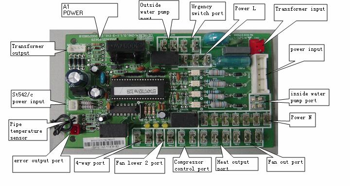
73 MCAC-TSM Electrical Connection 5. Electrical Connection The MGC chillers leave the factory already wired, and require the installation of an omnipolar thermal overload switch, a lockable mains disconnecting switch for the connection to the mains power supply, and the connection of the flow switch to the corresponding terminals. All the above operations must be carried out by qualified personnel in compliance with the legislation in force. For all electrical work, refer to the electrical wiring diagrams in this manual. You are also recommended to check that the characteristics of the mains electricity supply are adequate for the absorptions indicated in the electrical characteristics table below, also bearing in mind the possible use of other equipment at the same time. Important Power to the unit must be turned on only after installation work (hydraulic and electrical) has been completed. All electrical connections must be carried out by qualified personnel in accordance with legislation in force in the country concerned. Respect instructions for connecting phase, neutral and earth conductors. The power line should be fitted upstream with a suitable device to protect against short-circuits and leakage to earth, isolating the installation from other equipment. Voltage must be within a tolerance of ±10% of the rated power supply voltage for the unit (for three phase units, the unbalance between the phases must not exceed 3%).If these parameters are not respected, contact the electricity supply company. For electrical connections, use double insulation cable in conformity with current legislation in the country concerned An omnipolar thermal overload switch and a lockable mains disconnecting switch, in compliance with the CEI-EN standards (contact opening of at least 3mm), with adequate switching and residual current protection capacity based on the electrical data table shown below, must be installed as near as possible to the appliance The devices on the unit must be lockable. An efficient earth connection is obligatory. Failure to earth the appliance absolves the manufacturer of all liability for damage. In the case of three phase units, ensure the phases are connected correctly. Do not use water pipes to earth the unit. Electrical Panel The electrical panel is located inside the unit at the top of the technical compartment where the various components of the refrigerant circuit are also to be found. To access the electrical panel, remove the front panel of the unit by undoing the screws. Installation 71
 phase, (N) neutral and earth in the case of single phase units (220-240V~50Hz), or L1-L2-L3 phases, N neutral and PE earth in three phase")

74 Electrical Connection MCAC-TSM Electrical Panel Layout Electrical Power Connection For the functional connection of the unit, bring the power supply cable to the electrical panel inside the unit and connect it to terminals L-N and respecting the (L) phase, (N) neutral and earth in the case of single phase units ( V~50Hz), or L1-L2-L3 phases, N neutral and PE earth in three phase units (380~415V-3N-50Hz). Auxiliary Connection All terminals referred to in the explanations below are to be found on the terminal board inside the electrical panel and described as installer terminals. Remote start up and shut down To fit a remote on/off device, the jumper must be replaced with a switch connected to terminals 4 and 5 on the installer terminal board. For timed operation, connect a daily or weekly timer between terminals 4 and 5. Remote keyboard kit The remote keyboard kit can be used to display all unit functions and access the parameters of the electronic board from a point located at some distance from the unit itself. 72 Installation
75 MCAC-TSM Electrical Connection It consists of a remote control module. To install the kit, proceed as follows: - disconnect the power supply and then access the inside f the electrical panel; - connect the remote control module with 3 wires to terminals 15, 16 and 17 on the installer terminal board: connect terminal 15 to terminal Black/gnd on the module; connect terminal 16 to terminal Blue/signal on the module; connect terminal 17 to terminal Red/+12v on the module; Important To avoid interference due to magnetic fields, the use of shielded cable is recommended. The cable should not be more than 100m long. The Specification of Power: Type MGC-F05W/N1 MGC-F07W/N1 MGC-F09W/N1 MGC-F10W/N1 Power 220~ ~ ~ ~ Circuit breaker/fuse (A) 25/20 30/25 40/25 40/35 Power wiring (mm 2 ) Ground wiring (mm 2 ) Outdoor /Indoor connecting wiring (mm 2 ) Type MGC-F10W/SN1 MGC-F12W/SN1 MGC-F14W/SN1 MGC-F16W/SN1 Power 380~ ~ ~ ~ Circuit breaker/fuse (A) 25/15 25/15 25/15 30/20 Power wiring (mm 2 ) Ground wiring (mm 2 ) Outdoor /Indoor connecting wiring (mm 2 ) Important The power cord type designation is H07RN-F. Connecting cable between indoor unit and outdoor unit shall be approved poly-chloroprene sheathed flexible cord, type designation H07RN-F or heavier cord. The means for disconnection from a power supply shall be incorporated in the fixed wiring and have an air gap contact separation of at least 3mm in each active(phase) conductors. Installation 73

76 Checking and Starting Up the Unit MCAC-TSM Checking and Starting Up the Unit 6.1 Preparing for first start up Restarting after shutting down for long periods The chiller must be started up for the first time by the Technical Service. Before starting up the chillers, make sure that: - All safety conditions have been respected - The chiller is adequately fixed to the surface it rests on - Functional distances have been respected; - Hydraulic connections have been carried out as indicated in the instruction manual - The water circuit is filled and vented. When draining after heat pump operation, take care as the water may be hot; - The water circuit valves are open - Electrical connections have been carried out correctly - Voltage is within a tolerance of 10% of the rated voltage for the unit - The unit is correctly earthed - All electrical and hydraulic connections are tight and have been completed correctly. Important The unit must be started up for the first time with standard settings. Set point values may be modified only after testing has been completed. Before starting up, power the unit for at least two hours by switching QF1 and QS1 to ON and setting the control panel HSW7 to OFF to allow the oil in the compressor sump to heat up. 6.2 Starting up for the first time (after two hours) Before activating the chiller: - Make sure the main remote switch QF1 is in the OFF position; - Make sure the remote secondary switch SA2 is in the OFF or STANDBY position - Make sure the remote keyboard A6 (if present) is set to OFF To complete the electrical connections: - Remove the inspection panel by unscrewing the five screws 74 Installation
 in the ON position. - The POWER LED on the control panel ST542 comes on to signal that voltage is present. 6.")
77 MCAC-TSM Checking and Starting Up the Unit - Use grommet A for the electrical power cable and grommet B for the other external wires. - Replace the inspection panel. - Position the main switch QF1 (outside the unit) in the ON position. - The POWER LED on the control panel ST542 comes on to signal that voltage is present. 6.3 Activating and deactivating the unit -Set the remote keyboard A6 (if present) to ON. - To ACTIVATE and DEACTIVATE the COOLING and HEATING functions, use the "ST542" control panel or the remote keyboard "A6" if present. During this phase, if the following indications appear on the display, follow the instructions: Important - E20 check water flow rate and differential pressure switch. To access the control panel, open the door: - remove the screw 1 and screw 2; - lift t he door 3. Installation 75
78 Running and Maintenance MCAC-TSM Running and Maintenance 7.1 Operating characteristics Set point in cooling (factory set) = 10 C, Hysteresis = 3 C. The compressor starts with water temperatures above 13 C. The compressor shuts down with water temperatures of less than 10 C. Set point in heating (factory set) = 45 C, Hysteresis = 3 C. The compressor starts with water temperatures below 42 C. The compressor shuts down with water temperatures above 45 C. In the event of a temporary power failure, when power returns, the mode set previously will be retained in the memory. Compressor start up delay Two functions prevent the compressor from starting up too frequently - Minimum time since last shut-down 180 seconds. - Minimum time since last start-up 360 seconds. Pump The electronic board includes a pump control output. The pump starts when the assembly is powered up and at least 120 seconds before the compressor starts up and stops 120 seconds after the assembly shuts down. After the first 120 seconds o f pump operation when the water flow is at full speed, the water flow alarm functions are activated (differential pressure switch and flow switch). With a pump connected to terminals PL and PN on the installer terminal board. Fan speed control For correct operation of the unit with different outside temperatures, the microprocessor controls the fan speed based on the pressure reading from the pressure probe, thus enabling heat exchange to be increased and/or decreased, maintaining the condensing or evaporation temperature practically constant. The fan functions independently of the compressor. Frost prevention alarm To prevent the water freezing and damaging the plate heat exchanger, the microprocessor shuts down the compressor if the temperature measured by the heat exchanger outlet temperature sensor is less than 3 C. The frost prevention temperature set point can be modified by an authorized service centre only and only after verifying that the water circuit contains antifreeze. Tripping of this alarm shuts down the compressor but not the pump, which remains active. To reset normal functions, the outlet water temperature must rise to more than +15 C. Reset is manual. Water flow alarm The microprocessor provides for management of a water flow alarm controlled by a differential pressure switch fitted as standard on the appliance to be installed on the water delivery piping. This safety device may trip after the first 120 seconds of pump operation when the water flow is up to speed. Tripping of this alarm shuts down the compressor but not the pump, which remains active. To reset normal functions, the alarm contact must be deactivated for at least five seconds. When electrical current exceeds to setting value and condenser temperature over than 65 C, system will shut down, but not returns to normal operation until the condenser temperature decreased less than 52 C. If phase sequence were detected error, please re-input power, and then the system will turn normal. 76 Installation
79 MCAC-TSM Running and Maintenance 7.2 Routine maintenance Never perform any cleaning operations before having disconnected the unit from the mains power supply. Regular maintenance is fundamental to maintain the efficiency of the unit both in terms of operation and energy consumption. The Technical Assistance Service maintenance plan must be observed, with an annual service which includes the following operations and checks: - Filling of the water circuit - Presence of air bubbles in the water circuit - Efficiency of safety devices - Power supply voltage - Power input - Tightness of electrical and hydraulic connections - Condition of the compressor contactor - Efficiency of the plate heat exchanger heater - Checking of operating pressure, superheating and sub cooling - Efficiency of compressor heater - Cleaning of finned coil (*) - Cleaning of fan grills - Cleaning of condensate drain pan. (*) For Heat pump appliances, the checks are to be performed quarterly. For units installed near the sea, the intervals between maintenance should be halved. 7.3 Extraordinary maintenance Chemical washing Chemically wash the plate heat exchanger after every 3 years of operation. Refrigerant gas content The chillers are filled with R410a refrigerant gas and tested in the factory. In normal conditions, there should be no need for the Technical Assistance Service to intervene to check the refrigerant gas. However, over time, small leaks may develop at the joints leading to loss of refrigerant and draining of the circuit, causing the unit to function poorly. In this case, the leaks of refrigerant must be identified and repaired and the refrigerant circuit refilled. Proceed as follows: - Empty and dry the entire refrigerant circuit using a vacuum pump connected to the low and high pressure tap until the vacuometer reads about 10Pa. Wait a couple of minutes and check that this value does not rise to more than 200Pa - Connect the refrigerant gas cylinder or a filling cylinder to the low pressure line pressure gauge connection. - Fill with the quantity of refrigerant gas indicated on the rating plate of the unit. - Always check the superheating and sub cooling values. In the nominal operating conditions for the appliance, these should be between 5 and 10 C and between 4 and 8 C respectively. - After a couple of hours of operation, check that the liquid indicator indicates circuit dry (dry-green) Important In the event of partial leaks, the circuit must be completely emptied before being refilled The R410a refrigerant must only be filled in the liquid state. Operating conditions other than nominal conditions may produce considerably different values. Seal testing or identification of leaks must only be carried out using R410a refrigerant gas, checking with a suitable leak detector. Installation 77
80 Running and Maintenance MCAC-TSM Prohibition 1. The refrigerant circuit must not be filled with a refrigerant other than that indicated of specification. 2. The use of a different refrigerant may cause serious damage to the compressor. 3. Oxygen, acetylene or other inflammable or poisonous gases must never be used in the refrigerant circuit as they may cause explosion or poisoning. 7.4 Shutting down for long periods If it is previewed not to use the machine for long periods After deactivating the chiller: - Make sure the remote switch SA 2 is in the "Standby" position, or alternatively disconnect the unit from the power supply. - Make sure the remote keyboard (if present) or the ST542 is set to OFF. - Position QF and QS on OFF - Deactivate the indoor terminal units by placing the switch of each unit in the OFF position. - Close the water valves. Important If there is a possibility that the outside temperature may drop below zero, there is the risk of freezing. The water circuit MUST BE EMPTIED AND SHUT OFF POWER (when draining after heat pump operation take care as the water may be hot) or antifreeze must be added in the proportion recommended by the manufacturer. 78 Installation
81 MCAC-TSM Running and Maintenance Part 4 Controller 1. Standard Controller...80 Installation 79

82 Standard Controller 1. Standard Controller ST542 It is built-in with the chiller at the factory. MCAC-TSM The front panel of the device functions as the user interface and is used to perform all operations relating to the device. 1.1 Introduction of Keys There are 4 keys on the front panel. Each key has: A direct action (indicated on the key). An associated function (indicated on the front panel of the device beside the key). A combined action involving two keys. Keys and associated functions Key Description key Press once (press and release) Key [associated function] Press and hold [press for about 3 seconds] UP (UP) Increases a value Goes to the next label [Manual defrost activation] DOWN (DOWN) Decreases a value Goes to the previous label [Local ON/OFF] Esc(ape) Output (Without saving new settings) Set Confirm (save new settings) Exit without saving new settings Go back to previous level Confirms value/ exit and save new settings Move to next level (open folder, subfolder, parameter, value) Open State Menu disp [Change mode] [Main display] ALL Alarm acknowledgment 1.2 Introduction of Programming menu and State menu Programming menu PAr CF Ui St. Al Parameters FnC def ta St CC EUr Functions See Functions chapter (folder FnC) PASS Password EU Eu States menu From the states menu you can view values for each resource. For some resources, a "dynamic" view is possible. For example, when declared as not present / probe not configured (see System Configuration chapter 80 Controller
83 MCAC-TSM Standard Controller (folder Par/CF), parameter CF01=0), analogue input AI2 will not be displayed. For example the hours of functioning of compressor 2 - CP02 - not available on single compressor machines. Label Visibility Description Change Ai Ai1 Ai2 Ai3 Ai4 // // Dynamic Analogue inputs // di di1 di2 di3 di4 di5 // Dynamic Digital inputs // AO AO1 AO2 AO3 // // // Dynamic Analogue outputs // do do1 do2 do3 do4 do5 do6 Dynamic Digital outputs // CL HOUr date year Clock Yes AL Er Er99 Dynamic Alarms // SP Value // // // // // Set points(set) Yes Sr Value // // // // // Real set point // Hr CP01 CP02 PU01 PU02 // // Dynamic Running time(hours 10) compressor/pumps Yes 1.3 Setting Service Parameters LIST OF ACCESSIBLE PARAMETERS Parameter Description Unit of measure CnF* Machine configuration parameters value CP Compressor parameters value FAn Fan parameters value ALL Alarm parameters value PUP Pump parameters value Fro Frost parameters value dfr Defrost parameters value 1) Local On/OFF Device ON --> OFF Device OFF --> ON Controller 81
84 Standard Controller MCAC-TSM NOTE: The local ON/OFF function is deactivated if the device has been turned OFF remotely or if a digital input is configured as a remote ON/OFF. Remote on/standby and cooling / heating possibilities Remote control of the unit can be done by a voltage free contact. Depending on the setting on the digital controller, the unit will operate in cooling or in heating mode. Procedure a. Connect the cable to the appropriate terminals as shown or the wiring diagram. b. Fix the cable with cable ties to the cable tie mountings to ensure strain relief. NOTE: 1 The remote has priority and controls on/standby operation and change over operation. 2 If you want to use ST542 to control cooling/heating neither the remote, you must to set the parameter CF26 from -14 to 0.Please view parameter (folder PAr). 82 Controller
85 MCAC-TSM Standard Controller 2) Select Operating Mode There are three different operating modes: Standby mode (StbY) Heat mode Cooling mode Instructions are provided below on how to change the operating mode. Controller 83
86 Standard Controller MCAC-TSM ) Select the Clock(CL) 84 Controller
87 MCAC-TSM Standard Controller 4) Modifying a parameter Instructions are provided below on how to change a machine parameter. By way of example, let s look at the CF configuration parameters folder, parameter CF26 (folder PAr/CF/CF26). Controller 85
88 Standard Controller MCAC-TSM ) Set the set point(sp) By way of example, we will change the set point value in COOL mode by 12.0 degrees centigrade to12.5 degrees centigrade. 86 Controller
89 MCAC-TSM Standard Controller Controller 87
 for Pump 2 Press the set key from")


 the running time for compressor 2 (CP02) the")
90 Standard Controller MCAC-TSM ) View and Reset compressor/pump time Example display and reset time (hours x10) for Pump 2 Press the set key from the main display The label Ai will appear on the display. Use the UP and DOWN keys to scroll the other labels until you find the Hr label. Press the set key to view the first label - which in this case is the running time for compressor 1 (CP01) Scroll with the UP and DOWN keys to view (if the relative resources are present) the running time for compressor 2 (CP02) the pump running time (PU01, PU02)/Press the set key to view the pump running time PU Controller


![7) Reset alarm log (folder EUr) Press [esc + set] in the main screen. The label PAr will appear. Scroll with UP and DOWN to find the FnC label.](/docs-images/77/76537470/images/91-2.jpg "Press set. The label def will appear. Scroll with UP and DOWN to find the EUr label.")
![Press the set key for 3 seconds [set] The YES = label appears to indicate that the alarm log has been deleted.](/docs-images/77/76537470/images/91-3.jpg "Keys-combined action Symbol [function associated to the combined pressing of the keys] Combination Keys Combined pressing of keys Press once")
91 MCAC-TSM Standard Controller The tens of hours of functioning are 2. (Hours expressed in tens: 2 means 20 hours of operation). To clear pump running time PU02, press and hold the [set] key. To reset the hours of functioning of pump PU02, press and hold [set]. Note: Repeat the procedure described to reset the hours of functioning of the other resources Press the esc key to go back to the main display. 7) Reset alarm log (folder EUr) Press [esc + set] in the main screen. The label PAr will appear. Scroll with UP and DOWN to find the FnC label. Press set. The label def will appear. Scroll with UP and DOWN to find the EUr label. Press the set key for 3 seconds [set] The YES = label appears to indicate that the alarm log has been deleted. Keys-combined action Symbol [function associated to the combined pressing of the keys] Combination Keys Combined pressing of keys Press once (press and release [associated function] [Menu] / Comments [UP (UP) + DOWN (DOWN)] [Manual reset] See Manual alarm acknowledgment and reset section [Open programming menu] [Esc+SETPOINT] [Programming menu] Controller 89
 An error message will be shown, alternating with the error alert and the main display.")

92 Standard Controller MCAC-TSM ) Manual alarm acknowledgment and reset Alarm messages blink. How to acknowledge an alarm is explained below. All error messages are shown in the AL folder (see state Menu) An error message will be shown, alternating with the error alert and the main display. The ALARM LED will be permanently on. An error can be acknowledged by pressing any key once. After pressing any key, the alarm LED will start to blink. MANUAL RESET To manually reset an alarm, press the up and down keys together [UP+DOWN] N.B: resetting an active alarm* will save the alarm in the AL folder (see state Menu). * i.e. manual reset (alarm) 90 Controller
Part 1 General Information... 1 Part 2 Outdoor Unit... 4 Part 3 Installation... 45
 Contents Part 1 General Information... 1 Part 2 Outdoor Unit... 4 Part 3 Installation... 45 The specifications, designs, and information in this book are subject to change without notice for product improvement.
Content. The specifications, designs, and information in this book are subject to change without notice for product improvement.
 MCAC-ATSM-2014-01 Content R410A Mini Split Chiller 50Hz 1. Model Names of Outdoor Units... 2 2. External Appearance... 2 3. menclature... 3 4. Features... 4 5. Descriptions of Standard Unit... 6 6. Specifications...
Mini unitary chiller. Mini unitary chiller
 Mini unitary chiller Mini unitary chiller Product description Features and benefits Description of main components Specification Operation limits Hydraulic performance Dimension Service space Piping diagram
MINI CHILLER INVERTER H4 Service manual MUENR-H4 (5, 7, 10, 12, 14, 16 kw)
") MINI CHILLER INVERTER H4 Service manual MUENR-H4 (5, 7, 10, 12, 14, 16 kw) CL25610 to CL25615 English Content 1. Outdoor units lineup... 2 2. Nomenclature... 3 3.Features... 4 4. Description of main components...
MINI CHILLER INVERTER H4 Service manual MUENR-H4 (5, 7, 10, 12, 14, 16 kw) CL25610 to CL25615 English Content 1. Outdoor units lineup... 2 2. Nomenclature... 3 3.Features... 4 4. Description of main components...
Aqua Mini Full DC Inverter Unitary Chiller 50Hz. Content
 MCAC-ATSM-2014-09 Content 1. Outdoor units lineup... 2 2. Nomenclature... 3 3.Features... 4 4. Description of main components... 8 5. Specifications... 10 6. Dimensions... 14 7. Piping Diagram... 15 8.
UCV CONDENSING UNITS SPECIFICATIONS 1. Specifications
 UCV CONDENSING UNITS SPECIFICATIONS 1. Specifications Model UCV-76C UCV-96C Code 220075900040 220075900020 Power supply V- Ph-Hz 380-415~3~50 Capacity Btu/h 76000 96000 Cooling Input W 8100 10000 Rated
MANUAL DE INGENIERIA. Part 1 General Information... 1 Part 2 Indoor Units... 6 Part 3 Outdoor Units... 30
 MANUAL DE INGENIERIA Evaporadora Sopladora 'MVA' con Condensadora 'MOV' - Blue Star Part 1 General Information... 1 Part 2 Indoor Units... 6 Part 3 Outdoor Units... 30 Part 1 General Information 1. Model
Part 1 General Information... 1 Part 2 Indoor Units... 7 Part 3 Outdoor Units Part 4 Installation Part 5 Control...
 MCAC-UTSM-2008-11 Contents Part 1 General Information... 1 Part 2 Indoor Units... 7 Part 3 Outdoor Units... 88 Part 4 Installation... 127 Part 5 Control... 136 The specifications, designs, and information
[U] Serie MOV. Manual de Ingeniería
![[U] Serie MOV. Manual de Ingeniería](/thumbs/82/86228730.jpg "[U] Serie MOV. Manual de Ingeniería") [U] Serie MOV Uniidades Condensadoras (Fllujjo Verttiicall) 6..3,, 8 y 12..5 Ton Manual de Ingeniería - 112- Outdoor Units_MOV 1. Specifications.... 2. Dimension... 3. Service Space. 4. Piping Diagrams
[U] Serie MOV Uniidades Condensadoras (Fllujjo Verttiicall) 6..3,, 8 y 12..5 Ton Manual de Ingeniería - 112- Outdoor Units_MOV 1. Specifications.... 2. Dimension... 3. Service Space. 4. Piping Diagrams
Mini Spilt Chiller &Mini Unitary Chiller 50Hz 2012
 MCAC Mini Spilt Chiller &Mini Unitary Chiller Hz Coercial Air Conditioner Business Units Midea Air Conditioning and Refrigeration Sector Add: est region of Midea coercial air conditioner department, Industry
COMMERCIAL AIR CONDITIONERS. Aqua Mini Chiller 50/60Hz
 COMMERCIAL AIR CONDITIONERS Aqua Mini Chiller 50/0Hz Midea CAC (MCAC) As a key subsidiary of Midea Group, the Midea Central Air Conditioner (MCAC) business unit has emerged as a leading supplier of commercial
Midea R410A Tropical ClimaCreator Series Rooftop Package 220V 3Ph 60Hz Technical Manual
 Midea R410A Tropical ClimaCreator Series Rooftop Package 220V 3Ph 60Hz Technical Manual Midea reserves the right to discontinue, or change specification or designs at any time without notices and without
Floor-Standing Type(E Series)
") Floor-Standing Type(E Series) Model: MFE-60CE, MFE-60AE Part 1. Product Features With a spiral shape, the computer-aided simulation designed air passage system can efficiently reduce noise. The Soft touch
Floor-Standing Type(E Series) Model: MFE-60CE, MFE-60AE Part 1. Product Features With a spiral shape, the computer-aided simulation designed air passage system can efficiently reduce noise. The Soft touch
1. Outdoor units lineup
 Content 1. OUTDOOR UNITS LINEUP... 2 2. NOMENCLATURE... 3 3. FEATURES... 4 4. DESCRIPTION OF MAIN COMPONENTS... 7 5. SPECIFICATIONS... 9 6. DIMENSIONS... 13 7. PIPING DIAGRAM... 14 8. WIRING DIAGRAM...
SERVICE MANUAL CONDENSING UNIT ASE-18AH, ASE-24AH, ASE-36AH, ASE-48AH, ASE-60AH
 SERVICE MANUAL CONDENSING UNIT ASE-18AH, ASE-24AH, ASE-36AH, ASE-48AH, ASE-60AH Outdoor Units - appearance 18,000Btu/h 30,000~36,000Btu/h 24,000Btu/h 48,000Btu/h-60,000Btu/h Model Names of Outdoor Units
Product Data. Features/Benefits. 30RQ Air-cooled Modular Chiller R22 & R410A & R407C
 Product Data 30RQ Air-cooled Modular Chiller R22 & R410A & R407C Introduction Air-cooled modular chiller is a kind of central airconditioning unit which adopts air as the cooling (or heating) source and
R22 air-cooled modular chiller 50Hz unit. Content
 Content 1.Nomenclature... 2 2.Product Schedule... 2. External Appearance... 4.Features... 4 5.Specification... 6 6.Dimension... 10 7.Refrigeration System Sketch Drawing... 14 8.Wiring Diagrams... 16 9.Electric
inverter mini chiller
 inverter mini chiller TRUST AIR CONDITIONING EQUIPMENT CO. Prepared By: Engineering & R & D Department. Shiraz- May 2017 Content 1. OUTDOOR UNITS LINEUP... 2 2. FEATURES... 3 3. DESCRIPTION OF MAIN COMPONENTS...
Amendment Sheet. Nomenclature M 5 AC V 100 C R - F X AA. Code : M5ACV Date : Superceded : M5ACV
 Amendment Sheet Code : M5ACV-2005-0002 Date : 08-05-2006 Superceded : M5ACV-2005-0001 Nomenclature Production spec variation Type of ref. connection X : Not applicable Electrical A : 220-240V/1Ph/50Hz
Service manual. MIV V4+ Mini
 DM12-01.01.05en Service manual MIV V4+ Mini DC INVERTER R410A (~220V, 50Hz, 1Ph) MVUH80A-VA1 Contents Part 1 General Information... 1 Part 2 Outdoor Units... 6 Part 3 Installation... 44 DM12-01.01.05en
Content. Part 1 General Information Part 2 Indoor Units Part 3 Outdoor Units Part 4 Installation Part 5 Control...
 R410A Tropical Split Type AC Technical Manual Content Content Part 1 General Information... 2 Part 2 Indoor Units... 6 Part 3 Outdoor Units... 88 Part 4 Installation... 120 Part 5 Control... 154 Indoor
Service Manual. Air Conditional
 Air Conditional Service Manual Большая библиотека технической документации http://splitoff.ru/tehn-doc.html каталоги, инструкции, сервисные мануалы, схемы. -2 - MODEL: AC-FR30CM -3 - CONTENTS SPECIFICATION...
Service Manual. Multi Split Type Heat Pump Air Conditioners. Applied to: HS-9U2IM_HOS-18U2IM HS-9U11IM_HS-12U11IM_HOS-21U11IM
 Service Manual Multi Split Type Heat Pump Air Conditioners Applied to: HS-9U2IM_HOS-18U2IM HS-9U11IM_HS-12U11IM_HOS-21U11IM CONTENT 1. Product features 2. Specification 3. Dimensions 4. Refrigeration cycle
Midea R410A Domestic Pools & Spas Heat Pump Water Heater 50Hz A1 Series Technical Manual
 Midea R410A Domestic Pools & Spas HPWH 50Hz Technical Manual MCAC-HTSM-201409 Midea R410A Domestic Pools & Spas Heat Pump Water Heater 50Hz A1 Series Technical Manual Applicable Model: (New CE safety directive)
Wired controller KJR-08B/BE. Run. Fault. TB Tot. Out. Query. Heat. Net-On. Turn-On Mode
 R0A (kw-0kw) 0Hz KJR-0B/BE is a human-machine interaction(hmi) used for the communication between chiller operator and main board on the chiller itself. The setting and operation order can be send to the
DC Inverter Multi-split System Technical Manual - 50Hz/R410a
 DC Inverter Multi-split System Technical Manual - 50Hz/R410a A/1/LCAC/2/TM/1.0/201111 Content Contents Part 1. General Information... 1 1. Features... 1 2. Nomenclature... 3 3. Products Line-up... 5 4.
Klimaire 16 SEER CENTRAL DUCTED YEAR. Central Air Conditioning & Heat Pump Systems Multi Position Air Handling Units LIMITED GUARANTEE
 Klimaire 16 SEER CENTRAL DUCTED Central Air Conditioning & Heat Pump Systems Multi Position Air Handling Units 10 YEAR LIMITED GUARANTEE R410A R E F R I G E R A N T CSM Condensing Units Features Condensing
MULTIPLO PF Multifunction chillers for indoor installation. Cooling Capacity: kw Heating Capacity: kw
 Multifunction chillers for indoor installation. Cooling Capacity: 22 222 Heating Capacity: 25 236 Scroll compressors EC Plug Fans Plate type heat exchangers EER up to 3,12 COP up to 3,84 ESEER up to 4,01
SMART. 4,9 49,5 kw. Air cooled liquid chillers and heat pumps equipped with scroll compressor and axial fans T_SMT_0609_GB
 T_SMT_0609_GB 4,9 49,5 kw Air cooled liquid chillers and heat pumps equipped with scroll compressor and axial fans INDEX SERIES IDENTIFICATION... 3 MODEL IDENTIFICATION... 3 CE CONFORMITY... 3 WORKING
[U] Serie MHB / MHA Manual de Ingeniería
![[U] Serie MHB / MHA Manual de Ingeniería](/thumbs/86/93369605.jpg "[U] Serie MHB / MHA Manual de Ingeniería") [U] Serie MHB / MHA Evaporadoras Soplladoras de Alltta Presiión Esttáttiica 6..3,, 8 y 12..5 Ton Manual de Ingeniería. - 1 - General Information_MHB 1. Model Names of Indoor/Outdoor Units 2. External Appearance
[U] Serie MHB / MHA Evaporadoras Soplladoras de Alltta Presiión Esttáttiica 6..3,, 8 y 12..5 Ton Manual de Ingeniería. - 1 - General Information_MHB 1. Model Names of Indoor/Outdoor Units 2. External Appearance
SLS 1202 to With or without total heat recovery. u Air Cooled Screw Chillers. 262 to 916 kw. Engineering Data Manual
 u Air Cooled Screw Chillers SLS 1202 to 4004 With or without total heat recovery 262 to 916 kw Engineering Data Manual EDM SLS407-A.4GB Date : December 2008 Supersedes : TM SLS407-A.3GB/11.06 Specifications
1. Product Lineup. 2. External Appearance. 3. Nomenclature M R C 36 H W N1 - R. Power supply R: 380~415V 3Ph~ 50Hz. Refrigerant type N1: R410A
 Contents 1. Product Lineup... 1 2. External Appearance... 1 3. Nomenclature... 1 4. Features... 2 5. List of Functions... 3 6. Specifications... 6 7. Dimensional Drawings... 8 8. Wiring Diagrams... 9 9.
Technical Support Division GD CHIGO HEATING & VENTILATION EQUIPMENT CO., LTD.
 Technical Support Division 2017-4-25 New CMV System - Floor ceiling Indoor Unit 1 1. External appearance 2. Nomenclature 3. Specifications 4. Dimensions 5. Service space 6. Piping diagram 7. Wiring diagram
MODULAR CHILLER. R410a R22
 Ra R 3 Ra/-0 R/-0 New ppearance New Y-shape design, more fashion IR-COOLED SERIES (Ra) Compressor ir cooling side heat exchanger Best scroll compressor, low sound power level, By using calculation model
MHH. 13 SEER High Efficiency R410a. SPECIFICATION sheet
 Air Conditioning and Heating SPECIFICATION sheet MHH 13 SEER High Efficiency R410a Split System Heat Pump Standard features: R410a system High efficiency compressor Compact design for easy installation
CENTRAL AIR CONDITIONERS MINI CHILLER SERVICE MANUAL
 CENTRAL AIR CONDITIONERS MINI CHILLER SERVICE MANUAL T/R40A/50Hz (GC2004) CONTENTS PRODUCT...2 MODELS LIST...2. Split Type...2.2 Integral Type...3 2 NOMENCLATURE...3. Split Type...3.2 Integral Type...4
Ceiling & Floor type Unit
 Ceiling & Floor type Unit Part 1. Product Features Quietest operation, low noise. Thin design, space-saving. Easy to operate, remote control. 16 Part 2. Specification Model MUA-18HRN2 MUA-24HRN2 MUA-24HRN2
R410A50Hz Universal Outdoor Series Technical Manual
 Outdoor Unit R410A 50Hz Universal Outdoor Series Technical Manual 2013 Version LCAC/2.0/201308 I GD Chigo Heating & Ventilation Equipment Co., Ltd. Content Content PART 1.General Information... 1 1.Nomenclature...
Zeta Rev LN HP Prochill Bluebox Print Date: 07/17/2017
 Zeta Rev LN HP 10.2 Configured unit accessories 1PS - One user-side pump with tank LN - Low noise RG - Condensation control with fan speed regulator CSP - Set point compensation depending on external air
Four-way Cassette Type
 Four-way Cassette Type Part 1. Product Features 1) Low operation noise ---Streamline plate ensures quietness ---Creates natural and comfortable environment 2) Efficient cooling ---Equal, fast and wide
Floor-Standing Type(S2 Series)
") Floor-Standing Type(S2 Series) Model: MFS2-24CR(N2), MFS2-24HR(N2), MFS2-24AR(N2), MFS2-48CR(N2), MFS2-48AR(N2) Part 1. Product Features Strong air supply. Wide angle and long distance air supply. Easy
Floor-Standing Type(S2 Series) Model: MFS2-24CR(N2), MFS2-24HR(N2), MFS2-24AR(N2), MFS2-48CR(N2), MFS2-48AR(N2) Part 1. Product Features Strong air supply. Wide angle and long distance air supply. Easy
AIR COOLED FREE-COOLING CHILLERS WITH SCROLL COMPRESSORS AND AXIAL FANS
 RAE 1352 F.K + MV AIR R-407C FC Series RAE... F.K Cooling capacity from 77 to 289 kw - 2 circuits The air cooled chillers of RAE... F.K series, are designed for outdoor installation and are particularly
Midea Precision Air Conditioner Technical Manual (Down delivery series)
") Midea Precision AC Technical Manual-Down Delivery Series MCAC-RTSM-2013-04 Midea Precision Air Conditioner Technical Manual (Down delivery series) Midea reserves the right to discontinue, or change specification
Midea Precision AC Technical Manual-Down Delivery Series MCAC-RTSM-2013-04 Midea Precision Air Conditioner Technical Manual (Down delivery series) Midea reserves the right to discontinue, or change specification
Epsilon Echos kw. General information Air-Water unit with scroll compressors driven by DC inverter. Unique selling points
 Epsilon Echos+ 5 38 kw General information Air-Water unit with scroll compressors driven by DC inverter Configuration /LN: Low noise unit /HP: Reversible heat pump /LE /HP: Reversible condensing unit Unique
Submittal Sheet AIR-CON MULTI-SPLIT II. High-Wall Cassette Duct Floor and Ceiling AMTCM4H4R18
 Submittal Sheet Submitted for: Approval Record Job Name: Contractor: Engineer: Date: Location: Tag: AIR-CON MULTI-SPLIT II Indoor Units Outdoor Unit High-Wall Cassette Duct Floor and Ceiling AMTCM4H4R18
MODEL: CCT 301 INV CCT 501 INV CCT 70 INV-S CCT 100 INV-S CCT 140 INV-S CCT 170 INV-S
 MODEL: CCT 301 INV CCT 501 INV CCT 70 INV-S CCT 100 INV-S CCT 140 INV-S CCT 170 INV-S Compact Four-way Cassette Type 1. Features... 2. Specification... 3. Dimension... 4. Service Space... 5. Wiring Diagram...
30RB Air-Cooled Liquid Chillers. Nominal cooling capacity 8-14 kw. Features. Quiet operation
 Air-Cooled Liquid Chillers www.eurovent-certification.com www.certiflash.com Quality Management Systems 0RB 008-05 Nominal cooling capacity 8- The new generation of Aquasnap liquid chillers was designed
EASY_R R407C. Air cooled liquid chillers and heat pumps equipped with scroll compressor and axial fans. 5,2 41,5 kw T_ESY_R_0508_GB
 R407C EASY_R Air cooled liquid chillers and heat pumps equipped with scroll compressor and axial fans 5,2 41,5 kw T_ESY_R_0508_GB EASY_R R407C INDEX WORKING LIMITS... 3 SERIES IDENTIFICATION... 4 MODEL
CMA TECHNICAL MANUAL CONDENSING UNITS FOR OUTDOOR INSTALLATION O L S A F RA N
 E S A RE F R E IG RA N T G TECHNICAL MANUAL -FRIEND Y CONDENSING UNITS FOR OUTDOOR INSTALLATION O L CMA C 2 The manufacturer declines all the responsabilities regarding inaccuracies contained in this manual,
Air Cooled Scroll Chiller
 Air Cooled Scroll Chiller Midea chillers use H shape heat at air side and single unit s capacity from kw to 0kW. Super chillers are divided to SS,SS-LA, SP-LA and SP-HMLA series according to their water
FALCON Rooftop Units ACPSE 50/60Hz Cooling Capacity : 36 to 1388 MBH (11 to 407 kw) Heating Capacity : 40 to 1298 MBH (12 to 380 kw)
 Heating Capacity : 40 to 1298 MBH (12 to 380 kw)") FALCON Rooftop Units ACPSE 50/60Hz Cooling : 36 to 1388 MBH (11 to 407 ) Heating : 40 to 1298 MBH (12 to 380 ) R Products that perform...by people who care NOMENCLATURE 6 AC P S E 435 P - HP G Q 6-60 Hz
FALCON Rooftop Units ACPSE 50/60Hz Cooling : 36 to 1388 MBH (11 to 407 ) Heating : 40 to 1298 MBH (12 to 380 ) R Products that perform...by people who care NOMENCLATURE 6 AC P S E 435 P - HP G Q 6-60 Hz
Miraco MISR REFRIGERATION & AIR CONDITIONING MFG. CO.
 Miraco MISR REFRIGERATION & AIR CONDITIONING MFG. CO. High Efficiency Green Slim Line Ceiling Concealed Ducted Split Systems Cool Only Rev. August 2015 12K - 18K - 24K - 30K - 36K - 42K - 48K - 60K IAQ
AIR COOLED CHILLERS WITH SCROLL COMPRESSORS AND CENTRIFUGAL FANS
 RAE 201 C K RAE 482 C K AIR R-407C Series RAE... C K from 19 to 83 kw - 1 and 2 circuits The air cooled chillers of RAE... C K series, with centrifugal fans, are designed for indoor installation and are
WATER COOLED HEAT PUMP VERTICAL UNIT CONSOLE TYPE OR RECESSED
 EQV R-407C WATER COOLED HEAT PUMP VERTICAL UNIT CONSOLE TYPE OR RECESSED Size Cooling Heating [kw] [kw] 5 1,9 2,2 7 2,4 2,5 9 2,6 2,5 15 3,3 3,2 17 3,7 3,7 REPLACE: BT02E008GB-01 The Versatemp EQV units
DC Inverter Multi-split System Technical Manual - 50Hz/R410a
 DC Inverter Multi-split System Technical Manual - 50Hz/R410a A/1/LCAC/2/TM/2.0 General Information Contents Part 1. General Information... 4 1. Features... 4 2. Nomenclature... 6 3. Products Line-up...
Air Conditioner Service Manual
 Air Conditioner Service Manual Большая библиотека технической документации http://splitoff.ru/tehn-doc.html каталоги, инструкции, сервисные мануалы, схемы. 2 MODEL: AC-S7HGB 3 CONTENTS TECHNICAL SPECIFICATION..4
1. Features Specification Dimensions Refrigeration cycle diagram Operation limits
 GLORY (ECO) STAR SERIES 1. Features 60 2. Specification 61 61 3. Dimensions 67 67 4. Refrigeration cycle diagram 70 70 5. Operation limits 71 6. Wiring diagram 72 7. Troubleshooting 80 8. Electronic function
AIR COOLED CHILLERS WITH SCROLL COMPRESSORS AND CENTRIFUGAL FANS
 RAE 1402 C O K AIR R-407C Series RAE... C K Cooling capacity from 81 to 250 kw - 2 circuits The air cooled chillers of RAE C K series, with centrifugal fans, are designed for indoor installation and are
GPE Kc UNITS FOR 4-PIPE SYSTEMS WITH SCROLL COMPRESSORS. COOLING CAPACITY FROM 77 TO 426 kw - 2 COOLING CIRCUITS. GPE 802 Kc + CF + GP + MV + P1
 UNITS FOR 4-PIPE SYSTEMS WITH SCROLL COMPRESSORS COOLING CAPACITY FROM 77 TO 426 kw - 2 COOLING CIRCUITS GPE 802 Kc + CF + GP + MV + P1 130 Above picture is only indicative and is not binding. AIR R-410A
500 EX Fusion Compressor Series
 500 EX Fusion Compressor Series R404A M/T R404A L/T Capacity RANGE 13.8kW - 20.4kW 7.7kW -11.2kW Copeland Fusion Semi-Hermetic Horizontal Scroll Compressors For Medium and Low Temperature Applications
UP TO 17.5 SEER / 13.5 EER / 9.5 HSPF HEAT PUMP ENVIRONMENTALLY BALANCED R- 410A REFRIGERANT 2 THRU 5 TONS SPLIT SYSTEM
 EFFICIENT UP TO 17.5 SEER / 13.5 EER / 9.5 HSPF HEAT PUMP ENVIRONMENTALLY BALANCED R- 410A REFRIGERANT 2 THRU 5 TONS SPLIT SYSTEM 208/230 Volt 1- phase REFRIGERATION CIRCUIT S 2- stage scroll compressors
WCH5**4. Product Specifications
 HEAT PUMP HIGH EFFICIENCY 15 SEER 1-1/2 THRU 5 TONS SPLIT SYSTEM ENVIRONMENTALLY BALANCED R- 410A REFRIGERANT 208 / 230 Volt, 1- phase, 60 Hz This product has been designed and manufactured to meet ENERGY
Air-Cooled Condensing Units with Compact Screw Compressors
 LK-SCUTB March 2015 Air-Cooled Condensing Units with Compact Screw s Technical Bulletin Models SSV DSV Table of Contents Nomenclature Chart... 2 Introduction... 3 Bitzer TM s... 4 Magnum TM Microprocessor...
Service Manual. Air Conditional
 Air Conditional Service Manual Большая библиотека технической документации http://splitoff.ru/tehn-doc.html каталоги, инструкции, сервисные мануалы, схемы. -2 - MODEL: AC-FR30HM -3 - CONTENTS SPECIFICATION...
AQH 40 to 130. u Air-to-Water Reverse Cycle Heat Pumps. 40 to 131 kw. 45 to 141 kw. Engineering Data Manual
 u Air-to-Water Reverse Cycle Heat Pumps AQH 40 to 130 40 to 131 kw 45 to 141 kw Engineering Data Manual EDM AQH-W.3GB Date : November 2007 Supersedes : TM AQH-W.2GB/03.04 Specifications The Aqu@Logic air-to-water
NEXT EVO DXR410A NEXT EVO DX NEW SOFTWARE. rcgroupairconditioning
 : Direct expansion close control air conditioners with up-flow or down-flow air delivery. Cooling Capacity: 7 102 NEW SOFTWARE R410A rcgroupairconditioning E C A C UP FLOW DOWN FLOW MAIN FEATURES Precision
CHGV AIR COOLED WATER CHILLER WITH HYDRAULIC EQUIPMENT AIR / WATER 47 to 78 kw
 TECHNICAL INSTRUCTIONS CHGV AIR COOLED WATER CHILLER WITH HYDRAULIC EQUIPMENT AIR / WATER 47 to 78 kw CHGV CHGV 64 CHGV 72 CHGV 80 PHRV heat pump model also available May 2006 10 12 167 - GB - 00 MARKING
R4H4. Product Specifications
 R4H4 Product Specifications EFFICIENT 14 SEER HEAT PUMP ENVIRONMENTALLY BALANCED REFRIGERANT 1-1/2 THRU 5 TONS SPLIT SYSTEM 208 / 230 Volt, 1- phase, 60 Hz REFRIGERATION CIRCUIT S Scroll compressors on
Spare Parts Catalogue MV1006
 Spare Parts Catalogue MV1006 1 - UNIT PANELS - AIR COOLED 2 - UNIT PANELS - WATER COOLED 3 - REFRIGERANT SYSTEM - AIR COOLED - UP TO S.N. 00462 4 - REFRIGERANT SYSTEM - AIR COOLED - FROM S.N. 00463 TO
GLIDER EVO FREE GLIDER EVO FREE GLYCOL FREECOOLING. rcgroupairconditioning
 : Packaged air cooled liquid chillers with free-cooling system for outdoor installation, equipped with screw compressors and axial fans Cooling Capacity: 314 1343 Free-Cooling Capacity: 308 938 GLYCOL
SUBMITTAL M4MCW1509A-SUB-1B. Specifications 15 SERIES. Single Zone Mini-Split Inverter System M4MCW1509A1N0A M4TCS1509A11NA TAG:
 M4MCW1509A-SUB-1B TAG: 15 SERIES SUBMITTAL Specifications Single Zone Mini-Split Inverter System M4MCW1509A1N0A M4TCS1509A11NA MODEL - Cooling Only RATED Volts/PH Frequency (Hz) Rated Cooling Capacity
Multi Inverter Air Conditioning Condensing Units - Summary
 Multi Inverter Air Conditioning Condensing Units - Summary Model Description Nominal Max of Cooling Inverter No. Heating of (kw) Fan Condensing (kw) Coils Unit ECO18MS2 Twin Multi Inverter 5kW 5.2 6.1
SUBMITTAL M4MHW1509A-SUB-1B. Specifications 15 SERIES. Single Zone Mini-Split Inverter System M4MHW1509A1N0A M4THS1509A11NA TAG:
 M4MHW1509A-SUB-1B TAG: 15 SERIES SUBMITTAL Specifications Single Zone Mini-Split Inverter System M4MHW1509A1N0A M4THS1509A11NA 2017 Ingersoll Rand All Rights Reserved MODEL - Heat Pump Only RATED Volts/PH
AIR COOLED CHILLERS FOR OUTDOOR INSTALLATION WITH INTEGRATED FREE COOLING MULTISCROLL SERIES
 AIR COOLED CHILLERS FOR OUTDOOR INSTALLATION WITH INTEGRATED FREE COOLING MULTISCROLL SERIES COOLING CAPACITY FROM 76 TO 612 Kw 1 AND 2 COOLING CIRCUITS RAE 1702 F Kc + P2 28 Above picture is only indicative
WATER CHILLER UNITS AIR COOLED CONDENSER CENTRIFUGAL FANS HEAT PUMP. EWCBZ COOLING ONLY. EWCZ
 WATER CHILLER UNITS AIR COOLED CONDENSER CENTRIFUGAL FANS HEAT PUMP. EWCBZ COOLING ONLY. EWCZ SERIES: EWCBZ - Heat pump MODELS: 70, 80, 00, 0, 60, 00, 40, 00, 50 COOLING CAPACITIES from 5,9 kw to 78,5
Dunham Bush Air Cooled Screw Chiller AFVX B 6SR Series
 Dunham Bush Air Cooled Screw Chiller AFVX B 6SR Series Type of Compressors Compressor Rotary Scroll Reciprocating Screw Centrifugal Air Cooled Chiller 77 ~ 329TR (270 ~ 1156 kw) ACDX Series 100 ~ 520TR
BRT C/H Series PACKAGED AIR TO AIR UNITS COOLING / HEATING APPLICATIONS OUTDOOR INSTALLATION. Ver. 1.01
 b cool manufacturers of air-conditioning equipment ltd BRT C/H Series PACKAGED AIR TO AIR UNITS COOLING / HEATING APPLICATIONS OUTDOOR INSTALLATION Ver. 1.01 Ver. 3.02 01_18 BCool# 1 brt c/h r407c / r410a
MAC N-407 Air-Cooled Chiller
 MAC036-01-N-407 Air-Cooled Chiller Air-Cooled Chillers for Global Residential and Light Commercial MicroClimates MAC036 NOMENCLATURE BREAKDOWN MAC036-01 - N - 407 Refrigerant Type Air-Cooled Chiller 036=
R4H4. Product Specifications
 ENVIRONMENTALLY SOUND REFRIGERANT R4H4 Product Specifications EFFICIENT 14 SEER HEAT PUMP ENVIRONMENTALLY SOUND R 410A REFRIGERANT 1 1/2 THRU 5 TONS SPLIT SYSTEM 208 / 230 Volt, 1 phase, 60 Hz REFRIGERATION
Kälte Klima. Air cooled water chillers air cooled reversible heat pumps from 45 kw to 320 KW. Compressors Scroll SCAEY DE 88 04/11 12/10
 Air cooled water chillers air cooled reversible heat pumps from 45 kw to 320 KW Compressors Scroll Serie: Series: Emissione: Issue: SCAEY Catalogo: Leaflet: Sostituisce: Supersedes: DE 88 04/11 12/10 Index
Service Manual & Installation Manual
 GE Consumer & Industrial Appliances Service Manual & Installation Manual Split System Air Conditioner Model numbers: GE AIR C18 GE AIR C24 GE AIR C34 GE AIR C41 1 Introduction and Features Model Remarks
Air cooled industrial chillers
 Air cooled industrial chillers Main features R410A refrigerant Cooling capacity 5 175 kw Air cooled industrial chillers Models Versions HE High Efficiency Finned coil evaporators submerged in the storage
N4H4. Product Specifications 14 SEER HEAT PUMP. ENVIRONMENTALLY SOUND R 410A REFRIGERANT 1½ THRU 5 TONS SPLIT SYSTEM 208 / 230 Volt, 1 phase, 60 Hz
 ENVIRONMENTALLY SOUND REFRIGERANT N4H4 Performance Series Product Specifications 14 SEER HEAT PUMP ENVIRONMENTALLY SOUND R 410A REFRIGERANT 1½ THRU 5 TONS SPLIT SYSTEM 208 / 230 Volt, 1 phase, 60 Hz REFRIGERATION
Service Manual & Installation Manual
 GE Consumer & Industrial Appliances Service Manual & Installation Manual Split System Air Conditioner Model numbers: GE AIR F24 GE AIR F34 GE AIR F41 1 2 3 Introduction and Features Model Remarks GE AIR
BRAN Residential chillers and heat pumps. Reversible unit, air source for outdoor installation 4,81-27,2 kw <<< BACK INDEX.

Technical Manual. R410A 50Hz Universal Outdoor Series Inverter type. R410A50Hz Universal Outdoor Series Technical Manual LCAC/2016.
 Outdoor Unit R410A 50Hz Universal Outdoor Series Inverter type Technical Manual LCAC/2016.1 I GD Chigo Heating & Ventilation Equipment Co., Ltd. Content Part 1. General Information... 1 1. Nomenclature...
ClimaMaster Series. Rooftop Package Unit 50Hz 1311-R1211. D e a l e r i n f o r m a t i o n
 1311-R1211 GD Midea Refrigeration Equipment Co., Ltd. Is certified under the ISO 9001 International standard for quality assurance. NO.01 100 019209 D e a l e r i n f o r m a t i o n GD Midea Refrigeration
Service Manual. Models WAH418230MB WH418ZMB WAH424230MB WH424ZMB
 Service Manual Models WAH418230MB WH418ZMB WAH424230MB WH424ZMB TABLE OF CONTENT TABLE OF CONTENT... 1 SPECIFICATION... 1 OUTLINE AND INSTALLATION DIMENSION... 3 REFRIGERATION SYSTEM DIAGRAM... 6 WIRING
TECHNICAL & SERVICE MANUAL
 TECHNICAL & SERVICE MANUAL CASSETTE TYPE AIR-CONDITIONER (One-way cassette) FSK-94HF FI-SM-040830 One-way Cassette Air-conditioner Table of Contants Part 1. Product Features 2 Part 2. Specification 3 Part
Air-Cooled Mini Chiller. Models: AMAC 040 A/AR AMAC 050 A/AR AMAC 058 A/AR AMAC 075 B/BR AMAC 100 B/BR AMAC 125 B/BR. Manual No: TMA-AMAC-1161
 Models: AMAC 040 A/AR AMAC 050 A/AR AMAC 058 A/AR AMAC 075 B/BR AMAC 100 B/BR AMAC 125 B/BR Air-Cooled Mini Chiller Manual No: TMA-AMAC-1161 REGISTERED ISO 9002 CONTENTS PAGE 1. NOMENCLATURE SYSTEM...
AQUASNAP JUNIOR 30RHV
 High-Efficiency Air-To-Water Heat Pumps Carrier is participating in the Eurovent Certification Programme. Products are as listed in the Eurovent Directory of Certified Products. AQUASNAP JUNIOR 3RHV 6-11
Air-to-water scroll chillers
 Air-to-water scroll chillers Model CGA 040 to 115 Cooling capacity: 14-40 kw CG-PRC031B-GB Table of Contents Technical specifications...4 Standard configuration... 4 Hydraulic version... 4 Casing... 4
30RB Air-Cooled Liquid Chillers PRODUCT SELECTION DATA. Easy and fast installation. Compact, reliable and efficient
 PRODUCT SELECTION DATA Easy and fast installation Compact, reliable and efficient Class A variable speed circulator available Air-Cooled Liquid Chillers 0RB 008-015 CARRIER participates in the ECP programme
MACH N-407 Heat Pump Air-Cooled Chiller
 MACH060-01-N-407 Heat Pump Air-Cooled Chiller Heat Pump Air-Cooled Chillers for Global Residential and Light Commercial Microclimates MACH NOMENCLATURE BREAKDOWN MACH-060-01 - N - 407 Refrigerant Type
DOLPHIN RADIATOR & COOLING SYSTEMS P.O.Box: 1424,Ph#: , Fax#: ,
 DOLPHIN RADIATOR & COOLING SYSTEMS P.O.Box: 1424,Ph#: +971-6-5432526, Fax#: +971-6-5432415, Email: dolcool@emirates.net.ae, web site: www.dolphinheattransfer.com NOMENCLATURE: INTRODUCTION DOLCOOL branded
NEMO A Split-system liquid chillers for indoor installation. Cooling Capacity: 5 26 kw
 Split-system liquid chillers for indoor installation. Cooling Capacity: 5 26 Built-in pumping group Scroll compressor Plate type heat exchanger EER up to 2,88 rcgroup.it Chillers : Motoevaporating units
Technical Catalogue. Air-Cooled Liquid Chillers with screw compressors Nominal cooling capacity: kw 50 Hz
 EN Technical Catalogue Air-Cooled Liquid Chillers with screw compressors Nominal cooling capacity: 321-1308 kw 50 Hz EKV/BS business Air cooled water chillers for outdoor installation. Flexibility in the
kw. technicalcatalogue
 Packaged air cooled liquid chillers in A class energy efficiency for outdoor installation equipped with scroll compressor and microchannel condensing coils 108 876 kw technicalcatalogue T_PYXCLA_0413_GB
Calor Top 300D(S) Air-source Heat Pump Water Heater
 Air-source Heat Pump Water Heater") v. 13.04 Calor Top 300D(S) Air-source Heat Pump Water Heater INSTALLATION & OWNER S MANUAL Applicable Models: :CALOR TOP 300D CALOR TOP 300D(S) Content 1. General Information... 4 1.1 Measurements... 4
v. 13.04 Calor Top 300D(S) Air-source Heat Pump Water Heater INSTALLATION & OWNER S MANUAL Applicable Models: :CALOR TOP 300D CALOR TOP 300D(S) Content 1. General Information... 4 1.1 Measurements... 4
GLIDER EVO GLIDER EVO. rcgroupairconditioning
 : Packaged air cooled liquid chillers for outdoor installation equipped with screw compressors and axial fans Cooling Capacity: 300 1313 rcgroupairconditioning R134a SHELL C MIN FETURES ir cooled liquid