Part 1 General Information... 1 Part 2 Outdoor Unit... 4 Part 3 Installation... 45
|
|
|
- Elvin Griffin
- 5 years ago
- Views:
Transcription

1 Contents Part 1 General Information... 1 Part 2 Outdoor Unit... 4 Part 3 Installation The specifications, designs, and information in this book are subject to change without notice for product improvement. Contents i
2
3 General Information Part 1 General Information 1. Model Names of Outdoor Units External Appearance menclature Features... 3 General Information 1


4 Model Names of Outdoor Units 1. Model Names of Outdoor Units Model Refrigerant Capacity (kw) Power Supply (V-ph-Hz) MGA-D10/N1 R410A , 1, 50 MGA-D12/N1 R410A , 1, 50 MGA-D14/SN1 R410A , 3, 50 MGA-D16/SN1 R410A , 3, External Appearance 2.1 Outdoor Unit MGA-D10/N1 MGA-D12/N1 MGA-D14/SN1 MGA-D16/SN1 2.2 Water Pump Box 2 General Information
5 3. menclature Outdoor Unit: MGA - D 14 / S N1 menclature Refrigerant N1 R410A Power Supply S: V, 50Hz, 3ph --: V, 50Hz, 1ph Capacity(14kW) D: Digital Scroll Type Midea Chiller 4. Features 1. R410A environment friendly refrigerant. 2. Energy saving and reliable: Adopting Copeland digital scroll compressor, which can adjust the capacity output and satisfy the capacity demands in different working conditions. 3. With remote on-off port and malfunction alarming output port on the main board. 4. Convenient and simple installation: With international popular split design, the pump box can be installed inside the room and its outdoor unit is compact and light. 5. Flexible and convenient control: New wired controller with the Auto-restart functions of adjusting outlet water temperature and power failure memory, etc.. 6. The system doesn t have EMC problem. 7. Built-in with emergency switch: Switch off the unit manually in any emergency case. 8. An AC contactor interface is added on the outdoor unit to connect with the auxiliary electric heater, which can improve the capacity output in heating mode of low temperature. 9. One chiller can connect with more than 1 wired controller, it s convenient to maintain and use. General Information 3
6 Outdoor Unit Part 2 Outdoor Unit 1. Specifications Dimensions Service Space Piping Diagram Wiring Diagrams Electric Characteristics Capacity Tables Operation Limits Hydraulic Performance Sound Levels Exploded View Troubleshooting Outdoor Unit
7 Specifications 1. Specifications Model MGA-D10/N1 MGA-D12/N1 Code Power supply V-Ph-Hz , 1, , 1, 50 Cooling Capacity kw Input W Heating Capacity kw Input W Max. input consumption W Max. input current A Starting current A Model ZPD61KCE-PFZ-532 ZPD61KCE-PFZ-532 Type Digital Scroll Digital Scroll Brand Copeland Copeland Compressor Rated current (RLA) A Locked rotor Amp (LRA) A Thermal protector Inner Inner Capacitor uf 80uF/440V 80uF/440V Refrigerant oil ml POE OIL, 1892 POE OIL, 1892 Model YDK250-6E YDK100-6A( 2) Type AC motor AC motor Outdoor fan motor Brand Welling Welling Input (Hi/Lo) W 307/ /120( 2) Capacitor uf 10uF±5% 450V 5uF/450V Speed (Hi/Lo) r/min 740/ /610 Number of rows 2 2 Tube pitch(a)x row pitch(b) mm Fin spacing mm Fin type Hydrophilic aluminium Hydrophilic aluminium Outdoor coil Φ9.53 Φ9.53 Tube outside dia. and type mm inner grooved tube inner grooved tube Coil length x height x width mm Number of circuits 4 7 Type LDPB2-30(S) LDPB2-30(S) Water pump Input W Pumping head m Rated water flow m 3 /h Max. air flow m 3 /h Throttle Capillary Capillary ise level (sound Outdoor unit db(a) pressure) Water pump box db(a) Minimum water flow m 3 /h The max. and min. water inlet pressure bar 5.0/ /0.5 The volume of expansion tank L 3 3 Dimension (W H D) mm Outdoor unit Packing (W H D) mm Net/ Gross weight kg 109/ /128 Model CE-SBX/N1-01 CE-SBX/N1-01A Code Water pump box Dimension (W H D) mm Packing (W H D) mm Net/ Gross weight kg 52/57 54/59 Refrigerant Type R410A R410A Charged volume g Refrigerant pipe diameter Liquid side mm Φ9.5 Φ9.5 Gas side mm Φ19 Φ19 Pipe diameter Water inlet/outlet mm DN32 DN32 Control Wired controller KJR-08B/BE Ambient temperature Cooling: 10 ~43 Cooling: 10 ~43 Heating: -15 ~24 Heating: -15 ~24 Outdoor Unit 5
8 Specifications Model MGA-D14/SN1 MGA-D16/SN1 Code Power supply V-Ph-Hz , 3, , 3, 50 Cooling Capacity kw Input W Heating Capacity kw Input W Max. input consumption W Max. input current A Starting current A Model ZPD72KCE-TFD-532 ZPD72KCE-TFD-532 Type Digital Scroll Digital Scroll Brand Copeland Copeland Compressor Rated current (RLA) A Locked rotor Amp (LRA) A Thermal protector Inner Inner Capacitor uf / / Refrigerant oil ml 3MAF POE, MAF POE, 1893 Model YDK100-6A( 2) YDK100-6A( 2) Type AC motor AC motor Outdoor fan motor Brand Welling Welling Input (Hi/Lo) W 185/120( 2) 185/120( 2) Capacitor uf 5uF/450V 5uF/450V Speed (Hi/Lo) r/min 860/ /610 Number of rows Tube pitch(a)x row pitch(b) mm Fin spacing mm Fin type Hydrophilic aluminium Hydrophilic aluminium Outdoor coil Φ9.53 Φ9.53 Tube outside dia. and type mm inner grooved tube inner grooved tube Coil length x height x width mm Number of circuits 12 8 Type LDPB2-30(S) LDPB2-30(S) Water pump Input W Pumping head m Rated water flow m 3 /h Max. air flow m 3 /h Throttle Capillary Capillary ise level (sound Outdoor unit db(a) pressure) Water pump box db(a) Minimum water flow m 3 /h The max. and min. water inlet pressure bar 5.0/ /0.5 The volume of expansion tank L 3 3 Dimension (W H D) mm Outdoor unit Packing (W H D) mm Net/ Gross weight kg 123/ /133 Model CE-SBX/SN1-01 CE-SBX/SN1-01A Code Water pump box Dimension (W H D) mm Packing (W H D) mm Net/ Gross weight kg 54/59 55/60 Refrigerant Type R410A R410A Charged volume g Refrigerant pipe diameter Liquid side mm Φ9.5 Φ9.5 Gas side mm Φ19 Φ19 Pipe diameter Water inlet/outlet mm DN32 DN32 Control Wired controller KJR-08B/BE Ambient temperature Cooling: 10 ~43 Cooling: 10 ~43 Heating: -15 ~24 Heating: -15 ~24 6 Outdoor Unit
9 Dimensions 2. Dimensions 2.1 Outdoor Unit Unit: mm Dimensions A B C D E MGA-D10/N MGA-D12/N MGA-D14/SN MGA-D16/SN Water Pump Box Outdoor Unit 7


10 Service Space 3. Service Space 8 Outdoor Unit
11 Piping Diagram 4. Piping Diagram Remark: Name Name Name 1 Compressor 6 Capillary 11 Liquid receiver 2 High pressure switch 7 Liquid receiver 12 Low pressure switch 3 4 -way valve 8 Plate heat exchanger 13 Crank heater 4 Condenser 9 PWM valve 5 Filter 10 Water temperature sensor Outdoor Unit 9
12 Wiring Diagrams 5. Wiring Diagrams 5.1 MGA-D10/N1 10 Outdoor Unit
13 5.2 MGA-D12/N1 Wiring Diagrams 5.3 MGA-D14/SN1 MGA-D16/SN1 Outdoor Unit 11
14 Electric Characteristics 6. Electric Characteristics Mod. kw Electrical Power supply (V-ph-Hz) Rated values Compressors Fan/fans Pump Total Max. values(2) F.L.I. F.L.A. L.R.A. F.L.I. F.L.A. F.L.I. F.L.A. F.L.I. F.L.A. F.L.I. F.L.A. (kw) (A) (A) (kw) (A) (kw) (A) (kw) (A) (kw) (A) A A A A Remark: F.L.I. Power input Fuses Glass 5 20mm 250V Fuse 1 F.L.A. Current input L.R.A. Compressor start-up current (1) Outside air temperature 35 -Water temperature at evaporator 12/7 (2) Values refer to the lower rated voltage(50hz). These values are used to judge the protection switch size and the thickness of the power supply cable. 7. Capacity Tables 7.1 Cooling capacity Model MGA-D10/N1 Ta. ( C) Tw ( C) Pf (kw) Pa (kw) Pat (kw) Qev (m 3 /h) Pev (kpa) Pf (kw) Pa (kw) Pat (kw) Qev (m 3 /h) Pev (kpa) Pf (kw) Pa (kw) Pat (kw) Qev (m 3 /h) Pev (kpa) Pf (kw) Pa (kw) Pat (kw) Qev (m 3 /h) Pev (kpa) Pf (kw) Pa (kw) Pat (kw) Qev (m 3 /h) Pev (kpa) Remark: Ta: outside air temperature ( C) Tw : evaporator water outlet temperature ( C) Pf: cooling capacity (kw) Pa: compressor power input (kw) Pat: total power input (kw) Qev: evaporator water flow (m 3 /h) Pev: evaporator pressure drop (kpa) 12 Outdoor Unit
15 Capacity Tables Model MGA-D12/N1 Ta. ( C) Tw ( C) Pf (kw) Pa (kw) Pat (kw) Qev (m 3 /h) Pev (kpa) Pf (kw) Pa (kw) Pat (kw) Qev (m 3 /h) Pev (kpa) Pf (kw) Pa (kw) Pat (kw) Qev (m 3 /h) Pev (kpa) Pf (kw) Pa (kw) Pat (kw) Qev (m 3 /h) Pev (kpa) Pf (kw) Pa (kw) Pat (kw) Qev (m 3 /h) Pev (kpa) Remark: Ta: outside air temperature ( C ) Tw : evaporator water outlet temperature ( C) Pf: cooling capacity (kw) Pa: compressor power input (kw) Pat: total power input (kw) Qev: evaporator water flow (m 3 /h) Pev: evaporator pressure drop (kpa) Outdoor Unit 13
16 Capacity Tables Model MGA-D14/SN1 Ta. ( C) Tw ( C) Pf (kw) Pa (kw) Pat (kw) Qev (m 3 /h) Pev (kpa) Pf (kw) Pa (kw) Pat (kw) Qev (m 3 /h) Pev (kpa) Pf (kw) Pa (kw) Pat (kw) Qev (m 3 /h) Pev (kpa) Pf (kw) Pa (kw) Pat (kw) Qev (m 3 /h) Pev (kpa) Pf (kw) Pa (kw) Pat (kw) Qev (m 3 /h) Pev (kpa) Remark: Ta: outside air temperature ( C ) Tw : evaporator water outlet temperature ( C) Pf: cooling capacity (kw) Pa: compressor power input (kw) Pat: total power input (kw) Qev: evaporator water flow (m 3 /h) Pev: evaporator pressure drop (kpa) 14 Outdoor Unit
17 Capacity Tables Model MGA-D16/SN1 Ta. ( C) Tw ( C) Pf (kw) Pa (kw) Pat (kw) Qev (m 3 /h) Pev (kpa) Pf (kw) Pa (kw) Pat (kw) Qev (m 3 /h) Pev (kpa) Pf (kw) Pa (kw) Pat (kw) Qev (m 3 /h) Pev (kpa) Pf (kw) Pa (kw) Pat (kw) Qev (m 3 /h) Pev (kpa) Pf (kw) Pa (kw) Pat (kw) Qev (m 3 /h) Pev (kpa) Remark: Ta: outside air temperature ( C ) Tw : evaporator water outlet temperature ( C) Pf: cooling capacity (kw) Pa: compressor power input (kw) Pat: total power input (kw) Qev: evaporator water flow (m 3 /h) Pev: evaporator pressure drop (kpa) Outdoor Unit 15
18 Capacity Tables 7.2 Heating capacity Model MGA-D10/N1 Ta. U.R.87% ( C) Tw ( C) Pt (kw) Pa (kw) Pat (kw) Qc (m 3 /h) Pc (kpa) Pt (kw) Pa (kw) Pat (kw) Qc (m 3 /h) Pc (kpa) Pt (kw) Pa (kw) Pat (kw) Qc (m 3 /h) Pc (kpa) Pt (kw) Pa (kw) Pat (kw) Qc (m 3 /h) Pc (kpa) Pt (kw) Pa (kw) Pat (kw) Qc (m 3 /h) Pc (kpa) Remark: Ta: outside air temperature ( C ) Tw : evaporator water outlet temperature ( C) Pt: heating capacity (kw) Pa: compressor power input (kw) Pat: total power input (kw) Qc: condenser water flow (m 3 /h) ΔPc: evaporator pressure drop (kpa) : conditions outside of operating limits 16 Outdoor Unit
19 Capacity Tables Model MGA-D12/N1 Ta. U.R.87% ( C) Tw ( C) Pt (kw) Pa (kw) Pat (kw) Qc (m 3 /h) Pc (kpa) Pt (kw) Pa (kw) Pat (kw) Qc (m 3 /h) Pc (kpa) Pt (kw) Pa (kw) Pat (kw) Qc (m 3 /h) Pc (kpa) Pt (kw) Pa (kw) Pat (kw) Qc (m 3 /h) Pc (kpa) Pt (kw) Pa (kw) Pat (kw) Qc (m 3 /h) Pc (kpa) Remark: Ta: outside air temperature ( C ) Tw : evaporator water outlet temperature ( C) Pt: heating capacity (kw) Pa: compressor power input (kw) Pat: total power input (kw) Qc: condenser water flow (m 3 /h) ΔPc: evaporator pressure drop (kpa) : conditions outside of operating limits Outdoor Unit 17
20 Capacity Tables Model MGA-D14/SN1 Ta. U.R.87% ( C) Tw ( C) Pt (kw) Pa (kw) Pat (kw) Qc (m 3 /h) Pc (kpa) Pt (kw) Pa (kw) Pat (kw) Qc (m 3 /h) Pc (kpa) Pt (kw) Pa (kw) Pat (kw) Qc (m 3 /h) Pc (kpa) Pt (kw) Pa (kw) Pat (kw) Qc (m 3 /h) Pc (kpa) Pt (kw) Pa (kw) Pat (kw) Qc (m 3 /h) Pc (kpa) Remark: Ta: outside air temperature ( C ) Tw : evaporator water outlet temperature ( C) Pt: heating capacity (kw) Pa: compressor power input (kw) Pat: total power input (kw) Qc: condenser water flow (m 3 /h) ΔPc: evaporator pressure drop (kpa) : conditions outside of operating limits 18 Outdoor Unit
21 Capacity Tables Model MGA-D16/SN1 Ta. U.R.87% ( C) Tw ( C) Pt (kw) Pa (kw) Pat (kw) Qc (m 3 /h) Pc (kpa) Pt (kw) Pa (kw) Pat (kw) Qc (m 3 /h) Pc (kpa) Pt (kw) Pa (kw) Pat (kw) Qc (m 3 /h) Pc (kpa) Pt (kw) Pa (kw) Pat (kw) Qc (m 3 /h) Pc (kpa) Pt (kw) Pa (kw) Pat (kw) Qc (m 3 /h) Pc (kpa) Remark: Ta: outside air temperature ( C ) Tw : evaporator water outlet temperature ( C) Pt: heating capacity (kw) Pa: compressor power input (kw) Pat: total power input (kw) Qc: condenser water flow (m 3 /h) ΔPc: evaporator pressure drop (kpa) : conditions outside of operating limits Outdoor Unit 19
22 Operation Limits 8. Operation Limits Cooling operation Heating operation Outdoor temperature: 10 ~43 Water temperature: 4-20 Outdoor temperature: 4 ~24 (-15 ~24, when charge enough antifreeze) Water temperature: Ethylene Glycol Solutions Water and ethylene glycol solutions used as a thermal vector in the place of water reduce the performance of the unit. Multiply the performance figures by the values given in the following table. Freezing point ( C) Percentage of ethylene glycol in weight 0 12% 20% 28% 35% 40% cpf cq cdp cpf: correction factor refrigerating capacity cq: correction factor flow rate cdp: correction factor pressure drop te: 1. During winter leaving the unit unused, please drain water out completely from unit if no antifreeze were charged into pipeline, or keep power on (at standby or off status) and ensure that water is contained inside of unit. 2. When ambient temperature is lower than 5, running cooling mode must be charged antifreeze. Refer to upper parameters for the charged volume. 8.2 Fouling Factors The performance data given refer to conditions with clean evaporator plates (fouling factor=1). For different fouling factors, multiply the figures in the performance tables by the coefficient given in the following table. Fouling factors Evaporator (m 2 C/W) f1 fk1 fx f1 capacity correction factor fk1 compressor power input correction factor fx1 total power input correction factor 20 Outdoor Unit
23 Hydraulic Performance 8.3 Quantity of Water in Installation Model MGA-D10/N1 MGA-D12/N1 MGA-D14/SN1 MGA-D16/SN1 Minimum water volume (L) If the total water volume in the system is less than the value in the table above, the additional water tank is necessary in order to avoid the compressor On/Off frequency. The minimum size of the water tank is calculated as: Size of additional water tank(l)=minimum water volume (L) Actual water volume(l) 9. Hydraulic Performance 9.1 Pump head curves(*) te: (*) To obtain the useful head of the installation, subtract the pressure drop of the plate heat exchanger. 9.2 Heat exchanger pressure drop (water side) Model 10kW Water flow m 3 / h l/sec Pressure drop kpa Model Water flow m 3 / h l/sec kw kpa kw Pressure drop kpa kw kpa Outdoor Unit 21
24 Sound Levels 10. Sound Levels 10kW 12/14/16kW Microphone H 1.0m te: H= 0.5 height of outdoor unit te: The point A is in the middle of the whole outdoor panel. Model ise level db(a) MGA-D10/N1 57 MGA-D12/N1 60 MGA-D14/SN1 60 MGA-D16/SN Outdoor Unit

25 Exploded View 11. Exploded View 11.1 MGA-D10/N1 Matched water pump box- CE-SBX/N1-01 Outdoor Unit 23
26 Exploded View MGA-D10/N1. Part Name Quantity. Part Name Quantity 1 Top cover ass'y Wire joint 1 2 Rear Supporter Compressor capacitor 1 3 Condenser ass'y Wire clamp 1 4 High pressure valve ass'y 1 8 Separator Low pressure valve 1 9 Big handle 1 5 Partition board ass'y 1 10 Front right clapboard ass'y 1 6 Rear right clapboard ass'y 1 11 Valve plate 1 7 E-part box ass'y 1 12 Compressor communication wire 1 13 Branch pipe ass'y Transformer 1 14 Compressor electric heater Cable 1 15 Base ass'y Damp 1 16 Suction pipe ass'y Electric installation board Pressure controller Capacitor 1 17 Solenoid valve ass'y Capacitor installation board Pressure-relief-valve Capacitor clamp way valve ass'y Capacitor clamp Solenoid Wire clamp way valve Terminal board Low pressure valve Urgency switch Pressure controller AC contactor 1 19 Axial flow fan Wire joint ass'y 1 20 Motor Wire joint 1 21 Motor bracket ass'y Wire joint 1 22 Grille Wire joint 3 23 Front panel Wire joint 1 24 Wire controller Wire joint 1 25 Left holder Surge suppresser 1 26 Temp sensor Caution label 1 27 Pipe temp sensor ass'y Power supply wire 1 28 Discharge temp sensor ass'y Main control board ass'y 1 29 Discharge temp sensor Outdoor communication cable 1 Water pump box CE-SBX/N1-01. Part Name Quantity. Part Name Quantity 1 Up covering plate Branch pipe 2 2 Water-inlet pipe ass'y Screw Pipe joint Elbow pipe Elbow pipe Inner joint 1 3 Hook 4 19 Water charge valve 1 4 Pipe clamp I 1 20 Rear clapboard 2 5 Front clapboard 1 21 Input pipe ass'y 1 6 Pipe clamp II Pipe joint 1 7 Right cover ass'y Copper nut 1 8 Capacitor clamp 1 22 Water-outlet pipe ass'y 1 9 Water-inlet pipe supporter Water-outlet pipe ass'y I 1 10 Input pipe ass'y Drain pipe adapter Accumulator tank 1 23 Water-outlet pipe ass'y II 1 11 Water-inlet pipe ass'y Elbow pipe outer joint Water-outlet pipe II Pipe joint Pipe joint Water-inlet pipe ass'y I 1 24 Pump 1 12 Base 1 25 Water-outlet pipe ass'y I 1 13 Expansion vessel Pipe joint 3 14 Heat-exchanger plate ass'y Elbow pipe Plate Heat-exchanger 1 26 Installation bracket Elbow pipe 1 27 Big handle Pipe joint 1 28 Left clapboard ass'y Pipe hoop 1 29 Safety valve Pipe joint 1 30 Discharge valve Copper nut 1 31 Water-outlet pipe III 1 15 Target flow-volume controller 1 32 Input pipe ass'y 1 16 Clamp Accumulator tank 1 17 Water charge pipe 1 33 Temp. sensor ass'y 1 18 Water-inlet pipe ass'y II 1 34 Wire joint, 5p Pipe joint 3 24 Outdoor Unit

27 Exploded View 11.2 MGA-D12/N1 Matched water pump box- CE-SBX/N1-01A Outdoor Unit 25
28 Exploded View MGA-D12/N1. Part Name Quantity. Part Name Quantity 1 Top cover ass'y way valve ass'y 1 2 Accumulator cylinder way valve 1 3 Condenser ass'y Ways valve solenoid 1 4 Valve plate Low pressure valve 1 5 Front clapboard ass'y 1 12 Compressor 1 6 E-part box ass'y 1 13 Base AC contactor 1 14 Compressor electric heater Surge suppresser 1 15 Discharge pipe ass'y Capacitor clamp Pressure controller Compressor capacitor 1 16 Suction pipe ass'y Main control board ass'y Pressure controller Transformer Pressure-relief-valve Wire joint 1 17 Partition board ass'y Motor capacitor 2 18 Grille Wire joint, 3p 1 19 Motor Wire joint 1 20 Wire controller Electric installation board ass'y 1 21 Axial flow fan Cable 1 22 Motor bracket ass'y Power supply wire 1 23 Rear support board I Wire joint 3 24 Rear net clip Wire joint 1 25 Front panel Wire joint 1 26 Discharge temp sensor ass'y 1 7 Urgency switch 1 27 Temp sensor ass'y 1 8 Rear clapboard ass'y 1 28 Room temp sensor ass'y 1 9 Handle 2 29 Discharge temp sensor 1 10 High pressure valve ass'y 1 30 Fixing ring Low pressure valve 1 31 Rear support board II 1 Water pump box CE-SBX/N1-01A. Part Name Quantity. Part Name Quantity 1 Up covering plate Branch pipe 2 2 Water-inlet pipe ass'y Screw Pipe joint Elbow pipe Elbow pipe Inner joint 1 3 Hook 4 19 Water charge valve 1 4 Pipe clamp I 1 20 Rear clapboard 2 5 Front clapboard 1 21 Input pipe ass'y 1 6 Pipe clamp II Pipe joint 1 7 Right cover ass'y Copper nut 1 8 Capacitor clamp 1 22 Water-outlet pipe ass'y 1 9 Water-inlet pipe supporter Water-outlet pipe ass'y I 1 10 Input pipe ass'y Drain pipe adapter Accumulator tank 1 23 Water-outlet pipe ass'y II 1 11 Water-inlet pipe ass'y Elbow pipe outer joint Water-outlet pipe II Pipe joint Pipe joint Water-inlet pipe ass'y I 1 24 Pump 1 12 Base 1 25 Water-outlet pipe ass'y I 1 13 Expansion vessel Pipe joint 3 14 Heat-exchanger plate ass'y Elbow pipe Plate Heat-exchanger 1 26 Installation bracket Elbow pipe 1 27 Big handle Pipe joint 1 28 Left clapboard ass'y Pipe hoop 1 29 Safety valve Pipe joint 1 30 Discharge valve Copper nut 1 31 Water-outlet pipe III 1 15 Target flow-volume controller 1 32 Input pipe ass'y 1 16 Clamp Accumulator tank 1 17 Water charge pipe 1 33 Temp. sensor ass'y 1 18 Water-inlet pipe ass'y II 1 34 Wire joint, 5p Pipe joint 3 26 Outdoor Unit


29 11.3 MGA-D14/SN1 Exploded View Matched water pump box- CE-SBX/SN1-01 Outdoor Unit 27
30 Exploded View MGA-D14/SN1. Part Name Quantity. Part Name Quantity 1 Top cover ass'y way valve 1 2 Accumulator cylinder Ways valve solenoid 1 3 Condenser ass'y Low pressure valve 1 4 Valve plate 1 12 Compressor 1 5 Front clapboard ass'y 1 13 Base 1 6 E-part box ass'y 1 14 Compressor electric heater AC contactor 1 15 Discharge pipe ass'y Surge suppresser Pressure controller Main control board ass'y 1 16 Suction pipe ass'y Transformer Pressure controller Wire joint Pressure-relief-valve Motor capacitor 2 17 Motor bracket ass'y Wire joint, 3p 1 18 Grille Wire joint 1 19 Motor Electric installation board ass'y 1 20 Wire controller Cable 1 21 Axial flow fan Outdoor communication cable 1 22 Motor bracket ass'y Wire joint 3 23 Rear support board I Wire joint 1 24 Rear net clip Wire joint, 5p 1 25 Front panel 1 7 Urgency switch 1 26 Discharge temp sensor ass'y 1 8 Rear clapboard ass'y 1 27 Temp sensor ass'y 1 9 Handle 2 28 Discharge temp sensor 1 10 High pressure valve ass'y 1 29 Room temp sensor ass'y Low pressure valve 1 30 Fixing ring way valve ass'y 1 31 Rear support board II 1 Water pump box CE-SBX/SN1-01. Part Name Quantity. Part Name Quantity 1 Up covering plate Branch pipe 2 2 Water-inlet pipe ass'y Screw Pipe joint Elbow pipe Elbow pipe Inner joint 1 3 Hook 4 19 Water charge valve 1 4 Pipe clamp I 1 20 Rear clapboard 2 5 Front clapboard 1 21 Input pipe ass'y 1 6 Pipe clamp II Pipe joint 1 7 Right cover ass'y Copper nut 1 8 Capacitor clamp 1 22 Water-outlet pipe ass'y 1 9 Water-inlet pipe supporter Water-outlet pipe ass'y I 1 10 Input pipe ass'y Drain pipe adapter Accumulator tank 1 23 Water-outlet pipe ass'y II 1 11 Water-inlet pipe ass'y Elbow pipe outer joint Water-outlet pipe II Pipe joint Pipe joint Water-inlet pipe ass'y I 1 24 Pump 1 12 Base 1 25 Water-outlet pipe ass'y I 1 13 Expansion vessel Pipe joint 3 14 Heat-exchanger plate ass'y Elbow pipe Plate Heat-exchanger 1 26 Installation bracket Elbow pipe 1 27 Big handle Pipe joint 1 28 Left clapboard ass'y Pipe hoop 1 29 Safety valve Pipe joint 1 30 Discharge valve Copper nut 1 31 Water-outlet pipe III 1 15 Target flow-volume controller 1 32 Input pipe ass'y 1 16 Clamp Accumulator tank 1 17 Water charge pipe 1 33 Temp. sensor ass'y 1 18 Water-inlet pipe ass'y II 1 34 Wire joint, 5p Pipe joint 3 28 Outdoor Unit
31 Exploded View 11.4 MGA-D16/SN1 Matched water pump box- CE-SBX/SN1-01A Outdoor Unit 29
32 Exploded View. Part Name Quantity. Part Name Quantity 1 Top cover ass'y way valve 1 2 Accumulator cylinder Ways valve solenoid 1 3 Condenser ass'y Low pressure valve 1 4 Valve plate 1 12 Compressor 1 5 Front clapboard ass'y 1 13 Base 1 6 E-part box ass'y 1 14 Compressor electric heater AC contactor 1 15 Discharge pipe ass'y Surge suppresser Pressure controller Main control board ass'y 1 16 Suction pipe ass'y Transformer Pressure controller Wire joint Pressure-relief-valve Motor capacitor 2 17 Motor bracket ass'y Wire joint, 3p 1 18 Grille Wire joint 1 19 Motor Electric installation board ass'y 1 20 Wire controller Cable 1 21 Axial flow fan Outdoor communication cable 1 22 Motor bracket ass'y Wire joint 3 23 Rear support board I Wire joint 1 24 Rear net clip Wire joint, 5p 1 25 Front panel 1 7 Urgency switch 1 26 Discharge temp sensor ass'y 1 8 Rear clapboard ass'y 1 27 Temp sensor ass'y 1 9 Handle 2 28 Discharge temp sensor 1 10 High pressure valve ass'y 1 29 Room temp sensor ass'y Low pressure valve 1 30 Fixing ring way valve ass'y 1 31 Rear support board II 1 Water pump box CE-SBX/SN1-01A. Part Name Quantity. Part Name Quantity 1 Up covering plate Branch pipe 2 2 Water-inlet pipe ass'y Screw Pipe joint Elbow pipe Elbow pipe Inner joint 1 3 Hook 4 19 Water charge valve 1 4 Pipe clamp I 1 20 Rear clapboard 2 5 Front clapboard 1 21 Input pipe ass'y 1 6 Pipe clamp II Pipe joint 1 7 Right cover ass'y Copper nut 1 8 Capacitor clamp 1 22 Water-outlet pipe ass'y 1 9 Water-inlet pipe supporter Water-outlet pipe ass'y I 1 10 Input pipe ass'y Drain pipe adapter Accumulator tank 1 23 Water-outlet pipe ass'y II 1 11 Water-inlet pipe ass'y Elbow pipe outer joint Water-outlet pipe II Pipe joint Pipe joint Water-inlet pipe ass'y I 1 24 Pump 1 12 Base 1 25 Water-outlet pipe ass'y I 1 13 Expansion vessel Pipe joint 3 14 Heat-exchanger plate ass'y Elbow pipe Plate Heat-exchanger 1 26 Installation bracket Elbow pipe 1 27 Big handle Pipe joint 1 28 Left clapboard ass'y Pipe hoop 1 29 Safety valve Pipe joint 1 30 Discharge valve Copper nut 1 31 Water-outlet pipe III 1 15 Target flow-volume controller 1 32 Input pipe ass'y 1 16 Clamp Accumulator tank 1 17 Water charge pipe 1 33 Temp. sensor ass'y 1 18 Water-inlet pipe ass'y II 1 34 Wire joint, 5p Pipe joint 3 30 Outdoor Unit
33 Troubleshooting 12. Troubleshooting 12.1 Troubles Cause and Solution Troubles Causes Solution 1. Voltage is out of operation Check wiring and circuit range. Water pump doesn t work 2. Water flow in the water pump Check whether the water system is blocked with box is abnormal sundries. Clean the filter and refill water. 1. Open-circuit of compressor Water pump works while connector Check the cable connection. compressor not 2. Open-circuit of compressor wiring Check the cable connection. 1. Improper adjustment to water Temp. of chilled or hot water Adjust the water valve. valve abnormal 2. Overload Change to a bigger capacity chiller. Compressor can t run automatically after stop 1. Heating in summer Change the mode into cooling mode. 2. Cooling in winter Change the mode into heating mode Malfunction Code Code Malfunction Code Malfunction E0 Water flow test malfunction P0 Current protection E1 Phase sequence malfunction P1 High pressure protection E2 In-outdoor unit communication checking channel is abnormal P2 Low pressure protection E3 Backwater temperature sensor checking channel is abnormal P3 Discharge air temperature protection E4 Outdoor environment temperature sensor checking channel is abnormal P4 Inlet outlet water temperature difference protection E5 Outlet water temperature sensor checking channel is abnormal P5 Condenser high temperature protection E6 Condenser temperature sensor checking channel is abnormal P6 Plate heat exchanger low temperature protection E7 Plate heat exchanger temperature sensor 1 checking channel is abnormal Pb System anti-frozen protection E8 E9 Plate heat exchanger temperature sensor 2 checking channel is abnormal Digital scroll compressor discharge temperature sensor is abnormal (thermostat display E4) P8 Inlet temperature protection (three times in one hour and system should be powered on again) At this time, the wired controller displays P4 Outdoor Unit 31
34 Troubleshooting E0: Water flow test malfunction LED indicates E0 Judge 1: The water pump gets faulty. Check the water pump, and repair or replace it if necessary. Judge 2: Water flow switch gets faulty. Check the water flow switch, and repair or replace it if necessary. Judge 3: Check whether the water system is blocked. The _ T inlet water T outlet water _ >10 Check the water system and clean the filter. Judge 4: There is air left in the water system. Exhaust the air. Judge 5: Check whether the circulation water is insufficient Check the water system and make adjustment. 32 Outdoor Unit
35 Troubleshooting E1: Phase sequence malfunction LED indicates E1 Judge 1: Check whether the phase order of 3-phase power supply is incorrect Swap the power lines of any two phases. Judge 2: Check whether the 3-phase power supply is lack of phase Check the power supply and power cable E2: In-outdoor unit communication checking channel is abnormal LED indicates E2 Judge 1: Check whether the signal wires of P, Q, (E) are wrong connected. Connect them well Judge 2: Check whether the wired controller and outdoor unit are all powered on Put on the power Replace the PCB Outdoor Unit 33
36 Troubleshooting E3: Backwater temperature sensor checking channel is abnormal LED indicates E3 Judge 1: Check whether the wiring of backwater temperature sensor is break off Connect the wiring well Judge 2: Check whether the backwater temperature sensor is broken: see whether the resistance of backwater temperature sensor is wrong refer to the Annex 1 Replace the backwater temperature sensor Replace the PCB E4: Outdoor environment temperature sensor checking channel is abnormal LED indicates E4 Judge 1: Check whether the wiring of outdoor environment temperature sensor is break off Connect the wiring well Judge 2: Check whether the outdoor environment temperature sensor is broken: see whether the resistance of outdoor environment temperature sensor is wrong refer to the Annex 1 Replace the outdoor environment temperature sensor Replace the PCB 34 Outdoor Unit
37 E5: Outlet water temperature sensor checking channel is abnormal Troubleshooting LED indicates E5 Judge 1: Check whether the wiring of outlet water temperature sensor is break off Connect the wiring well Judge 2: Check whether the outlet water temperature sensor is broken: see whether the resistance of outlet water temperature sensor is wrong refer to the Annex 1 Replace the outlet water temperature sensor Replace the PCB E6: Condenser temperature sensor checking channel is abnormal LED indicates E6 Judge 1: Check whether the wiring of condenser temperature sensor is break off Connect the wiring well Judge 2: Check whether the condenser temperature sensor is broken: see whether the resistance of condenser temperature sensor is wrong refer to the Annex 1 Replace the condenser temperature sensor Replace the PCB Outdoor Unit 35
38 Troubleshooting E7: Plate heat exchanger temperature sensor 1 checking channel is abnormal LED indicates E7 Judge 1: Check whether the wiring of plate heat exchanger temperature sensor 1 is break off Connect the wiring well Judge 2: Check whether the plate heat exchanger temperature sensor 1 is broken: see whether the resistance of plate heat exchanger temperature sensor is wrong refer to the Annex 1 Replace the plate heat exchanger temperature sensor 1 Replace the PCB E8: Plate heat exchanger temperature sensor 2 checking channel is abnormal LED indicates E8 Judge 1: Check whether the wiring of plate heat exchanger temperature sensor 2 is break off Connect the wiring well Judge 2: Check whether the plate heat exchanger temperature sensor 2 is broken: see whether the resistance of plate heat exchanger temperature sensor is wrong refer to the Annex 1 Replace the plate heat exchanger temperature sensor 2 Replace the PCB 36 Outdoor Unit
39 E9: Digital scroll compressor discharge temperature sensor is abnormal (thermostat display E4) Troubleshooting LED indicates E9 Judge 1: Check whether air outlet is blocked by sundries. Clear the sundries to ensure smooth air exhaust. Judge 2: Check whether the condenser coil fin gets dirty Clean the condenser. Judge 3: Check whether the ambient temperature is too high. Add sunshade facilities. Judge 4: Check whether the condenser fan is abnormal Check the outdoor fan. Judge 5: Check whether the refrigerant is charged too little Recharge the refrigerant Outdoor Unit 37
40 Troubleshooting P0: Current protection LED indicates P0 Judge 1: Check whether the compressor motor gets faulty. Check the compressor, and repair or replace it if necessary. Judge 2: Check whether the refrigerant is charged too much (the high pressure> 3.8MPa) Reduce the refrigerant Judge 3: Check whether air outlet is blocked by sundries. Clear the sundries to ensure smooth air exhaust. Judge 4: Check whether the condenser coil fin gets dirty Clean the condenser. Judge 5: Check whether the ambient temperature is too high. Add sunshade facilities. Judge 6: Check whether the condenser fan is abnormal Check the outdoor fan. Judge 7: Check whether the power voltage is too low, For 1 phase unit: power voltage <198V; for 3 phase unit: <342V Check and repair the power supply. 38 Outdoor Unit
41 P1: High pressure protection Troubleshooting LED indicates P1 High pressure protection Judge 1: Whether the wiring between the high pressure switch and main control board is connected well and correctly Judge 2: Whether the high pressure switch is broken Connect it well Validate: Short connect the high pressure switch socket, check whether the system can run normally Replace high pressure switch Judge 3: Whether the air exhaust temperature controller gets faulty Check whether the refrigerant system is ok Replace air exhaust temperature controller Judge 4: Check whether the outdoor ambient temperature is too high Judge 5: Check whether the outdoor unit is bad ventilation Judge 6: Check whether the heat exchanger is dirty Stop the unit Make the outdoor unit ventilate well Clean the heat exchanger Judge 6: Check whether the refrigerant pipe is blocked Drop refrigerant, then use the high pressure nitrogen or refrigerant to blow pipe, vacuumize and add the refrigerant again Replace outdoor main board Outdoor Unit 39
42 Troubleshooting P2: Low pressure protection LED indicates P2 Low pressure protection Judge 1: The wiring between the low pressure switch and main control board is connected well or correctly Connect it well Judge 2: Whether the low pressure switch is broken Validate: Short connect the low pressure switch socket, check whether the system can run normally Replace low pressure switch Check whether the refrigerant system is ok Judge 3: Check whether the outdoor ambient temperature is too low Judge 4: The refrigerant of the system is leakage Validate: Connect the pressure gauge to the gauge joint of the system, check whether the pressure is lower than 0.15MPa Judge 5: The refrigerant pipe is blocked Leak hunting: charge nitrogen or refrigerant to the system, if the leakage is serious, there will be distinct gas leakage cici sound; if the leakage is little, use the suds(mixture of water and abluent is also ok, if it can make bubble) or electronic leak detector. Drop refrigerant, then use the high pressure nitrogen or refrigerant to blow pipe, vacuumize and add the refrigerant again Replace outdoor main board 40 Outdoor Unit
43 P3: Discharge air temperature protection Refer to the E9 to solve the problem Troubleshooting P4: Inlet outlet water temperature difference protection LED indicates P4 Judge 1: Check whether inlet outlet water temperature-sensitive kits gets faulty. Replace the temperature-sensitive kits Judge 2: Check whether the sequence of the four temperature-sensitive kits in the water pump is wrong connected. Fix it well Judge 3: Check whether the water flow is too small (Q<0.6 Q rated). Adjust the water flow P5: Condenser high temperature protection Judge 1: Check whether outdoor ambient temperature is too high. compressor motor gets faulty. Add sunshade facilities. Judge 2: Check whether the outdoor unit s ventilation is bad. Check if there are sundries blocking the ventilation and clear them to make good ventilation Judge 3: Check whether the outdoor condenser coil pipe gets dirty. Clean the condenser. Outdoor Unit 41
44 Troubleshooting P6: Plate heat exchanger low temperature protection LED indicates P6 Judge 1: Check whether the temperature-sensitive kit at the plate heat exchanger side gets faulty Replace the temperature-sensitive kit Judge 2: The heat exchange of water side is insufficient Clean the water side heat exchanger or pipe Judge 3: Check whether the circulation water is insufficient Refill water periodically Judge 4: Check whether the FCU are not started. Start the FCU 42 Outdoor Unit
45 Pb: System anti-frozen protection Troubleshooting LED indicates Pb Judge 1: Check whether the circulation water is insufficient: (Q<0.6 Q rated). Check the water system and make adjustment. Judge 2: Check whether the plate heat exchanger temperature sensor is abnormal Replace the temperature sensor. Judge 4: Check whether the ambient temperature is too low (in cooling mode). Adjust outdoor fan and increase the outdoor air flow. P8: Inlet temperature protection (three times in one hour and system should be powered on again) At this time, the wired controller displays P Refer to the P4 to solve the problem Outdoor Unit 43
46 Troubleshooting Annex 1 Unit: --K Room temperature sensor \Pipe temperature sensor Table Outdoor Unit
47 Installation Part 3 Installation 1. General Information Description of Standard Unit Installation Hydraulic Connection Electrical Connection Auxiliary Electric Heater Installation Maintenance Installation 45
48 General Information 1. General Information General warning 1. These units have been designed to chill and heat water and must be used in applications compatible with their performance characteristics; these appliances are designed for residential or similar applications. 2. Incorrect installation, regulation and maintenance or improper use absolves the manufacturer from all liability, whether contractual or otherwise, for damage to people, animals or things. Only those applications specifically indicated in this list are permitted. 3. Read this manual carefully. All work must be carried out by qualified personnel in conformity with legislation in force in the country concerned. 4. The guarantee is invalidated if the above instructions are not respected and if the unit is started up for the first time without the presence of personnel authorized by the Company (where specified in the supply contract) who should draw up a start-up report. 5. The documentation supplied with the unit must be consigned to the owner who should keep it carefully for future consultation in the event of maintenance or service. 6. All repair or maintenance work must be carried out by the Company s Technical Service or qualified personnel following the instructions in this manual. The air-conditioner must under no circumstances be modified or tampered with as this may create situations of risk. Failure to observe this condition absolves the manufacturer of all liability for resulting damage. Fundamental safety rules Prohibition This appliance is not intended for use by persons (including children) with reduced physical, sensory or mental capabilities, or lack of experience and knowledge, unless they have been given supervision or instruction concerning use of the appliance by a person responsible for their safety. Do not touch the unit with bare feet or with wet or damp parts of the body. Do not carry out cleaning operations without first disconnecting the system from the electricity supply. Do not modify safety or regulation devices without authorization and instructions from the manufacture. Do not pull, detach or twist the electrical cables coming from the unit, even when disconnected from the mains electricity supply. Do not open doors or panels providing access to the internal parts of the unit without first ensuring that the mains switch is in the off position. Do not introduce pointed objects through the air intake and outlet grills. Do not dispose of, abandon or leave within reach of children packaging materials (cardboard, staples, plastic bags, etc.) as they may represent a hazard. 1. The chiller appliances are supplied without the main switch. The power supply to the unit must be disconnected using a suitable main switch that must be supplied and installed by the installer. 2. Respect safety distances between the unit and other equipment or structures. Guarantee adequate space for access to the unit for maintenance and/or service operations; Power supply: the cross section of the electrical cables must be adequate for the power of the unit and the power supply voltage must correspond with the value indicated on the respective units. All units must be earthed in conformity with legislation in force in the country concerned. 3. Hydraulic connections should be carried out as indicated in the instructions to guarantee correct operation of the unit. Empty the water circuit or add glycol if the unit is not used during the winter. Handle the unit with the utmost care to avoid damage. 46 Installation
49 Description of Standard Unit 2. Description of Standard Unit These air cooled reverse-cycle chillers with axial-flow fans operate with refrigerant fluid and are suitable for outdoor installation. They are factory tested and on site installation is limited to water and electrical connections. Structure: Panels and base are made from galvanized steel plate painted with epoxy powder to ensure total resistance to atmospheric agents. Condensate collection pan as standard. Compressors: Digital scroll compressor with crankcase heater and thermal cut-out. Evaporator: AISI 316 stainless steel plate type evaporator complete with electric heater and differential pressure switch. Casing lined with anti-condensate closed cell neoprene cladding. Pump: The units feature a pump with the moving parts in contact with the water made from corrosion resistant materials, extra wear ring on the impeller, built-in capacitor for high starting torque and automatic venting of impeller chamber. Pump assembly: Pump assembly with expansion tank, auto water replenishing assembly, pump. Condensing coil: Made from copper tubes and high surface area aluminum fins. Condensing coil protection grills as standard. Fans: Axial-flow fans. Six-pole electric motor with built-in thermal cut-out. Housed in aerodynamic tubes with accident prevention grill. Device for operation with low outside air temperatures: continuous fan rotation speed control via condensing temperatures transducer. Power and control electrical panel: Power and control electrical panel constructed in accordance with IEC 204-1/EN , complete with compressor contactor. Control via HSW7 control panel. Emergency stop pushbuttons: In case system crisis is occur (e.g: Compressor out of control ), press the emergency stop pushbuttons at once, and turn it clockwise, until crisis is removed. Optional accessories: - Removable metal mesh filter. - Remote keyboard kit. The above accessories are optional. Consult the relative documentation for assembly instructions and technical data. Installation 47

50 Description of Standard Unit Outdoor Unit 10kW kW Water pump box 48 Installation
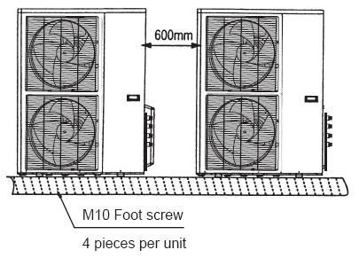
51 Installation 3. Installation 3.1 Choice of installation site Before installing the unit, agree with the customer the site where it will be installed, taking the following points into consideration: - check that the fixing points are adequate to support the weight of the unit; - pay scrupulous respect to safety distances between the unit and other equipment or structures to ensure that air entering the unit and discharged by the fans is free to circulate. 3.2 Positioning Before handling the unit, check the capacity of the lifting equipment used, respecting the instructions on the packaging. To move the unit in the horizontal, make appropriate use of a lift truck or similar, bearing in mind the weight distribution of the unit. To lift the unit, insert tubes long enough to allow positioning of the lifting slings and safety pins in the feet on the unit. To avoid the slings damaging the unit, place protection between the slings and the unit. Position the unit in the site indicated by the customer. Place either a layer of rubber (min. thickness 10 mm) or vibration damper feet (optional) between the base and support surface. Fix the unit, making sure it is level and that there is easy access to hydraulic and electrical components. If the site of installation is exposed to strong winds, fix the unit adequately to the support surface using tie rods if necessary. If a heat pump unit is being installed, make sure the condensate is drained using the drain hose supplied as standard. Prevent leaves, branches or snow from accumulating around the unit. These could reduce the efficiency of the unit. 3.3 Installation of outdoor unit Installation space 1) At least 600mm distance should be left between outdoor units: 2) Distance between foot screws is shown below: Installation 49

52 Installation Refrigerant Piping te: 1. Refrigerant piping connection is on the right side of outdoor unit. 2. The piping connects to refrigerant piping connection. 3. Install the refrigerant piping towards left, right or back. 4. Refer to system identifiers in valve installation board for corresponding connections of indoor units. a. Choose the sizes of refrigerant piping: φ9.5+φ19 b. Connection: refer to connection of refrigerant piping c. Length and height drop permitted of refrigerant piping Maximum length of piping (L) Maximum height drop (Height drop between water pump box and outdoor unit H) Outdoor unit (up) Outdoor unit (down) 10m 5m 5m d. Remove dirt or water in the piping Make sure there is no any dirt or water in the piping before connecting it to the outdoor unit. Please clean the piping with high-pressure nitrogen rather than refrigerant of outdoor unit. e. Vacuuming with vacuum pump Please vacuum with vacuum pump. Vacuuming should be done from the gas side. f. Open all valves g. Refrigerant volume to be added Calculate the volume according to the diameter and the length of the liquid side piping between outdoor unit and water pump box. The refrigerant volume to be added is based on the following table: Piping on liquid side Method Refrigerant volume to be added <5m Use refrigerant in outdoor unit 5m Use vacuum pump or refrigerant box 60g/m (length of piping -5m) Expel the air 1. Flaring Cut a pipe with a pipe cutter. Insert a flare nut into a pipe and flare the pipe. 2. Fasten the nuts Put the connecting tubing at the proper position, wrench the nuts with hands then fasten it with a wrench. 50 Installation
53 Installation Caution Too large torque will harm the bell-mouth and too small will cause leakage. Please determine the torque according to the table below: Pipe gauge Tightening torque Flare dimension A Min (mm) Max Flare shape Φ6.4 15~16N.m (153~163kgf.cm) Φ9.5 25~26N.m (255~265kgf.cm) Φ ~36N.m (357~367kgf.cm) Φ ~47N.m (459~480kgf.cm) Φ ~67N.m (663~684kgf.cm) How to expel the air A. Expel the air with refrigerant in outdoor unit: connect the wiring between water pump box and outdoor unit, refer to the example below: 1. Totally fasten the joint nut of stop valve B and nut C and D. 2. Loosen the joint nut of stop valve A a little. 3. For 3~5m s piping, turn the valve rod of B anticlockwise to 45 for about 6~7seconds. After the air is expelled from A, fasten the joint nut of stop valve A. (Refer to former page for the torque) 4. Totally open the valve rods of stop valve A and B. 5. Totally fasten the valve bonnet. B. Expel the air with vacuum pump (following procedures are for all the Lo-stop valve) 1. Connect the charging hose of the manifold valve with the charging inlet of the Lo-stop valve. (All the Hi-stop valves should be closed) 2. Connect the connection of charge hose with vacuum pump. 3. Totally open the Lo-lever of the manifold valve. 4. Turn on the vacuum pump. First loosen the joint nut of Lo-stop valve a little to check whether the air comes in (the noise of vacuum pump changes and the indicator of multi-meter turns to be above 0). Then fasten the joint nut. Installation 51
54 Installation 5. After vacuuming, close the Lo-lever of manifold valve and turn off vacuum pump. When doing vacuuming for more than 15 minutes, please confirm that the indicator of multi-meter points to-1.0x10⁵pa(-76cmhg) 6. Totally open the Hi-stop valve and Lo-stop valve. 7. Remove the charge hose from the charging inlet of Lo-stop valve. 8. Fasten the valve bonnets on Hi-stop valve, Lo-stop valve and on the charging inlet of Lo-stop valve. C. Expel air with refrigerant container 1. Connect the charge hose of refrigerant container with charging inlet of Lo-stop valve. 2. Fasten the joint nuts C, D and the joint nut of stop valve A. 3. Loosen the joint nut of stop valve B a little. 4. Open the valve of refrigerant container, after the refrigerant air is expelled from joint nut on Hi-stop valve side for 10~15 seconds, fasten the joint nut of stop valve B. 5. Remove the charge hose from the connection of Lo-stop valve and push the air valve core with a screw driver to discharge the refrigerant from piping until there is no noise. Then put back the air valve core at once in case the air goes into the system. 6. Remove the valve bonnet and totally open the stop valve B on high-pressure side and the valve rod on low-pressure side of the outdoor unit, then fasten the valve bonnet. 7. Make sure to fasten the valve bonnets of both Hi-stop valve and Lo-stop valve. 3.4 Installation of water pump box Installation location Please keep away from the following places: Such places where the temperature is high, water pump box can be installed outdoors. In other places, please install it indoors, such as washroom and the places that prevents it from water. There is combustible gas leakage. There is much salty ingredients. There is caustic gas such sulfide in the air. (The copper tubes and welding parts will be rusted and damaged, causing refrigerant to leak.) There is mineral oil, cooking oil or gasoline. (This may cause damage to plastic parts, looseness of components and leakage. A place that is too weak to bear the weight of water pump box. There is equipment that produces electromagnetic wave. (It will disturb the controlling system of air conditioner.) Install the refrigerant piping Check whether the height drop between water pump container and outdoor unit, the length of refrigerant piping, and the quantity of the bends meet the following requirements: The Max. Height drop 5m (if longer than 5m, outdoor unit should be above the water pump container.); The length of refrigerant piping shorter than 10m; The quantity of bends fewer than 15. Do not let air, dust, moisture or other impurities fall in the piping system during installation. Fix the outdoor unit and water pump box before installing the refrigerant piping. The refrigerant piping should not be installed until you check that the H-stop valve and Lo-stop valve or outdoor unit have been closed. 52 Installation
55 Installation The procedures for connecting pipe 1) Connect the water inlets and water outlets of water pump box and indoor unit with soft connection and charge water into the pipe to check whether there is leakage. Then connect the outdoor unit piping. Bend the piping carefully and do not damage them. 2) The stop valve of the outdoor unit should be closed absolutely (as original state). Every time you connect it, remove the nut of stop valve then connect the flaring pipe immediately (with 5 minutes). Before connecting, use refrigerant to expel the air in the pipe. 3) Connect the Hi-stop valve and Lo-stop valve of A and B system in outdoor unit to water pump box with piping. Make sure that the connection of both outdoor unit and water pump box should be corresponding. 4) The flexible pipe should be used on water pump side. (The bending angle should not exceed 90. The bending part is preferably in the middle of the pipe, the bigger the bending radius, the better it is. Do not bend the pipe more than 3 times.) 5) Bending the connecting pipe of thin wall. Cut out a desired concave at the bending part of the insulating pipe. To avoid distortion or damage, please bend the pipe at its biggest radius. Use bender to get a pipe with small radius. te: Make sure to use insulation material for the copper tube which you purchase by yourself. Installation 53
56 Hydraulic Connection 4. Hydraulic Connection The choice and installation of components is the responsibility of the installer who should follow good working practice and current legislation. Before connecting the pipes, make sure they do not contain stones, sand, rust, dross or other foreign bodies which might damage the unit. Construction of a bypass is recommended to enable the pipes to be washed through without having to disconnect the unit (see drain valves). The connection piping should be supported in such a way as to avoid it weighing on the unit. It is recommended that the following devices are installed in the water circuit of the evaporator: A hydraulic safety valve shall be mounted in water system, which should open constantly. 1. Two pressure gauges with a suitable scale (inlet and outlet). 2. Two vibration damper joints (inlet and outlet). 3. Two gate valves (normal inlet and calibrating in outlet) 4. A flow switch (inlet) or a differential pressure switch (inlet-outlet). 5. Two thermometers (inlet and outlet). 6. An inlet filter as close as possible to the evaporator and positioned to allow easy access for routine maintenance. 7. An energy-saving water tank. 8. Additional pump. 1) The chillers must be provided with a filling/top-up system connected to the return line and a drain cock in the lowest part of the installation. Installations containing anti-freeze or covered by specific legislation must be fitted with hydraulic disconnections. 2) The manufacturer is not liable for obstruction, breakage or noise resulting from the failure to install filters or vibration dampers. Particular types of water used for filling or topping up must be treated with appropriate treatment systems. For reference values, see the table. P H 6-8 Electrical conductivity less than 200 mv/cm (25 C ) Chlorine ions less than 50 ppm Sulphuric acid ions less than 50 ppm Total iron less than 0.3 ppm Alkalinity M less than 50 ppm Total hardness less than 50 ppm Sulphur ions none Ammonia ions none Silicon ions less than 30ppm 54 Installation
57 Hydraulic Connection Filling the installation - Before filling, check that the installation drain cock is closed. - Open all installation and terminal air vents. - Open the gate valves. - Begin filling, slowly opening the water filling cock outside the unit - When water begins to leak out of the terminal air vent valves, close them and continue filling until the pressure gauge indicates a pressure of 1.5 bars. Emptying the installation - Before emptying, place the mains switch in the off position - Make sure the installation fill/top-up water cock is closed - Open the drain cock outside the unit and all the installation and terminal air vent valves. Size and position of connections Model MGA-D10/N1 MGA-D12/N1 MGA-D14/SN1 MGA-D16/SN1 Water inlet/outlet (Ø) R5/4 R5/4 R5/4 R5/4 Auto-water replenishing(ø) R1/2 R1/2 R1/2 R1/2 Security discharge(ø) G1/2 G1/2 G1/2 G1/2 Mesh filter (Ø ) R5/4 R5/4 R5/4 R5/4 Air vent (Ø ) G3/8 G3/8 G3/8 G3/8 a) The installation must be filled to a pressure of between 1 and 2 bars. b) It is recommended that this operation be repeated after the unit has been operating for a number of hours. The pressure of the installation should be checked regularly and if it drops below 1 bar, the water content should be topped-up. c) Check the hydraulic tightness of joints. d) If the fluid in the circuit contains anti-freeze, it should not be allowed to drain freely as it is pollutant. It should be collected for possible reuse. When draining after heat pump operation, take care as the water may be hot (up to 50 ). Installation 55

58 Electrical Connection 5. Electrical Connection 5.1 tice The split mini chillers leave the factory already wired, and require the installation of an omnipolar thermal overload switch, a lockable mains disconnecting switch for the connection to the mains power supply, and the connection of the flow switch to the corresponding terminals. All the above operations must be carried out by qualified personnel in compliance with the legislation in force. For all electrical work, refer to the electrical wiring diagrams in this manual. You are also recommended to check that the characteristics of the mains electricity supply are adequate for the absorptions indicated in the electrical characteristics table below, also bearing in mind the possible use of other equipment at the same time. Power to the unit must be turned on only after installation work (hydraulic and electrical) has been completed. All electrical connections must be carried out by qualified personnel in accordance with legislation in force in the country concerned. Respect instructions for connecting phase, neutral and earth conductors. The power line should be fitted upstream with a suitable device to protect against short-circuits and leakage to earth, isolating the installation from other equipment. Voltage must be within a tolerance of ±10% of the rated power supply voltage for the unit (for three phase units, the unbalance between the phases must not exceed 3%). If these parameters are not respected, contact the electricity supply company. For electrical connections, use double insulation cable in conformity with current legislation in the country concerned. An omnipolar thermal overload switch and a lockable mains disconnecting switch, in compliance with the CEI-EN standards (contact opening of at least 3mm), with adequate switching and residual current protection capacity based on the electrical data table shown below, must be installed as near as possible to the appliance. The appliance shall be installed in accordance with national wiring regulations. The power cord technical data type and connection diagram should be list in the user manual. The power cord type designation is H07RN-F. An all-pole disconnection device which has at least 3mm separation distance in all pole and a residual current device(rcd)with the rating of above 10mA shall be incorporated in the fixed wiring according to the national rule. Do not use water pipes to earth the unit. 5.2 Electrical Panel The electrical panel is located inside the unit at the top of the technical compartment where the variouscomponents of the refrigerant circuit are also to be found. To access the electrical panel, remove the front panel of the unit by undoing the screws. 56 Installation
Content. The specifications, designs, and information in this book are subject to change without notice for product improvement.
 MCAC-ATSM-2014-01 Content R410A Mini Split Chiller 50Hz 1. Model Names of Outdoor Units... 2 2. External Appearance... 2 3. menclature... 3 4. Features... 4 5. Descriptions of Standard Unit... 6 6. Specifications...
Contents. Part 1 General Information...2 Part 2 Outdoor units...7 Part 3 Installation...63 Part 4 Controller...79
 MCAC-TSM-2008-02 Contents Part 1 General Information...2 Part 2 Outdoor units...7 Part 3 Installation...63 Part 4 Controller...79 Contents i MCAC-TSM-2008-02 Introduction Introduction Midea Mini Unitary
Mini unitary chiller. Mini unitary chiller
 Mini unitary chiller Mini unitary chiller Product description Features and benefits Description of main components Specification Operation limits Hydraulic performance Dimension Service space Piping diagram
Aqua Mini Full DC Inverter Unitary Chiller 50Hz. Content
 MCAC-ATSM-2014-09 Content 1. Outdoor units lineup... 2 2. Nomenclature... 3 3.Features... 4 4. Description of main components... 8 5. Specifications... 10 6. Dimensions... 14 7. Piping Diagram... 15 8.
MINI CHILLER INVERTER H4 Service manual MUENR-H4 (5, 7, 10, 12, 14, 16 kw)
") MINI CHILLER INVERTER H4 Service manual MUENR-H4 (5, 7, 10, 12, 14, 16 kw) CL25610 to CL25615 English Content 1. Outdoor units lineup... 2 2. Nomenclature... 3 3.Features... 4 4. Description of main components...
MINI CHILLER INVERTER H4 Service manual MUENR-H4 (5, 7, 10, 12, 14, 16 kw) CL25610 to CL25615 English Content 1. Outdoor units lineup... 2 2. Nomenclature... 3 3.Features... 4 4. Description of main components...
Mini Spilt Chiller &Mini Unitary Chiller 50Hz 2012
 MCAC Mini Spilt Chiller &Mini Unitary Chiller Hz Coercial Air Conditioner Business Units Midea Air Conditioning and Refrigeration Sector Add: est region of Midea coercial air conditioner department, Industry
Service manual. MIV V4+ Mini
 DM12-01.01.05en Service manual MIV V4+ Mini DC INVERTER R410A (~220V, 50Hz, 1Ph) MVUH80A-VA1 Contents Part 1 General Information... 1 Part 2 Outdoor Units... 6 Part 3 Installation... 44 DM12-01.01.05en
UCV CONDENSING UNITS SPECIFICATIONS 1. Specifications
 UCV CONDENSING UNITS SPECIFICATIONS 1. Specifications Model UCV-76C UCV-96C Code 220075900040 220075900020 Power supply V- Ph-Hz 380-415~3~50 Capacity Btu/h 76000 96000 Cooling Input W 8100 10000 Rated
Floor-Standing Type(E Series)
") Floor-Standing Type(E Series) Model: MFE-60CE, MFE-60AE Part 1. Product Features With a spiral shape, the computer-aided simulation designed air passage system can efficiently reduce noise. The Soft touch
Floor-Standing Type(E Series) Model: MFE-60CE, MFE-60AE Part 1. Product Features With a spiral shape, the computer-aided simulation designed air passage system can efficiently reduce noise. The Soft touch
[U] Serie MOV. Manual de Ingeniería
![[U] Serie MOV. Manual de Ingeniería](/thumbs/82/86228730.jpg "[U] Serie MOV. Manual de Ingeniería") [U] Serie MOV Uniidades Condensadoras (Fllujjo Verttiicall) 6..3,, 8 y 12..5 Ton Manual de Ingeniería - 112- Outdoor Units_MOV 1. Specifications.... 2. Dimension... 3. Service Space. 4. Piping Diagrams
[U] Serie MOV Uniidades Condensadoras (Fllujjo Verttiicall) 6..3,, 8 y 12..5 Ton Manual de Ingeniería - 112- Outdoor Units_MOV 1. Specifications.... 2. Dimension... 3. Service Space. 4. Piping Diagrams
Service Manual. Air Conditional
 Air Conditional Service Manual Большая библиотека технической документации http://splitoff.ru/tehn-doc.html каталоги, инструкции, сервисные мануалы, схемы. -2 - MODEL: AC-FR30CM -3 - CONTENTS SPECIFICATION...
MANUAL DE INGENIERIA. Part 1 General Information... 1 Part 2 Indoor Units... 6 Part 3 Outdoor Units... 30
 MANUAL DE INGENIERIA Evaporadora Sopladora 'MVA' con Condensadora 'MOV' - Blue Star Part 1 General Information... 1 Part 2 Indoor Units... 6 Part 3 Outdoor Units... 30 Part 1 General Information 1. Model
Product Data. Features/Benefits. 30RQ Air-cooled Modular Chiller R22 & R410A & R407C
 Product Data 30RQ Air-cooled Modular Chiller R22 & R410A & R407C Introduction Air-cooled modular chiller is a kind of central airconditioning unit which adopts air as the cooling (or heating) source and
Midea R410A Tropical ClimaCreator Series Rooftop Package 220V 3Ph 60Hz Technical Manual
 Midea R410A Tropical ClimaCreator Series Rooftop Package 220V 3Ph 60Hz Technical Manual Midea reserves the right to discontinue, or change specification or designs at any time without notices and without
Part 1 General Information... 1 Part 2 Indoor Units... 7 Part 3 Outdoor Units Part 4 Installation Part 5 Control...
 MCAC-UTSM-2008-11 Contents Part 1 General Information... 1 Part 2 Indoor Units... 7 Part 3 Outdoor Units... 88 Part 4 Installation... 127 Part 5 Control... 136 The specifications, designs, and information
R22 air-cooled modular chiller 50Hz unit. Content
 Content 1.Nomenclature... 2 2.Product Schedule... 2. External Appearance... 4.Features... 4 5.Specification... 6 6.Dimension... 10 7.Refrigeration System Sketch Drawing... 14 8.Wiring Diagrams... 16 9.Electric
SMART. 4,9 49,5 kw. Air cooled liquid chillers and heat pumps equipped with scroll compressor and axial fans T_SMT_0609_GB
 T_SMT_0609_GB 4,9 49,5 kw Air cooled liquid chillers and heat pumps equipped with scroll compressor and axial fans INDEX SERIES IDENTIFICATION... 3 MODEL IDENTIFICATION... 3 CE CONFORMITY... 3 WORKING
Wired controller KJR-08B/BE. Run. Fault. TB Tot. Out. Query. Heat. Net-On. Turn-On Mode
 R0A (kw-0kw) 0Hz KJR-0B/BE is a human-machine interaction(hmi) used for the communication between chiller operator and main board on the chiller itself. The setting and operation order can be send to the
CHGV AIR COOLED WATER CHILLER WITH HYDRAULIC EQUIPMENT AIR / WATER 47 to 78 kw
 TECHNICAL INSTRUCTIONS CHGV AIR COOLED WATER CHILLER WITH HYDRAULIC EQUIPMENT AIR / WATER 47 to 78 kw CHGV CHGV 64 CHGV 72 CHGV 80 PHRV heat pump model also available May 2006 10 12 167 - GB - 00 MARKING
AIR COOLED FREE-COOLING CHILLERS WITH SCROLL COMPRESSORS AND AXIAL FANS
 RAE 1352 F.K + MV AIR R-407C FC Series RAE... F.K Cooling capacity from 77 to 289 kw - 2 circuits The air cooled chillers of RAE... F.K series, are designed for outdoor installation and are particularly
COMMERCIAL AIR CONDITIONERS. Aqua Mini Chiller 50/60Hz
 COMMERCIAL AIR CONDITIONERS Aqua Mini Chiller 50/0Hz Midea CAC (MCAC) As a key subsidiary of Midea Group, the Midea Central Air Conditioner (MCAC) business unit has emerged as a leading supplier of commercial
SERVICE MANUAL CONDENSING UNIT ASE-18AH, ASE-24AH, ASE-36AH, ASE-48AH, ASE-60AH
 SERVICE MANUAL CONDENSING UNIT ASE-18AH, ASE-24AH, ASE-36AH, ASE-48AH, ASE-60AH Outdoor Units - appearance 18,000Btu/h 30,000~36,000Btu/h 24,000Btu/h 48,000Btu/h-60,000Btu/h Model Names of Outdoor Units
MODULAR CHILLER. R410a R22
 Ra R 3 Ra/-0 R/-0 New ppearance New Y-shape design, more fashion IR-COOLED SERIES (Ra) Compressor ir cooling side heat exchanger Best scroll compressor, low sound power level, By using calculation model
Air Cooled Scroll Chiller
 Air Cooled Scroll Chiller Midea chillers use H shape heat at air side and single unit s capacity from kw to 0kW. Super chillers are divided to SS,SS-LA, SP-LA and SP-HMLA series according to their water
SLS 1202 to With or without total heat recovery. u Air Cooled Screw Chillers. 262 to 916 kw. Engineering Data Manual
 u Air Cooled Screw Chillers SLS 1202 to 4004 With or without total heat recovery 262 to 916 kw Engineering Data Manual EDM SLS407-A.4GB Date : December 2008 Supersedes : TM SLS407-A.3GB/11.06 Specifications
Amendment Sheet. Nomenclature M 5 AC V 100 C R - F X AA. Code : M5ACV Date : Superceded : M5ACV
 Amendment Sheet Code : M5ACV-2005-0002 Date : 08-05-2006 Superceded : M5ACV-2005-0001 Nomenclature Production spec variation Type of ref. connection X : Not applicable Electrical A : 220-240V/1Ph/50Hz
SERVICE MANUAL 42QHF009DS* 42QHF012DS* 42QHF018DS* 42QHF022DS* 38QUS009DS* 38QUS012DS* 38QUS018DS* 38QUS022DS* Indoor unit.
 SERVICE MANUAL Indoor unit Outdoor unit 42QHF009DS* 42QHF012DS* 42QHF018DS* 42QHF022DS* 38QUS009DS* 38QUS012DS* 38QUS018DS* 38QUS022DS* INDEX PART1 GENERAL INFORMATION PART2 ELECTRICAL DIAGRAM PART3 TROUBLE
AIR COOLED CHILLERS WITH SCROLL COMPRESSORS AND CENTRIFUGAL FANS
 RAE 201 C K RAE 482 C K AIR R-407C Series RAE... C K from 19 to 83 kw - 1 and 2 circuits The air cooled chillers of RAE... C K series, with centrifugal fans, are designed for indoor installation and are
Epsilon Echos kw. General information Air-Water unit with scroll compressors driven by DC inverter. Unique selling points
 Epsilon Echos+ 5 38 kw General information Air-Water unit with scroll compressors driven by DC inverter Configuration /LN: Low noise unit /HP: Reversible heat pump /LE /HP: Reversible condensing unit Unique
MULTIPLO PF Multifunction chillers for indoor installation. Cooling Capacity: kw Heating Capacity: kw
 Multifunction chillers for indoor installation. Cooling Capacity: 22 222 Heating Capacity: 25 236 Scroll compressors EC Plug Fans Plate type heat exchangers EER up to 3,12 COP up to 3,84 ESEER up to 4,01
CHGV AIR COOLED WATER CHILLER WITH HYDRAULIC EQUIPMENT AIR / WATER 47 to 78 kw
 TECHNICAL INSTRUCTIONS CHGV AIR COOLED WATER CHILLER WITH HYDRAULIC EQUIPMENT AIR / WATER 47 to 78 kw CHGV 50 CHGV 64 CHGV 72 CHGV 80 PHRV heat pump model also available November 2007 10 12 167 - GB -
CHGV AIR COOLED WATER CHILLER WITH HYDRAULIC EQUIPMENT AIR / WATER 21 to 39 kw
 TECHNICAL INSTRUCTIONS CHGV AIR COOLED WATER CHILLER WITH HYDRAULIC EQUIPMENT AIR / WATER 21 to 39 kw CHGV 22 CHGV 2 CHGV 32 CHGV 40 PHRV heat pump model also available September 2007 10 12 11 - GB - 02
Ultimate energy saving technology
 Ultimate energy saving technology CWT Chiller Series CWt purestream series water chillers The new CWT Purestream chiller range is specifically designed to meet the stringent cooling requirements of today
DYNACIAT LGN. Description. Split system Water chillers. High energy efficiency Compact and quiet Scroll compressors Brazed-plate heat exchangers
 High energy efficiency Compact and quiet Scroll compressors Brazed-plate heat exchangers Self-adjusting electronic control Cooling capacity: 35 to 700 kw 410A Cooling Operation DYNACIAT - DYNACIAT POWER
AIR COOLED CHILLERS WITH SCROLL COMPRESSORS AND CENTRIFUGAL FANS
 RAE 1402 C O K AIR R-407C Series RAE... C K Cooling capacity from 81 to 250 kw - 2 circuits The air cooled chillers of RAE C K series, with centrifugal fans, are designed for indoor installation and are
Service Manual. Air Conditional
 Air Conditional Service Manual Большая библиотека технической документации http://splitoff.ru/tehn-doc.html каталоги, инструкции, сервисные мануалы, схемы. -2 - MODEL: AC-FR30HM -3 - CONTENTS SPECIFICATION...
Klimaire 16 SEER CENTRAL DUCTED YEAR. Central Air Conditioning & Heat Pump Systems Multi Position Air Handling Units LIMITED GUARANTEE
 Klimaire 16 SEER CENTRAL DUCTED Central Air Conditioning & Heat Pump Systems Multi Position Air Handling Units 10 YEAR LIMITED GUARANTEE R410A R E F R I G E R A N T CSM Condensing Units Features Condensing
AIR COOLED CHILLERS FOR OUTDOOR INSTALLATION WITH INTEGRATED FREE COOLING MULTISCROLL SERIES
 AIR COOLED CHILLERS FOR OUTDOOR INSTALLATION WITH INTEGRATED FREE COOLING MULTISCROLL SERIES COOLING CAPACITY FROM 76 TO 612 Kw 1 AND 2 COOLING CIRCUITS RAE 1702 F Kc + P2 28 Above picture is only indicative
Ultimate energy saving technology
 Ultimate energy saving technology CWT Chiller Series CWt purestream series water chillers The new CWT Purestream chiller range is specifically designed to meet the stringent cooling requirements of today
Service Manual. Multi Split Type Heat Pump Air Conditioners. Applied to: HS-9U2IM_HOS-18U2IM HS-9U11IM_HS-12U11IM_HOS-21U11IM
 Service Manual Multi Split Type Heat Pump Air Conditioners Applied to: HS-9U2IM_HOS-18U2IM HS-9U11IM_HS-12U11IM_HOS-21U11IM CONTENT 1. Product features 2. Specification 3. Dimensions 4. Refrigeration cycle
MODEL: CCT 301 INV CCT 501 INV CCT 70 INV-S CCT 100 INV-S CCT 140 INV-S CCT 170 INV-S
 MODEL: CCT 301 INV CCT 501 INV CCT 70 INV-S CCT 100 INV-S CCT 140 INV-S CCT 170 INV-S Compact Four-way Cassette Type 1. Features... 2. Specification... 3. Dimension... 4. Service Space... 5. Wiring Diagram...
SELF-PRIMING JET PUMPS
 SS Anti-Rust SS Shaft Copper & Cold-rolled SELF-PRIMING JET PUMPS CONTENTS 1. Applications.... Model Description.... Technical Data... 4. Implementation Standards... 5. Safety Precautions... 6. Product
WATER COOLED HEAT PUMP VERTICAL UNIT CONSOLE TYPE OR RECESSED
 EQV R-407C WATER COOLED HEAT PUMP VERTICAL UNIT CONSOLE TYPE OR RECESSED Size Cooling Heating [kw] [kw] 5 1,9 2,2 7 2,4 2,5 9 2,6 2,5 15 3,3 3,2 17 3,7 3,7 REPLACE: BT02E008GB-01 The Versatemp EQV units
Zeta Rev LN HP Prochill Bluebox Print Date: 07/17/2017
 Zeta Rev LN HP 10.2 Configured unit accessories 1PS - One user-side pump with tank LN - Low noise RG - Condensation control with fan speed regulator CSP - Set point compensation depending on external air
30GH Air-Cooled Liquid Chillers 30GH Nominal cooling capacity kw
 Air-Cooled Liquid Chillers Nominal cooling capacity 21-94 kw Carrier is participating in the Eurovent Certification Programme. Products are as listed in the Eurovent Directory of Certified Products. The
Service Manual & Installation Manual
 GE Consumer & Industrial Appliances Service Manual & Installation Manual Split System Air Conditioner Model numbers: GE AIR F24 GE AIR F34 GE AIR F41 1 2 3 Introduction and Features Model Remarks GE AIR
Room Air Conditioner Service and Parts Manual
 Cool Dry Temp Mode Room Air Conditioner Service and Parts Manual F Fan Speed hr Timer 0n 0ff Money Saver Fan Only Auto Swing Power CP06 CP08 93011401_01 CONTENTS 1. PREFACE 1.1 SAFETY PRECAUTIONS...2 1.2
Ceiling & Floor type Unit
 Ceiling & Floor type Unit Part 1. Product Features Quietest operation, low noise. Thin design, space-saving. Easy to operate, remote control. 16 Part 2. Specification Model MUA-18HRN2 MUA-24HRN2 MUA-24HRN2
RAH Ka AIR COOLED WATER CHILLERS WITH SCREW COMPRESSORS AND AXIAL FANS. COOLING CAPACITY FROM 387 TO 1207 kw 1 AND 2 COOLING CIRCUITS
 AIR COOLED WATER CHILLERS WITH SCREW COMPRESSORS AND AXIAL FANS COOLING CAPACITY FROM 387 TO 1207 kw 1 AND 2 COOLING CIRCUITS RAH 602 Ka + CF + GP 62 Above picture is only indicative and is not binding.
GPE Kc UNITS FOR 4-PIPE SYSTEMS WITH SCROLL COMPRESSORS. COOLING CAPACITY FROM 77 TO 426 kw - 2 COOLING CIRCUITS. GPE 802 Kc + CF + GP + MV + P1
 UNITS FOR 4-PIPE SYSTEMS WITH SCROLL COMPRESSORS COOLING CAPACITY FROM 77 TO 426 kw - 2 COOLING CIRCUITS GPE 802 Kc + CF + GP + MV + P1 130 Above picture is only indicative and is not binding. AIR R-410A
Next P kw COOLING 5 93 kw HEATING. technicalcatalogue. Heat pump air conditioners with upflow air delivery T_NXTP_0411_GB
 Next P 6 112 kw COOLING 5 93 kw HEATING Heat pump air conditioners with upflow air delivery technicalcatalogue T_NXTP_0411_GB INDEX GENERAL CHARACTERISTICS... 3 SERIES IDENTIFICATION... 4 MODEL IDENTIFICATION...
.2 Section Waste Management and Disposal.
 Issued 2005/06/01 Section 15624 Packaged Rotary Screw Water Chillers Page 1 of 5 PART 1 General 1.1 RELATED SECTIONS.1 Section 01330 Submittal Procedures..2 Section 01355 Waste Management and Disposal..3
1. Outdoor units lineup
 Content 1. OUTDOOR UNITS LINEUP... 2 2. NOMENCLATURE... 3 3. FEATURES... 4 4. DESCRIPTION OF MAIN COMPONENTS... 7 5. SPECIFICATIONS... 9 6. DIMENSIONS... 13 7. PIPING DIAGRAM... 14 8. WIRING DIAGRAM...
COOLROW Close control air conditioners for In-Row installation Cooling Capacity: kw
 COOLROW Close control air conditioners for In-Row installation Cooling Capacity: 14 61 Available in versions equipped with: - BLDC inverter scroll compressor on board of the unit - Chilled water feeding
Air-Cooled Mini Chiller. Models: AMAC 040 A/AR AMAC 050 A/AR AMAC 058 A/AR AMAC 075 B/BR AMAC 100 B/BR AMAC 125 B/BR. Manual No: TMA-AMAC-1161
 Models: AMAC 040 A/AR AMAC 050 A/AR AMAC 058 A/AR AMAC 075 B/BR AMAC 100 B/BR AMAC 125 B/BR Air-Cooled Mini Chiller Manual No: TMA-AMAC-1161 REGISTERED ISO 9002 CONTENTS PAGE 1. NOMENCLATURE SYSTEM...
BRAN Residential chillers and heat pumps. Reversible unit, air source for outdoor installation 4,81-27,2 kw <<< BACK INDEX.

Air cooled industrial chillers
 Air cooled industrial chillers Main features R410A refrigerant Cooling capacity 5 175 kw Air cooled industrial chillers Models Versions HE High Efficiency Finned coil evaporators submerged in the storage
inverter mini chiller
 inverter mini chiller TRUST AIR CONDITIONING EQUIPMENT CO. Prepared By: Engineering & R & D Department. Shiraz- May 2017 Content 1. OUTDOOR UNITS LINEUP... 2 2. FEATURES... 3 3. DESCRIPTION OF MAIN COMPONENTS...
Technical Support Division GD CHIGO HEATING & VENTILATION EQUIPMENT CO., LTD.
 Technical Support Division 2017-4-25 New CMV System - Floor ceiling Indoor Unit 1 1. External appearance 2. Nomenclature 3. Specifications 4. Dimensions 5. Service space 6. Piping diagram 7. Wiring diagram
ULTIMATE ENERGY SAVING TECHNOLOGY
 ULTIMATE ENERGY SAVING TECHNOLOGY CWM CHILLER SERIES CWM PURESTREAM SERIES WATER CHILLERS The new CWM Purestream chiller range is specifically designed to meet the stringent cooling requirements of today
CMA CONDENSING UNITS FOR OUTDOOR INSTALLATION INSTALLATION AND OPERATION MANUAL
 CMA CONDENSING UNITS FOR OUTDOOR INSTALLATION ECO-FRIENDLY REFRIGERANT GAS INSTALLATION AND OPERATION MANUAL Dear Customer, Thank you for having purchased a FERROLI product. It is the result of many years
INTRODUCTION. Special Applications of Package Air Conditioners. Instant Cooling Requirement in Wedding Ceremonies
 Pakistan s Largest Manufacturers of Air-Conditioners PACKAGE TYPE UNIT FOR MOBILE APPLICATIONS Provides Turnkey Projects Conceptual Planning to Commissioning of HVACR Projects THE LARGEST MANUFACTURER
Acquaer Ltd. H-4900, Fehérgyarmat, Szatmári út 11. CENTRIFUGAL PUMP Instruction Manual ACm60 / ACm75 / ACm150 / ACm150B2
 CENTRIFUGAL PUMP Instruction Manual ACm60 / ACm75 / ACm150 / ACm150B2 Congratulations on your purchase of a LEO Centrifugal Pump It is important that you read, fully understand and observe the following
MACH N-407 Heat Pump Air-Cooled Chiller
 MACH060-01-N-407 Heat Pump Air-Cooled Chiller Heat Pump Air-Cooled Chillers for Global Residential and Light Commercial Microclimates MACH NOMENCLATURE BREAKDOWN MACH-060-01 - N - 407 Refrigerant Type
EASY_R R407C. Air cooled liquid chillers and heat pumps equipped with scroll compressor and axial fans. 5,2 41,5 kw T_ESY_R_0508_GB
 R407C EASY_R Air cooled liquid chillers and heat pumps equipped with scroll compressor and axial fans 5,2 41,5 kw T_ESY_R_0508_GB EASY_R R407C INDEX WORKING LIMITS... 3 SERIES IDENTIFICATION... 4 MODEL
FALCON Rooftop Units ACPSE 50/60Hz Cooling Capacity : 36 to 1388 MBH (11 to 407 kw) Heating Capacity : 40 to 1298 MBH (12 to 380 kw)
 Heating Capacity : 40 to 1298 MBH (12 to 380 kw)") FALCON Rooftop Units ACPSE 50/60Hz Cooling : 36 to 1388 MBH (11 to 407 ) Heating : 40 to 1298 MBH (12 to 380 ) R Products that perform...by people who care NOMENCLATURE 6 AC P S E 435 P - HP G Q 6-60 Hz
FALCON Rooftop Units ACPSE 50/60Hz Cooling : 36 to 1388 MBH (11 to 407 ) Heating : 40 to 1298 MBH (12 to 380 ) R Products that perform...by people who care NOMENCLATURE 6 AC P S E 435 P - HP G Q 6-60 Hz
AQH 40 to 130. u Air-to-Water Reverse Cycle Heat Pumps. 40 to 131 kw. 45 to 141 kw. Engineering Data Manual
 u Air-to-Water Reverse Cycle Heat Pumps AQH 40 to 130 40 to 131 kw 45 to 141 kw Engineering Data Manual EDM AQH-W.3GB Date : November 2007 Supersedes : TM AQH-W.2GB/03.04 Specifications The Aqu@Logic air-to-water
Air-to-water scroll chillers
 Air-to-water scroll chillers Model CGA 040 to 115 Cooling capacity: 14-40 kw CG-PRC031B-GB Table of Contents Technical specifications...4 Standard configuration... 4 Hydraulic version... 4 Casing... 4
Большая библиотека технической документации каталоги, инструкции, сервисные мануалы, схемы.
 Air Conditioner Service Manual Большая библиотека технической документации http://splitoff.ru/tehn-doc.html каталоги, инструкции, сервисные мануалы, схемы. 2 Model: AC-S10CG 3 Content Technical specification..
CHG AIR COOLED WATER CHILLER WITH CONDENSATION BY HELICOIDAL AIR 8 to 17 kw
 TECHNICAL INSTRUCTIONS CHG AIR COOLED WATER CHILLER WITH CONDENSATION BY HELICOIDAL AIR 8 to 17 kw CHG 1 CHG 1 8. kw. kw.7 kw 1. kw April 7 19 - GB - 2 MARKING This product marked conforms to the essential
Floor-Standing Type(S2 Series)
") Floor-Standing Type(S2 Series) Model: MFS2-24CR(N2), MFS2-24HR(N2), MFS2-24AR(N2), MFS2-48CR(N2), MFS2-48AR(N2) Part 1. Product Features Strong air supply. Wide angle and long distance air supply. Easy
Floor-Standing Type(S2 Series) Model: MFS2-24CR(N2), MFS2-24HR(N2), MFS2-24AR(N2), MFS2-48CR(N2), MFS2-48AR(N2) Part 1. Product Features Strong air supply. Wide angle and long distance air supply. Easy
Warning: 230V / 1ph / 50Hz V / 3ph / 50Hz. Remarks: Make sure that you have enough power. (See page 15 Cable table)
") 1 2 Warning: - Do not place your hand or any other objects into the air outlet and fan. It could damage the heat pump and cause injuries; - In case of any abnormality with the heat pump, cut off the power
1 2 Warning: - Do not place your hand or any other objects into the air outlet and fan. It could damage the heat pump and cause injuries; - In case of any abnormality with the heat pump, cut off the power
Part 5. Troubleshooting. 1. Normal Air Conditioner Phenomenon Air Conditioner Protection in Common
 Part 5 1. Normal Air Conditioner Phenomenon... 1611 2. Air Conditioner Protection in Common... 1611 3. Malfunction Code and... 162 160 1. Normal Air Conditioner Phenomenon 1.1 When outdoor unit appears
BRAT BRAN INSTALLATION, USER AND MAINTENANCE MANUAL
 INSTALLATION, USER AND MAINTENANCE MANUAL EN Air/water chillers and heat pumps with axial-flow fans with and without pump assemblies BRAT2 0021 0121 BRAN2 0021 0121 INDEX INDICE U General warnings 3 A
PDF Created with deskpdf PDF Writer - Trial ::
 Instruction Manual Index Introduction Uncrating and Checking for Damage Locating Your Unit Installation Fill Tank Process Connections Pre Startup Startup Sequence Trouble Shooting Chart Operating Lights
MAC N-407 Air-Cooled Chiller
 MAC036-01-N-407 Air-Cooled Chiller Air-Cooled Chillers for Global Residential and Light Commercial MicroClimates MAC036 NOMENCLATURE BREAKDOWN MAC036-01 - N - 407 Refrigerant Type Air-Cooled Chiller 036=
NEXT EVO DXR410A NEXT EVO DX NEW SOFTWARE. rcgroupairconditioning
 : Direct expansion close control air conditioners with up-flow or down-flow air delivery. Cooling Capacity: 7 102 NEW SOFTWARE R410A rcgroupairconditioning E C A C UP FLOW DOWN FLOW MAIN FEATURES Precision
Air Conditioner Service Manual
 Air Conditioner Service Manual Большая библиотека технической документации http://splitoff.ru/tehn-doc.html каталоги, инструкции, сервисные мануалы, схемы. 2 MODEL: AC-S7HGB 3 CONTENTS TECHNICAL SPECIFICATION..4
TECHNICAL, OPERATING & INSTALLATION MANUAL TC 15, 33, 52 AIR COOLED PACKAGED WATER CHILLERS
 TC SERIES OPTIONS TECHNICAL, OPERATING & INSTALLATION MANUAL TC 15,, 5 AIR COOLED PACKAGED WATER CHILLERS CONTENTS EQUIPMENT AND COMPONENT DETAILS PERFORMANCE AND TECHNICAL DATA SCHEMATIC FLOW & SYSTEM
Kälte Klima. Air cooled water chillers air cooled reversible heat pumps from 45 kw to 320 KW. Compressors Scroll SCAEY DE 88 04/11 12/10
 Air cooled water chillers air cooled reversible heat pumps from 45 kw to 320 KW Compressors Scroll Serie: Series: Emissione: Issue: SCAEY Catalogo: Leaflet: Sostituisce: Supersedes: DE 88 04/11 12/10 Index
Miraco MISR REFRIGERATION & AIR CONDITIONING MFG. CO.
 Miraco MISR REFRIGERATION & AIR CONDITIONING MFG. CO. High Efficiency Green Slim Line Ceiling Concealed Ducted Split Systems Cool Only Rev. August 2015 12K - 18K - 24K - 30K - 36K - 42K - 48K - 60K IAQ
Midea R410A Domestic Pools & Spas Heat Pump Water Heater 50Hz A1 Series Technical Manual
 Midea R410A Domestic Pools & Spas HPWH 50Hz Technical Manual MCAC-HTSM-201409 Midea R410A Domestic Pools & Spas Heat Pump Water Heater 50Hz A1 Series Technical Manual Applicable Model: (New CE safety directive)
DOLPHIN RADIATOR & COOLING SYSTEMS P.O.Box: 1424,Ph#: , Fax#: ,
 DOLPHIN RADIATOR & COOLING SYSTEMS P.O.Box: 1424,Ph#: +971-6-5432526, Fax#: +971-6-5432415, Email: dolcool@emirates.net.ae, web site: www.dolphinheattransfer.com NOMENCLATURE: INTRODUCTION DOLCOOL branded
Part 3 Troubleshooting
 Part Troubleshooting What is in this part? This part contains the following chapters: Chapter See page Troubleshooting 2 Error Codes: Hydro-box 7 Error Codes: Outdoor Units Error Codes: System Malfunctions
PHRT HEAT PUMP WITH HYDRAULIC EQUIPMENT AIR / WATER 9 to 18 KW
 TECHNICAL INSTRUCTIONS PHRT HEAT PUMP WITH HYDRAULIC EQUIPMENT AIR / WATER to KW PHRT PHRT PHRT PHRT For terminal units and boiler overhaul applications Heating Cooling PHRT.00 kw -. kw PHRT.0 kw /.0 kw
AGEO CALEO. Water-to-water high temperature heat pumps USE RANGE DESCRIPTION. Designed to replace a conventional boiler and produce domestic hot water
 Designed to replace a conventional boiler and produce domestic hot water Heating capacity : 16 to 25 Heating Hydraulic module ENVIRONMENTALLY HFC R4A PROTECTION DE FRIENDLY L'ENVIRONNEMENT USE CIAT is
WATER TO AIR DUCTABLE INDOOR HORIZONTAL HEAT PUMP
 EVH R-407C WATER TO AIR DUCTABLE INDOOR HORIZONTAL HEAT PUMP Size Cooling Heating [kw] [kw] 7 2.0 1.9 11 2.6 2.5 15 3.9 3.3 5.2 5.5 25 7.3 6.7 31 8.9 8.4 41 10.7 9.8 REPLACE: BT02E009GB-01 The Versatemp
NEMO A Split-system liquid chillers for indoor installation. Cooling Capacity: 5 26 kw
 Split-system liquid chillers for indoor installation. Cooling Capacity: 5 26 Built-in pumping group Scroll compressor Plate type heat exchanger EER up to 2,88 rcgroup.it Chillers : Motoevaporating units
Compact design & easy maintenance
 Compact design & easy maintenance 18 SEER MRCOOL Address: 1315 College Street Clarksville TN 37040 Email: sales@mrcool.com mrcool.com Specifications and appearance are subject to change without notice.
Contour TM Screw Compressors
 Contour TM Screw Compressors Semi-Hermetic Compact Operating Instruction SCH1 High Temp Compressors Form No. 99-77 1. Introduction This series of semi-hermetic compact screw compressors is designed for
Kälte Klima. Air cooled liquid chiller Free-Cooling from 45 kw to 365 kw. Scroll Compressors SCAEY-FC DE 98
 Air cooled liquid chiller Free-Cooling from 45 kw to 365 kw Scroll Compressors Series: SCAEY-FC Leaflet: DE 98 Issue: 04/11 Supersedes: 12/10 Identification code Index Index... pag. 2 Identification code...»
1. Product Lineup. 2. External Appearance. 3. Nomenclature M R C 36 H W N1 - R. Power supply R: 380~415V 3Ph~ 50Hz. Refrigerant type N1: R410A
 Contents 1. Product Lineup... 1 2. External Appearance... 1 3. Nomenclature... 1 4. Features... 2 5. List of Functions... 3 6. Specifications... 6 7. Dimensional Drawings... 8 8. Wiring Diagrams... 9 9.
B. Unit construction shall comply with ASHRAE 15 Safety Code, NEC, and ASME applicable codes (U.S.A. codes).
.") Guide Specifications PART 1 GENERAL 1.01 SYSTEM DESCRIPTION Microprocessor controlled, air-cooled liquid chiller utilizing scroll compressors, low sound fans, hydronic pump system and optional fluid storage
Guide Specifications PART 1 GENERAL 1.01 SYSTEM DESCRIPTION Microprocessor controlled, air-cooled liquid chiller utilizing scroll compressors, low sound fans, hydronic pump system and optional fluid storage
CW-5000/5200 Series Industrial Chiller maintenance manual
 CW-5000/5200 Series Industrial Chiller maintenance manual 1 目录 Ⅰ Chiller Alarm (red light on)--have water circulation P3-7 Ⅱ Chiller Alarm (red light on)--not water circulation P7-8 Ⅲ CW-5000 Series Temperature
WATER CHILLER UNITS AIR COOLED CONDENSER CENTRIFUGAL FANS HEAT PUMP. EWCBZ COOLING ONLY. EWCZ
 WATER CHILLER UNITS AIR COOLED CONDENSER CENTRIFUGAL FANS HEAT PUMP. EWCBZ COOLING ONLY. EWCZ SERIES: EWCBZ - Heat pump MODELS: 70, 80, 00, 0, 60, 00, 40, 00, 50 COOLING CAPACITIES from 5,9 kw to 78,5
Content. Part 1 General Information Part 2 Indoor Units Part 3 Outdoor Units Part 4 Installation Part 5 Control...
 R410A Tropical Split Type AC Technical Manual Content Content Part 1 General Information... 2 Part 2 Indoor Units... 6 Part 3 Outdoor Units... 88 Part 4 Installation... 120 Part 5 Control... 154 Indoor
DC INVERTER MULTI-SYSTEM AIR CONDITIONER
 TECHNICAL & SERVICE MANUAL OUTDOOR UNIT : CU-3KE19NBU CU-4KE24NBU CU-4KE31NBU DC INVERTER MULTI-SYSTEM AIR CONDITIONER Capacity at 0V 19,100 BTU/h,200 BTU/h 30,600 BTU/h Outdoor Model No. CU-3KE19NBU CU-4KE24NBU
AIR-CONDITIONER SERVICE MANUAL
 FILE NO. A90-9608 SERVICE MANUAL AIR-CONDITIONER S SPLIT BUILT-IN DUCT TYPE RAV-362B-PE/ RAV-462B-PE/ SPLIT CEILING TYPE RAV-362C-PE/ RAV-462C-PE/ SPLIT CASSETTE TYPE RAV-362U-PE/ RAV-462U-PE/ PRINTED
Local Air Conditioner
 Local Air Conditioner Thank you for selecting this air-conditioner. Please keep this User s Manual for future reference. Read the User s Manual carefully before operating this unit. IMPORTANT SAFEGUARDS
CMA TECHNICAL MANUAL CONDENSING UNITS FOR OUTDOOR INSTALLATION O L S A F RA N
 E S A RE F R E IG RA N T G TECHNICAL MANUAL -FRIEND Y CONDENSING UNITS FOR OUTDOOR INSTALLATION O L CMA C 2 The manufacturer declines all the responsabilities regarding inaccuracies contained in this manual,