SERVICE MANUAL CONDENSING UNIT ASE-18AH, ASE-24AH, ASE-36AH, ASE-48AH, ASE-60AH
|
|
|
- Prosper Bell
- 5 years ago
- Views:
Transcription


1 SERVICE MANUAL CONDENSING UNIT ASE-18AH, ASE-24AH, ASE-36AH, ASE-48AH, ASE-60AH
2


3 Outdoor Units - appearance 18,000Btu/h 30,000~36,000Btu/h 24,000Btu/h 48,000Btu/h-60,000Btu/h Model Names of Outdoor Units Universal Outdoor unit Model Compressor type Compressor Brand Heat Pump ASE-18AH Rotary GMCC ASE-24AH Rotary GMCC ASE-36AH SCROLL SANYO ASE-48AH SCROLL SANYO ASE-60AH SCROLL SANYO


4 Features High quality coils: The coil is constructed of advanced inner grooved copper tube and aluminum fins. Anti-rust, 500 hours salt spray test. Low operation sound level: Well-known stable and quiet running fan motor. Well-known compressor. Compact design: Smaller dimension and larger stuffing capacity. Universal outdoor unit design. Optional air outlet grille: plastic type and wire type. Wire type Plastic type Plastic type Optional low temperature cooling module. R410A environment friendly refrigerant.
5 Outdoor Units 1. Specifications Dimensions Service Space Wiring Diagrams Electric Characteristics Operation Limits Sound Levels Troubleshooting
6 Model ASE-18AH ASE-24AH Code Power supply V-ph-Hz 220~ ~ Max. input consumption W Max. input current A Compressor Outdoor fan motor Outdoor coil Model PA225X2CS-4KU1 PA290X3CS-4MU1 Type Rotary Rotary Brand GMCC GMCC Capacity Btu/h 18493/ Input W 1855/ Rated current(rla) A 8.7/ Locked rotor Amp(LRA) A Thermal protector Internal Internal Capacitor μf 50μF/440V-450V 50μF/440V-450V Refrigerant oil ml ESTER OIL VG ESTER OIL VG74/950 Model YDK48-6H(A) YDK100-6D Qty 1 1 Input W Capacitor μf 3μF/450V 5μF/450V Speed r/min Number of rows 2 2 Tube pitch(a) row pitch(b) mm 21x x13.37 Fin spacing mm Fin type Hydrophilic aluminium Hydrophilic aluminium Tube outside dia.and type mm φ7, Inner grooved copper φ7, Inner grooved copper tube tube Coil length height width mm 658x546x x651x26.74 Number of circuits 4 4 Outdoor air flow m 3 /h Outdoor noise level (sound pressure) db(a) Outdoor unit Dimension(W H D) mm 760x590x Packing (W H D) mm Net/Gross weight kg 39/42 53/57 Type R410a R410a Refrigerant Charged volume g Throttle type Capillary Capillary Design pressure MPa 4.2/ /1.5 Refrigerant piping Liquid side/ Gas side mm φ6.4/φ12.7 φ9.5/φ15.9 Max. pipe length m Max. difference in level m Ambient temp. cooling:18~43; heating:-7~24 cooling: 18~43; heating:-7~24 Notes: 1. Nominal cooling capacities are based on the following conditions: Indoor temp: 27 CDB, 19 CWB; Outdoor temp: 35 CDB; 2. Nominal heating capacities are based on the following conditions: Indoor temp: 20 CDB; Outdoor temp: 7 CDB, 6 CWB; 3. Actual noise level may differ, depending on the room structure, etc, since these noise values are from an anechoic room.
7 Model ASE-36AH Code Power supply V-ph-Hz 380~ Max. input consumption W 4950 Max. input current A 10 Compressor Outdoor fan motor Outdoor coil Model Type Brand C-SBN303H8D SCROLL SANYO Capacity Btu/h Input W 3650 Rated current(rla) A 6.58 Locked rotor Amp(LRA) A 48 Thermal protector Internal Capacitor μf -- Refrigerant oil ml FV68S/1700 Model YDK190-6D Qty 1 Input W 290 Capacitor μf 10μF/450V Speed r/min 840 Number of rows 2 Tube pitch(a) row pitch(b) mm 21x13.37 Fin spacing mm 1.4 Fin type Hydrophilic aluminium Tube outside dia.and mm type φ7, Inner grooved copper tube Coil length height mm 890x903x26.74 width Number of circuits 7 Outdoor air flow m 3 /h 5000 Outdoor noise level (sound pressure) db(a) 57 Outdoor unit Refrigerant Throttle type Dimension(W H D) mm Packing (W H D) mm Net/Gross weight kg 92/96 Type R410a Charged volume g 2900 capillary Design pressure MPa 4.2/1.5 Refrigerant piping Liquid side/ Gas side mm φ12.7/φ19 Max. pipe length m 30 Max. difference in level m 20 Ambient temp. cooling: 18~43; heating:-7~24 Notes: 1. Nominal cooling capacities are based on the following conditions: Indoor temp: 27 CDB, 19 CWB; Outdoor temp: 35 CDB; 2. Nominal heating capacities are based on the following conditions: Indoor temp: 20 CDB; Outdoor temp: 7 CDB, 6 CWB; 3. Actual noise level may differ, depending on the room structure, etc, since these noise values are from an anechoic room.
8 Model ASE-48AH ASE-60AH Code Power supply V-ph-Hz 380~ ~ Max. input consumption W Max. input current A Compressor Outdoor fan motor Outdoor coil Model C-SBN373H8D C-SBN453H8D Type Scroll Scroll Brand Sanyo Sanyo Capacity Btu/h Input W Rated current(rla) A Locked rotor Amp(LRA) A Thermal protector Internal Internal Capacitor μf Refrigerant oil ml FV68S,1700 FV68S, 1700 Model YDK YDK65-6F-1 YDK65-6+YDK65-6F Qty 2 2 Input W Capacitor μf (4μF/450V) 2 (3.5μF/450V) 2 Speed r/min Number of rows 2 2 Tube pitch(a) row pitch(b) mm Fin spacing mm Fin type Hydrophilic aluminium Hydrophilic aluminium Tube outside dia. and type Coil length height width mm φ7 Inner grooved copper tube φ7.94 Inner grooved copper tube mm Number of circuits 4 8 Outdoor air flow m 3 /h Outdoor noise level (sound pressure) db(a) Outdoor unit Refrigerant Dimension(W H D) mm Packing (W H D) mm Net/Gross weight kg 102/ /111 Type R410a R410A Charged volume g Throttle type capillary capillary Design pressure MPa 4.2/ /1.5 Refrigerant piping Liquid side/ Gas side mm φ12.7/φ19 φ12.7/φ19 Max. pipe length m Max. difference in level m Ambient temp. cooling: 18~43; heating:-7~24 cooling: 18~43; heating:-7~24 Notes: 1. Nominal cooling capacities are based on the following conditions: Indoor temp: 27 CDB, 19 CWB; Outdoor temp: 35 CDB; 2. Nominal heating capacities are based on the following conditions: Indoor temp: 20 CDB; Outdoor temp: 7 CDB, 6 CWB; 3. Actual noise level may differ, depending on the room structure, etc, since these noise values are from an anechoic room.
9 Model ASE-18AH ASE-24AH ASE-36AH ASE-48AH ASE-60AH Rated current 15A 18A 10A 3 phases 12.5A 3 phases 12.6A 3 phases


10 2. Dimensions Model (mm) A B C D E F H ASE-18AH ASE-24AH ASE-36AH Model(mm) A B C D E F H ASE-48AH ASE-60AH H
11 >200cm >60cm 3. Service Space (Wall or obstacle) Obstacle >30cm Air inlet >30cm Air inlet Maintain channel >60cm Fix with bolt Air outlet Necessary width Deep foundation 600mm is necessary between 2 outdoor units
12 Logic of controlling compressor and fan of condensing units ASE-xxAH 1, For 18,24,36K units, All the outdoor fan have a outdoor fan with fixed speed. Normally the outdoor fan runs with the compressor. The outdoor fan starts when the compressor starts, and stops when the compressor stops. And their running status are determined by the difference between indoor and setting temprature. The control logic: When in cooling mode, 1
13 2, For 48K and 60K units, Some are with single fan and some are with twin fans, For the units with single fan, the fan motors have two speeds; : when in cooling mode, When in heating mode, For the units with two outdoor fan motors, in some occasions, one motor will stop: When in cooling mode, When in heating mode, 2
14 4. Wiring Diagrams ASE-18AH
15 ASE-24AH
16 A S E A H H-PRO K1 COMP FAN3 CN201 CN100 CN200 T20 1 CAP3 S.V. XT5 KM1 KM1 HEAT S.V. XT4 XT7 XT5-7 FAN3 H-PRO T201 COMP RT3 CAP3 XT6 HEATER XS8-9 XP8-9 CN K1 XT XT3 N RT4 XT3 T5 1, 2, 3 are just input signal to outdoor PCB If 1 and N are 220V, the compressor will start. If 2 and N are 220V, the four-way valve will start. If 3 and N are 220V, the fan will start.
17 ASE-48AH ASE-60AH 1, 2, 3 are just input signal to outdoor PCB If 1 and N are 220V, the compressor will start. If 2 and N are 220V, the four-way valve will start. If 3 and N are 220V, the fan will start.
18 5. Electric Characteristics Model Outdoor Unit Hz Voltage Min. Max. ASE-18AH V 198V 254V ASE-24AH V 198V 254V ASE-36AH V 342V 418V ASE-48AH V 342V 418V ASE-60AH V 342V 418V
19 6. Operation Limits Operation mode Outdoor temperature( ) Room temperature( ) Cooling & Heating Cooling operation 18~43 17~30 Heating operation -7~24 17~30 Cooling & Heating Cooling Heating Outdoor temperature( DB) STD Outdoor temperature( WB) STD Indoor temperature( WB) Indoor temperature( DB)
20 7. Sound Levels 18000Btu/h-48000Btu/h 60000Btu/h Outdoor Unit Microphone H 1.0m Note: H= 0.5 height of outdoor unit Note: The point A is in the middle of the whole outdoor panel. Model Noise level db(a) ASE-18AH 54 ASE-24AH 55 ASE-36AH (3 phase) 57 ASE-48AH 59 ASE-60AH 59
21 8. Troubleshooting LEDs for the indication of outdoor trouble Note: Type Contents LED1 LED2 LED3 Trouble Phase sequence Flash Off Off Trouble Lack of phase(a,b) Flash Off Off Trouble Lack of phase(c) Off Off Off Trouble Protection of Low pressure Flash Flash Off Trouble Overload of current Off Off Flash Trouble Communication malfunction Flash Off Flash Trouble Open-circuit and short-circuit trouble of T3 Off Flash Flash Trouble Open-circuit and short-circuit trouble of T4 Off Flash Off Trouble High temperature protection of condenser Flash Flash Flash 1. If the LED1-LED3 are flashing slowly,means the system is stand-by. 2. T3: Outdoor condenser temperature sensor 3. T4: Outdoor ambient temperature sensor
22 a. Phase sequence error: Phase sequence error Change the order of two of the wires to power supply. Switch on the unit again. If the problem can not be solved, the outdoor PCB is defective b. Overload of current Overload of current Check the current, normally Is the current in rated range? Yes The outdoor PCB is defective No Possible reason 1. Outdoor fan is defective 2. The compressor is defective 3. Refrigerant is over charged 4. Air enter the refrigerant system 5. Heat exchanger is too dirty c. Lack of phase Lack of phase Check the power supply, is it 3 phase, V? Yes Check the connection between power supply and terminal, is the voltage in outdoor terminal is 3 phase, V? Yes Outdoor PCB is defective
23 d. Protection of pressure or temp. Protection of pressure or temp. Yes Is it k1 or K2 open? Is temp. protective switch K1 open Is pressure protective switch K2 open Yes Yes Possible reason 1. The wires is loose to K1 2. Air or other gas in the refrigerant. 3. Heat exchanger is dirty 4. Outdoor fan or fan blade is defective 5. Outdoor unit is bad ventilation 6. Refrigerant is leakage 7. K1 switch is defective Possible reason 1. The wires is loose to K2 2. Air or other gas in the refrigerant. 3. Heat exchanger is dirty 4. Outdoor fan or fan blade is defective 5. Outdoor unit is bad ventilation 6. Refrigerant is two much 7. K2 switch is defective e. Open-circuit and short-circuit trouble of T3 Is connection to connector of temp. sensor good? Yes No Repair connector Check the resistance of the temp. sensor according to Annex 1 Is it the resistance is normal? Yes No Indoor PCB is defective. Replace the sensor
24 f. Open-circuit and short-circuit trouble of T4 Is connection to connector of temp. sensor good? Yes No Check the resistance of the temp. sensor according to Annex 1 Repair connector Is it the resistance is normal? Yes Indoor PCB is defective. No Replace the sensor g. High temperature protection of condenser High temperature protection of condenser Check the resistance of the temp. sensor according to Annex 1, is it normal? Yes No Possible reason 1. Air or other gas in the refrigerant. 2. Heat exchanger is dirty 3. Outdoor fan or fan blade is defective 4. Outdoor unit is bad ventilation 5. Refrigerant is leakage 6. Outdoor PCB is defective Replace the sensor
25 9. Q&A (1) What is the value of evaporation temperature which is used for calculate cooling capacity? The evaporation temperature for all of indoor units is around 9-12 C, tested in standard cooling conditions.
26 Installation 1.Precaution on Installation Vacuum Dry and Leakage Checking Additional Refrigerant Charge Water Drainage Insulation Work Wiring Test Operation
27 1. Precaution on Installation 1). Measure the necessary length of the connecting pipe, and make it by the following way. a. Connect the indoor unit at first, then the outdoor unit. Bend the tubing in proper way. Do not harm them. Specially Notice the pipe length/height/dimension of each capacity. Maximum pipe length Model Max. Length Max. Elevation 12,000Btu/h 15m 8m 18,000Btu/h ~30,000Btu/h 25m 15m 36,000Btu/h 30m 20m 48,000Btu/h~60,000Btu/h 50m 25m Piping sizes Model Liquid(mm) Gas(mm) 12,000Btu/h~18,000Btu/h ,000Btu/h ,000Btu/h~60,000Btu/h(Cooling Only) ,000Btu/h~60,000Btu/h(Cooling & Heating) CAUTIONS Daub the surfaces of the flare pipe and the joint nuts with frozen oil, and wrench it for 3~4 rounds With hands before fasten the flare nuts. Be sure to use two wrenches simultaneously when you connect or disconnect the pipes. Pipe gauge Tightening torque Flare dimension A Min (mm) Max Flare shape Φ6.4 15~16N.m (153~163 kgf.cm) Φ9.5 25~26N.m (255~265kgf.cm) Φ ~36N.m (357~367kgf.cm) Φ ~47N.m (459~480 kgf.cm) Φ ~67N.m (663~684kgf.cm) b. The stop value of the outdoor unit should be closed absolutely (as original state). Every time you connect it, first loosen the nuts at the part of stop value, then connect the flare pipe immediately (in 5 minutes). If the nuts have been loosened for a long time, dusts and other impurities may enter the pipe system and may cause malfunction later. So please expel the air out of the pipe with refrigerant before connection. c. Expel the air after connecting the refrigerant pipe with the indoor unit and the outdoor unit. Then fasten the nuts at the repair-points. 2) Locate The Pipe a. Drill a hole in the wall (suitable just for the size of the wall conduit), then set on the fittings such as the wall conduit and its cover. b. Bind the connecting pipe and the cables together tightly with binding tapes. Do not let air in, which will cause water leakage by condensation. c. Pass the bound connecting pipe through the wall conduit from outside. Be careful of the pipe allocation to do no damage to the tubing. 3) Connect the pipes. 4) Then, open the stem of stop values of the outdoor unit to make the refrigerant pipe connecting the indoor unit with the outdoor unit in fluent flow. 5) Be sure of no leakage by checking it with leak detector or soap water. 6) Cover the joint of the connecting pipe to the indoor unit with the soundproof / insulating sheath (fittings), and bind it well with the tapes to prevent leakage.
28 2. Vacuum Dry and Leakage Checking 2.1 Vacuum Dry: use vacuum pump to change the moisture (liquid) into steam (gas) in the pipe and discharge it out of the pipe to make the pipe dry. Under one atmospheric pressure, the boiling point of water(steam temperature) is 100. Use vacuum pump to make the pressure in the pipe near vacuum state, the boiling point of water falls relatively. When it falls under outdoor temperature, the moisture in the pipe will be vaporized. 2.2 Vacuum dry procedure There are two methods of vacuum dry due to different construction environment: common vacuum dry, special vacuum dry. 1. Common vacuum dry procedure Vacuum dry (for the first time)---connect the all-purpose detector to the inlet of liquid pipe and gas pipe, and run the vacuum pump more than two hours (the vacuum pump should be below -755mmHg) If the pump can t achieve below -755mmHg after pumping 2 hours, moisture or leakage point will still exist in the pipe. At this time, it should be pumped 1 hour more. If the pump can t achieve -755mmHg after pumping 3 hours, please check if there are some leakage points. Vacuum placement test: place 1 hour when it achieves -755mmHg, pass if the vacuum watch shows no rising. If it rises, it shows there s moisture or leakage point. Vacuuming from liquid pipe and gas pipe at the same time. Sketch map of common vacuum dry procedure.
29 2. Special vacuum dry procedure This vacuum dry method is used in the following conditions: There s moisture when flushing the refrigerant pipe. Rainwater may enter into the pipe. Vacuum dry for the first time 2h pumping 3. Vacuum destroy for the second time Fill nitrogen to 0.5Kgf/cm 2 Because nitrogen is for drying gas, it has vacuum drying effect during vacuum destroy. But if the moisture is too much, this method can t dry thoroughly. So, please pay more attention to prevent water entering and forming condensation water. 4. Vacuum dry for the second time 1h pumping Determinant: Pass if achieving below -755mmHg. If -755mmHg can t be achieved in 2h, repeat procedure 3 and Vacuum placing test 1h 6. Sketch map of special vacuum dry procedure
30 3. Additional Refrigerant Charge Caution Refrigerant cannot be charged until field wiring has been completed. Refrigerant may only be charged after performing the leak test and the vacuum pumping. When charging a system, care shall be taken that its maximum permissible charge is never exceeded, in view of the danger of liquid hammer. Charging with an unsuitable substance may cause explosions and accidents, so always ensure that the appropriate refrigerant is charged. Refrigerant containers shall be opened slowly. Always use protective gloves and protect your eyes when charging refrigerant. The outdoor unit is factory charged with refrigerant. Calculate the added refrigerant according to the diameter and the length of the liquid side pipe of the outdoor unit/indoor unit R(g) L(m) D(mm) φ6.4 Φ9.5 Φ12.7 Less than 5m (One-way) Added Refrigerant When Over 5m(One-way) 11g/m (L-5) 30g/m (L-5) 60g/m (L-5) Remark: R (g): Additional refrigerant to be charged L (m): The length of the refrigerant pipe (one-way) D (mm): Liquid side piping diameter
31 4. Water Drainage 4.1 Gradient and Supporting Keep the drainpipe sloping downwards at a gradient of at least 1/100. Keep the drainpipe as short as possible and eliminate the air bubble The horizontal drainpipe should be short. When the pipe is too long, a prop stand must be installed to keep the gradient of 1/100 and prevent bending. Refer to the following table for the specification of the prop stand. Diameter Distance between the prop stands Hard PVC pipe 25~40mm 1.5~2m Precautions 1 The diameter of drainpipe should meet the drainage requirement at least. 2 The drainpipe should be heat-insulated to prevent atomization. 3 Drainpipe should be installed before installing indoor unit. After powering on, there is some water in water-receiver plate. Please check if the drain pump can operate correctly. 4 All connection should be firm. 5 Wipe color on PVC pipe to note connection. 6 Climbing, horizontal and bending conditions are prohibited. 7 The dimension of drainpipe can t less than the connecting dimension of indoor drainpipe. 8 Heat-insulation should be done well to prevent condensation. 9 Indoor units with different drainage type can t share one convergent drainpipe. 4.2 Drainpipe Trap If the pressure at the connection of the drainpipe is negative, it needs to design drainpipe trap Every indoor unit needs one drainpipe trap A plug should be designed to do cleaning. Plug 50cm 50cm 4.3 Upwards drainage (drain pump) For Four-way cassette(compact)
32 For Four-way cassette 4.4 Convergent drainage The number of indoor units should be as small as possible to prevent the traverse main pipe overlong Indoor unit with drain pump and indoor unit without drain pump should be in different drainage system Selecting the diameter Number of connecting indoor units Calculate drainage volume Select the diameter Calculate allowed volume =Total cooling capacity of indoor units(hp) 2 (l/ hr) Allowed volume(lean 1/50) (l/ hr) I.D. (mm) Thick 集中排水管 Hard PVC Hard PVC 14< Hard PVC 88< Hard PVC 175< Hard PVC 334< Drainage test 4.5.1Drainage without drain pump After finishing drainpipe installation, pour some water into the water receiver plate to check if the water flows smoothly Drainage with drain pump 1 Poke the Water Level Switch, remove the cover, use water pipe to pour 2000ml water into the water receipt plate through the water inlet. 2 Turn on the power to Cooling operation. Check the pump s operation and switch on the Water Level Switch. Check the pump s sound and look into the transparent hard pipe in the outlet at the same time to check if the water can discharge normally.
33 3 Stop the air conditioner running, turn off the power, and put back the cover. Stop the air conditioner. After 3 minutes, check if it has abnormity. If the collocation of drainpipes is illogical, the water will flow back overfull, which will cause the alarm lamp flashes, even overflow from the water receipt plate. Keep on pouring water until it gives an alarm signal for high water level, check if the pump drains water at once. If the water level can t fall below the alarmed water level after 3 minutes, the air conditioner will stop. Turn off the power and drain the remained water, and then turn on the air conditioner. Note: the drain stuff in the main water receipt plate is for maintenance. Stuff up the drain stuff to prevent water leakage.
34 5. Insulation Work 5.1 Insulation material and thickness Insulation material Insulation material should adopt the material which is able to endure the pipe s temperature: no less than 70 in the high-pressure side, no less than 120 in the low-pressure side(for the cooling type machine, no requirements at the low-pressure side.) u Example: Heat pump type----heat-resistant Polyethylene foam (withstand above 120 ) Cooling only type----polyethylene foam (withstand above 100 ) Thickness choice for insulation material Insulation material thickness is as follows: Pipe diameter (mm) Adiabatic material thickness Φ6.4 Φ mm Refrigerant pipe Φ28.6 Φ mm Drainage pipe Inner diameterφ20 Φ32 6mm 5.2 Refrigerant pipe insulation Work Procedure 1 Before laying the pipes, the non-jointing parts and non-connection parts should be heat insulated. 2 When the gas proof test is eligible, the jointing area, expanding area and the flange area should be heat insulated Insulation for non-jointing parts and non-connection parts wrong right Gas pipe and liquid pipe should not be put together to insulate Insulate the gas pipe (cooling only) Insulate the gas pipe and liquid pipe
35 For construction convenience, before laying pipes, use insulation material to insulate the pipes to be deal with, at the same time, at two ends of the pipe, remain some length not to be insulated, in order to be welded and check the leakage after laying the pipes Insulate for the jointing area, expanding area and the flange area 1 Insulate for the jointing area, expanding area and the flange area should be done after checking leakage of the pipes 2 Make sure there s no clearance in the joining part of the accessorial insulation material and local preparative insulation material. 5.3 Drainage pipe insulation The connection part should be insulated, or else water will be condensing at the non-insulation part. 5.4 Note The jointing area, expanding area and the flange area should be heat insulated after passing the pressure test The gas and liquid pipe should be heat insulated individually, the connecting part should be heat insulated individually Use the attached heat-insulation material to insulate the pipe connections (pipes tie-in,expand nut ) of the indoor unit 6. Wiring Please refer to the Wiring Diagram.
36 7. Test Operation (1) The test operation must be carried out after the entire installation has been completed. (2) Please confirm the following points before the test operation. The indoor unit and outdoor unit are installed properly. Tubing and wiring are correctly completed. The refrigerant pipe system is leakage-checked. The drainage is unimpeded. The ground wiring is connected correctly. The length of the tubing and the added stow capacity of the refrigerant have been recorded. The power voltage fits the rated voltage of the air conditioner. There is no obstacle at the outlet and inlet of the outdoor and indoor units. The gas-side and liquid-side stop values are both opened. The air conditioner is pre-heated by turning on the power. (3) According to the user's requirement, install the remote controller when the remote controller's signal can reach the indoor unit smoothly. (4) Test operation Set the air conditioner under the mode of "COOLING" with the remote controller, and check the following points. Indoor unit Whether the switch on the remote controller works well. Whether the buttons on the remote controller works well. Whether the air flow louver moves normally. Whether the room temperature is adjusted well. Whether the indicator lights normally. Whether the temporary buttons works well. Whether the drainage is normal. Whether there is vibration or abnormal noise during operation. Outdoor unit Whether there is vibration or abnormal noise during operation. Whether the generated wind, noise, or condensed of by the air conditioner have influenced your neighborhood. Whether any of the refrigerant is leaked.

37 PARTS GUIDE CONDENSING UNIT ASE-18AH, ASE-24AH, ASE-36AH, ASE-48AH, ASE-60AH
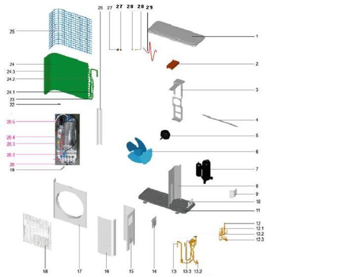
38 Exploded view model: ASE-18AH
39 Spare part list No Description Part Code Note Qty Price Code MODEL: ASE-18AH 1 Top cover assembly Supporter assembly of fan motor Condenser assembly Rear net G Chassis assembly Big handle Water collector Right clapboard assembly Valve plate Partition board assembly Front panel assembly Air outlet grille Asynchronous motor Axial flow fan Left supporter bar Electronic control box assembly Fan motor capacitor Compressor capacitor Wire joint Wire joint,2p Installation plate of electric parts Capacitor clip Pipe temperature sensor assembly Liquid valve assembly Liquid valve One way valve way valve assembly Gas valve way valve Compressor wire assembly Compressor Nut Nut Small handle Clamp of front net The data are subject to change without notice.
40 Exploded view model:ase-24ah
41 Spare part list No Description Part Code Note Qty Price Code MODEL: ASE-24AH 1 Top cover assembly Fan motor fixing foam Supporter assembly of fan motor G Rear net frame Asynchronous motor Axial flow fan Compressor Partition board assembly Water collector Valve plate Chassis assembly Liquid valve assembly Filter One way valve Liquid valve way valve assembly Gas valve way valve Big handle assembly Rear right clapboard assembly Front right clapboard assembly Front panel Air outlet grille Small handle Electronic control box assembly Wire joint Wire joint Compressor capacitor Installation plate of electric parts Fan motor capacitor Clamp of front net Pipe temperature sensor assembly Condenser assembly Fluted pipe assembly Input pipe assembly Condenser assembly Rear net G Left supporter Copper nut Copper nut Sphere pad Sphere pad Compressor wire assembly The data are subject to change without notice.
42 Exploded view model:ase-36ah
43 Spare part list No Description Part Code Note Qty Price Code MODEL: ASE-36AH 1 Top cover assembly Rear supporter G Supporter assembly of fan motor Fix clamp of segregator Accumulator cylinder Asynchronous motor Suction pipe Condenser assembly Rear right clapboard assembly Front right clapboard assembly way valve assembly Gas valve way valve Liquid valve assembly Liquid valve Valve plate Chassis Compressor Discharge pipe assembly Pressure switch Copper nut Copper nut Sphere pad Sphere pad Compressor wire assembly Crankcase electric heater Pipe temperature sensor assembly Discharge temperature sensor Front panel Front net assembly Axial flow fan Partition board assembly Rear net G Left supporter Electronic control box assembly Wire joint Wire joint Wire joint Installation plate of electric parts AC contactor Terminal board Main control board assembly Compressor capacitor Transformer Water collector Big handle assembly Indoor temperature sensor assembly The data are subject to change without notice.
44 Exploded view model:ase-48ah, ASE-60AH (=ASF-60A outdoor unit)
45 Spare part list No Description Part Code Note Qty Price Code MODEL: ASE-48AH 1 Top cover assembly Axial flow fan Rear-left supporting board Asynchronous motor YDK65-6(B) Asynchronous motor YDK65-6F(B) Supporter assembly of fan motor Front net assembly Clamp of front net Front panel Partition board assembly Front-right panel assembly Rear-right panel Rear supporter Indoor temperature sensor assembly Condenser assembly Condenser assembly Pipe temperature sensor assembly Chassis Rear net Separator Big handle assembly Handle Water collector Valve plate Copper nut Copper nut Sphere pad Sphere pad Electronic control box assembly Installation plate of electric parts Main control board assembly AC contactor Transformer Wire joint Wire joint Wire joint Fan motor capacitor Compressor Compressor wire assembly Crankcase electric heater Discharge pipe assembly A Pressure switch Discharge temperature sensor Suction pipe assembly A Pressure switch Liquid valve assembly High pressure valve Gas valve assembly way valve Gas valve Condenser connection pipe The data are subject to change without notice.
46 No Description Part Code Note Qty MODEL: ASE-60AH (=ASF-60A outdoor) 1 Top cover assembly Axial flow fan Rear-left supporting board Asynchronous motor YDK65-6(B) Asynchronous motor YDK65-6F(B) Supporter assembly of fan motor Front net assembly Clamp of front net Front panel Partition board assembly Front-right panel assembly Rear-right panel Rear supporter Indoor temperature sensor assembly Condenser assembly Pipe temperature sensor assembly Chassis Rear net Separator Big handle assembly Handle Water collector Valve plate Copper nut Copper nut Sphere pad Sphere pad Electronic control box assembly Installation plate of electric parts Main control board assembly AC contactor Transformer Wire joint Wire joint Wire joint Fan motor capacitor Compressor Compressor wire assembly Crankcase electric heater Discharge pipe assembly Pressure switch A Discharge temperature sensor Suction pipe assembly Pressure switch Liquid valve assembly Liquid valve Gas valve assembly way valve Gas valve The data are subject to change without notice. Price Code
FAN COIL USER MANUAL TC18C2DWB1 TC24C2DWB1 TC37C2DWB1 TC48C2DWB1 TC60C2DWB Innovair Corporation. All Rights Reserved.
 FAN COIL USER MANUAL TC18C2DWB1 TC24C2DWB1 TC37C2DWB1 TC48C2DWB1 TC60C2DWB1 Duct Type 1. Features...7 2. Dimensions...8 3. Service Space...9 4. Wiring Diagrams...10 5. Capacity Tables...11 6. Capacity
Part 1 General Information... 1 Part 2 Indoor Units... 7 Part 3 Outdoor Units Part 4 Installation Part 5 Control...
 MCAC-UTSM-2008-11 Contents Part 1 General Information... 1 Part 2 Indoor Units... 7 Part 3 Outdoor Units... 88 Part 4 Installation... 127 Part 5 Control... 136 The specifications, designs, and information
Contents. Part 1 General Information...2 Part 2 Outdoor units...7 Part 3 Installation...63 Part 4 Controller...79
 MCAC-TSM-2008-02 Contents Part 1 General Information...2 Part 2 Outdoor units...7 Part 3 Installation...63 Part 4 Controller...79 Contents i MCAC-TSM-2008-02 Introduction Introduction Midea Mini Unitary
MANUAL DE INGENIERIA. Part 1 General Information... 1 Part 2 Indoor Units... 6 Part 3 Outdoor Units... 30
 MANUAL DE INGENIERIA Evaporadora Sopladora 'MVA' con Condensadora 'MOV' - Blue Star Part 1 General Information... 1 Part 2 Indoor Units... 6 Part 3 Outdoor Units... 30 Part 1 General Information 1. Model
Floor-Standing Type(E Series)
") Floor-Standing Type(E Series) Model: MFE-60CE, MFE-60AE Part 1. Product Features With a spiral shape, the computer-aided simulation designed air passage system can efficiently reduce noise. The Soft touch
Floor-Standing Type(E Series) Model: MFE-60CE, MFE-60AE Part 1. Product Features With a spiral shape, the computer-aided simulation designed air passage system can efficiently reduce noise. The Soft touch
Floor-Standing Type(S2 Series)
") Floor-Standing Type(S2 Series) Model: MFS2-24CR(N2), MFS2-24HR(N2), MFS2-24AR(N2), MFS2-48CR(N2), MFS2-48AR(N2) Part 1. Product Features Strong air supply. Wide angle and long distance air supply. Easy
Floor-Standing Type(S2 Series) Model: MFS2-24CR(N2), MFS2-24HR(N2), MFS2-24AR(N2), MFS2-48CR(N2), MFS2-48AR(N2) Part 1. Product Features Strong air supply. Wide angle and long distance air supply. Easy
TECHNICAL & SERVICE MANUAL
 TECHNICAL & SERVICE MANUAL CASSETTE TYPE AIR-CONDITIONER (One-way cassette) FSK-94HF FI-SM-040830 One-way Cassette Air-conditioner Table of Contants Part 1. Product Features 2 Part 2. Specification 3 Part
Ceiling & Floor type Unit
 Ceiling & Floor type Unit Part 1. Product Features Quietest operation, low noise. Thin design, space-saving. Easy to operate, remote control. 16 Part 2. Specification Model MUA-18HRN2 MUA-24HRN2 MUA-24HRN2
SERVICE MANUAL UNI ON/OFF ASC-60A
 SERVICE MANUAL UNI ON/OFF ASC-60A The specifications, designs, and information in this book are subject to change without notice for product improvement. Model Power supply Cooling Heating Indoor fan motor
R410A50Hz Universal Outdoor Series Technical Manual
 Outdoor Unit R410A 50Hz Universal Outdoor Series Technical Manual 2013 Version LCAC/2.0/201308 I GD Chigo Heating & Ventilation Equipment Co., Ltd. Content Content PART 1.General Information... 1 1.Nomenclature...
60Hz R410A ON/OFF CONDENSING UNIT MODEL: MTVCN. Service Manual Contents
 60Hz R410A ON/OFF CONDENSING UNIT MODEL: MTVCN Service Manual 2016 Contents i Refrigerant pipe installation Outdoor unit installation (Top Discharge Unit) 4.1 Location selection Before starting the installation,
Service Manual. Air Conditional
 Air Conditional Service Manual Большая библиотека технической документации http://splitoff.ru/tehn-doc.html каталоги, инструкции, сервисные мануалы, схемы. -2 - MODEL: AC-FR30CM -3 - CONTENTS SPECIFICATION...
Midea R410A Tropical ClimaCreator Series Rooftop Package 220V 3Ph 60Hz Technical Manual
 Midea R410A Tropical ClimaCreator Series Rooftop Package 220V 3Ph 60Hz Technical Manual Midea reserves the right to discontinue, or change specification or designs at any time without notices and without
Service Manual. Air Conditional
 Air Conditional Service Manual Большая библиотека технической документации http://splitoff.ru/tehn-doc.html каталоги, инструкции, сервисные мануалы, схемы. -2 - MODEL: AC-FR30HM -3 - CONTENTS SPECIFICATION...
Part 1 General Information... 1 Part 2 Outdoor Unit... 4 Part 3 Installation... 45
 Contents Part 1 General Information... 1 Part 2 Outdoor Unit... 4 Part 3 Installation... 45 The specifications, designs, and information in this book are subject to change without notice for product improvement.
Cassette SERVICE MANUAL. YKHC 18 to 48 YKHC 18 YKHC 24 YKHC 30 YKHC 36 YKHC 48 SM-YKHC-18-48GB 03-07
 Cassette YKHC 18 to 48 SERVICE MANUAL YKHC 18 YKHC 24 YKHC 30 YKHC 36 YKHC 48 SM-YKHC-18-48GB 03-07 How to read the model? * * * Y K H C 24 F S B A A A Range: F = Floor standing H = High wall M = Master
FOR SLIM DUCT/CEILING TYPE
 INSTALLATION MANUAL AIR CONDITIONER FOR SLIM DUCT/CEILING TYPE For correct installation, read this manual before starting installation. This manual may be subject to change without notice for purpose of
UCV CONDENSING UNITS SPECIFICATIONS 1. Specifications
 UCV CONDENSING UNITS SPECIFICATIONS 1. Specifications Model UCV-76C UCV-96C Code 220075900040 220075900020 Power supply V- Ph-Hz 380-415~3~50 Capacity Btu/h 76000 96000 Cooling Input W 8100 10000 Rated
Technical Manual. R410A 50Hz Universal Outdoor Series Inverter type. R410A50Hz Universal Outdoor Series Technical Manual LCAC/2016.
 Outdoor Unit R410A 50Hz Universal Outdoor Series Inverter type Technical Manual LCAC/2016.1 I GD Chigo Heating & Ventilation Equipment Co., Ltd. Content Part 1. General Information... 1 1. Nomenclature...
Service Manual. Multi Split Type Heat Pump Air Conditioners. Applied to: HS-9U2IM_HOS-18U2IM HS-9U11IM_HS-12U11IM_HOS-21U11IM
 Service Manual Multi Split Type Heat Pump Air Conditioners Applied to: HS-9U2IM_HOS-18U2IM HS-9U11IM_HS-12U11IM_HOS-21U11IM CONTENT 1. Product features 2. Specification 3. Dimensions 4. Refrigeration cycle
Installation, Operation & Maintenance
 Installation, Operation & Maintenance Contura 5G Series R410a High Ambient & High Efficiency MS-SVX041A-EN 1 Contents 1. Precaution 1.1 Safety Precuation 03 1.2 Warning 03 2. Product Specifications 06
[U] Serie MOV. Manual de Ingeniería
![[U] Serie MOV. Manual de Ingeniería](/thumbs/82/86228730.jpg "[U] Serie MOV. Manual de Ingeniería") [U] Serie MOV Uniidades Condensadoras (Fllujjo Verttiicall) 6..3,, 8 y 12..5 Ton Manual de Ingeniería - 112- Outdoor Units_MOV 1. Specifications.... 2. Dimension... 3. Service Space. 4. Piping Diagrams
[U] Serie MOV Uniidades Condensadoras (Fllujjo Verttiicall) 6..3,, 8 y 12..5 Ton Manual de Ingeniería - 112- Outdoor Units_MOV 1. Specifications.... 2. Dimension... 3. Service Space. 4. Piping Diagrams
DC INVERTER MULTI-SYSTEM AIR CONDITIONER
 TECHNICAL & SERVICE MANUAL OUTDOOR UNIT : CLM97 CLM7 CLM7 FILE NO. Destination: North America DC INVERTER MULTI-SYSTEM AIR CONDITIONER Capacity at 0V 9,700 BTU/h,00 BTU/h 0,600 BTU/h Outdoor Model No.
Service manual. MIV V4+ Mini
 DM12-01.01.05en Service manual MIV V4+ Mini DC INVERTER R410A (~220V, 50Hz, 1Ph) MVUH80A-VA1 Contents Part 1 General Information... 1 Part 2 Outdoor Units... 6 Part 3 Installation... 44 DM12-01.01.05en
Technical Support Division GD CHIGO HEATING & VENTILATION EQUIPMENT CO., LTD.
 Technical Support Division 2017-4-25 New CMV System - Floor ceiling Indoor Unit 1 1. External appearance 2. Nomenclature 3. Specifications 4. Dimensions 5. Service space 6. Piping diagram 7. Wiring diagram
Room Air Conditioner Service and Parts Manual
 Cool Dry Temp Mode Room Air Conditioner Service and Parts Manual F Fan Speed hr Timer 0n 0ff Money Saver Fan Only Auto Swing Power CP06 CP08 93011401_01 CONTENTS 1. PREFACE 1.1 SAFETY PRECAUTIONS...2 1.2
Content. The specifications, designs, and information in this book are subject to change without notice for product improvement.
 MCAC-ATSM-2014-01 Content R410A Mini Split Chiller 50Hz 1. Model Names of Outdoor Units... 2 2. External Appearance... 2 3. menclature... 3 4. Features... 4 5. Descriptions of Standard Unit... 6 6. Specifications...
High static Pressure Duct Type Air-conditioner
 High static Pressure Duct Type Air-conditioner Part 1. Product Features In case the ceiling is super-high. Blowing pressure of Indoor Unit can reach 196Pa. The air conditioner delivers cold wind to every
Service Manual & Installation Manual
 GE Consumer & Industrial Appliances Service Manual & Installation Manual Split System Air Conditioner Model numbers: GE AIR C18 GE AIR C24 GE AIR C34 GE AIR C41 1 Introduction and Features Model Remarks
MINI CHILLER INVERTER H4 Service manual MUENR-H4 (5, 7, 10, 12, 14, 16 kw)
") MINI CHILLER INVERTER H4 Service manual MUENR-H4 (5, 7, 10, 12, 14, 16 kw) CL25610 to CL25615 English Content 1. Outdoor units lineup... 2 2. Nomenclature... 3 3.Features... 4 4. Description of main components...
MINI CHILLER INVERTER H4 Service manual MUENR-H4 (5, 7, 10, 12, 14, 16 kw) CL25610 to CL25615 English Content 1. Outdoor units lineup... 2 2. Nomenclature... 3 3.Features... 4 4. Description of main components...
Window Y9USC/E 09 / 12 / 18 B5R
 Window Y9USC/E 09 / 12 / 18 B5R SERVICE MANUAL Y9USC-09 B5R; Y9USE-09 B5R Y9USC-12 B5R; Y9USE-12 B5R Y9USC-18 B5R; Y9USE-18 B5R SM-Y9USC-E-09-18GB 03-07 1. Precaution... 2 1.1 safety Precaution... 2 1.2
Four-way Cassette Type
 Four-way Cassette Type Part 1. Product Features 1) Low operation noise ---Streamline plate ensures quietness ---Creates natural and comfortable environment 2) Efficient cooling ---Equal, fast and wide
Installation and Operation Manual. CMA12SB-0 Series. Horizontal/Side Discharge Condensing Units
 Installation and Operation Manual CMA12SB-0 Series Horizontal/Side Discharge Condensing Units 517.787.2100 www.marsdelivers.com www.heatcontroller.com Heat Controller CONTENTS PAGE 1. PRES... 1 2. INSTALLATION
Multi Splits Series. DKH Indoor Units DBC Indoor Units DAQ Indoor Units DCD Indoor Units Outdoor Units JOSI-DKH009-N11
 Multi Splits Series DKH Indoor Units DBC Indoor Units DAQ Indoor Units DCD Indoor Units Outdoor Units JOSI-DKH009-N11 JOAU-ZCY218-H11 JOSI-DKH012-N11 JOSI-DBC012-N11 JOSI-DAQ012-N11 JOSI-DCD012-N11 JOAU-ZCY327-H11
Blanc ON-OFF Series. Service Manual 2016
 Blanc ON-OFF Series Service Manual 2016 MSMA1A-07HRN1 / MOAB02-07HN1 MSMA1A-09HRN1 / MOAB02-09HN1 MSMA1B-12HRN1 / MOBA01-12HN1 MSMA1C-18HRN1 / MOBA03-18HN1 MSMA1D-24HRN1 / MOCA02-24HN1 1 Blanc On-off DM16-01.01.07en
AIR HANDLER UNIT R410A 60HZ ON-OFF CONTROL
 TM_AHU_60R410A_ONOFF_T_SA_NA_171205 AIR HANDLER UNIT R410A 60HZ ON-OFF CONTROL 2017 TECHNICAL MANUAL Table of Contents Page 1. Specifications... 4 1. Model Reference 2. General Specifications 3. Dimensional
R410A50Hz Universal Outdoor Series Technical Manual
 Outdoor Unit R410A 50Hz Universal Outdoor Series Service Manual 2012 Version I GD Chigo Heating & Ventilation Equipment Co., Ltd. Content Content PART 1.General Information... 1 1.Nomenclature... 2 2.Model
Cover. Service Manual PAC9037 PAC12037 PAC13037 PAC18037
 Cover Service Manual PAC9037 PAC12037 PAC13037 PAC18037 Content Content 1. Precaution 2 1.1 Safety Precaution 2 1.2 Warning 2 2. Function 4 3. Dimension 6 3.1 Indoor unit 6 3.2 Outdoor unit 6 4. Refrigerant
MODEL: CCT 301 INV CCT 501 INV CCT 70 INV-S CCT 100 INV-S CCT 140 INV-S CCT 170 INV-S
 MODEL: CCT 301 INV CCT 501 INV CCT 70 INV-S CCT 100 INV-S CCT 140 INV-S CCT 170 INV-S Compact Four-way Cassette Type 1. Features... 2. Specification... 3. Dimension... 4. Service Space... 5. Wiring Diagram...
DC INVERTER MULTI-SYSTEM AIR CONDITIONER
 TECHNICAL & SERVICE MANUAL OUTDOOR UNIT : CU-3KE19NBU CU-4KE24NBU CU-4KE31NBU DC INVERTER MULTI-SYSTEM AIR CONDITIONER Capacity at 0V 19,100 BTU/h,200 BTU/h 30,600 BTU/h Outdoor Model No. CU-3KE19NBU CU-4KE24NBU
[U] Serie MHB / MHA Manual de Ingeniería
![[U] Serie MHB / MHA Manual de Ingeniería](/thumbs/86/93369605.jpg "[U] Serie MHB / MHA Manual de Ingeniería") [U] Serie MHB / MHA Evaporadoras Soplladoras de Alltta Presiión Esttáttiica 6..3,, 8 y 12..5 Ton Manual de Ingeniería. - 1 - General Information_MHB 1. Model Names of Indoor/Outdoor Units 2. External Appearance
[U] Serie MHB / MHA Evaporadoras Soplladoras de Alltta Presiión Esttáttiica 6..3,, 8 y 12..5 Ton Manual de Ingeniería. - 1 - General Information_MHB 1. Model Names of Indoor/Outdoor Units 2. External Appearance
TECHNICAL DATA & SERVICE MANUAL
 TECHNICAL DATA & SERVICE MANUAL OUTDOOR UNIT: GRF188R5TAA GRF228R5TAA GRF228R7TAA SPLIT SYSTEM AIR CONDITIONER Model No. Product Code No. GRF188R5TAA 38.7107.083 GRF228R5TAA 38.7107.084 GRF228R7TAA 38.7107.085
R22 air-cooled modular chiller 50Hz unit. Content
 Content 1.Nomenclature... 2 2.Product Schedule... 2. External Appearance... 4.Features... 4 5.Specification... 6 6.Dimension... 10 7.Refrigeration System Sketch Drawing... 14 8.Wiring Diagrams... 16 9.Electric
MVD. Cassette 4 Ways FCU DC Service manual MUCS-W7. CL04417 to CL04419 English.
 MVD Cassette 4 Ways FCU DC Service manual MUCS-W7 www.mundoclima.com CL04417 to CL04419 English 4-way cassette 1. External Appearance... 2 2. Features... 2 3. Product lineup... 3 4. Accessories... 4 5.
AIR CONDITIONER CASSETTE
 Installation manual AIR CONDITIONER CASSETTE English 10. REFRIGERANT TUBING...17 11. PANEL INSTALLING...19 12. FINAL TASKS...21 1 1. REQUIRED TOOLS FOR INSTALLATION WORK 2. SAFETY PRECAUTIONS Installation
Technical Manual. R410A 50Hz Universal Outdoor Series Inverter type Version. R410A50Hz Universal Outdoor Series Technical Manual LCAC/1.
 Outdoor Unit R410A 50Hz Universal Outdoor Series Inverter type Technical Manual 2014 Version LCAC/1.0/201401 I GD Chigo Heating & Ventilation Equipment Co., Ltd. Content PART 1.General Information... 1
INVERTER SPLIT - TYPE
 INVERTER SPLIT - TYPE ISSUE No 2 DATE 04/09/08 P/No 2020323A2868 CONTENTS SAFETY PRECAUTIONS Warning 2 Operating temperature 2 BEFORE INSTALLATION Tools needed for installation 3 Items required for installing
Klimaire 16 SEER CENTRAL DUCTED YEAR. Central Air Conditioning & Heat Pump Systems Multi Position Air Handling Units LIMITED GUARANTEE
 Klimaire 16 SEER CENTRAL DUCTED Central Air Conditioning & Heat Pump Systems Multi Position Air Handling Units 10 YEAR LIMITED GUARANTEE R410A R E F R I G E R A N T CSM Condensing Units Features Condensing
TABLE OF CONTENTS. NOTE: Read the entire instruction manual before starting the installation. TROUBLESHOOTING... 13
 R 410A Duct Free Split System Air Conditioner and Heat Pump Product Family: DFS4(A/H) System, DFC4(A/H)3 Outdoor, DFF4(A/H)H Indoor NOTE: Read the entire instruction manual before starting the installation.
TECHNICAL DATA & SERVICE MANUAL
 TECHNICAL DATA & SERVICE MANUAL OUTDOOR UNIT: AE726SCL AE752SCL AE71SCL3 AE735SCL AE752SCL3 AE100SCL3 AE764SCL3 AE125SCL3 SPLIT SYSTEM AIR CONDITIONER Model No. AE726SCL AE735SCL AE752SCL AE752SCL3 AE764SCL3
INSTALLATION INSTRUCTIONS
 INSTALLATION INSTRUCTIONS - Wall-mount indoor unit - OPERATING LIMITS Cooling Maximum conditions Heating Maximum conditions Outdoor temperature : 122 F (50 C) D.B. Outdoor temperature : 75 F (24 C) D.B.
Content. Part 1 General Information Part 2 Indoor Units Part 3 Outdoor Units Part 4 Installation Part 5 Control...
 R410A Tropical Split Type AC Technical Manual Content Content Part 1 General Information... 2 Part 2 Indoor Units... 6 Part 3 Outdoor Units... 88 Part 4 Installation... 120 Part 5 Control... 154 Indoor
Condensing Unit Service Manual (T1/R410a/60Hz)
") GREE COMMERCIAL AIR CONDITION DUCT TYPE SPLIT AIR CONDITIONER Condensing Unit Service Manual (T/R40a/60Hz) GREE ELECTRIC APPLIANCES INC. OF ZHUHAI CONTENTS PRODUCT... 2 MODELS LIST... 2 2 NOMENCLATURE...
GREE COMMERCIAL AIR CONDITION DUCT TYPE SPLIT AIR CONDITIONER Condensing Unit Service Manual (T/R40a/60Hz) GREE ELECTRIC APPLIANCES INC. OF ZHUHAI CONTENTS PRODUCT... 2 MODELS LIST... 2 2 NOMENCLATURE...
INSTALLATION MANUAL. Split-type Air Conditioner (Cooling and Heating) Outdoor Unit UQB09JJWC UQB12JJWC. Indoor Unit AQB09JJWC AQB12JJWC
 Outdoor Unit UQB09JJWC UQB12JJWC. Indoor Unit AQB09JJWC AQB12JJWC") AQB09JJ6WC_IM_E_2585 2006.4.17 4:26 PM Page 17 INSTALLATION MANUAL Indoor Unit AQB09JJWC AQB12JJWC Outdoor Unit UQB09JJWC UQB12JJWC ENGLISH FRANÇAIS ESPAÑOL Split-type Air Conditioner (Cooling and Heating)
AQB09JJ6WC_IM_E_2585 2006.4.17 4:26 PM Page 17 INSTALLATION MANUAL Indoor Unit AQB09JJWC AQB12JJWC Outdoor Unit UQB09JJWC UQB12JJWC ENGLISH FRANÇAIS ESPAÑOL Split-type Air Conditioner (Cooling and Heating)
YC ON-OFF SERIES. Service Manual
 YC ON-OFF SERIES Service Manual CONTENTS 1. Precaution... 3 1.1 Safety Precaution... 3 1.2 Warning... 3 2. Model Lists... 6 3. Dimension... 7 3.1 Indoor Unit... 7 3.2 Outdoor Unit... 11 4. Refrigerant
TECHNICAL DATA & SERVICE MANUAL SPLIT SYSTEM AIR CONDITIONER OUTDOOR UNIT: AE22AC/ACL/AH AE28AC/ACL/AH AE38AC/ACL/AH AE42AC/ACL/AH
 TECHNICAL DATA & SERVICE MANUAL OUTDOOR UNIT: AE22AC/ACL/AH AE28AC/ACL/AH AE38AC/ACL/AH AE42AC/ACL/AH SPLIT SYSTEM AIR CONDITIONER Model No. Product Code No. AE22AH 387031006 AE28AH 387031007 AE38AH 387031008
Multi Inverter Air Conditioning Condensing Units - Summary
 Multi Inverter Air Conditioning Condensing Units - Summary Model Description Nominal Max of Cooling Inverter No. Heating of (kw) Fan Condensing (kw) Coils Unit ECO18MS2 Twin Multi Inverter 5kW 5.2 6.1
Aqua Mini Full DC Inverter Unitary Chiller 50Hz. Content
 MCAC-ATSM-2014-09 Content 1. Outdoor units lineup... 2 2. Nomenclature... 3 3.Features... 4 4. Description of main components... 8 5. Specifications... 10 6. Dimensions... 14 7. Piping Diagram... 15 8.
Service Manual & Installation Manual
 GE Consumer & Industrial Appliances Service Manual & Installation Manual Split System Air Conditioner Model numbers: GE AIR F24 GE AIR F34 GE AIR F41 1 2 3 Introduction and Features Model Remarks GE AIR
INSTALLATION MANUAL. Split-type Air Conditioner (Cooling and Heating) Indoor Unit AQB18J6WC AQB24J2WC. Outdoor Unit UQB18J6WC UQB24J2WC
 Indoor Unit AQB18J6WC AQB24J2WC. Outdoor Unit UQB18J6WC UQB24J2WC") AQB8J6WC_IM_E_25864 2006.4.4 3:29 PM Page 7 INSTALLATION MANUAL Indoor Unit AQB8J6WC AQB24J2WC Outdoor Unit UQB8J6WC UQB24J2WC ENGLISH FRANÇAIS ESPAÑOL Split-type Air Conditioner (Cooling and Heating)
AQB8J6WC_IM_E_25864 2006.4.4 3:29 PM Page 7 INSTALLATION MANUAL Indoor Unit AQB8J6WC AQB24J2WC Outdoor Unit UQB8J6WC UQB24J2WC ENGLISH FRANÇAIS ESPAÑOL Split-type Air Conditioner (Cooling and Heating)
Installation Instructions
 38MHR Outdoor Unit Single Zone Ductless System Sizes 09 to 24 Installation Instructions NOTE: Read the entire instruction manual before starting the installation. NOTE: Images are for illustration purposes
Choosing the installation site. Installation. 07 Choosing the installation site
 Installation Installation warnings: 1. Carefully read the installation manual before beginning. 2. Follow each step as shown. 3. Observe all local, state, and national electrical codes and by qualified,
Installer manual AG-AA10. Air/air heat pump IHB GB AG-AA10-30 AG-AA10-40/50
 -30 Installer manual Air/air heat pump -40/50 IHB GB 1516-1 331554 Table of Contents 1 Important information 2 5 Installation 7 Safety information 2 Model combinations 7 Read before starting the installation
Introduction Part 1 : General Information Part 2: Indoor Units Part 3: Installation Part 4: Control
 Introduction Part 1 : General Information Part 2: Indoor Units Part 3: Installation Part 4: Control i Introduction Fan coil unit is a kind of compound device which assemble fan and surface-type coil heating-exchanger
Room Air Conditioner CP06 & CP08. Chill 115 Volts. Service & Parts Manual THE EXPERTS IN ROOM AIR CONDITIONING _02
 Room Air Conditioner Service & Parts Manual 2014-2015 CP06 & CP08 Chill 115 Volts THE EXPERTS IN ROOM AIR CONDITIONING 93011401_02 CONTENTS 1. PREFACE 1.1 SAFETY PRECAUTIONS...2 1.2 INSULATION RESISTANCE
Miraco MISR REFRIGERATION & AIR CONDITIONING MFG. CO.
 Miraco MISR REFRIGERATION & AIR CONDITIONING MFG. CO. High Efficiency Green Slim Line Ceiling Concealed Ducted Split Systems Cool Only Rev. August 2015 12K - 18K - 24K - 30K - 36K - 42K - 48K - 60K IAQ
Service Manual. Room Air Conditioner Split Wall-Mounted Type. Applies to: HSG-09HRN1 HSG-12HRN1 HSG-18HRN1 HSG-24HRN1
 Service Manual Room Air Conditioner Split Wall-Mounted Type Applies to: HSG-09CRN1 HSG-12CRN1 HSG-18CRN1 HSG-24CRN1 HSG-09HRN1 HSG-12HRN1 HSG-18HRN1 HSG-24HRN1 NOTE: Please read this first before servicing
TECHNICAL & SERVICE MANUAL WINDOW TYPE AIR CONDITIONER SA 123A FILE NO. SA 123A REFERENCE NO. SM700513
 TECHNICAL & SERVICE MANUAL SA 123A FILE NO. WINDOW TYPE AIR CONDITIONER Model No. Product Code No. Destination SA-123A 1 851 006 95 Australia SA 123A REFERENCE NO. SM700513 IMPORTANT! Please Read Before
Amendment Sheet. Nomenclature M 5 AC V 100 C R - F X AA. Code : M5ACV Date : Superceded : M5ACV
 Amendment Sheet Code : M5ACV-2005-0002 Date : 08-05-2006 Superceded : M5ACV-2005-0001 Nomenclature Production spec variation Type of ref. connection X : Not applicable Electrical A : 220-240V/1Ph/50Hz
SERVICE MANUAL SPLIT WALL-MOUNTED TYPE MODELS MWCOHC30S/MRCOHC30AS MWCOHC36S/MRCOHC36AS
 SERVICE MANUAL SPLIT WALL-MOUNTED TYPE MODELS MWCOHC30S/MRCOHC30AS MWCOHC36S/MRCOHC36AS CONTENTS 1. Precaution... 1 1.1 Safety Precaution... 1 1.2 Warning... 1 2. Function... 6 3. Dimension... 7 3.1 Indoor
Midea Precision Air Conditioner Technical Manual (Down delivery series)
") Midea Precision AC Technical Manual-Down Delivery Series MCAC-RTSM-2013-04 Midea Precision Air Conditioner Technical Manual (Down delivery series) Midea reserves the right to discontinue, or change specification
Midea Precision AC Technical Manual-Down Delivery Series MCAC-RTSM-2013-04 Midea Precision Air Conditioner Technical Manual (Down delivery series) Midea reserves the right to discontinue, or change specification
TECHNICAL & SERVICE MANUAL WINDOW TYPE AIR CONDITIONER SA 183A FILE NO. SA 183A REFERENCE NO. SM Destination Australia SA-183A
 TECHNICAL & SERVICE MANUAL SA 183A FILE NO. WINDOW TYPE AIR CONDITIONER Model No. Product Code No. SA-183A 1 851 006 96 Destination Australia SA 183A REFERENCE NO. SM700514 IMPORTANT! Please Read Before
Horizontal Water Source Heat Pumps And Cooling Only Unit
 MWH-B-2005 Horizontal Water Source Heat Pumps And Cooling Only Unit Models: MWH MWH MWH MWH MWH 011 B/BR MWH 012 B/BR MWH 015 B/BR MWH 020 B/BR MWH 025 B/BR MWH 030 B/BR 040 B/BR 050 B/BR 060 B/BR 070
Installation Instructions
 8GXM / 0GXM Multi---Split High---Wall Duct Free Split System 8GXM --- Size 18k, k, and 0k 0GXM --- Size 9k, 1k, and 18k Installation Instructions NOTE: Read the entire instruction manual before starting
Air Conditioner Service Manual
 Air Conditioner Service Manual Большая библиотека технической документации http://splitoff.ru/tehn-doc.html каталоги, инструкции, сервисные мануалы, схемы. 2 MODEL: AC-S13CEGL1 3 CONTENTS TECHNICAL SPECIFICATION...
Outdoor Unit:CPP018CD(O) CPP024CD(O) CPP036CD(O)-DU CPP048CD(O)-DU
 CPP024CD(O) CPP036CD(O)-DU CPP048CD(O)-DU") Indoor Unit:FPA-18 FPA-24 FPA-36DU FPA-48DU Outdoor Unit:CPP018CD(O) CPP024CD(O) CPP036CD(O)-DU CPP048CD(O)-DU If used as MULTI unit, please refer to the Installation & operation manuals packed with outdoor
Indoor Unit:FPA-18 FPA-24 FPA-36DU FPA-48DU Outdoor Unit:CPP018CD(O) CPP024CD(O) CPP036CD(O)-DU CPP048CD(O)-DU If used as MULTI unit, please refer to the Installation & operation manuals packed with outdoor
Mini unitary chiller. Mini unitary chiller
 Mini unitary chiller Mini unitary chiller Product description Features and benefits Description of main components Specification Operation limits Hydraulic performance Dimension Service space Piping diagram
HEAT PUMP INSTALLATION MANUAL
 DUCTLESS INVERTER HEAT PUMP INSTALLATION MANUAL Models: TERRA09HP230V1A TERRA12HP230V1A TERRA18HP230V1B TERRA24HP230V1B Thank you for choosing a Gree Terra Ductless Heat Pump for your customer. Please
TWO-PIPE CASSETTE FAN COIL UNIT SERVICE MANUAL. SF-xxxC2 AIR CONDITIONING
 TWO-PIPE CASSETTE FAN COIL UNIT SERVICE MANUAL SF-xxxC2 AIR CONDITIONING Compact 4-way cassette FCU 1. External Appearance... 2 2. Features... 2 3. Product lineup... 3 4. Accessories... 3 5. Specifications...
Room Air Conditioner SERVICE MANUAL MODEL : LW6013ERY3. CAUTION
 www.zenithappliances.com Room Air Conditioner SERVICE MANUAL MODEL : LW6013ERY3 CAUTION BEFORE SERVICING THE UNIT, READ THE SAFETY PRECAUTIONS IN THIS MANUAL. ONLY FOR AUTHORIZED SERVICE PERSONNEL. CONTENTS
1. Features Specification Dimensions Refrigeration cycle diagram Operation limits
 GLORY (ECO) STAR SERIES 1. Features 60 2. Specification 61 61 3. Dimensions 67 67 4. Refrigeration cycle diagram 70 70 5. Operation limits 71 6. Wiring diagram 72 7. Troubleshooting 80 8. Electronic function
13-1. Temperature Regulator
 -1 Step 0 Type/Structure/Features Please refer to this for type, structure and features of. Step 1 Selection Please look at the ID chart to choose the right products depending on the intended uses. Details
DC INVERTER SPLIT SYSTEM AIR CONDITIONER
 AIR CONDITIONER TECHNICAL & SERVICE MANUAL KS1872 + C1872 + CL1872 KS2472 + C2472 + CL2472 FILE NO. Destination: North America DC INVERTER SPLIT SYSTEM AIR CONDITIONER Indoor Model No. KS1872 KS2472 Product
AUTO COOL DRY FAN SPEED AIR SWING OFF ON TIMER TIMER OFF/ON FAN SPEED MODE TEMP AIR SWING TIMER ON SET OFF CANCEL AC RC SET CHECK CLOCK RESET
 AUTO COOL DRY MODE TIMER ON OFF TIMER OFF/ON TEMP ON TIMER FAN SPEED AIR SWING SET 1 2 3 FAN SPEED AIR SWING OFF CANCEL AC RC SET CHECK CLOCK RESET Order No: PAPAMY1611008CE Indoor Unit CS-MPS9SKH CS-MPS12SKH
INSTALLATION INSTRUCTIONS R 410A
 R 410A Ductless Split System Air Conditioner and Heat Pump MODELS: DLC4(A/H) Outdoor, DLF4(A/H) SIZES: 9K, 12K, 18K, 24K, 30K, and 36K NOTE: Read the entire instruction manual before starting the installation.
DLCLRA. INSTALLATION INSTRUCTIONS Outdoor Unit Single Zone Ductless System Sizes 36 to 58 TABLE OF CONTENTS
 DLCLRA INSTALLATION INSTRUCTIONS Outdoor Unit Single Zone Ductless System Sizes 36 to 58 Fig. 1 - Size 36 TABLE OF CONTENTS PAGE SAFETY CONSIDERATIONS... 2 PARTS LIST... 3 SYSTEM REQUIREMENTS... 4 WIRING...
F SERIES ON-OFF SERIES. Service Manual 2016
 F SERIES ON-OFF SERIES Service Manual 2016 CONTENTS 1. Precaution... 3 1.1 Safety Precaution... 3 1.2 Warning... 3 2. Function... 6 3. Dimension... 7 3.1 Indoor Unit... 7 3.2 Outdoor Unit... 9 4. Refrigerant
TECHNICAL & SERVICE MANUAL WINDOW TYPE AIR CONDITIONER SA 128S5 FILE NO. SA 128S5 REFERENCE NO. SM700338
 TECHNICAL & SERVICE MANUAL SA 128S5 FILE NO. WINDOW TYPE AIR CONDITIONER Model No. Product Code No. Destination SA-128S5-A 1 851 004 09 General (50Hz) & Europe SA 128S5 REFERENCE NO. SM700338 IMPORTANT!
Split-type Air-Conditioner INSTALLATION MANUAL CONTENTS FOR INSTALLER MXZ-3B54VA MXZ-4B71VA. English
 Split-type Air-Conditioner MXZ-3B54VA MXZ-4B71VA INSTALLATION MANUAL English Refer to the installation manual of each indoor unit for indoor unit installation. IMPORTANT NOTES TO COMPLY WITH THE REQUIREMENTS
Midea R410A Domestic Pools & Spas Heat Pump Water Heater 50Hz A1 Series Technical Manual
 Midea R410A Domestic Pools & Spas HPWH 50Hz Technical Manual MCAC-HTSM-201409 Midea R410A Domestic Pools & Spas Heat Pump Water Heater 50Hz A1 Series Technical Manual Applicable Model: (New CE safety directive)
INSTALLATION MANUAL COMFORT...BUILT TO LAST. 9,000, 12,000 and 18,000 BTU SINGLE-ZONE DUCTLESS MINI-SPLIT SYSTEM Heat Pump
 COMFORT...BUILT TO LAST 9,000, 12,000 and 18,000 BTU SINGLE-ZONE DUCTLESS MINI-SPLIT SYSTEM Heat Pump INSTALLATION MANUAL INDOOR UNIT: 1PAMSH09-SZW-14.5 1PAMSH09-SZW-15 1PAMSH12-SZW-15 1PAMSH18-SZW-15
DC Inverter Multi-split System Technical Manual - 50Hz/R410a
 DC Inverter Multi-split System Technical Manual - 50Hz/R410a A/1/LCAC/2/TM/1.0/201111 Content Contents Part 1. General Information... 1 1. Features... 1 2. Nomenclature... 3 3. Products Line-up... 5 4.
Wall Mounted Split Systems
 MWM - 2005 Wall Mounted Split Systems Models: MWM 007F/FR MWM 010F/FR MWM 015F/FR MWM 020F/FR MWM 025F/FR MWM 030F/FR Contents Features... 1 Nomenclature... 2 Specifications... 3 Performance Table... 11
Product Data. Features/Benefits. 30RQ Air-cooled Modular Chiller R22 & R410A & R407C
 Product Data 30RQ Air-cooled Modular Chiller R22 & R410A & R407C Introduction Air-cooled modular chiller is a kind of central airconditioning unit which adopts air as the cooling (or heating) source and
0RGHOV,QGRRU 8QLW MWM36Y3J 2XWGRRU 8QLW MRM36Y3J 11
 MWM36Y3J MRM36Y3J 11 Content Operation Notices Precautions...1 Parts name...2 Screen Operation Guide Buttons on remote controller...3 Introduction for icons on display screen...3 Introduction for buttons
SINGLE - ZONE Ductless Split System Heat Pumps Installation, Operation & Maintenance Manual
 Presents SINGLE - ZONE Ductless Split System Heat Pumps Installation, Operation & Maintenance Manual 9k,12k 18k 24k, 30k, 36k ECR International, Inc. 2201 Dwyer Avenue, Utica NY 13501 Phone: 800.325.5479
ALICE HIGH-WALL DUCTLESS AIR CONDITIONING & HEATING SYSTEM INSTALLATION MANUAL
 ALICE HIGH-WALL DUCTLESS AIR CONDITIONING & HEATING SYSTEM INSTALLATION MANUAL Models: GWH09QC-A3DNA1D (115V) GWH12QC-A3DNA1D (115V) GWH09QC-D3DNA1D (230V) GWH12QC-D3DNA1D (230V) GWH18QD-D3DNA1G (230V)
INSTALLATION MANUAL YDEFS-056C15B YDEFS-071C15B YDEFS-080C15B YDCFS-036C15B YDCFS-080C15B YDCFS-045C15B
 E N GLIS H E-II-YDEFS-YDCFS- INSTALLATION MANUAL FLOOR STANDING TYPE INDOOR UNIT Exposed models: YDEFS-CB YDEFS-CB YDEFS-CB YDEFS-CB YDEFS-CB YDEFS-CB YDEFS-CB Concealed models: YDCFS-CB YDCFS-CB YDCFS-CB
Service Manual. Models WAH48115MB WAH412230MB WH48YMB WH412ZMB
 Service Manual Models WAH48115MB WAH412230MB WH48YMB WH412ZMB TABLE OF CONTENT SPECIFICATION... 2 OUTLINE AND INSTALLATION DIMENSION... 4 REFRIGERATION SYSTEM DIAGRAM... 5 WIRING SCHEMATIC... 6 CONTROLS
SERVICE MANUAL OUTDOOR UNIT. No. OBH530. Models MU-GE50VB- E1 MUH-GE50VB- E1 HFC SPLIT-TYPE AIR CONDITIONERS R410A
 SPLIT-TYPE AIR CONDITIONERS OUTDOOR UNIT SERVICE MANUAL HFC utilized R410A. OBH530 Models MU-GE50VB- E1 - E1 Indoor unit service manual MS/MSH-GE VB Series (OBH529) CONTENTS 1. TECHNICAL CHANGES 2 2. PART