Content. The specifications, designs, and information in this book are subject to change without notice for product improvement.
|
|
|
- Alyson Bishop
- 5 years ago
- Views:
Transcription
1 MCAC-ATSM Content R410A Mini Split Chiller 50Hz 1. Model Names of Outdoor Units External Appearance menclature Features Descriptions of Standard Unit Specifications Dimensions Service Space Piping Diagram Wiring Diagrams Electric Characteristics Capacity Tables Operation Limits Hydraulic Performance Sound Levels Exploded Views Troubleshooting Installation Maintenance Controller The specifications, designs, and information in this book are subject to change without notice for product improvement. 1
 Heat exchanger Compressor type A/C mode Water")


2 R410A Mini Split Chiller 50Hz MCAC-ATSM Model Names of Outdoor Units Model Refrigerant Capacity (kw) Heat exchanger Compressor type A/C mode Water pump box Power Supply (V-Ph-Hz) MGA-D10/N1 R410A 10.5 Plate type Digital scroll Heat pump CE-SBX/N , 1, 50 MGA-D12/N1 R410A 12 Plate type Digital scroll Heat pump CE-SBX/N1-01A , 1, 50 MGA-D14/SN1 R410A 14 Plate type Digital scroll Heat pump CE-SBX/SN , 3, 50 MGA-D16/SN1 R410A 15 Plate type Digital scroll Heat pump CE-SBX/SN1-01A , 3, External Appearance 2.1 Outdoor unit lineups MGA-D10/N1 MGA-D12/N1, MGA-D14/SN1, MGA-D16/SN1 2.2 Water pump box 2
3 MCAC-ATSM R410A Mini Split Chiller 50Hz 3. menclature M G A- D 14 / S N1 Refrigerant N1: R410A Power supply S: V,50Hz,3Ph -: V,50Hz,1Ph Capacity(14kW) Compressor type D: Digital scroll compressor F: Fixed scroll compressor Product series code A: Split chiller C: Unitary chiller Light commercial chiller system Midea 3


4 R410A Mini Split Chiller 50Hz MCAC-ATSM Features 4.1 R410A environment friendly refrigerant, no harm to ozone layer. harm to ozone leyer Greenhouse effect is small 4.2 Easy for installation Air-cooled system, no need cooling water tower, packaged design, easy for installation. 4.3 Energy saving and high reliability a. By adopting Copeland digital scroll compressor, the capacity can be stepless adjusted and the chiller can bring you more comfortable living conditions with less energy consumption. The system has no EMC problem. b. By adopting high efficiency plate heat exchanger, the energy consumption can be reduced. 4


 The setting and operation order can be send to the main board and the running condition can be displayed by the wired")

5 MCAC-ATSM R410A Mini Split Chiller 50Hz c. Metallic protective cabinet with rustproof plyester paint. d. Built-in with voltage protection, current protection, anti-freezing protection, differential water flow protection,compressor,water pump and fan motor overload protection and etc., effectively guarantee the system to work safety. Compressor current protection Phase protection signal output 4.4 Convenient and simple installation With international popular split design, the pump box can be installed inside the matched room and its outdoor unit is compact and light. Expansion tank Plate heat exchanger Water pump Water flow switch 4.5 Wired controller KJRM-120D/BMK-E(Standard) The setting and operation order can be send to the main board and the running condition can be displayed by the wired controller. It can connect max. 16PCBs. It is available for all Midea air cooled scroll chillers. The MODBUS gateway can be customized, it is available by communication port X,Y and E in wired controller. Item Description Item Description 1 Operation icon 9 Water temperature 2 Mode area 10 On/Off key 3 Setting temperature 11 Right, left right key 4 Timing On/Off 12 OK key 5 Function icon 13 Setting key 6 On-line unit Qty. indication 14 Add, reduce key 7 Reserved 15 Cancel key 8 Clock 16 Reserved key 5
6 R410A Mini Split Chiller 50Hz MCAC-ATSM Descriptions of Standard Unit The air cooled reverse-cycle chillers with axial-flow fans operate with refrigerant fluid and are suitable for outdoor installation. They are factory tested and site installation is limited to water and electrical connections. Structure Panels and base are made from galvanized steel plate painted with epoxy powder to ensure total resistance to atmospheric agents. Condensate collection pan as standard. Compressor Midea mini split chillers are equipped with Copeland brand high efficiency, reliable and silence digital scroll compressor, the capacity can be stepless adjusted, the chiller can bring you more comfortable living condition with less energy consumption. The system has no EMC problem. Air cooled condenser Coils The coils are made from high performance and seamless copper tuber and high surface area aluminum fins to ensure optimum heat exchange capability. Condenser coil protection grill is standard. Low noise fan and fan motor To achieve high efficiency heat exchange, the units are equipped with the high performance axial-flow fans. The fan is directly driven by weather proof motor to ensure reliable operation, the fan motor is six pole electric motor with built-in thermal cut-out. Evaporator(in the water pump box) The heat exchanger is made of AISI 316 stainless steel to ensure high heat exchange efficiency, complete with electric heater and differential pressure switch. The complete heat exchanger is insulated with thermal insulation closed cell rubber foam to give optimum thermal insulation. Water pump box The mini split chillers water pump box are fully integrated and equipped with key hydraulic components such as expansion tank, water flow switch, plate type heat-exchanger, water circulating pump. Refrigerant circuit The refrigerant circuit is factory brazed and evacuated before accurately charged with R410A to ensure optimum operating requirement. To ensure flawless continuous operation, each refrigerant circuit is equipped with a carefully sized capillary tube. Power and control electrical panel Power and control electrical panel constructed in accordance with IEC 204-1/EN ,complete with compressor contactor, control via HSW7 control panel. Emergency stop pushbuttons: In case system crisis is occur (e.g: Compressor out of control ), press the emergency stop pushbuttons at once, and turn it clockwise, until crisis is removed. Optional accessories: - Removable metal mesh filter. - Remote keyboard kit. The above accessories are optional. Consult the relative documentation for assembly instructions and technical data. 6

7 MCAC-ATSM R410A Mini Split Chiller 50Hz Outdoor unit MGA-D10/N1 MGA-D12/N1, MGA-D14/SN1, MGA-D16/SN1 Water pump box 7
8 R410A Mini Split Chiller 50Hz MCAC-ATSM Specifications Model MGA-D10/N1 MGA-D12/N1 Code Power supply V-Ph-Hz , 1, , 1, 50 Cooling*(1) Heating*(2) Capacity kw Input W Capacity kw Input W Max. input consumption W Max. input current A Starting current A Compressor Outdoor fan motor Outdoor condenser coil Water pump Model ZPD61KCE-PFZ-532 ZPD61KCE-PFZ-532 Type Digital Scroll Digital Scroll Brand Copeland Copeland Rated load current (RLA) A Locked rotor Amp (LRA) A Thermal protector Inner Inner Capacitor uf 80uF/440V 80uF/440V Refrigerant oil ml Model YDK250-6E YDK100-6A( 2) Type AC motor AC motor Brand Welling Welling Input (Hi/Lo) W 326/ /120( 2) Capacitor uf 10uF±5% 450V 5uF/450V Speed (Hi/Lo) r/min 740/ /610 Number of rows 2 2 Tube pitch(a)x row pitch(b) mm Fin spacing mm Fin type Hydrophilic aluminum Hydrophilic aluminum Tube outside diameter and type mm φ9.53 φ9.53 Inner grooved tube Inner grooved tube Coil length x height x width mm Number of circuits 4 6 Type LDPB2-30(Z) LDPB2-30(Z) Input W Pumping head m Rated water flow m 3 /h Max. air flow m 3 /h Throttle Capillary Capillary ise level (sound pressure)*(4) Outdoor unit db(a) Water pump box db(a) Minimum water flow m 3 /h The max. and min. water inlet pressure*(3) bar 5.0/ /0.5 The volume of expansion tank ml Outdoor unit Dimension (W H D) mm Packing (W H D) mm
9 MCAC-ATSM R410A Mini Split Chiller 50Hz Net/ Gross weight kg 109/ /128 Model CE-SBX/N1-01 CE-SBX/N1-01A Code Water pump box Net dimension (W H D) mm Packing dimension (W H D) mm Net/ Gross weight kg 54/59 54/59 Type R410A R410A Refrigerant Charged volume kg Liquid side mm Φ9.53 Φ9.53 Refrigerant pipe diameter Gas side mm Φ19 Φ19 Pipe diameter Water inlet/outlet mm DN32 DN32 Controller Wired controller KJRM-120D/BMK-E Ambient temperature Cooling: 10 ~43 Cooling: 10 ~43 Heating: -15 ~24 Heating: -15 ~24 te: The specification is based on the following conditions: 1. Cooling mode:ambient temperature 35,water inlet/outlet 12/7 ; 2. Heating mode:ambient temperature 7,water inlet/outlet 40/45 ; 3. The maximum and minimum operating pressure values refer to the activation of the pressure switches 4. It is tested 1m away in front of the unit in a semi-anechoic room(sound pressure). 9
10 R410A Mini Split Chiller 50Hz MCAC-ATSM Model MGA-D14/SN1 MGA-D16/SN1 Code Power supply V-Ph-Hz , 3, , 3, 50 Cooling*(1) Heating*(2) Capacity kw Input W Capacity kw Input W Max. input consumption W Max. input current A Starting current A Compressor Outdoor fan motor Outdoor condenser coil Water pump Model ZPD72KCE-TFD-532 ZPD72KCE-TFD-532 Type Digital Scroll Digital Scroll Brand Copeland Copeland Rated load current (RLA) A Locked rotor Amp (LRA) A Thermal protector Inner Inner Capacitor uf / / Refrigerant oil ml Model YDK100-6A( 2) YDK100-6A( 2) Type AC motor AC motor Brand Welling Welling Input (Hi/Lo) W 185/120( 2) 185/120( 2) Capacitor uf 5uF/450V 5uF/450V Speed (Hi/Lo) r/min 860/ /610 Number of rows 2 3 Tube pitch(a)x row pitch(b) mm Fin spacing mm Fin type Hydrophilic aluminum Hydrophilic aluminum Tube outside diameter and type mm Φ9.53 Φ9.53 Inner grooved tube Inner grooved tube Coil length x height x width mm Number of circuits 12 8 Type LDPB2-30(Z) LDPB2-30(Z) Input W Pumping head m Rated water flow m 3 /h Max. air flow m 3 /h Throttle Capillary Capillary ise level (sound pressure)*(4) Outdoor unit db(a) Water pump box db(a) Minimum water flow m 3 /h The max. and min. water inlet pressure*(3) bar 5.0/ /0.5 The volume of expansion tank ml Outdoor unit Water pump box Dimension (W H D) mm Packing (W H D) mm Net/ Gross weight kg 123/ /133 Model CE-SBX/SN1-01 CE-SBX/SN1-01A Code Net dimension (W H D) mm Packing dimension (W H D) mm
11 MCAC-ATSM R410A Mini Split Chiller 50Hz Refrigerant Refrigerant pipe diameter Net/ Gross weight kg 54/59 55/56 Type R410A R410A Charged volume kg Liquid side mm Φ9.53 Φ9.53 Gas side mm Φ19 Φ19 Pipe diameter Water inlet/outlet mm DN32 DN32 Controller Ambient temperature te: The specification is based on the following conditions: 1. Cooling mode:ambient temperature 35,water inlet/outlet 12/7 ; Wired controller KJRM-120D/BMK-E Cooling: 10 ~43 Cooling: 10 ~43 Heating: -15 ~24 Heating: -15 ~24 2. Heating mode:ambient temperature 7,water inlet/outlet 40/45 ; 3. The maximum and minimum operating pressure values refer to the activation of the pressure switches 4. It is tested 1m away in front of the unit in a semi-anechoic room(sound pressure). 11
12 R410A Mini Split Chiller 50Hz MCAC-ATSM Dimensions 7.1 Outdoor unit Unit: mm Dimensions Model A B C D E MGA-D10/N MGA-D12/N MGA-D14/SN MGA-D16/SN Water pump box 12
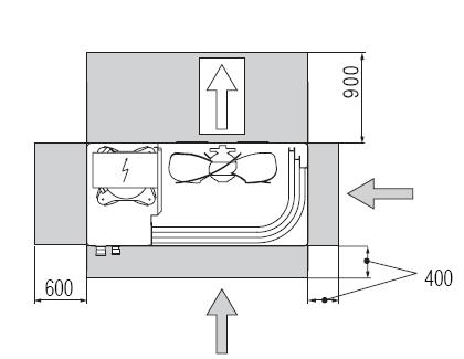
13 MCAC-ATSM R410A Mini Split Chiller 50Hz 8. Service Space 13
14 R410A Mini Split Chiller 50Hz MCAC-ATSM Piping Diagram Remark:. Name. Name. Name 1 Compressor 6 Capillary 11 Liquid receiver 2 High pressure switch 7 Liquid receiver 12 Low pressure switch 3 4 -way valve 8 Plate heat exchanger 13 Crankcase heater 4 Condenser 9 PWM valve 5 Filter 10 Water temperature sensor 14
15 MCAC-ATSM R410A Mini Split Chiller 50Hz 10. Wiring Diagrams 10.1 MGA-D10/N1 15
16 R410A Mini Split Chiller 50Hz 10.2 MGA-D12/N1 MCAC-ATSM MGA-D14/SN1 MGA-D16/SN1 16
17 MCAC-ATSM R410A Mini Split Chiller 50Hz 11. Electric Characteristics Model Power supply (V-Ph-Hz) Rated values(1) Fuses Compressors Fan/fans Pump Total Glass Max. 5 20mm values(2) 250V F.L.I. F.L.A. L.R.A. F.L.I. F.L.A. F.L.I. F.L.A. F.L.I. F.L.A. F.L.I. F.L.A. kw A A kw A kw (A) (kw) (A) (kw) (A) Fuse 1 MGA-D10/N A MGA-D12/N A MGA-D14/SN A MGA-D16/SN A Remark: F.L.I. :Full load input power. F.L.A. : Full load ampere. L.R.A.: Locked rotary ampere. (1) Outside air temperature 35 -Water temperature at evaporator 12/7. (2) Values refer to the lower rated voltage(50hz). These values are used to judge the protection switch size and the thickness of the power supply cable. 17
18 R410A Mini Split Chiller 50Hz MCAC-ATSM Capacity Tables 12.1 Cooling capacity Model MGA-D10/N1 Ta. ( C) Tw ( C) Pf (kw) Pa (kw) Pat (kw) Qev (m 3 /h) Pev (kpa) Pf (kw) Pa (kw) Pat (kw) Qev (m 3 /h) Pev (kpa) Pf (kw) Pa (kw) Pat (kw) Qev (m 3 /h) Pev (kpa) Pf (kw) Pa (kw) Pat (kw) Qev (m 3 /h) Pev (kpa) Pf (kw) Pa (kw) Pat (kw) Qev (m 3 /h) Pev (kpa) Remark: Ta: outside air temperature ( C) Tw : evaporator water outlet temperature ( C) Pf: cooling capacity (kw) Pa: compressor power input (kw) Pat: total power input (kw) Qev: evaporator water flow (m3/h) Pev: evaporator pressure drop (kpa) 18
19 MCAC-ATSM R410A Mini Split Chiller 50Hz Model MGA-D12/N1 Ta. ( C) Tw ( C) Remark: Pf (kw) Pa (kw) Pat (kw) Qev (m 3 /h) Pev (kpa) Pf (kw) Pa (kw) Pat (kw) Qev (m 3 /h) Pev (kpa) Pf (kw) Pa (kw) Pat (kw) Qev (m 3 /h) Pev (kpa) Pf (kw) Pa (kw) Pat (kw) Qev (m 3 /h) Pev (kpa) Pf (kw) Pa (kw) Pat (kw) Qev (m 3 /h) Pev (kpa) Ta: outside air temperature ( C ) Tw : evaporator water outlet temperature ( C) Pf: cooling capacity (kw) Pa: compressor power input (kw) Pat: total power input (kw) Qev: evaporator water flow (m 3 /h) Pev: evaporator pressure drop (kpa) 19
20 R410A Mini Split Chiller 50Hz MCAC-ATSM Model MGA-D14/SN1 Ta. ( C) Tw ( C) Remark: Pf (kw) Pa (kw) Pat (kw) Qev (m 3 /h) Pev (kpa) Pf (kw) Pa (kw) Pat (kw) Qev (m 3 /h) Pev (kpa) Pf (kw) Pa (kw) Pat (kw) Qev (m 3 /h) Pev (kpa) Pf (kw) Pa (kw) Pat (kw) Qev (m 3 /h) Pev (kpa) Pf (kw) Pa (kw) Pat (kw) Qev (m 3 /h) Pev (kpa) Ta: outside air temperature ( C ) Tw : evaporator water outlet temperature ( C) Pf: cooling capacity (kw) Pa: compressor power input (kw) Pat: total power input (kw) Qev: evaporator water flow (m 3 /h) Pev: evaporator pressure drop (kpa) 20
21 MCAC-ATSM R410A Mini Split Chiller 50Hz Model MGA-D16/SN1 Ta. ( C) Tw ( C) Remark: Pf (kw) Pa (kw) Pat (kw) Qev (m 3 /h) Pev (kpa) Pf (kw) Pa (kw) Pat (kw) Qev (m 3 /h) Pev (kpa) Pf (kw) Pa (kw) Pat (kw) Qev (m 3 /h) Pev (kpa) Pf (kw) Pa (kw) Pat (kw) Qev (m 3 /h) Pev (kpa) Pf (kw) Pa (kw) Pat (kw) Qev (m 3 /h) Pev (kpa) Ta: outside air temperature ( C ) Tw : evaporator water outlet temperature ( C) Pf: cooling capacity (kw) Pa: compressor power input (kw) Pat: total power input (kw) Qev: evaporator water flow (m 3 /h) Pev: evaporator pressure drop (kpa) 21
22 R410A Mini Split Chiller 50Hz MCAC-ATSM Heating capacity Remark: Model MGA-D10/N1 Ta. U.R.87% ( C) Tw ( C) Ta: outside air temperature ( C ) Tw : evaporator water outlet temperature ( C) Pt: heating capacity (kw) Pa: compressor power input (kw) Pat: total power input (kw) Qc: condenser water flow (m 3 /h) ΔPc: evaporator pressure drop (kpa) : conditions outside of operating limits Pt (kw) Pa (kw) Pat (kw) Qc (m 3 /h) Pc (kpa) Pt (kw) Pa (kw) Pat (kw) Qc (m 3 /h) Pc (kpa) Pt (kw) Pa (kw) Pat (kw) Qc (m 3 /h) Pc (kpa) Pt (kw) Pa (kw) Pat (kw) Qc (m 3 /h) Pc (kpa) Pt (kw) Pa (kw) Pat (kw) Qc (m 3 /h) Pc (kpa)
23 MCAC-ATSM R410A Mini Split Chiller 50Hz Model MGA-D12/N1 Ta. U.R.87% ( C) Tw ( C) Remark: Ta: outside air temperature ( C ) Tw : evaporator water outlet temperature ( C) Pt: heating capacity (kw) Pa: compressor power input (kw) Pat: total power input (kw) Qc: condenser water flow (m 3 /h) ΔPc: evaporator pressure drop (kpa) : conditions outside of operating limits Pt (kw) Pa (kw) Pat (kw) Qc (m 3 /h) Pc (kpa) Pt (kw) Pa (kw) Pat (kw) Qc (m 3 /h) Pc (kpa) Pt (kw) Pa (kw) Pat (kw) Qc (m 3 /h) Pc (kpa) Pt (kw) Pa (kw) Pat (kw) Qc (m 3 /h) Pc (kpa) Pt (kw) Pa (kw) Pat (kw) Qc (m 3 /h) Pc (kpa)
24 R410A Mini Split Chiller 50Hz MCAC-ATSM Model MGA-D14/SN1 Ta. U.R.87% ( C) Tw ( C) Remark: Ta: outside air temperature ( C ) Tw : evaporator water outlet temperature ( C) Pt: heating capacity (kw) Pa: compressor power input (kw) Pat: total power input (kw) Qc: condenser water flow (m 3 /h) ΔPc: evaporator pressure drop (kpa) : conditions outside of operating limits Pt (kw) Pa (kw) Pat (kw) Qc (m 3 /h) Pc (kpa) Pt (kw) Pa (kw) Pat (kw) Qc (m 3 /h) Pc (kpa) Pt (kw) Pa (kw) Pat (kw) Qc (m 3 /h) Pc (kpa) Pt (kw) Pa (kw) Pat (kw) Qc (m 3 /h) Pc (kpa) Pt (kw) Pa (kw) Pat (kw) Qc (m 3 /h) Pc (kpa)
25 MCAC-ATSM R410A Mini Split Chiller 50Hz Remark: Model MGA-D16/SN1 Ta. U.R.87% ( C) Tw ( C) Ta: outside air temperature ( C ) Tw : evaporator water outlet temperature ( C) Pt: heating capacity (kw) Pa: compressor power input (kw) Pat: total power input (kw) Qc: condenser water flow (m 3 /h) ΔPc: evaporator pressure drop (kpa) : conditions outside of operating limits Pt (kw) Pa (kw) Pat (kw) Qc (m 3 /h) Pc (kpa) Pt (kw) Pa (kw) Pat (kw) Qc (m 3 /h) Pc (kpa) Pt (kw) Pa (kw) Pat (kw) Qc (m 3 /h) Pc (kpa) Pt (kw) Pa (kw) Pat (kw) Qc (m 3 /h) Pc (kpa) Pt (kw) Pa (kw) Pat (kw) Qc (m 3 /h) Pc (kpa)

26 R410A Mini Split Chiller 50Hz MCAC-ATSM Operation Limits Cooling operation Heating operation Outdoor ambient temperature: 10 ~43 Outlet water temperature: 5-17 Outdoor ambient temperature: -15 ~24 Outlet water temperature: Cooling Heating 13.1 Ethylene glycol solution Water and ethylene glycol solutions used as a thermal vector in the place of water reduce the performance of the unit. Multiply the performance figures by the values given in the following table. Freezing point ( C) Percentage of ethylene glycol in weight 0 12% 20% 28% 35% 40% cpf cq cdp cpf: correction factor refrigerating capacity cq: correction factor flow rate cdp: correction factor pressure drop te: 1. During winter leaving the unit unused, please drain water out completely from unit if no antifreeze were charged into pipeline, or keep power on (at standby or off status) and ensure that water is contained inside of unit. 2. When ambient temperature is lower than 5, running cooling mode must be charged antifreeze. Refers to upper parameters for the charged volume Fouling factor The performance data given refer to conditions with clean evaporator plates (fouling factor=1). For different fouling factors, multiply the figures in the performance tables by the coefficient given in the following table. 26
27 MCAC-ATSM R410A Mini Split Chiller 50Hz Fouling factor Evaporator (m 2 C/W) f1 fk1 fx f1 capacity correction factor fk1 compressor power input correction factor fx1 total power input correction factor 13.3 Minimum water volume Model MGA-D10/N1 MGA-D12/N1 MGA-D14/SN1 MGA-D16/SN1 Minimum water volume (L) If the total water volume in the system is less than the value in the table above, the additional water tank is necessary in order to avoid the compressor On/Off frequency. The minimum size of the water tank is calculated as: Size of additional water tank(l)=minimum water volume (L) Actual water volume(l). 27
28 R410A Mini Split Chiller 50Hz MCAC-ATSM Hydraulic Performance 14.1 Pump head curve(*) te: (*) To obtain the useful head of the installation, subtract the pressure drop of the plate heat exchanger Heat exchanger pressure drop (water side) Model Water flow m 3 / h l/sec MGA-D10/N1 Pressure drop kpa Model Water flow m 3 / h l/sec MGA-D12/N1 kpa MGA-D14/SN1 Pressure drop kpa MGA-D16/SN1 kpa
29 MCAC-ATSM R410A Mini Split Chiller 50Hz 15. Sound Levels MGA-D10/N1 MGA-D12/N1, MGA-D14/SN1, MGA-D16/SN1 Outdoor Unit Microphone H 1.0m te: H= 0.5 height of outdoor unit te: The point A is in the middle of the whole outdoor panel. Model ise level db(a) MGA-D10/N1 57 MGA-D12/N1 60 MGA-D14/SN1 60 MGA-D16/SN
30 R410A Mini Split Chiller 50Hz MCAC-ATSM Exploded Views 16.1 MGA-D10/N1 Matched water pump box- CE-SBX/N
31 MCAC-ATSM R410A Mini Split Chiller 50Hz MGA-D10/N1. Part Name Quantity. Part Name Quantity 1 Top cover ass'y Wire joint 1 2 Rear Supporter Compressor capacitor 1 3 Condenser ass'y Wire clamp 1 4 High pressure valve ass'y 1 8 Separator Low pressure valve 1 9 Big handle 1 5 Partition board ass'y 1 10 Front right clapboard ass'y 1 6 Rear right clapboard ass'y 1 11 Valve plate 1 7 E-part box ass'y 1 12 Compressor communication wire 1 13 Branch pipe ass'y Transformer 1 14 Compressor electric heater Cable 1 15 Base ass'y Damp 1 16 Suction pipe ass'y Electric installation board Pressure controller Capacitor 1 17 Solenoid valve ass'y Capacitor installation board Pressure-relief-valve Capacitor clamp way valve ass'y Capacitor clamp Solenoid Wire clamp way valve Terminal board Low pressure valve Urgency switch Pressure controller AC contactor 1 19 Axial flow fan Wire joint ass'y 1 20 Motor Wire joint 1 21 Motor bracket ass'y Wire joint 1 22 Grille Wire joint 3 23 Front panel Wire joint 1 24 Wired controller Wire joint 1 25 Left holder Surge suppresser 1 26 Temp. sensor Caution label 1 27 Pipe temp. sensor ass'y Power supply wire 1 28 Discharge temp. sensor ass'y Main control board ass'y 1 29 Discharge temp. sensor Outdoor communication cable 1 Water pump box CE-SBX/N1-01. Part Name Quantity. Part Name Quantity 1 Up covering plate Branch pipe 2 2 Water-inlet pipe ass'y Screw Pipe joint Elbow pipe Elbow pipe Inner joint 1 3 Hook 4 19 Water charge valve 1 4 Pipe clamp I 1 20 Rear clapboard 2 5 Front clapboard 1 21 Input pipe ass'y 1 6 Pipe clamp II Pipe joint 1 7 Right cover ass'y Copper nut 1 8 Capacitor clamp 1 22 Water-outlet pipe ass'y 1 9 Water-inlet pipe supporter Water-outlet pipe ass'y I 1 10 Input pipe ass'y Drain pipe adapter Accumulator tank 1 23 Water-outlet pipe ass'y II 1 11 Water-inlet pipe ass'y Elbow pipe outer joint Water-outlet pipe II Pipe joint Pipe joint Water-inlet pipe ass'y I 1 24 Pump 1 12 Base 1 25 Water-outlet pipe ass'y I 1 13 Expansion vessel Pipe joint 3 14 Heat-exchanger plate ass'y Elbow pipe Plate Heat-exchanger 1 26 Installation bracket Elbow pipe 1 27 Big handle Pipe joint 1 28 Left clapboard ass'y Pipe hoop 1 29 Safety valve Pipe joint 1 30 Discharge valve Copper nut 1 31 Water-outlet pipe III 1 15 Target flow-volume controller 1 32 Input pipe ass'y 1 16 Clamp Accumulator tank 1 17 Water charge pipe 1 33 Temp. sensor ass'y 1 18 Water-inlet pipe ass'y II 1 34 Wire joint, 5p Pipe joint 3 31
32 R410A Mini Split Chiller 50Hz MCAC-ATSM MGA-D12/N1 Matched water pump box- CE-SBX/N1-01A 32
33 MCAC-ATSM R410A Mini Split Chiller 50Hz MGA-D12/N1. Part Name Quantity. Part Name Quantity 1 Top cover ass'y way valve ass'y 1 2 Accumulator cylinder way valve 1 3 Condenser ass'y Ways valve solenoid 1 4 Valve plate Low pressure valve 1 5 Front clapboard ass'y 1 12 Compressor 1 6 E-part box ass'y 1 13 Base AC contactor 1 14 Compressor electric heater Surge suppresser 1 15 Discharge pipe ass'y Capacitor clamp Pressure controller Compressor capacitor 1 16 Suction pipe ass'y Main control board ass'y Pressure controller Transformer Pressure-relief-valve Wire joint 1 17 Partition board ass'y Motor capacitor 2 18 Grille Wire joint, 3p 1 19 Motor Wire joint 1 20 Wired controller Electric installation board ass'y 1 21 Axial flow fan Cable 1 22 Motor bracket ass'y Power supply wire 1 23 Rear support board I Wire joint 3 24 Rear net clip Wire joint 1 25 Front panel Wire joint 1 26 Discharge temp. sensor ass'y 1 7 Urgency switch 1 27 Temp. sensor ass'y 1 8 Rear clapboard ass'y 1 28 Room temp. sensor ass'y 1 9 Handle 2 29 Discharge temp. sensor 1 10 High pressure valve ass'y 1 30 Fixing ring Low pressure valve 1 31 Rear support board II 1 Water pump box CE-SBX/N1-01A. Part Name Quantity. Part Name Quantity 1 Up covering plate Branch pipe 2 2 Water-inlet pipe ass'y Screw Pipe joint Elbow pipe Elbow pipe Inner joint 1 3 Hook 4 19 Water charge valve 1 4 Pipe clamp I 1 20 Rear clapboard 2 5 Front clapboard 1 21 Input pipe ass'y 1 6 Pipe clamp II Pipe joint 1 7 Right cover ass'y Copper nut 1 8 Capacitor clamp 1 22 Water-outlet pipe ass'y 1 9 Water-inlet pipe supporter Water-outlet pipe ass'y I 1 10 Input pipe ass'y Drain pipe adapter Accumulator tank 1 23 Water-outlet pipe ass'y II 1 11 Water-inlet pipe ass'y Elbow pipe outer joint Water-outlet pipe II Pipe joint Pipe joint Water-inlet pipe ass'y I 1 24 Pump 1 12 Base 1 25 Water-outlet pipe ass'y I 1 13 Expansion vessel Pipe joint 3 14 Heat-exchanger plate ass'y Elbow pipe Plate Heat-exchanger 1 26 Installation bracket Elbow pipe 1 27 Big handle Pipe joint 1 28 Left clapboard ass'y Pipe hoop 1 29 Safety valve Pipe joint 1 30 Discharge valve Copper nut 1 31 Water-outlet pipe III 1 15 Target flow-volume controller 1 32 Input pipe ass'y 1 16 Clamp Accumulator tank 1 17 Water charge pipe 1 33 Temp. sensor ass'y 1 18 Water-inlet pipe ass'y II 1 34 Wire joint, 5p Pipe joint 3 33
34 R410A Mini Split Chiller 50Hz 16.3 MGA-D14/SN1 MCAC-ATSM Matched water pump box- CE-SBX/SN
35 MCAC-ATSM R410A Mini Split Chiller 50Hz MGA-D14/SN1. Part Name Quantity. Part Name Quantity 1 Top cover ass'y way valve 1 2 Accumulator cylinder Ways valve solenoid 1 3 Condenser ass'y Low pressure valve 1 4 Valve plate 1 12 Compressor 1 5 Front clapboard ass'y 1 13 Base 1 6 E-part box ass'y 1 14 Compressor electric heater AC contactor 1 15 Discharge pipe ass'y Surge suppresser Pressure controller Main control board ass'y 1 16 Suction pipe ass'y Transformer Pressure controller Wire joint Pressure-relief-valve Motor capacitor 2 17 Motor bracket ass'y Wire joint, 3p 1 18 Grille Wire joint 1 19 Motor Electric installation board ass'y 1 20 Wired controller Cable 1 21 Axial flow fan Outdoor communication cable 1 22 Motor bracket ass'y Wire joint 3 23 Rear support board I Wire joint 1 24 Rear net clip Wire joint, 5p 1 25 Front panel 1 7 Urgency switch 1 26 Discharge temp. sensor ass'y 1 8 Rear clapboard ass'y 1 27 Temp. sensor ass'y 1 9 Handle 2 28 Discharge temp. sensor 1 10 High pressure valve ass'y 1 29 Room temp. sensor ass'y Low pressure valve 1 30 Fixing ring way valve ass'y 1 31 Rear support board II 1 Water pump box CE-SBX/SN1-01. Part Name Quantity. Part Name Quantity 1 Up covering plate Branch pipe 2 2 Water-inlet pipe ass'y Screw Pipe joint Elbow pipe Elbow pipe Inner joint 1 3 Hook 4 19 Water charge valve 1 4 Pipe clamp I 1 20 Rear clapboard 2 5 Front clapboard 1 21 Input pipe ass'y 1 6 Pipe clamp II Pipe joint 1 7 Right cover ass'y Copper nut 1 8 Capacitor clamp 1 22 Water-outlet pipe ass'y 1 9 Water-inlet pipe supporter Water-outlet pipe ass'y I 1 10 Input pipe ass'y Drain pipe adapter Accumulator tank 1 23 Water-outlet pipe ass'y II 1 11 Water-inlet pipe ass'y Elbow pipe outer joint Water-outlet pipe II Pipe joint Pipe joint Water-inlet pipe ass'y I 1 24 Pump 1 12 Base 1 25 Water-outlet pipe ass'y I 1 13 Expansion vessel Pipe joint 3 14 Heat-exchanger plate ass'y Elbow pipe Plate Heat-exchanger 1 26 Installation bracket Elbow pipe 1 27 Big handle Pipe joint 1 28 Left clapboard ass'y Pipe hoop 1 29 Safety valve Pipe joint 1 30 Discharge valve Copper nut 1 31 Water-outlet pipe III 1 15 Target flow-volume controller 1 32 Input pipe ass'y 1 16 Clamp Accumulator tank 1 17 Water charge pipe 1 33 Temp.sensor ass'y 1 18 Water-inlet pipe ass'y II 1 34 Wire joint, 5p Pipe joint 3 35
36 R410A Mini Split Chiller 50Hz 16.4 MGA-D16/SN1 MCAC-ATSM Matched water pump box- CE-SBX/SN1-01A 36
37 MCAC-ATSM R410A Mini Split Chiller 50Hz. Part Name Quantity. Part Name Quantity 1 Top cover ass'y way valve 1 2 Accumulator cylinder Ways valve solenoid 1 3 Condenser ass'y Low pressure valve 1 4 Valve plate 1 12 Compressor 1 5 Front clapboard ass'y 1 13 Base 1 6 E-part box ass'y 1 14 Compressor electric heater AC contactor 1 15 Discharge pipe ass'y Surge suppresser Pressure controller Main control board ass'y 1 16 Suction pipe ass'y Transformer Pressure controller Wire joint Pressure-relief-valve Motor capacitor 2 17 Motor bracket ass'y Wire joint, 3p 1 18 Grille Wire joint 1 19 Motor Electric installation board ass'y 1 20 Wired controller Cable 1 21 Axial flow fan Outdoor communication cable 1 22 Motor bracket ass'y Wire joint 3 23 Rear support board I Wire joint 1 24 Rear net clip Wire joint, 5p 1 25 Front panel 1 7 Urgency switch 1 26 Discharge temp. sensor ass'y 1 8 Rear clapboard ass'y 1 27 Temp. sensor ass'y 1 9 Handle 2 28 Discharge temp. sensor 1 10 High pressure valve ass'y 1 29 Room temp. sensor ass'y Low pressure valve 1 30 Fixing ring way valve ass'y 1 31 Rear support board II 1 Water pump box CE-SBX/SN1-01A. Part Name Quantity. Part Name Quantity 1 Up covering plate Branch pipe 2 2 Water-inlet pipe ass'y Screw Pipe joint Elbow pipe Elbow pipe Inner joint 1 3 Hook 4 19 Water charge valve 1 4 Pipe clamp I 1 20 Rear clapboard 2 5 Front clapboard 1 21 Input pipe ass'y 1 6 Pipe clamp II Pipe joint 1 7 Right cover ass'y Copper nut 1 8 Capacitor clamp 1 22 Water-outlet pipe ass'y 1 9 Water-inlet pipe supporter Water-outlet pipe ass'y I 1 10 Input pipe ass'y Drain pipe adapter Accumulator tank 1 23 Water-outlet pipe ass'y II 1 11 Water-inlet pipe ass'y Elbow pipe outer joint Water-outlet pipe II Pipe joint Pipe joint Water-inlet pipe ass'y I 1 24 Pump 1 12 Base 1 25 Water-outlet pipe ass'y I 1 13 Expansion vessel Pipe joint 3 14 Heat-exchanger plate ass'y Elbow pipe Plate Heat-exchanger 1 26 Installation bracket Elbow pipe 1 27 Big handle Pipe joint 1 28 Left clapboard ass'y Pipe hoop 1 29 Safety valve Pipe joint 1 30 Discharge valve Copper nut 1 31 Water-outlet pipe III 1 15 Target flow-volume controller 1 32 Input pipe ass'y 1 16 Clamp Accumulator tank 1 17 Water charge pipe 1 33 Temp. sensor ass'y 1 18 Water-inlet pipe ass'y II 1 34 Wire joint, 5p Pipe joint 3 37
38 R410A Mini Split Chiller 50Hz MCAC-ATSM Troubleshooting 17.1 Troubles cause and solution Troubles Causes Solution Water pump doesn t work. Water pump works while compressor does not work. Temperature of chilled or hot water abnormal. Compressor can t run automatically after stop Malfunction code 1. Voltage is out of operation range. Check wiring and circuit 2. Water flow in the water pump box is abnormal Check whether the water system is blocked with sundries. Clean the filter and refill water. 1. Open-circuit of compressor connector Check the cable connection. 2. Open-circuit of compressor wiring Check the cable connection. 1. Improper adjustment to water valve Adjust the water valve. 2. Overload Change to a bigger capacity chiller. 1. Heating in summer Change the mode into cooling mode. 2. Cooling in winter Change the mode into heating mode. Code Malfunction Code Malfunction E0 Water flow test malfunction. P0 Current protection. E1 Power phase sequence malfunction. P1 High pressure protection. E2 Indoor & outdoor unit communication checking channel is abnormal. P2 Low pressure protection. E3 Inlet temperature sensor checking channel is abnormal. P3 Discharge temperature protection. E4 Outdoor ambient temperature sensor checking channel is abnormal. P4 Inlet outlet water temperature difference protection. E5 Outlet water temperature sensor checking channel is abnormal. P5 Condenser high temperature protection. E6 Condenser temperature sensor checking channel is abnormal. P6 Plate heat exchanger low temperature protection. E7 Plate heat exchanger temperature sensor 1 checking channel is abnormal. Pb System anti-freezing protection. E8 E9 Plate heat exchanger temperature sensor 2 checking channel is abnormal. Digital scroll compressor discharge temperature sensor is abnormal (thermostat display E4). P8 Inlet temperature protection (three times in one hour and system should be powered on again).the wired controller displays P4 when spot check. 38
39 MCAC-ATSM E0: Water flow test malfunction R410A Mini Split Chiller 50Hz LED indicates E0 The water pump gets faulty. Check the water pump, and repair or replace it if necessary. Water flow switch gets faulty. Check the water flow switch, and repair or replace it if necessary. Check whether the water system is blocked. The _ T inlet water T outlet water _ >10. Check the water system and clean the filter. There is air left in the water system. Discharge the air. Check whether the circulation water is insufficient. Check and adjust the water system. 39
40 R410A Mini Split Chiller 50Hz MCAC-ATSM E1: Phase sequence malfunction LED indicates E1 Check whether the phase order of 3-phase power supply is incorrect. Exchange the power wire of any two phases. Check whether the 3-phase power supply lacks phase. Check the power supply and power wire. E2: Indoor & outdoor unit communication checking channel is abnormal LED indicates E2 Check whether the signal wires of P, Q, (E) are wrong connected. Connect them well. Check whether the wired controller and outdoor unit are all powered on. Put on the power. Replace the PCB. 40
41 MCAC-ATSM E3: Inlet water temperature sensor checking channel is abnormal R410A Mini Split Chiller 50Hz LED indicates E3 Check whether the wiring of inlet water temperature sensor is broken. Connect the wiring well. Check whether the inlet water temperature sensor is broken: see whether the resistance of inlet water temperature sensor is wrong. Replace the inlet water temperature sensor. Replace the PCB. E4: Outdoor ambient temperature sensor checking channel is abnormal LED indicates E4 Check whether the wiring of outdoor ambient temperature sensor is broken. Connect the wiring well. Check whether the outdoor ambient temperature sensor is broken: see whether the resistance of outdoor ambient temperature sensor is wrong. Replace the outdoor ambient temperature sensor. Replace the PCB. 41
42 R410A Mini Split Chiller 50Hz E5: Outlet water temperature sensor checking channel is abnormal MCAC-ATSM LED indicates E5 Check whether the wiring of outlet water temperature sensor is broken. Connect the wiring well. Check whether the outlet water temperature sensor is broken: see whether the resistance of outlet water temperature sensor is wrong. Replace the outlet water temperature sensor. Replace the PCB. E6: Condenser temperature sensor checking channel is abnormal. LED indicates E6 Check whether the wiring of condenser temperature sensor is broken. Connect the wiring well. Check whether the condenser temperature sensor is broken: see whether the resistance of condenser temperature sensor is wrong. Replace the condenser temperature sensor. Replace the PCB. 42
43 MCAC-ATSM E7: Plate heat exchanger temperature sensor 1 checking channel is abnormal R410A Mini Split Chiller 50Hz LED indicates E7 Check whether the wiring of plate heat exchanger temperature sensor 1 is broken. Connect the wiring well. Check whether the plate heat exchanger temperature sensor 1 is broken: see whether the resistance of plate heat exchanger temperature sensor is wrong. Replace the plate heat exchanger temperature sensor 1. Replace the PCB. E8: Plate heat exchanger temperature sensor 2 checking channel is abnormal. LED indicates E8 Check whether the wiring of plate heat exchanger temperature sensor 2 is broken. Connect the wiring well. Check whether the plate heat exchanger temperature sensor 2 is broken: see whether the resistance of plate heat exchanger temperature sensor is wrong. Replace the plate heat exchanger temperature sensor 2. Replace the PCB. 43
44 R410A Mini Split Chiller 50Hz E9: Digital scroll compressor discharge temperature sensor is abnormal (thermostat display E4) MCAC-ATSM LED indicates E9 Check whether air outlet is blocked by sundries. Clear the sundries to ensure smooth discharge. Check whether the condenser coil fin gets dirty. Clean the condenser. Check whether the ambient temperature is too high. Add sunshade facilities. Check whether the condenser fan is abnormal. Check the outdoor fan. Check whether the refrigerant is charged too little. Recharge the refrigerant. 44
45 MCAC-ATSM P0: Current protection R410A Mini Split Chiller 50Hz LED indicates P0 Check whether the compressor motor gets faulty. Check the compressor, and repair or replace it if necessary. Check whether the refrigerant is charged too much (the high pressure> 3.8MPa). Reduce the refrigerant. Check whether air outlet is blocked by sundries. Clear the sundries to ensure smooth discharge. Check whether the condenser coil fin gets dirty. Clean the condenser. Check whether the ambient temperature is too high. Add sunshade facilities. Check whether the condenser fan is abnormal. Check the outdoor fan. Check whether the power voltage is too low, For 1 phase unit: power voltage <198V; for 3 phase unit: <342V. Check and repair the power supply. 45
46 R410A Mini Split Chiller 50Hz P1: High pressure protection MCAC-ATSM LED indicates P1 High pressure protection. Whether the wiring between the high pressure switch and main control board is connected well and correctly. Whether the high pressure switch is broken. Connect it well. Validate: Short connect the high pressure switch socket, check whether the system can run normally. Replace high pressure switch. Whether the discharge temperature controller gets faulty. Check whether the refrigerant system is ok. Replace discharge temperature controller. Check whether the outdoor ambient temperature is too high. Check whether the outdoor unit is bad ventilation. Check whether the heat exchanger is dirty. Stop the unit. Make the outdoor unit ventilate well. Clean the heat exchanger. Check whether the refrigerant pipe is blocked. Drop refrigerant, then use the high pressure nitrogen or refrigerant to blow pipe, vacuumize and add the refrigerant again. Replace outdoor main board. 46
47 MCAC-ATSM P2: Low pressure protection R410A Mini Split Chiller 50Hz LED indicates P2 Low pressure protection. The wiring between the low pressure switch and main control board is connected well or correctly. Connect it well. Whether the low pressure switch is broken. Validate: Short connect the low pressure switch socket, check whether the system can run normally. Replace low pressure switch. Check whether the refrigerant system is ok. Check whether the outdoor ambient temperature is too low. The refrigerant of the system leakage. Validate: Connect the pressure gauge to the gauge joint of the system, check whether the pressure is lower than 0.15MPa. The refrigerant pipe is blocked. Leak hunting: charge nitrogen or refrigerant to the system, if the leakage is serious, there will be distinct gas leakage cici sound; if the refrigerant leakage is little, use the suds (mixture of water and abluent is also ok, if it can make bubble) or electronic leak detector. Drop refrigerant, then use the high pressure nitrogen or refrigerant to blow pipe, vacuumize and add the refrigerant again. Replace outdoor main board. 47
48 R410A Mini Split Chiller 50Hz P3: Discharge temperature protection Refer to the E9 to solve the problem MCAC-ATSM P4: Inlet outlet water temperature difference protection LED indicates P4 Check whether inlet outlet water temperature-sensor kits gets faulty. Replace the temperature-sensor kits. Check whether the sequence of the four temperature-sensor kits in the water pump is wrong connected. Fix it well. Check whether the water flow is too small (Q<0.6 Q rated). Adjust the water flow. P5: Condenser high temperature protection Check whether outdoor ambient temperature is too high. Compressor motor gets faulty. Add sunshade facilities. Check whether the outdoor unit s ventilation is bad. Check if there are sundries blocking the ventilation and clear them to make good ventilation. Check whether the outdoor condenser coil pipe gets dirty. Clean the condenser. 48
49 MCAC-ATSM P6: Plate heat exchanger low temperature protection R410A Mini Split Chiller 50Hz LED indicates P6 Check whether the temperature-sensor kit at the plate heat exchanger side gets faulty. Replace the temperature-sensor kit. The heat exchange of water side is insufficient. Clean the water side heat exchanger or pipe. Check whether the circulation water is insufficient. Refill water periodically. Check whether the FCU are not started. Start the FCU. 49
50 R410A Mini Split Chiller 50Hz Pb: System anti-frozen protection MCAC-ATSM LED indicates Pb Check whether the circulation water is insufficient: (Q<0.6 Q rated). Check the water system and make adjustment. Check whether the plate heat exchanger temperature sensor is abnormal. Replace the temperature sensor. Check whether the ambient temperature is too low (in cooling mode). Adjust outdoor fan and increase the outdoor air flow. P8: Inlet water temperature protection (three times in one hour and system should be powered on again). At spot checking time, the wired controller displays P Refer to the P4 to solve the problem. 50
51 MCAC-UTSM R410A Mini Split Chiller 50Hz 18. Installation 18.1 Installation of general information General warning 1. These units have been designed to chill and heat water and must be used in applications compatible with their performance characteristics; these appliances are designed for residential or similar applications. 2. Incorrect installation, regulation and maintenance or improper use absolves the manufacturer from all liability, whether contractual or otherwise, for damage to people, animals or things. Only those applications specifically indicated in this list are permitted. 3. Read this manual carefully. All work must be carried out by qualified personnel in conformity with legislation in force in the country concerned. 4. The guarantee is invalidated if the above instructions are not respected and if the unit is started up for the first time without the presence of personnel authorized by the Company (where specified in the supply contract) who should draw up a start-up report. 5. The documentation supplied with the unit must be consigned to the owner who should keep it carefully for future consultation in the event of maintenance or service. 6. All repair or maintenance work must be carried out by the Company s Technical Service or qualified personnel following the instructions in this manual. The air-conditioner must under no circumstances be modified or tampered with as this may create situations of risk. Failure to observe this condition absolves the manufacturer of all liability for resulting damage. Fundamental safety rules Prohibition This appliance is not intended for use by persons (including children) with reduced physical, sensory or mental capabilities, or lack of experience and knowledge, unless they have been given supervision or instruction concerning use of the appliance by a person responsible for their safety. Do not touch the unit with bare feet or with wet or damp parts of the body. Do not carry out cleaning operations without first disconnecting the system from the electricity supply. Do not modify safety or regulation devices without authorization and instructions from the manufacture. Do not pull, detach or twist the electrical cables coming from the unit, even when disconnected from the mains electricity supply. Do not open doors or panels providing access to the internal parts of the unit without first ensuring that the mains switch is in the off position. Do not introduce pointed objects through the air intake and outlet grills. Do not dispose of, abandon or leave within reach of children packaging materials (cardboard, staples, plastic bags, etc.) as they may represent a hazard. 1. The chiller appliances are supplied without the main switch. The power supply to the unit must be disconnected using a suitable main switch that must be supplied and installed by the installer. 2. Respect safety distances between the unit and other equipment or structures. Guarantee adequate space for access to the unit for maintenance and/or service operations; Power supply: the cross section of the electrical cables must be adequate for the power of the unit and the power supply voltage must correspond with the value indicated on the respective units. All units must be earthed in conformity with legislation in force in the country concerned. 3. Hydraulic connections should be carried out as indicated in the instructions to guarantee correct operation of the unit. Empty the water circuit or add glycol if the unit is not used during the winter. Handle the unit with the utmost care to avoid damage. 51

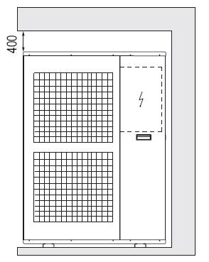
52 R410A Mini Split Chiller 50Hz 18.2 Installation MCAC-UTSM Choice of installation site Before installing the unit, agree with the customer the site where it will be installed, taking the following points into consideration: - check that the fixing points are adequate to support the weight of the unit; - pay scrupulous respect to safety distances between the unit and other equipment or structures to ensure that air entering the unit and discharged by the fans is free to circulate Positioning Before handling the unit, check the capacity of the lifting equipment used, respecting the instructions on the packaging. To move the unit in the horizontal, make appropriate use of a lift truck or similar, bearing in mind the weight distribution of the unit. To lift the unit, insert tubes long enough to allow positioning of the lifting slings and safety pins in the feet on the unit. To avoid the slings damaging the unit, place protection between the slings and the unit. Position the unit in the site indicated by the customer. Place either a layer of rubber (min. thickness 10 mm) or vibration damper feet (optional) between the base and support surface. Fix the unit, making sure it is level and that there is easy access to hydraulic and electrical components. If the site of installation is exposed to strong winds, fix the unit adequately to the support surface using tie rods if necessary. If a heat pump unit is being installed, make sure the condensate is drained using the drain hose supplied as standard. Prevent leaves, branches or snow from accumulating around the unit. These could reduce the efficiency of the unit Installation of outdoor unit Installation space 1) At least 600mm distance should be left between outdoor units: 2) Distance between foot screws is shown below: 52

53 MCAC-UTSM R410A Mini Split Chiller 50Hz Refrigerant piping te: 1. Refrigerant piping connection is on the right side of outdoor unit. 2. The piping connects to refrigerant piping connection. 3. Install the refrigerant piping towards left, right or back. 4. Refer to system identifiers in valve installation board for corresponding connections of indoor units. a. Choose the sizes of refrigerant piping: φ9.53+φ19 b. Connection: refer to connection of refrigerant piping c. Length and height drop permitted of refrigerant piping Maximum length of piping (L) Maximum height drop (Height drop between water pump box and outdoor unit H) Outdoor unit (up) Outdoor unit (down) 10m 5m 5m d. Remove dirt or water in the piping Make sure there is no any dirt or water in the piping before connecting it to the outdoor unit. Please clean the piping with high-pressure nitrogen rather than refrigerant of outdoor unit. e. Vacuuming with vacuum pump Please vacuum with vacuum pump. Vacuuming should be done from the gas side. f. Open all valves g. Refrigerant volume to be added Calculate the volume according to the diameter and the length of the liquid side piping between outdoor unit and water pump box. The refrigerant volume to be added is based on the following table: Expel the air Piping on liquid side Method Refrigerant volume to be added <5m Use refrigerant in outdoor unit 5m Use vacuum pump or refrigerant box 60g/m (length of piping -5m) 1. Flaring Cut a pipe with a pipe cutter. Insert a flare nut into a pipe and flare the pipe. 2. Fasten the nuts Put the connecting tubing at the proper position, wrench the nuts with hands then fasten it with a wrench. 53
54 R410A Mini Split Chiller 50Hz Caution MCAC-UTSM Too large torque will harm the bell-mouth and too small will cause leakage. Please determine the torque according to the table below: Pipe gauge Tightening torque Flare dimension A Min (mm) Max Flare shape Φ6.4 15~16N.m (153~163kgf.cm) Φ ~26N.m (255~265kgf.cm) Φ ~36N.m (357~367kgf.cm) Φ ~47N.m (459~480kgf.cm) Φ ~67N.m (663~684kgf.cm) How to expel the air A. Expel the air with refrigerant in outdoor unit: connect the wiring between water pump box and outdoor unit, refer to the example below: 1. Totally fasten the joint nut of stop valve B and nut C and D. 2. Loosen the joint nut of stop valve A a little. 3. For 3~5m s piping, turn the valve rod of B anticlockwise to 45 for about 6~7seconds. After the air is expelled from A, fasten the joint nut of stop valve A. (Refer to former page for the torque) 4. Totally open the valve rods of stop valve A and B. 5. Totally fasten the valve bonnet. B. Expel the air with vacuum pump (following procedures are for all the Lo-stop valve) 1. Connect the charging hose of the manifold valve with the charging inlet of the Lo-stop valve. (All the Hi-stop valves should be closed) 2. Connect the connection of charge hose with vacuum pump. 3. Totally open the Lo-lever of the manifold valve. 4. Turn on the vacuum pump. First loosen the joint nut of Lo-stop valve a little to check whether the air comes in (the noise of vacuum pump changes and the indicator of multi-meter turns to be above 0). Then fasten the joint nut. 54
55 MCAC-UTSM R410A Mini Split Chiller 50Hz 5. After vacuuming, close the Lo-lever of manifold valve and turn off vacuum pump. When doing vacuuming for more than 15 minutes, please confirm that the indicator of multi-meter points to-1.0x10⁵pa(-76cmhg) 6. Totally open the Hi-stop valve and Lo-stop valve. 7. Remove the charge hose from the charging inlet of Lo-stop valve. 8. Fasten the valve bonnets on Hi-stop valve, Lo-stop valve and on the charging inlet of Lo-stop valve. C. Expel air with refrigerant container 1. Connect the charge hose of refrigerant container with charging inlet of Lo-stop valve. 2. Fasten the joint nuts C, D and the joint nut of stop valve A. 3. Loosen the joint nut of stop valve B a little. 4. Open the valve of refrigerant container, after the refrigerant air is expelled from joint nut on Hi-stop valve side for 10~15 seconds, fasten the joint nut of stop valve B. 5. Remove the charge hose from the connection of Lo-stop valve and push the air valve core with a screw driver to discharge the refrigerant from piping until there is no noise. Then put back the air valve core at once in case the air goes into the system. 6. Remove the valve bonnet and totally open the stop valve B on high-pressure side and the valve rod on low-pressure side of the outdoor unit, then fasten the valve bonnet. 7. Make sure to fasten the valve bonnets of both Hi-stop valve and Lo-stop valve Installation of water pump box Installation location Please keep away from the following places: Such places where the temperature is high, water pump box can be installed outdoors. In other places, please install it indoors, such as washroom and the places that prevents it from water. There is combustible gas leakage. There is much salty ingredients. There is caustic gas such sulfide in the air. (The copper tubes and welding parts will be rusted and damaged, causing refrigerant to leak.) There is mineral oil, cooking oil or gasoline. (This may cause damage to plastic parts, looseness of components and leakage. A place that is too weak to bear the weight of water pump box. There is equipment that produces electromagnetic wave. (It will disturb the controlling system of air conditioner.) Install the refrigerant piping Check whether the height drop between water pump container and outdoor unit, the length of refrigerant piping, and the quantity of the bends meet the following requirements: The Max. Height drop 5m (if longer than 5m, outdoor unit should be above the water pump container.); The length of refrigerant piping shorter than 10m; The quantity of bends fewer than 15. Do not let air, dust, moisture or other impurities fall in the piping system during installation. Fix the outdoor unit and water pump box before installing the refrigerant piping. The refrigerant piping should not be installed until you check that the H-stop valve and Lo-stop valve or outdoor unit have been closed The procedures for connecting pipe 1) Connect the water inlets and water outlets of water pump box and indoor unit with soft connection and charge water into the pipe to check whether there is leakage. Then connect the outdoor unit piping. Bend the piping carefully and do not damage them. 2) The stop valve of the outdoor unit should be closed absolutely (as original state). Every time you connect it, remove the nut of stop valve then connect the flaring pipe immediately (with 5 minutes). Before connecting, use refrigerant to expel the air in the pipe. 3) Connect the Hi-stop valve and Lo-stop valve of A and B system in outdoor unit to water pump box with piping. Make sure that the connection of both outdoor unit and water pump box should be corresponding. 55
56 R410A Mini Split Chiller 50Hz MCAC-UTSM ) The flexible pipe should be used on water pump side. (The bending angle should not exceed 90. The bending part is preferably in the middle of the pipe, the bigger the bending radius, the better it is. Do not bend the pipe more than 3 times.) 5) Bending the connecting pipe of thin wall. Cut out a desired concave at the bending part of the insulating pipe. To avoid distortion or damage, please bend the pipe at its biggest radius. Use bender to get a pipe with small radius. te: Make sure to use insulation material for the copper tube which you purchase by yourself Hydraulic connection The choice and installation of components is the responsibility of the installer who should follow good working practice and current legislation. Before connecting the pipes, make sure they do not contain stones, sand, rust, dross or other foreign bodies which might damage the unit. Construction of a bypass is recommended to enable the pipes to be washed through without having to disconnect the unit (see drain valves). The connection piping should be supported in such a way as to avoid it weighing on the unit. It is recommended that the following devices are installed in the water circuit of the evaporator: A hydraulic safety valve shall be mounted in water system, which should open constantly. 1. Two pressure gauges with a suitable scale (inlet and outlet). 2. Two vibration damper joints (inlet and outlet). 3. Two gate valves (normal inlet and calibrating in outlet) 4. A flow switch (inlet) or a differential pressure switch (inlet-outlet). 5. Two thermometers (inlet and outlet). 6. An inlet filter as close as possible to the evaporator and positioned to allow easy access for routine maintenance. 7. An energy-saving water tank. 8. Additional pump. 1) The chillers must be provided with a filling/top-up system connected to the return line and a drain cock in the lowest part of the installation. Installations containing anti-freeze or covered by specific legislation must be fitted with hydraulic disconnections. 2) The manufacturer is not liable for obstruction, breakage or noise resulting from the failure to install filters or vibration dampers. Particular types of water used for filling or topping up must be treated with appropriate treatment systems. For reference values, see the table. PH 6-8 Electrical conductivity less than 200 mv/cm (25 C ) Chlorine ions Sulphuric acid ions less than 50 ppm less than 50 ppm 56
57 MCAC-UTSM R410A Mini Split Chiller 50Hz Total iron Alkalinity M Total hardness Sulphur ions Ammonia ions Silicon ions less than 0.3 ppm less than 50 ppm less than 50 ppm none none less than 30ppm Filling the installation - Before filling, check that the installation drain cock is closed. - Open all installation and terminal air vents. - Open the gate valves. - Begin filling, slowly opening the water filling cock outside the unit. - When water begins to leak out of the terminal air vent valves, close them and continue filling until the pressure gauge indicates a pressure of 1.5 bars. Emptying the installation - Before emptying, place the mains switch in the off position. - Make sure the installation fill/top-up water cock is closed. - Open the drain cock outside the unit and all the installation and terminal air vent valves. Size and position of connections Model MGA-D10/N1 MGA-D12/N1 MGA-D14/SN1 MGA-D16/SN1 Water inlet/outlet (Ø) R5/4 R5/4 R5/4 R5/4 Auto-water replenishing(ø) R1/2 R1/2 R1/2 R1/2 Security discharge(ø) G1/2 G1/2 G1/2 G1/2 Mesh filter (Ø ) R5/4 R5/4 R5/4 R5/4 Air vent (Ø ) G3/8 G3/8 G3/8 G3/8 a) The installation must be filled to a pressure of between 1 and 2 bars. b) It is recommended that this operation be repeated after the unit has been operating for a number of hours. The pressure of the installation should be checked regularly and if it drops below 1 bar, the water content should be topped-up. c) Check the hydraulic tightness of joints. d) If the fluid in the circuit contains anti-freeze, it should not be allowed to drain freely as it is pollutant. It should be collected for possible reuse. When draining after heat pump operation, take care as the water may be hot (up to 50 ). 57

58 R410A Mini Split Chiller 50Hz 18.6 Electrical connection tice MCAC-UTSM The split mini chillers leave the factory already wired, and require the installation of an omnipolar thermal overload switch, a lockable mains disconnecting switch for the connection to the mains power supply, and the connection of the flow switch to the corresponding terminals. All the above operations must be carried out by qualified personnel in compliance with the legislation in force. For all electrical work, refer to the electrical wiring diagrams in this manual. You are also recommended to check that the characteristics of the mains electricity supply are adequate for the absorptions indicated in the electrical characteristics table below, also bearing in mind the possible use of other equipment at the same time. Power to the unit must be turned on only after installation work (hydraulic and electrical) has been completed. All electrical connections must be carried out by qualified personnel in accordance with legislation in force in the country concerned. The power line should be fitted upstream with a suitable device to protect against short-circuits and leakage to earth, isolating the installation from other equipment. phase units, the unbalance between the phases must not exceed 3%). If these parameters are not respected, contact the electricity supply company. For electrical connections, use double insulation cable in conformity with current legislation in the country concerned. An omnipolar thermal overload switch and a lockable mains disconnecting switch, in compliance with the CEI-EN standards (contact opening of at least 3mm), with adequate switching and residual current protection capacity based on the electrical data table shown below, must be installed as near as possible to the appliance. The appliance shall be installed in accordance with national wiring regulations. power cord type designation is H07RN-F. An all-pole disconnection device which has at least 3mm separation distance in all pole and a residual current device(rcd)with the rating of above 10mA shall be incorporated in the fixed wiring according to the national rule. Do not use water pipes to earth the unit Electrical panel The electrical panel is located inside the unit at the top of the technical compartment where the various components of the refrigerant circuit are also to be found. To access the electrical panel, remove the front panel of the unit by undoing the screws. 58
59 MCAC-UTSM Electrical panel layout R410A Mini Split Chiller 50Hz Name Name Name 1 Power control board 4 Terminal board 7 Transformer 2 Fan capacitor 5 Emergency switch 3 Compressor capacitor 6 Compressor contactor Outdoor unit wiring specifications Model Name Quantity Specifications (for reference) tes (purchased by customers) 10.5/12kW Overall power core 1 RVV-300/ mm 2 For outdoor unit 14/16kW Overall power core 1 RVV-450/ mm 2 For outdoor unit Water-flow controlling wire 1 AWG24(7-core shielding wire) Between outdoor unit and water pump box Temp. Sensor signal wire 2 Between outdoor unit and 1 RVV-300/ mm (shielding wire) auxiliary heater 10.5/12/14/16kW 2 Between outdoor unit and Water pump power core 1 RVV-300/ mm water pump box Auxiliary heater controlling 2 Between outdoor unit and 1 RVV-300/ mm wire auxiliary heater Controlling wire for RVVP-300/ mm 2 Between outdoor unit and 1 central& wired controller Central & wired controller (2-core shielding wire) shorter than 120m Auxiliary electric heater installation 59
60 R410A Mini Split Chiller 50Hz MCAC-UTSM Maintenance 19.1 Shut down for long periods If it is previewed not to use the machine for long periods, after deactivating the chiller: Make sure the remote switch SA1 is in the "OFF" position, or alternatively disconnect the unit from the power supply. Make sure the remote keyboard (if present) is set to OFF. Position QF and QS on OFF Deactivate the indoor terminal units by placing the switch of each unit in the OFF position. Close the water valves. te: If there is a possibility that the outside temperature may drop below zero, there is the risk of freezing. The water circuit must be emptied and shut off power(when draining after heat pump operation take care as the water may be hot) or antifreeze must be added in the proportion recommended by the manufacture Routine maintenance Never perform any cleaning operations before having disconnected the unit from the mains power supply. If the supply cord is damaged, it must be replaced by the manufacturer or its service agent or a similarly qualified person in order to avoid a hazard. Regular maintenance is fundamental to maintain the efficiency of the unit both in terms of operation and energy consumption. The Technical Assistance Service maintenance plan must be observed, with an annual service which includes the following operations and checks: Filling of the water circuit. Presence of air bubbles in the water circuit. Efficiency of safety devices. Power supply voltage. Power input. Tightness of electrical and hydraulic connections. Condition of the compressor contactor. Efficiency of the plate heat exchanger heater. Checking of operating pressure, superheating and subcooling. Efficiency of compressor heater. Cleaning of finned coil (*). Cleaning of fan grills. Cleaning of condensate drain pan (if installed). (*) for Heat pump appliances, the checks are to be performed quarterly. For units installed near the sea, the intervals between maintenance should be halved Extraordinary maintenance Never perform any cleaning operations before having disconnected the unit from the mains power supply Chemical washing You are recommended to chemically wash the plate heat exchanger after every 3 years of operation Refrigerant gas content The chillers are filled R410A refrigerant gas and tested in the factory. In normal conditions, there should be no need for the Technical Assistance Service to intervene to check the refrigerant gas. However, over time, small leaks may develop at the joints leading to loss of refrigerant and draining of the circuit, causing the unit to function poorly. In this case, the leaks of refrigerant circuit refilled. Proceed as follows: 60
61 MCAC-UTSM R410A Mini Split Chiller 50Hz Empty and dry the entire refrigerant circuit using a vacuum pump connected to the low and high pressure tap until the vacuometer reads about 10Pa. Wait a couple of minutes and check that this value does not rise to more than 200Pa. Connect the refrigerant gas cylinder or a filling cylinder to the low pressure line pressure gauge connection. Fill with the quantity of refrigerant gas indicated on the rating plate of the unit. Always check the superheating and sub-cooling values. In the nominal operating conditions for the appliance, these should be between 5 and 10 C and between 4 and 8 C respectively. After a couple of hours of operation, check that the liquid indicator indicates circuit dry (dry-green) te: 1) In the event of partial leaks, the circuit must be completely emptied before being refilled The R410A refrigerant must only be filled in the liquid state. Operating conditions other than nominal conditions may produce considerably different values, Seal testing or identification of leaks must only be carried out using R410A refrigerant gas, checking with a suitable leak detector. 2) The use of a different refrigerant or oils may cause serious damage to the compressor. Oxygen, acetylene or other inflammable or poisonous gas must never be used in the refrigerant circuit as they may cause explosion or poisoning Disposal Do not dispose this product as unsorted municipal waste. Collection of such waste separately for special treatment is necessary. Do not dispose of electrical appliances as unsorted municipal waste, use separate collection systems available. If electrical appliances are disposed of in landfills or dumps, hazardous substances can leak into the groundwater and get into the food chain, damaging your health and well-being, 61


 E-heating: Display when the electric auxiliary heating water function is operated; 4) Check: Display when check function is")
62 R410A Mini Split Chiller 50Hz MCAC-UTSM Controller 20.1 Standard wired controller: KJRM-120D/BMK-E Operating instructions of buttons Operation icon 2. Mode area 3. Setting temperature 4. Timing On/Off 5. Function icon 6. On-line unit qt y. 7. Reserved 8. Clock 9. Water temp. 10.ON/OFF key 11.Right, Left key 12.OK key 13. Setting key 14. Add, reduce key 15. Cancel key 16. Reserved key Operation icon : Indicate the ON and OFF status; when it is ON, it will display; when it is OFF, it will disappear; 2. Mode area: Indicate the main unit operating mode; 3. Setting temperature: 2 status can be displayed: ; 4.Timing ON/OFF indication : Indicate the timing information; 5.Function icon: 1) Computer: Display when connects to computer; 2) Maintenance: When the icon is lighted on it means should arrange professionals to do the cleaning maintenance; long press CONSTRAINT for 3 seconds then this icon will be off, until the next maintenance; 3) E-heating: Display when the electric auxiliary heating water function is operated; 4) Check: Display when check function is operated; 5) Anti-freezing: Display when the main unit ambient temperature is below 2, to remind the main unit should be do the anti-freezing measurement; 6) Lock: When the icon is lighted on, it means the button has been locked (no keys operation for 2 minutes), long press OK key for 3 seconds to unlock; 7) Error: When the main unit has error or protection, this icon will be displayed. The unit needs to be maintained by professionals. 6. On-line unit quantity indication: Under normal status display the quantity of the units connected to the wired controller; under check status display the device serial number; 62
63 MCAC-UTSM R410A Mini Split Chiller 50Hz 7. Reserved; 8. Clock: Under normal status display clock; during timing setting it displays the setting timing time; 9. Water temperature: Under normal status display water temperature; during water temperature setting it displays the setting numerical value; under spot check status display spot check parameter; 10. ON/OFF key: On and Off functions; 11. Right, Left key: Under main page to press this key can query the setting water temperature, setting timing etc; during timing setting press the right key then shift to the next step setting; during spot check they are used to turn over the unit parameter information; 12. OK key: After setting the parameter then press this key to confirm. After keys locking then long press this key for 3 seconds to unlock; 13. Setting key: Setting the water temperature, timing, mode etc, long press this key for 3 seconds and enter to spot checking; 14. Add, Reduce key: Setting water temperature, timing, water level etc; during spot check they are used to read over #0~#15 units; 15. Cancel key: During setting parameters press this key to cancel setting. After timing setting and then long press this key 3 seconds to cancel timing; 16. Reserved key Operation instruction On and Off the main unit 1) Press the On/Off key to control On and Off status of the main unit. 2) Under Off status, press the On/Off key to operate the main unit, at that time the LCD of wired controller will display the operation icon wired controller.. The main unit will be operated as the current setting of the 3) Under On status, press the On/Off key to off the main unit, at that time the operation icon on the LCD of wired controller will disappear. Setting operating modes and parameters Press Setting key to enter the operation mode and parameters setting. The setting contents will change as the following order each time the key is pressed: WATER MODE TEMP. TIMER TEMP. DIFFERENCE 63

 Timing setting: can set 3 timing periods on the wired controller: Timer 1, Timer 2, Timer 3, and then control the main unit to ON and OFF in different periods.")
64 R410A Mini Split Chiller 50Hz MCAC-UTSM ) Setting water temperature: under main page directly press the or to adjust the water temperature, or press Setting key to enter and then press or to adjust. At that time the LCD will display Setting temperature and Water temperature parameter, as the following display. Query water temperature setting: press the or key under the main page to query the set water temperature numerical value. 2) Timing setting: can set 3 timing periods on the wired controller: Timer 1, Timer 2, Timer 3, and then control the main unit to ON and OFF in different periods. Setting method: press Setting key under main page twice to enter timing setting. At that time the LCD will display as the following: TIMER 1 ON This time the hour of the clock will flash, it means the current setting is the hour of Timer 1 On, press the or to adjust, press key when finished, and then the minute of the clock will flash, it means the current setting is the minute of Timer 1 On, press the or to adjust, press when finished, the LCD will display as the following: key TIMER1 OFF This time the hour of the clock will flash, it means the current setting is the hour of Timer 1 Off, press the or to adjust, press key when finished, and then the minute of the clock will flash, it means the current setting is the minute of Timing 1 Off, press the or to adjust, press when finished, the LCD will display as the following: key TIMER ON At this time the hour of the clock will flash, it means the current setting is the hour of the Timer 2 On, and the follow setting method will be the same of the Timer 1. Similarly, the setting of Timing 3 is the same with this method. After setting, press OK key or wait for 7 seconds then the setting to be effective, and the LCD will display the effective timing information, as the following display: 64
65 MCAC-UTSM R410A Mini Split Chiller 50Hz TIMER Example of Timing setting Main page Press Setting key twice to enter hour setting interface of Timer 1 On Through the or key, set the hour number of Timing 1 On to be 07 Press key to enter minute setting interface of Timer 1 On, adjust the minute number to be 10 Press key to enter hour setting interface of Timer 1 Off, adjust the hour number of Timer 1 Off to be 12 Press key to enter minute setting interface of Timer 1 Off, adjust the minute number to be 30 Timer 1 setting failed, after 7 seconds, the page shift to Whether press OK key Whether press key Successfully set the On time of Timer 1 to be 07:10 and Off time of Timer 1 Off to be 12:30, then back to the main page. Finish setting the On time of Timer 1 to be 07:10 and Off time to be 12:30, then enter the setting of Timer 2. The setting steps of Timer 2 and Timer 3 are the same as Timer 1, after setting all the settings then press OK key, and the3 timing periods will be effective, and then back to the main page. During any period of timing setting to press OK key, then the timing period has been set will be effective (only when the On and Off of one timing period have been set then this period setting can be finished). Press Cancel then cancel the setting. Query timing information: if query the timing hour which has been set, press or in turns. key under main page, the On and Off time of Timer1, Timer 2 and Timer 3 will be displayed Cancel timing: long press Cancel key for 3 seconds, then all the effective timing periods will be cancelled. te: To avoid the timing error, each period of timing should not be crossed. E.g.: TIMER 1 TIMER 2 TIMER 3 Correct: 5:00 8:00 10:00 12:00 18:00 22:00 TIMER 1 TIMER 2 Wrong: 5:00 7:00 8:00 12:00 3) Set working mode (valid when wired controller set to 2,3,4) 65

 Set clock This time the hour of the clock will flash, it means the current setting is the hour of the clock, press the or to adjust, press key when finished, and then the minute of the clock will")
66 R410A Mini Split Chiller 50Hz MCAC-UTSM Press SET key 3 times to enter the working mode setting when the main unit is off power. press the or key to adjust, press OK key or wait for 7 seconds to be effective, and back to the main page; During setting process to press Cancel key then will exit without saving. The controller will show different working mode when it is applied to different main unit and set to 2,3,4 respectively. te: Working mode setting is valid only when the unit is power off. 4) Set clock This time the hour of the clock will flash, it means the current setting is the hour of the clock, press the or to adjust, press key when finished, and then the minute of the clock will flash, it means the current setting is the minute of the clock, press the or to adjust, press OK key when finished or wait for 7 seconds to be effective; during the setting process press the Cancel key, then it will exit without saving. te: For getting the correct timing on and timing off hour, please correctly set the clock! Combination of key functions 1) HYSTERESIS setting function a. Through the hysteresis setting, the system can adjust the load effectively. b. The adjusting logic of cooling mode: (the parameter of δ1,δ2,tj1 and Tj2 are decided by the outdoor unit) 66
 T Ts-δ2 T <Ts+1-δ Ts-1+δ>T Ts+1-δ Ts-1+δ T <Tj2 T Tj2 (TAL: total outlet water temperature)")

 ADDRESS setting function The address of wired controller can be set by pressing this button. The address range 0~15, therefore, 16 wired controller could be parallel at most.")
67 MCAC-UTSM R410A Mini Split Chiller 50Hz c. The adjusting logic of heating mode: (the parameter of δ1,δ2,tj1 and Tj2 are decided by the outdoor unit) T Ts-δ2 T <Ts+1-δ Ts-1+δ>T Ts+1-δ Ts-1+δ T <Tj2 T Tj2 (TAL: total outlet water temperature) Operation method: Turned off, press the "Constrain" " " 2 button for 3 seconds to enter the hysteresis setting selection. Can be adjusted Hysteresis parameter δ = (2,3,4,5 C). Press or key to select the desired value, 7S key operation Or press the Enter key, then exit and save the settings and return to the main page. During setup, press the "Cancel" key, does not save the parameters and exit. The factory default δ = 2 C. 2) ADDRESS setting function The address of wired controller can be set by pressing this button. The address range 0~15, therefore, 16 wired controller could be parallel at most. Operation method: Press Constraint " seconds to enter the wired remote address selection. Press or " two button for 3 key to select the desired value. 7S key operation or press OK key to exit and save the settings and return Page. t saved during set up, press the Cancel key parameters and exit. 3) The fault is cleared This feature can clear the fault and protection has been ruled out. Methods of operation: press the "Constraint" " " two button for 3 seconds to clear the fault. Page of the main page and Inspection press this key combination, you can clear the entire system fault, the fault code cleared at the same time Check 1) Check function allows the user to query all the operating parameters and error and protection information of the main unit. 2) Enter method: long press Set key for 3 seconds to enter check interface, as the figure display: 67


68 R410A Mini Split Chiller 50Hz MCAC-UTSM ) Press the or key to adjust the main unit serial number can query 16 sets main units status information from #0~#15. Press or to adjust the spot check sequence number of one main unit then can query all the status information of this unit. Spot check content according to the main unit model wired controller : 1 outlet water temperature Tou->2 inlet water temperature Tin-> 3 outdoor ambient temperaturest4->4 outdoor pipe temperaturet3a-> 5 outdoor pipe temperaturet3b->6 current of the compressor IA-> 7 current of the compressorib->8 anti-frozen temperature T6-> 9 electronic expansion valv openingfa->10 electronic expansion valv openingfb-> 11 Last one error or protection ->12 Last second error or protection-> 13 Last third error or protection ->1 outlet water temperature Tou Error alarm handling When the unit has error or protection, icon will be flashed. Long press Setting for 3 seconds to enter spot check, and then press the or key to query the unit of 0-15#, if the error icon was on during query, that means the corresponding outdoor unit has error or protection at that time, and then can spot check the last 1, 2, 3 times error or protection of this outdoor unit. After clear the error or protection, the error icon will disappear Installation procedure Use PQE connect with each other when several wired-controllers are parallel. 68
 Operating environment temperature of wired controller: -10")
 Touch key operation; 2) LCD displays operation parameters; 3) Multiple timer; 4) Buzzer prompt tone and alarm functions; 5)")
69 MCAC-UTSM The wiring procedure and principles are shown in the figure: R410A Mini Split Chiller 50Hz Basic conditions of operating the wired controller: 1) Applicable range of supply voltage: Input voltage is 10V AC. 2) Operating environment temperature of wired controller: -10 C~+43 C. 3) Operating RH of wired controller: RH 40%~RH90% Main functions of this wired controller as follows: 1) Touch key operation; 2) LCD displays operation parameters; 3) Multiple timer; 4) Buzzer prompt tone and alarm functions; 5) Real-time clock function. te: The MODBUS gateway can be customized, the MODBUS protocol built in wired controller KJRM-120D/BMK-E, through the X/Y/E communication port of KJRM-120D/BMK-E to realize BMS system. 69
Part 1 General Information... 1 Part 2 Outdoor Unit... 4 Part 3 Installation... 45
 Contents Part 1 General Information... 1 Part 2 Outdoor Unit... 4 Part 3 Installation... 45 The specifications, designs, and information in this book are subject to change without notice for product improvement.
Contents. Part 1 General Information...2 Part 2 Outdoor units...7 Part 3 Installation...63 Part 4 Controller...79
 MCAC-TSM-2008-02 Contents Part 1 General Information...2 Part 2 Outdoor units...7 Part 3 Installation...63 Part 4 Controller...79 Contents i MCAC-TSM-2008-02 Introduction Introduction Midea Mini Unitary
Mini unitary chiller. Mini unitary chiller
 Mini unitary chiller Mini unitary chiller Product description Features and benefits Description of main components Specification Operation limits Hydraulic performance Dimension Service space Piping diagram
Aqua Mini Full DC Inverter Unitary Chiller 50Hz. Content
 MCAC-ATSM-2014-09 Content 1. Outdoor units lineup... 2 2. Nomenclature... 3 3.Features... 4 4. Description of main components... 8 5. Specifications... 10 6. Dimensions... 14 7. Piping Diagram... 15 8.
Mini Spilt Chiller &Mini Unitary Chiller 50Hz 2012
 MCAC Mini Spilt Chiller &Mini Unitary Chiller Hz Coercial Air Conditioner Business Units Midea Air Conditioning and Refrigeration Sector Add: est region of Midea coercial air conditioner department, Industry
MINI CHILLER INVERTER H4 Service manual MUENR-H4 (5, 7, 10, 12, 14, 16 kw)
") MINI CHILLER INVERTER H4 Service manual MUENR-H4 (5, 7, 10, 12, 14, 16 kw) CL25610 to CL25615 English Content 1. Outdoor units lineup... 2 2. Nomenclature... 3 3.Features... 4 4. Description of main components...
MINI CHILLER INVERTER H4 Service manual MUENR-H4 (5, 7, 10, 12, 14, 16 kw) CL25610 to CL25615 English Content 1. Outdoor units lineup... 2 2. Nomenclature... 3 3.Features... 4 4. Description of main components...
Product Data. Features/Benefits. 30RQ Air-cooled Modular Chiller R22 & R410A & R407C
 Product Data 30RQ Air-cooled Modular Chiller R22 & R410A & R407C Introduction Air-cooled modular chiller is a kind of central airconditioning unit which adopts air as the cooling (or heating) source and
Service manual. MIV V4+ Mini
 DM12-01.01.05en Service manual MIV V4+ Mini DC INVERTER R410A (~220V, 50Hz, 1Ph) MVUH80A-VA1 Contents Part 1 General Information... 1 Part 2 Outdoor Units... 6 Part 3 Installation... 44 DM12-01.01.05en
MANUAL DE INGENIERIA. Part 1 General Information... 1 Part 2 Indoor Units... 6 Part 3 Outdoor Units... 30
 MANUAL DE INGENIERIA Evaporadora Sopladora 'MVA' con Condensadora 'MOV' - Blue Star Part 1 General Information... 1 Part 2 Indoor Units... 6 Part 3 Outdoor Units... 30 Part 1 General Information 1. Model
COMMERCIAL AIR CONDITIONERS. Aqua Mini Chiller 50/60Hz
 COMMERCIAL AIR CONDITIONERS Aqua Mini Chiller 50/0Hz Midea CAC (MCAC) As a key subsidiary of Midea Group, the Midea Central Air Conditioner (MCAC) business unit has emerged as a leading supplier of commercial
Floor-Standing Type(E Series)
") Floor-Standing Type(E Series) Model: MFE-60CE, MFE-60AE Part 1. Product Features With a spiral shape, the computer-aided simulation designed air passage system can efficiently reduce noise. The Soft touch
Floor-Standing Type(E Series) Model: MFE-60CE, MFE-60AE Part 1. Product Features With a spiral shape, the computer-aided simulation designed air passage system can efficiently reduce noise. The Soft touch
R22 air-cooled modular chiller 50Hz unit. Content
 Content 1.Nomenclature... 2 2.Product Schedule... 2. External Appearance... 4.Features... 4 5.Specification... 6 6.Dimension... 10 7.Refrigeration System Sketch Drawing... 14 8.Wiring Diagrams... 16 9.Electric
Part 1 General Information... 1 Part 2 Indoor Units... 7 Part 3 Outdoor Units Part 4 Installation Part 5 Control...
 MCAC-UTSM-2008-11 Contents Part 1 General Information... 1 Part 2 Indoor Units... 7 Part 3 Outdoor Units... 88 Part 4 Installation... 127 Part 5 Control... 136 The specifications, designs, and information
UCV CONDENSING UNITS SPECIFICATIONS 1. Specifications
 UCV CONDENSING UNITS SPECIFICATIONS 1. Specifications Model UCV-76C UCV-96C Code 220075900040 220075900020 Power supply V- Ph-Hz 380-415~3~50 Capacity Btu/h 76000 96000 Cooling Input W 8100 10000 Rated
Service Manual. Air Conditional
 Air Conditional Service Manual Большая библиотека технической документации http://splitoff.ru/tehn-doc.html каталоги, инструкции, сервисные мануалы, схемы. -2 - MODEL: AC-FR30CM -3 - CONTENTS SPECIFICATION...
Air Cooled Scroll Chiller
 Air Cooled Scroll Chiller Midea chillers use H shape heat at air side and single unit s capacity from kw to 0kW. Super chillers are divided to SS,SS-LA, SP-LA and SP-HMLA series according to their water
Midea R410A Tropical ClimaCreator Series Rooftop Package 220V 3Ph 60Hz Technical Manual
 Midea R410A Tropical ClimaCreator Series Rooftop Package 220V 3Ph 60Hz Technical Manual Midea reserves the right to discontinue, or change specification or designs at any time without notices and without
[U] Serie MOV. Manual de Ingeniería
![[U] Serie MOV. Manual de Ingeniería](/thumbs/82/86228730.jpg "[U] Serie MOV. Manual de Ingeniería") [U] Serie MOV Uniidades Condensadoras (Fllujjo Verttiicall) 6..3,, 8 y 12..5 Ton Manual de Ingeniería - 112- Outdoor Units_MOV 1. Specifications.... 2. Dimension... 3. Service Space. 4. Piping Diagrams
[U] Serie MOV Uniidades Condensadoras (Fllujjo Verttiicall) 6..3,, 8 y 12..5 Ton Manual de Ingeniería - 112- Outdoor Units_MOV 1. Specifications.... 2. Dimension... 3. Service Space. 4. Piping Diagrams
CHGV AIR COOLED WATER CHILLER WITH HYDRAULIC EQUIPMENT AIR / WATER 47 to 78 kw
 TECHNICAL INSTRUCTIONS CHGV AIR COOLED WATER CHILLER WITH HYDRAULIC EQUIPMENT AIR / WATER 47 to 78 kw CHGV CHGV 64 CHGV 72 CHGV 80 PHRV heat pump model also available May 2006 10 12 167 - GB - 00 MARKING
AIR COOLED FREE-COOLING CHILLERS WITH SCROLL COMPRESSORS AND AXIAL FANS
 RAE 1352 F.K + MV AIR R-407C FC Series RAE... F.K Cooling capacity from 77 to 289 kw - 2 circuits The air cooled chillers of RAE... F.K series, are designed for outdoor installation and are particularly
SERVICE MANUAL CONDENSING UNIT ASE-18AH, ASE-24AH, ASE-36AH, ASE-48AH, ASE-60AH
 SERVICE MANUAL CONDENSING UNIT ASE-18AH, ASE-24AH, ASE-36AH, ASE-48AH, ASE-60AH Outdoor Units - appearance 18,000Btu/h 30,000~36,000Btu/h 24,000Btu/h 48,000Btu/h-60,000Btu/h Model Names of Outdoor Units
SLS 1202 to With or without total heat recovery. u Air Cooled Screw Chillers. 262 to 916 kw. Engineering Data Manual
 u Air Cooled Screw Chillers SLS 1202 to 4004 With or without total heat recovery 262 to 916 kw Engineering Data Manual EDM SLS407-A.4GB Date : December 2008 Supersedes : TM SLS407-A.3GB/11.06 Specifications
Wired controller KJR-08B/BE. Run. Fault. TB Tot. Out. Query. Heat. Net-On. Turn-On Mode
 R0A (kw-0kw) 0Hz KJR-0B/BE is a human-machine interaction(hmi) used for the communication between chiller operator and main board on the chiller itself. The setting and operation order can be send to the
Epsilon Echos kw. General information Air-Water unit with scroll compressors driven by DC inverter. Unique selling points
 Epsilon Echos+ 5 38 kw General information Air-Water unit with scroll compressors driven by DC inverter Configuration /LN: Low noise unit /HP: Reversible heat pump /LE /HP: Reversible condensing unit Unique
SMART. 4,9 49,5 kw. Air cooled liquid chillers and heat pumps equipped with scroll compressor and axial fans T_SMT_0609_GB
 T_SMT_0609_GB 4,9 49,5 kw Air cooled liquid chillers and heat pumps equipped with scroll compressor and axial fans INDEX SERIES IDENTIFICATION... 3 MODEL IDENTIFICATION... 3 CE CONFORMITY... 3 WORKING
Amendment Sheet. Nomenclature M 5 AC V 100 C R - F X AA. Code : M5ACV Date : Superceded : M5ACV
 Amendment Sheet Code : M5ACV-2005-0002 Date : 08-05-2006 Superceded : M5ACV-2005-0001 Nomenclature Production spec variation Type of ref. connection X : Not applicable Electrical A : 220-240V/1Ph/50Hz
Service Manual. Air Conditional
 Air Conditional Service Manual Большая библиотека технической документации http://splitoff.ru/tehn-doc.html каталоги, инструкции, сервисные мануалы, схемы. -2 - MODEL: AC-FR30HM -3 - CONTENTS SPECIFICATION...
MODULAR CHILLER. R410a R22
 Ra R 3 Ra/-0 R/-0 New ppearance New Y-shape design, more fashion IR-COOLED SERIES (Ra) Compressor ir cooling side heat exchanger Best scroll compressor, low sound power level, By using calculation model
FALCON Rooftop Units ACPSE 50/60Hz Cooling Capacity : 36 to 1388 MBH (11 to 407 kw) Heating Capacity : 40 to 1298 MBH (12 to 380 kw)
 Heating Capacity : 40 to 1298 MBH (12 to 380 kw)") FALCON Rooftop Units ACPSE 50/60Hz Cooling : 36 to 1388 MBH (11 to 407 ) Heating : 40 to 1298 MBH (12 to 380 ) R Products that perform...by people who care NOMENCLATURE 6 AC P S E 435 P - HP G Q 6-60 Hz
FALCON Rooftop Units ACPSE 50/60Hz Cooling : 36 to 1388 MBH (11 to 407 ) Heating : 40 to 1298 MBH (12 to 380 ) R Products that perform...by people who care NOMENCLATURE 6 AC P S E 435 P - HP G Q 6-60 Hz
AIR COOLED CHILLERS WITH SCROLL COMPRESSORS AND CENTRIFUGAL FANS
 RAE 201 C K RAE 482 C K AIR R-407C Series RAE... C K from 19 to 83 kw - 1 and 2 circuits The air cooled chillers of RAE... C K series, with centrifugal fans, are designed for indoor installation and are
CHGV AIR COOLED WATER CHILLER WITH HYDRAULIC EQUIPMENT AIR / WATER 47 to 78 kw
 TECHNICAL INSTRUCTIONS CHGV AIR COOLED WATER CHILLER WITH HYDRAULIC EQUIPMENT AIR / WATER 47 to 78 kw CHGV 50 CHGV 64 CHGV 72 CHGV 80 PHRV heat pump model also available November 2007 10 12 167 - GB -
.2 Section Waste Management and Disposal.
 Issued 2005/06/01 Section 15624 Packaged Rotary Screw Water Chillers Page 1 of 5 PART 1 General 1.1 RELATED SECTIONS.1 Section 01330 Submittal Procedures..2 Section 01355 Waste Management and Disposal..3
CHGV AIR COOLED WATER CHILLER WITH HYDRAULIC EQUIPMENT AIR / WATER 21 to 39 kw
 TECHNICAL INSTRUCTIONS CHGV AIR COOLED WATER CHILLER WITH HYDRAULIC EQUIPMENT AIR / WATER 21 to 39 kw CHGV 22 CHGV 2 CHGV 32 CHGV 40 PHRV heat pump model also available September 2007 10 12 11 - GB - 02
WATER COOLED HEAT PUMP VERTICAL UNIT CONSOLE TYPE OR RECESSED
 EQV R-407C WATER COOLED HEAT PUMP VERTICAL UNIT CONSOLE TYPE OR RECESSED Size Cooling Heating [kw] [kw] 5 1,9 2,2 7 2,4 2,5 9 2,6 2,5 15 3,3 3,2 17 3,7 3,7 REPLACE: BT02E008GB-01 The Versatemp EQV units
MODEL: CCT 301 INV CCT 501 INV CCT 70 INV-S CCT 100 INV-S CCT 140 INV-S CCT 170 INV-S
 MODEL: CCT 301 INV CCT 501 INV CCT 70 INV-S CCT 100 INV-S CCT 140 INV-S CCT 170 INV-S Compact Four-way Cassette Type 1. Features... 2. Specification... 3. Dimension... 4. Service Space... 5. Wiring Diagram...
Service Manual. Multi Split Type Heat Pump Air Conditioners. Applied to: HS-9U2IM_HOS-18U2IM HS-9U11IM_HS-12U11IM_HOS-21U11IM
 Service Manual Multi Split Type Heat Pump Air Conditioners Applied to: HS-9U2IM_HOS-18U2IM HS-9U11IM_HS-12U11IM_HOS-21U11IM CONTENT 1. Product features 2. Specification 3. Dimensions 4. Refrigeration cycle
SERVICE MANUAL 42QHF009DS* 42QHF012DS* 42QHF018DS* 42QHF022DS* 38QUS009DS* 38QUS012DS* 38QUS018DS* 38QUS022DS* Indoor unit.
 SERVICE MANUAL Indoor unit Outdoor unit 42QHF009DS* 42QHF012DS* 42QHF018DS* 42QHF022DS* 38QUS009DS* 38QUS012DS* 38QUS018DS* 38QUS022DS* INDEX PART1 GENERAL INFORMATION PART2 ELECTRICAL DIAGRAM PART3 TROUBLE
AIR COOLED CHILLERS FOR OUTDOOR INSTALLATION WITH INTEGRATED FREE COOLING MULTISCROLL SERIES
 AIR COOLED CHILLERS FOR OUTDOOR INSTALLATION WITH INTEGRATED FREE COOLING MULTISCROLL SERIES COOLING CAPACITY FROM 76 TO 612 Kw 1 AND 2 COOLING CIRCUITS RAE 1702 F Kc + P2 28 Above picture is only indicative
Zeta Rev LN HP Prochill Bluebox Print Date: 07/17/2017
 Zeta Rev LN HP 10.2 Configured unit accessories 1PS - One user-side pump with tank LN - Low noise RG - Condensation control with fan speed regulator CSP - Set point compensation depending on external air
MULTIPLO PF Multifunction chillers for indoor installation. Cooling Capacity: kw Heating Capacity: kw
 Multifunction chillers for indoor installation. Cooling Capacity: 22 222 Heating Capacity: 25 236 Scroll compressors EC Plug Fans Plate type heat exchangers EER up to 3,12 COP up to 3,84 ESEER up to 4,01
Air-Cooled Mini Chiller. Models: AMAC 040 A/AR AMAC 050 A/AR AMAC 058 A/AR AMAC 075 B/BR AMAC 100 B/BR AMAC 125 B/BR. Manual No: TMA-AMAC-1161
 Models: AMAC 040 A/AR AMAC 050 A/AR AMAC 058 A/AR AMAC 075 B/BR AMAC 100 B/BR AMAC 125 B/BR Air-Cooled Mini Chiller Manual No: TMA-AMAC-1161 REGISTERED ISO 9002 CONTENTS PAGE 1. NOMENCLATURE SYSTEM...
AIR COOLED CHILLERS WITH SCROLL COMPRESSORS AND CENTRIFUGAL FANS
 RAE 1402 C O K AIR R-407C Series RAE... C K Cooling capacity from 81 to 250 kw - 2 circuits The air cooled chillers of RAE C K series, with centrifugal fans, are designed for indoor installation and are
MACH N-407 Heat Pump Air-Cooled Chiller
 MACH060-01-N-407 Heat Pump Air-Cooled Chiller Heat Pump Air-Cooled Chillers for Global Residential and Light Commercial Microclimates MACH NOMENCLATURE BREAKDOWN MACH-060-01 - N - 407 Refrigerant Type
DYNACIAT LGN. Description. Split system Water chillers. High energy efficiency Compact and quiet Scroll compressors Brazed-plate heat exchangers
 High energy efficiency Compact and quiet Scroll compressors Brazed-plate heat exchangers Self-adjusting electronic control Cooling capacity: 35 to 700 kw 410A Cooling Operation DYNACIAT - DYNACIAT POWER
Ultimate energy saving technology
 Ultimate energy saving technology CWT Chiller Series CWt purestream series water chillers The new CWT Purestream chiller range is specifically designed to meet the stringent cooling requirements of today
Air cooled industrial chillers
 Air cooled industrial chillers Main features R410A refrigerant Cooling capacity 5 175 kw Air cooled industrial chillers Models Versions HE High Efficiency Finned coil evaporators submerged in the storage
Technical Support Division GD CHIGO HEATING & VENTILATION EQUIPMENT CO., LTD.
 Technical Support Division 2017-4-25 New CMV System - Floor ceiling Indoor Unit 1 1. External appearance 2. Nomenclature 3. Specifications 4. Dimensions 5. Service space 6. Piping diagram 7. Wiring diagram
Air-to-water scroll chillers
 Air-to-water scroll chillers Model CGA 040 to 115 Cooling capacity: 14-40 kw CG-PRC031B-GB Table of Contents Technical specifications...4 Standard configuration... 4 Hydraulic version... 4 Casing... 4
GPE Kc UNITS FOR 4-PIPE SYSTEMS WITH SCROLL COMPRESSORS. COOLING CAPACITY FROM 77 TO 426 kw - 2 COOLING CIRCUITS. GPE 802 Kc + CF + GP + MV + P1
 UNITS FOR 4-PIPE SYSTEMS WITH SCROLL COMPRESSORS COOLING CAPACITY FROM 77 TO 426 kw - 2 COOLING CIRCUITS GPE 802 Kc + CF + GP + MV + P1 130 Above picture is only indicative and is not binding. AIR R-410A
SELF-PRIMING JET PUMPS
 SS Anti-Rust SS Shaft Copper & Cold-rolled SELF-PRIMING JET PUMPS CONTENTS 1. Applications.... Model Description.... Technical Data... 4. Implementation Standards... 5. Safety Precautions... 6. Product
Contour TM Screw Compressors
 Contour TM Screw Compressors Semi-Hermetic Compact Operating Instruction SCH1 High Temp Compressors Form No. 99-77 1. Introduction This series of semi-hermetic compact screw compressors is designed for
EASY_R R407C. Air cooled liquid chillers and heat pumps equipped with scroll compressor and axial fans. 5,2 41,5 kw T_ESY_R_0508_GB
 R407C EASY_R Air cooled liquid chillers and heat pumps equipped with scroll compressor and axial fans 5,2 41,5 kw T_ESY_R_0508_GB EASY_R R407C INDEX WORKING LIMITS... 3 SERIES IDENTIFICATION... 4 MODEL
Ultimate energy saving technology
 Ultimate energy saving technology CWT Chiller Series CWt purestream series water chillers The new CWT Purestream chiller range is specifically designed to meet the stringent cooling requirements of today
1. Outdoor units lineup
 Content 1. OUTDOOR UNITS LINEUP... 2 2. NOMENCLATURE... 3 3. FEATURES... 4 4. DESCRIPTION OF MAIN COMPONENTS... 7 5. SPECIFICATIONS... 9 6. DIMENSIONS... 13 7. PIPING DIAGRAM... 14 8. WIRING DIAGRAM...
PDF Created with deskpdf PDF Writer - Trial ::
 Instruction Manual Index Introduction Uncrating and Checking for Damage Locating Your Unit Installation Fill Tank Process Connections Pre Startup Startup Sequence Trouble Shooting Chart Operating Lights
30GH Air-Cooled Liquid Chillers 30GH Nominal cooling capacity kw
 Air-Cooled Liquid Chillers Nominal cooling capacity 21-94 kw Carrier is participating in the Eurovent Certification Programme. Products are as listed in the Eurovent Directory of Certified Products. The
MAC N-407 Air-Cooled Chiller
 MAC036-01-N-407 Air-Cooled Chiller Air-Cooled Chillers for Global Residential and Light Commercial MicroClimates MAC036 NOMENCLATURE BREAKDOWN MAC036-01 - N - 407 Refrigerant Type Air-Cooled Chiller 036=
Midea R410A Domestic Pools & Spas Heat Pump Water Heater 50Hz A1 Series Technical Manual
 Midea R410A Domestic Pools & Spas HPWH 50Hz Technical Manual MCAC-HTSM-201409 Midea R410A Domestic Pools & Spas Heat Pump Water Heater 50Hz A1 Series Technical Manual Applicable Model: (New CE safety directive)
Warning: 230V / 1ph / 50Hz V / 3ph / 50Hz. Remarks: Make sure that you have enough power. (See page 15 Cable table)
") 1 2 Warning: - Do not place your hand or any other objects into the air outlet and fan. It could damage the heat pump and cause injuries; - In case of any abnormality with the heat pump, cut off the power
1 2 Warning: - Do not place your hand or any other objects into the air outlet and fan. It could damage the heat pump and cause injuries; - In case of any abnormality with the heat pump, cut off the power
Content. Part 1 General Information Part 2 Indoor Units Part 3 Outdoor Units Part 4 Installation Part 5 Control...
 R410A Tropical Split Type AC Technical Manual Content Content Part 1 General Information... 2 Part 2 Indoor Units... 6 Part 3 Outdoor Units... 88 Part 4 Installation... 120 Part 5 Control... 154 Indoor
Koolman Air-Coolded Water Chiller With Heat Pump Option
 Koolman Air-Coolded Water Chiller With Heat Pump Option CGAK/R 030-150 9.8~39 kw PKGP-PRC006-EN Contents Features and Benefits 4 Mechanical Specifications 5 Model Nomenclature 6 Performance Data 7 Dimensions
inverter mini chiller
 inverter mini chiller TRUST AIR CONDITIONING EQUIPMENT CO. Prepared By: Engineering & R & D Department. Shiraz- May 2017 Content 1. OUTDOOR UNITS LINEUP... 2 2. FEATURES... 3 3. DESCRIPTION OF MAIN COMPONENTS...
Air Conditioner Service Manual
 Air Conditioner Service Manual Большая библиотека технической документации http://splitoff.ru/tehn-doc.html каталоги, инструкции, сервисные мануалы, схемы. 2 MODEL: AC-S7HGB 3 CONTENTS TECHNICAL SPECIFICATION..4
Floor-Standing Type(S2 Series)
") Floor-Standing Type(S2 Series) Model: MFS2-24CR(N2), MFS2-24HR(N2), MFS2-24AR(N2), MFS2-48CR(N2), MFS2-48AR(N2) Part 1. Product Features Strong air supply. Wide angle and long distance air supply. Easy
Floor-Standing Type(S2 Series) Model: MFS2-24CR(N2), MFS2-24HR(N2), MFS2-24AR(N2), MFS2-48CR(N2), MFS2-48AR(N2) Part 1. Product Features Strong air supply. Wide angle and long distance air supply. Easy
CMA CONDENSING UNITS FOR OUTDOOR INSTALLATION INSTALLATION AND OPERATION MANUAL
 CMA CONDENSING UNITS FOR OUTDOOR INSTALLATION ECO-FRIENDLY REFRIGERANT GAS INSTALLATION AND OPERATION MANUAL Dear Customer, Thank you for having purchased a FERROLI product. It is the result of many years
Acquaer Ltd. H-4900, Fehérgyarmat, Szatmári út 11. CENTRIFUGAL PUMP Instruction Manual ACm60 / ACm75 / ACm150 / ACm150B2
 CENTRIFUGAL PUMP Instruction Manual ACm60 / ACm75 / ACm150 / ACm150B2 Congratulations on your purchase of a LEO Centrifugal Pump It is important that you read, fully understand and observe the following
RAH Ka AIR COOLED WATER CHILLERS WITH SCREW COMPRESSORS AND AXIAL FANS. COOLING CAPACITY FROM 387 TO 1207 kw 1 AND 2 COOLING CIRCUITS
 AIR COOLED WATER CHILLERS WITH SCREW COMPRESSORS AND AXIAL FANS COOLING CAPACITY FROM 387 TO 1207 kw 1 AND 2 COOLING CIRCUITS RAH 602 Ka + CF + GP 62 Above picture is only indicative and is not binding.
Большая библиотека технической документации каталоги, инструкции, сервисные мануалы, схемы.
 Air Conditioner Service Manual Большая библиотека технической документации http://splitoff.ru/tehn-doc.html каталоги, инструкции, сервисные мануалы, схемы. 2 Model: AC-S10CG 3 Content Technical specification..
LOW STATIC HYDRONIC DUCTED UNIT
 LOW STATIC HYDRONIC DUCTED UNIT PDWA-~AC SERIES PDWA(4R)-~-V-MEDC PDWA(4R)-~-V-MEEU PDWA(R)-~-V PDWA(R+1)-~-P Model cooling capacity( KW) at Medium Speed cooling capacity (KW) at Medium Speed cooling capacity
Midea Precision Air Conditioner Technical Manual (Down delivery series)
") Midea Precision AC Technical Manual-Down Delivery Series MCAC-RTSM-2013-04 Midea Precision Air Conditioner Technical Manual (Down delivery series) Midea reserves the right to discontinue, or change specification
Midea Precision AC Technical Manual-Down Delivery Series MCAC-RTSM-2013-04 Midea Precision Air Conditioner Technical Manual (Down delivery series) Midea reserves the right to discontinue, or change specification
Klimaire 16 SEER CENTRAL DUCTED YEAR. Central Air Conditioning & Heat Pump Systems Multi Position Air Handling Units LIMITED GUARANTEE
 Klimaire 16 SEER CENTRAL DUCTED Central Air Conditioning & Heat Pump Systems Multi Position Air Handling Units 10 YEAR LIMITED GUARANTEE R410A R E F R I G E R A N T CSM Condensing Units Features Condensing
kw COOLING kw HEATING
 Heat pump water/water liquid chillers for indoor installation. Inversion on hydraulic circuit. 394 1505 kw COOLING 477 1976 kw HEATING technicalcatalogue T_FRGSCRWP_0913_GB INDEX GENERAL CHARACTERISTICS...
Room Air Conditioner Service and Parts Manual
 Cool Dry Temp Mode Room Air Conditioner Service and Parts Manual F Fan Speed hr Timer 0n 0ff Money Saver Fan Only Auto Swing Power CP06 CP08 93011401_01 CONTENTS 1. PREFACE 1.1 SAFETY PRECAUTIONS...2 1.2
1. Product Lineup. 2. External Appearance. 3. Nomenclature M R C 36 H W N1 - R. Power supply R: 380~415V 3Ph~ 50Hz. Refrigerant type N1: R410A
 Contents 1. Product Lineup... 1 2. External Appearance... 1 3. Nomenclature... 1 4. Features... 2 5. List of Functions... 3 6. Specifications... 6 7. Dimensional Drawings... 8 8. Wiring Diagrams... 9 9.
CENTRAL SPLIT UNIT UNIC
 CENTRAL SPLIT UNIT UNIC sal is equipped to produce a wide range of COOLER Air conditioning and Refrigeration units, conforming to the international standards and works continually to improve its products
PYXIS U PYXIS U. rcgroupairconditioning
 Industrial : Packaged air cooled liquid chillers for outdoor installation equipped with scroll compressors and microchannel condensing coils Cooling capacity: 44 284 rcgroupairconditioning MIN FETURES
Call us today! (800)
") 150 TON AIR-COOLED CHILLER PA-ACCTR-150 Call us today! (800)341-4297 The 150-Ton portable chiller package features a Trane RTAC chiller unit. Trane leads the industry in providing some of the most reliable,
150 TON AIR-COOLED CHILLER PA-ACCTR-150 Call us today! (800)341-4297 The 150-Ton portable chiller package features a Trane RTAC chiller unit. Trane leads the industry in providing some of the most reliable,
Next P kw COOLING 5 93 kw HEATING. technicalcatalogue. Heat pump air conditioners with upflow air delivery T_NXTP_0411_GB
 Next P 6 112 kw COOLING 5 93 kw HEATING Heat pump air conditioners with upflow air delivery technicalcatalogue T_NXTP_0411_GB INDEX GENERAL CHARACTERISTICS... 3 SERIES IDENTIFICATION... 4 MODEL IDENTIFICATION...
AIR-CONDITIONER SERVICE MANUAL
 FILE NO. A90-9608 SERVICE MANUAL AIR-CONDITIONER S SPLIT BUILT-IN DUCT TYPE RAV-362B-PE/ RAV-462B-PE/ SPLIT CEILING TYPE RAV-362C-PE/ RAV-462C-PE/ SPLIT CASSETTE TYPE RAV-362U-PE/ RAV-462U-PE/ PRINTED
Call us today! (800)
") 500 TON AIR-COOLED CHILLER PA-ACCTR-500 Call us today! (800)341-4297 The 500-Ton portable chiller package features a Trane RTAC chiller unit. Trane leads the industry in providing some of the most reliable,
500 TON AIR-COOLED CHILLER PA-ACCTR-500 Call us today! (800)341-4297 The 500-Ton portable chiller package features a Trane RTAC chiller unit. Trane leads the industry in providing some of the most reliable,
Call us today! (800)
") PA-ACCTR-200 Call us today! (800)341-4297 The 200-Ton portable chiller package features a Trane RTAC chiller unit. Trane leads the industry in providing some of the most reliable, efficient and quiet chiller
PA-ACCTR-200 Call us today! (800)341-4297 The 200-Ton portable chiller package features a Trane RTAC chiller unit. Trane leads the industry in providing some of the most reliable, efficient and quiet chiller
Service Manual & Installation Manual
 GE Consumer & Industrial Appliances Service Manual & Installation Manual Split System Air Conditioner Model numbers: GE AIR F24 GE AIR F34 GE AIR F41 1 2 3 Introduction and Features Model Remarks GE AIR
3 In 1 AIR CONDITIONER with REMOTE CONTROL MODEL NO: CA9000 PART No: OPERATION & MAINTENANCE INSTRUCTIONS
 3 In 1 AIR CONDITIONER with REMOTE CONTROL MODEL NO: CA9000 PART No: 32305600 OPERATION & MAINTENANCE INSTRUCTIONS 0304 Parts List Item Part No Description Qty 1 FT900001 Top Cover 1 2 FT900002 Filter
DTW Works Master Specification Version 2006 Issued 2006/08/01 Section15621 Packaged Reciprocating Water Chillers Page 1 of 5
 Issued 2006/08/01 Section15621 Packaged Reciprocating Water Chillers Page 1 of 5 PART 1 GENERAL 1.1 RELATED SECTIONS.1 Section 01330 Submittal Procedures..2 Section 01355 Waste Management and Disposal..3
ULTIMATE ENERGY SAVING TECHNOLOGY
 ULTIMATE ENERGY SAVING TECHNOLOGY CWM CHILLER SERIES CWM PURESTREAM SERIES WATER CHILLERS The new CWM Purestream chiller range is specifically designed to meet the stringent cooling requirements of today
BRAT BRAN INSTALLATION, USER AND MAINTENANCE MANUAL
 INSTALLATION, USER AND MAINTENANCE MANUAL EN Air/water chillers and heat pumps with axial-flow fans with and without pump assemblies BRAT2 0021 0121 BRAN2 0021 0121 INDEX INDICE U General warnings 3 A
Part 5. Troubleshooting. 1. Normal Air Conditioner Phenomenon Air Conditioner Protection in Common
 Part 5 1. Normal Air Conditioner Phenomenon... 1611 2. Air Conditioner Protection in Common... 1611 3. Malfunction Code and... 162 160 1. Normal Air Conditioner Phenomenon 1.1 When outdoor unit appears
NEMO A Split-system liquid chillers for indoor installation. Cooling Capacity: 5 26 kw
 Split-system liquid chillers for indoor installation. Cooling Capacity: 5 26 Built-in pumping group Scroll compressor Plate type heat exchanger EER up to 2,88 rcgroup.it Chillers : Motoevaporating units
WATER TO AIR DUCTABLE INDOOR HORIZONTAL HEAT PUMP
 EVH R-407C WATER TO AIR DUCTABLE INDOOR HORIZONTAL HEAT PUMP Size Cooling Heating [kw] [kw] 7 2.0 1.9 11 2.6 2.5 15 3.9 3.3 5.2 5.5 25 7.3 6.7 31 8.9 8.4 41 10.7 9.8 REPLACE: BT02E009GB-01 The Versatemp
Ceiling & Floor type Unit
 Ceiling & Floor type Unit Part 1. Product Features Quietest operation, low noise. Thin design, space-saving. Easy to operate, remote control. 16 Part 2. Specification Model MUA-18HRN2 MUA-24HRN2 MUA-24HRN2
Kälte Klima. Air cooled water chillers air cooled reversible heat pumps from 45 kw to 320 KW. Compressors Scroll SCAEY DE 88 04/11 12/10
 Air cooled water chillers air cooled reversible heat pumps from 45 kw to 320 KW Compressors Scroll Serie: Series: Emissione: Issue: SCAEY Catalogo: Leaflet: Sostituisce: Supersedes: DE 88 04/11 12/10 Index
DC INVERTER MULTI-SYSTEM AIR CONDITIONER
 TECHNICAL & SERVICE MANUAL OUTDOOR UNIT : CU-3KE19NBU CU-4KE24NBU CU-4KE31NBU DC INVERTER MULTI-SYSTEM AIR CONDITIONER Capacity at 0V 19,100 BTU/h,200 BTU/h 30,600 BTU/h Outdoor Model No. CU-3KE19NBU CU-4KE24NBU
BRH. Climaveneta Technical Bulletin. Water-cooled liquid chillers ,5-35,1 kw. Versatile High efficiency Maximum silent-running
 Climaveneta Technical Bulletin BRH_0011_0121_201211_EN BRH r HFC R-410A 0011-0121 5,5-35,1 kw Water-cooled liquid chillers (The photo of the unit is indicative and may change depending on the model) Versatile
DOLPHIN RADIATOR & COOLING SYSTEMS P.O.Box: 1424,Ph#: , Fax#: ,
 DOLPHIN RADIATOR & COOLING SYSTEMS P.O.Box: 1424,Ph#: +971-6-5432526, Fax#: +971-6-5432415, Email: dolcool@emirates.net.ae, web site: www.dolphinheattransfer.com NOMENCLATURE: INTRODUCTION DOLCOOL branded
B. Unit construction shall comply with ASHRAE 15 Safety Code, NEC, and ASME applicable codes (U.S.A. codes).
.") Guide Specifications PART 1 GENERAL 1.01 SYSTEM DESCRIPTION Microprocessor controlled, air-cooled liquid chiller utilizing scroll compressors, low sound fans, hydronic pump system and optional fluid storage
Guide Specifications PART 1 GENERAL 1.01 SYSTEM DESCRIPTION Microprocessor controlled, air-cooled liquid chiller utilizing scroll compressors, low sound fans, hydronic pump system and optional fluid storage
RAS Kp AIR COOLED CHILLERS WITH RECIPROCATING COMPRESSORS AND AXIAL FANS REFRIGERANT R290 LIQUID CHILLERS - AIR COOLED AIR
 AIR COOLED CHILLERS WITH RECIPROCATING COMPRESSORS AND AXIAL FANS REFRIGERANT R290 46 Above picture is only indicative and is not binding AIR FC The packaged air cooled chillers of RAS Kp series are suitable
CHG AIR COOLED WATER CHILLER WITH CONDENSATION BY HELICOIDAL AIR 8 to 17 kw
 TECHNICAL INSTRUCTIONS CHG AIR COOLED WATER CHILLER WITH CONDENSATION BY HELICOIDAL AIR 8 to 17 kw CHG 1 CHG 1 8. kw. kw.7 kw 1. kw April 7 19 - GB - 2 MARKING This product marked conforms to the essential
Water chillers water/water type SIGMA Technical information manual
 Water chillers water/water type SIGMA Technical information manual 2 INDEX Technical features 1 Versions 3 Accessory versions 4 Technical data 7 Electrical data 11 Cooling capacity 12 Heating capacity
30RB Air-Cooled Liquid Chillers. Nominal cooling capacity 8-14 kw. Features. Quiet operation
 Air-Cooled Liquid Chillers www.eurovent-certification.com www.certiflash.com Quality Management Systems 0RB 008-05 Nominal cooling capacity 8- The new generation of Aquasnap liquid chillers was designed
