Calor Top 300D(S) Air-source Heat Pump Water Heater
|
|
|
- Brittney Rodgers
- 5 years ago
- Views:
Transcription
 Air-source Heat Pump Water Heater INSTALLATION &")
1 v Calor Top 300D(S) Air-source Heat Pump Water Heater INSTALLATION & OWNER S MANUAL Applicable Models: :CALOR TOP 300D CALOR TOP 300D(S)
2 Content 1. General Information Measurements External appearance Nomenclature Combo Type Heat Pump Water Heater Features Refrigerant circuit Unit structure Specifications Dimension Performance diagram Wiring diagram Installation Water affusion and effusion Trial run Maintenance Trouble shooting Function Frequently Asked Questions Operation Accessories Exploded view Typical applications in cooling and purification of air Running logic
3 3
4 1. General Information 1.1 Measurements Model Label Dimension (mm, D H) Net/Gross weight (kg) Power Supply Calor Top 300D RSJ-35/300RDN3-D Ф / ~240V-mono-50Hz Calor Top 300D(S) RSJ-35/300RDN3-D(S) Ф / ~240V-mono-50Hz 1.2 External appearance 1.3 Nomenclature Heat Pump Water Heater model 4
 Minimal leakage: With 15 C of ambient temperature and 43 C of average")
.")
5 2. Combo Type Heat Pump Water Heater 2.1 Features Safety : 1. Complete isolation between water and electricity without electric shock problem, more safety. 2. No fuel tubes and storage, no potential danger from oil leakage, fire, explosion, and so on. 3. No cross contamination potential, the condenser coil is wrapped around the stainless inner tank (MAX protection for corrosion) Minimal leakage: With 15 C of ambient temperature and 43 C of average temperature in tank, the inner tank temperature decrease only of 1,8 C. Quikly running operation: The unit reaches running operation, with cold start, in 203 minutes ( inlet water temperature: 15 C, outlet water temperature: 45 C, ambient temperature: 15 C). Maximum outlet water temperature: 60 C. Flexible installation achieves by long air inlet / outlet duct enables ducted length up to 10 meters. NOTE: AIR INLET IS ON THE RIGHT SIDE OF THE UNIT! (IN CALOR TOP 200D MODEL IS ON LEFT SIDE) Note: A 10m or A+B 10m Automatic startup and shutdown, automatic defrosting by revising refrigerant cycle to save the extra operation. According to the heat pump principle, the unit absorbs heat from outdoor air and produce heat water thermal efficiency can be approximately 3.6 (Under the condition A15/12 W15/45 ; A= external air temperature W= outlet hot water temperature). Within the temperature range from -20 and 43 C the unit will not be affected by night, cloudy sky,rain even snow weather. 5
6 Operation Mode There are 2 operation mode in this unit: ECONOMY MODE: Water outlet is heated by compressor of Heat Pump; If the target setting water is higher than max. temp (heat pump), the unit will activate heat pump firstly to max temp, then stop heat pump and activate E-heater to continually heat water to the target temperature. E-HEATER MODE: Water outlet is heated only by E-heater. 2.2 Refrigerant circuit (example: Calor Top 300D(S) ) Water outlet Solar water outlet T5U Dryer One-way valve Electronic Expansion Valve Solar water inlet E-heater EEV 4-way valve Evaporator High pressure switch Water inlet Compressor Condensator (External wiring) Compressor: RB233GRDC, R134a compressor, supplied by Mitsubishi. Evaporator: copper tube and aluminum fin type heat exchanger. EEV: Electronic Expansion Valve, the opening is regulated according to the discharge air temperature of compressor. Fan: centrifugal fan with three speeds. The motor is supplied by Welling. ATCO: If the water temperature is higher than 78 C, the ATCO will automatically shut off the power of the compressor and E-heater, and turn it on if the temperature falls down below 68 C. TCO If the water temperature is higher than 85 C, the TCO will automatically shut off the power of the compressor and E-heater, it should be re-turn manually High Pressure Switch: When the discharge pressure of compressor is 2.76Mpa (27.5atm) or higher, the protection switch will be triggered, and if the discharge pressure is down to 2.07MPa (20atm), the protection switch will be recovered. 6
7 2.3 Unit structure Note: 1. Calor Top 300D doesn t have solar energy coil inside. 2. When ordering repair parts please always give the following information: - Model, serial and product number. - Parts name. 3. This unit is recommended for hot water centralized plants in multifamily buildings, shops, restaurant, hair saloon, etc. The unit can be used in other way, like prewarming water of heating system to realize a great energy saving. It s possible to integrate the unit with solar collectors (only CalorTop 300 D(S) model). 7
8 2.4 Specifications Model Calor Top 300D Heat source Heat pump E-heater Running ambient temperature -7~43-20~43 Output water temperature D e f a u l t 5 5,38 ~60 Power supply Ph, V, Hz 1, ~, 50 Storage size Ltr 300 Water heating Unit Capacity W C.O.P Max. current A Dimension (D H) mm Ф Packing (W H D) mm Net/gross weight kg 117 / 144 Sound pressure / sound power level db(a) 48 / 60 Refrigerant type/quantity kg R134a/1.2 Refrigerant design pressure MPa (atm) 3.0 / 1.2 (30 / 12) Throttling type System protection Electric expansion valve TCO, ATCO, PT valve, automatic defrosting, over-load protector, high-pressure protector, etc.. Air flow m 3 /h 414 / 355 / 312 Compressor Evaporator coil Fan motor Model Type Brand RB233GRDC Rotary Mitsubishi Capacity Btu/h 9502 / Input W 895 / 1095 Rated current(rla) A 4.1 / 5.0 Locked rotor Amp(LRA) A 30 Thermal protector UP3QE0594-T56 (Internal) Capacitor 30µF / V Refrigerant oil ml 440 Number of rows 3 Tube pitch(a)x row pitch(b) mm Fin spacing mm 1.6 Fin type (code) Hydrophilic aluminum Tube outside dia. and type mm φ7.94 Inner groove copper tube Coil length x height mm Number of circuits 4 Model Brand YDK30-6R Welling Input W 68/56/50 Speed giri/min 620/530/465 8
9 Water pipeline Locked rotor Amp(LRA) A 0.35 Capacitor 2.5µF/450V Water inlet pipe DN20 Water outlet pipe DN20 Drainage pipe DN20 PT valve joint DN20 Max. operating pressure MPa (atm) 1.0 (10) Heat exchanger Dividing wall type heat exchanger E-heater W Hot water yield m 3 /h Loading Quantity 20'/40'/40H Pcs 21/45/45 Model Calor Top 300D(S) Heat source Heat pump E-heater Running ambient temperature -7~43-20~43 Output water temperature D e f a u l t 5 5,38 ~60 Power supply Ph, V, Hz 1, ~, 50 Storage size Ltr 300 Capacity W Water heating COP kw/kw Max. current A Dimension (D H) mm Ф Unit Packing (W H D) mm Net/gross weight kg 123 / 144 Sound pressure / sound power level db(a) 48 / 60 Refrigerant type/quantity kg R134a /1.2 Refrigerant design pressure MPa (atm) 3.0 / 1.2 (30 / 12) Throttling type Electric expansion valve System protection TCO, ATCO, PT valve, automatic defrosting, over-load protector, high-pressure protector, etc.. Air flow m 3 /h 414 / 355 / 312 Model RB233GRDC Type Rotary Compressor Brand Mitsubishi Capacity Btu/h 9502 /
10 Input W 895 / 1095 Rated current (RLA) A 4.1 / 5.0 Locked rotor Amp (LRA) A 30 Thermal protector UP3QE0594-T56 (Internal) Capacitor 30µF / V Refrigerant oil ml 440 Number of rows 3 Tube pitch(a)x row pitch(b) mm Evaporator coil Fan motor Water pipeline Fin spacing mm 1.6 Fin type (code) Hydrophilic aluminum Tube outside dia. and type mm φ7.94 Inner groove copper tube Coil length x height mm Number of circuits 4 Model YDK30-6R Brand Welling Input W 68 / 56 / 50 Speed r/min 620/530/465 Locked rotor Amp(LRA) A 0.35 Capacitor 2.5µF / 450V Water inlet pipe DN20 Water outlet pipe DN20 Drainage pipe DN20 PT valve joint DN20 Max. operating pressure MPa (atm) 1.0 (10) Heat exchanger Solar heat exchanger Dividing wall type heat exchanger Water inlet pipe DN20 Water outlet pipe DN20 Heat exchanger Stainless steel SUS316L Dim. Length mm Max. operating pressure MPa (atm) 0.7 (7) E-heater W Hot water yield m 3 /h Loading Quantity 20'/40'/40H Pcs 21/45/45 Notes: 1. The test conditions: outdoor temperature 15/12 (DB/WB), inlet water temperature 15, outlet water temperature Sound pressure value test conditions: four side of the unit, distance is 1m, and height is 1m + half of the unit s height. The sound pressure level is following this procedure: 3. The specification may be changed for product improvement, please refer to the nameplate. 10
11 2.5 Dimensions (Unit: mm) Installing the equipment in any of the following places may lead to malfunction of equipment (if it is inevitable, consult the supplier). The site contains mineral oils such as cutting lubricant. Seaside where the air contains much salt. Hot spring area where corrosive gases exist, e.g., sulfide gas. Factories where the power voltage fluctuates seriously. Inside a car or cabin. Place like kitchen where oil permeates. Place where strong electromagnetic waves exist. Place where flammable gases or materials exist. Place where acid or alkali gases evaporate. Other special environments. Precautions before installation Decide the correct way of conveying the equipment. If the unit has to be installed on a metal part of the building, electric insulation must be installed, and the installation must meet the relevant technical standards for electric devices. 11

 T4-7 -7 T4<-2-2 T4<2 2 T4<7 2 T4<7 43 T4 Max.")
12 2.6 Performance diagram The unit has two heat sources: Heat pump and E-heater. Heat source will be automatically selected by unit. But manually E-Heater operation is available. Operation range Setting water temperature target range: 38~60 C. Heat pump running ambient temperature range: -7~43 C. E-heater running ambient temperature range: -20~43 C. Water temperature limits Unit: C Ambient temperature (T4) T T4<-2-2 T4<2 2 T4<7 2 T4<7 43 T4 Max. temperature (Heat pump) Max. temperature (E-heater) Capacity & COP 12

13 2.7 Wiring diagram 13
14 2.8 Installation Transport In order to avoid scratch or deformation of the unit surface, apply guard boards to the contacting surface. No contact of fingers and other things with the vanes. Don t incline the unit more than 15 in moving, and keep it vertical when installing. The unit is so heavy that it should be carried by two or more persons. Otherwise, it might cause injury and damage. Location of installation Enough space for installation and maintenance shall be preserved. The air inlet and outlet should be free from obstacles and strong wind. The base surface should be flat, which should be inclined no more than 2, and able to bear the weight of the unit and suitable for installing the unit without increasing noise or vibration. The operation noise and air flow expelled should not affect neighbors. No flammable gas is leaked nearby. It is convenient for piping and wiring. If the unit has to be installed in the indoor space, the unit might cause indoor temperature decreased and noise, please take preventive measures for this. If the unit has to be installed on a metal part of building, make sure the well electric insulation which should meet the relevant local electric standard. Maintenance space requirements Before installing the unit, reserve the space of maintenance shown in the following figure. 14
15 Water system piping (Only 300D(S) ) In case of installing the unit at a place where outside temperature below freezing point, insulation must be provided for all hydraulic components. Water inlet or outlet pipes: The specification of the water inlet or outlet thread is RC3/4", which is external thread. Pipes should be heat-insulated well. Installation of the pipe for PT valve: The specification of the valve connecting thread is RC3/4", which is external thread. After installation, it must be confirmed that the drainpipe outlet is exposed in the air. Installation of the one way valve: The specification of the valve thread in accessories is RC3/4". It is used to prevent water from flowing backwards. The drainage pipe should be insulated to prevent water inside pipe from freezing in cold weather. After water system piping connection, turn on the inlet and outlet valve to effuse the tank. When water flow smoothly out from outlet pipe, the tank is full, turn off all valves to check the pipeline leakage. If the inlet water pressure is less than 0.15MPa (1,5atm), a pump should be installed at the water inlet. If the water supply hydraulic is higher than 0.65MPa (6,5atm), a reducing valve should be installed at the water inlet pipe. Condensate may be leaked from unit if drainage pipe is blocked, so a drainage pan should be installed as instruction below. 15
16 ATTENTION! Do not dismantle the PT Valve or block off the Drainage pipe, It will cause explosion and injury. To smoothly drain condensate, the unit should be installed at a horizontal floor. Otherwise, the drain vent is ensured at the lowest place, and recommending the inclination angle of unit to the ground should be no more than 2. Air duct connection A B C A Air inlet and outlet with duct B Only air outlet with duct C Only air inlet with duct A+B 10m A 10m A 10m Recommended for summer that could charge fresh air into room. Recommended for winter where there is other heat source in the room. 16
17 Canvas Duct description Duct description Round duct Rectangle duct Other shaped duct Dimension (mm) Ф Straight-line pressure drop (Pa/m) 2 2 Straight-line length (m) Bent pressure drop (Pa) 2 2 Bent s quantity 5 5 Refer to above data The resistance of duct will decrease air-flow-rate, which will lead to capacity of unit decreased. For the case of unit with canvas, of the duct total length should be no more than 10m or the maximum static pressure should within 25Pa, and the quantity bending should be no more than 3. For unit air outlet with duct, when unit operating, condensate will be generated around outside of duct, please pay attention to the drainage work, we suggest to wrap the thermal insulated layer around outside if the duct. For unit air outlet with duct, when unit operating, condensate will be generated around outside of duct, please pay attention to the drainage work, we suggest to wrap the thermal insulated layer around outside if the duct. In terms of the main unit connect with canvas reaching to outdoor, a reliable water-resistant measure must be conduct on the duct, resist water drop into internal of the main unit. Filter should be installed at the unit inlet, if the air inlet is not connected with duct. In terms of the unit with duct, filter should be put on the position of duct inlet. 17

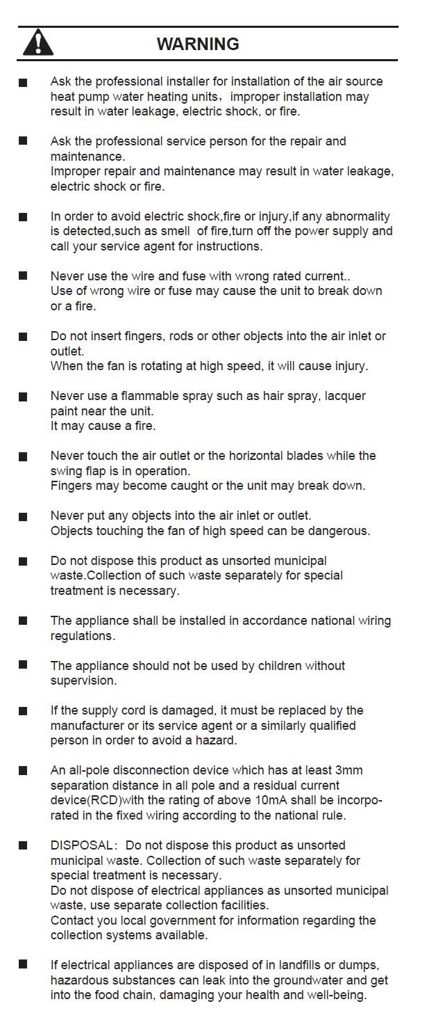
18 Electric connection The power supply should be an independent circuit with rated voltage. Power supply circuit should be earthed effectively. The wiring must be performed by professional technicians in accordance with national wiring regulations and the circuit diagram. An all-pole disconnection device which has at least 3mm separation distance in all pole and a residual current device (RCD) with the rating of above 10mA shall be incorporated in the fixed wiring according to the national rule. Set the electric leakage protector according to the relevant electric technical standards of the local. The power cord and the signal cord shall be laid out neatly and properly without mutual interference or contacting the connection pipe or valve. After wire connection, check it again and make sure the correctness before power on. Specifications of power supply Model name Power supply Calor Top 300D / Calor Top 300D(S) V~, 50Hz, 1 phase Min. diameter of power supply cord (mm 2 ) 4 Earth cord (mm 2 ) 4 Manual switch capacity (A)/Fuse (A) 40 / 30 Creepage breaker 30mA, 0.1sec Choosing the power cord according to above table, and it should comply with local electric standard. The power cord model, recommended power cord mode is H05RN-F. 18

19 PCB I/O Ports description Warning: SW1 and SW2: Factory settings are all OFF ; Is not allowed to alterate this settings 19
20 Solar energy coil electrical control instruction - CN26 is the terminal for solar input signal This terminal is used for receiving 230V feedback signal. If CN26 gets 230V feedback signal, CN2 will output control signal, to control solar pump; if CN26 have not gotten feedback signal, the solar pump will never turn on. And CN26 is connecting with VH-3 terminal. CN2 is the terminal for solar pump control This terminal utilizes the 230V control signal, to control solar pump. And this terminal is connecting with VH-3 terminal. Note: solar pump must be controlled through AC contactor. The CN2 is not allowed to drive the pump directly. CN17 is the ON/OFF terminal This terminal is used to receiving ON/OFF signal. When the signal close, the heat pump will never turn on. When the signal open, the heat pump will run well. And CN17 is connecting with VH-2 terminal. Heat pump installation guide for solar pipe For Calor Top 300D(S) model there are two routine guides for solar pipe installation. But the relevant parts should be provided by users. Guide 1:. When the pump station check the solar water temperature is OK, it will output 230V signal, when the CN26 get this signal, the heat pump CN2 will output 230V signal to drive the solar pump. 20
21 . When the heat pump check the temperature on the water box T5U 65, no matter whether CN26 get the signal or not, CN2 will never output 230V signal, solar pump can t work. Until water temperature turn down to T5U 60, the CN2 will make the solar pump work. Note: Usando If we use guide 1, when the solar pump work, the heat pump can also operate normally. Guide 2:. When the pump station check the temperature is OK in solar pipe, it will output 230V signal, and the CN26 will get this signal, then the CN2 will output 230V signal to control the contactor, the contactor will close, the solar pump will turn on. And the CN11 will check the ON/OFF signal; the heat pump will stop operating.. When the pump station check the temperature is not OK, it will stop output 230V signal, CN2 will also stop output 230V signal, the contactor open, solar pump will turn off. And the CN11 check the ON/OFF signal, the heat pump will operate.. When the heat pump check the water temperature on the water box T5U 65, no matter whether CN26 get the signal or not, the CN2 will not output 230V signal, solar pump can t work. Until the water temperature on the water box T5U 60, the CN2 will make the solar pump work. Note: If we use guide 2, when the solar pump work, the heat pump cannot operate. 23

22 2.9 Water affusion and effusion Water affusion: If the unit is used for the first time or used again after emptying the tank, please make sure that the tank is full of water before turning on the power. Caution: The Ball valve at water inlet should be open when the unit is in operation. Operation without water in water tank may result in damage of auxiliary e-heater. Due to such damage, the supplier is not responsible for the quality issue. Water effusion: If the unit needs cleaning, moving etc., the tank should be emptied. Note: The outlet water temperature maybe very high when emptying, beware of your body for burns. 22
23 2.10 Trial run Checking list before trial- running: Correct installation of the system. Correct connection of water/air piping and wiring. Condensate draining smoothly well insulation work for all hydraulic part. No obstacle outside the air inlet and outlet. Correct power supply. No air in the water pipeline and all valves opened. Effective electric leakage protector installation. Sufficient inlet water pressure, between 0.15MPa and 0.65MPa (1,5 atm ~ 6,4 atm). Water temperature display The temperature shown of the display depends on the upper sensor. It is normal that the display temperature has reached to target temperature but compressor still running, because the lower water temperature does not get to target temperature. Heat source shift The default heating source is heat pump. If the ambient is range out of heat pump, heat pump will stop running, and the unit will shift automatically to activate E-heater and show the icon LA on the display, then if the ambient temperature goes into the running range of heat pump again, it will stop E-heater and shift automatically to heat pump again, and the icon LA will be extinguished If the target setting water temperature is higher than the maximum temperature (Heat pump), the unit will activate heat pump firstly to the maximum temperature, then stop heat pump, activate E-heater to continually heat water to the target temperature. If manually activate the E-heater running mode when heat pump running, E-heater and heat pump will work together until the water temperature gets to target temperature. So if want to heat quickly, E-heater should be activated manually. E-heater will be activated once for the current heating progress, if want to apply E-heater again, the button of E-HEATER should be pressed once. Note: In the E-heat mode, only half tank of water, i.e. 150L, could be heat every time. How is the unit running? If unit is OFF, press and the unit will be waken, then press to set target water temperature(38~60 ),press and the unit will automatically select mode and start to heat water to target temperature. Note: If system occurs some malfunctions, error code E7 and will be shown on the display, then heat pump will stop running and the unit will activate automatically E-heater as the backup heat source, but the code E7 and will be shown until power off. 23

24 2.11 Maintenance Recommended regular maintenance table Checking item Checking content Checking frequency Action 1 Air filter (inlet/outlet) Every month Clean the filter. 2 Anode rod Every half year Replaced if it has been used out. 3 Inner tank Every half year Clean the tank. 4 E-heater Every half year Clean the E-heater. 5 PT valve Every year Operate the hander of PT valve to ensure that waterways are clear. If water dose not flow freely when operating the hander, replace PT vale with a new one. Check the connection between power supply plug and socket and ground wiring regularly. In some cold area (below 0 C), if the system will be stopped for a long time, all the water should be released in case of freezing of inner tank and damage of E-heater. It is recommended to clean the inner tank and e-heater regularly to keep an efficient performance. It is recommended to clean the inner tank and e-heater regularly to keep an efficient performance. It is recommended to set a lower temperature to decrease the heat release, prevent scale and save energy if the outlet water is sufficient. Clean the air filter every month in case of any effect on the heating performance Before shutting the system down for a long time, please: _ Shut down the power supply; _ Release all the water in water tank and the pipeline and close all the valves; _ Check the inner components regularly; Water outlet Upper tank temp. sensor Electric water heater Lower tank temp. sensor Solar coil Water inlet 24

25 Node rod replaced Turn off the power supply and water inlet valve. Open hot water tap, and decrease the pressure of the inner container. Open the drainage valve, and drain out the water, until there is no water flow out. Get off the anode rod. Replace with a new one, and make sure effective sealed. Open cold water inlet tap until water flows out from outlet tap, then turn off water outlet tap. Power on, and then restart the unit. PT Valve The handle of PT Valve should be pulled out once per half a year to make sure that there is no jam of the valve. Please beware of burn by hot water from the valve. The drainage pipe should be well insulated in order to prevent water inside pipe from freezing in cold weather Handle Drainage pipe Temperature Display When the system stops, a decrease of the temperature is normal as heat released. When it decreases to some point, the system will restart automatically. During water-heating, the displayed water temperature might still decrease or not increase for a period of time because of the heat exchange of the water. When the whole tank of water has reached the set temperature, the system will stop automatically. Cleaning filter Filter is inserted in the principal air inlet duct; Unscrew the air inlet ring in anti-clockwise sense; Remove filter and clean it completely; Reassemble it in the unit; Restart after Long Stop When the system is started after a long time (trial running included), it is normal if the outlet water is unclean. Keep the tap on and it will be clean soon Trouble shooting Error phenomenon Cause Resolutions Cold water tapped out and display screen extinguished No hot water tapped out Bad connection of power supply plug and socket; Setting outlet water temperature too low; Temperature sensor broken; PCB indicator broken; Public water supply ceased; Cold water inlet pressure is too low (<0.15MPa); Cold water inlet valve closed; Plug in; Setting water temperature higher; Contact service center. Waiting for public water supply recover; Waiting for inlet water pressure increase; Open water inlet valve; Water leakage Hydraulic pipeline joints are not sealed well; Check and reseal all the joints; If the unit occurs any malfunction or error, please shut down the system, turn off the power supply, and consult your service persons for help. 25
26 Malfunction and protection codes Code Content E0 E1 E2 E4 E5 E6 Error of sensor T5U. Error of sensor T5L. Tank and wired controller communication error. Evaporator temperature sensor T3 error. Ambient temperature sensor T4 error. Compressor discharge temperature sensor TP error. E8 E9 Electric leakage error (If the mutual inductor reveal a difference between L and N >14mA) Compressor suction temperature sensor TH error. EE E-heater open-circuit error ( Damaged resistance ) EF Ed Clock chip error. E-EPROM chip error. P1 P2 P3 P4 LA System high pressure protection (>2,76MPa (26,6 atm) ON, < 2,07MPa (20,4 atm) OFF) High discharge temperature protection (Tp>115 C ON, Tp<90 C OFF) No current flowing in compressor. Compressor overloaded protection. Ambient temperature is not fit for heat pumps; change the mode to E-heater. E0, E1 Note: T5U is the upper water temperature sensor. T5L is the lower water temperature sensor. 26
27 E2 E4, E5, E6, E9 E8 Note: T3 is the evaporator temperature sensor T4 is the ambient temperature sensor TP is the compressor discharge temperature sensor TH is the compressor suction temperature sensor Note: If the PCB current-induction-circuit check the current difference between L, N >14mA, system considers it as electric leakage error. 27

28 EE Note: E-heater open-circuit error means that IEH (Current difference E-heater on and off) <1A EF Note: When the EF code checked by query function is displayed, the unit can work well without clock-memory. It is needed to reset clock when power put on again. Ed If some normal error happen, unit will automatically shift to E-heater for emergent SHW supply; please contact qualified staff to repair. If some errors happen, the buzzer will buzz 3 times every other minute and the Press CANCEL for 1 sec to stop the buzzer, but the alarm icon will keep glittering. icon will flash fast. 28
29 2.13 Function Week disinfect Under disinfection mode, the unit will immediately start to heat water up to 65 C to kill the Legionella bacteria inside water tank. icon will light on the display screen during disinfection. Unit will quit disinfection mode if water temperature is higher than 65 C and extinguish the icon. Vacation function After pressing Vacation button, unit will automatically heat water to 15 C for the purpose of energy saving during vacation days. Query function For the convenience of maintenance and debug, query function is available by pressing 2 buttons together: E-HEATER + DISINFECT, then system running parameters will be shown one by one with following sequence by each pushing of UP or DOWN button No. Hour low bit Min. high bit Min. low bit Item Explanation 1 Temperature T5U 2 Temperature T5L 3 Temperature T3 4 Temperature T4 5 Temperature TP 6 Temperature Th 7 Current Compressor 8 Last error code 9 10 Previous 1st error or protection code Previous 2nd error or protection code 11 Software number TCO and ATCO The power of compressor and E-heater will be automatically switch on or switch off by TCO and ATCO. If the water temperature is higher than 78 C, the ATCO will automatically shut off the power of the compressor and E-heater, and turn it on if the temperature falls down below 68 C. If the water temperature is higher than 85 C, the TCO will automatically shut off the power of the compressor and E-heater, it should be re-turn manually. 29
30 2.14 Non-error tips Q: Why compressor can t start immediately after setting? A: Until will wait for 3 min. to balance the pressure of system before start compressor again; it s a self protection on unit. D: Why sometimes the temperature shown on the display panel decrease while unit is running? R: When the upper tank temperature is much higher than the bottom part, upper part of hot water will be mixed by the bottom cold water wich is continually flow from inlet tap water so that will decrease the upper part temperature. D: Why sometimes the temperature shown the display panel decrease but unit still keep closed? R: To avoid unit ON/OFF frequently, unit will activate heate source only when bottom tank temperature is lower than setting temperature for at least 5 C. D: Why sometimes the temperature shown the display panel decrease dramatically? R: Because tank is pressure-bearable type, if there is massive hot demand, hot water will quikly tapped out from upper part of tank as well as cold water will quikly tapped into bottom part of tank. If the cold water surface emerge the upper temperature sensor, temperature shown on the display will decreased dramatically. D: Why sometimes the temperature shown the display panel decrease a lot but there is still a mount of hot water that can be tapped? R: Because the upper water sensor is located on the upper ¼ of tank; when tapping hot water out, it means there is at least ¼ tank of hot water available. D: Why sometimes unit shows LA on display? R: The heat pump available running ambient range is -7 C ~ 43 C; if ambient temperature is out of range, system will show above mentioned signal to let user notice it. D: Why sometimes there is nothing shown on the display? R: To mantain display screen lifespan within along term, when there is no button operation for 30 sec. it will extinguish the display except LED indicator. D: Why sometimes the buttons are unavailable? R: If there is no operation on panel for 1 min. unit will lock the panel and shows ; to unlock the panel, please press ENTER button for 3 sec. D: Why sometimes there is some water flowed from drainage pipe of PT valve? R: Because the tank is pressure-bearable one; when water is heated inside the tank, water will expand, so the pressure inside of tank will increase. If pressure goes up more than 1 MPa, PT valve will activate to relief the pressure and hot water drop will be discharged correspondingly. If water drop is continually discharged from PT valve drainage pipe, it is abnormal; please contact qualified stuff to repair. Something about self-protection of unit When the self protection happens, the system will be stopped and start self-check and restart when the protection is resolved When the self protection happens, the buzzer will buzz in every other minute, the icon will flash and error code will be shown at water temperature indicator. Press CANCEL button for 1 sec. to stop buzz, but the icon and error code does not disappear until protection resolved. In the following circumstance, self-protection may happen: Air inlet or outlet is blocked, Evaporator is covered with too much dust or Incorret power supply (exceeding the range of V). 30
31 Defrosting function In the Economy Mode, if the evaporation frosts in a cold circumstance, the system will defrost automatically to keep effective performance (3~10 min). During defrosting, fan stops working, four-way valve reverses the flow direction, and compressor keeps working. _ Conditions to activate defrosting cycle: When T3 0, Compressor is continually running for 40 minutes. (If compressor restarts frequently, which can only run within 10 minutes. For each start cycle, system will count accumulated running time, when accumulated running time reaches 40 minutes defrosting cycle will activate 2 minutes after compressor s next start). _ Conditions to inactivate defrosting cycle: 1. Defrosting time reaches 10 minutes 2. T3 15 C _ Main components movement when defrosting Self-protection detection When the self-protection happens, the system will be stopped and start self-check, and restarts when the protection resolved; When the self-protection happens, the buzzer will buzz in every other minute, the Warning indicator glitter and the display indicate the error code and water temperature alternatively. Press CANCEL button for 3 seconds to stop the alarm. All stop when the protection is resolved and error code disappears on the display. In the following circumstances, self-protection starts: 1. Air inlet or outlet is obstacles; 2. The heat exchanger is covered with too much dust; 3. Incorrect power supply (exceeding the range of 220±10%); Note: When self-protection happens, cut the power supply manually and restart after the error resolved Auto-restart function If electricity power failed, unit can memorize all setting parameters, and unit will be back to the previous setting when power recovers. Button auto-lock When there is no operation of button for 1 minute, button except unlock button ( ENTER ) will be locked. Press ENTER for 3 seconds, unlock buttons. Screen auto-lock If there is no operation of button for 30 seconds, screen will be locked (extinguished) except for error code and alarm light. Press any button will unlock the screen (lighten) d31


32 2.15 Operation Display explanation 1. Wire controller If connected a wire controller, the icon will be lightened, otherwise, the icon be extinguished. 2. Outdoor solar heat source If an outside solar heat source has been connected to the unit, this icon will flash with 0.5Hz frequency, and otherwise, it will be extinguished. 3. Vacation mode The icon will be lightened if the unit is under vacation mode, otherwise the icon will be extinguished. When setting vacation mode, the icon will flash with 2Hz frequency. 32
33 4. Compressor The icon will be lightened when compressor is running, otherwise it will be extinguished. 5. E-heater The icon will be lightened if E-heater is activated, otherwise, it will be extinguished. If E-heater is automatically activated by unit, the icon will be lightened. If E-heater is manually activated, it will flash with 0.5Hz frequency. When setting E-heater manually ON/OFF, it will flash with 2Hz frequency. 6. Disinfect The icon will be lightened when the unit is under disinfecting mode, otherwise it will be extinguished. The icon will be lightened if disinfect mode is automatically activated by unit. The icon will flash with 0.5Hz frequency, if disinfect mode is manually activated. It will flash with 2Hz frequency when setting this mode or setting disinfect timer. 7. Allarme di alta temperatura If setting water temperature is higher than 50 C, the icon will be lightened, otherwise it will be extinguished. 8. Alarm When unit is under protection /error, the icon will flash with 5Hz frequency as well as buzzer will sound 3 times per minute until protection/error eliminated or press CANCEL for 1 second. 9. Lock If button is locked, the icon will be lightened, otherwise it will be extinguished. 10. Temperature unit If setting temperature unit as Celsius, C will be lightened, will show Celsius degree. If setting temperature unit as Fahrenheit, ºF will be lightened, will show Fahrenheit degree. 11. Invalid If button is under lock mode, press any button except unlock button, the icon will be lightened. 12. The icon will be lightened if screen is unlocked. It shows water temperature on normal mode. If on vacation mode, it shows remaining vacation days. Under setting mode, it shows setting temperature. If under query mode, it shows unit setting or running parameters, error or protection code. 13. Reserved 33

34 14.1 Water temperature setting The icon will be lightened when setting water temperature or setting days for vacation Date setting The icon will be lightened when setting days for vacation. If under vacation mode, the icon will be lightened. 15. Timer There are six timers can be set. If anyone of them has been set, the icon will lighten the corresponding one when screen is unlocked. If there is none of timers has been set, it will keep extinguished. If timer is being set, it will flash the corresponding one with 2Hz frequency as well lighten the timer which has been set. 16. Clock and clock setting The icon shows the clock. Whenever there is any setting for clock, will be lightened. Operation panel explanation Note: Any press of button is effective only under button and display unlocked state. E-heater Turn on E-heater manually. If E-heater is off, follow these steps below to manually turn it on. - Press E-HEATER, icon will flash. Press ENTER to confirm manually turning on E-heater, then E-heater is activated to heat up water to the target temperature. After that, if need manually turn on E-heater again, repeat these steps. If E-heater is already on, press E-HEATER will lead to show invalid icon on the display. Temperature unit shift Long pressing the E-HEATER key for 10 seconds then can shift to set the temperature display unit from F to C or from C to F. The default is C. When it is shifted to display F, it still will display C while it operates spot check. 34
 continuously. When setting clock/timer, through pressing INCREASE ( DECREASE ) more than 1 second, clock/timer value will be increased (decrease) continuously.")
35 INCREASE / UP & DECREASE/DOWN If screen is unlocked, corresponding value will increase by pushing or When setting temperature, by pressing INCREASE ( DECREASE ) more than 1 second, temperature value will be increase (decrease) continuously. When setting clock/timer, through pressing INCREASE ( DECREASE ) more than 1 second, clock/timer value will be increased (decrease) continuously. When setting vacation days, pressing INCREASE ( DECREASE ) more than 1 second, day value will be increased continuously. Under query mode, check items will page up by pressing INCREASE or page down by pressing DECREASE. CANCEL To cancel setting, quit setting, clear alarm, etc. And to clear alarm buzzer, need to press for 1 second. ON/OFF (With LED indicator) If unit is standby, press ON/OFF, then unit will be off. If unit is on, press it, and then unit will be off. If unit is off, press it, unit will be on. LED indicator will be lightened if unit is on or standby and extinguished if unit is off. ENTER (Include CONFIRM/UNLOCK) If screen and buttons are unlocked, press to upload setting parameters after setting any parameter. If press within 10 seconds, setting parameters will be uploaded to unit. If press beyond 10 seconds, all the parameters should be reset. If screen and buttons are locked, press it for 3 seconds to unlock them. DISINFECT Manually turn on disinfect function. Press DISINFECT button, the icon will flash. Press ENTER to confirm manually activate disinfection function. The unit will heat up water to 65 C at least for disinfection. Disinfect clock setting Press button DISINFECT for 3 seconds to enter disinfect clock setting. Then icon will flash, 35

36 and icon will be lightened and the hour value of clock will flash slowly. By pressing UP or DOWN, set the hour value of clock. Press CLOCK button to confirm the hour setting. Then the minute value of clock will flash slowly. By pressing UP or DOWN, set the minute value of clock. Press ENTER to confirm the disinfect clock setting and quit out. Note: Unit will automatically start disinfect function at the above-set clock every 7 days. If without disinfect clock setting, unit will automatically start disinfect function at 23:00 every 7 days. If unit is off or under disinfect mode, press DISINFECT will lead to show on the display.. VACATION In vacation mode, the setting target water temperature is 15 C as default and will show the remaining vacation days. On the last day of vacation, unit will automatically start disinfect function, and automatically reset the target temperature to the last one before vacation. If unit has already been under vacation mode or off, press the button of VACTION, then it will lead to show invalid icon on the display. Press VACATION button to enter vacation setting. Icon will flash. Icon will be lightened. Icon DAY will show the last setting vacation days. By pressing UP or DOWN, set vacation days. The day s range is 1~99 days, default as 14 days. Press ENTER to confirm vacation setting and quit out. The unit will immediately go into vacation mode. Setting clock Press button CLOCK for 3 seconds to enter clock setting. Then icon will be lightened and the hour value of clock will flash slowly. Press button UP or DOWN to set the hour value of clock. Press CLOCK to confirm the hour setting. Then the minute value of clock will flash slowly. Press UP or DOWN to set the minute value of clock. Press button ENTER, confirm the minute setting and quit clock setting. 36

 of the timer.")

37 Setting timer Press CLOCK to enter timer setting. Push UP or DOWN, select timer ( 1~ 6) which needs to be set. The timer icon will flash slowly if it is selected. Press CLOCK, and confirm the selected setting timer. Then Then the hour value of timer will flash slowly. By pressing UP or DOWN to set the hour value of timer. will be lightened. Pressing CLOCK to confirm the hour value of timer. Then the minute value of timer will flash slowly. By pressing UP or DOWN to set the minute value of timer. Pressing CLOCK, and confirm the minute value of timer. Then ON or OFF icon following the setting timer will flash slowly. By pressing UP or DOWN to set the action (on or off) of the timer. Push CLOCK, and confirm the action (on or off) of the timer. The display screen will automatically display different value at by different action. It will display the last set temperature and icon SET if the action is on, and will display --. If the action is off, by pressing ENTER, the setting timer will be exited. Cancel timer Press CLOCK to enter timer setting. By pressing UP or DOWN, select timer ( 1~ 6) which needs to be cancel. The timer icon will flash slowly it is selected. Check timer Press CLOCK to enter timer setting. By pressing UP or DOWN to select time ( 1~ 6) which needs to be checked. The timer icon will flash slowly if it is selected, and the timer action (on or off) and set clock will be shown. If the action is on, target temperature will be shown. And if the action is off, icon -- will be shown. 37
38 Press button CANCEL for 3 seconds or no button pressing for 30 seconds to quit timer checking. Note: If there is confliction between Timer and Manually-on: 1. The moment of Manually-on has priority. 2. The moment of Timer-off has priority. Clear error code Press ENTER and CLOCK at the same time to clear all stored error and protection codes. - The buzzer will buzz one time. Query mode Press E-HEATER and DISINFECT at the same time for 1 second to go into query mode. Under query mode, by pressing UP or DOWN, unit running and setting parameters can be checked. Press button CANCEL for 1 second or no button operation for 30 seconds, then quit query mode Accessories Name Qty. Sharp Purpose Owner s and Installation Manual 1 Installation and use instruction. One way valve 1 Prevent water from flowing backwards Drain pipe for water condensation 1 Discharge condensate water 38

39 2.17 Exploded view 39
40 40 N Part Name Qty Code N Part Name Qty Code 1 The wind ring Deck board Filter Upper heater cover Net Deck magnet Front casing Magnet clip Up cover Magnet cover Magnesium rod plug way valve ass'y Junction box cover Pipe joint Motor way valve Display panel Solenoid Display board ass'y Electronic expansion valve ass'y Centrifugal fan EEV solenoid Display cover E-Part box cover Tank foam components (Calor Top 300D(S) model) 1 Tank cover assembly ( ) 14.2 Froth plug Temp sensor Solenoid valve winding Electronic expansion valve Solenoid valve Compressor Discharge temp sensor ass'y Room temp sensor ass'y Magnesium anode Temp.sensor ass'y Thermometer Temperature sensor Stator of temp. sensor Temp.sensor ass'y Water electric 14.7 heating Temp.sensor ass'y seal ring of radiation Compressor electric pipe heater Seal Stopper Evaporator ass'y Drain plug assembly Evaporator Tank bottom cover Evaporator output pipe ass'y Evaporator input PT valve loop pipe ass'y Junction Bbox Water tank handle components Temperature and pressure safety Connection bracket valve 15 Magnet frame Wire joint, 3p E-part box ass'y Front shell E-part box Compressor wire joint ass'y Compressor 16.2 capacitor Screw plate Main control board ass'y Rear shell Transformer Drain Motor capacitor Rear casing Wire joint Dry filter Relay Plumbing fixture Electronic control box bracket


41 2.18 Typical applications in cooling and purification of air With duct connection or without it Without duct connection In case of a closed room with internal heat sources, the unit can work optimally without the need to ducting, sucking hot air and putting cooled and dehumidified air in the room. Suitable premises for installation without ducting: - laundry / drying room; - unheated rooms; - unheated rooms; - technical rooms; - rooms without internal loads but with openings for air circulation; With internal heat sources Cold air outlet Hot air inlet Without internal heat sources Cold air outlet Hot air inlet 41


42 In a room without internal heat sources, for a correct operation of the machine is necessary to ensure some ventilation to prevent the excessive decreases of internal temperature. With duct connection In case of a closed room, without air exchange and without internal heat loads, use of ducts is necessary to avoid excessive cooling of the room, and then a malfunction of the unit. - Hot air extraction With air duct is possible to extract hot air from a room with thermal loads and put it externally. In this way the unit works with high performance and extracts heat from a with thermal loads. - Dehumidification and air exchange With air ducts the unit can suck hot air from the outside and carry it cooled and dehumidified in a certain room, ensuring the exchange of air. 42


43 - Dehumidification and cooling With air ducts it is possible to suck hot air from a room with thermal loads and re-insert it cooled and dehumidified. - Without any environmental impact With air ducts it is possible to install the unit inside a closed room without alterate the internal temperature, sucking air from outward and carry it out. 43
44 2.19 Running Logic Parameters: T4 ambient temperature Tstop Max. water temperature which heat pump can reach in accordingly T4 Ts setting (desired) water temperature T5U UP water tank temp T5L LOW water tank temp HEAT PUMP 1) When in below conditions, the heat pump start (only compressor): a) T5L < min(ts-10 C ; Tstop-10 C) or b) T5L < 35 C or c) T5U < min(ts-5 C ; Tstop-5 C) Example : case a i) Ts = 50 C and T4 = 3 C then Tstop = 55 C T5L < min (40 ; 45) T5L < 40 C Water is heated only by Heat Pump, until T5L reaches the desired temperature (50 C) ii) Ts = 50 C and T4 = - 3 C then Tstop = 42 C T5L < min (40 ; 32) T5L < 32 C 44 N.B. Heat pump start at 35 C however (case b). Water is heated only by Heat Pump, until T5L reaches the stop- temperature (42 C). Now heat pump stops and the unit automatically activates the resistance E-heater to reach the desired temperature (50 C)
45 case c i) Ts = 50 C and T4 = 3 C than Tstop = 55 C T5U < min (45 ; 50) T5U < 45 C Water is heated only by Heat Pump, until T5L reaches the desired temperature (50 C) ii) : Ts = 50 C and T4 = -3 C than Tstop = 42 C T5U < min (45 ; 37) T5U < 37 C Water is heated only by Heat Pump, until T5L reaches the stop-temperature (42 C). Now heat pump stops and the unit automatically activates the resistance E-heater to reach the desired temperature (50 C). 2) When in below condition, the the heat pump stop: Example : T5L min (Ts ; Tstop) i) : Ts = 50 C and T4 = 3 C then Tstop = 55 C T5L min (50 ; 55) T5L 50 C 45
46 RESISTANCE E-HEATER 3) E-heater mode (only electrical resistance) is automatically activated in following conditions: a) When -7 C < T4 < 45 C: If Ts > Tstop (when T5L=Tstop, heat pump stops, and if T5U < (Ts-1 C), heat pump turn into E-heater mode) Example: i) Ts = 50 C and T4 = 3 C then Tstop = 55 C Ts > Tstop? NO Water is heated only by Heat Pump, until T5L reaches the desired temperature (50 C). Electrical resistance is not necessary! ii) Ts = 50 C e T4 = -3 C quindi Tstop = 42 C Ts > Tstop? YES When T5L = 42 C Heat Pump stop running, and if T5U < 49 C resistance automatically start, until T5L reaches the desired temperature (50 C) If T4 < 5 C (After Heat Pump has worked for 6 hours, and T5U < 35 C, then the unit switch on E-heater mode (working together with Heat Pump) b) When T4 > 45 C or T4 < -7 C When the water temperature sensor T5U < Max (Ts-10 C ; 35 C) E-heater mode start working. Example: Ts = 50 C T5U < Max (40 ; 35) T5U < 40 C 4) E-heater mode automatically stop working in following condition: When T5U Ts-1 C Example: Ts = 50 C T5U 49 C 46
HEAT PUMP WATER HEATER
 SERVICE MANUAL HEAT PUMP WATER HEATER SWH-15/190TL SWH-35/300TL,SWH-35/300TSL Sanitary Water Heater Technical Manual Sanitary Water Heater Technical Manual Applicable Model: SWH-15/190TL SWH-35/300TL SWH-35/300TSL
Installation, Service and User Manual DTW 300 SP
 Installation, Service and User Manual DTW 300 SP VMGFK202 If these instructions are not followed during installation and service, Danfoss A/S liability according to the applicable warranty is not binding.
WATER HEATER INSTALLATION & USER'S MANUAL. Model HWMI 300 A WARNING! PLEASE READ CAREFULLY THIS MANUAL BEFORE INSTALLING THE WATER HEATER - 1 -
 WATER HEATER INSTALLATION & USER'S MANUAL Model HWMI 300 A WARNING! PLEASE READ CAREFULLY THIS MANUAL BEFORE INSTALLING THE WATER HEATER - 1 - TERMAL S.R.L. Via della Salute, 14 -- 40132 -- Bologna --
WATER HEATER INSTALLATION & USER'S MANUAL. Models HWMI 150 A HWMI 190 A WARNING! PLEASE READ CAREFULLY THIS MANUAL BEFORE INSTALLING THE WATER HEATER
 WATER HEATER INSTALLATION & USER'S MANUAL Models HWMI 150 A HWMI 190 A WARNING! PLEASE READ CAREFULLY THIS MANUAL BEFORE INSTALLING THE WATER HEATER - 1 - TERMAL S.R.L. Via della Salute, 14 -- 40132 --
Installation & Owner s Manual ALL IN ONE Type Air-source Heat Pump Water Heater EcoSpring ES190
 Installation & Owner s Manual ALL IN ONE Type Air-source Heat Pump Water Heater EcoSpring ES190 Thank you very much for purchasing our product, Before using your unit, please read this manual carefully
Installation & Owner s Manual ALL IN ONE Type Air-source Heat Pump Water Heater EcoSpring ES300
 Installation & Owner s Manual ALL IN ONE Type Air-source Heat Pump Water Heater EcoSpring ES300 Thank you very much for purchasing our product, Before using your unit, please read this manual carefully
Heat Pump Water Heater Technical Manual
 ALL IN ONE Type Heat Pump Water Heater Technical Manual Applicable Models: RSJ-15/150RDN3 RSJ-15/190RDN3 EcoSpring reserves the right to discontinue, or change at any time, specifications or designs without
Midea R410A Domestic Pools & Spas Heat Pump Water Heater 50Hz A1 Series Technical Manual
 Midea R410A Domestic Pools & Spas HPWH 50Hz Technical Manual MCAC-HTSM-201409 Midea R410A Domestic Pools & Spas Heat Pump Water Heater 50Hz A1 Series Technical Manual Applicable Model: (New CE safety directive)
INSTALLATION & OWNER S MANUAL
 INSTALLATION & OWNER S MANUAL ALL IN ONE Type Air-source Heat Pump Water Heater Thank you very much for purchasing our product, Before using your unit, please read this manual carefully and keep it for
USER'S MANUAL SWH-35/300TL2
 USER'S MANUAL WATER HEATER SWH-3/300TL2 HEAT P U M P S Original instructions IMPORTANT NOTE: Read this manual carefully before installing or operating your new air conditioning unit. Make sure to save
Floor-Standing Type(E Series)
") Floor-Standing Type(E Series) Model: MFE-60CE, MFE-60AE Part 1. Product Features With a spiral shape, the computer-aided simulation designed air passage system can efficiently reduce noise. The Soft touch
Floor-Standing Type(E Series) Model: MFE-60CE, MFE-60AE Part 1. Product Features With a spiral shape, the computer-aided simulation designed air passage system can efficiently reduce noise. The Soft touch
INSTALLATION AND USER MANUAL
 INSTALLATION AND USER MANUAL Thank you for choosing our product and trusting our company. This manual is to provide you with necessary information for optimal use and maintenance, please read carefully
Ceiling & Floor type Unit
 Ceiling & Floor type Unit Part 1. Product Features Quietest operation, low noise. Thin design, space-saving. Easy to operate, remote control. 16 Part 2. Specification Model MUA-18HRN2 MUA-24HRN2 MUA-24HRN2
Contents. Part 1 General Information...2 Part 2 Outdoor units...7 Part 3 Installation...63 Part 4 Controller...79
 MCAC-TSM-2008-02 Contents Part 1 General Information...2 Part 2 Outdoor units...7 Part 3 Installation...63 Part 4 Controller...79 Contents i MCAC-TSM-2008-02 Introduction Introduction Midea Mini Unitary
Warning: 230V / 1ph / 50Hz V / 3ph / 50Hz. Remarks: Make sure that you have enough power. (See page 15 Cable table)
") 1 2 Warning: - Do not place your hand or any other objects into the air outlet and fan. It could damage the heat pump and cause injuries; - In case of any abnormality with the heat pump, cut off the power
1 2 Warning: - Do not place your hand or any other objects into the air outlet and fan. It could damage the heat pump and cause injuries; - In case of any abnormality with the heat pump, cut off the power
INSTALLATION AND USER MANUAL
 INSTALLATION AND USER MANUAL Thank you for choosing inverter heat pump. This manual provides you necessary information for optimal use and maintenance, please read it carefully and keep it for subsequent
INSTALLATION AND USER MANUAL
 INSTALLATION AND USER MANUAL t Thank you for choosing Aqua inverter heat pump. This manual provides you necessary information for optimal use and maintenance, please read it carefully and keep it for subsequent
THROUGH-WALL AIR-TO-AIR HEAT PUMP AND AIR CONDITIONER. Instruction Manual. Model AMB-12H
 THROUGH-WALL AIR-TO-AIR HEAT PUMP AND AIR CONDITIONER Instruction Manual Model AMB-12H PLEASE READ THIS INSTRUCTION MANUAL CAREFULLY BEFORE USING THIS UNIT. Table of Contents 1. SAFETY WARNINGS 2 2. CONSTRUCTION...
15,000 BTU Portable Air Conditioner
 Instruction Manual 15,000 BTU Portable Air Conditioner Model: HYAC15 READ AND SAVE THESE INSTRUCTIONS Please read and follow the instructions in this user manual even if you feel you are familiar with
C&H NORDIC Commercial 4 SERVICE MANUAL
 C&H NORDIC Commercial 4 SERVICE MANUAL CONTENTS PRODUCT...3 1 MODELS LIST... 3 1.1 Outdoor Unit.... 3 1.2 Indoor Unit.... 4 2 PRODUCT DATA.... 5 2.1 Product Data of Indoor Unit... 5 2.2 Operation Range...
Technical Manual. R410A 50Hz Universal Outdoor Series Inverter type. R410A50Hz Universal Outdoor Series Technical Manual LCAC/2016.
 Outdoor Unit R410A 50Hz Universal Outdoor Series Inverter type Technical Manual LCAC/2016.1 I GD Chigo Heating & Ventilation Equipment Co., Ltd. Content Part 1. General Information... 1 1. Nomenclature...
Part 1 General Information... 1 Part 2 Outdoor Unit... 4 Part 3 Installation... 45
 Contents Part 1 General Information... 1 Part 2 Outdoor Unit... 4 Part 3 Installation... 45 The specifications, designs, and information in this book are subject to change without notice for product improvement.
Service manual. MIV V4+ Mini
 DM12-01.01.05en Service manual MIV V4+ Mini DC INVERTER R410A (~220V, 50Hz, 1Ph) MVUH80A-VA1 Contents Part 1 General Information... 1 Part 2 Outdoor Units... 6 Part 3 Installation... 44 DM12-01.01.05en
TAC-09CS/K TAC-12CS/K TAC-18CS/K TAC-24CS/K TAC-07CHS/K TAC-09CHS/K TAC-12CHS/K TAC-18CHS/K TAC-24CHS/K
 TCL WALL MOUNTED SPLIT-TYPE AIR CONDITIONERS SERVICE MANUAL No.TE040427 Models TAC-07CS/K TAC-09CS/K TAC-2CS/K TAC-8CS/K TAC-24CS/K TAC-07CHS/K TAC-09CHS/K TAC-2CHS/K TAC-8CHS/K TAC-24CHS/K CONTENTS. IMPORTANT
UCV CONDENSING UNITS SPECIFICATIONS 1. Specifications
 UCV CONDENSING UNITS SPECIFICATIONS 1. Specifications Model UCV-76C UCV-96C Code 220075900040 220075900020 Power supply V- Ph-Hz 380-415~3~50 Capacity Btu/h 76000 96000 Cooling Input W 8100 10000 Rated
Service Manual & Installation Manual
 GE Consumer & Industrial Appliances Service Manual & Installation Manual Split System Air Conditioner Model numbers: GE AIR F24 GE AIR F34 GE AIR F41 1 2 3 Introduction and Features Model Remarks GE AIR
Inverter Swimming Pool Heat Pump
 P Inverter Swimming Pool Heat Pump Content I. Application... 2 II. Features... 2 III. Technical Parameter... 3 IV. Dimension... 4 V. Installation instruction... 5 VI. Operation instruction... 9 VII. Testing...
Service Manual. Multi Split Type Heat Pump Air Conditioners. Applied to: HS-9U2IM_HOS-18U2IM HS-9U11IM_HS-12U11IM_HOS-21U11IM
 Service Manual Multi Split Type Heat Pump Air Conditioners Applied to: HS-9U2IM_HOS-18U2IM HS-9U11IM_HS-12U11IM_HOS-21U11IM CONTENT 1. Product features 2. Specification 3. Dimensions 4. Refrigeration cycle
CLIM9000CE PORTABLE AIR CONDITIONER USER MANUAL
 CLIM9000CE PORTABLE AIR CONDITIONER USER MANUAL Please read this user manual before using this innovative Air Conditioner and keep it safe for future reference. SAFETY INSTRUCTIONS Important! Carefully
Content. The specifications, designs, and information in this book are subject to change without notice for product improvement.
 MCAC-ATSM-2014-01 Content R410A Mini Split Chiller 50Hz 1. Model Names of Outdoor Units... 2 2. External Appearance... 2 3. menclature... 3 4. Features... 4 5. Descriptions of Standard Unit... 6 6. Specifications...
Part 1 General Information... 1 Part 2 Indoor Units... 7 Part 3 Outdoor Units Part 4 Installation Part 5 Control...
 MCAC-UTSM-2008-11 Contents Part 1 General Information... 1 Part 2 Indoor Units... 7 Part 3 Outdoor Units... 88 Part 4 Installation... 127 Part 5 Control... 136 The specifications, designs, and information
Wired controller KJR-08B/BE. Run. Fault. TB Tot. Out. Query. Heat. Net-On. Turn-On Mode
 R0A (kw-0kw) 0Hz KJR-0B/BE is a human-machine interaction(hmi) used for the communication between chiller operator and main board on the chiller itself. The setting and operation order can be send to the
PDA20DX Air Purifying Dehumdifier Manual
 PDA20DX Air Purifying Dehumdifier Manual Index Important Safe Guards Ambient Environment For Operating Components Diagrams---Parts Names Operating Introduction---How to operate - Functions of Control Panel
Part 5. Troubleshooting. 1. Normal Air Conditioner Phenomenon Air Conditioner Protection in Common
 Part 5 1. Normal Air Conditioner Phenomenon... 1611 2. Air Conditioner Protection in Common... 1611 3. Malfunction Code and... 162 160 1. Normal Air Conditioner Phenomenon 1.1 When outdoor unit appears
INSTALLATION AND USER MANUAL
 Swimming Pool Heat Pump Swimming Pool Heat Pump INSTALLATION AND USER MANUAL Thank you for choosing our product and trusting our company. This manual is to provide you with necessary information for optimal
SERVICE MANUAL CONDENSING UNIT ASE-18AH, ASE-24AH, ASE-36AH, ASE-48AH, ASE-60AH
 SERVICE MANUAL CONDENSING UNIT ASE-18AH, ASE-24AH, ASE-36AH, ASE-48AH, ASE-60AH Outdoor Units - appearance 18,000Btu/h 30,000~36,000Btu/h 24,000Btu/h 48,000Btu/h-60,000Btu/h Model Names of Outdoor Units
CONTROL PANEL INSTRUCTIONS RSQ-4
 CONTROL PANEL INSTRUCTIONS RSQ-4 FOR SIRAC AIR TO WATER HEAT PUMP (SINGLE COMPRESSOR, AIR TO WATER) 1) System Configuration This system is composed of mainboard and wire control panel. 146mm Φ4 4 Mainboard
SILENT 12 PORTABLE AIR CONDITIONER USER MANUAL
 SILENT 12 PORTABLE AIR CONDITIONER USER MANUAL Thank you for choosing ElectriQ Please read this user manual before using this innovative Air Conditioner and keep it safe for future reference. Visit our
Wired Controller XK60
 Owner's Manual Commercial Air Conditioners Thank you for choosing Commercial Air Conditioners, please read this owner s manual carefully before operation and retain it for future reference. User Notice
Midea R410A Tropical ClimaCreator Series Rooftop Package 220V 3Ph 60Hz Technical Manual
 Midea R410A Tropical ClimaCreator Series Rooftop Package 220V 3Ph 60Hz Technical Manual Midea reserves the right to discontinue, or change specification or designs at any time without notices and without
USER MANUAL SILENT16 PORTABLE AIR CONDITIONER
 USER MANUAL SILENT16 PORTABLE AIR CONDITIONER Thank you for choosing electriq Please read this user manual before using this innovative Air Conditioner and keep it safe for future reference. Visit our
MANUAL DE INGENIERIA. Part 1 General Information... 1 Part 2 Indoor Units... 6 Part 3 Outdoor Units... 30
 MANUAL DE INGENIERIA Evaporadora Sopladora 'MVA' con Condensadora 'MOV' - Blue Star Part 1 General Information... 1 Part 2 Indoor Units... 6 Part 3 Outdoor Units... 30 Part 1 General Information 1. Model
DUCTED AIR CONDITIONER. Owner s Manual. KD Series KD24. Kaden Owner s Manual 1
 DUCTED AIR CONDITIONER Owner s Manual KD Series KD24 Kaden Owner s Manual 1 Table of Contents 1. Safety Precautions 4 2. Indoor Unit Parts and Major Functions 6 3. Care and Maintenance 8 4. Troubleshooting
[U] Serie MOV. Manual de Ingeniería
![[U] Serie MOV. Manual de Ingeniería](/thumbs/82/86228730.jpg "[U] Serie MOV. Manual de Ingeniería") [U] Serie MOV Uniidades Condensadoras (Fllujjo Verttiicall) 6..3,, 8 y 12..5 Ton Manual de Ingeniería - 112- Outdoor Units_MOV 1. Specifications.... 2. Dimension... 3. Service Space. 4. Piping Diagrams
[U] Serie MOV Uniidades Condensadoras (Fllujjo Verttiicall) 6..3,, 8 y 12..5 Ton Manual de Ingeniería - 112- Outdoor Units_MOV 1. Specifications.... 2. Dimension... 3. Service Space. 4. Piping Diagrams
Service Manual & Installation Manual
 GE Consumer & Industrial Appliances Service Manual & Installation Manual Split System Air Conditioner Model numbers: GE AIR C18 GE AIR C24 GE AIR C34 GE AIR C41 1 Introduction and Features Model Remarks
SPLIT TYPE AIR CONDITIONER WAS-09HSTD WINTAIR
 SPLIT TYPE AIR CONDITIONER SERVICE MANUAL WAS-09HSTD WINTAIR Type of contents 1. OPERATION RANGE 2. SPECIFICATION 3. INSTALLATION 4. REFRIGERANT FLOW DIAGRAM 5. ELECTRICAL DATA 6. CONTROL MODE 7. TROUBLE
Chiltrix 5.1 Thin DC - Inverter Water Fan Coil Unit Floor, Wall or Ceiling Universal Mount Manual
 Chiltrix 5.1 Thin DC - Inverter Water Fan Coil Unit Floor, Wall or Ceiling Universal Mount Manual Version 1.5 1 CONTENTS CHAPTER 1 GENERAL INTRODUCTION...3 1. Preface... 3 2. Product Introduction... 3
Installation and Operating Manual
 Installation and Operating Manual SR868C6 System Regulator for Solar Thermal Systems Display Panel Illustration Pos. Button on display panel Button description 1 Green lamp Power indication lamp 2 On/Off
Table of Contents. Notice: Any maintenance should be returned to the dealer or factory! Attention: Please read this instruction carefully before use.
 English Table of Contents 1. Accessories ------------------------------------------------------------------------1 2. Introduction--------------------------------------------------------------------------2
Service Manual. Air Conditional
 Air Conditional Service Manual Большая библиотека технической документации http://splitoff.ru/tehn-doc.html каталоги, инструкции, сервисные мануалы, схемы. -2 - MODEL: AC-FR30CM -3 - CONTENTS SPECIFICATION...
CASSETTE, FLOOR&CEILING, DUCT UNITS OUTDOOR UNITS
 SERVICE MANUAL MULTI COMBI OUTDOOR AND INDOOR UNITS CASSETTE, FLOOR&CEILING, DUCT UNITS OUTDOOR UNITS (36k,42k) COMBINATION TABLE (unit: kw) MC-E18AI MC-E24AI MC-E28AI MC-E36AI 1 model 2 models 2 models
MINI CHILLER INVERTER H4 Service manual MUENR-H4 (5, 7, 10, 12, 14, 16 kw)
") MINI CHILLER INVERTER H4 Service manual MUENR-H4 (5, 7, 10, 12, 14, 16 kw) CL25610 to CL25615 English Content 1. Outdoor units lineup... 2 2. Nomenclature... 3 3.Features... 4 4. Description of main components...
MINI CHILLER INVERTER H4 Service manual MUENR-H4 (5, 7, 10, 12, 14, 16 kw) CL25610 to CL25615 English Content 1. Outdoor units lineup... 2 2. Nomenclature... 3 3.Features... 4 4. Description of main components...
Window Y9USC/E 09 / 12 / 18 B5R
 Window Y9USC/E 09 / 12 / 18 B5R SERVICE MANUAL Y9USC-09 B5R; Y9USE-09 B5R Y9USC-12 B5R; Y9USE-12 B5R Y9USC-18 B5R; Y9USE-18 B5R SM-Y9USC-E-09-18GB 03-07 1. Precaution... 2 1.1 safety Precaution... 2 1.2
Technicians Manual Single Compressor
 Technicians Manual Single Compressor HAC-FF-D WALL PAD Operating Manual Version PCB Version V2.3.5 Version wall pad Version Manual Page 1 Contents 1. Main features 2. Main technical data 3. Wall pad 4.
Portable Air-conditioner
 Use and Care Manual Portable Air-conditioner Thank you very much for selecting this new model of Portable Air Conditioner, please read this Use and Care Manual carefully before installing and using this
USER MANUAL SILENT12 PORTABLE AIR CONDITIONER
 USER MANUAL SILENT12 PORTABLE AIR CONDITIONER Thank you for choosing electriq Please read this user manual before using this innovative Air Conditioner and keep it safe for future reference. Visit our
Air Cooled Scroll Chiller
 Air Cooled Scroll Chiller Midea chillers use H shape heat at air side and single unit s capacity from kw to 0kW. Super chillers are divided to SS,SS-LA, SP-LA and SP-HMLA series according to their water
3 In 1 AIR CONDITIONER with REMOTE CONTROL MODEL NO: CA9000 PART No: OPERATION & MAINTENANCE INSTRUCTIONS
 3 In 1 AIR CONDITIONER with REMOTE CONTROL MODEL NO: CA9000 PART No: 32305600 OPERATION & MAINTENANCE INSTRUCTIONS 0304 Parts List Item Part No Description Qty 1 FT900001 Top Cover 1 2 FT900002 Filter
MS7 Single Zone Mini Split System Air Conditioners and Heat Pumps
 2011 Lennox Industries Inc. Dallas, Texas, USA 506789 01 08/2011 MS7 Single Zone Mini Split System Air Conditioners and Heat Pumps This manual is the property of the homeowner and must be left with the
Portable Air Conditioner USER MANUAL
 AC12 AC12HP Portable Air Conditioner USER MANUAL Thank you for choosing this innovative Amcor air conditioner. We suggest that you keep this manual in a safe place for future reference. It describes the
Introduction Part 1 : General Information Part 2: Indoor Units Part 3: Installation Part 4: Control
 Introduction Part 1 : General Information Part 2: Indoor Units Part 3: Installation Part 4: Control i Introduction Fan coil unit is a kind of compound device which assemble fan and surface-type coil heating-exchanger
DC INVERTER MULTI-SYSTEM AIR CONDITIONER
 TECHNICAL & SERVICE MANUAL OUTDOOR UNIT : CU-3KE19NBU CU-4KE24NBU CU-4KE31NBU DC INVERTER MULTI-SYSTEM AIR CONDITIONER Capacity at 0V 19,100 BTU/h,200 BTU/h 30,600 BTU/h Outdoor Model No. CU-3KE19NBU CU-4KE24NBU
R22 air-cooled modular chiller 50Hz unit. Content
 Content 1.Nomenclature... 2 2.Product Schedule... 2. External Appearance... 4.Features... 4 5.Specification... 6 6.Dimension... 10 7.Refrigeration System Sketch Drawing... 14 8.Wiring Diagrams... 16 9.Electric
R410A50Hz Universal Outdoor Series Technical Manual
 Outdoor Unit R410A 50Hz Universal Outdoor Series Technical Manual 2013 Version LCAC/2.0/201308 I GD Chigo Heating & Ventilation Equipment Co., Ltd. Content Content PART 1.General Information... 1 1.Nomenclature...
Hi - Wall Split Systems. Super Quiet. Auto. Mode. Wireless Control. Smart Airflow ECO ECO. Function SLEEP. Vertical Auto Swing.
 R407C 220-240V ~, 50Hz Hi - Wall Split Systems Technology Tropical Compressor Super Quiet Auto Mode Auto Restart Easy Flexible Installation IAQ Anti-dust Filters AMS AMS Wireless Control Independent Dehumidification
MODEL: CCT 301 INV CCT 501 INV CCT 70 INV-S CCT 100 INV-S CCT 140 INV-S CCT 170 INV-S
 MODEL: CCT 301 INV CCT 501 INV CCT 70 INV-S CCT 100 INV-S CCT 140 INV-S CCT 170 INV-S Compact Four-way Cassette Type 1. Features... 2. Specification... 3. Dimension... 4. Service Space... 5. Wiring Diagram...
Dehumidifier. Instruction Manual. Model DH-320/A
 Dehumidifier Instruction Manual Model DH-320/A CONTENTS Safety Warnings 2 Operation consideration 5 Construction & controls 6 Function selection 8 Preparation for use 10 Operation 12 Maintenance 14 Continuous
AIR TO WATER HEAT PUMP USER MANUAL
 AIR TO WATER HEAT PUMP Domestic Hot Water Series USER MANUAL Installation Operation Maintenance MODELS: AKRS-35B/N-L AKRS-50B/N-L AKRS-7B/N-L AKRS-90B/N-L READ AND SAVE THIS MANUAL V.01304 CONTENTS 1.
Air Conditioner CONTENTS
 ORDER NO. MAC0509068C2 Air Conditioner CS-F24DD1E5 CU-B24DBE5 CS-F28DD1E5 CU-B28DBE5 CS-F28DD1E5 CU-B28DBE8 CS-F34DD1E5 CU-B34DBE5 CS-F34DD1E5 CU-B34DBE8 CS-F43DD1E5 CU-B43DBE8 CS-F50DD1E5 CU-B50DBE8 CONTENTS
COMPACT PORTABLE AIR CONDITIONER USER MANUAL
 COMPACT PORTABLE AIR CONDITIONER USER MANUAL Thank you for choosing ElectriQ Please read this user manual before using this innovative Air Conditioner and keep it safe for future reference. Visit our page
X-POWER Full DC Inverter Outdoor Unit
 OWNER'S MANUAL X-POWER Full DC Inverter Outdoor Unit Thank you very much for purchasing our air conditioner, Before using your air conditioner, please read this manual carefully and keep it for future
SERVICE INSTRUCTION R410A. SPLIT TYPE ROOM AIR CONDITIONER Cassette type Duct type Ceiling type INVERTER AO* G45LETL AO* G54LETL
 SPLIT TYPE ROOM AIR CONDITIONER Cassette type Duct type Ceiling type INVERTER SERVICE INSTRUCTION Models Indoor unit AU* G45LRLA AR* G45LMLA AR* G45LHTA AB* G45LRTA Outdoor unit AO* G45LETL AO* G54LETL
User instructions DHP-AT
 User instructions DHP-AT VUGFC202 If these instructions are not followed during installation and service, Danfoss A/S liability according to the applicable warranty is not binding. Danfoss A/S retains
1 Summary and features. Service Manual. Model QSVMI-09A QSVMI-12A QSVMI-18A
 Summary and features Service Manual Model QSVMI-09A QSVMI-2A QSVMI-8A 2 Technical specifications Model QSVMI-09A QSVMI-2A QSVMI-8A Fan Motor Speed (r/min) (SH/H/M/L) 50/050/900/750 50/050/900/750 250/050/950/800
Air source heat pump. (water heating module-18kw)
") Air source heat pump (water heating module-8kw) User Manual Before use Safety precautions 2 Features and advantages 3 Main components 4 Outlines and dimensions 5 Working principles 6 Technical data 7
Air source heat pump (water heating module-8kw) User Manual Before use Safety precautions 2 Features and advantages 3 Main components 4 Outlines and dimensions 5 Working principles 6 Technical data 7
Installation and Service Manual
 Heat Pump Water Heater Installation and Service Manual Model HP200M2 HP250M2 HP250CM2 Please read this manual carefully prior to your use of this water heater. The appearance of the water heater given
Instruction manual Harmo PAC ZVWX1017/1022/1032/1041/1055/1056/1061
 Instruction manual Harmo PAC ZVWX1017/1022/1032/1041/1055/1056/1061 Imported by: Zwembad BVBA Industrieweg 9 3190 Boortmeerbeek België www.harmopool.eu 0 Table of content Introduction... 2 Safety instructions...
Midea CAC (MCAC) Year
 Year") 1313-H1210 GD Midea Heating & Ventilating Equipment Co., Ltd. Is certified under the ISO 9001 International standard for quality assurance. NO.01 100 019209 GD Midea Heating & Ventilating Equipment Co.,
1313-H1210 GD Midea Heating & Ventilating Equipment Co., Ltd. Is certified under the ISO 9001 International standard for quality assurance. NO.01 100 019209 GD Midea Heating & Ventilating Equipment Co.,
SWIMMING POOL HEAT PUMP UNIT Installation & Instruction Manual Duratech - series
 SWIMMING POOL HEAT PUMP UNIT Installation & Instruction Manual Duratech - series Rev. 3.32 26.01.2007 CONTENTS 1. Preface 3 2. Specifications 4 2.1 Performance Data of swimming Pool Heat Pump Unit 4 2.2
Floor-Standing Type(S2 Series)
") Floor-Standing Type(S2 Series) Model: MFS2-24CR(N2), MFS2-24HR(N2), MFS2-24AR(N2), MFS2-48CR(N2), MFS2-48AR(N2) Part 1. Product Features Strong air supply. Wide angle and long distance air supply. Easy
Floor-Standing Type(S2 Series) Model: MFS2-24CR(N2), MFS2-24HR(N2), MFS2-24AR(N2), MFS2-48CR(N2), MFS2-48AR(N2) Part 1. Product Features Strong air supply. Wide angle and long distance air supply. Easy
High static Pressure Duct Type Air-conditioner
 High static Pressure Duct Type Air-conditioner Part 1. Product Features In case the ceiling is super-high. Blowing pressure of Indoor Unit can reach 196Pa. The air conditioner delivers cold wind to every
TVR 5G All DC Inverter Heat Recovery
 OWNER'S MANUAL TVR G All DC Inverter Heat Recovery Thank you very much for purchasing our air conditioner, Before using your air conditioner, please read this manual carefully and keep it for future reference.
Refrigerated Compressed Air Dryer
 Manual Instruction for Refrigerated Compressed Air Dryer Warning: Place the dryer machine horizontal. Never upside down Dino-power Industry & Trade Co., Ltd www.aircompressorschina.com Dino-power 1 PREPARED
OPERATION MANUAL CM25. Unit Serial Number Range: 1009XXXXC25 to Present (From October 2009 to Present)
") OPERATION MANUAL CM25 Unit Serial Number Range: 1009XXXXC25 to Present (From October 2009 to Present) READ THIS MANUAL CAREFULLY FOR INSTRUCTIONS ON CORRECT INSTALLATION AND USAGE, AND READ ALL SAFEGUARDS.
OPERATION MANUAL CM25 Unit Serial Number Range: 1009XXXXC25 to Present (From October 2009 to Present) READ THIS MANUAL CAREFULLY FOR INSTRUCTIONS ON CORRECT INSTALLATION AND USAGE, AND READ ALL SAFEGUARDS.
Technical Support Division GD CHIGO HEATING & VENTILATION EQUIPMENT CO., LTD.
 Technical Support Division 2017-4-25 New CMV System - Floor ceiling Indoor Unit 1 1. External appearance 2. Nomenclature 3. Specifications 4. Dimensions 5. Service space 6. Piping diagram 7. Wiring diagram
600mm INDUCTION Cooktop
 PRODUCT SERVICE NUMBER 1800 805 300 600mm INDUCTION Cooktop MODEL: ICI6GE2 RSDMC1208 InstallatIon and operation Manual Dear customer: Thank you for purchasing the the induction hotplate our product can
VMI-1102-A SERVICE MANUAL AIRCONDITIONER DC INVERTER MULTI TYPE MSV1I-09HRDN1-M TAS-09MVHN TAS-12MVHN INDOOR VERTU DC INVERTER MULTI SERIES
 VMI-1102-A SERVICE MANUAL AIRCONDITIONER DC INVERTER MULTI TYPE MSV1I-09HRDN1-M TAS-09MVHN TAS-12MVHN INDOOR VERTU DC INVERTER MULTI SERIES CONTENTS 1. Precaution... 1 1.1 Safety Precaution...1 1.2 Warning...1
Portable Air-conditioner Use and Care Manual
 Portable Air-conditioner Use and Care Manual Part Number: 048-GM-48266 Thank you very much for selecting this new model of Portable Air Conditioner, please read this Use and Care Manual carefully before
2. Mobile Air-conditioner (KY-32)
") 2.1 Summary 2. Mobile Air-conditioner (KY-32) figure 2-1 MODEL NOTE KY-32/K101 KYD-32/K101 CE STANDARD 1Ph 220-230V 50Hz R407C GP12-22L 1Ph-220V 60Hz R22 GP12-12L GP12-12R 1Ph-115V 60Hz R22 KY-32U/11156
2.1 Summary 2. Mobile Air-conditioner (KY-32) figure 2-1 MODEL NOTE KY-32/K101 KYD-32/K101 CE STANDARD 1Ph 220-230V 50Hz R407C GP12-22L 1Ph-220V 60Hz R22 GP12-12L GP12-12R 1Ph-115V 60Hz R22 KY-32U/11156
Swimming Pool Heat Pump
 Swimming Pool Heat Pump - Operation and Installation Manual - Model:LCSPI-95BP,LCSPI-135BP,LCSPI-180BP, LCSPI-220BP, LCSPI-280BP TABLE OF CONTENT INTRODUCTION...... 2 This manual... 2 The Heat Pump...
TCL SERVICE MANUAL. Models WALL MOUNTED SPLIT-TYPE AIR CONDITIONERS. No.TE CONTENTS
 TCL WALL MOUNTED SPLIT-TYPE AIR CONDITIONERS SERVICE MANUAL No.TE031229 Models TAC-07CS/K TAC-09CS/K TAC-12CS/K TAC-18CS/K TAC-24CS/K TAC-07CSC/K TAC-09CSC/K TAC-12CSC/K TAC-18CSC/K TAC-24CSC/K TAC-07CHS/K
Submittal Sheet AIR-CON MULTI-SPLIT II. High-Wall Cassette Duct Floor and Ceiling AMTCM4H4R18
 Submittal Sheet Submitted for: Approval Record Job Name: Contractor: Engineer: Date: Location: Tag: AIR-CON MULTI-SPLIT II Indoor Units Outdoor Unit High-Wall Cassette Duct Floor and Ceiling AMTCM4H4R18
SERVICE MANUAL 42QHF009DS* 42QHF012DS* 42QHF018DS* 42QHF022DS* 38QUS009DS* 38QUS012DS* 38QUS018DS* 38QUS022DS* Indoor unit.
 SERVICE MANUAL Indoor unit Outdoor unit 42QHF009DS* 42QHF012DS* 42QHF018DS* 42QHF022DS* 38QUS009DS* 38QUS012DS* 38QUS018DS* 38QUS022DS* INDEX PART1 GENERAL INFORMATION PART2 ELECTRICAL DIAGRAM PART3 TROUBLE
High Wall Split Systems Cool Only 9K - 12K - 18K - 24K. Auto. Auto. Fan Speed. Smart LCD Wireless Control. Auto Mode.
 HFC4 1 0 A 0-40V ~, 0Hz 1Ph High Wall Split Systems Cool Only 9K - 1K - 18K - 4K R-410A IAQ $ Auto Auto Fan Speed Timer s Easy Flexible Installation Smart LCD Wireless Control Auto Mode Auto Restart Easy
5) Do not start or stop the unit by inserting or pulling out the power plug.
 Do not start or stop the unit by inserting or pulling out the power plug.") 3058080 V170306 PURCHASE INFORMATION Thank you for choosing a Soleus Air Portable Air Conditioner. This Owner s Manual will provide you with valuable information necessary for the proper care and maintenance
3058080 V170306 PURCHASE INFORMATION Thank you for choosing a Soleus Air Portable Air Conditioner. This Owner s Manual will provide you with valuable information necessary for the proper care and maintenance
Owner s Manual. Middle Static Pressure Duct Type MEU-18MPH2 MEU-24MPH2 MEU-36MPL2 MEU-48MPL2 MIDDLE STATIC PRESSURE DUCT TYPE AIR CONDITIONER
 MIDDLE STATIC PRESSURE DUCT TYPE AIR CONDITIONER Owner s Manual Middle Static Pressure Duct Type MEU-18MPH2 MEU-24MPH2 MEU-36MPL2 MEU-48MPL2 IMPORTANT NOTE: Read this manual carefully before installing
DAIKIN ROOM AIR CONDITIONER. Operation Manual
 DAIKIN ROOM AIR CONDITIONER Operation Manual FDXM25F2V1B FDXM50F2V1B FDXM35F2V1B FDXM60F2V1B CONTENTS READ BEFORE OPERATION Safety precautions... 2 Names of parts... 4 CARE Care and Cleaning... 6 TROUBLE
Swimming Pool Heat Pump
 Swimming Pool Heat Pump INSTALLATION AND USER MANUAL Contents I. Use...17 II. Features...17 III. Technical Specifications...18 IV. Dimensions...19 V. Installation Instructions...20 VI. Instructions for
SERVICE MANUAL UNI ON/OFF ASC-60A
 SERVICE MANUAL UNI ON/OFF ASC-60A The specifications, designs, and information in this book are subject to change without notice for product improvement. Model Power supply Cooling Heating Indoor fan motor
Registrate by scanning. Add: North Carolina USA
 ALORAIR Registrate by scanning E-mail: sales@alorair.com Add: North Carolina USA Table of Contents Introduction Introduction... 01 Specifications... 01 Notice priorities... 02 Operation Panel... 03 Preparing