Product Overview. About Us. Grease Traps Generic Types. Extended Capacity Hydromechanical Grease Traps
|
|
|
- Lily French
- 5 years ago
- Views:
Transcription


1
* Operation is based on dynamic inlet baffle (Pat. Pend.")


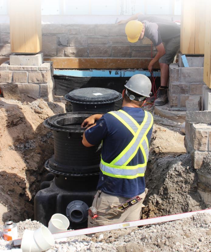
2 About Us Product Overview Extended Capacity Hydromechanical Grease Traps Endura XL 75 Models DGT75 598L Light Trafficable Lid DGT75P 598L Pedestrian Lid Industry leading separation efficiency based on testing to national standards. Comparable operational grease capacity 253kg to 2839ltr Gravity GT (concrete)* Operation is based on dynamic inlet baffle (Pat. Pend.) with internal flow control device. *based on 25% rule Moulding a Better Future Endura is manufactured by Canplas, one of North America s leading producers of plastic products for the building and construction industries specialising in injection moulded products. With five decades of expertise and experience in the manufacturing and distribution of plastic plumbing products, they process multiple materials and produce millions of fittings and products on an annual basis. Endura Grease Management products have demonstrated effective, efficient and consistent performance with over a decade of field installation and operation. Endura products are multi-patented and built to withstand the toughest environments, providing the flexibility of in-floor, on-floor and semi-recessed applications. Endura Earth Friendly solutions for Grease Management As an Aliaxis company, we are committed to the continuous improvement of our environmental performance and to meeting or exceeding the requirements of all applicable environmental laws and regulations. Durability Fewer installations and replacements result in lower lifetime costs and less landfill waste. Injection moulded in engineered thermoplastics, Endura Grease Traps will not corrode, chip or peel even under the most severe applications. Durability provides consistent operation no compromise of effectiveness due to deterioration of parts. Green by Design Light weight but durable grease trap units enable smaller carbon footprints and low-emissions transport. Injection and rotationally moulded thermoplastic requires less energy to produce than metal grease traps. Endura traps are manufactured using up to 100% recompounded material. Endura XL 100 Models DGT L Light Trafficable Lid DGT100P 973L Pedestrian Lid Industry leading separation efficiency based on testing to national standards. Comparable operational grease capacity 480kg to 3790ltr Gravity GT (concrete)* Operation is based on dynamic inlet baffle (Pat. Pend.) with internal flow control device. *based on 25% rule Endura XL Riser Extensions DGTR mm Riser Extension DGTR mm Riser Extension Cut to length riser system for burial up to 1828mm Grease Traps Generic Types The grease management industry has developed significantly in the past decade with not only more advanced and improved products but also development of performance standards and harmonisation of common terms and references. Traditionally the term Grease Trap is commonly applied and is still used in the industry today. This term is however progressively disappearing from technical references as the industry recognises that the term trap would suggest the presence of a water seal, integrally located within the interceptor. Modern traps are designed to be installed in conjunction with external water seal traps as a standard part of the system. Generically the application of a Grease Trap regardless of type is defined as follows: Grease Trap: A plumbing appurtence or appliance that is installed in a sanitary drainage system to intercept non-petroleum Fats, Oils and Grease (FOG) from a waste water discharge. Specific characteristics then define the three types of Interceptor Hydromechanical Grease Trap is sized by flow rate (L/Sec) and qualified separation/retention efficiency, validated against national performance standards. An HGT incorporates a defined means of flow control, acts to entrain air to effluent, includes interior baffling, or barriers in combination or separately, working to promote hydromechanical separation. Gravity Grease Trap are characterised by volume, minimum 30min retention time, baffles, not less than two compartments, a total volume of not less than 500 litres and gravity separation. Grease Removal Device are a hydromechanical grease trap that mechanically removes non-petroleum fats, oil and grease (FOG s) from the separation chamber, the control of which is either automatic or manually initiated and involves maintaining a liquefied state of intercepted FOG by heating.
 Seamless Tank rotationally moulded using up to 100% recompounded material Load Rated Access Covers")
 Mechanically secured Airtight/watertight cover, frame and adjustable riser system")


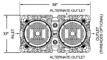
3 1092mm 889mm Model Chart Product Description Access Covers On Floor DGT75 DGT75P Grease Capacity 253kg >98% Efficiency Dynamic Inlet Baffle Internal flow control (supplied standard) Seamless Tank rotationally moulded using up to 100% recompounded material Load Rated Access Covers Light trafficable access cover Load rating 4,536kg Proof load test rating 9,072kg Class B rating (AS3996) Pedestrian access cover Load rating 907kg Proof load test rating 1,814kg Class A rating (AS3996) Mechanically secured Airtight/watertight cover, frame and adjustable riser system Limited warranty Light Point Trafficable Load Access 4,536kg Cover Point Load - 4,536kg Pedestrian Access Cover Point Load - 907kg DGT100 DGT100P Grease Capacity 480kg >98% Efficiency Dynamic Inlet Baffle Internal flow control (supplied standard) Seamless Tank rotationally moulded using up to 100% recompounded material Load Rated Access Covers Light trafficable access cover Load rating 4,536kg Proof load test rating 9,072kg Class B rating (AS3996) Pedestrian access cover Load rating 907kg Proof load test rating 1,814kg Class A rating (AS3996) Mechanically secured Airtight/watertight cover, frame and adjustable riser system Limited warranty Light Trafficable Access Cover Point Load - 4,536kg Pedestrian Access Cover Point Load - 907kg Dimensions XL75 Models 660mm 813mm INLET 559mm 355mm 1498mm 736mm 1003mm FRONT VIEW 813mm SIDE VIEW OUTLET TOP VIEW


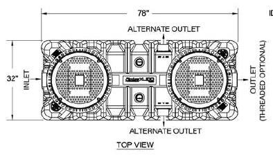
4 1029mm 1232mm Model Chart In-Floor Extension Riser Thermal Capability 12.7mm 150mm DGTR mm Riser DGTR mm Riser Full accessories & instructions supplied Robust, airtight, watertight 100% re-compounded riser Integral guidelines for cutting Prolonged intermittent discharge at 71 C 12.7mm 150mm DGTR mm Riser DGTR mm Riser Full accessories & instructions supplied Robust, airtight, watertight 100% re-compounded riser Integral guidelines for cutting Prolonged intermittent discharge at 71 C Dimensions XL100 Models 813mm 660mm 559 mm 355mm 1981mm 876mm 1232mm FRONT VIEW 813mm SIDE VIEW OUTLET TOP VIEW
5 Key Design Considerations Sizing by Flow Rate It is recommended that grease traps such as the Endura Traps are sized by flow rate. The use of flow control with a Hydromechanical Grease Trap is considered mandatory. Without a properly sized flow control, the discharge rate through into the trap may exceed the design rating of the unit, causing lower efficiencies and increased risk of grease, passing into the downstream system. Be careful not to confuse liquid capacity and flow rate. Liquid capacity is stated in litres while flow rate is reference in Litres per Minute, (LPM) or litres per second (L/S). Fixture Capacity: Most commonly used and recommended method for Hydromechanical Grease Traps. This method looks at the maximum capacity of fixtures connected to the trap and the time taken to discharge that volume of waste water through the trap. Units are expressed in Litres per Minute. (LPM) Calculation takes 75% of maximum capacity of all fixtures and based on a 1 or 2 minute period of time taken to discharge, results in a litres per minute flow rate. This number is rounded up to the next available size of trap. Table Table A Procedure A Procedure for Sizing for Grease sizing Grease Interceptors Traps STEP FORMULA EXAMPLE 1 Determine cubic content of fixture by multiplying length x width x depth 2 Determine Capacity in Litres 1 litre = 1000 cm³ 3 Determine actual drainage load The fixture is normally filled to approx. 75% of capacity with water as the items being washed displace about 25% of the total content. Actual drainage load = 75% of fixture capacity 4 Determine flow rate and drainage period In general, good practice dictates a one minute drainage period; however where conditions permit, a two minute drainage period is acceptable. Drainage period is defined as the actual time required to completely drain the fixture. Flow rate = Actual Drainage Load Drainage Period 5 Select Interceptor From Table B select the trap with a flow rating at least equal to the calculated flow rate. When calculated flow rate falls between two sizes, select the larger of the two interceptors A sink 600 mm long by 500mm wide by 300mm deep Cubic content: 600 x 500 x 300 = 90,000,000mm³ Contents in litres: 90,000,000/1000 = 90 litres Actual Drainage load: 0.75 x 90 = 67.5 litres Calculate flow rate for one minute drainage period: 67.5/1 min. = 67.5 L/min Calculate flow rate for two minute drainage period: 67.5/2 min. = L/min For a one minute drainage period: 67.5 L/min flow rate suitable for Endura XL75 For a two minute drainage period: L/min flow rate suitable for Endura XL75 Table B Grease Trap Trap Rating Rating Grease Trap Flow Rate L/Sec Flow Rate L/Min Endura XL L/sec L/min Endura XL L/sec 378 L/min
 253kg 480kg Average Efficiency % (ASME A112.14.")
6 Technical Data Capacities Endura XL75 Endura XL100 Part Numbers DGT75 DGT75P DGT100 DGT100P Litres per Second Min. Grease Capacity 68.2kg 90.8kg Grease Capacity Actual (ASME A ) 253kg 480kg Average Efficiency % (ASME A ) >98% >98% Operating Temperature Capabilities 71 C 71 C Access Cover - Load Rating Access Cover Proof Load Test Rating Class A 907kg Class B 4,536kg Class A 1,814kg Class B 9,072kg Class A 907kg Class B 4,536kg Class A 1,814kg Class B 9,072kg Unit Weight (Empty) 106kg 128kg Liquid Capacity 598 litres 973 litres Connection Size (Mechanical joint only) 100mm 100mm Internal Flow Control The flow control is an essential part of the hydromechanical grease trap and its function


7 External Flow Control (Optional) With the internal flow control plate removed, the flow control function will now be performed by a separate device that will be installed upstream from the trap. This is located as close as possible to the appliances and fixtures being served, but after the last branch connection to the main drain line connected to the trap. The flow control shall be installed so as to remain accessible for maintenance and will typically be recessed into the floor. The location of the cleanout should be recorded in your Installer Hand Over Checklist. Max. 7,620mm When installed with an External Flow Control, the internal flow control plate and seal shown are removed during installation. With the internal flow control in particular, it is important that it be opened and checked periodically (min. twice annually) to ensure there is no build up or blockage occurring that will restrict the flow. Tank Connections All Endura Grease Traps are supplied with standard no hub connections to accept locally approved/accepted MJ (Mechanical Joint) couplings. The Dux Flexible Coupling D is recommended. This method allows resilience in the connections to prevent stress and a flexible means of integrating metallic or plastic plumbing systems. Should adaption of pipe connection be required, use appropriate mechanical joint reducers but do not allow decrease pipe diameter across the unit. Note: Solvent cement is not an acceptable jointing method from the piping system to the trap. This will result in leakage. Dux Flexible Couplings are a mechanical joint and do not require solvent cement.
8 Air-Balanced Operation A hydromechanical grease trap is designed to operate as an air-balanced environment. This is vital to the function of the trap and as such no modification or removal of any parts should be made before, during or after installation unless specifically addressed in the respective Installation & Operation document. Venting Unlike Gravity Grease traps, a Hydromechanical Grease trap tank is not required to be directly vented. This would be detrimental to the function of the trap. All connected appliances shall be individually trapped and vented in accordance with local code requirements. The downstream drain carrying effluent to the municipal waste system shall also be vented to atmosphere in compliance with applicable local codes. Drain Cleanouts For installations below grade, most codes require the installation of a two way cleanout immediately before and after the respective inlet and outlet connections. These cleanouts will be extended to grade so as to remain accessible once the trap is operational. Head Effect An installation above or below grade that sees a fall equal to or in excess of 2.4m, when measured from the outlet of the highest appliance to the invert of the trap SHALL require the installation of a secondary flow control device to neutralise the effect of head pressure. The first flow control will be located as close as possible to the last appliance discharging to the trap, the second being located externally immediately before the trap or by utilising the manufacturers internal flow control device where available. Accessibility for Maintenance All grease traps regardless of generic type, require regular maintenance. Any design and subsequent installation shall make due consideration to the provision of access for the same as defined in the respective installation documentation. Installation documents are supplied with every trap. Copies are also available on the Dux website


9 Remote Pump XL Models Remote Pump (Optional): Endura XL incorporates a method for installation of a Remote Pump function where desirable or required. The simplicity of this change is such that it can be conducted in the field with minimum materials. The installation is based on the use of an 80mm DWV pipe which is passed into the tank by means of a tank penetration shown in Fig. B. 1. Cut the end of the pipe at an angle that is no less than 45 degrees. 2. Good preparation of this pipe end is essential to avoid damaging any seals used to seal the pipe. The outer edges must be chamfered to at least 45 around the full length of the pipe end. 3. Now measure from the end of the pipe to the following length depending if you are installing an XL75 or XL100 respectively. For an XL75 pipe length - 910mm; for XL100 pipe length 1,110mm Fig. A 4. On the top surface of the tank at the centre position and on either side of the air balance channel there are two Remote Pump Ready details, both of which include a drill centre (Fig. B). Select which of the two locations best suits your application and using a correctly sized hole saw, open the respective hole. 5. Fit penetration tank seal into the opening prepared and lubricate well using silicone pipe lubricant. 6. As the orientation of the pipe when installed is important, mark or identify on the top of the pipe so as to indicate that the angled face of the pipe will be facing laterally across the trap when installed. i.e. the angled face is pointed toward the opposite tank wall. 7. Take your prepared length of pipe and liberally apply silicone lubricant to at least the first 150mm of the pipe ensuring that the angled surface is also well lubricated. 8. Introduce the pipe to the rubber seal and with even pressure and a rotating motion, push the pipe through the seal and into the tank. Once onto the full diameter of the pipe apply more lubricant to the next mm and continue to push the pipe downward into the tank until the tip bottoms out, with the angled face in the correct position. 9. Develop your pump out line connecting to the pipe stub now extending from the tank using long sweep bends and fittings, making provision for adequate cleanout access as required. All joints must be solvent welded or of threaded format. Maximum developed pipe run shall be no greater than 7,620mm with a vertical rise of 2,438mm max. 10. At the extent of the remote pump system where the pumping service will be connected, typically a capped male camlock fitting will be provided to allow compatibility with vacuum service connection. Max. 2,438mm XL100 1,110mm XL75 910mm Max. 7,620mm
 required for PDI Installations Cleanout (recommended) Sink Vented Waste Air Intake CAUTION When backfilling")

10 In Floor Extended Capacity Do Not Exceed 7.6m XL Grease Trap Internal Flow Control and Baffle External Flow Control (optional) required for PDI Installations Cleanout (recommended) Sink Vented Waste Air Intake CAUTION When backfilling in-floor, the trap must have both the covers fitted and be filled with water to the inlet/outlet level. This will ensure the tank itself will not move during backfilling, pouring and/or floor finishing. When backfilling in particular, care should be taken to do so evenly around the unit and with light manual pressure only. Ensure that the trap is clearly defined to flooring contractors to prevent it from being covered with flooring material. Taping cardboard to the covers is generally effective. CAUTION CAUTION Caution: Clearance Required Locate the trap so as to allow for accessibility when conducting maintenance and regular cleaning. Set the trap on a firm, level surface ensuring the tank is equally supported. Risers Available where deeper installation is necessary to accommodate drainage. 450mm and 880mm Cut to Length riser pairs, Max extension 1.8m DGTR mm Riser DGTR mm Riser Full accessories & instructions supplied Robust, airtight, watertight 100% re-compounded riser Integral guidelines for cutting
 grade 60 steel per ASTM A615: connected with tie wire. Rebar to be 64mm from edge of concrete.")
 2 Way cleanout tee Side View Detail For Unit details see specification sheet for selected unit Risers to grade 2 Way cleanout tee Standard D156-44 Dux")

11 Interior or Exterior Below Grade Installations Extended Capacity Concrete Slab Detail For Traffic Loading Concrete to be 28 day compressive strength to 4,000 PSI. Reinforcement with N. 4 rebar (1.89mm) grade 60 steel per ASTM A615: connected with tie wire. Rebar to be 64mm from edge of concrete. Rebar spacing 300mm x 100mm spacing around access openings. Concrete Pad must extend min. 460mm outside the unit footprint No. 4 rebar (1.89mm) 2 Way cleanout tee Side View Detail For Unit details see specification sheet for selected unit Risers to grade 2 Way cleanout tee Standard D Dux Flexible Coupling Clean out to grade on outlet pipe of each unit Concrete slab Excavation and Backfill Detail Concrete slab Native Soil 150mm Min. base crushed aggregate material Approx. 20mm size rock, pea gravel or sand Crushed aggregate material approx. 20mm size rock, pea gravel or sand 1.828mm Max. Burial depth M Rated cover shown flush to grade (Light vehicle/pedestrian traffic only)
 per unit External flow controls installed upstream or internal flow control in each trap 2 x XL75 Parallel up to 568 L/Min, 507kg Grease")
12 Multi-Unit Parallel Installations Extended Capacity Parallel Installation: Parallel configurations shown are considered optimal for application and should be followed Intended for installations with high flow rate (greater than 60% of rated flow capacity) per unit External flow controls installed upstream or internal flow control in each trap 2 x XL75 Parallel up to 568 L/Min, 507kg Grease Capacity 2 x XL100 Parallel up to 757 L/Min, 960kg Grease Capacity 3 x XL100 Parallel up to 1,136 L/Min, 1,440kg Grease Capacity 4 x XL100 Parallel up to 1,514 L/Min, 1,920kg Grease Capacity
 External flow control upstream/installed only on first trap.")
13 Multi-Unit Series Installations Extended Capacity Series Installation: Series configurations shown are considered optimal for application and should be followed Intended for installations with low to medium flow (less than 60% of rated flow capacity) External flow control upstream/installed only on first trap. All other flow controls removed at installation 2 x XL75 Series up to 284 L/Min, 507kg Grease Capacity 2 x XL100 Series up to 378 L/Min, 960kg Grease Capacity 3 x XL100 Series up to 378 L/Min, 1,440kg Grease Capacity 4 x XL100 Series up to 1,514 L/Min, 1,920kg Grease Capacity 4 x XL100 Series up to 1,514 L/Min, 1,920kg Grease Capacity


14 BROGI General Information Endura Grease Traps are manufactured in an ISO 9001 and registered facility. Our quality management system has been registered for the design, manufacture and distribution of high quality injection molded products used in plumbing, industrial, ventilation and central vacuum applications Dux Industries Limited - Distributor 33 Mahia Road, Manurewa Auckland 2102 New Zealand
15 Notes
OPERATION, INSTALLATION AND MAINTENANCE INSTRUCTIONS SERIES INTERCEPTORS
 OPERATION, INSTALLATION AND MAINTENANCE INSTRUCTIONS 5400-5500 SERIES INTERCEPTORS 5401 75 4NH 5500 50 3IPS INSTALLATION Place the Wade interceptor downstream of the drain which will supply the oil laden
PLEASE DO NOT DISCARD THE ATTACHED DOCUMENT IS NECESSARY FOR THE INSTALLATION OF YOUR GREASE TRAP.
 PLEASE DO NOT DISCARD THE ATTACHED DOCUMENT IS NECESSARY FOR THE INSTALLATION OF YOUR GREASE TRAP. GI SERIES GREASE TRAP INSTALLATION GUIDE Overview Atlantic Metalworks GI series grease traps are designed
CHAPTER 10 TRAPS AND INTERCEPTORS TABLE 10-1 HORIZONTAL LENGTHS OF TRAP ARMS (EXCEPT FOR WATER CLOSETS AND SIMILAR FIXTURES) 1, 2
 1, 2") CHAPTER 10 TRAPS AND INTERCEPTORS < 1001.0 Traps Required. Each plumbing fixture, excepting those having integral traps or as permitted in Section 1001.1, shall be separately trapped by an approved type
CHAPTER 10 TRAPS AND INTERCEPTORS < 1001.0 Traps Required. Each plumbing fixture, excepting those having integral traps or as permitted in Section 1001.1, shall be separately trapped by an approved type
Innovative, Compact Design
 Innovative, Compact Design Easy, Effective Compliance What in the world is? The Thermaco, Inc. Trapzilla Supercapacity Grease Trap collects free-floating (non-emulsifed) grease & oils contained in kitchen
There are a few factors critical in the operation of a grease interceptor, which are: Design, Sizing, Proper installation and maintenance.
 TEL: 773-341-3030 FAX: 773-341-3046 TOLL FREE: 1-800-465-2736 WEBSITE: www.mifab.com Grease Interceptors Description of Operation: There are a few factors critical in the operation of a grease interceptor,
Engineering Fact Sheet
 GREASE INTERCEPTORS Service Alert Sensors Cast Iron Access Hatchway General Information Sewers back up an estimated 400,000 times each year in the United States causing approximately 40,000 municipal sanitary
1 Exam Prep Plumber s Handbook Tabs and Highlights
 1 Exam Prep Plumber s Handbook Tabs and Highlights These 1 Exam Prep Tabs are based on the Plumber s Handbook Revised 2006. Each Tabs sheet has five rows of tabs. Start with the first tab at the first
AIR ADMITTANCE VALVES FOR DOMESTIC PROPERTIES Guidance Notes
 AIR ADMITTANCE VALVES FOR DOMESTIC PROPERTIES Guidance Notes 02 AIR ADMITTANCE VALVES FOR DOMESTIC PROPERTIES Introduction For any system which drains waste water from a property to function correctly,
Combined FOG intercept and treatment system
 BIOLOGICAL DRAIN MAINTENANCE SYSTEM Combined FOG intercept and treatment system designed to retain and breakdown Fats, Oils and Grease (FOG) to prevent them from entering the drainage system. The system
CHaPTeR 10. TRaPS and INTeRCePTORS. Table 10-1 Horizontal lengths of Trap arms (except for water closets and similar fixtures)*
*") CHaPTeR 10 TRaPS and INTeRCePTORS 1001.0 Traps Required. 1001.1 Each plumbing fixture, excepting those having integral traps or as permitted in Section 1001.2, shall be separately trapped by an approved
CHaPTeR 10 TRaPS and INTeRCePTORS 1001.0 Traps Required. 1001.1 Each plumbing fixture, excepting those having integral traps or as permitted in Section 1001.2, shall be separately trapped by an approved
MASTERSPEC TECHNICAL SPECIFICATIONS DIVISION 22 PLUMBING. A. This Section includes the following sanitary drainage piping specialties:
 SECTION 221319 - SANITARY WASTE PIPING SPECIALTIES PART 1 - GENERAL 1.1 SUMMARY A. This Section includes the following sanitary drainage piping specialties: 1. Backwater valves. 2. Cleanouts. 3. Floor
2006 Thermaco, Inc. All rights reserved Patented/Patents Pending Specifications subject to change without notice
 One to Three Compartment Sink When planning a multiple fixture discharge into a single Big Dipper, establish the size unit required by following the method outlined in the sizing section of this manual.
Read Only Document Not For Distribution
 Chapter 5 Traps, Cleanouts and Backwater Valves 5.1 SEPARATE TRAPS FOR EACH FIXTURE a. Plumbing fixtures shall be separately trapped by a water seal trap placed as close as possible to the fixture outlet.
APPENDIX J ILLUSTRATIONS
 The following figures have been included in the 1994 edition of the Standard Plumbing Code to aid in interpreting this code. The figures are not to be construed as superseding the written text, but merely
How To Size A Big Dipper Unit
 Sizing Big Dipper Systems In Food Service Operations How To Size A Big Dipper Unit The purpose of this sizing procedure is to give a specifying engineer a simple method for determining the proper size
I. Best Management Practices (BMPs) to Prevent Blockages in the Sanitary Sewer System
 to Prevent Blockages in the Sanitary Sewer System") BMP Train kitchen staff and other employees about how they can help ensure BMPs are implemented. Post "No Grease" signs above sinks and on the front of dishwashers. I. Best Management Practices (BMPs)
BMP Train kitchen staff and other employees about how they can help ensure BMPs are implemented. Post "No Grease" signs above sinks and on the front of dishwashers. I. Best Management Practices (BMPs)
ECOJET GREASE LEVEL SENSOR
 ACO Passavant Installation guide ECOJET GREASE LEVEL SENSOR AUTHOR Kate Jennings DATE COMPLETED 8 August 2016 DATE COMPLETED V13 ACO Polycrete, 134-140 Old Bathurst Road, Emu Plains, NSW 2750 Tel: +61
CHAPTER 10 TRAPS AND INTERCEPTORS The vent pipe opening from a soil or waste No more than one (1) approved slip joint
 approved slip joint") CHAPTER 10 TRAPS AND INTERCEPTORS 1001.0 Traps Required. 1001.1 Each plumbing fixture, excepting those having integral traps or as permitted in Section 1001.2, shall be separately trapped by an approved
CHAPTER 10 TRAPS AND INTERCEPTORS 1001.0 Traps Required. 1001.1 Each plumbing fixture, excepting those having integral traps or as permitted in Section 1001.2, shall be separately trapped by an approved
CHAPTER 10 TRAPS AND INTERCEPTORS
 CHAPTER 10 TRAPS AND INTERCEPTORS 1001.0 Traps Required. 1001.1 Each plumbing fixture, excepting those having integral traps or as permitted in Section 1001.2, shall be separately trapped by an approved
ICP Plumbing Exam. Name: Carefully read each question and then circle the letter of the best answer.
 ICP Plumbing Exam Name: Date: Score: Carefully read each question and then circle the letter of the best answer. 1. A 1 inch diameter faucet, where the inside edge of the spout opening is 2.5 inches away
APPENDIX L ALTERNATE PLUMBING SYSTEMS
 ALTERNATE PLUMBING SYSTEMS L 1.0 General. L 1.1 Applicability. The intent of this appendix is to provide clarification of procedures for the design and approval of engineered plumbing systems, alternate
4. TECHNOLOGY AND DESIGN CRITERIA
 4. TECHNOLOGY AND DESIGN CRITERIA 12 Current FOG pretreatment technology typically takes the form of smaller, metal, grease-handling devices found in the kitchen area of the facility; or large, in-ground,
plumbing for greywater
 plumbing for greywater october 2015 christina bertea ~union trained journeywoman plumber (1978) ~plumbing contractor (1996) ~greywater action singingwater@jps.net plumbing for greywater basic parts of
STERI-VAC CENTRAL SUCTION SYSTEM
 STERI-VAC CENTRAL SUCTION SYSTEM INSTALLATION MANUAL This is a general installation manual for Steri-Vac Central Suction Systems. For detailed information see specific technical sheet. These are high-volume
TECHNICAL DATA. Wet 26a. February 22, 2009
 February 22, 2009 Wet 26a 1. DESCRIPTION The Viking Alarm Check Valve serves as a check valve by trapping pressurized water above the clapper and preventing reverse flow from sprinkler piping. The valve
Electrical cable Water supply tube Fittings for tube Coupler Teflon tape. Hole saw min. 2½" bit
 Installation Parts and Tools Parts not Provided Electrical cable Water supply tube Fittings for tube Coupler Teflon tape Air gap Wire nuts for 6-gauge wiring Hose clamp ⅞" UL approved strain relief Electrical
Summary of BBS Proposed Ohio Plumbing Code Rule Changes October 2016
 Summary of BBS Proposed Ohio Plumbing Code Rule Changes October 2016 Ohio Administrative Code Rule Number OPC Section IPC origin Reason for proposed 4101:3-2-01 Alternate on-site 2015 Added definition
CHAPTER 10 TRAPS AND INTERCEPTORS
 CAPTER 10 TRAPS AND INTERCEPTORS 1001.0 Traps Required. 1001.1 Each plumbing fixture, excepting those having integral traps or as permitted in Section 1001.2, shall be separately trapped by an approved
READ ONLY. Adopting Agency BSC SFM. Adopt Entire Chapter X X X Adopt Entire Chapter as amended (amended sections listed below) X X X X X X X
 X X X X X X X") CALIFORNIA PLUMBING CODE MATRIX ADOPTION TABLE CHAPTER 10 - TRAPS AND INTERCEPTORS (Matrix Adoption Tables are non-regulatory, intended only as an aid to the user. See Chapter 1 for state agency authority
CALIFORNIA PLUMBING CODE MATRIX ADOPTION TABLE CHAPTER 10 - TRAPS AND INTERCEPTORS (Matrix Adoption Tables are non-regulatory, intended only as an aid to the user. See Chapter 1 for state agency authority
INSTALLATION INSTRUCTIONS (CANADA)
") INSTALLATION INSTRUCTIONS (CANADA) MODEL GOS40 (OTHER MODELS ARE SIMILAR) INDEX: UNPACKING INSTRUCTIONS page 2 INSTALLATION INSTRUCTIONS page 3 Regular Installation Design but not limited to page 6 CONNECTIONS
INSTALLATION INSTRUCTIONS (CANADA) MODEL GOS40 (OTHER MODELS ARE SIMILAR) INDEX: UNPACKING INSTRUCTIONS page 2 INSTALLATION INSTRUCTIONS page 3 Regular Installation Design but not limited to page 6 CONNECTIONS
Installation Manual PS-225 & PS-275
 Installation Manual PS-225 & PS-275 Table of Contents Pre-Uncrating Checklist... 1 Verifying System Requirements... 2 Verifying System Direction... 2 Verifying the Electrical Requirements... 2 Removal
Building Utilities 1 Plumbing and Sanitary Systems
 Building Utilities 1 Plumbing and Sanitary Systems Taken from UST Architecture exams by Arch. Rafael Alli Recommended review material for UST Preboard Exam Prepared by: arkireviewph.multiply.com Types
MATERIALS Traps TRAPS. No. IPC IRC Description
 MATERIALS Traps TRAPS MAX " MAX 0" No. IPC IRC Description 00. P0.6 00. P0.6 00. P0. 00. () P0.6 Exc. Vertical distance from fixture to the trap weir can not exceed ". Horizontal distance from the fixture
Clean Water Made Easy. CWS Time Clock Softener Installation & Start Up Guide. Questions?
 Clean Water Made Easy www.cleanwaterstore.com CWS Time Clock Softener Installation & Start Up Guide Thank you for purchasing a Clean Water System! With proper installation and a little routine maintenance
Drain and Vent Systems 6 CE Hours
 Drain and Vent Systems 6 CE Hours Wisconsin Contractors Institute N27 W23953 Paul Road, Suite 203 Pewaukee, WI 53072 www.wicontractorsinstitute.com 262-409-4282 What is the purpose of this course? The
Installation Manual PS-200 & PS-201
 Installation Manual PS-200 & PS-201 Table of Contents Pre-Uncrating Checklist... 1 Verifying System Requirements... 2 Verifying System Direction... 2 Verifying the Electrical Requirements... 2 Removal
Modular Grease Trap MGTA
 Modular Grease Trap MGTA and MGTA) Installation Requirements Installation Water Requirements Corporation Water Corporation 22 Ethel Ave Brookvale NSW 2100 Postal: PO Box 255 Collaroy NSW 2097 Freecall
C. ASSE 1013: Performance Requirements for Reduced Pressure Principle Backflow Preventers.
 SECTION 22 10 00 PLUMBING PIPING AND PUMPS PART 1 - GENERAL 1.1 Purpose: A. This standard is intended to provide useful information to the Professional Service Provider (PSP) to establish a basis of design.
B. HI Compliance: Design, manufacture, and install pumps in accordance with HI "Hydraulic Institute Standards."
 PART 1: GENERAL 1.01 Purpose: A. This standard is intended to provide useful information to the Professional Service Provider (PSP) to establish a basis of design. The responsibility of the engineer is
IPC Plumbing Exam. Name: Carefully read each question and then circle the letter of the best answer.
 IPC Plumbing Exam Name: Date: Score: Carefully read each question and then circle the letter of the best answer. 1. A vent stack handling 25 dfu s with a developed length of 35 feet shall be inches minimum
TOWN OF SPENCER FIRE and EMERGENCY SERVICES
 TOWN OF SPENCER FIRE and EMERGENCY SERVICES Fire Prevention and Protection Regulations For Sub divisions 1. General requirements 2. Hydrants 3. Fire Cisterns Chapter 4. Dry Hydrants 5. Residential Sprinklers
Fleck 5600 Carbon Filter Installation & Start Up Guide
 Clean Water Made Easy www.cleanwaterstore.com Fleck 5600 Carbon Filter Installation & Start Up Guide Thank you for purchasing a Clean Water System! With proper installation and a little routine maintenance
SERVING CANADA INSTALLATION INSTRUCTIONS REVISED: AUGUST 2014
 SERVING CANADA INSTALLATION INSTRUCTIONS REVISED: AUGUST 2014 INDEX: UNPACKING INSTRUCTIONS page 2 INSTALLATION INSTRUCTIONS page 3 CONNECTIONS page 6 Equipment must be installed in compliance with all
SECTION PLUMBING
 SECTION 22 10 00 PLUMBING PART 1 GENERAL 1.1 WORK INCLUDED A. Furnish all labor, material and equipment necessary for the complete installation of the sanitary sewer system (including soil and vent piping),
A. Air Handling Units shall be designed to the specific requirements of the application: Recirculation or 100% Makeup.
 SECTION 23 70 00- CENTRAL HVAC EQUIPMENT PART 1: GENERAL 1.1 PURPOSE: A. This standard is intended to provide useful information to the Professional Service Provider (PSP) to establish a basis of design.
EUTECTIC EC-10DV Series
 EUTECTIC EC-10DV Series DIRECT VENT OIL-FIRED WATER BOILER/NO. 2 OIL VENTING INSTALLATION INSTRUCTIONS CONTENTS..........................................PAGE Basic Guidelines..........................................1
IH091: Home Wastewater Disposal System Installation Instructions & Warranty Information
 IH091: Home Wastewater Disposal System Installation Instructions & Warranty Information The Environment One grinder pump is a well-engineered, reliable and proven product. Proper installation ensures years
REVERSING DRUM MIXER
 REVERSING DRUM MIXER the leader in mixer design a new spin on mixers it is only sand, rock, water and cement until you mix it Without proper mixing, concrete will fail to achieve its desired properties.
ISO9001:2008 Cert Certified FIRE HYDRANTS. since SFFECO
 ISO9001:2008 Cert. 403 Certified FIRE HYDRANTS SFFECO since www.sffeco.com DRY BARREL FIRE HYDRANT Meets all applicable parts of ANSI/AWWA C502 standard UL Listed (EX16453) and FM Approved (FM1510) 250
STACKS AND STACK VENTS
 CHAPTER 9 VENTS SECTION 901 GENERAL 901.1 Scope. The provisions of this chapter shall govern the materials, design, construction and installation of vent systems. 901.2 Trap seal protection. The plumbing
MDX² INSTALLATION MANUAL
 ANTI-ENTRAPMENT DEBRIS DRAIN MDX² INSTALLATION MANUAL CONCRETE POOLS SUBMERGED SUCTION OUTLET FOR MULTIPLE DRAIN USE FOR USE ON FLOOR SEE SPECIAL INSTRUCTIONS FOR CALIFORNIA AND FLORIDA ON PAGES 4 AND
IRRIGATION EQUIPMENT LTD. The Perfect Solution for Water Filtration and Irrigation Problems
 IRRIGATION EQUIPMENT LTD. The Perfect Solution for Water Filtration and Irrigation Problems ODIS Filtration is The Heart of Every Irrigation System 12 TABLE OF CONTENTS Manifolds & Accessories... 2 Series
Level I Chapter 1 Worksheet
 Chapter 1 Worksheet 1. For applicability requirements of the Plumbing Code, refer to: a. Building Code b. Administration and Enforcement Code c. Plumbing Code d. Residential Code 2. The provisions of the
BARRINGTON PRESSURE LITE VITREOUS CHINA SIPHON JET TOILET K-4327
 BARRINGTON PRESSURE LITE VITREOUS CHINA SIPHON JET TOILET K-4327 BEFORE YOU BEGIN INSTALLER HAZARD NOTIFICATION WARNING: Risk of injury or water damage. Contents of vessel under pressure can cause severe
Procedural guide to the self-monitoring of trade waste pre treatment devices
 Procedural guide to the self-monitoring of trade waste pre treatment devices Introduction Manual for self monitoring of trade waste apparatus The purpose of this manual is to advise and assist customers
STEAM AND CONDENSATE PIPING AND PUMPS DESIGN AND CONSTRUCTION STANDARD
 PART 1: GENERAL 1.01 Purpose: A. This standard is intended to provide useful information to the Professional Service Provider (PSP) to establish a basis of design. The responsibility of the engineer is
Issue 4 Oct Panamatic Top loading Maxi & Optima 3 Installation
 Issue 4 Oct 2005 Panamatic Top loading Maxi & Optima 3 Installation Please Do handle the unit with care, to avoid scuffs and scratches during installation. Do not over-tighten plumbing or any other mechanical
Design of Precast Concrete Grease Interceptors
 Design of Precast Concrete Grease Interceptors Claude Goguen, PE National Precast Concrete Association 2015 Onsite Wastewater Mega Conference Terminology Terminology Terminology Grease is the Word If you
CITY OF OZARK STANDARD DRAWING DETAILS FOR PUBLIC IMPROVEMENTS
 CITY OF OZARK STANDARD DRAWING DETAILS FOR PUBLIC IMPROVEMENTS 2010 EDITION CITY OF OZARK, MISSOURI REVISIONS TO THE 2009 EDITION The following revisions have been made to the 2009 edition of the city
1.1 This section applies to air handling units for HVAC Systems.
 AIR HANDLING UNITS GENERAL INFORMATION 1.1 This section applies to air handling units for HVAC Systems. DESIGN REQUIREMENTS 2.1 Design Criteria a. The decision to use modular central station air handling
Duraplus ABS for Secondary Loop Refrigeration Control Systems
 Duraplus ABS for Secondary Loop Refrigeration Control Systems SECONDARY LOOP REFRIGERATION CONTROL SYSTEMS High Pressure Pipe, Valve & Fittings Environmentally Friendly Cooling Systems Low Temperature
REVIVAL LITE VITREOUS CHINA REVERSE TRAP TOILET
 REVIVAL LITE VITREOUS CHINA REVERSE TRAP TOILET BEFORE YOU BEGIN HOW TO USE THESE INSTRUCTIONS Please read these instructions carefully to familiarize yourself with the required tools, materials, and installation
A. ASME Compliance: Fabricate and install hydronic piping in accordance with ASME B31.9 "Building Services Piping.
 PART 1: GENERAL 1.01 Purpose: A. This standard is intended to provide useful information to the Professional Service Provider (PSP) to establish a basis of design. The responsibility of the engineer is
INSTALLATION INSTRUCTIONS REVISED: JUNE 2014
 INSTALLATION INSTRUCTIONS REVISED: JUNE 2014 INDEX: UNPACKING INSTRUCTIONS page 2 INSTALLATION INSTRUCTIONS page 3 CONNECTIONS page 6 Equipment must be installed in compliance with all applicable local
CHAPTER 9 VENTS. run undiminished in size and as directly as possible from the building drain through to the open air above the roof.
 CHAPTER 9 VENTS SECTION 90 GENERAL run undiminished in size and as directly as possible from the building drain through to the open air above the roof. 90. Scope. The provisions of this chapter shall govern
Keeping. Fats, Oils, and. Grease. Out of the Sewer
 Keeping Fats, Oils, and Grease Out of the Sewer Questions and Answers for Food Service Establishments regarding Fats, Oil, and Grease and Grease Removal Devices City of Paso Robles, Wastewater Division,
2016 Plumbing Supplemental Plan Review List
 Building Division 555 Santa Clara Street Vallejo CA 94590 707.648.4374 2016 Plumbing Supplemental Plan Review List POTABLE WATER SYSTEM P1. Specify which fixtures are for private use and which are for
SAN RAPHAEL PRESSURE LITE VITREOUS CHINA SIPHON JET TOILET
 SAN RAPHAEL PRESSURE LITE VITREOUS CHINA SIPHON JET TOILET BEFORE YOU BEGIN HOW TO USE THESE INSTRUCTIONS Please read these instructions carefully to familiarize yourself with the required tools, materials,
W-150-IS Specifications
 W-150-IS Specifications MOTOR/TIMER ENCLOSURE 14 CLEARANCE FROM TOP OF TANK REQUIRED FOR STRAINER BASKET & LID REMOVAL 10.25 2 PIPE / EMPTY INTO COOKING OIL RECYCLING CONTAINER DAILY GC-7 GREASE 8 QUART
DC Heat Recovery Unit MVHR Wholehouse heat recovery unit
 DC Heat Recovery Unit MVHR Wholehouse heat recovery unit Stock Ref. N DC Heat Recovery Unit MVHR 443423 Installation, Maintenance & Users Instructions PLEASE READ INSTRUCTIONS IN CONJUNCTION WITH ILLUSTRATIONS.
WELLWORTH /HIGHLINE WITH PEACEKEEPER VITREOUS CHINA TOILET
 WELLWORTH /HIGHLINE WITH PEACEKEEPER VITREOUS CHINA TOILET BEFORE YOU BEGIN HOW TO USE THESE INSTRUCTIONS Please read these instructions carefully to familiarize yourself with the required tools, materials,
Who Needs BIG DIPPER?
 Who Needs BIG DIPPER? Here s how An affordable Big Dipper system solves tough free-floating drainwater problems by removing and recovering up to 98.6% of the grease, oils, fats 1 2 and incidental food
D. NEMA Compliance: Provide electric motors and components which comply with NEMA standards.
 PART 1: GENERAL 1.01 Purpose: A. This standard is intended to provide useful information to the Professional Service Provider (PSP) to establish a basis of design. The responsibility of the engineer is
Direct Vent Training & Installation Instructions for Venting 40/50 gallon models Telescoping Vent Kit (standard)
") Choosing Location of the water heater This water heater is of the direct vent design. It takes all of its fresh air for combustion from outside the building which it is installed. It also vents the combustion
Choosing Location of the water heater This water heater is of the direct vent design. It takes all of its fresh air for combustion from outside the building which it is installed. It also vents the combustion
W-750-IS Specifications
 Big Dipper IS Central Automatic W-750-IS Specifications MOTOR/TIMER ENCLOSURE 1 CLEARANCE FROM TOP OF TANK REQUIRED FOR STRAINER BASKET & LID REMOVAL 23.375 EMPTY INTO COOKING OIL RECYCLING CONTAINER DAILY
CHAPTER 9 VENTS SECTION
 CHAPTER 9 VENTS SECTION 901 GENERAL 901.1 Scope. The provisions of this chapter shall govern the materials, design, construction and installation of vent systems. 901.2 Trap seal protection. The plumbing
SECTION BASIC MATERIALS AND METHODS
 SECTION 15050 BASIC MATERIALS AND METHODS PART 1 1.1 SECTION INCLUDES A. General Conditions B. Supplementary Conditions C. Division 1 D. Mechanical basic requirements E. Electric Motors F. Pipe, Valve,
Section 6 SPEL Stormceptor by-pass separators
 SPE Products data manual Section 6 SPE Stormceptor by-pass separators The SPE Stormceptor is the first Environment gency listed class 1 by-pass separator to S EN 858-1:2002. The Stormceptor provides a
ROLLAIR AIR COMPRESSORS
 AIR COMPRESSORS 40-50 - 60-75 QUALITY FOR COMPLETE SATISFACTION Our ambition at Worthington Creyssensac is to offer compressed air solutions that ensure maximum satisfaction to our customers. To reach
SUBCRITICAL & TRANSCRITICAL SYSTEMS
 R744 CO2 SYSTEMS SUBCRITICAL & TRANSCRITICAL SYSTEMS ORIGINAL MANUFACTURED EQUIPMENT R744 CO2 Systems BA-508-3 AUS In 2004 BITZER Australia introduced the Enviro-Cold CO 2 System to the Australian Refrigeration
I N D U S T R I A L Y A R D S
 I N D U S T R I A L Y A R D S GEOTEXTILES INDUSTRIAL YARDS 1.0 Features of INDUSTRIAL PG 2 YARDS 2.0 How Typar geotextiles PG 2 work 4.0 Installation guide PG 7 5.0 Overlap and joining PG 8 6.0 Setting
Dansereau Dental. P r e - C o n s t r u c t i o n G u i d e
 P r e - C o n s t r u c t i o n G u i d e 2 0 1 4 A m e r i c a s D e n t a l E q u i p m e n t C o m p a n y Dansereau Dental (800) 423-5657 / WWW.DHPDENTAL.COM M a n u fa c t u r e d i n U S A f o r
House Drainage System. Building Utility & Services
 House Drainage System Building Utility & Services Syllabus House Drainage: principles of house drainage, pipes and traps, Classification of traps: nahni trap, interception trap, grease-trap, sanitary fittings,
STOP RESIN TUB WITH INTEGRAL DRAIN PLANNING BEFORE YOU BEGIN TOOLS AND MATERIALS: GETTING STARTED INSTALLATION INSTRUCTIONS.
 BEFORE YOU BEGIN We recommend consulting a professional if you are unfamiliar with installing bathroom fixtures and plumbing. Signature Hardware accepts no liability for any damage to the floor, walls,
WATER HAMMER ARRESTORS & MISC. SPECIALTIES
 TABLE OF CONTENTS Pictorial Index Water Hammer Arrestors Certification Sizing & Placement Backwater Valves Typical Installations Trap Seal Primers Compliance Pressure & Flow Characteristics Typical Installations
FUEL OIL DAY TANKS. SST Level Controller: UL 508 LISTED
 FUEL OIL DAY TANKS SST Series - Engineering Submittal SST Series - Advanced Line Day Tanks Construction: UL 142 aboveground steel tank all seam welded, square, atmospheric tank of heavy gauge steel with
Geomembranes that work
 Geomembranes that work www.firestonebpe.com Dependable performance in demanding environments Firestone EPDM Geomembrane is a rubber liner offering a flexible and durable solution for a wide variety of
CRAFTSMAN EXAMINATION, JUNE 2007 PLUMBING ANSWER SCHEDULE
 No. 9195 CRAFTSMAN EXAMINATION, JUNE 2007 PLUMBING ANSWER SCHEDULE Plumbers, Gasfitters and Drainlayers Board, 2007. All rights reserved. No part of this publication may be reproduced by any means without
Series 57 WATER/OIL SEPARATORS
 Series 304 WATER AND OIL IN COMPRESSED AIR SYSTEM WATER ACCUMULATION When compressing air, a compressor draws in many other substances including water vapor. The compression process causes this water vapor
DURA RIMP. Goodall Duracrimp coupling system: INFERNO ISO A and SUPER INFERNO. A safe crimping connection for our GOODALL steamhoses
 Goodall Duracrimp coupling system: A safe crimping connection for our GOODALL steamhoses INFERNO ISO 6134-2A and SUPER INFERNO QUALITY SOLUTIONS DURA RIMP Content 1. Goodall DuraCrimp : A total solution
Tree Pits Construction Guide
 Tree Pits Construction Guide What are tree pits? Tree pits collect stormwater runoff from small carpark areas or roads. Runoff filters through the tree roots and surrounding soil mix, trapping sediment
Orange Township Fire Department Fire Prevention Bureau
 Orange Township Fire Department Fire Prevention Bureau Under Ground Fire Protection Plan Submittal Checklist Project Name: Project Address: Date: Designers Name: Company Name: Phone Number: Email: Fax:
TABLE OF CONTENTS. CHAPTER 2 DEFINITIONS General Applicability Definition of Terms General...
 TABLE OF CONTENTS CHAPTER 1 ADMINISTRATION................1 101.0 Title, Scope, and General...........1 101.1 Title............................1 101.2 Purpose.........................1 101.3 Plans Required...................1
DIVISION 21 - FIRE SUPPRESSION
 DIVISION 21 - FIRE SUPPRESSION DESIGN CRITERIA It is the policy of UC Davis to install fire sprinkler systems in all new construction/facilities. If the building is classified as a pole barn, shed, carport,
Fleck 2510 Sediment Filter Installation & Start-Up Guide
 Clean Water Made Easy www.cleanwaterstore.com Fleck 2510 Sediment Filter Installation & Start-Up Guide Thank you for purchasing a Clean Water System! With proper installation and a little routine maintenance
Grease Interceptors and Oil Separators
 Grease Interceptors and Oil Separators 1) All food service establishments and vehicle maintenance facilities shall have devices installed for separating and retaining grease and oils known as grease interceptors
CHAPTER 8 APPURTENANCES
 CHAPTER 8 APPURTENANCES 8.1 Introduction This chapter discusses several types of equipment used in onsite wastewater treatmenl 'disposal systems-that have 'general application to the components prev ously
D-11 OUTLINE SPECIFICATION FOR HTHW (ABOVE GRADE) HYDRONIC PIPING
 HYDRONIC PIPING") D-11 OUTLINE SPECIFICATION FOR HTHW (ABOVE GRADE) HYDRONIC PIPING PART 1 - GENERAL 1.1 RELATED DOCUMENTS A. Drawings and general provisions of the Contract, including General and Supplementary Conditions
D-11 OUTLINE SPECIFICATION FOR HTHW (ABOVE GRADE) HYDRONIC PIPING PART 1 - GENERAL 1.1 RELATED DOCUMENTS A. Drawings and general provisions of the Contract, including General and Supplementary Conditions
CRAFTSMAN EXAMINATION, NOVEMBER 2009 PLUMBING QUESTION AND ANSWER BOOKLET. Time allowed THREE hours
 Affix label with Candidate Code Number here. If no label, enter candidate Number if known No. 9195 CRAFTSMAN EXAMINATION, NOVEMBER 2009 PLUMBING INSTRUCTIONS QUESTION AND ANSWER BOOKLET Time allowed THREE
STOP ACRYLIC TUB WITH INTEGRAL DRAIN PLANNING BEFORE YOU BEGIN TOOLS AND MATERIALS: GETTING STARTED INSTALLATION INSTRUCTIONS.
 BEFORE YOU BEGIN We recommend consulting a professional if you are unfamiliar with installing bathroom fixtures and plumbing. Signature Hardware accepts no liability for any damage to the floor, walls,