East Brunswick Public Schools, NJ
|
|
|
- Peter Derek Sparks
- 5 years ago
- Views:
Transcription

1 , NJ Prepared For: Bernardo Giuliana, SFO School Business Administrator Financial Services Department 760 Route 18 Suite 109 East Brunswick, NJ Prepared By: Joe Coscia Energy Account Executive Honeywell Building Solutions 115 Tabor Road Morris Plains, NJ June 6, 2018
2 This Page Intentionally Left Blank
3 HONEYWELL PROPRIETARY Non-Disclosure Statement This proposal or qualification data includes data that shall not be disclosed outside the (the District) and shall not be duplicated, used or disclosed in whole or part for any purposed other than to evaluate this proposal or quotation. If, however, a contract is awarded to this Offeror as a result of -- or in connection with -- the submission of this data, the shall have the right to duplicate, use, or disclose the data to the extent provided in the resulting contract. This restriction does not limit the East Brunswick Public School s right to use information contained in this data if it is obtained from another source without restriction. The data subject to this restriction are contained in all sheets. Budgetary Proposal This budgetary proposal is provided for information and planning purposes only, to be used for feasibility decisions, planning, and budget development only, and is non-binding and does not constitute an offer for sale. Honeywell will be pleased to provide a firm price proposal upon request which will include all technical and commercial considerations General Disclaimer about Pre-Contract Information HONEYWELL MAKES NO REPRESENTATION OR WARRANTY REGARDING ANY FINANCIAL PROJECTIONS, DATA OR INFORMATION PROVIDED, EXCEPT AS MAY BE EXPRESSLY SET FORTH IN A DEFINITIVE AGREEMENT. Municipal Advisor Disclaimer HONEYWELL BUILDING SOLUTIONS, A STRATEGIC BUSINESS UNIT OF HONEYWELL INTERNATIONAL INC. ( HONEYWELL ), IS NOT A MUNICIPAL ADVISOR AND CANNOT GIVE ADVICE WITH RESPECT TO MUNICIPAL SECURITIES OR MUNICIPAL FINANCIAL PRODUCTS TO YOU ABSENT YOUR BEING REPRESENTED BY, AND RELYING UPON THE ADVICE OF, AN INDEPENDENT REGISTERED MUNICIPAL ADVISOR. HONEYWELL IS NOT SUBJECT TO A FIDUCIARY DUTY WITH REGARD TO YOU OR THE PROVISION OF INFORMATION TO YOU. INFORMATION ABOUT MUNICIPAL SECURITIES AND/OR MUNICIPAL FINANCIAL PRODUCTS, IF ANY, IS PROVIDED FOR EDUCATIONAL PURPOSES ABOUT POSSIBLE FINANCING OPTIONS AND IS NOT THE PROVISION OF ADVICE OR A RECOMMENDATION TO PURSUE ANY PARTICULAR FINANCING OPTION. CONSULT WITH YOUR INDEPENDENT REGISTERED MUNICIPAL ADVISOR ABOUT THE FINANCING OPTION APPROPRIATE FOR YOUR SITUATION. To ensure compliance with requirements imposed by the IRS under Circular 230, we inform you that any U.S. federal tax advice contained in this communication (including any attachments), unless otherwise specifically stated, was not intended or written to be used, and cannot be used, for the purpose of (1) avoiding penalties under the Internal Revenue Code or (2) promoting, marketing or recommending to another party any matters addressed herein. The information contained herein is general in nature and based on authorities that are subject to change. Honeywell Building Solutions, a strategic business unit of Honeywell International Inc., recommends that you consult your tax adviser to understand its applicability to specific situations.
4 This Page Intentionally Left Blank
5 TABLE OF CONTENTS Section A Executive Summary... 1 Section B Preliminary Utility Analysis... 5 Section C Energy Conservation Measures (ECMs)... 7 Introduction... 7 Energy Conservation Measures... 7 Overview... 8 ECM 1A Interior & Exterior Lighting Upgrades LED Retrofit ECM 1B De-stratification Fans ECM 1C Vending Misers ECM 1D Lighting Controls / BMS Integration ECM 2A Boiler Replacements ECM 2B Domestic Hot Water System Replacements ECM 2C Rooftop Unit Replacements ECM 2D Premium Efficiency Motors and VFDs ECM 2E Boiler Control Systems ECM 2F Kitchen Hood Controls ECM 2G Walk-in Compressor Controllers ECM 2H Chiller Replacement ECM 2I Booster Heater Conversion ECM 2J Emergency Generator ECM 2K Replace Power Exhaust Fan with Energy Recovery Unit ECM 3 Building Management System (BMS) Upgrades A - BMS Enhancement to Niagara4 Platform/HVAC Shutdown B - BMS Integration of Non-Connected Components C - BMS Indoor Air Quality (IAQ) Monitoring ECM 3D Demand Control Ventilation ECM 4A Building Envelope Improvements ECM 4B Roof Replacements ECM 5A Computer Power Management ECM 6A Combined Heat and Power ECM 7A Permanent Load Reduction Program ECM 8A Solar Power Purchase Agreement (PPA) ECM 9A High Efficiency Transformers Section D Technical and Financial Summary Recommended ESIP Project Form II: Recommended Project - Energy Conservation Measures (ECMs) Summary Form Form III: Recommended Project - Projected Annual Energy Savings Data Form Form IV: Recommended Project - Projected Annual Energy Savings Data Form in MMBTUs Form V: Recommended Project ESCO s Proposal Project Cost Form Form VI: Recommended Project ESCO s Preliminary Annual Cash Flow Analysis Form Building by Building Simple Payback Summary (Hard Costs Only) Utility and Other Rebates and Incentives Financing the ESIP Debt Issuance Tax-Exempt Lease Purchase Financing Certificates of Participation (COP s) Energy Savings Obligations Section E Measurement & Verification and Maintenance Plan Baseline Adjustment to Baseline Methodology... 92
6 3. Energy Savings Calculations Measurement & Verification Site Specific M&V Plan Guarantee of Savings Recommended Preventive Maintenance Services Section F Design Approach Safety Management Plan Project Management Process A. Honeywell Performance Contracting B. Project Management Policy: Honeywell's Commitment to Health, Safety and the Environment C. Project Management Process Construction Management Commissioning Installation Standards Implementation Schedule Appendix 1 Independent Energy Audits Appendix 2 ECM Calculations Appendix 3 Cutsheets Appendix 4 Safety Management Plan
7 SECTION A EXECUTIVE SUMMARY Honeywell is pleased to submit this for the. During the development of the, Honeywell has completed a thorough investment grade energy audit of the East Brunswick Public School's buildings and grounds. Based on the audit findings and Honeywell s extensive experience in working with municipalities, we can confidently state that we can deliver a financially viable, comprehensive solution to address East Brunswick Public School's facility concerns. Our includes projects that achieve energy and operational efficiencies, create a more comfortable and productive working environment and are actionable via the New Jersey Energy Savings Improvement Program (NJ ESIP) in accordance with NJ PL2012, c.55. The is the core of the NJ ESIP process. It describes the energy conservation measures that are planned and the cost calculations that support how the plan will pay for itself through the resulting energy savings. Under the law, the must address the following elements: The results of the energy audit; A description of the energy conservation measures (ECMs) that will comprise the program; An estimate of greenhouse gas reductions resulting from those energy savings; Identification of all design and compliance issues and identification of who will provide these services; An assessment of risks involved in the successful implementation of the plan; Identify the eligibility for, and costs and revenues associated with, the PJM Independent System Operator for demand response and curtail-able service activities; Schedules showing calculations of all costs of implementing the proposed energy conservation measures and the projected energy savings; Maintenance requirements necessary to ensure continued energy savings, and describe how they will be provided; and If developed by an ESCO, a description of, and cost estimates of a proposed energy savings guarantee. The purpose of this document is to provide all the information required for the to determine the best path forward in the implementation of a District-Wide NJ ESIP Project. It is important to note that the provides a comprehensive evaluation of ALL potential ECMs within the. This is not meant to infer that all the ECMs identified can be implemented. However, if the ECM is part of this plan, it may be implemented later as additional funding becomes available or technology changes to provide for an improved financial return. Our is structured to clearly demonstrate compliance with the NJ ESIP law, while also presenting the information in an organized manner which allows for informed decisions to be made. The information is divided into the following sections: A. Executive Summary (This Section) B. Preliminary Utility Analysis The Preliminary Utility Analysis (PUA) defines the utility baseline for the East Brunswick Public School buildings included in the. It provides an overview of the current usage and a cost per square foot by building of utility expenses. The report also compares the East Brunswick Public School's utility consumption to that of other districts in the same region on a per square foot basis. C. Energy Conservation Measures This section includes a detailed description of the ECMs we have selected and identified for your School District. It is specific to your facilities in scope, savings methodology and environmental impact. It is intended to provide a basis of design for each measure in narrative form. It is not intended to be a detailed specification for construction. ALL potential ECMs for the are identified for the purposes of potential inclusion in the program. Final selected ECMs are to be determined by the in conjunction with Honeywell during the project development phase of the NJ ESIP process. D. Technical and Financial Summary This section includes an accounting of all technical and financial outcomes associated with the ECMs as presented on the New Jersey Board of Public Utilities Forms II through IV. Information detailed on the forms includes projected implementation hard costs, projected energy savings, projected operational savings and projected Page 1
8 environmental impact. Form VI: Annual Cash Flow Analysis provides a rolled-up view of the overall project financials, inclusive of financing costs, on an annual basis as well as over the entire 15 or 20-year term of the agreement. Based on our preliminary discussions with the, the following sample self-funding project has been provided for review and consideration: Recommended ESIP Project Value of Project $8,706,789 Term of Repayment 15 Years Projected Savings Over Term $13,072,750 Projected NJ Rebates & Incentives $1,097,368 Projected Interest Rate 3.5% E. Measurement & Verification and Maintenance Plan This section identifies the intended methods of verification and measurement for calculating energy savings. These methods are compliant with the International Measurement and Verification Protocols (IMVP), as well as other protocols previously approved by the Board of Public Utilities (BPU) in New Jersey. This section also includes the recommended maintenance requirements for each type of equipment. Consistent maintenance is essential to achieving the energy savings projected in this plan. F. Design Approach This section includes a summary of Honeywell s best practices for the successful implementation of a NJ ESIP project. It includes a project specific Safety Management Plan and provides an overview of our project management procedure, construction management and a sample schedule for the overall completion of the project. Within the schedule, we clearly define the tasks directed towards compliance with architectural, engineering and bidding procedures in accordance with New Jersey Public Contracts Law. G. Independent Energy Audit This section includes, for reference, the independent energy audits as previously received by the through the Local Government Energy Audit (LGEA) program. The audits, provided by CHA have been included on a USB drive as Appendix 1. A comparison can be made between the ECMs outlined in this Independent Energy Audit and the additional ECMs described in the overall. H. Energy Calculations and Greenhouse Gas Reduction Summary This section titled Appendix 2: ECM Calculations includes all the energy calculations required to ensure compliance with the law and to confirm the energy savings can, and will, be achieved. These calculations are subject to an independent 3 rd party engineering firm review for verification. A summary of all savings based on the Recommended ESIP Project includes a reduction in 3,990,901 kwh (kilowatt hours of electricity), 102,494 Th (Therms of Natural Gas) and 2641 Metric Tons of Greenhouse Gas (GHG) emissions. It is the equivalent of removing 557 cars from the road for an entire year and is the same as planting 2,501 acres of forest. I. Equipment Cut-sheets This section titled Appendix 3: Equipment Cut-sheets includes specification data for the equipment which shall be utilized as the basis of design for plans and specifications during the subsequent project development and NJ public bid phase. J. Safety Management Plan This section titled Appendix 4: Safety Management Plan establishes a plan for the implementation of Honeywell s Safe Operations Management (SOM) program. The document includes procedures and requirements specific to the necessary to support a safe workplace for all stake holders. The Safety Management Plan is a living document, which will be updated and modified to maintain its relevance throughout the project as site conditions and circumstances change. In accordance with the NJ ESIP process, the next step in the project development phase is for Honeywell to provide our recommendations and for the to select the desired content of the project based upon the East Brunswick Public School's unique goals and objectives. The selections will consider the projected costs, projected energy and operational savings, available financing options at the time of the agreement, interest rates, length of term and East Brunswick Public Schools priorities, which will all play a part in the final selection and cash flow of ECMs. The definitive requirement under NJ PL2012, c.55 is that the project is self-funding within the 15 or 20-year term as outlined in the legislation. Page 2

9 Overall, it is evident that the is well positioned to implement a program that will upgrade your facilities, while funding itself within the requirements of the law and with zero impact on your taxpayer base. We welcome this opportunity to partner with the to improve the comfort and efficiency of your facilities through the successful implementation of this. Sincerely, Joseph J. Coscia Energy Account Executive Page 3
10 This Page Intentionally Left Blank Page 4
11 SECTION B PRELIMINARY UTILITY ANALYSIS Page 5
12 This Page Intentionally Left Blank Page 6

13 Preliminary Utility Analysis East Brunswick BOE East Brunswick, NJ Helping customers manage energy resources to improve financial performance
14 Executive Summary Honeywell would like to thank you for the opportunity of providing you with this Preliminary Utility Analysis. A one year detailed billing analysis was completed for all utility data provided by your staff. The facility's electric and gas consumption were compared to a benchmark of typical facilities of similar use and location. It should be noted however, that some of Buildings which make up the benchmarking standards are not equipped with mechanical cooling (air conditioning). Therefore, these buildings may unjustly appear to be less efficient in comparison. Through our Energy Services offerings, Honeywell's goal is to form a long term partnership for the purpose of meeting your current infrastructure needs by focusing to: Improve Operational Cost Structures Ensure Satisfaction Upgrade Infrastructure While Reducing Costs Meet Strategic Initiatives Leverage Teamwork Pursue Mutual Interests Provide Financing Options How does it work? Under an energy retrofit solution, Honeywell installs new, energy efficient equipment and optimizes your facility, as part of a multi-year service contract. Most of these improvements are cost-justified by energy and operational savings. Some of the energy conservation measures provide for a quick payback, and as such, would help offset other capital intensive energy conservation measures such as, boilers, package rooftop units, domestic hot water heaters, etc. The objective is to provide you with reduced operating costs, increased equipment reliability, optimized equipment use, and improved occupant comfort. After review of the utility analysis, you can authorize Honeywell to proceed with the development of a detailed engineering report. The report development phase allows Honeywell to prepare an acceptable list of proposed energy conservation measures, which are specific to the selected facility. Some examples of typical Energy Conservation Measures include: Lighting Control Systems Boilers AC Units/Condensers Building Enevelope Package Rooftop Units Domestic Hot Water Heaters Plug Load Management Why Honeywell? Honeywell is one of the world leaders in providing infrastructure improvements With Honeywell as your building partner, you gain the advantage of more than 115 years of leadership in building services Honeywell has the infrastructure and manpower in place to manage and successfully implement your project Honeywell has over 30 years experience in the energy retrofit marketplace with over $5 Billion in customer energy savings Honeywell provides you with "Single Source Responsibility" - from Engineering to Implementation, Servicing and Financing (if desired)
 $0.12201 $0.901 Electric Demand (kw) 49,253 * Costs include energy and demand components, as well as taxes, surcharges, etc.")
15 Historical Summary Utility Analysis Period: September August 2017 Current Year (9/16-8/17) Electric Therms (Gas) Utility Costs* $1,963,615 $495,352 Utility Usage (kwh, Therms) 16,094, ,782 $ Cost/Unit (kwh, Therms) $ $0.901 Electric Demand (kw) 49,253 * Costs include energy and demand components, as well as taxes, surcharges, etc. Actual Cost by Utility - 9/16-8/17 $1,963,615 80% $495,352 20% Electric Natural Gas Total Cost = $2,458,967
.")
16 The calculation of EUI (Energy Use Intensity) is shown below. EUI, expressed in kbtu/sf, is normalized for floor area, the most dominant influence on energy use in most buildings. Its use usually provides a good approximation of how your building's energy performance compares to others. Site EUI indicates the rate at which energy is used at your building (the point of use). Source EUI indicates the rate at which energy is used at the generation sources serving your building (the point of source) and indicates the societal energy penalty due to your building The lower the EUI, the higher the rating, indicating that the building is more efficient than other buildings. The greater the EUI, the lower the rating, indicating that there is an opportunity for higher potential benefits from operational improvements. The Source EUI below has been applied to a Department of Energy statistical model from the Oak Ridge National Laboratory web site, The Department of Energy has estimated energy use and cost reductions for building source EUI ratings (percentiles) in the table below. Please see the DOE Regional Source EUI Comparison graph below to rate your building in relation to the regional distribution of similar type buildings. (Note: The Source EUI includes the inefficiencies of electrical generation and transmission. A reduction in 'electrical' source EUI includes a benefit in terms of reduction of air pollution emissions and green house gases, and is thus an indicator of societal benefit.) Energy Benchmarking Source EUI Rating for your Building Energy use and cost reduction potential (%) Walk-thru energy assessment recommended? above 60% below 25% No 40 to 60% 20 to 35% Maybe 20 to 40% 35 to 50% Yes Below 20% above 50% Definitely Site EUI Rank Annual Total Electrical Use (kwh) Annual Total Non-Electrical Fuel Use (Therms) Building Gross Floor Area (sqft) Site EUI Rating Source EUI: Annual Total Source Energy Use per Sq-Ft (kbtu/sf) Rating (Regional Source EUI Comparison) 1 Bowne Munro Elementary School 339,040 15,895 32, Churchill Junior High School 2,221,820 49, , East Brunswick High School 2,767, , , Hammarskjold Middle School 2,817, , , Irwin Elementary School 368,520 18,960 43, Lawrence Brook Elementary School 708,355 29,740 77, Robert Frost Elementary School 342,840 18,595 52, Warnsdorfer Elementary School 324,750 30,529 55, Administration Building/BOE 585, , Central Elementary School 1,797,900 38,983 78, Chittick Elementary School 2,638,709 26,057 52, Memorial Elementary School 930,631 36,734 82, Support Operations Facility 250,922 20,840 32, School Facilities Source EUI Est Regional Rating Building % Bowne Munro Elementary School % Churchill Junior High School % East Brunswick High School % Hammarskjold Middle School % Irwin Elementary School % Lawrence Brook Elementary School % Robert Frost Elementary School % Warnsdorfer Elementary School % Administration Building/BOE % Central Elementary School % Chittick Elementary School % Memorial Elementary School 144 0% Support Operations Facility
17 Utility Analysis - Electric Square Footage Analysis $8.00 $7.00 Cost per Sq. Ft. $7.34 $6.00 $5.00 $4.00 $3.00 $2.82 $2.70 $2.00 $1.00 $1.46 $0.84 $0.87 $1.04 $1.29 $1.29 $0.93 $0.90 $1.65 $1.13 $0.00 Bowne Munro Elementary School Churchill Junior High School East Brunswick High School Hammarskjol d Middle School Irwin Elementary School Lawrence Brook Elementary Robert Frost Elementary School Warnsdorfer Elementary School Administratio n Building/BOE Central Elementary School Chittick Elementary School Memorial Elementary School Support Operations Facility Usage (kwh) per Sq. Ft kwh/sq ft Bowne Munro Elementary School Churchill Junior High School East Brunswick High School Hammarskjol d Middle School Irwin Elementary School Lawrence Brook Elementary School Robert Frost Elementary School Warnsdorfer Elementary School Administratio n Building/BOE Central Elementary School Chittick Elementary School Memorial Elementary School Support Operations Facility


18 Utility Analysis - Electric Sources of Electric Consumption 2% 3% 6% Typical End Use Allocation * 5% 3% 7% 45% 9% 20% Lighting Cooling Ventilation Office Equipment Refrigeration Cooking Heating Other Water Heating **This allocation is generic and is not a representation of the actual end use in your buildings included in this report. Typical Allocation Applied to Your Electric Cost** Lighting $883,627 Cooling $392,723 Ventilation $180,653 Office Equipment $137,453 Refrigeration $39,272 Cooking $58,908 Heating $117,817 Other $49,090 Water Heating $98,181 Your 7/09-6/10 Total Cost $1,963,615
19 Utility Analysis - Natural Gas $1.00 Square Footage Analysis Cost per Sq. Ft. $0.60 $0.50 $0.39 $0.38 $0.33 $0.41 $0.35 $0.35 $0.43 $0.45 $0.44 $0.38 $0.22 $0.00 Bowne Munro Churchill Junior East Brunswi Hammarsk jold Irwin Element Lawrence Brook Robert Frost Warnsdorf er $0.01 Administra tion Central Element Chittick Element Memorial Element Support Operatio 70.0 Usage (kbtu) per Sq. Ft Bowne Munro Elementary Churchill Junior High East Brunswick High School Hammarskjold Middle School Irwin Elementary Lawrence Brook Robert Frost Elementary Warnsdorfer Elementary 0.6 Administration Building/BOE Central Elementary Chittick Elementary Memorial Elementary Support Operations


20 Utility Analysis - Natural Gas There is a fairly direct correlation between your gas usage and heating degree days, indicating that the vast majority of your natural gas usage is for space heating. 10% 7 Sources of Natural Gas Usage Typical End Use Allocation * 2% 5% 83% Heating Water Heating Cooking Misc **This allocation is generic and is not a representation of the actual end use in your buildings included in this report. Typical Allocation Applied to Your Gas Cost** Heating $411,142 Water Heating $49,535 Cooking $9,907 Misc $24,768 Your 1/14-12/14 Total Cost $495,352

21 Annual Emissions & Environmental Impact East Brunswick BOE Calendar Year 9/2016-8/2017 The following energy usage, cost and pollution have been quantified: Total Annual Electric usage Annual Natural Gas usage 16,094,294 kwh 549,782 Therms Annual Greenhouse Gas Emissions CO2 SO2 NOx 28,091,971 pounds 74,195 pounds 50,697 pounds This is equivalent to one of the following: 300 No. of passenger vehicles - annual greenhouse gas emissions 176,715 Gallons of gasoline consumed - CO 2 emissions 3,653 Barrels of oil consumed - CO 2 emissions 134 No. of homes energy use for one year - CO 2 emissions 40,282 No. of tree seedlings grown for 10 years - carbon sequestered 335 No. of acres of pine or fir forests - carbon sequestered annually 65,458 No. of propane cylinders used for home barbeques - CO 2 emissions 8 No. of railcars' worth of coal burned - CO 2 emissions Based on the US Environmental Protection Agency - Clean Energy Power Profiler
22 Potential Retrofits Retrofit Description Utility/Fuel Type Symptomatic Issues Common Recommendations for Action Lighting Retrofit and Motion Sensors Electric/Natural Gas Elevated EUI Lighting and Controls UpGrade De-Stratification Fans Electric/Natural Gas Elevated EUI Redistribution of Conditioned Air DHW Boiler Replacements Electric/Natural Gas Elevated EUI Higher Efficiency Units RTU Replacements Electric/Natural Gas Elevated EUI Higher Efficiency Units Building Envelope Improvements Electric/Natural Gas Elevated EUI Reduce Building In leakage Computer Controllers Electric Elevated EUI Lower Energy Consumption Install Premium Efficient Motors Electric Elevated EUI Lower Energy Consumption Transformer Replacements Electric Elevated EUI Lower Energy Consumption Water Conservation Water/Sewer Elevated EUI Lower Water Consumption CHP Electric/Natural Gas Elevated EUI Lower Energy Consumption Solar PPA Electric Elevated EUI Lower Energy Supply Side Charges BMS Upgrades Electric/Natural Gas Elevated EUI Lower Energy Consumption Load Reduction Electric Elevated EUI Lower Energy Supply Side Consumption
23 SECTION C ENERGY CONSERVATION MEASURES (ECMS) INTRODUCTION The information used to develop this Section was obtained through the independent energy audit building surveys to collect equipment information, interviews with operators and end users, and an understanding of the components to the systems at the sites. The information obtained includes nameplate data, equipment age, condition, the system s design and actual load, operational practices and schedules, and operations and maintenance history. Honeywell has done a review of the Energy Conservation Measures (ECMs) which would provide energy and cost savings to the. This report aims to be an assessment of the feasibility and cost effectiveness of such measures, and an indication of the potential for their implementation. The ECMs listed below have been reviewed throughout your facilities for consideration within a complete. What follows is a general description of the energy auditing process and the detailed descriptions of the Energy Conservation Measures for your facilities. ENERGY CONSERVATION MEASURES ECM ECM Description Bowne Munro ES Churchill Junior HS East Brunswick HS Hammarskjold MS Irwin ES Lawrence Brook ES Robert Frost ES Warnsdorfer ES Admin Building Central ES Chittick ES Memorial ES Support Operations 1A LED Lighting 1B Destratification Fans 1C Vending Misers 1D Lighting Controls/BMS Integration 2A Boiler Replacement 2B DHW Boiler Replacement 2C RTU Replacements 2D Motor and VFD Replacements 2E Boiler Control Systems 2F Kitchen Hood Controls 2G Walk-in Compressor Controls 2H Chiller Replacements 2I Booster Heater Conversion 2J Standby Generator 2K Replace PEF with ERU 3A BMS Enhancement to Niagara 4 Platform/HVAC Shutdown 3B BMS Integration of Non- Connected Components 3C BMS Indoor Air Quality Monitoring 3D Demand Control Ventilation 4A Building Envelope Improvements 4B Roof Replacement 5A Computer Power Management 6A Cogeneration 7A Permanent Load Reduction 8A Solar PPA 9A Transformers Page 7
24 OVERVIEW Honeywell has closely evaluated and audited the to develop the optimum mix of energy saving measures. These selected site-specific measures have been developed using the following process: Review Site Audits Engineering Team Site Visits Develop Measures Review Measures with Team Reject and Accept Measures Based On Alignment with Critical Success Factors (CSF) Value to the District Economic Financial Payback Equipment Service Life Effect on Current Space Conditions In developing the proposed measures, the following considerations were critical: Reduction of space heating and cooling loads by performing a systems review, with complete consideration of current indoor environmental quality standards. Review and redesign lighting systems noting reductions in the internal heat gain in the affected spaces. Load reduction measures always precede optimization measures. Bin weather data was used from a 15-year average reported from Newark, NJ. Ventilation rates, taken from ASHRAE published standard, were predicted by using the building s population multiplied by cfm/person during occupied hours. Reasonable infiltration rates were assumed based on the building s fenestration conditions and expected values for typical school buildings. A reduced infiltration rate was assumed for the unoccupied hours. Envelope heat loss calculations assumed a reasonable heat transmission rate (U value) based on the construction of the buildings. Wall area and glass area were estimated by supplied drawings and field photographs. Current efficiencies were derived from assumed and later to be measured boiler efficiencies, and assumed system losses due to thermal losses, distribution losses and loose operational control. The current assumed boiler system efficiencies were then applied to the calculated load and calibrated to last year s actual fuel consumption. Demand Sensitive Operation Review existing and proposed thermal loads. For example, the review process will facilitate the application of: 1. Optimized flow rates (steam, water, and air). 2. Optimized operation of equipment, matching current occupancy use profiles and considering both outside and indoor space temperatures. Benefits of Mechanical Improvements Listed below are some of the benefits that the District would reap from the mechanical portion of the measures: 1. Avoid costly repairs and replace equipment that would have to be replaced in the next five years. 2. Improved compliance with ASHRAE Ventilation Standards. 3. Ability to trend ventilation rates; thus, insuring compliance through documentation. 4. Operating a more weather sensitive facility. 5. Allowing for a greater capability of central monitoring and troubleshooting via remote. 6. Greater operating flexibility to reduce costs and optimize staff efficiency. Indoor Air Quality Implementation of new energy-related standards and practices has contributed to a degradation of indoor air quality. In fact, the quality of indoor air has been found to exceed the Environmental Protection Agency (EPA) standards for outdoor air in many homes, businesses, and factories. Page 8
25 The American Council of Governmental Industrial Hygienists (ACGIH) in their booklet Threshold Limit Values, has published air quality standards for the industrial environment. No such standards currently exist for the residential, commercial, and institutional environments, although the ACGIH standards are typically and perhaps inappropriately used. The EPA has been working to develop residential and commercial standards for quite some time. Recent studies indicate that for even the healthiest students, indoor air pollution can reduce the ability to learn. As an example, if you were to place a number of students in a room where it s hot, there s little or no air circulation and other children are coughing and sneezing, exposing the student body to airborne related illnesses such as the cold or flu. Honeywell has addressed this issue by focusing on the proper operation and replacement of the unit ventilators and air handler equipment which will assure IAQ standards are met. Page 9
26 This Page Intentionally Left Blank Page 10


27 ECM 1A INTERIOR & EXTERIOR LIGHTING UPGRADES LED RETROFIT The key benefits of this ECM include: Energy Savings from reducing total energy consumption with more efficient, state of the art technology. Today s most efficient way of illumination and lighting has an estimated energy efficiency of 80%-90% when compared to traditional lighting and conventional light bulbs. Improved teacher and student performance from enhanced lighting quality that translates to an enhanced working and learning environment. Improved equipment longevity by reducing amount of light usage and extending the useful life of your lighting system. LED bulbs and diodes have an outstanding operational life time expectation of up to 100,000 hours. This is 11 years of continuous operation, or 22 years of 50% operation. Operational savings in terms of bulb and ballast replacement are significant based on this technology. Reduced maintenance and operational costs by modernizing your lighting system and providing for longer lasting and technologically advanced lights, without the need to address deficient or bad ballasts. ECM ECM Description Bowne Munro ES Churchill Junior HS East Brunswick HS Hammarskjold MS Irwin ES Lawrence Brook ES Robert Frost ES Warnsdorfer ES Admin Building Central ES Chittick ES Memorial ES Support Operations y 1A LED Lighting Existing Conditions Lighting throughout the buildings is comprised mostly of fluorescent tube lay-in fixtures with 32-watt T-8 and T-12 lamps and a mixture of mostly electric and few magnetic ballasts. In these buildings, the large spaces, such as the multi-purpose rooms and gymnasiums, are served by CFL high bay fixtures. Storage rooms, bathrooms and closets are lit with a mixture of fluorescent and compact fluorescent lamps. Existing gym lights at Bowne-Monroe Elementary School Existing classroom lighting at Irwin Elementary School Scope of Work We propose to replace fluorescent and HID lights with lower wattage LED lamps/fixtures. LED technology offers significant advantages such as extended lamp life, instant on and high energy conversion efficiency, and significant maintenance and operational savings. Page 11


28 We propose to first remove the existing ballasts and replace them with LED drivers (using approximately 24V) and eliminate the need for ballasts. We will then remove the existing lamps and replace them with the latest, state of the art, high efficiency LED lamps. Replacements or maintenance is not required for up to 100,000 hours or years depending on usage time. Here are several representative images of LED lighting we install on our projects: Hillsborough HS Music Room Flat Panel LEDs Hillsborough HS Gym LED Upgrades Changes in Infrastructure New LED lamps will be installed as part of this ECM. Existing poles and shoe box fixtures will be utilized. Customer Support and Coordination with Utilities Coordination efforts will be needed to reduce or limit impact to building occupants. Environmental Issues Resource Use Waste Production Energy savings will result from reduced electric energy usage. A slight increase in heating energy is resultant from the reduced heat output of more efficient interior lamps. All lamps and ballasts that are removed will be properly disposed. Environmental Regulations No environmental impact is expected. Page 12


29 ECM 1B DE-STRATIFICATION FANS The key benefits of this ECM include: Improved efficiency & energy savings through more equal distribution of conditioned air space Equipment longevity due to lower utilization of equipment to condition air Increased comfort of occupants to improve productivity of students and teachers ECM ECM Description Bowne Munro ES Churchill Junior HS East Brunswick HS Hammarskjold MS Irwin ES Lawrence Brook ES Robert Frost ES Warnsdorfer ES Admin Building Central ES Chittick ES Memorial ES Support Operations 1B Destratification Fans Existing Conditions Warm air stratifies close to the ceiling in high ceiling areas such as in a gymnasium or auditorium. Elevated levels of heat transfer through the high walls and roof causes elevated heat loss. Proposed Solution In areas with 20+ foot ceiling heights, there is approximately a 15 F+ temperature difference between the floor and the ceiling. With higher ceilings, it is even greater. That means to generate the heat necessary to maintain a comfortable 70 F temperature at the floor level, where student activities occur, the ceiling could be 85 F or higher. De-stratification fans de-stratify the air to a zero to 3 F differential from floor to ceiling and wall to wall. This will allow HVAC systems to run for a shorter duration because of the absence of extreme temperatures to heat or cool, thus allowing the local thermostats to be satisfied for longer periods of time. Systems Evaluation and Selection An energy-efficient motor drives a near-silent fan that forces a column of hotter air from the ceiling area to the cooler floor below. As this column of warm air nears the floor, it begins to flare out in a circular pattern and rise again creating a torus. While doing so, it warms the cooler air and mixes with air near the floor, increasing the temperature and comfort of occupants. Through a natural law of physics, this torus will continue to re-circulate air, mixing warmer air from the ceiling with cooler air near the floor until the ceiling and air temperatures are nearly equal. As this happens, it will require less and less energy to comfortably heat the work area, allowing thermostats to be lowered and energy savings to be realized. Once started, the entire process of thermal equalization will take on average less than 24 hours. Page 13
30 Based on a site investigation conducted by our staff, we propose to install the following as indicated in the table below: School Location Qty Type Bowne Munro Elementary School Multi-Purpose Room 4 Air Pear 25 Churchill Junior High School Main Gym 14 Air Pear 45 Churchill Junior High School Aux Gym 2 Air Pear 15 Churchill Junior High School Cafetorium 4 Air Pear 45 East Brunswick High School Main Gym 10 Air Pear 25 East Brunswick High School Sub Gym 4 Air Pear 25 East Brunswick High School Lower Gym 8 Air Pear 25 Hammarskjold Middle School Gym 1 6 Air Pear 45 Hammarskjold Middle School Gym 2 6 Air Pear 45 Irwin Elementary School Multi-Purpose Room 4 Air Pear 25 Lawrence Brook Elementary School Gym 4 Air Pear 25 Lawrence Brook Elementary School Cafetorium 4 Air Pear 25 Robert Frost Elementary School Multi-Purpose Room 4 Air Pear 15 Warnsdorfer Elementary School Gym 2 Air Pear 25 Central Elementary School Multi-Purpose Room 4 Air Pear 15 Central Elementary School Gym 4 Air Pear 45 Chittick Elementary School Multi-Purpose Room 4 Air Pear 25 Memorial Elementary School Gym 4 Air Pear 45 Memorial Elementary School Media Center 2 Air Pear 25 Memorial Elementary School Cafetorium 4 Air Pear 25 Total 98 Table 1B.1 Proposed De-Stratification Fans Scope of Work Per De-Stratification Fan: Shut off the main electric power to the area in which the unit(s) will be installed. Install new de-stratification fan and wiring. Re-energize. Inspect unit operation by performing electrical and harmonics testing. Changes in Infrastructure New de-stratification fans will be installed as part of this ECM. Customer Support and Coordination with Utilities Coordination efforts will be needed to reduce or limit impact to building occupants. Environmental Issues Resource Use Waste Production Energy savings will result from reduced thermal energy usage. A slight increase in electrical energy is resultant from the increase run time of the fan motors. None. Environmental Regulations No environmental impact is expected. Page 14


31 ECM 1C VENDING MISERS The key benefits of this ECM include: Energy Savings by better managing the power consumption of electrical equipment Longer equipment life thanks to reduced usage ECM ECM Description Bowne Munro ES Churchill Junior HS East Brunswick HS Hammarskjold MS Irwin ES Lawrence Brook ES Robert Frost ES Warnsdorfer ES Admin Building Central ES Chittick ES Memorial ES Support Operations 1C Vending Misers The has plug loads for equipment such as vending machines at multiple locations. As such, Honeywell has investigated the use of vending misers for these areas. Existing Conditions Vending machines are located throughout your facilities offering soft drinks to the occupants. A typical cold drink machine consumes over 5,000 kwh annually. Building Type Location Qty Bowne Munro Elementary School Cold Beverage Teacher Lounge 1 Churchill Junior High School Cold Beverage Cafetorium 1 Churchill Junior High School Cold Beverage Cafetorium 1 Churchill Junior High School Snack Cafetorium 1 Churchill Junior High School Cold Beverage Teachers' Lounge 1 Churchill Junior High School Snack Teachers' Lounge 1 East Brunswick High School Cold Beverage Cafetorium 1 East Brunswick High School Snack Cafetorium 1 East Brunswick High School Cold Beverage Gym 1 East Brunswick High School Snack Gym 1 East Brunswick High School Cold Beverage Gym 1 Hammarskjold Middle School Cold Beverage Cafetorium 1 Hammarskjold Middle School Snack Cafetorium 1 Hammarskjold Middle School Cold Beverage Cafetorium 1 Hammarskjold Middle School Snack Cafetorium 1 Page 15
32 Building Type Location Qty Hammarskjold Middle School Snack Teachers' Lounge 1 Hammarskjold Middle School Cold Beverage Teachers' Lounge 1 Hammarskjold Middle School Cold Beverage Teachers' Lounge 1 Irwin Elementary School Cold Beverage Teacher Lounge 1 Lawrence Brook Elementary School Cold Beverage Teacher Lounge 1 Lawrence Brook Elementary School Snack Teacher Lounge 1 Robert Frost Elementary School Cold Beverage Teacher Lounge 1 Warnsdorfer Elementary School Cold Beverage Teacher Lounge 1 Warnsdorfer Elementary School Snack Teacher Lounge 1 Administration Building Cold Beverage Kitchen 1 Administration Building Snack Kitchen 1 Central Elementary School Cold Beverage Teacher Lounge 1 Central Elementary School Snack Teacher Lounge 1 Chittick Elementary School Cold Beverage Teacher Lounge 1 Memorial Elementary School Cold Beverage Teacher Lounge 1 Memorial Elementary School Snack Teacher Lounge 1 Support Operations Cold Beverage Break Room 1 Support Operations Snack Break Room 1 Total 33 Table 1C.1 Existing Vending Machines Proposed Solution Utilizing a Passive Infrared (PIR) Sensor, the VMOC completely powers down a vending machine when the area surrounding it is unoccupied. Once powered down, the VMOC will monitor the room s temperature and use this information to automatically repower the vending machine at one to three hour intervals, independent of occupancy, to ensure proper vending product temperature control. The VMOC also monitors electrical current used by the vending machine. This ensures that the unit will never power down a vending machine while the compressor is running, so a high head pressure start never occurs. In addition, the current sensor ensures that every time the vending machine is powered up, the cooling cycle is run to completion before again powering down the vending machine. The Coca Cola Company and Pepsi Corporation approve the proposed controller for use on their machines. Interface with Existing Equipment All of the plug load control devices are easily installed. The vending machine controllers are installed separately from the machine, and implementation will occur during working hours. A period of three (3) weeks will be required to verify proper calibration of the sensors. With respect to the vending machines in your facilities, Honeywell has estimated the number and types of vending machines based on our site tour. During the implementation phase, Honeywell will check with the vendor about the type and specification of the vending machines as it relates to any internal time clocks which may exist inside the machine. Should this be the case, the savings and cost will be adjusted accordingly. Changes in Infrastructure New vending machine controls will be installed as part of this ECM. Customer Support and Coordination with Utilities Minor coordination efforts will be needed to reduce or limit impact to building occupants. Page 16
33 Environmental Issues Resource Use Energy savings will result from reduced electric energy usage. Waste Production Environmental Regulations None. No environmental impact is expected. Page 17
34 This Page Intentionally Left Blank Page 18


35 ECM 1D LIGHTING CONTROLS / BMS INTEGRATION The key benefits of this ECM include: Energy Savings from reducing total energy consumption with more efficient, state of the art technology. Today s most efficient way of illumination and lighting has an estimated energy efficiency of 80%-90% when compared to traditional lighting and conventional light bulbs. Improved equipment longevity by reducing amount of light usage and extending the useful life of your lighting system. Operational savings in terms of bulb and ballast replacement are significant based on this technology. Reduced maintenance and operational costs by modernizing your lighting system and providing for longer lasting and technologically advanced lights, without the need to address deficient or bad ballasts. ECM ECM Description Bowne Munro ES Churchill Junior HS East Brunswick HS Hammarskjold MS Irwin ES Lawrence Brook ES Robert Frost ES Warnsdorfer ES Admin Building Central ES Chittick ES Memorial ES Support Operations 1D Lighting Controls / BMS Integration Existing Conditions Educational institutions, such as K- 12 Districts, are focused on providing classrooms and campuses for their teachers and students that are safe, healthy, energy-efficient and provide the best environment for learning. And they are also chartered with reducing the costs of building operations. Current conditions do not allow for remote operation of the lighting systems within the buildings. Solution Honeywell proposes to install additional JACE Controllers to be integrated with the District Building Management and tied into the lighting circuits to provide BMS Control of the lighting systems and help the District achieve its goals. Examples of existing lighting Page 19

36 Example of JACE (Java Application Control Engine) Controllers Scope of Work Integrate of JACE Controller System to Inteface with BMS The system acts like the extension for the building and helps give you more control of your facilities. With this integration, the buildings are more efficient and comfortable and also may increase occupant productivity. An integrated Lighting Control system CanLower energy costs from lighting: LED lighting greatly lowers cost together with adjusting light levels by occupancy and settings Reduce Insurance Rates: Real-time tracking of students/staff or assets in buildings for safety and security; transparency of building Lower Maintenance Costs: Based on installing long-lasting LED lights, plan cleaning schedule based on use of area Analyze Space Utilization in Real Time: Identify occupied and unoccupied spaces for energy savings, safety and determine best usage of space Changes in Infrastructure New JACE controllers will be installed as part of this ECM. Customer Support and Coordination with Utilities Coordination efforts will be needed to reduce or limit impact to building occupants. Environmental Issues Resource Use Energy savings will result from reduced electric energy usage. Waste Production None. Environmental Regulations No environmental impact is expected. Page 20
37 ECM 2A BOILER REPLACEMENTS The key benefits of this ECM include: Reduced energy usage from improved boiler efficiency thanks to replacement of older equipment Lower operational costs through less frequent maintenance and operational issues ECM ECM Description Bowne Munro ES Churchill Junior HS East Brunswick HS Hammarskjold MS Irwin ES Lawrence Brook ES Robert Frost ES Warnsdorfer ES Admin Building Central ES Chittick ES Memorial ES Support Operations 2A Boiler Replacements Existing Conditions The boilers at East Brunswick High School are close to their useful life and are not as efficient as condensing boilers. The boilers at Central Elementary School are not as efficient as condensing boilers. East Brunswick High School Existing Boilers Central Elementary School Existing Boilers School Location Manufacturer Model Qty Input Fuel East Brunswick High School Boiler Room Bryan RW850-W-FDGO 3 6,800 MBH Gas Central Elementary School Boiler Room Weil McLain 1, ,612 MBH Gas Table 2A.1 Existing Boiler Equipment Proposed Solution It is recommended that the boilers listed in the above Table 2A.1 be replaced with boilers operating at higher efficiency listed in Table 2A. 2. New condensing hot water boilers have thermal efficiencies that range from 88% 95% depending on the return hot water temperature from the heating loop. With proper design, it is typical to see thermal efficiencies of around 92%. Thermal efficiency is only one part of the equation that makes up the seasonal efficiency of a boiler. Compared to the existing boilers in these schools, the new boilers will provide an increase in boiler efficiency of anywhere between 10% to 15%. Page 21
38 School Location Manufacturer Model Qty Input Fuel East Brunswick High School Boiler Room Aerco BMK ,000 MBH Gas Central Elementary School Boiler Room Aerco BMK ,500 MBH Gas Table 2A.2 Proposed Boiler Equipment Scope of Work The following outlines the boiler replacement: Disconnect gas back to shutoff valve and electric back to source panel-board. Remove existing boilers. Install new boilers. Connect gas and heating hot water appurtenances to new boilers. Terminate and power new boiler electric circuiting. Start up, commissioning and operator training. Energy Savings Methodology and Results In general, Honeywell uses the following approach to determine savings for this specific measure: Existing Boiler Efficiency Proposed Boiler Efficiency Energy Savings $ = Existing Heat Production/ Existing Fuel Input = Proposed Heat Production/ Proposed Fuel Input = Heating Production (Proposed Efficiency Existing Efficiency) Equipment Information Manufacturer and Type Equipment Identification Several quality and cost effective manufacturers are available. Honeywell and the customer will determine final selections. As part of the ECM design and approval process, specific product selection will be provided for your review and approval. Changes in Infrastructure New boiler will be installed in itemized locations; in addition, training for maintenance personnel will be required as well as ongoing, annual preventive maintenance. O&M Impact The new boilers will decrease the O&M cost significantly for maintaining the boilers. Customer Support and Coordination with Utilities Minor support will be required for the interruption of utilities for brief tie-in periods. Continuity of service must be maintained for the customer. Environmental Issues Resource Use Waste Production Environmental Regulations Energy savings will result from greater combustion efficiency, reduced maintenance costs control and setback. Existing boilers scheduled for removal will be disposed of properly. No environmental impact is expected; all regulations will be adhered to in accordance with EPA and local code requirements. Page 22


39 ECM 2B DOMESTIC HOT WATER SYSTEM REPLACEMENTS The key benefits of this ECM include: Reduced energy usage from improved efficiency thanks to replacement of older equipment Lower operational costs through less frequent maintenance and operational issues ECM ECM Description Bowne Munro ES Churchill Junior HS East Brunswick HS Hammarskjold MS Irwin ES Lawrence Brook ES Robert Frost ES Warnsdorfer ES Admin Building Central ES Chittick ES Memorial ES Support Operations 2B DHW Boiler Replacement Existing Conditions The existing domestic hot water heaters are generally in good condition but are not high-efficiency units. East Brunswick High School Existing DHW Heater Chittick Elementary School Existing DHW Heater Building Manufacturer Model Qty Capacity MBH Fuel Central Elementary School AO Smith BTH Gas Central Elementary School AO Smith BTH Gas Chittick Elementary School AO Smith BTR Gas Churchill Junior High School PVI 1060 N 250A PV Gas East Brunswick High School PVI 54P 250A-MX Gas Table 2B.1 Existing Equipment Proposed Solution Honeywell proposes replacing the existing DHW heaters at the above schools with highly efficient condensing DHW heaters. New condensing DHW heaters have efficiencies between 92% - 94%. They provide better control with capabilities as night setback, temperature adjustments and demand control hot water. Building Manufacturer Model Qty Capacity MBH Fuel Central Elementary School AO Smith BTX Gas Central Elementary School AO Smith BTX Gas Page 23
40 Building Manufacturer Model Qty Capacity MBH Fuel Chittick Elementary School AO Smith BTH Gas Churchill Junior High School Lochinvar AWN701PM Gas East Brunswick High School Lochinvar AWN400PM Gas Table 2B. 2 Proposed Equipment Scope of Work The following outlines the domestic hot water heater replacement: Disconnect and remove old water heaters Furnish and install condensing gas fired domestic hot water heaters as specified in the table above Install all required piping, controls, and breeching Install mixing valve Install circulators for building use Test and commission Energy Savings Methodology and Results The savings are calculated from the domestic hot water heater efficiency differences. Existing Equipment Efficiency Proposed Equipment Efficiency Energy Savings = Existing Boiler Efficiency + Existing Heat Exchanger Efficiency = Efficiency of the New Domestic Hot Water Heater = DHW Load x (Existing Equipment Efficiency New Equipment Efficiency) Changes in Infrastructure A new controller for each heater will be installed and programmed. In addition to the controllers, training for maintenance personnel will be required. Equipment Information Manufacturer and Type Equipment Identification Several quality and cost effective manufacturers are available. The following is an example of equipment that may be utilized. Honeywell and the Customer will determine final selections. As part of the measure design and approval process, specific product selection will be provided for your review and approval. Customer Support and Coordination with Utilities Minor support will be required for the interruption of utilities for brief tie-in periods. Environmental Issues Resource Use Energy savings will result from improved thermal efficiency. Waste Production This ECM will produce no waste by-products. Environmental Regulations No environmental impact is expected. Utility Interruptions Proper phasing procedures will minimize gas interruptions. Page 24


41 ECM 2C ROOFTOP UNIT REPLACEMENTS The key benefits of this ECM include: Improved efficiency & energy savings through replacement of old, end of useful life equipment Equipment longevity due to more efficient and less wasteful equipment utilization ECM ECM Description Bowne Munro ES Churchill Junior HS East Brunswick HS Hammarskjold MS Irwin ES Lawrence Brook ES Robert Frost ES Warnsdorfer ES Admin Building Central ES Chittick ES Memorial ES Support Operations 2C RTU Replacements Existing Conditions Some Rooftop Units (RTUs) serving the schools marked above are inefficient or past their useful lives. Replacing these units with new, high efficiency units will save energy costs over the long term while reducing repair costs that would otherwise have been necessary to keep the old RTUs in operation. School Make Model Location Served Qty. Tons Bowne Munro Elementary School Carrier 48HJF007-M-531NB Resource Room/Computer Lab Central Elementary School Carrier 48HJF006-M-521INB Music Room East Brunswick High School General Electric BTC048D300D0 Faculty Dining East Brunswick High School Trane TCD049C40CBD C-1/C-19/Dance Room East Brunswick High School Trane TCD061C40CBD E-10 Photography/G-5 and G East Brunswick High School Lennox LGA150SH21 Upper Media Center East Brunswick High School Lennox GCS24D Y Computer Lab (G4) East Brunswick High School Trane TCD121C40CAA E East Brunswick High School Trane TCD121C40CAA E East Brunswick High School Trane TCD061C40CBD G-5/G East Brunswick High School Lennox GCS Y Lower Media Center East Brunswick High School Trane TCD061C40CBD G East Brunswick High School Trane TCD061C40CBD G East Brunswick High School Trane TCP024F100AA G-10 Co-Op Office East Brunswick High School Trane TCD086C40CBC C East Brunswick High School Lennox GCS24D Y Conference Room Media Center Page 25
42 School Make Model Location Served Qty. Tons Lawrence Brook Elementary Music/Computer Lab/Media Carrier 48HJF005-M-531NB School Center/Faculty Administration Building Carrier 50HJQ Offices Table 2C. 1 Existing Rooftop Units to be Replaced Proposed Solution Honeywell proposes replacing the existing rooftop units in the above table. The new units will be installed in the same location as the existing units. Existing electrical power supply will be reconnected to the new units. The units will communicate with the building management system. School Make Model Location Served Qty. Tons Bowne Munro Elementary School Lennox LGH072H4B Resource Room/Computer Lab Central Elementary School Lennox LGH060H4E Music Room East Brunswick High School Lennox LCH048U4E Faculty Dining East Brunswick High School Lennox LCH048U4E C-1/C-19/Dance Room East Brunswick High School Lennox LCH060H4E E-10 Photography/G-5 and G East Brunswick High School Lennox LGH150H4B Upper Media Center East Brunswick High School Lennox KGB024S4D Computer Lab (G4) East Brunswick High School Lennox LCH122U4E E East Brunswick High School Lennox LCH122U4E E East Brunswick High School Lennox LCH060H4E G-5/G East Brunswick High School Lennox KGB024S4D Lower Media Center East Brunswick High School Lennox LCH060H4E G East Brunswick High School Lennox LCH060H4E G East Brunswick High School Lennox KGB024S4D G-10 Co-Op Office East Brunswick High School Lennox LGH092H4B C East Brunswick High School Lennox KGB024S4D Conference Room Media Center Lawrence Brook Elementary School Lennox LCH048U4E Music/Computer Lab/Media Center/Faculty Administration Building Lennox LCH060H4E Offices Table 2C. 2 Proposed Rooftop Units Scope of Work The following outlines the scope of work to install the condensing units stated in the above table: Disconnect existing RTU electric connections. Disconnect piping and air ducts from the unit. Remove unit from the base. Modify base for new unit if necessary. Run new gas line for gas fired units. Rigging and setting new unit at the base. Inspect piping and air ducts before reconnecting them to the unit. Reconnect piping and air ducts. Repair duct and piping insulation. Connect electric power. Start up and commissioning of new unit. Maintenance operator(s) training. Energy Savings Methodology and Results The savings approach is based on the energy efficiency between the existing and new units. The savings are generally calculated as: Page 26
43 Electric Energy savings Existing unit energy consumption (kwh) replacement unit energy consumption (kwh) Equipment Information Manufacturer and Type Equipment Identification Several quality and cost effective manufacturers are available. Honeywell and the District will determine final selections. Product cut sheets and specifications are available upon request. As part of the measure, design and approval process, specific product selection will be provided for your review and approval. Customer Support and Coordination with Utilities Coordination of the electrical tie-in will be required. Environmental Issues Resource Use Energy savings will result from higher efficiency units. Waste Production Existing rooftop unit scheduled for removal will be disposed of properly. Environmental Regulations No environmental impact is expected. Page 27
44 This Page Intentionally Left Blank Page 28


45 ECM 2D PREMIUM EFFICIENCY MOTORS AND VFDS The key benefits of this ECM include: Energy Savings from reduced run hours and reduced motor speeds Equipment longevity due to more efficient and less wasteful equipment utilization and reduced startup wear ECM ECM Description Bowne Munro ES Churchill Junior HS East Brunswick HS Hammarskjold MS Irwin ES Lawrence Brook ES Robert Frost ES Warnsdorfer ES Admin Building Central ES Chittick ES Memorial ES Support Operations 2D Motor and VFD Replacements ECM Overview Variable frequency drives (VFDs) allow motors to run at specified speeds rather than just on or off while allowing systems to more accurately move heat. Honeywell recommends this ECM due to the significant savings potential given the relationship between energy consumption and motor speed. Existing Conditions Honeywell has identified standard efficiency electric motors on several pumps. Energy savings can be obtained by replacing the standard efficiency motors with premium efficiency motors as well as by installing Variable Frequency Drives on systems that have two-way control valves. The motors that were identified in the buildings are listed as follows: Building Equipment Description Qty Motor HP Replace Add VFD Motor Y/N Y/N Bowne Munro Elementary School HHW Y Y Chittick Elementary School HHW Y Y Churchill Junior High School HHW Y Y Robert Frost Elementary School HHW Y Y Table 2D. 1 Existing Motors and Replacements Page 29
46 Proposed Solution Honeywell identified a number of the buildings have pump systems, hydronic systems and the motors that serve them that are sized to meet peak heating or cooling conditions. However, we ve learned that most operating hours occur during conditions that require less than peak loads. Honeywell proposes replacing of all above-mentioned single speed standard efficiency motors (that do not have VFDs) with new premium efficiency motors, installing new couplings where applicable. In addition, Honeywell recommends installing VFDs on these pumps. Energy used by the motor can be reduced by varying the flow in response to varying loads in the space. Motor speed may be controlled either based on the pressure in the distribution system or based on time of day. Honeywell recommends replacing applicable three-way valves with two-way valves to ensure proper system operation and control. Honeywell also recommends installing VFDs on the heating hot water pumps and chilled water pumps to better match pumping output to system requirements and reduce energy waste. Each motor will be equipped with new selector relays that will allow one drive to operate per pump with the VFD drive. Honeywell also recommends installation of new differential pressure sensors and tying them to the control system to allow you to regulate the speed of the pump according to load requirements. Lastly, we recommend installation of VFDs on the cooling system pump motors that have higher horsepower. VFDs will maintain temperatures in the unit by adjusting the speed of both the motor and the pump, and can be connected to your BMS. Energy Savings Methodology and Results The energy consumed by electric motors varies inversely with the cube of the motor speed. Variable speed drives reduce motor speed (in response to load) thus reducing energy consumption exponentially. Equipment Information Manufacturer and Type Equipment Identification Several quality and cost effective manufacturers are available. The following is an example of equipment being utilized. Honeywell and the School District will determine final selections. Product cut sheets and specifications for generally used are available upon request. As part of the measure design and approval process, specific product selection will be provided for your review and approval. Changes in Infrastructure New motors will be installed in place of the old motors. No expansion of the facilities will be necessary. Customer Support and Coordination with Utilities Coordination of the electrical tie-in will also be required. Environmental Issues Resource Use Waste Production Environmental Regulations Energy savings will result from reducing electrical usage by operating higher efficiency motors for the same horsepower output. The equipment uses no other resources. This measure will produce waste byproducts. Old motors shall be disposed of in accordance with all federal, state and local codes. No environmental impact is expected. Page 30


47 ECM 2E BOILER CONTROL SYSTEMS The key benefits of this ECM include: Reduced energy usage from improved boiler efficiency thanks to replacement of older burner controls Lower operational costs through less frequent maintenance and operational issues ECM ECM Description Bowne Munro ES Churchill Junior HS East Brunswick HS Hammarskjold MS Irwin ES Lawrence Brook ES Robert Frost ES Warnsdorfer ES Admin Building Central ES Chittick ES Memorial ES Support Operations 2E Boiler Control Systems Existing Conditions Honeywell has surveyed each building s heating and domestic hot water equipment and distribution systems to identify areas for boiler plant optimization. Currently, the existing boiler burners have limited or no fuel / air ratio controls in place, which reduces your ability to optimize your combustion efficiency and system reliability. The below table indicates which systems Honeywell recommends installation of new burner boiler controls. East Brunswick High School Existing Boilers Central Elementary School Existing Boilers Building Manufacturer Model Qty Output (MBH Type Fuel Each) East Brunswick High School Bryan RW850-W-FDGO 3 6,800 Hot Water Natural Gas Central Elementary School Weil McLain 1, ,612 Hot Water Natural Gas Table Existing Boiler Equipment to Receive Controls Proposed Solution Typically, boilers are sized to accommodate the coldest days (approximately 5% of the year). During these periods of maximum demand, the burner is constantly on and the boiler is operating at maximum capacity, at all other times, the burner cycles on and off, maintaining temperature or pressure in the boiler. It is during these periods of lesser demand, that the controller will monitor the boiler make up rate, and efficiently manage the firing of the boiler. The length of the burner s off-cycle is the best measure of total heating demand or load. In other words, the load is directly related to the time it takes for water (or steam) in the boiler to drop from its high-limit temperature (or pressure) to its low-limit or call Page 31


48 setting. When demand is high, these off-cycles are short and the on-cycles are longer. When demand is lower, off-cycles are longer and on-cycles are reduced. The device, which is a microprocessor based computer, constantly monitors the demand on the boiler by assimilating all factors affecting a building s heating requirements, including occupancy, climate, wind chill, solar gain, type of building, and many others. Proposed Systems and Scope of Work Honeywell will retrofit the existing Burner Management System on boilers with Honeywell ControLinks linkageless fuel/air ratio control system and install Delphi Combustion Efficiency Panels. Honeywell ControLinks Honeywell ControLinks will integrate to the existing Burner Management Flame Safe Guard Controller (FSG) to monitor and control the burner fuel and air ratios to maintain proper combustion. The single actuator will be replaced with separate Direct Coupled Actuators (DCA) for air and fuel(s) and will be connected to the existing burner control. This retrofit will provide a combustion curve and light-off points including minimum/maximum firing rate points resulting in a precise firing rate control over the entire firing rate of the burner. Combustion efficiency will be maximized throughout the combustion curve and will provide a fuel curve in order to achieve maximum efficiency. Delphi Combustion Efficiency Panel The Delphi Combustion efficiency panel integrates flame safeguard control, fuel-air ratio control, O2 Trim, variable frequency drive (VFD) control, and proportional integral derivative (pid) control into a single, integrated, pre-wiredpanel with a pc touchscreen for easy, user-friendly commissioning. The features integrated into the panel provide energy savings, reduced emissions, reduced installation costs and enhanced safety, all at your fingertips. It s a complete system with all programs installed The panel is pre-wired, which means reduced installation time for you and a lower installed cost for your customers. O2 Trim Reduced fuel use Increased burner efficiency Greenhouse gas emissions reduction One Touch Continueouse Control No PC to commission or use True burner control 12-inch touchscreen software No purchase additional software or integration work Honeywell Safety Features Continuous checks and safety features Built-in checks and balances An array of alarms, limits and interlocks Communication Delphi is communication enabled allowing you to easily tie the Delphi panel into your o building automation system. Provides an easy way to monitor the boiler room remotely. Page 32
49 Always have the most current information on the status of the boiler. Delphi offers communications via modbus or Bacnet TCp. Scope of Work The following outlines the boiler replacement: Remove existing boiler controls. Install new boiler controls. Start up, commissioning and operator training. Energy Savings Methodology and Results In general, Honeywell uses the following approach to determine savings for this specific measure: Existing Boiler Efficiency Proposed Boiler Efficiency Energy Savings $ = Existing Heat Production/ Existing Fuel Input = Proposed Heat Production/ Proposed Fuel Input = Heating Production (Proposed Efficiency Existing Efficiency) Equipment Information Manufacturer and Type Equipment Identification Several quality and cost effective manufacturers are available. Honeywell and the customer will determine final selections. As part of the ECM design and approval process, specific product selection will be provided for your review and approval. Changes in Infrastructure A new controller for each boiler will be installed and programmed in itemized locations; in addition, training for maintenance personnel will be required as well as on-going, annual preventive maintenance. O&M Impact The new boiler controls will decrease the O&M cost significantly for maintaining the boilers. Customer Support and Coordination with Utilities Minor support will be required for the interruption of utilities for brief tie-in periods. Continuity of service must be maintained for the customer. Environmental Issues Resource Use Waste Production Environmental Regulations Energy savings will result from greater boiler load control, reduced maintenance costs control and setback. Existing boiler controls scheduled for removal will be disposed of properly. No environmental impact is expected; all regulations will be adhered to in accordance with EPA and local code requirements. Page 33
50 This Page Intentionally Left Blank Page 34


51 ECM 2F KITCHEN HOOD CONTROLS The key benefits of this ECM include: Reduced energy usage from reduced exhaust air flows Reduced maintenance to replacing fan motors and adding VFDs Lower operational costs through less frequent maintenance and operational issues ECM ECM Description Bowne Munro ES Churchill Junior HS East Brunswick HS Hammarskjold MS Irwin ES Lawrence Brook ES Robert Frost ES Warnsdorfer ES Admin Building Central ES Chittick ES Memorial ES Support Operations 2F Kitchen Hood Controls Existing Conditions Many of your kitchens utilize a constant volume kitchen exhaust hood system. This system operates at full load, even when there is no activity in the kitchen. It also requires operating the exhaust fan at full load. This wastes both fan energy and heating energy. When the hood is not utilized, an opportunity exists to reduce airflow and conserve energy. Hammarskjold Middle School Kitchen Hood Warnsdorfer Elementary School Kitchen Hood Proposed Solution Honeywell recommends installing a microprocessor based controls system whose sensors automatically regulate fan speed based on cooking load, time of day and hood temperature while minimizing energy usage. The system includes a temperature sensor installed in the hood exhaust collar, IP sensors on the ends of the hood that detect the presence of smoke or cooking effluent and variable frequency drives (VFD) that control the speed of the fans. This will result in energy and cost savings, noise reduction, longer equipment life and reduction in cleaning costs. Building Number of Hoods Bowne Munro Elementary School 1 Churchill Junior High School 4 East Brunswick High School 1 Hammarskjold Middle School 2 Irwin Elementary School 1 Robert Frost Elementary School 2 Page 35
52 Building Number of Hoods Warnsdorfer Elementary School 2 Central Elementary School 1 Chittick Elementary School 1 Table Existing Kitchen Hoods to be installed with Controllers Scope of Work Install a temperature sensor in the hood to monitor temperature of the exhaust gas Install a set of two photo sensors on the sides to monitor smoke density across the hood Install a control panel with a small point controller and a set of relays in the kitchen close to the hood Provide electric wiring from the new panel to the sensors, exhaust fan motor as well as to the closest electric panel for power supply Provide connection to the BMS system for remote monitoring, control, and alarming. This system could also be stand-alone to save on cost. Commission control components and sequences, and calibrate control loops. Sequence of operation will enable the exhaust fans when either temperature or smoke density in the range hoods is above a preset value. Time delays between start and stop will be programmed to prevent motor short cycling. Schedule programming could be implemented as well. Energy Savings Methodology and Results The savings approach is based upon reducing the amount of conditioned air that is being exhausted when there is no cooking taking place. Changes in Infrastructure There will be improvements in HVAC equipment and controls for not operating fans continuously. Customer Support and Coordination with Utilities Minor support will be required for the interruption of utilities for brief tie-in periods. Environmental Issues Resource Use Waste Production Environmental Regulations Energy savings will result from reduced energy. Any removed parts will be disposed of properly. No environmental impact is expected. Page 36
53 ECM 2G WALK-IN COMPRESSOR CONTROLLERS The key benefits of this ECM include: Reduced energy usage from improved cycle time of existing compressors Reduced maintenance on compressor units Lower operational costs through less frequent maintenance and operational issues ECM ECM Description Bowne Munro ES Churchill Junior HS East Brunswick HS Hammarskjold MS Irwin ES Lawrence Brook ES Robert Frost ES Warnsdorfer ES Admin Building Central ES Chittick ES Memorial ES Support Operations 2G Walk-in Compressor Controls Existing Conditions Walk-in refrigerators and freezers were noted during walkthroughs. In many refrigeration, walk-in freezers and coolers, the compressor is oversized and cycles on/off frequently. This compressor cycling results in higher energy consumption and may reduce the life of the compressor. Proposed Solution Honeywell will install a controller refrigeration sensor manufactured by Intellidyne (or equal) at the above-mentioned schools to reduce the compressor cycles of the kitchen walk-in coolers and freezers. The installation of this ECM will have no negative impact on system operation or freezing of food products. By reducing the cycling, the sensor will improve operating efficiency and reduce the electric consumption by 10% to 20%. This control enhancement will save energy through the reduced compressor cycling in the kitchen walk-in coolers and freezers and will extend the operating life of the compressor. Consequently, the compressor will not have to be replaced as often. Intellidyne Sensor Features Automatic restart on power failure Surge protection incorporated into circuitry Fully compatible with all energy management systems UL listed Maintenance free Intellidyne Sensor Benefits Patented process reduces air conditioning electric consumption typically 10% to 20% Increased savings without replacing or upgrading costly system components State-of-the-art microcomputer controller LED indicators show operating modes Protects compressor against momentary power outages and short cycling Simple 15-minute installation by qualified installer No programming or follow-up visits required Maximum year-round efficiency Reduces maintenance and extends compressor life Fail-safe operation Guaranteed to save energy UL listed, Energy Management Equipment Page 37
54 Intellidyne s patented process determines the cooling demand and thermal characteristics of the entire air conditioning system by analyzing the compressor s cycle pattern, and dynamically modifies that cycle pattern to provide the required amount of cooling in the most efficient manner. This is accomplished in real-time by delaying the start of the next compressor on cycle, by an amount determined by the cooling demand analysis. These new patterns also result in less frequent and more efficient compressor cycles. Energy Savings Methodology and Results The energy savings for this ECM is realized by the reduction in run time of the compressors and fan motors in the freezers/refrigerators. Changes in Infrastructure None Customer Support and Coordination with Utilities Minor support will be required for the interruption of utilities for brief tie-in periods. Environmental Issues Resource Use Energy savings will result from the reduced electrical consumption of the compressor. Waste Production Environmental Regulations Any removed parts will be disposed of properly. No environmental impact is expected. Page 38


55 ECM 2H CHILLER REPLACEMENT The key benefits of this ECM include: Energy Savings from reducing total energy consumption Equipment longevity due to more efficient and less wasteful equipment utilization Operational savings from less frequent need to repair or replace key HVAC equipment thanks to less frequent equipment use ECM ECM Description Bowne Munro ES Churchill Junior HS East Brunswick HS Hammarskjold MS Irwin ES Lawrence Brook ES Robert Frost ES Warnsdorfer ES Admin Building Central ES Chittick ES Memorial ES Support Operations 2H Chiller Replacements Existing Chillers at Central Elementary School Existing Conditions The chiller located at this facility is old and inefficient. Replacing this unit with a new, high efficiency unit will save energy costs over the long term while reducing repair costs that would otherwise have been necessary to keep the old units in operation. Building Qty. Make Model Tonnage AGZ090BH727- Central Elementary School 2 McQuay ER11 Table 2H.1 Existing Chillers to be Replaced Efficiency (kw/ton) Proposed Solution Honeywell is proposing to replace the existing chillers listed in the table above. The new chillers will be sized for the existing load and be installed at the same location as the existing chillers. Electrical power will be reconnected to the new unit. The new units will be equipped with factory installed microprocessor controls that improve unit efficiency. The units will also communicate with the existing or enhanced building management system. Page 39
56 Building Qty. Make Model Tonnage Efficiency (kw/ton) Central Elementary School 2 Daikin AGZ090ED Table 2H.2 Proposed Chillers Scope of Work The following outlines the scope of work to install the chiller stated in the above table: Disconnect existing electric connections Disconnect piping from the unit Remove unit from the base Modify base for new unit if necessary Rigging and setting new unit at the base Inspect piping before reconnecting them to the unit Reconnect piping Repair piping insulation Connect electric power Start up and commissioning of new unit Maintenance operator(s) training Energy Savings Methodology and Results The savings approach is based on the energy efficiency between the existing and new units. The savings are generally calculated as: Electric Energy Savings Equipment Information Manufacturer and Type Equipment Identification Existing chiller energy consumption (kwh) New chiller energy consumption (kwh) Several quality and cost effective manufacturers are available. Honeywell and the Customer will determine final selections. Product cut sheets and specifications are available upon request. As part of the measure, design and approval process, specific product selection will be provided for your review and approval. Customer Support and Coordination with Utilities Coordination of the electrical tie-in will be required. Environmental Issues Resource Use Energy savings will result from higher efficiency units. Environmental Regulations No environmental impact is expected. Page 40


57 ECM 2I BOOSTER HEATER CONVERSION The key benefits of this ECM include: Energy Savings from reducing total energy consumption Equipment longevity due to more efficient and less wasteful equipment utilization ECM ECM Description Bowne Munro ES Churchill Junior HS East Brunswick HS Hammarskjold MS Irwin ES Lawrence Brook ES Robert Frost ES Warnsdorfer ES Admin Building Central ES Chittick ES Memorial ES Support Operations 2I Booster Heater Conversion Existing Conditions The district s kitchens uses an electric dishwasher booster to raise water temperature high enough for sanitization. The building typically uses this equipment for about 800 to 1200 hours per year. Churchill Junior High School - Dishwasher Hammarskjold Middle School Electric Booster Heater Building Qty. Make Model KW Hammarskjold Middle School 1 Hatco S East Brunswick High School 1 Hobart CL44E 30 Churchill Junior High School 1 Hatco S Table Existing Booster Heaters to be Replaced Proposed Solution Honeywell is proposing to replace the existing DHW Boosters listed in the table above. Natural gas is available in the kitchen and could be used instead of electricity. Implementation would require a new DHW gas fired heater and venting. Monetary cost savings would be achieved through the lower cost of natural gas versus the higher cost of electricity. Building Qty. Make Model MBH Hammarskjold Middle School 1 Hatco PMG East Brunswick High School 1 Hatco PMG Page 41
58 Building Qty. Make Model MBH Churchill Junior High School 1 Hatco PMG Table New Gas Fired Booster Heaters Scope of Work The following outlines the scope of work to install the chiller stated in the above table: Disconnect existing electric connections Disconnect piping from the unit Remove unit from the base Modify base for new unit if necessary Rigging and setting new unit at the base Inspect piping before reconnecting them to the unit Reconnect piping Connect electric power and natural gas Start up and commissioning of new unit Maintenance operator(s) training Energy Savings Methodology and Results The savings approach is based on the energy efficiency between the existing and new units. The savings are generally calculated as: Electric Energy Savings Equipment Information Manufacturer and Type Equipment Identification Current Booster Demand Proposed Booster Demand Several quality and cost effective manufacturers are available. Honeywell and the Customer will determine final selections. Product cut sheets and specifications are available upon request. As part of the measure, design and approval process, specific product selection will be provided for your review and approval. Customer Support and Coordination with Utilities Coordination of the electrical tie-in will be required. Environmental Issues Resource Use Energy savings will result from Electrical savings. Environmental Regulations No environmental impact is expected. Page 42


59 ECM 2J EMERGENCY GENERATOR The key benefits of this ECM include: Energy Resiliency from utilizing natural gas for standby power in loss of grid. Safety protect building and occupants in case of loss of power due to weather or uncontrolled circumstances. ECM ECM Description Bowne Munro ES Churchill Junior HS East Brunswick HS Hammarskjold MS Irwin ES Lawrence Brook ES Robert Frost ES Warnsdorfer ES Admin Building Central ES Chittick ES Memorial ES Support Operations 2J Standby Generator Existing Conditions Currently, several schools in District do not have back-up power during an emergency or lost power from the utility. Proposed Solution Honeywell recommends the installation of standby gas generators to provide back-up power to the Schools that currently do not have standby power. Scope of Work Building Qty Make Model KW Churchill Junior High School 1 Generac SG Irwin Elementary School 1 Generac SG Lawrence Brook Elementary School 1 Generac SG Robert Frost Elementary School 1 Generac SG Warnsdorfer Elementary School 1 Generac SG Central Elementary School 1 Generac SG Chittick Elementary School 1 Generac SG Memorial Elementary School 1 Generac SG Table 2J.1 Recommended Generation Units Page 43
60 Equipment Information Manufacturer and Type Equipment Identification Several quality and cost effective manufacturers are available. The following is an example of equipment being utilized. Honeywell and the customer will determine final selections. Product cut sheets and specifications for generally used are available upon request. As part of the measure design and approval process, specific product selection will be provided for your review and approval. Energy Savings Methodology and Results Savings are based on energy conversion of fuel oil to natural gas. Changes in Infrastructure Honeywell and the customer will determine the location of the proposed generator. Customer Support and Coordination with Utilities Minor support will be required for the interruption of utilities for brief tie-in periods. The Customer and Honeywell will decide the exact location of the generation installation. Environmental Issues Resource Use Energy will be generated for Emergency Power to the building. Waste Production Environmental Regulations This measure will produce combustion gas emissions. Aside from the environmental benefits from generating energy no other environmental impact is expected. Page 44


61 ECM 2K REPLACE POWER EXHAUST FAN WITH ENERGY RECOVERY UNIT The key benefits of this ECM include: Improved efficiency & energy savings through conversion of exhaust fan to energy recovery Equipment longevity due to more efficient and less wasteful equipment utilization ECM ECM Description Bowne Munro ES Churchill Junior HS East Brunswick HS Hammarskjold MS Irwin ES Lawrence Brook ES Robert Frost ES Warnsdorfer ES Admin Building Central ES Chittick ES Memorial ES Support Operations 2K Replace PEF with ERU Existing Conditions Some Rooftop Units (RTUs) serving the Memorial Elementary School use power exhaust fans to remove air from the space. Replacing these units with new, energy recovery units will save energy costs over the long term. School Tons Supply Air CFM Outdoor Air % Location Served Memorial Elementary School , Gym Memorial Elementary School , Gym Memorial Elementary School , Cafetorium Memorial Elementary School , Cafetorium Memorial Elementary School , Media Center Table 2K.1 Existing Rooftop Units Proposed Solution Honeywell proposes replacing the existing PEFs in the air handling units in Table 2K.1 with CanFab energy recovery systems. The Energy Recovery Accessory Module (ERAM) manufactured by CanFab is a complete accessory module mounted to a packaged roof top air conditioning unit. The energy recovery wheel recovers both latent (moisture) and sensible (temperature) energy. Page 45

62 ERAM Unit by CanFab Scope of Work The following outlines the scope of work to install the condensing units stated in the above table: Disconnect existing power vent electric connections. Disconnect piping and air ducts from the unit. Remove unit from RTU. Modify base for new unit if necessary. Rigging and setting new unit at the base. Inspect piping and air ducts before reconnecting them to the unit. Reconnect piping and air ducts. Repair duct and piping insulation. Connect electric power. Start up and commissioning of new unit. Maintenance operator(s) training. Energy Savings Methodology and Results The savings approach is based on the energy efficiency between the existing and new units. The savings are generally calculated as: Electric Energy savings Existing unit energy consumption (kwh) replacement unit energy consumption (kwh) Equipment Information Manufacturer and Type Equipment Identification Several quality and cost effective manufacturers are available. Honeywell and the School District will determine final selections. Product cut sheets and specifications are available upon request. As part of the measure, design and approval process, specific product selection will be provided for your review and approval. Customer Support and Coordination with Utilities Coordination of the electrical tie-in will be required. Environmental Issues Resource Use Waste Production Environmental Regulations Energy savings will result from higher efficiency units. Existing rooftop unit scheduled for removal will be disposed of properly. No environmental impact is expected. Page 46
63 ECM 3 BUILDING MANAGEMENT SYSTEM (BMS) UPGRADES 3A - BMS ENHANCEMENT TO NIAGARA4 PLATFORM/HVAC SHUTDOWN 3B - BMS INTEGRATION OF NON-CONNECTED COMPONENTS 3C - BMS INDOOR AIR QUALITY (IAQ) MONITORING The key benefits of this ECM include: Operational efficiency thanks to better control and system wide visibility Energy Savings from reducing total energy consumption with more efficient, state of the art technology Equipment longevity due to more efficient and less wasteful equipment utilization Occupancy comfort and productivity by way of enhanced temperature and humidity control throughout your buildings ECM ECM Description Bowne Munro ES Churchill Junior HS East Brunswick HS Hammarskjold MS Irwin ES Lawrence Brook ES Robert Frost ES Warnsdorfer ES Admin Building Central ES Chittick ES Memorial ES Support Operations 3A, B, C Building Management Systems Upgrade ECM Overview Honeywell has conducted a preliminary survey of 13 buildings in the district. Honeywell s goal is to provide a unified Building Automation Systems (BMS) Front-End for all 13 buildings with Human Machine Interface (HMI) graphics that will allow facility managers to properly manage, control, diagnose equipment issues, and schedule preventative maintenance from any of the 13 buildings to optimize operational readiness. This will reduce the buildings energy consumption and carbon footprint on the environment and thereby reduce their overall energy cost. Scope of Work Honeywell will provide a comprehensive building integration via an Open Building Management System Platform. Honeywell will enhance existing systems to the Niagara 4 platform. Potential Control Programs with BMS Upgrades Night Setback & Setup Design and implementation of a more aggressive setback and setup schedule will help to further eliminate energy waste in each of your buildings by utilizing an optimal start/stop schedule. Set Point Optimization Honeywell will help deliver temperature uniformity by calibrating thermostats to the same set point, thereby achieving optimum comfort for your occupants by reducing the occurrence of hot and cold spots. We will also help you to reduce energy waste caused when adjacent areas cause your systems to overcompensate due to running in different operating modes. Page 47

64 Heating/Cooling Mode Selection A modern, state of the art building management system can make real time decisions about the heating and cooling needs of any of your buildings. Honeywell will help you establish optimal system configurations to ensure that your buildings are always in optimal settings to deliver a more comfortable space and reduce energy waste. Optimal Start/Stop Honeywell understands that equipment start times are typically set to run earlier than normal so as to ensure optimal comfort is maintained during hot and cold weather seasons. We will work with staff to ensure that optimal start and stop features are fully utilized so as to optimize occupancy comfort and eliminate energy waste. Remote Access Facility managers will be able to login in to their BMS system from anywhere via their smartphone or ipad/tablet or other internet enable devices. This added granular view will allow them to verify existing conditions and effectively manage their alarms and critical conditions and take steps to remediate the situation. Building Management Systems Standardization Existing State: a. Heating, ventilating and air conditioning (HVAC) equipment is managed through various controls and existing BMS. b. RTUs and AHUs are controls by existing BMS c. RTUs are controlled by existing BMS. Proposed State: a. Upgrade existing non-programmable electric controls to BACnet controls in order to establish a common communication platform in the district. b. Upgrade the existing Direct Digital Controls with new Open BACnet protocol controllers and interface to allow for total building integration. c. Establish a secure web-based portal allowing building operators to access the BMS from any standard computer via the World Wide Web. The BMS shall communicate over the district local area network via the industry standard BACnet open protocol. All existing electronic HVAC controls in the District shall be upgraded to the latest technology in BACnet direct digital controls and connected. d. Generate 3-dimensional (3-D) graphical representations of all the buildings connected heating, ventilating and air conditioning equipment in order to allow for intuitive control and monitoring of all systems. Sample BMS Graphic Benefits: a. Staff Impact: Minimize maintenance disruptions by providing building operators with the ability to troubleshoot and address heating and air conditioning issues from remote locations. b. Electrical Impact: Reduce electrical consumption by providing building operators with the flexibility to coordinate systems, minimize the operating hours of heating and air conditioning equipment based on actual scheduled building usage. Page 48
65 c. Natural Gas Impact: Reduce natural gas consumption by providing building operators with the flexibility to coordinate systems, minimize the operating hours heating and air conditioning equipment based on actual scheduled building usage. d. Operational Impact: Reduce building operator training and travel time between facilities by providing a standard web-based BMS accessible from any smart devices and standard computer via internet explorer. 1) Administration Building a) Building Management System Enhancement to Niagara 4 Platform i) New Niagara 4 Platform JACE ii) Provide (1) Johnson Facility Explorer (FX-80) w/n2 and BACnet communications. iii) Nema 1 Enclosure, power supply, and Uninterruptible Power Supply iv) Provide BMS Engineering, project management, field wiring, programming, graphics and startup. b) (17) New Roof Top Unit control i) Remove (17) existing thermostat, reutilize existing thermostat RYGB wiring. ii) Provide (17) New Johnson Direct Digital Thermostats (BACnet MS/TP) iii) Provide new BACnet communications wiring. iv) Any existing interlocks to remain. c) New Miscellaneous Control Points i) New Johnson PCA Direct Digital Controller (BACnet MS/TP) ii) Nema 1 Enclosure and Power supply iii) (6) Exhaust Fan (Status) iv) Emergency Generator &/or Automatic Transfer Switch Status d) IAQ CO2 Level monitoring (ppm) per sensor installation e) Demand Control Ventilation (DCV) f) Add a Start/Stop control point of non-bms connected equipment i) Lighting contactors, EF, stand-alone equipment ii) Single Kill switch point 2) Central Elementary School a) Building Management System Enhancement to Niagara 4 Platform i) New Building Management System Network Controllers Niagara N4 Platform ii) Remove existing Johnson NAE(s) and Replace with (1) Johnson Facility Explorer (FX-80) w/bacnet communications iii) Nema 1 Enclosure, power supply, and Uninterruptible Power Supply iv) Engineering, project management, field wiring, programming, graphics and startup. v) Integrate the existing DDC controllers and generate/deploy customized 3-Dimensional color Webbased Graphics, including: (1) Building Overview (2) Hot Water System (3) Loops Differential Pressure control (4) Glycol Monitoring (5) Flue Ventilation (6) Chilled Water System (7) (39) Unit Ventilators (8) (2) Energy Recovery Units (9) Air Handling Units (10) (4) Roof Top Units (11) Variable Air Volume box controls (12) Duct Pressure Bypass control (13) Kitchen Makeup Air Unit (14) CAC Units Page 49
66 b) Lighting Control Upgrade i) Integration of New Lighting Control system through communications. ii) Control via a Start/Stop control point of non-bms connected equipment iii) Lighting contactors c) (2) Replacement Boiler Aerco d) (2) Replacement - Domestic Hot Water Boiler i) Control via a temperature monitoring points of non-bms connected equipment e) (2) Roof Top Unit Replacements - Music Room i) Single Zone Constant Volume - Natural Gas and/or DX Cooling Only Unit. ii) i.e. no control valves iii) Non-DDC ready unit. iv) Mounting of DDC controls to be done in the field. v) Provide (3) New Johnson PCA Direct Digital Controller, Nema 1 Enclosure, power supply vi) Provide the following control points: (1) Unit Fan Start/Stop control (2) Cooling stage and Heating stage control (3) Unit damper control (4) Supply, Mixed, and Return Air Temperature Sensors. (5) Filter status vii) Internal plenum cable -No EMT viii) Provide wiring of the DDC controller to the BMS communications bus ix) Provide BMS Engineering, project management, field wiring, programming, graphics and startup. f) (2) Replacement of Chillers (Daikin) g) (1) (New) Standby Generator (Generac) i) Integration of Generator through communications. ii) Monitoring via a status point of non-bms connected equipment iii) Status points h) IAQ CO2 Level monitoring (ppm) per sensor installation i) Demand Control Ventilation (DCV) j) Add a Start/Stop control point of non-bms connected equipment k) Lighting contactors, EF, stand-alone equipment i) Single Kill switch point 3) Churchill Junior High School a) Building Management System Enhancement to Niagara 4 Platform i) New Building Management System Network Controllers Niagara N4 Platform ii) Remove existing Johnson NAE(s) and Replace with (2) Johnson Facility Explorer (FX-80) w/bacnet communications iii) Nema 1 Enclosure, power supply, and Uninterruptible Power Supply iv) Engineering, project management, field wiring, programming, graphics and startup. v) Integrate the existing DDC controllers and generate/deploy customized 3-Dimensional color Webbased Graphics, including: (1) Building Overview (2) (24) Roof Top Unit control (3) Heating Coils control (4) (21) Radiant Panel control (5) (12) Unit Ventilator control (6) (73) Rooms controls (7) Corridor controls (8) Office controls (9) North Boiler control Page 50
67 (10) New Boiler Room control (11) Hot Water System control (12) Existing Zones & Boiler Panel control (13) (14) Cabinet Unit Heater control b) Lighting Controls Upgrade i) Integration of New Lighting Control system through communications. ii) Control via a Start/Stop control point of non-bms connected equipment iii) Lighting contactors c) (1) Replacement of Domestic Hot Water Boiler d) (2) Replacement/New Premium Efficiency Motors and VFDs i) Reroute existing BMS points to New Variable Frequency Drives. ii) Provide Diff. Pressure Sensor/Sequence to control VFD speed by BMS. e) (1) New Standby Generator (Generac) i) Integration of Generator through communications. ii) Monitoring via a status point of non-bms connected equipment iii) Status points f) IAQ CO2 Level monitoring (ppm) per sensor installation g) Demand Control Ventilation (DCV) i) Add a Start/Stop control point of non-bms connected equipment h) Lighting contactors, EF, stand-alone equipment i) Single Kill switch point 4) Chittick Elementary School a) Building Management System Enhancement to Niagara 4 Platform i) (2) New Building Management System Network Controllers Niagara N4 Platform ii) Remove existing Johnson NAE(s) and Replace with (2) Johnson Facility Explorer (FX-80) w/bacnet communications iii) Nema 1 Enclosure, power supply, and Uninterruptible Power Supply (a) Engineering, project management, field wiring, programming, graphics and startup. iv) Integrate the existing DDC controllers and generate/deploy customized 3-Dimensional color Webbased Graphics, including: (1) Building Overview (2) Boiler / Chiller and Pumps (3) (30) Unit Ventilators (4) Zone Exhaust Fans (5) Reheats Coils v) Integrate one (1) existing Chiller (Daikin) vi) Integrate ten (10) existing Roof Top Units (Lennox) b) Lighting Controls Upgrade i) Integration of New Lighting Control system through communications. ii) Control via a Start/Stop control point of non-bms connected equipment iii) Lighting contactors See 1.15.A.3.b.3 c) (1) Replacement Domestic Hot Water Boiler d) (2) Replacement/New Premium Efficiency Motors and VFDs i) Reroute existing BMS points to New Variable Frequency Drives. ii) Provide Diff. Pressure Sensor/Sequence to control VFD speed by BMS. e) (1) New Standby Generator (Generac) i) Integration of Generator through communications. ii) Monitoring via a status point of non-bms connected equipment iii) Status points f) IAQ CO2 Level monitoring (ppm) per sensor installation Page 51
68 g) Demand Control Ventilation (DCV) i) Add a Start/Stop control point of non-bms connected equipment h) Lighting contactors, EF, stand-alone equipment i) Single Kill switch point 5) East Brunswick High School a) Building Management System Enhancement to Niagara 4 Platform i) New Building Management System Network Controllers Niagara N4 Platform ii) Remove existing Johnson NAE(s) and Replace with (1) Johnson Facility Explorer (FX-80) w/bacnet communications iii) Nema 1 Enclosure, power supply, and Uninterruptible Power Supply iv) Engineering, project management, field wiring, programming, graphics and startup. v) Integrate the existing DDC controllers and generate/deploy customized 3-Dimensional color Webbased Graphics, including: (1) Building Overview (2) Air Handling Unit (3) (16) Restroom controls (4) Hot Water System (5) (4) Heating Ventilating Air Conditioning Units (6) (14) Corridors (7) (4) Building Zones (8) (65) Classrooms (9) (15) Science Classrooms (10) (4) Heating & Ventilating Units (11) Roof Top Unit b) Lighting Controls Upgrade i) Integration of New Lighting Control system through communications. ii) Control via a Start/Stop control point of non-bms connected equipment iii) Lighting contactors See 1.15.A.3.b.3 c) (3) Replacement Boiler Aerco d) (2) Replacement Domestic Hot Water Boiler e) (17) Replacement Roof Top Unit i) Faculty Dining (1), C-1/C-19/Dance (3), E-10 Photo/G-5-6 (2), Upper Media (1), Comp Lab (1), E-7 (1), E-6 (1), G-5/6 (1), Lower Media (1), G-8 (1), G-7 (1), G-10 (1), C-2 (1), Conference Room/media Center (1). ii) Single Zone Constant Volume - Natural Gas and/or DX Cooling Only Unit. iii) No control valves iv) Non-DDC ready unit. v) Mounting of DDC controls to be done in the field. vi) Provide (3) New Johnson PCA Direct Digital Controller, Nema 1 Enclosure, power supply vii) Provide the following control points: (1) Unit Fan Start/Stop control (2) Cooling stage and Heating stage control (3) Unit damper control (4) Supply, Mixed, and Return Air Temperature Sensors. (5) Filter status viii) Internal plenum cable -No EMT ix) Provide wiring of the DDC controller to the BMS communications bus x) Provide BMS Engineering, project management, field wiring, programming, graphics and startup. f) (1) New Cogeneration (Tecogen) i) Integration of Generator through communications. ii) Monitoring via a status point of non-bms connected equipment Page 52
69 iii) Status points See 1.15.A.3.b.3 g) IAQ CO2 Level monitoring (ppm) per sensor installation h) Demand Control Ventilation (DCV) i) Add a Start/Stop control point of non-bms connected equipment ii) Lighting contactors, EF, stand-alone equipment i) Single Kill switch point 6) Frost Elementary School a) Building Management System Enhancement to Niagara 4 Platform i) (2) New Building Management System Network Controllers Niagara N4 Platform ii) Remove existing Johnson NAE(s) and Replace with (2) Johnson Facility Explorer (FX-80) w/bacnet communications iii) Nema 1 Enclosure, power supply, and Uninterruptible Power Supply iv) Engineering, project management, field wiring, programming, graphics and startup. v) Integrate the existing DDC controllers and generate/deploy customized 3-Dimensional color Webbased Graphics, including: (1) Building Overview (2) (26) Unit Ventilators (3) Roof Top Unit b) Lighting Controls Upgrade i) Integration of New Lighting Control system through communications. ii) Control via a Start/Stop control point of non-bms connected equipment iii) Lighting contactors c) (2) Replacement/New Premium Efficiency Motors and VFDs i) Reroute existing BMS points to New Variable Frequency Drives. ii) Provide Diff. Pressure Sensor/Sequence to control VFD speed by BMS. d) (1) New Standby Generator (Generac) i) Integration of Generator through communications. ii) Monitoring via a status point of non-bms connected equipment e) Status points f) IAQ CO2 Level monitoring (ppm) per sensor installation g) Demand Control Ventilation (DCV) i) Add a Start/Stop control point of non-bms connected equipment ii) Lighting contactors, EF, stand-alone equipment h) Single Kill switch point 7) Hammarskjold Middle School a) New Equipment i) (3) New Building Management System Network Controllers Niagara N4 Platform ii) Remove existing Johnson NAE(s) and Replace with (3) Johnson Facility Explorer (FX-80) w/bacnet communications iii) Nema 1 Enclosure, power supply, and Uninterruptible Power Supply iv) Engineering, project management, field wiring, programming, graphics and startup. v) Integrate the existing DDC controllers and generate/deploy customized 3-Dimensional color Webbased Graphics, including: (1) Building Overview (2) (14) HVAC (3) (21) RTU (4) (185) VAV (5) Hot Water System (6) KMUA Page 53
70 vi) Provide BMS Engineering, project management, field wiring, programming, graphics and startup. b) Lighting Controls Upgrade i) Integration of New Lighting Control system through communications. ii) Control via a Start/Stop control point of non-bms connected equipment iii) Lighting contactors See 1.15.A.3.b.3 c) IAQ CO2 Level monitoring (ppm) per sensor installation d) Demand Control Ventilation (DCV) e) Add a Start/Stop control point of non-bms connected equipment i) Lighting contactors, EF, stand-alone equipment f) Single Kill switch point 8) Irwin Elementary School a) Building Management System Enhancement to Niagara 4 Platform i) New Building Management System Network Controllers Niagara N4 Platform ii) Remove existing Johnson NAE(s) and Replace with (3) Johnson Facility Explorer (FX-80) w/bacnet communications iii) Nema 1 Enclosure, power supply, and Uninterruptible Power Supply iv) Engineering, project management, field wiring, programming, graphics and startup. v) Integrate the existing DDC controllers and generate/deploy customized 3-Dimensional color Webbased Graphics, including: (1) Building Overview (2) Zone Control and Misc Points (3) XXX (5) HVAC offline (4) HW Boiler (5) RTU (6) (30) Unit Ventilators (7) Chilled Water Pumps (8) Integrate one (1) existing Chiller (Daikin) b) Lighting Controls Upgrade i) Integration of New Lighting Control system through communications. ii) Control via a Start/Stop control point of non-bms connected equipment iii) Lighting contactors c) (1) New Standby Generator - (Generac) i) Integration of Generator through communications. ii) Monitoring via a status point of non-bms connected equipment iii) Status points d) IAQ CO2 Level monitoring (ppm) per sensor installation e) Demand Control Ventilation (DCV) i) Add a Start/Stop control point of non-bms connected equipment ii) Lighting contactors, EF, stand-alone equipment iii) Single Kill switch point 9) Lawrence Brook Elementary School a) Building Management System Enhancement to Niagara 4 Platform i) New Building Management System Network Controllers Niagara N4 Platform ii) Remove existing Johnson NAE(s) and Replace with (1) Johnson Facility Explorer (FX-80) w/bacnet communications iii) Nema 1 Enclosure, power supply, and Uninterruptible Power Supply iv) Engineering, project management, field wiring, programming, graphics and startup. v) Integrate the existing DDC controllers and generate/deploy customized 3-Dimensional color Webbased Graphics, including: Page 54
71 (1) Building Overview (2) (34) Unit Ventilators (3) Roof Top Units (4) (6) Air Handling Units (5) (7) VAV (6) Hot Water System (7) Chilled Water System (8) Differential Pressure Control (9) Fan Coil Unit (10) Energy recovery Units (11) Kitchen Makeup Air Unit (12) CAC Unit b) Lighting Controls Upgrade i) Integration of New Lighting Control system through communications. ii) Control via a Start/Stop control point of non-bms connected equipment iii) Lighting contactors c) 4) Replacement Roof Top Unit (Music/Comp/media/Faculty) i) Single Zone Constant Volume - Natural Gas and/or DX Cooling Only Unit. ii) No control valves iii) Non-DDC ready unit. iv) Mounting of DDC controls to be done in the field. v) Provide (3) New Johnson PCA Direct Digital Controller, Nema 1 Enclosure, power supply vi) Provide the following control points: (1) Unit Fan Start/Stop control (2) Cooling stage and Heating stage control (3) Unit damper control (4) Supply, Mixed, and Return Air Temperature Sensors. (5) Filter status (6) Internal plenum cable -No EMT vii) Provide wiring of the DDC controller to the BMS communications bus d) Provide BMS Engineering, project management, field wiring, programming, graphics and startup. e) IAQ CO2 Level monitoring (ppm) per sensor installation f) Demand Control Ventilation (DCV) i) Add a Start/Stop control point of non-bms connected equipment ii) Lighting contactors, EF, stand-alone equipment g) Single Kill switch point 10) Memorial Elementary School a) Building Management System Enhancement to Niagara 4 Platform i) New Building Management System Network Controllers Niagara N4 Platform ii) Remove existing Johnson NAE(s) and Replace with (2) Johnson Facility Explorer (FX-80) w/bacnet communications iii) Nema 1 Enclosure, power supply, and Uninterruptible Power Supply iv) Engineering, project management, field wiring, programming, graphics and startup. v) Integrate the existing DDC controllers and generate/deploy customized 3-Dimensional color Webbased Graphics, including: (1) Building Overview (2) Boilers and HW Pumps (3) Roof Top Units (4) (19) Reheat Hot Water Valves (5) (54) Variable Air Volume Boxes Page 55
72 (6) Exhaust Fans & North West Parking Lights (7) KMUA vi) Integrate the (16) existing Roof Top Units (York) b) Lighting Controls Upgrade i) Integration of New Lighting Control system through communications. ii) Control via a Start/Stop control point of non-bms connected equipment iii) Lighting contactors See 1.15.A.3.b.3 c) (2) Replacement/New Premium Efficiency Motors and VFDs i) Reroute existing BMS points to New Variable Frequency Drives. ii) Provide Diff. Pressure Sensor/Sequence to control VFD speed by BMS. d) ECM 2.G (1/1) Walk-in Controller e) No ATC Scope or pricing is included at this juncture. f) (1) New Standby Generator (Generac) i) Integration of Generator through communications. ii) Monitoring via a status point of non-bms connected equipment iii) Status points g) (5) Replacement of Power Exhaust Fans with ERU i) Gymnasium (2) Cafetorium (1) Media Center ii) No control valves iii) Non-DDC ready unit. iv) Mounting of DDC controls to be done in the field. v) Provide (3) New Johnson PCA Direct Digital Controller, Nema 1 Enclosure, power supply vi) Provide the following control points: (1) Unit Fan Start/Stop control (2) Supply, Exhaust and Return Air Temperature Sensors. (3) Filter status vii) Internal plenum cable -No EMT viii) Provide wiring of the DDC controller to the BMS communications bus ix) Provide BMS Engineering, project management, field wiring, programming, graphics and startup. h) IAQ CO2 Level monitoring (ppm) per sensor installation i) Demand Control Ventilation (DCV) i) Add a Start/Stop control point of non-bms connected equipment ii) Lighting contactors, EF, stand-alone equipment j) Single Kill switch point 11) Support Operations a) Building Management System Enhancement to Niagara 4 Platform i) New Building Management System Network Controllers Niagara N4 Platform ii) Remove existing Johnson NAE(s) and Replace with (1) Johnson Facility Explorer (FX-80) w/bacnet communications iii) Nema 1 Enclosure, power supply, and Uninterruptible Power Supply iv) Engineering, project management, field wiring, programming, graphics and startup. v) Integrate the existing DDC controllers and generate/deploy customized 3-Dimensional color Webbased Graphics, including: (1) Building Overview (2) Hot Water System (3) Heating & Ventilating Units (4) Roof Top Units (5) Building Exhaust Fans b) Lighting Controls Upgrade i) Integration of New Lighting Control system through communications. Page 56
73 ii) Control via a Start/Stop control point of non-bms connected equipment iii) Lighting contactors c) IAQ CO2 Level monitoring (ppm) per sensor installation d) Demand Control Ventilation (DCV) i) Add a Start/Stop control point of non-bms connected equipment e) Lighting contactors, EF, stand-alone equipment f) Single Kill switch point 12) Warnsdorfer Elementary School a) Building Management System Enhancement to Niagara 4 Platform i) New Building Management System Network Controllers Niagara N4 Platform ii) Remove existing Johnson NAE(s) and Replace with (2) Johnson Facility Explorer (FX-80) w/bacnet communications iii) Nema 1 Enclosure, power supply, and Uninterruptible Power Supply iv) Engineering, project management, field wiring, programming, graphics and startup. v) Integrate the existing DDC controllers and generate/deploy customized 3-Dimensional color Webbased Graphics, including: (1) Building Overview (2) Hot Water System (3) Roof Top Units (4) Existing Zones and Boiler Panel (5) (27) Unit ventilators b) Lighting Controls Upgrade i) Integration of New Lighting Control system through communications. ii) Control via a Start/Stop control point of non-bms connected equipment iii) Lighting contactors See 1.15.A.3.b.3 c) IAQ CO2 Level monitoring (ppm) per sensor installation d) Demand Control Ventilation (DCV) i) Add a Start/Stop control point of non-bms connected equipment ii) Lighting contactors, EF, stand-alone equipment iii) Single Kill switch point Energy Savings Methodology and Results The energy savings for this ECM is realized in the buildings HVAC equipment due to better control of the HVAC system, night setback and set-up temperatures, start/stop etc. Customer Support and Coordination with Utilities Minor support will be required for the interruption of utilities for brief tie-in periods. Environmental Issues Resource Use Waste Production Environmental Regulations Energy savings will result from reduced electric energy usage and better occupant comfort. This measure will produce no waste by-products. No environmental impact is expected. Page 57
74 This Page Intentionally Left Blank Page 58


75 ECM 3D DEMAND CONTROL VENTILATION The key benefits of this ECM include: Operational efficiency thanks to better control and reduced outside air Energy Savings from reducing total energy consumption with more efficient, state of the art technology Equipment longevity due to more efficient and less wasteful equipment utilization Occupancy comfort and productivity by way of enhanced temperature and humidity control throughout your buildings ECM ECM Description Bowne Munro ES Churchill Junior HS East Brunswick HS Hammarskjold MS Irwin ES Lawrence Brook ES Robert Frost ES Warnsdorfer ES Admin Building Central ES Chittick ES Memorial ES Support Operations 3D Demand Control Ventilation Existing Conditions The HVAC units serving large one zone spaces such as atriums, dining rooms and courtrooms are often designed for peak occupancy conditions to supply outside air to the space with return air from space being exhausted. Most of the time these spaces are not fully occupied, which increase energy demand for heating and cooling of excessive amount of outside air. Central Elementary Cafetorium High School Media Center Proposed Solution Honeywell will install CO2 sensors at the below locations. The CO2 sensors will provide the control signal for the air handlers to optimize the quantity of fresh air required. The installation of CO2 sensors will read the levels of CO2 in the space and ensure that only the required outside air is supplied and heated to meet the minimum outdoor air requirements. This control strategy will reduce the amount of outside air intake and thus reduce the heating energy used by the air handling units. Based on this fact, there are reduced requirements for outside air to the spaces. Building Area Served Number CFM Total of Units (each unit) Central Elementary School Kitchen Serving 1 6,000 Central Elementary School Hallway 1 28,000 Central Elementary School Hallway 1 28,000 Central Elementary School Hallway 1 28,000 Page 59
76 Building Area Served Number CFM Total of Units (each unit) Central Elementary School Hallway 1 28,000 Central Elementary School Hallway 1 28,000 Central Elementary School Hallway 1 28,000 Central Elementary School Gym 1 6,000 Churchill Junior High School Kitchen Serving 1 11,860 Churchill Junior High School Auditorium Café 1 19,313 Churchill Junior High School Entrance Way 1 11,860 Churchill Junior High School Auditorium Café 1 14,657 Churchill Junior High School Stage Area 1 7,047 Churchill Junior High School Media Center 1 10,993 Churchill Junior High School Entrance Way 1 6,000 Churchill Junior High School ,300 Churchill Junior High School 802/804/Faculty 1 5,627 Churchill Junior High School Nurses Office 1 7,047 East Brunswick High School D-22 music Room 1 7,000 East Brunswick High School Media Center 2 6,000 Table 3.B.1 Existing units to utilize CO2 sensors Energy Savings Methodology and Results The savings approach is based upon reducing the amount of energy that needs to pre-heat or cool the outside air. The savings are generally calculated as: Existing Heating BTU & Cost per BTU Cost of Existing Heating Reduction in Heating/Cooling BTU Cost of Proposed Heating/Cooling Energy Savings $ = Metered data from existing meter readings = Average site data $/CCF or $/Gallon = Reduction in outside air CFM x 1.08 x Delta T x Operating Hours = Reduced BTU x Cost per BTU = Existing Costs Proposed Costs The baseline adjustment calculations are included with the energy calculations. Changes in Infrastructure None. Customer Support and Coordination with Utilities Minor support will be required for the interruption of utilities for brief tie-in periods. Environmental Issues Resource Use Waste Production Environmental Regulations Energy savings will result from reduced energy. Any removed parts will be disposed of properly. No environmental impact is expected. Page 60


77 ECM 4A BUILDING ENVELOPE IMPROVEMENTS The key benefits of this ECM include: Energy Savings from reducing unwanted outside air infiltration Equipment longevity due to more efficient and less wasteful equipment utilization Occupancy comfort and productivity by way of enhanced temperature and humidity control throughout your buildings Improved building envelope from addressing building gaps that allow unconditioned air penetration ECM ECM Description Bowne Munro ES Churchill Junior HS East Brunswick HS Hammarskjold MS Irwin ES Lawrence Brook ES Robert Frost ES Warnsdorfer ES Admin Building Central ES Chittick ES Memorial ES Support Operations 4A Building Envelope Improvements Existing Conditions The overall condition of the buildings is generally good, but locations such as doorways and windows have weather-stripping that has deteriorated over time. Additionally, many concealed areas such as HVAC roof penetrations and structural penetrations lack proper sealing or have seen deterioration over time. It is recommended to seal the roof/wall joint and beam pockets preventing excessive air leakage and energy losses. Any cracks in mortar joints noted having air infiltration/exfiltration properties are recommended to be sealed. Proposed Solution Beyond representing significant energy savings potential, uncontrolled air leakage can affect occupancy comfort, air quality, the imbalance of mechanical systems, and the potential for compromised structural integrity of the building envelope from moisture migration. Control of air leakage involves the sealing of gaps, cracks and holes, using appropriate materials and systems to help create a continuous plane of air-tightness to completely encompass the building envelope. Part of this process also incorporates the need to decouple floor-to-floor, and to compartmentalize components of the building in order to equalize pressure differences. The buildings were inspected visually to identify both the location and severity of air leakage paths. Air leakage paths are detailed in the scope of work below. Floor plans will be used to mark locations of air sealing measures when completed. The envelope improvement repairs listed below are recommended to reduce air infiltration/exfiltration. This will result in energy savings and sustainability toward a longer building life. Page 61
78 Roof-Wall joint The buildings were found to require roof-wall joint air sealing. To address these problems, we recommend using a high performance sealant. In some buildings, a 2-component foam will be used. Any cantilevers off the buildings will be sealed with backer rod and sealant. Finally, the inside vestibule corners should be sealed with backer rod and sealant. Windows and Doors Some of your building doors require weather stripping and the installation of door sweeps to prevent air leakage. The operable windows in your buildings could present air leakage issues that require weather stripping with fuzz or gasket type materials. Roof Penetrations There are a number of roof top exhaust fans that require damper cleaning, lubrication, and inspection for proper operation and to seal the roof deck to prevent penetration. Some units may be deemed to be too oversized for this service. The fan final count by the inspector will indicate how many units could be easily serviced without requiring lifting equipment. Some buildings have roof-top AHUs (air handling units) with ducts that may show air leakage. If there is leakage, these duct penetrations will be sealed with two-component polyurethane foam. Skylights will also be sealed. Sealant will be injected behind the drip cap to eliminate airflow. Benefits The sealing of your school buildings will allow for more efficient operation of the buildings by reducing heating and cooling losses throughout the year. In addition, the draftiness of the buildings, along with hot and cold spots, will be reduced as a result of this measure. A reduction in air infiltration will also minimize potential concerns for dirt infiltration or indoor air quality concerns. Energy Savings Methodology and Results The energy savings for this ECM are realized at the buildings HVAC equipment. The improved building envelope will limit conditioned air infiltration through openings in the building air barrier. Less infiltration means less heating required by the heating system. Changes in Infrastructure Building envelopes will be improved with little or no noticeable changes. Customer Support and Coordination with Utilities Minimal coordination efforts will be needed to reduce or limit impact to building occupants. Environmental Issues Resource Use Waste Production Environmental Regulations Energy savings will result from reduced HVAC energy usage and better occupant comfort. Some existing caulking and weather-stripping will be removed and disposed of properly. No environmental impact is expected. Page 62


79 ECM 4B ROOF REPLACEMENTS The key benefits of this ECM include: Energy Savings from reducing outside air infiltration that requires greater HVAC system utilization to overcompensate Occupancy comfort and productivity by way of enhanced temperature control IAQ Issues Reduced by way of non-leaking roofs ECM ECM Description Bowne Munro ES Churchill Junior HS East Brunswick HS Hammarskjold MS Irwin ES Lawrence Brook ES Robert Frost ES Warnsdorfer ES Admin Building Central ES Chittick ES Memorial ES Support Operations 4B Roof Replacement Existing Conditions The roof installed at the East Brunswick High School has many issues and is recommended to be replaced. The heat loss and heat gains occur due to low R-value of the existing roof insulation will be improved through the replacement with energy efficient roofing materials. Additionally, the rate of infiltration that occurs due to the leakage on the roof around perimeters and equipment curbing is also a major cause of energy loss. Evidence of pooling water on the rooftop is apparent as well. Existing Roof at East Brunswick High School Proposed System Honeywell proposes the removal of the existing roof and the installation of a new energy efficient, Ethylene Propylene Diene Monomer (EPDM) roof. Additional insulation will be installed to increase the effective R-value relative to the existing roof. Overall, through the implementation of this measure the district will reduce its heating fuel usage and air conditioning costs each year. Energy Efficiency EPDM Single-ply roof with an initial R-Value of 18 will have a 15%+ loss in thermal resistance due to thermal shorts of steel fasteners. It will also have 10% increase in thermal transmittance when using single layer of insulation board. Finally, R-value and Air permeability of a deck, insulation and membrane has a major impact on System R-value. This will equate to a final overall System R-value equal to approximately An SPF roof has an R Value of approximately 6 per one (1) inch foam (R Value 6) If three inches of SPF Foam where applied one monolithic, self-flashing system with air barrier no loss of effective R-value would have an overall System R-value: 18 Page 63
80 Durability Single-ply EPDM roof will have a 45-mil water proofing layer, but will also have major fail points such as flashing, seams, fasteners and single-ply punctures. In contrast the SPF roof will not only have a top coat plus SPF insulation which is all water proofing, meaning even damaging top coat will not create leak. School Roof Area (SF) East Brunswick High School 301,322 Energy Savings Methodology and Results Following approach is used to determine savings for this specific measure: Existing Roof Efficiency Proposed Roof Efficiency Energy Savings (Btu) Winter Savings(Therms) Summer Savings (Tons Cooling) = Existing U + Existing Infiltration Rate = Proposed U + Proposed Infiltration Rate = UAdTproposed UAdTexisting = Energy Savings/Boiler Eff./100,000 = Energy Savings/12,000 Btu/Ton Interface with Building The new roof will be constructed to match existing, maintaining contours of the existing building. Energy Savings Methodology and Results The energy savings for this ECM are realized at the buildings HVAC equipment. The improved building envelope will limit conditioned air infiltration through openings in the building air barrier. Less infiltration means less heating and cooling required by HVAC systems. Changes in Infrastructure Building envelopes will be improved with little or no noticeable changes. Customer Support and Coordination with Utilities Minimal coordination efforts will be needed to reduce or limit impact to building occupants. Environmental Issues Resource Use Energy savings will result from reduced HVAC energy usage and better occupant comfort. Waste Production Existing roof materials will be removed and disposed of properly. Environmental Regulations No environmental impact is expected. Page 64

 is a major consumer of energy in school buildings and campuses.")
81 ECM 5A COMPUTER POWER MANAGEMENT The key benefits of this ECM include: Energy savings by better managing the power consumption of computer equipment Longer equipment life thanks to reduced usage Security protection because external access can t occur when the computer system is shut down after hours Virus protection from the ability to shut down the computers before viruses reach the network ECM ECM Description Bowne Munro ES Churchill Junior HS East Brunswick HS Hammarskjold MS Irwin ES Lawrence Brook ES Robert Frost ES Warnsdorfer ES Admin Building Central ES Chittick ES Memorial ES Support Operations 5A Computer Power Management Existing Conditions Information Technology (IT) is a major consumer of energy in school buildings and campuses. At more than 25 percent of total energy consumption energy efficient IT becomes less of a nice-to-have and more of a necessity. This ECM implements a power management system for all of your LAN based computers, printers and copiers throughout your buildings. The software system will automatically shut down your IT equipment at scheduled times to prevent unnecessary energy consumption during unoccupied hours. Typical Classroom Computers Proposed Solution Honeywell proposes computer power management software Surveyor by Verdiem to manage PC consumption from phantom power, providing a detailed breakdown of usage by IT device type to allow energy managers to better plan, manage and optimize an organization s overall power consumption. This ECM will also provide for enhanced staff productivity. Energy consumption of distributed IT devices can be reduced by up to 60%. Verdiem helps IT departments to accurately measure IT device energy consumption, enforce policies for greater energy efficiency, and optimize savings. School No. of Admin. Computers Bowne Munro Elementary School 57 Churchill Junior High School 390 East Brunswick High School 414 Page 65
82 School No. of Admin. Computers Hammarskjold Middle School 313 Irwin Elementary School 56 Lawrence Brook Elementary School 64 Robert Frost Elementary School 65 Warnsdorfer Elementary School 65 Administration Building 76 Central Elementary School 68 Chittick Elementary School 88 Memorial Elementary School 81 Support Operations 8 Total 1,745 Table 11A. 1 Number of Computers to be Controlled Energy Savings Methodology and Results Annual savings for administrative computers are based on previous logging results for computers with similar usage types. Changes in Infrastructure VBOX server will be integrated into current IT network. Customer Support and Coordination with Software Support will be required for software deployment by IT department. Environmental Issues Resource Use Waste Production Annual savings for administrative and student computers are based on previous logging results for computers with similar usage types. None. Environmental Regulations No environmental impact is expected. Page 66

83 ECM 6A COMBINED HEAT AND POWER The key benefits of this ECM include: Energy Savings from utilizing a combined heat and power system in place of the existing heating system Operational savings thanks to improved operational efficiencies unique to CHP technology ECM ECM Description Bowne Munro ES Churchill Junior HS East Brunswick HS Hammarskjold MS Irwin ES Lawrence Brook ES Robert Frost ES Warnsdorfer ES Admin Building Central ES Chittick ES Memorial ES Support Operations 6A Cogeneration Existing Conditions The East Brunswick High School is currently served by gas and electric utilities. The building is a good candidate for Combined Heat and Power since the facility is used year-round. Proposed Solution Honeywell recommends the installation of one 60 kw combined heat and power generating unit that will generate electric power and produce thermal energy that can supplement heating loads. This system will be appropriate to this site given the year-round operational needs of this facility and leverage healthy state rebates to help pay for it. Tecogen Cogen Unit Tecogen s TecoPower 60 CHP Module takes the many benefits of modular cogeneration. Modules come fully pre-packaged from the factory, including engine, generator, oil/ jacket/ exhaust heat recovery, controls, electrical switchgear, emissions controls, and modem for remote monitoring and data-logging. This allows for standardization and minimizes installation cost and complexity in the field. Also, the comprehensive third-party (ETL/IEEE/NYSIR/UL) certifications provide streamlined interconnection permitting with the local electric utility and are NJDEP Air Permit Exempt. Scope of Work Building Qty Make Model East Brunswick High School 1 Tecogen CM-60 Recommended Cogeneration Unit Equipment Information Manufacturer and Type Equipment Identification Several quality and cost effective manufacturers are available. The following is an example of equipment being utilized. Honeywell and the District will determine final selections. TECOGEN CM-60, Electrical Output 60 kw, Thermal Output 240,000 Btu/hr Product cut sheets and specifications for generally used are available upon request. As part of the measure design and approval process, specific product selection will be provided for your review and approval. Page 67
84 Energy Savings Methodology and Results Savings are based on energy conversion of natural gas to thermal and electrical energy. Changes in Infrastructure The proposed micro-generator would reside in or near the building. Customer Support and Coordination with Utilities Minor support will be required for the interruption of utilities for brief tie-in periods. The customer and Honeywell will decide the exact location of the cogeneration installation at the central utility plant. Environmental Issues Resource Use Waste Production Environmental Regulations Renewable energy will be generated to supplement energy purchased from the electrical utility. None. Aside from the environmental benefits from on-site energy generation, no other environmental impact is expected. Page 68


85 ECM 7A PERMANENT LOAD REDUCTION PROGRAM The key benefits of this ECM include: Energy Cost Savings from reducing energy loads during peak hours ECM ECM Description Bowne Munro ES Churchill Junior HS East Brunswick HS Hammarskjold MS Irwin ES Lawrence Brook ES Robert Frost ES Warnsdorfer ES Admin Building Central ES Chittick ES Memorial ES Support Operations 7A Permanent Load Reduction Existing Conditions The District does not currently participate in the PJM Permanent Load Reduction Program, which compensates end-use (retail) customers for permanently reducing their electricity use (load) during periods of high power prices or when the reliability of the grid is threatened. These customers receive payments from PJM members called Curtailment Service Providers. Proposed Solution Permanent Load Reduction PJM offers incentives to customers who install energy-efficient equipment that permanently reduces the use of electricity during peak times. Documentation of the type of new energy-efficient equipment installed, when it was installed, and how it is being used is required. PJM also requires a measurement of electricity usage during the peak summer periods to verify whether or not a building is actually using less energy. Also, as a cooperative, PJM relies on its members to combine projects together to make sure the volume is significant enough to impact their system. Honeywell has calculated savings based on load reduction through decreasing kw by installing LED lights in the table below School kw Reduction Bowne Munro Elementary School Churchill Junior High School East Brunswick High School Hammarskjold Middle School Irwin Elementary School Lawrence Brook Elementary School Robert Frost Elementary School Warnsdorfer Elementary School Page 69
86 School kw Reduction Administration Building Central Elementary School Chittick Elementary School Memorial Elementary School Total Table 7A. 1 kw Summary for Permanent Load Reduction Energy Savings Methodology and Results Revenue is generated through participation in the PJM program. Changes in Infrastructure None. Customer Support and Coordination with Utilities Initiation of demand reduction participation will be required. Environmental Issues Resource Use None. Waste Production Environmental Regulations This measure will produce no waste by-products. None. Page 70
87 ECM 8A SOLAR POWER PURCHASE AGREEMENT (PPA) The key benefits of this ECM include: Reduced utility costs due to competitive Solar Power Purchase Agreement pricing Guaranteed utility rates for 15 years to provide a valuable hedge against future price volatility and deliver greater budgetary certainty utilizing clean electricity Additional savings from solar can provide the District with more potential ESIP funding to expand the overall project scope and include additional projects Educational asset to provide additional tools for teachers to engage students on sustainability and the environment Resiliency by way of battery storage potential that can let you operate buildings in island mode during grid disruptions Low risk given that maintenance is provided by the 3 rd party system owner No upfront costs ECM ECM Description Bowne Munro ES Churchill Junior HS East Brunswick HS Hammarskjold MS Irwin ES Lawrence Brook ES Robert Frost ES Warnsdorfer ES Admin Building Central ES Chittick ES Memorial ES Support Operations 8A Solar PPA ECM Overview Honeywell recommends that the District further assess the feasibility of a solar photovoltaic system on district owned land and buildings to generate on-site renewable electricity. This could be provided at no upfront cost via a power purchase agreement (PPA). A PPA is a public-private partnership financial arrangement in which a third party solar company owns, operates, and maintains your photovoltaic system, while the host customer agrees to provide the site for the system on its property. The solar system s power production is purchased by you for a predetermined price ($/kwh) and for a predetermined period of time. This stable price for electricity will be lower than the utilities and third party suppliers, thereby allowing you to benefit from cheaper electricity prices, on-site renewable energy generation, a reduction in greenhouse gas emissions and a powerful educational tool for your teachers and students. Meanwhile, the system will not add any additional maintenance costs since it is owned by the third party solar company. One of the more significant benefits of this potential ECM is that it will provide for a rate change, helping to deliver greater savings within your ESIP project to help fund other measures. Honeywell will oversee the design, construction and help with the operations and maintenance of the system. We will first help conduct a feasibility study during your investment grade audit, in conjunction with your technical consultant and legal team, to provide RFP development, solicitation and oversight of the installation of a solar photovoltaic system. Proposed Solution Based on our preliminary surveys and analysis, Honeywell believes that the District can install approximately 5,305 kilowatts of solar PV that will produce an estimated 1,154,745 kwh in the first year of operation. Location Rating kw-dc Churchill Junior HS Lawrence Brook Elementary School Central Elementary School Page 71


88 Location Rating kw-dc Memorial Elementary School Support Operations TOTALS 1,934.7 Proposed Solar Arrays Energy Savings Methodology and Results Savings are based on the difference in kwh price between the power purchasing agreement and the current electrical supplier. Changes in Infrastructure The proposed solar array would reside on the ground and on building roofs. Customer Support and Coordination with Utilities Minor support will be required for the interruption of utilities for brief tie-in periods. Environmental Issues Resource Use None. Waste Production Environmental Regulations This measure will produce no waste by-products. Aside from the environmental benefits of increasing energy awareness no other environmental impact is expected. Page 72


89 ECM 9A HIGH EFFICIENCY TRANSFORMERS The key benefits of this ECM include: Energy Savings from reducing total energy consumption with more efficient, state of the art technology Equipment longevity due to more efficient and less wasteful equipment utilization ECM ECM Description Bowne Munro ES Churchill Junior HS East Brunswick HS Hammarskjold MS Irwin ES Lawrence Brook ES Robert Frost ES Warnsdorfer ES Admin Building Central ES Chittick ES Memorial ES Support Operations 9A Transformers Existing Conditions The transformers in locations within the electrical distribution systems in the District consist of 480 Volts. Distribution transformers are installed in the boiler rooms and in various electrical and utility closets to step down the voltage to Volts. Typically, an electrical distribution system has some losses associated with the electrical system and a considerable portion of these losses are associated with distribution transformers. Transformer at Hammarskjold Middle School Transformer at East Brunswick High School Systems Evaluation and Selection Typical transformers are not designed to handle harmonic loads of today s modern facilities, and suffer significant losses as a result, even if the transformer is relatively new. Typically, conventional transformer losses, which are non-linear, increase by 2.7 times when feeding computer loads. The nonlinear load loss multiplier reflects this increase in heat loss, which decreases the net transformer efficiency. Also, unlike most substation transformers that are vented to the exterior, building transformers are ventilated within the building they are located, and their heat losses therefore add to the cooling load. Based on site investigation conducted by our staff, we identified the following transformers that we propose to replace with energy efficient replacements at a size matching the existing loads as indicated in the table below: Building kva Qty East Brunswick High School East Brunswick High School East Brunswick High School East Brunswick High School East Brunswick High School Page 73
90 Building kva Qty East Brunswick High School East Brunswick High School East Brunswick High School East Brunswick High School East Brunswick High School East Brunswick High School East Brunswick High School East Brunswick High School East Brunswick High School East Brunswick High School Table 9A.1 Existing Transformers to be Replaced Proposed Solution The proposed transformers will be Power Smiths High Efficiency K-Star Harmonic Mitigating units. They are Energy-Star rated and meet the new TP1 Law requiring replacement of transformers of 600 volts or under. Scope of Work Remove and install new E-saver transformers Per Transformer Unit: 1. Shut off the main electric power to the transformer to be replaced. 2. Disconnect the existing transformer and install replacement unit. 3. Turn power back on. 4. Inspect unit operation by performing electrical and harmonics testing. 5. Dispose of old transformers properly. Energy Savings Methodology and Results The energy savings for this ECM is realized by reduction in electric energy lost in the existing transformers as a result of the higher efficiency of the new transformers. Changes in Infrastructure New transformers where indicated. Customer Support and Coordination with Utilities Minor support will be required for the interruption of services for the affected areas. Environmental Issues Resource Use Energy savings will result from increased voltage conversion efficiency. Waste Production Any removed parts will be disposed of properly. Environmental Regulations No environmental impact is expected. Page 74
91 SECTION D TECHNICAL AND FINANCIAL SUMMARY 1. Recommended ESIP Project Recommended ESIP Project Value of Project $8,706,789 Term of Repayment 15 Years Projected Savings Over Term $13,072,750 Projected NJ Rebates & Incentives $1,097,368 Projected Interest Rate 3.5% Recommended Project Technical and Financial Summary Documents Form II: Energy Conservation Measures (ECMs) Summary Form Form III: Projected Annual Energy Savings Data Form Form IV: Projected Annual Energy Savings Data Form in MMBTUs Form V: ESCOs Proposed Final Project Cost Form Form VI: ESCOs Preliminary Annual Cash Flow Analysis Form Building by Building Simple Payback Summary A simple payback summary broken down by building by ECM has been provided for the East Brunswick Public School's use in reviewing available scope combinations and options. Building By Building Simple Payback Summary (Hard Costs Only) Page 75
92 FORM II: RECOMMENDED PROJECT - ENERGY CONSERVATION MEASURES (ECMS) SUMMARY FORM FORM II ESCO s PRELIMINARY ENERGY SAVINGS PLAN (ESP): ENERGY CONSERVATION MEASUREs (ECMs) SUMMARY FORM EAST BRUNSWICK BOE ENERGY SAVING IMPROVEMENT PROGRAM ESCO Name: Honeywell International Estimated Installed Hard Proposed Preliminary : ECMs (Base Project) Costs (1) $ 1A LED Lighting 3,039,301 Estimated Annual Savings $ Estimated Simple Payback (years) $ $ 472, B Destratification Fans $ 235,200 $ 13, C Vending Misers $ 11,880 $ 2, D Parking Lot Lighting Controls/BMS Integration $ 157,560 $ 2, D Motor and VFD Replacements $ 134,770 $ 4, E Boiler Control Systems $ 105,000 $ 10, A BMS Enhancement to Niagara 4 Platform/HVAC Shutdown $ 905,160 $ 40, B BMS Integration of Non Connected Components $ 246,240 $ 8, C BMS Indoor Air Quality Monitoring $ 1,249,836 $ 25, D Demand Control Ventilation $ 113,400 $ 7, A Building Envelope Improvements $ 627,154 $ 69, A Permanent Load Reduction $ - $ - - 8A Solar PPA $ 30,000 $ 142, A Transformers $ 182,357 $ 9, $ - $ - - Add additional lines as needed* Project Summary: Optional ECMs Considered, but not included with base project at this time $ 7,037,857 $ 809, Estimated Installed Hard Costs (1) $ Estimated Annual Savings $ Estimated Simple Payback (years) 2A Boiler Replacements $ 1,474,147 $ 29, B DHW Boiler Replacements $ 256,358 $ 1, C RTU Replacements $ 65,136 $ F Kitchen Hood Controls $ 445,200 $ 13, G Walk In Compressor Controls $ 36,000 $ 2, H Chiller Replacements $ 311,314 $ 2, I Booster Heater Conversion $ 244,192 $ 2, J Standby Generator $ 503,880 $ (437) (1,152.51) 2K Replace PEF with ERU $ 693,394 $ 3, B Roof Replacements $ 4,339,037 $ 46, A Computer Power Management $ 38,489 $ 7, A Cogeneration CHP $ 390,417 $ 7, $ - $ Add additional lines as needed* (1) The total value of Hard Costs is defined in accordance with standard AIA definitions that include: Labor Costs, Subcontractor Costs, Cost of Materials & Equipment, Temporary Facilities and Related Items, and Miscellaneous Costs such as Permits, Bonds Taxes, Insurance, Mark-ups, Page 76
93 FORM III: RECOMMENDED PROJECT - PROJECTED ANNUAL ENERGY SAVINGS DATA FORM FORM III ESCO's PRELIMINARY ENERGY SAVINGS PLAN (ESP) PROJECTED ANNUAL ENERGY SAVINGS DATA FORM EAST BRUNSWICK BOE ENERGY SAVING IMPROVEMENT PROGRAM ESCO Name: Honeywell International The projected annual savings for each fuel type MUST be completed using the following format. Data should be given in the form of fuel units that appear in the utility bills. ESCO Developed Baseline (Units) ESCO Developed Baseline (Costs $) Proposed Annual Savings (Units) Proposed Annual Savings (Costs $) Energy/Water Electric Demand (KW) 49,253 $193,844 10,842 $42,562 Electric Energy (KWH) 16,094,294 $1,963,615 3,990,901 $558,257 Natural Gas (therms) 549,782 $495, ,494 $92,277 Fuel Oil (Gal) 0 $0 0 $0 Steam (Pounds) Water (gallons) Other (Specify Units) Other (Specify Units) Avoided Emissions (1) Provide in Pounds (Lbs) NOX 4,734 SO2 8,820 CO2 5,822,477 (1) ESCOs are to use the rates provided as part of this RFP to calculate Avoided Emissions. Calculation for all project energy savings and greenhouse gas reductions will be conducted in accordance with adopted NJBPU protocols (2) ESCOs Developed Baseline : Board s current annual usages and costs as determined by the proposing ESCO; based off Board s utility information as provided to proposing ESCO. (3) Proposed Annual Savings : ESCOs proposed annual savings resulting from the Board s implementation of the proposed ESP, as based upon ESCOs Developed Baseline. Page 77
94 FORM IV: RECOMMENDED PROJECT - PROJECTED ANNUAL ENERGY SAVINGS DATA FORM IN MMBTUS FORM IV ESCO s PRELIMINARY ENERGY SAVINGS PLAN (ESP): PROJECTED ANNUAL ENERGY SAVINGS DATA FORM IN MMBTUs EAST BRUNSWICK BOE ENERGY SAVING IMPROVEMENT PROGRAM ESCO Name: Honeywell International The projected annual energy savings for each fuel type MUST be completed using the following format. Data should be given in equivalent MMBTUs. ENERGY ESCO Developed Baseline ESCO Proposed Savings Annual Electric Energy (MMBTUs) 54,914 13,617 Comments Natural Gas (MMBTUs) 54,978 10,249 Fuel Oil (MMBTUs) 0 0 Steam (MMBTUs) Other (Specify) (MMBTUs) Other (Specify) NOTE: MMBTU Defined: A standard unit of measurement used to denote both the amount of heat energy in fuels and the ability of appliances and air conditioning systems to produce heating or cooling. Page 78
95 FORM V: RECOMMENDED PROJECT ESCO S PROPOSAL PROJECT COST FORM FORM V ESCO s PRELIMINARY ENERGY SAVINGS PLAN (ESP): ESCOs PROPOSED FINAL PROJECT COST FORM FOR BASE CASE PROJECT EAST BRUNSWICK BOE ENERGY SAVING IMPROVEMENT PROGRAM ESCO Name: HONEYWELL INTERNATIONAL PROPOSED CONSTRUCTION FEES Fee Category Fees (1) Dollar ($) Value Percentage of Hard Costs Estimated Value of Hard Costs (2) : $7,037, Project Service Fees Investment Grade Energy Audit $84, % Design Engineering Fees $ % Construction Management & Project Administration $316, % System Commissioning $35, % Equipment Initial Training Fees $14, % ESCO Overhead $633, % ESCO Profit $281, % Project Service Fees Sub Total $450, % TOTAL FINANCED PROJECT COSTS: $8,403, % ESCO Termination Fee (To be paid only if the Board decides not to proceed beyond the ESP) $ % PROPOSED ANNUAL SERVICE FEES First Year Annual Service Fees Fees (1) Dollar ($) Value Percentage of Hard Costs SAVINGS GUARANTEE (OPTION) $ % Measurement and Verification (Associated w/ Savings Guarantee Option) $60, Flat Fee ENERGY STAR Services (optional) Included 0.00% Post Construction Services (If applicable) N/A - Performance Monitoring Included - On-going Training Services N/A - Verification Reports Included - TOTAL FIRST YEAR ANNUAL SERVICES $60, Flat Fee NOTES: (1) Fees should include all mark-ups, overhead, and profit. Figures stated as a range will NOT be accepted. (2) The total value of Hard Costs is defined in accordance with standard AIA definitions that include: Labor Costs, Subcontractor Costs, Cost of Materials and Equipment, Temporary Facilities and Related Items, and Miscellaneous Costs such as Permits, Bonds Taxes, Insurance, Mark-ups, Overhead and Profit, etc. ESCO s proposed interest rate at the time of submission: 5% TO BE USED BY ALLRESPONDING ESCOs FOR PROPOSAL PURPOSES *Annual Service only applies if customer accepts energy guarantee. Page 79
96 This Page Intentionally Left Blank Page 80
97 FORM VI: RECOMMENDED PROJECT ESCO S PRELIMINARY ANNUAL CASH FLOW ANALYSIS FORM FORM VI ESCO s PRELIMINARY ENERGY SAVINGS PLAN (ESP): ESCO's PRELIMINARY ANNUAL CASH FLOW ANALYSIS FORM East Brunswick BOE ENERGY SAVING IMPROVEMENT PROGRAM ESCO Name: Honeywell International Note: Proposers must use the following assumptions in all financial calculations: (a) The cost of all types of energy should be assumed to inflate at: 2.4% gas, 2.2% electric per year and (b) If it is necessary to inflate any other costs, these costs should also be assumed to inflate at: 2.4% per year (this general inflation factor should NOT include increases in energy costs reflected above in (a), and should be noted if used in any calculation). 1. Term of Agreement: 15 (Years) ( Months) 2. Construction Period (2) (months): Cash Flow Analysis Format: Design Engineering Fee $ 527,839 Project Cost Form V $ 8,403,201 Direct Install Credit $ (224,251) Total Project Cost (1) : $ 8,706,789 Interest Rate to Be Used for Proposal Purpo 3.5% Year Annual Energy Savings Annual Operational Savings Energy Rebates/Incentives Total Annual Savings Annual Project Costs Board Costs Annual Service Costs (3) Net Cash-Flow to Client Cumulative Cash Flow Installation $ 277,238 $ 277,238 $ - $ - $ - $ 277,238 $ 277,238 1 $ 693,096 $ 116,500 $ 84,787 $ 894,383 $ (756,383) $ (816,383) $ (60,000) $ 138,000 $ 415,238 2 $ 708,529 $ 119,296 $ 478,349 $ 1,306,173 $ (1,168,173) $ (1,168,173) $ - $ 138,000 $ 553,238 3 $ 724,305 $ 122,159 $ 27,942 $ 874,406 $ (736,406) $ (736,406) $ - $ 138,000 $ 691,238 4 $ 740,433 $ 125,091 $ 27,942 $ 893,466 $ (755,466) $ (755,466) $ - $ 138,000 $ 829,238 5 $ 756,921 $ 128,093 $ 27,942 $ 912,956 $ (774,956) $ (774,956) $ - $ 138,000 $ 967,238 6 $ 773,776 $ - $ 773,776 $ (635,776) $ (635,776) $ - $ 138,000 $ 1,105,238 7 $ 791,007 $ - $ 791,007 $ (653,007) $ (653,007) $ - $ 138,000 $ 1,243,238 8 $ 808,622 $ - $ 808,622 $ (670,622) $ (670,622) $ - $ 138,000 $ 1,381,238 9 $ 826,630 $ - $ 826,630 $ (688,630) $ (688,630) $ - $ 138,000 $ 1,519, $ 845,039 $ - $ 845,039 $ (707,039) $ (707,039) $ - $ 138,000 $ 1,657, $ 863,858 $ - $ 863,858 $ (725,858) $ (725,858) $ - $ 138,000 $ 1,795, $ 883,097 $ - $ 883,097 $ (745,097) $ (745,097) $ - $ 138,000 $ 1,933, $ 902,764 $ - $ 902,764 $ (764,764) $ (764,764) $ - $ 138,000 $ 2,071, $ 922,871 $ - $ 922,871 $ (784,871) $ (784,871) $ - $ 138,000 $ 2,209, $ 943,425 $ - $ 943,425 $ (827,999) $ (827,999) $ - $ 115,426 $ 2,324,664 Totals $ 12,461,611 $ 611,139 $ 646,960 $ 13,719,710 $ (11,395,046) $ (11,455,046) $ (60,000) $ 2,324,664 $ 2,324,664 NOTES: P4P Rebates $ 450,407 (1) Includes: Hard costs and project service fees defined in ESCO s PROPOSED FORM V (2) No payments are made by East Brunswick BOE during the construction period. Total $ 2,775,071 (3) This figure should equal the value indicated on the ESCO s PROPOSED FORM V. DO NOT include in the Financed Project Costs. *Annual Service only applies if customer accepts energy guarantee. HONEYWELL IS NOT ACTING AS A MUNICIPAL ADVISOR OR FIDUCIARY ON YOUR BEHALF. ANY MUNICIPAL SECURITIES OR FINANCIAL PRODUCTS INFORMATION PROVIDED IS FOR GENERAL INFORMATIONAL AND EDUCATIONAL PURPOSES ONLY AND YOU SHOULD OBTAIN THE ADVICE OF A LICENSED AND QUALIFIED FINANCIAL ADVISOR REGARDING SUCH INFORMATION. Page 81
98 This Page Intentionally Left Blank Page 82

")
99 B UILDING BY B UILDING S I M P LE P AYBACK S U M M A RY (HARD C OSTS O NLY) Page 83
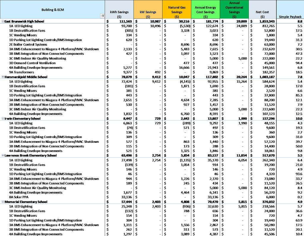
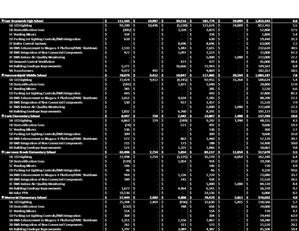
100 Page 84

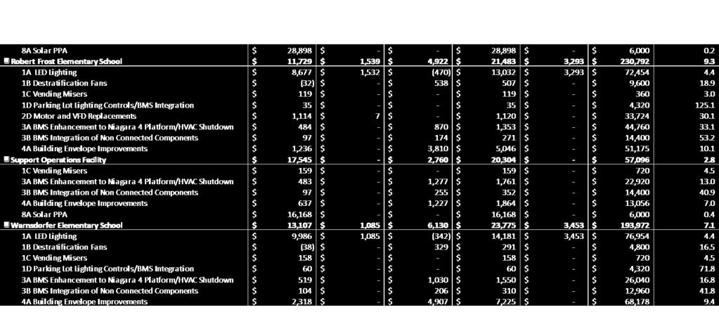
101 Page 85


102 2. Utility and Other Rebates and Incentives NJ Pay-for-Performance Program (P4P) Honeywell has been certified as a Pay for Performance Program Partner to provide technical services under direct contract to you. Acting as your energy expert, Honeywell will develop an Energy Reduction Plan for each project with a whole-building technical component of a traditional energy audit, a financial plan for funding the energy efficient measures and a construction schedule for installation. This supports your ability to take a comprehensive, whole-building approach to saving energy in your existing facilities and earn incentives that are directly linked to your savings. Eligibility Existing commercial, industrial and institutional buildings with a peak demand over 100 kw for any of the preceding twelve months are eligible to participate including hotels and casinos, large office buildings, multi-family buildings, supermarkets, manufacturing facilities, schools, shopping malls and restaurants. Buildings that fall into the following five customer classes are not required to meet the 100kW demand in order to participate in the Program: hospitals, public districts and universities, nonprofits, affordable multifamily housing, and local governmental entities. Your Energy Reduction Plan must define a comprehensive package of measures capable of reducing the existing energy consumption of your building by 15% or more to utilize the Pay Performance Program. ENERGY STAR Portfolio Manager Pay for Performance takes advantage of the ENERGY STAR Program with Portfolio Manager, EPA's interactive tool that allows facility managers to track and evaluate energy and water consumption across all of their buildings. The tool provides the opportunity to load in the characteristics and energy usage of your buildings and determine an energy performance benchmark score. You can then assess energy management goals over time, identify strategic opportunities for savings, and receive EPA recognition for superior energy performance. Incentives Incentives for the P4P program are based on the annual electric and natural gas savings produced by the Energy Conservation Measures. There are three incentives to the program; details are included in the follow page. The first incentive is distributed after a finalized project is selected and bid. This usually occurs shortly before construction starts or shortly thereafter. The second incentive is distributed a few months after construction is completed, while the third incentive is distributed usually thirteen to fourteen months after the second incentive - once a year of building usage, post-retrofit, is completed. Incentives, Rebates and Grants Summary Honeywell has a great deal of experience in applying for, and successfully securing, all available incentives, rebates and grants for our clients. We have been approved and allocated for over $9M of incentives on behalf of our New Jersey customers alone since the introduction of the Energy Savings Improvement Program legislation in The New Jersey programs employed included primarily the Office of Clean Energy s Pay for Performance and Cogeneration Incentives. Honeywell has determined that the is eligible for $1,321,619 in estimated total incentives for the projects. This includes $985,601 for the P4P program, $224,251 for the Direct Install program, and $111,766 for Permanent Load Reduction Incentives. Page 86
103 Please refer to the tables on below for a breakdown of incentive levels on a building by building basis for each type of incentive. P4P Incentives P4P Incentives Building First Second Third Total Incentive Incentive Incentive Incentive Bowne Munro Elementary School $0 $0 $0 $0 Churchill Junior High School $19,517 $77,241 $77,241 $173,999 East Brunswick High School $27,032 $164,334 $164,334 $355,700 Hammarskjold Middle School $20,364 $99,769 $99,769 $219,902 Irwin Elementary School $0 $0 $0 $0 Lawrence Brook Elementary School $5,791 $33,980 $33,980 $73,752 Robert Frost Elementary School $0 $0 $0 $0 Warnsdorfer Elementary School $0 $0 $0 $0 Administration Building $0 $0 $0 $0 Central Elementary School $5,871 $46,787 $46,787 $99,446 Chittick Elementary School $0 $0 $0 $0 Memorial Elementary School $6,212 $28,296 $28,296 $62,803 Support Operations $0 $0 $0 $0 TOTALS $84,787 $450,407 $450,407 $985,601 Permanent Load Reduction Incentives Permanent Load Reduction Incentives 1st Year 2nd Year 3rd Year 4th Year Description Incentive Incentive Incentive Incentive Permanent Load Reduction Incentives $27,942 $27,942 $27,942 $27,942 Direct Install Incentives Description 1st Year Incentive Bowne Munro Elementary School $30,782 Churchill Junior High School $0 East Brunswick High School $0 Hammarskjold Middle School $0 Irwin Elementary School $28,090 Lawrence Brook Elementary School $0 Robert Frost Elementary School $42,265 Warnsdorfer Elementary School $44,890 Administration Building $29,357 Central Elementary School $0 Chittick Elementary School $48,868 Memorial Elementary School $0 Support Operations $0 Direct Install Incentives 2nd Year 3rd Year Incentive Incentive 4th Year Incentive Page 87
104 Description 1st Year Incentive TOTALS $224,251 Direct Install Incentives 2nd Year 3rd Year Incentive Incentive 4th Year Incentive CHP Incentives Description Bowne Munro Elementary School Churchill Junior High School East Brunswick High School Hammarskjold Middle School Irwin Elementary School Lawrence Brook Elementary School Robert Frost Elementary School Warnsdorfer Elementary School Administration Building Central Elementary School Chittick Elementary School Memorial Elementary School Support Operations 1st Year Incentive 2nd Year Incentive CHP Incentives 3rd Year Incentive 4th Year Incentive TOTALS Total Rebates and Incentives Total Rebates and Incentives P4P CHP Permanent Direct Install Total Year Incentives Incentives Load Lighting Incentives Reduction Incentives Incentives Installation $84,787 $224,251 $309,039 Year 1 $450,407 $27,942 $478,349 Year 2 $450,407 $27,942 $478,349 Year 3 $27,942 $27,942 Year 4 $27,942 $27,942 TOTALS $985,601 $111,766 $224,251 $1,321,619 Page 88
105 3. Financing the ESIP In accordance with P.L.2012, c.55 an ESIP can be financed through energy savings obligations. The term refers to the two primary financing tools, debt and lease-purchase instruments. Each of these options is discussed below. Energy savings obligations shall not be used to finance maintenance, guarantees, or the required third party verification of energy conservation measures guarantees. Energy saving obligations, however, may include the costs of an energy audit and the cost of verification of energy savings as part of adopting an energy savings plan or upon commissioning. While the audit and verification costs may be financed, they are not to be considered in the energy savings plan as a cost to be offset with savings. In all cases, maturity schedules of lease-purchase agreements or energy savings obligations shall not exceed the estimated average useful life of the energy conservation measures. An ESIP can also include installation of renewable energy facilities, such as solar panels. Under an energy savings plan, solar panels can be installed, and the reduced cost of energy reflected as savings. The law also provides that the cost of energy saving obligations may be treated as an element of the local unit s utility budget, as it replaces energy costs. DEBT ISSUANCE The law specifically authorizes municipalities, school districts, cities, counties, and fire districts to issue refunding bonds as a general obligation, backed with full faith and credit of the local unit to finance the ESIP. Because an ESIP does not effectively authorize new costs or taxpayer obligations, the refunding bond is appropriate, as it does not affect debt limits, or in the case of a board of education, require voter approval. The routine procedures for refunding bonds found in the Local Bond Law and Public School Bond Law would be followed for issuance of debt, along with any required Bond Anticipation Notes as authorized pursuant to law. Regarding bonds for public schools, the Department of Education (DOE) has concluded that debt financed ESIP projects are not covered by State aid for debt service or a Section 15 EFFCA Grant as there is no new local debt being authorized. TAX-EXEMPT LEASE PURCHASE FINANCING The tax-exempt lease is a common form of financing for ESIP projects. Tax-exempt leasing is a tool that meets the basic objectives of debt, spreading the cost of financing over the life of an asset, while avoiding constitutional or statutory limitations on issuing public debt. If structured properly, by including non-appropriation language in the financing documents, the tax-exempt lease will not be considered debt for state law purposes but will be considered debt for federal income tax purposes. Thus, for federal purposes, the interest component of the lease payment is tax-exempt. Under the New Jersey Energy Savings Improvement Program (ESIP), the may authorize a lease purchase agreement between the and a financier. Ownership of the equipment or improved facilities will pass to the when all the lease payments have been made. There are legal expenses and other minimal closing costs associated with this type of structure. The lease purchase agreement may not exceed 15 years (commencing upon completion of the construction work), or 20 years where a combined heat and power or cogeneration plant is included in the project. The primary benefits of a lease are lower rates and the acquisition of essential use property without creating debt. Under a lease there is typically a single investor. The lease may have non-appropriation language that allows the East Brunswick Public Schools to access low tax exempt rates. Some previous customers have chosen to remove the non-appropriation language which has resulted in lower competitive rates. Repayment of the lease payments is tailored to meet the requirements of the. Payments are typically scheduled to commence after the construction is complete and acceptance of the project has been received by the East Brunswick Public Schools. Typically, payment terms are structured so there is no up-front capital expense to the East Brunswick Public Schools and payments are aligned within your cash flow and fiscal limits. Page 89
106 CERTIFICATES OF PARTICIPATION (COP S) Certificates of Participation are another form of a lease purchase agreement with the differentiating factor being that there are multiple investors participating in the purchase of the lease. COP s require financial disclosure and are typically utilized on higher value projects where one investor doesn t have the capacity to hold a high value lease for a single customer. ENERGY SAVINGS OBLIGATIONS Energy Savings Obligations can be issued as refunding bonds in accordance with the requirements of N.J.S.A 40A:11-4.6(c)(3). These bonds may be funded through appropriation for the utility services in the annual budget of the contract unit and may be issued as refunding bonds pursuant to N.J.S.40A:2-52 et seq., including the issuance of bond anticipation notes as may be necessary, provided that all such bonds and notes mature within the periods authorized for such energy savings obligations. Energy savings obligations may be issued either through the contracting unit or another public agency authorized to undertake financing on behalf of the unit but does not require bond referendum. Page 90

107 SECTION E MEASUREMENT & VERIFICATION AND MAINTENANCE PLAN 1. Baseline The purpose for establishing a baseline for an energy performance project is to accurately predict what the energy consumption and costs would have been as if the energy project was never completed. The baseline can then be used to measure the improvement in efficiency and determine the overall energy savings of the project. Since the energy consumption of all facilities is somewhat effected by variable weather conditions, a baseline for heating and cooling systems is typically dependent on degreedays or outside temperature. A baseline also needs to incorporate changes in facility use, such as a change in hours of operation or increased levels of outside air. Once again, if these changes would have occurred in the absence of the energy project, they should be incorporated into the project s baseline. Honeywell will calculate the baseline based on the systems and operating conditions as they currently exist. Honeywell finds baseline development most accurate if specific measurements are taken on equipment over a period of time (early in the audit phase) to determine actual kw, kwh, oil and gas consumption, cfm, gpm, hours of use, etc. A summary of some of the methods, which will be used by Honeywell to establish baselines and support, calculated savings are listed below. 1. Spot measurements of electrical loads such as lighting, fan and pump motors, chillers, electric heat, etc. 2. Measurement of equipment operating hours using electric data recorders. 3. Measurement of existing operating conditions using data recorders for space temperature and humidity, air handler temperatures (mixed, return, cooling and heating coil discharges), and space occupancy using lighting loggers. 4. Spot measurement for boiler efficiencies, water use. 5. Running measurements of chiller operation, including simultaneous measurement of input kwh or steam flow, and chilled water supply and return temperatures and flow (gpm). 6. Records of operating conditions from building management systems and utility-grade meters. The data from the above is used to calculate existing energy use, which is then reconciled with current facility utility bills, and adjusted as required to provide a mutually agreed baseline. To provide valid savings evaluations, Honeywell s maintains a significant inventory of metering equipment utilized by its auditors and Energy Engineers to ascertain critical data about the operation of the facility. Typically, Honeywell s auditors use the following equipment for their onsite measurements: 1. Recording and instantaneous power and harmonic analyzers. 2. Data loggers for pressures, temperatures, flow rates, humidity and CO2. 3. Lighting level and recording profile/run-hour and occupancy meters. 4. Multimeters, hand held kw meters. 5. Combustion analyzers. 6. Ultrasonic flow meters. 7. Infrared thermometers The ECMs installed in many projects allow for energy savings to be identified by direct metering or a combination of metering and calculations with accepted assumptions. In the case of lighting, for example, it is relatively easy to meter representative samples of unique fixture types, both before and after a retrofit, to determine the power consumption difference in Watts. When multiplied Page 91
108 by the quantity of each fixture type, the total connected load reduction can be derived. In combination with run time assumptions, or meters, the electrical reduction can be accurately determined. Where possible, direct measurement of ECMs during construction (before and after the retrofit) coupled with energy savings calculations is a method the Honeywell finds to be very accurate and cost-effective. Due to the nature of some ECMs, or when a combination of ECMs is installed, individual (discrete) metering may not be either possible or able to fully document a baseline and calculate savings. Many of these situations can be handled by combining results from metering along with either engineering-based calculations or output from nationally recognized building simulation programs such as DOE II, ASEAM, TRACE or HAP. This method would be used for ECMs such as night setback, and where no other ECMs have significant interaction with the setback measure. Formulas exercised in energy savings calculations follow the laws of physics, and many are included in the ASHRAE Handbook of Fundamentals. However, such calculations (i.e. equipment operation profiles) must be tempered by experience, past retrofit practice, and expectations of future operating conditions to arrive at achievable values in practice. Honeywell always reviews each and every project, in detail, for the anticipated savings and never hesitates to reduce the anticipated energy calculations where experience dictates necessary. The final result is a coupled project where the final savings are equal to or greater than anticipated. Calculating the units of energy saved is a critical measure of energy efficiency improvements, but it does not indicate the actual dollars saved. To do this, Honeywell and the will establish the base rates that will act as "floor" rates in calculating the savings. These are usually the rates that are in effect at the time of the start of the contract or rates used for audit estimated savings. 2. Adjustment to Baseline Methodology 1 Honeywell s methodology for establishing and adjusting the baseline is determined by the characteristics of the facility, the conservation technology being installed, the technology being replaced, the type of measurement and verification the East Brunswick Public Schools requires and the needs of the for future changes in facility use. The purpose of this flexible approach is to make the most accurate possible measurement of the changes in energy uses that are specifically attributable to Honeywell installed ECMs. This creates the ability over the life of the contract to continue measuring only savings achieved by Honeywell and leaves the free to make future changes to the building or systems without affecting the savings agreement. It also necessitates fewer provisions for making adjustments to the baseline. Modifications to the energy baseline or savings will be made for any of the following: 1. Changes in the number of days in the annual review cycle. 2. Changes in the square footage of the facilities. 3. Changes in the operational schedules of the facilities. 4. Changes in facility indoor temperatures. 5. Significant changes in climate. 6. Significant changes in the amount of equipment or lighting utilized in the facility. Examples of situations where the baseline needs to be adjusted are: i) changes in the amount of space being air conditioned, ii) changes in auxiliary systems (towers, pumps, etc.) and iii) changes in occupancy or schedule. If the baseline conditions for these factors are not well documented it becomes difficult, if not impossible, to properly adjust them when they change and require changes to payment calculations. To compensate for any addition and deletion of buildings and impact on the baseline model, Honeywell will use sound technical methodologies to adjust the baseline. An example would be to add or delete building energy impact via the calculated cooling load in tons as a percentage of the existing campus tonnage baseline or use indices like W/ft 2 and Btu/ft 2 to calculate the energy consumption of the building and then add or subtract the energy usage to or from the baseline energy consumption. 1 The energy baseline modifications shall use commonly accepted energy engineering methods that are mutually agreeable to both Honeywell and customer. Should agreement on these methods, including the climate adjustments, not be reached between Honeywell and customer, both parties could appeal to an independent engineering. Page 92
109 3. Energy Savings Calculations In calculating energy savings, Honeywell s highly experienced audit staff uses onsite surveys and measurements, National Oceanic and Atmospheric Administration weather data, detailed discussions with the client s operations and maintenance personnel and engineers, utility records, and other sources to ensure accurate energy, water and O&M savings. Typically, the following data is gathered: 1. Local weather data. 2. Utility bills and sub-metered consumption trends. 3. Utility rate structure. 4. Facility use and occupancy data. 5. Internal equipment loads. 6. Interviews of operations and maintenance staff and management. 7. Building construction, age, use and layout. 8. Schematics of energy and water distribution systems. 9. Identification and inventory of HVAC equipment. 10. Identification and inventory of process equipment. 11. Design, configuration and operating characteristics of HVAC systems. 12. Design, configuration and operating characteristics of process systems. 13. Control strategies and sequences of operation for HVAC and other process equipment. 14. Identification and count of all lighting fixtures and determination of power consumption for each type. 15. Identification and inventory of lighting control methods. 16. Measurement of foot-candle levels at sample locations. 17. Power quality and harmonics, power factor. 18. Indoor air quality issues. Calculating the units of energy saved is a critical measure of energy efficiency improvements, but it does not indicate the actual dollars saved. To do this, Honeywell and the will establish the base rates that will act as "floor" rates in calculating the savings. These are usually the rates that are in effect at the time of the start of the contract or rates used for audit estimated savings. The equation below will be used to calculate the annual savings in dollars. 12 AnnualSavings($) = { ( RatekWh, Base kwhsaved, m ) + ( Rate ( Rate where: Steam, Base m= 1 Steam Saved, klbs, m ) + ( Rate NG NG RatekWh,Base= defined base rate for kwh consumption kwhsaved,m= calculated kwh savings for month m Saved, MCF, m RateFuel Oil, Base= defined base rate for fuel Oil savings (XX/gal.) Fuel OilSaved,m= calculated chilled water savings in gal. for month m )} + Agreed($) Saved, gal, m Honeywell assigns dollar values to the true incremental value of savings for energy and water. In other words, we do not combine for example, demand and consumptions numbers so that there is an average value to savings. Honeywell looks at each incremental rate to units saved to properly determine the value (dollar) to the or real bill reductions. As noted in the RFP energy escalation rates will be established in accordance with New Jersey Board of Public Utility guidelines. fuel Oil RateSteam,Base= defined base rate for steam consumption ($XX/MMBtu.) SteamSaved,m= calculated Steam savings in MMBtu. for month m RateNG,Base= defined base rate for natural gas consumption ($XX/Therm) NGSaved,m= calculated natural gas savings in Therms for month m Agreed($)= Annual savings in dollars (water, sewer, maintenance, etc.), Base Fuel Oil ) + Page 93
110 Based on this, Honeywell will review all utility bills (hourly data), tariffs, special contracts and commodity contracts to develop the incremental value (costs) of each utility. The O&M savings is typically a function of existing the East Brunswick Public School's budgets (labor & direct costs), maintenance contracts and operations (supplier) contracts. Honeywell will analyze the information to provide a conservative savings representation for the East Brunswick Public School's review and acceptance. The information will include all calculations and assumptions. 4. Measurement & Verification The purpose of performing any monitoring and verification is to establish an agreed upon process that provides the customer both a level of satisfaction that the improvements have been delivered and ongoing information as to their operation and performance. Additionally, this effort will be used to assess the actual dollars of savings versus the guarantee level. It is essential for the success of this program that Honeywell and the agree on a mutually acceptable methodology for measuring and verifying energy savings that are attributable to the energy conservation measures (ECMs) Honeywell installs. This M&V plan provides the procedures to document the energy and cost savings of each of the proposed ECMs. The plan for monitoring and verifying energy savings for the proposed ECMs is based on the methods described in the International Performance Measurement and Verification Protocol (IPMVP) 2. Our approach to M&V is directly consistent with, and in compliance with, the IPMVP. This protocol provides a framework for the most widely accepted and used M&V methods by the industry. Engineering calculations of energy and cost savings for the project are based on operating parameters (such as weather, temperature settings, run hours, occupancy patterns, and space usage) and equipment performance characteristics. The M&V plan uses the operating parameters established in the baseline for all savings calculations during the term of the project. The intent of the M&V plan is to verify that the ECMs installed by Honeywell will provide the expected energy savings. Therefore, Honeywell will collect data and relative information during the post-retrofit period to demonstrate that the installed equipment is performing at expected levels. It is assumed that the will continue to be a dynamic institution adding or renovating buildings and desiring to retain the right to set comfort and operating characteristics. To accommodate this, Honeywell will develop its M&V plan in a way that allows the to adapt to the demands of future campus growth and changes without the need for the and Honeywell to negotiate energy baseline adjustments. Our typical M&V plan will utilize broadband Internet access to the appropriate the East Brunswick Public School's control interfaces to both confirm operating status and to download trend data to verify proper equipment maintenance. One year after the commencement date of the ECMs, Honeywell will submit a report verifying and calculating the energy and cost savings for the first year. This report will be submitted for facility review and approval. For the remaining contract term, Honeywell will provide annual reports. These reports will include results of inspections of the installed equipment/systems, energy and cost savings, and recommendations to provide optimum energy performance. The following table lists the information concerning typical M&V equipment used: Instrument Make Power Multi-meter Fluke 39 Light Meter Osram or Phillips Portable Temperature/Humidity Multi-meter TSI Retractable Insertion Vortex Flow meter Hydro-Flow Model 3100 BTU Meter Hydro-Flow BTU-121 BTU/Energy Measurement System KW/KWH Transducers Veris Industries (H6000 SERIES) 2 Page 94

111 All permanent measurement equipment will be purchased new with a calibration certificate from the manufacturer. The power multi-meter and the TSI multi-meter will be calibrated annually before using them in the annual inspection. General Approach to M&V Energy and water savings are determined by comparing the energy and water use associated with a facility or certain systems within a facility before and after the installation of an ECM or other measure. The before case is the baseline. The after case is the post-installation or performance period. Baseline and post-installation energy use measurements or estimates can be constructed using the methods associated with M&V options A, B, C, and D, as described in the IPMVP. The challenge of M&V is to balance M&V costs, accuracy, and repeatability with the value of the ECM(s) or systems being evaluated, and to increase the potential for greater savings by careful monitoring and reporting. M&V Options The IPMVP guidelines classify the M&V procedures into four categories, Options A, B, C and D. As shown in the table below, these options differ in their approach to the level of complexity of the M&V procedures. M&V Option Option A Verifying that the measure has the potential to perform and to generate savings. Option B Verifying that the measure has the potential to perform and verifying actual performance by end use. Option C Verifying that the measure has the potential to perform and verifying actual performance (whole building analysis.) Option D Verifying actual performance and savings through simulation of facility components and/or the whole facility Performance Verification Techniques Option A is appropriate for ECMs that have energy use that can be readily quantified, such as the use of high efficiency lighting fixtures, high efficiency constant speed motors, and other standard engineering calculations. Engineering calculations before and after installation spot measurements and use of EMS data points with stipulated values. Option B is appropriate for ECMs that require periodic or on-going measurements to quantify energy use; such as the use of variable frequency drives on pump or fan motors. Engineering calculations with metering and monitoring strategy throughout term of the contract. Option C is used for ECMs for which the energy use or energy savings cannot be measured directly, such as building envelope modifications. Option C is based on the use of utility meters to quantify building energy use. Utility meter billing analysis-using techniques from simple comparison to multivariable regression analysis. Option D is used for ECMs for which the energy use or energy savings cannot be measured directly, or savings for individual ECMs are heavily interdependent. Calibrated building simulation is used to separate the energy savings attributable to each ECM. Calibrated energy simulation/modeling; calibrated with hourly or monthly utility billing data and/or enduse metering. Option A is appropriate for ECMs that have energy use that can be readily quantified, such as the use of high efficiency lighting fixtures, high efficiency constant speed motors, and other standard engineering calculations. Option B is appropriate for ECMs that require periodic or on-going measurements to quantify energy use; such as the use of variable frequency drives on pump or fan motors. Option C is used for ECMs for which the energy use or energy savings cannot be measured directly, such as building envelope modifications. Option C is based on the use of utility meters to quantify building energy use. Option D is used for ECMs for which the energy use or energy savings cannot be measured directly, or savings for individual ECMs are heavily interdependent. Calibrated building simulation is used to separate the energy savings attributable to each ECM. In general, Page 95
112 ECM Energy Savings = Baseline Energy Use - Post-Installation Energy Use And Energy Cost savings ($) = Total Energy Savings x Contractual Energy Rates Exceptions to this simple equation are as follows: Projects where an on/off M&V method is used. For example, after a new energy management system is installed, control features are turned off for a set period of time to recreate baseline conditions. Thus, savings are determined after installation by comparing energy use with and without the control features activated. Since energy use at a facility is rarely, if ever, constant, another way to define M&V is as a comparison of a facility s post-installation energy use with its usage if the ECM or system had not been installed. This takes into account situations in which baseline energy use must be adjusted to account for changing conditions, such as changes in facility operation, occupancy, or use or external factors such as weather. Post-Retrofit M&V Activities There are two components associated with M&V of performance contract projects: 1. Verifying the potential of the ECM to generate savings also stated as confirming that the proper equipment/systems were installed, are performing to specification and have the potential to generate the predicted savings. 2. Determining/verify energy savings achieved by the installed ECM(s). Verifying the Potential to Generate Savings Verifying baseline and post-installation conditions involves inspections (or observations), spot measurements, and/or commissioning activities. Commissioning includes the following activities: Documentation of ECM or system design assumptions Documentation of the ECM or system design intent for use by contractors, agencies and operators Functional performance testing and documentation necessary for evaluating the ECM or system for acceptance Adjusting the ECM or system to meet actual needs within the capability of the system Post-Installation Verification Post-installation M&V verification will be conducted by both Honeywell and the Client to ensure that the proper equipment/systems that were installed are operating correctly and have the potential to generate the predicted savings. Verification methods may include surveys, inspections, and/or spot or short-term metering. Regular Interval Post-Installation Verification At least annually, Honeywell will verify that the installed equipment/systems have been properly maintained, continue to operate correctly, and continue to have the potential to generate the predicted savings. Savings report for all the installed ECMs will be submitted each year after the acceptance date of the work performed by Honeywell. Computation of Energy Savings After the ECMs are installed, energy and cost savings will be determined annually by Honeywell in accordance with an agreedupon M&V approach, as defined in a project-specific M&V plan. Construction/Interim Savings Construction or Interim savings are usually measured by using the same methodology as described in the detail M&V plan for each ECM. The start and the completion time for each ECM must be agreed to between Honeywell and the East Brunswick Public Schools. Page 96
113 Electricity and thermal savings from the ECMs where no detailed long-term data is required to be collected will be stipulated and will be based on the starting and the final completion dates and verification of the operation of the ECMs. For other ECMs where long-term data collection is required by the M&V plan, data will be used to calculate the savings using the same equations as described in the detail plan. For example, to calculate electricity savings for the installation of a VFD, the kw is spot measured at a set speed for selected motors through a sampling plan. The measured kw is subtracted from the baseline kw to calculating the savings. Thermal savings are tied to the electrical savings in the manner described in the detail M&V plan. The results are extrapolated to cover all the VFDs installed by Honeywell. The savings for each of the monitored VFD is calculated on an interval basis as follows: kwsaved = (kwbase kwspot Measured) kwhsaved = Estimated operating hours during the interim period * kwsaved The total kwh savings is the sum of the kwhsaved for all the installed VFDs. Page 97
114 5. Site Specific M&V Plan ECM # and Name EC M 1A LED Lighting EC M 1B - De- Stratification Fans E C M 1C Vending Misers ECM 1D Parking Lot Lighting C o ntrols/b M S Integration Summary of ECM Upgrade Lighting systems: Re-lamp/Re- ballast T- 8 to LED New Fixtures Incandescent to LED M etal Halide and Sodium Vapor to LED High Bays Install De- Stratification fans in Gymnasiums, Cafeterias and Auditoriums to minimize stratification of hot air and m aintain hot air flow below the fan level Install Vending machine energy management devices Upgrade Lighting systems: Install lighting controls and integrating to B M S System Measurement and Verification Methodology / Recommendation O ption A: Pre and Post measurements Line by Line scope and engineering calculations O ption C: Fuel Savings Utility Bill Co m p arison for all fuel related measures O ption A: Pre and Post measurements Line by Line scope and engineering calculations O ption A: Pre and Post measurements Line by Line scope and engineering calculations Description of M&V Pre and Post Process Pre- M &V: M e asure ment of K W for 5% sa m ple fixtures in each category Data log usage hours Data Log occupancy schedules Update Line by Line scope with measured KW and usage hours P ost M& V: M e asure ment of K W for 5% sa m ple fixtures in each category Usage Hours to remain same Occupancy schedules to remain same Energy Savings: Update Line by Line scope with measured KW and usage hours and co mpare to pre- retrofit calculated savings Pre- M &V: V erify para meters used in engineering calculations with equip ment na me plate data and savings assumptions P ost M& V: F uel: Compare post installation M&V fuel cost based on fuel billing data and Metrix tuned to normalize to heating degree days Pre- M &V: Measurement of KW for 5% sample machines in each category Data log usage hours Data Log occupancy schedules Update Line by Line scope with measured KW and usage hours P ost M& V: Measurement of KW for 5% sample machines in each category Usage Hours to remain same Energy Savings scope with measured K W and usage hours and compare to pre- retrofit calculated savings Pre- M &V: Measurement of K W for 5% sa m ple fixtures in each category Data log usage hours Data Log occupancy schedules Update Line by Line scope with measured KW and usage hours P ost M& V: M e asure ment of K W for 5% sa m ple fixtures in each category Page 98
115 ECM # and Name Summary of ECM Measurement and Verification Methodology / Recommendation Description of M&V Pre and Post Process Usage Hours to remain same Occupancy schedules to remain sa me Energy Savings: Update Line by Line scope with measured KW and usage hours and ECM 2A Boiler Replacements Replace boilers in select locations in kind to handle base load O ption C: Utility Bill Comparison for all fuel related measures co mpare to pre- retrofit calculated savings Pre- M &V: Baseline annual fuel cost based on fuel billing data and Metrix tuned to normalize to heating degree days Perform combustion efficiency test on boilers P ost M& V: Co mpare post installation M&V fuel cost based on fuel billing data and Metrix tuned to ECM 2B Domestic Hot Water Replacements ECM 2C - Rooftop Unit Replacement Replace existing domestic hot water heater with condensing natural gas domestic hot water heater Replace antiquated Roof Top Units with new high efficiency VFD equipped Rooftop Units Option C: Utility Bill Comparison for all fuel related measures O ption A: Engineering calculations based on nameplate and manufacturer supplied data for the existing and replacement units normalize to heating degree days Perform efficiency test on replaced boilers to insure operating conditions are maintained Pre-M&V: Baseline annual fuel cost based on fuel billing data and Metrix tuned to normalize to heating degree days Perform combustion efficiency test on boilers Post M&V: Compare post installation M&V fuel cost based on fuel billing data and Metrix tuned to normalize to heating degree days Perform efficiency test on replaced boilers to insure operating conditions are maintained Pre- M &V: Verify manufacturer provided data for existing unit efficiency (SEE R) P ost M& V: Verify manufacturer provided data for new condensing unit (SEER) verify the new equipment and controls are installed and commissioned as recommended by manufacturer ECM 2D - Premium Efficiency Motors and VFDs ECM 2E Boiler Controls Install Variable Frequency Drives on hot water and chilled water pumps to operate the pump motors in response to the system load. Replace antiquated motors with new premium efficiency motors Install Burner Controls to improve combustion efficiency O ption A: Engineering calculations for variable frequency drives following pump affinity laws. Engineering calculations based on nameplate and manufacturer supplied data for the existing and replacement motors O ption C: Utility Bill Comparison for all fuel related measures Pre- M &V: Verify manufacturer provided data for the pu mp performance data and motor efficiencies. P ost M& V: O btain trend data for VF D operation from the B M S system to verify baseline calculation assumptions on system loads Verify efficiency of new motors Verify manufacturer provided data for new chiller efficiency (kw/ton) verify the new equipment and controls are installed and commissioned as recommended by manufacturer Pre M& V: Baseline annual fuel cost based on fuel billing data and Metrix tuned to normalize to heating degree days Page 99
116 ECM # and Name Summary of ECM Measurement and Verification Methodology / Recommendation Description of M&V Pre and Post Process Perform combustion efficiency test on boilers P ost M& V: Compare post installation M&V fuel cost based on fuel billing data and Metrix tuned to normalize to heating degree days Perform efficiency test on replaced boilers to insure operating conditions are maintained E C M 2F - Install control devices on O ption A: Pre- M &V: Kitchen Hood the Kitchen hoods to E ngineering calculations for variable Verify manufacturer provided data for the motor performance data and motor efficiencies. C o ntrols control exhaust air in frequency drives following affinity P ost M& V: response to the cooking laws. O btain trend data for VF D operation from the B M S system to verify baseline calculation load. Replace fan motors Engineering calculations based on assumptions on system loads with new pre miu m nameplate, manufacturer supplied Verify efficiency of new motors efficiency motors and VF D data and operating hours for the drives existing and replacement motors EC M 2G Install control device on O ption A: Pre- M &V: W alk- In walk- in freezer and Stipulated Engineering calculations None Freezer/Cooler refrigerator evaporators to based on case studies for the P ost M& V: C o ntrollers shut down the fan motor Intellidyne control Savings stipulated based on engineering calculations for the term of contract when the compressor is off on duty cycle E C M 2H Replace Ice Rink Chiller Option A: Engineering calculations Pre- M &V: C hiller serving Rink 1 at Arena based on nameplate and Verify manufacturer provided data for existing unit efficiency (SEER) and recoverable Heat Replacement m anufacturer supplied data for the Rate (HR) existing and replacement heat P ost M& V: C hillers V erify manufacturer provided data for new Chiller unit (SEE R) verify the new equipment ECM 2I Booster Heater Conversion Convert Electric Dish Washer Booster Heater to Gas Option A: Engineering calculations based on nameplate and manufacturer supplied data for the existing and replacement Heaters and controls are installed and com missioned as reco m mended by m anufacturer Pre- M &V: Verify manufacturer provided data for existing unit k W. P ost M& V: Verify manufacturer provided data for new Heater kw verify the new equipment and controls are installed and commissioned as recommended by manufacturer Option C: Utility Bill Comparison for all fuel related measures Pre-M&V: Baseline annual fuel cost based on fuel billing data and Metrix tuned to normalize to heating degree days Post M&V: Compare post installation M&V fuel cost based on fuel billing data and Metrix tuned to normalize to heating degree days Page 100
117 ECM # and Name Summary of ECM Measurement and Verification Methodology / Recommendation Description of M&V Pre and Post Process E C M 2J Add Standby Generator to O ption C: Utility Bill C o m p aris o n for Pre- M &V: Standby building for back- up power. all fuel related measures Baseline annual fuel cost based on fuel billing data and Metrix tuned to normalize to heating G enerator degree days P erfor m combustion efficiency test on boilers P ost M& V: Compare post installation M&V fuel cost based on fuel billing data and Metrix tuned to normalize to heating degree days ECM 2K Convert PEF to ERU Convert Power Exhaust to Energy Recovery Option A: Engineering calculations based on Bin data for the existing and replacement Units Perform efficiency test on replaced boilers to insure operating conditions are maintained Pre- M &V: V erify Bin data and cooling use for existing equipment P ost M& V: Verify Bin and cooling use for new equipment. Option C: Utility Bill Comparison for all fuel related measures Pre-M&V: Baseline annual fuel cost based on fuel billing data and Metrix tuned to normalize to heating degree days Post M&V: Compare post installation M&V fuel cost based on fuel billing data and Metrix tuned to normalize to heating degree days E C M 3 - Upgrade Building O ption A: Pre- M &V: Building Management Systems to Electric energy savings - Verify existing operating parameters match the baseline calculation assumptions Management D D C a n d integrate all Engineering calculations based on P ost M& V: Syste m systems to a central program med parameters. Verify that systems are installed as specified and controls are programmed to match the Upgrades - 3A platform such that the O ption C: savings assumptions - Niaga ra systems may be Fuel Savings Electric Energy: Platform m onitored and controlled Utility Bill Co m p arison for all fuel Verify savings based on programmed parameters and engineering calculations Enhancements as program med to related measures F uel:, 3 B m aintain global settings Compare post installation M&V fuel cost based on fuel billing data and Metrix tuned to Integration of such as night set back, normalize to heating degree days Non- opti mu m stop- start etc. Connected Components, 3C BMS IAQ M onitoring ECM 3D Install CO2 sensor O ption A: Pre- M &V: Demand controls to limit OA based Electric energy savings - Verify existing operating parameters match the baseline calculation assumptions C o ntrol on occupancy of space Engineering calculations based on P ost M& V: Ventilation program med parameters. Page 101
118 ECM # and Name Summary of ECM Measurement and Verification Methodology / Recommendation Description of M&V Pre and Post Process O ption C: Verify that systems are installed as specified and controls are progra m m ed to match the Fuel Savings savings assumptions Utility Bill Co m p arison for all fuel Electric Energy: related measures Verify savings based on programmed parameters and engineering calculations F uel: Compare post installation M&V fuel cost based on fuel billing data and Metrix tuned to normalize to heating degree days EC M 4A - Install we ather stripping O ption A: Pre- M &V: Building on doors, seal roof wall Electric energy savings - V erify para meters used in engineering calculations with site conditions Envelope joints and roof Engineering calculations based on P ost M& V: Improvements penetrations program med parameters. F uel: O ption C: Compare post installation M&V fuel cost based on fuel billing data and Metrix tuned to Fuel Savings normalize to heating degree days Utility Bill C o m p ariso n for all fuel related measures EC M 4B - R eplace existing Roofs O ption A Pre- M &V: R oof with ne w energy efficient Electric energy savings - V erify para meters used in engineering calculations with site conditions Replacements R oofs Engineering calculations based on P ost M& V: program med parameters. F uel: O ption C: Compare post installation M&V fuel cost based on fuel billing data and Metrix tuned to Fuel Savings normalize to heating degree days Utility Bill Co m p arison for all fuel related measures ECM 5 A Install control software to O ption A: Pre- M &V: Co mputer ensure desktop computers Stipulated Engineering calculations None Po wer Management EC M 6A Co mbined H e at & Po w er (CHP) revert to sleep mode when not being used. Install Cogeneration units based on computer power manage ment Manf. Software infor m ation. Option A Engineering calculations based on nameplate and manufacturer supplied data for the cogeneration units and - engineering calculations based on programmed parameters. Option C Utility Bill Comparison for all fuel related measures P ost M& V: Savings stipulated based on engineering calculations for the term of contract Pre-M&V: Baseline annual fuel cost based on fuel billing data and Metrix tuned to normalize to heating degree days Perform combustion efficiency test on boilers V erify para meters used in engineering calculations with site conditions Post M&V: Compare post installation M&V fuel cost based on fuel billing data and Metrix tuned to normalize to heating degree days Perform efficiency test on replaced boilers to insure operating conditions are maintained Page 102
119 ECM # and Name Summary of ECM Measurement and Verification Methodology / Recommendation Description of M&V Pre and Post Process EC M 7A - Participate in PJM N/A Pre- M &V: Permanent permanent load reduction N/A Load program P ost M& V: Reduction N/A EC M 8A Install roof mounted solar N/A Pre- M &V: Utilize baseline kwh consumption determine kwh produced Solar PPA P V arrays Post M&V: Measure and Provide a report of the kwh generated ECM 9 A Replace existing O ption A: Pre- M &V: Transform er secondary transformers Engineering calculations based on Measure typical existing transformer (typical one for each size) input and output KW to Upgrades with high efficiency increase in transformer efficiency establish transformer losses equivalents P ost M& V: M easure input and output K W for new transformer (typical one for each size) Verify savings with engineering calculations Page 103
120 6. Guarantee of Savings The approach that Honeywell utilizes in this asset management program includes two key components: a performance guarantee and financial savings. Honeywell guarantees the that all installations and work performed are subject to final inspection and the East Brunswick Public School's acceptance. This procedure ensures all work will be to the level of quality the expects. Honeywell also guarantees it will meet the objectives mutually defined with the. Honeywell takes its commitment to partner with the for the life of the contract seriously, and looks forward to a successful, long-term partnership. Honeywell considers the guarantee to be the cornerstone of our service to you. To be considered a performance contract an energy guarantee is an optional component under the New Jersey Energy Savings Improvement Program (ESIP) legislation. The basis of an energy performance contract is that the majority of risk is shifted from the to the ESCO. The strength of the Guarantee is only as good as the Company backing it and their financial solvency. With over $39 Billion in assets, Honeywell has the financial strength and background to support the for the long term. Savings Guarantee: With the understanding that the must maintain fiscal health and accountability, Honeywell can financially guarantee the results of its programs and clearly support this obligation with the commitment to regular review of program results and reconciliation. Honeywell's financial strength and stability give it the ability to extend a FIRST- PARTY GUARANTEE to the. A first party guarantee eliminates the risk on the East Brunswick Public Schools and places it directly onto Honeywell. This differs from some other ESCO s who provide a thirdparty guarantee, which insulates them from the owner through the use of insurance instruments. If at the end of any year the program has not met or exceeded the guaranteed savings for that year, Honeywell will refund the difference between the guaranteed amount and what was actually saved. For all equipment covered by the Energy Savings Guarantee, the shall be responsible for on-going maintenance and component replacement in accordance with manufacturer s standards. The customer will also be responsible for operating the equipment in accordance with manufacturer s specifications. Honeywell will develop savings methodologies that follow current industry practice, such as outlined by the New Jersey Board of Public Utilities (BPU) and Federal Energy Management Program s (FEMP) M&V Guidelines: Measurement and Verification for Federal Energy Projects. References to M&V protocols from the International Performance Measurement and Verification Protocol (IPMVP), ASHRAE Guideline 14 and the Air-Conditioning Refrigeration Institute (ARI) are used to further qualify the M&V plan. As stated above, under the New Jersey ESIP legislation acceptance of a performance guarantee is optional at the East Brunswick Public Schools sole discretion. In the same way, the duration of the guarantee is also optional. Many of Honeywell s New Jersey customers have elected to keep the guarantee in force for less than the total performance periods, i.e. three (3) to five (5) years. Others have elected to accept a one (1) year guarantee, while reserving the option to renew for additional years after they have had the opportunity to review the track record of actual savings results. Obviously, this a very customer specific decision based on the risk management culture of each unique organization. The key point is that Honeywell is flexible with regard to the structure and duration of the guarantee. The final terms will be discussed and defined as part of our co-authored ESIP project. Solely for informational purposes, it is worth noting that if the does elect to accept a guarantee, New Jersey ESIP law requires that the contract with a third-party independent firm to verify that the energy savings are realized. To preserve the independent status of this contractor these costs are required to be incurred directly by the. The RFP requires that the cost of the guarantee be identified during this response phase. Honeywell develops and implements every project with the same high level of detail and confidence and therefore will always provide a Savings Guarantee at no additional cost. However, if the opts to accept the Savings Guarantee, an annual cost of $60,000 will be applicable to account for on-going Honeywell service costs incurred during the measurement and verification of the savings as indicated in Form V of our RFP response. Page 104

121 All guarantees require that the owner maintain the system in accordance with the manufacturer s specifications. Regardless of guarantee acceptance, ongoing maintenance as recommended by the BPU, Honeywell and / or manufacturer specifications is required to achieve the projected energy savings. Maintenance should also include a periodic verification of the system to make sure the maintenance is properly conducted and the system is meeting the original specifications and design. 7. Recommended Preventive Maintenance Services A Comprehensive Portfolio, a Customized Approach. Honeywell offers a uniquely comprehensive portfolio of services one of the most extensive in the industry. As part of the, we recommend the following services for consideration to ensure achievement of the Energy Savings outlined in this plan Per the NJ ESIP program, all services are required to be bid by the for services as desired. Based on Honeywell s vast service organization, we are uniquely qualified to develop design specification for the public bidding per NJ Law. Honeywell strongly believes that the long-term success of any conservation program is equally dependent upon the appropriate application of energy savings technologies, as well as solid fundamental maintenance and support. One of the primary contributors to energy waste and premature physical plant deterioration is the lack of operations, personnel training and equipment maintenance. Honeywell recommends routine maintenance on the following systems throughout the for the duration of an energy guarantee of savings Maintenance, Repair and Retrofit Services: Mechanical Systems Building Automation Systems Temperature Control Systems Air Filtration Honeywell will work with the to evaluate current maintenance practices and procedures. This information will be the basis of a preventive maintenance and performance management plan designed to maximize building operating efficiencies, extend the useful life of your equipment and support the designed. At a minimum, we recommend the following tasks be performed on a quarterly basis with the Wide Building Management System. System Support Services 1. Review recent mechanical system operation and issues with customer primary contact, on a monthly basis. 2. Review online automation system operation and event history logs and provide summary status to the customer primary contact. Identify systemic or commonly re-occurring events. 3. Check with customer primary contact and logbook to verify that all software programs are operating correctly. 4. Identify issues and prioritize maintenance requests as required. 5. Provide technical support services for trouble shooting and problem solving as required during scheduled visits. 6. Provide ongoing system review and operations training support; including two semi-annual lunches and learn sessions. 7. Establish dedicated, site-specific emergency stock of spare parts to ensure prompt replacement of critical components. These will be stored in a secure location with controlled access. Page 105
122 Configuration Management 1. Update documentation and software archives with any minor changes to software made during maintenance work. 2. Verify and record operating systems and databases. 3. Record system software revisions and update levels. 4. Archive software in designated offsite Honeywell storage facility, on an annual basis. 5. Provide offline software imaging for disaster recovery procedures, updated on a regular basis. Front End / PC Service 1. Verify operation of personal computer and software: 2. Check for PC errors on boot up 3. Check for Windows errors on boot up 4. Check for software operations and performance, responsiveness of system, speed of software 5. Routinely backup system files, on an annual basis: 6. Trend data, alarm information and operator activity data 7. Custom graphics and other information 8. Ensure disaster recovery procedures are updated with current files 9. Clean drives and PC housing, on an annual basis: 10. Open PC and remove dust and dirt from fans and surfaces 11. Open PC interface assemblies and remove dust and dirt 12. Clean and verify operation of monitors. 13. Verify printer operation, check ribbon or ink. 14. Initiate and check log printing functions. 15. Verify modem operation (if applicable). 16. Review IVR schedule for alarms and review (if applicable). Temperature Controls UNIT VENTS Services Performed Annual Inspection 1. Inspect motor and lubricate. 2. Lubricate fan bearings. 3. Inspect coil(s) for leaks. 4. Vacuum interior. 5. Test operation of unit controls. PUMPS Services Performed Preseason Inspection 1. Tighten loose nuts and bolts. 2. Check motor mounts and vibration pads. 3. Inspect electrical connections and contactors. Seasonal Start-up 1. Lubricate pump and motor bearings per manufacturer s recommendations. 2. Visually check pump alignment and coupling. 3. Check motor operating conditions. 4. Inspect mechanical seals or pump packing. 5. Check hand valves. Mid-season Inspection 1. Lubricate pump and motor bearings as required. 2. Inspect mechanical seals or pump packing. 3. Ascertain proper functioning. Page 106
123 Seasonal Shut-down 1. Switch off pump. 2. Verify position of hand valves. 3. Note repairs required during shut-down. PACKAGED AIR-CONDITIONING SYSTEMS Services Performed Preseason Inspection 1. Energize crankcase heater. 2. Lubricate fan and motor bearings per manufacturer s recommendations. 3. Check belts and sheaves. Adjust as required. 4. Lubricate and adjust dampers and linkages. 5. Check condensate pan. Seasonal Start-up 1. Check crankcase heater operation. 2. Check compressor oil level. 3. Inspect electrical connections, contactors, relays, operating and safety controls. 4. Start compressor and check operating conditions. Adjust as required. 5. Check refrigerant charge. 6. Check motor operating conditions. 7. Inspect and calibrate temperature, safety and operational controls, as required. 8. Secure unit panels. 9. Pressure wash all evaporator and condenser coils (if applicable) 10. Log all operating data. Mid-season Inspection 1. Lubricate fan and motor bearings per manufacturer s recommendations. 2. Check belts and sheaves. Adjust as required. 3. Check condensate pan and drain. 4. Check operating conditions. Adjust as required. 5. Log all operating data. Seasonal Shut-down * 1. Shut down per manufacturer s recommendations. * If no Shut-down is required then (2) Mid-season Inspections are performed BOILERS Services Performed Preseason Inspection 1. Inspect fireside of boiler and record condition. 2. Brush and vacuum soot and dirt from flues (not chimneys) and combustion chamber. 3. Inspect firebrick and refractory for defects. 4. Visually inspect boiler pressure vessel for possible leaks and record condition. 5. Disassemble, inspect and clean low-water cutoff. 6. Check hand valves and automatic feed equipment. Repack and adjust as required. 7. Inspect, clean and lubricate the burner and combustion control equipment. 8. Reassemble boiler. 9. Check burner sequence of operation and combustion air equipment. 10. Check fuel piping for leaks and proper support. 11. Review manufacturer s recommendations for boiler and burner start-up. 12. Check fuel supply. 13. Check auxiliary equipment operation. Page 107
124 Seasonal Start-up 1. Inspect burner, boiler and controls prior to start-up. 2. Start burner and check operating controls. 3. Test safety controls and pressure relief valve. 4. Perform combustion analysis. 5. Make required control adjustments. 6. Log all operating conditions. 7. Review operating procedures and owner s log with boiler operator. Mid-season Inspection 1. Review operator s log. 2. Check system operation. 3. Perform combustion analysis. 4. Make required control adjustments. 5. Log all operating conditions. 6. Review operating procedures and log with boiler operator. Seasonal Shut-down 1. Review operator s log. 2. Note repairs required. Page 108
 to be implemented.")
125 SECTION F DESIGN APPROACH In accordance with the ESIP PL 2012, c.55 as part of the implementation process, an agreement between the East Brunswick Public Schools and Honeywell will determine the energy conservation measures (ECM s) to be implemented. The services of a NJ Licensed Engineering firm and / or Architectural firm shall then be secured to properly comply with local building codes, compliance issues and NJ Public contracts law. Specifications will be designed and developed to exact standards as recommended by Honeywell to achieve all savings outlined in this (ESP). Once specifications are completed, Honeywell will publicly solicit contractors capable of meeting the requirements of the specification for each trade. However, even before the completion of the bidding process, Honeywell project management will be engaged to maintain the overall project schedule and ensure the East Brunswick Public School's expectations are met. An overview of these activities and functions are detailed below. 1. Safety Management Plan All of Honeywell s Project Management Plans begin with safety. By integrating health, safety and environmental considerations into all aspects of our business, we protect our customers, our people and the environment, achieve sustainable growth and accelerated productivity, drive compliance with all applicable regulations and develop the technologies that expand the sustainable capacity of our world. Our health, safety and environment management systems reflect our values and help us meet our customer s needs and our business objectives. Honeywell s Safety Management Plan is provided in Appendix Project Management Process Honeywell approaches any ESIP project with a systematic, tested and proven delivery process based upon industry best practices including strong project management, open and collaborative communication, superior technical design and state of the art technologies. We go above and beyond, with multiple NJ delivery teams to ensure sufficient resources, meticulous and thorough training and commissioning, and robust maintenance planning that goes the extra mile for the long term. Honeywell excels at project delivery because of our experience in New Jersey delivering ESIP projects with results that meet or exceed expectations. Honeywell will demonstrate our partnership-based commitment to The throughout the development and delivery of your ESIP project, as we have done for dozens of other public entities throughout New Jersey under the ESIP Law. Our approach is backed by our references and track record and highly experienced engineering resources, which will be fully utilized to help you achieve your unique project goals and requirements. Honeywell prescribes four phases in the ESIP Process that constitutes your project, including: Phase 1: Investment Grade Energy Audit (IGEA) Phase 2: Project Implementation Phase 3: Commissioning and Training Phase 4: Energy Savings Guarantee Period The IGEA will commence with a kickoff meeting between key project stakeholders of the and Honeywell to review the ESIP Process, including the expectations of both parties during the IGEA, audit parameters, reporting methods, building Page 109
126 access protocols, availability of utility and building data, et cetera. Phase 2 will commence after our kickoff meeting has concluded with agreed upon next steps. Honeywell takes a holistic approach in development of a comprehensive solution that is customized to meet your operational and facility needs and project goals. Our integrated project delivery approach supports continuous and collaborative communication between key stakeholders throughout the process. Our IGEA development process includes the following steps: Step 1: Discovery o Ascertain your goals and expectations to define project requirements o Involve key decision makers to prioritize o Aggregate utility and building data to benchmark energy consumption o Ensure site access for energy audits and site measurements to complete survey work o Inventory equipment Step 2: Identify and Develop Project o Complete ECM list focused on your requirements o Coordinated development effort to refine project scope o Conceptual scopes of work to further define o Determine modeling approach and M&V methodology Step 3: Cost and Savings Forecasting o Calculate energy and cost savings o Identify utility rebates o Detailed scopes of work o Operating strategies and equipment performance data Step 4: Deliver Solution o Deliver final IGEA report and contract o Finalize scope of work o Secure financing o Deliver positive cash flow o Finalize savings guarantee o Commissioning, M&V and training program Step 1: Discovery The first step of your IGEA is to gain a thorough comprehension of the East Brunswick Public School's key priorities and requirements. Honeywell will work with you to identify what your key needs and goals include and investigate your buildings and systems with that in mind during this step. Honeywell will initiate your IGEA shortly after formal selection with a kickoff meeting involving all key project decision makers of the and Honeywell. The purpose of this meeting is to establish preliminary project expectations and define key next steps of the process to inform the IGEA. Honeywell will develop a customized plan for developing an efficient, cost effective and solutions based project including schedule, finance, performance requirements and scheduling activities. Honeywell will schedule site visits to commence at the earliest convenience. Utility data is a key component used for establishing your energy baseline to project potential energy savings. Building plans and operating schedules will assist Honeywell to focus our time during the site visits and serve to provide the means for our engineers to complete their calculations. Data required for this step includes 24 months of electric, thermal, water/sewer data, original and renovation drawings, equipment lists, equipment operating schedules, occupancy data and maintenance records and repair costs. Our goal for the site surveys is to understand your systems in each facility and to identify potential energy conservation measures (ECMs) for inclusion in your final project scope. This step allows Honeywell to determine needed improvements by evaluating each Page 110

127 building and its systems in terms of condition, performance and age, including lighting and HVAC systems, Building Automation Systems, building envelopes, electrical distribution, domestic water and heating systems, et cetera. Step 2: Identify and Develop Project Honeywell will take the findings of our earlier diagnostic phase to develop solutions that address your priorities and key needs as ascertained in Step 1. Our collaborative, solutions based approach will allow you to maximize savings so as to invest more into modernizing buildings and generate maximum rebates to help deliver the most positive cash flow available. Our primary objective is to ensure quality control and on time delivery throughout your project. Your project will have a dedicated team consisting of project management and engineering who have helped deliver similarly sized project under ESIP in recent past. Honeywell will create an exhaustive ECM list following the completion of the site survey process. Each opportunity is then analyzed individually to determine both economic and construction feasibility. Input from the East Brunswick Public Schools is critical to determine how each ECM fits within your overall project priorities. Honeywell s ECM Opportunity Funnel will help further narrow down the list of potential ECMs to your final ESIP project scope, by analyzing all aspects of your energy consumption to deliver an optimal project scope based on realistic savings potential. Our unique collaborative approach ensures that we deliver on your expectations while providing for turnkey solutions that are cost effective. Step 3: Cost and Savings Forecasting Honeywell will then move on to analyze and quantify your unique savings guarantee utilizing the East Brunswick Public School's dedicated ESIP Team. During this step we will quantify energy savings by identifying the scope of work and its impact on your facilities and systems. We will measure individual ECMs based on how they will impact future performance of the building as a whole. This will help to ensure that the ECM savings are accounted for only once. Results are then subject to peer reviews to verify accurate modeling and savings forecasts based on the proposed scope of work. Honeywell s unique approach to engineering is why we often exceed the savings guarantee of our contracts. Step 4: Deliver Solution Honeywell will leverage our experience delivering more than two dozen NJ ESIP projects since 2009 to help the East Brunswick Public Schools complete a successful project on time that maximizes realistic savings, cash rebates and positive cash flow. We have learned through this unrivaled experience that what matters most is to meet your expectations and ensure your involvement in the decision making process. REACT (Rebate Energy Analysis Constructability Tool) will provide for an interactive solution development experience designed to maximize New Jersey Office of Clean Energy rebates. Our No Change Orders policy (which helps distinguish Honeywell from the competition) will further reduce risk and enhance project results. And our in-house finance team (Honeywell Global Finance) will work to ensure that you secure the most competitive financial offering and interest rate available. No ESCO offers more value throughout the ESIP Process than Honeywell. Our deliverables during this final phase will include: Final IGEA Report Project Schedule Construction Plan Commissioning Plan M&V Plan Training Plan Energy Services Contract Page 111
128 A. HONEYWELL PERFORMANCE CONTRACTING Honeywell is the undisputed performance contracting market leader in the Northeast. Honeywell s Guaranteed Performance Contracting, which we pioneered in the early 1980 s, has surpassed the $2 billion mark in cumulative sales. Our performance contracting business features specialized and dedicated resources, including people with expertise specifically to address the needs of our customers. Our portfolio of business experience in the region is over 400 projects and over $500 million in project investment. B. PROJECT MANAGEMENT POLICY: HONEYWELL'S COMMITMENT TO HEALTH, SAFETY AND THE ENVIRONMENT All of Honeywell s Project Management Plans begin with safety. By integrating health, safety and environmental considerations into all aspects of our business, we protect our customers, our people and the environment, achieve sustainable growth and accelerated productivity, drive compliance with all applicable regulations and develop the technologies that expand the sustainable capacity of our world. Our health, safety and environment management systems reflect our values and help us meet our customer s needs and our business objectives. Our Safety Commitment to the In today s world, nothing is more important than safeguarding our families at home, at work and at school. Through Honeywell s safety awareness process, we commit to our customers to protect and safeguard our construction sites, our employees, subcontractors, and your staff. Our projects all begin with the following steps: Safety Training for Employee s and Sub-contractors Detailed Work Schedules around the day Detailed Background Checks of Personnel Detail Logs of Sub Contractor Personnel On-Site Logs of Time Sheets, Contact Information for All Personnel Clearly Displayed Identification Badges of All Construction Personnel On-Site Daily Supervision of All Sub-contractors Detailed and Weekly Reviews of Accident Reports and Remediation Strategy We protect the safety and health of our customers and employees through prevention of illness, injury and pollution. We actively promote and develop opportunities for expanding sustainable capacity by increasing fuel efficiency, improving security and safety, and reducing emissions of harmful pollutants. We are committed to compliance with all of our health, safety, environmental and legal requirements everywhere we operate Our commitment to health, safety and the environment is an integral aspect of our design of products, processes and services, and of the lifecycle management of our products. Our management systems apply a global standard that provides protection of both human health and the environment during normal and emergency situations We identify, control and endeavor to reduce emissions, waste and inefficient use of resources and energy. We abide by the company's own strict standards in cases where local laws are less stringent. Our senior leadership and individual employees are accountable for their role in meeting our commitments. We measure and periodically review our progress and strive for continuous improvement. These are our commitments to health, safety, and the environment, and to creating a safe, clean environment everywhere we operate. Page 112

129 C. PROJECT MANAGEMENT PROCESS The project management process applies technical knowledge, people and communication skills, and management talent in an on-site, pro-active manner to ensure that our contract commitments are met on time, within budget, and at the quality you expect. A Honeywell Project Management Plan defines plans and controls the tasks that must be completed for your project. But more than task administration, our project management process oversees the efficient allocation of resources to complete those tasks. Each project and each customer s requirements are unique. At Honeywell we address customer needs through a formal communication process. This begins by designating one of our project managers to be responsible for keeping the customer abreast of the status of the project. As the facilities improvements portion of the partnership begins, the Project Manager serves as a single focal point of responsibility for all aspects of the partnership. The Project Manager monitors labor, material, and project modifications related to the East Brunswick Public Schools/Honeywell partnership and makes changes to ensure achievement of performance requirements in the facilities modernization component. The Project Manager regularly reviews the on-going process of the project with the customers. The Project Manager will develop and maintain effective on-going contact with the and all other project participants to resolve issues and update project status. There are several challenges in this position. The Project Manager must staff the project and create a work force capable of handling the technologies associated with the project (pneumatic or electric/electronic controls, mechanical systems, etc.), and plan for and use these personnel to achieve optimum results focused on occupant comfort and guarantee requirements. 3. Construction Management Prior to any work in the buildings, our Project Manager will sit down with your administrative and building staff to outline the energy conservation upgrades that we will be installing in their building. We will discuss proper contractor protocol of checking in and out of the buildings on a daily basis, wearing identifiable shirts, identification badges, and checking in with your facilities staff. We will coordinate certain projects for different times of the day so we do not interrupt the building and learning environments. Our staff will work a combination of first and second shifts to accomplish the pre-set implementation schedule. Communication is the key success factor in any construction management plan, and our project manager will be the key focal point during the installation process. Page 113
130 Our team will prevent schedule slippages by continuously tracking the location of all equipment and components required for the project. We make sure all equipment and components will be delivered on time prior to the scheduled date of delivery. Our thorough survey, evaluation and analysis of existing conditions, performed prior to the commencement of construction, will also prevent schedule slippages. Honeywell is required to subcontract various portions of our projects to contractors. Within the project, all subcontractors will be selected in accordance with New Jersey public contracts law. Typical areas that are subcontracted are as follows: Electrical Installation Lighting Retrofits HVAC Installation (depends upon the project size and scope) Associated General Contracting specialty items to support the project etc., (ceilings, windows, concrete, structural steel, roofing, demolition and removal of equipment, painting and rigging) Where possible under New Jersey public contracts law, Honeywell uses the following guidelines in hiring subcontractors to perform work on our projects. Local Presence in the Community (Customer Recommendations) Firm s Qualifications and WBE/MBE Status Firm s Financial Stability Ability to perform the work within the project timeline Price Ability to provide service on the equipment or materials installed over a long period of time. Approval of subcontractors that Honeywell proposes to use lies with the. 4. Commissioning Honeywell provides full commissioning of energy conservation measures (ECM s) as part of our responsibility on this project. We will customize this process based on the complexity of ECMs. Specifically, Honeywell will be responsible for start-up and commissioning of the new equipment and systems to be installed during the project. This will include verifying that the installed equipment meets specifications, is installed and started up in accordance with manufacturer s recommendations, and operates as intended. A commissioning plan will be prepared that describes the functional tests to be performed on the equipment and the acceptance criteria. Prior to customer acceptance of the project, Honeywell submits the final commissioning report containing signed acceptance sheets for each ECM. Signed acceptance sheets are obtained upon demonstrating the functionality of each ECM to a East Brunswick Public Schools appointed representative. Additionally, Honeywell provides training for facility operators and personnel as needed when each ECM is completed and placed into service. All training is documented in the final commissioning report. After the completion of the Honeywell commissioning effort, in accordance with New Jersey ESIP legislation, the East Brunswick Public Schools will be required to secure the services of a 3 rd party independent firm in order to verify that the new equipment and systems meet the standards set forth in the. To maintain the independence of this review, these costs must be born directly by the. However, at the option of the, these services can be financed as a portion of the total project cost. 5. Installation Standards When Honeywell designs a solution, we consider current and future operations. For any upgrades, we install, we follow building codes/standards, which dictate certain standards for energy or building improvements. Listed in tables following this section are standards for building design. During the life of the agreement, there is a partnership approach to maintaining these standards for reasons of comfort and reliability. For lighting our standard is to meet or exceed Illuminating Engineering Society (IES) light level requirements, achieving the relevant standards wherever possible. Page 114
131 In the case of fluorescent lighting upgrades, we recommend that a group re-lamping of lamps be done approximately five years after the initial installation depending upon run times. Your building facility staff, on an as needed basis, can complete normal routine maintenance of lamps and ballasts. This maintains the quality of the lighting levels, and color rendering qualities of the lamps. Space temperatures will be set by the energy management system and local building controls, and will be maintained on an annual basis. Flexibility will be maintained to regulate space temperatures as required to accommodate building occupant needs. Your facility staff and building personnel will operate the energy management system with ongoing training and support from Honeywell. Therefore, both the and Honeywell will maintain the standards of comfort. The comfort standards will be maintained throughout the life of the agreement through sound maintenance planning and services recommended as part of this ESP. Regarding ventilation, Honeywell will upgrade ventilation to meet current standards in those areas where our scope of work involves upgrades to or replacement of systems providing building ventilation. We generally will not upgrade ventilation in those areas where our work doesn t involve the upgrade or replacement of systems or equipment providing ventilation to a building or facility. Heating and Cooling Standards Heating Temperatures Cooling Temperatures Unoccupied Temperatures F F F Honeywell uses a variety of in-house labor as well as subcontractors to install the energy conservation measures. We have on staff trained professionals in fire, security, energy management systems, all temperature control systems, and HVAC. However, per the ESIP law, all trades will be publicly bid except for specific controls applications. Listed below is a sampling of some of the disciplines that would apply to the : Improvements Honeywell Subcontractor Engineering Design/Analysis X Technical Audit X Construction Administration/Management X On-Site Construction Supervision X Installation of Energy Management System X X Manufacturer of Energy Management Equipment X X Installation of HVAC/Mechanical Equipment X Installation of Renewable Technology X Installation of Building Envelope X Energy Supply Management Analysis/Implementation X Installation of Boilers X Maintenance of Energy Management Equipment X X Manufacturer/Installation of Temperature Controls X X Monitoring/Verification Guarantee X Training of Owner Staff X Financial Responsibility for Energy Guarantees X Hazardous Waste Disposal or Recycling Honeywell disposes of all PCB ballasts or mercury containing materials removed as part of the project per EPA guidelines. Honeywell will complete all of the required paperwork on behalf of the. Honeywell will work with the to review your hazardous material reports, and will identify the areas where work will be completed so that the can contract to have any necessary material abatement completed. Honeywell can help schedule or coordinate waste removal, but does not contract for, or assume responsibility for, the abatement work. Honeywell also has the capabilities to assist the in working with the EPA under compliance Page 115
132 management issues. We also develop and manufacture automated systems to track and report a wide variety of environmental factors. 6. Implementation Schedule Attached please find a sample schedule for construction and completion of the Project. Page 116

133 Page 117
134 This Page Intentionally Left Blank Page 118
135 APPENDIX 1 INDEPENDENT ENERGY AUDITS Page 119
136 This Page Intentionally Left Blank Page 120
137 APPENDIX 2 ECM CALCULATIONS Page 121
138 This Page Intentionally Left Blank Page 122
139 APPENDIX 3 CUTSHEETS Page 123
140 This Page Intentionally Left Blank Page 124
141 APPENDIX 4 SAFETY MANAGEMENT PLAN Page 125
142 This Page Intentionally Left Blank Page 126
143 HSE ENERGY RETROFIT PROJECT DOCUMENTS Prepared by: Signature: Date: HSE Manager: Signature: Date: Customer: Signature: Date: HSE Safety Management Plan NOTE: A SIGNED AND ACCEPTED COPY IS TO BE KEPT ON SITE AND ON CONTRACT FILE. INTRODUCTION The Health, Safety & Environmental (HSE) Site Management Plan is an integral part of all work and site specific procedures for all Honeywell operations. Honeywell is committed to developing safety systems which ensure the highest standard of health and safety for all employees. We aim to continually improve the systems of work and strive for best practice in the area of health, safety and environment. Honeywell aims to control risk through the implementation of an effective HSE Site Management Plan and Program. The objective of this document is to establish a plan for implementing the company safe operations management program. The plan is intended to minimize losses, meet regulatory compliance requirements and to implement site health, safety and environmental regulations established by the Customer. Honeywell demonstrates its commitment to health and safety by making all levels of management accountable for all health and safety issues. We attribute the success of effective safety systems to the ability to communicate the agreed standards of performance between employees and management. Honeywell s commitment to health, safety and the environment can be viewed at Attachment 1: Honeywell HSE Commitment Statements. 1. Plan Deployment The HSE Plan is one component of Honeywell s Safe Operations Management (SOM) program. The HSE Plan, and its relevant components and references specific to this project, should be reviewed with the Customer, Honeywell representatives and subcontractors/contractors to ensure effective deployment of the SOM program. This includes: (1) On-site meeting between Customer and Honeywell representative(s) and subcontractors. (2) Customer and Honeywell representative(s) and subcontractors are briefed and understand the Safety Management Plan: a) Site information, b) Hazard and risk assessments, c) HSE training, d) Activity schedules, e) Measures of HSE performance. (3) Plan is to be reviewed on a quarterly basis to ensure Management of Change. (4) Plan shall be maintained to ensure that relevant information is available to employees, contractors, customers, clients and the public concerning the effects of the Company s activities and materials on the safety and health of people and impact on the environment. (5) Communication and management systems shall be developed, implemented and maintained throughout each site to facilitate continuous improvement in performance. Page 1 of 42 08/05/2013
144 HSE ENERGY RETROFIT PROJECT DOCUMENTS (6) Active consultation and communication with employees and contractors in the improvement of health, safety and environmental work. Honeywell Management Systems are the property of Honeywell and must be maintained in accordance with Honeywell Information Security guidelines. Clients wishing to view any components of the Honeywell Operating System (external to Safe Operations Management) can request to do so by contacting the Honeywell Project Manager, who will assess the request and where deemed appropriate, arrange for viewing of the relevant Honeywell information. 2. Revision Sheet When changes are made to this document, the revision sheet must be revised and all controlled copies of the document updated and distributed per the Distribution List. Revision Date Description Initial Draft Initial document 3. Distribution List One hard copy will be maintained for the assigned contract on site. Electronic copy can be distributed, upon request. Copy Name Organization & Title Address 1 Honeywell Project Manager 2 Honeywell HSE Leader 3 Honeywell PM Leader 4 Customer Project Manager 5 Customer HSE Leader 4. Contents Introduction Section 1 Site Information Section 2 Site Hazards and Safety Management Plan Section 3 Site Requirements Section 4 Site HSE Activity Schedule Section 5 Site HSE Performance Section 6 Contract Form and Attachments SECTION 1 SITE INFORMATION & HSE ADMINISTRATION 5. Contract Scope of Work Description Project name: Customer name and address: Scope of work (summary): Start Date: Completion Date: Page 2 of 42 08/05/2013
145 HSE ENERGY RETROFIT PROJECT DOCUMENTS 6. Key Project Contacts (List all Honeywell Employees & Contractors) Honeywell Project Manager Honeywell Project Administrator Honeywell Branch Project Manager Honeywell Regional HSE Leader Customer Project Manager Customer HSE Leader Subcontractor Project Manager Subcontractor Project Manager Subcontractor Project Manager Subcontractor Project Manager Subcontractor Project Manager Subcontractor Project Manager Subcontractor Project Manager Subcontractor Project Manager Subcontractor Project Manager Subcontractor Project Manager Subcontractor Project Manager Subcontractor Project Manager Subcontractor Project Manager 7. Customer HSE Reporting Honeywell will report HSE performance to the Customer, if required, as defined in the scope of work and/or contract. Reporting topics may include: Customer requested HSE metrics at customer request, Incidents/injuries, Safety Observation System events, Summary of HSE Project Manager site reviews/audits, Contractor audit results 8. Cardinal Rules Unacceptable Behaviors & Attitudes The Cardinal Rules shall be displayed at all Honeywell locations, including field offices and also at designated Honeywell offices within the Customer site. All employees are to adhere to the Cardinal Rules which can be viewed at Attachment 2: Honeywell Cardinal Rules. Page 3 of 42 08/05/2013
146 HSE ENERGY RETROFIT PROJECT DOCUMENTS 9. Responsibilities, Authority & Resources Management & Resources The Honeywell Project Manager is responsible for the implementation of the Honeywell Health, Safety and Environment Plan requirements and shall maintain and monitor programs aimed at continuous improvement of HSE performance. Appropriate health, safety and environmental support and resources shall be available to assist project and service managers to discharge their responsibilities. Honeywell Project Manager Responsibilities Each PM is accountable for implementation of Honeywell's HSE Policy. Specific responsibilities are: Supports and promotes jobsite safety through leadership and example. Becomes involved in task safety analysis in order to identify any hazards and manage the associated risks prior to work being done. Ensures the completion of job hazard analysis prior to the beginning of any work including review and approval. Insist upon employee s and subcontractor s compliance with established safety rules, correcting any unsafe acts or conditions, and implementing corrective or disciplinary actions as necessary for the effective functioning of the safety program. Ensure all team members are trained in safe work procedures. Ensure regular hazard inspections are carried out within areas under their control. Verify that employees and subcontractors implement the designated site safe work procedures/systems. Ensure approved Honeywell employee protective equipment is issued and proper instruction given as to its use, maintenance and storage. Be involved in formal as well as informal safety audits and monitor contractor and site safety performance on a regular basis. Ensure that all accidents and injuries are reported and investigated. Identify cause of non-compliance and investigate/document actions to correct safe work method deficiencies or rectify inappropriate workplace behaviors, including consultation, counselling, training and/or disciplinary action. Preparation and regular review of work procedures. All Honeywell Employee Responsibilities Employees have a duty to cooperate in the achievement of a safe and accident free workplace, through: Cooperating in fulfilment of the obligations placed on Honeywell International. Identify all tasked and prepare risk assessments. Working with care for their own safety and that of others who may be affected by their actions Reporting unsafe conditions and behaviours. Wear and maintain any issued personal protective equipment (PPE) when necessary. Assisting in the investigation of any accidents with the objective to prevent recurrence. Maintain a safe working environment for all Honeywell/Contractor employees that may be utilized for this project. Report all safety issues or events directly to the Honeywell Project Manager. Subcontractors shall be responsible for complying with all Subcontractor Responsibilities Subcontractors shall be responsible for complying with all statutory obligations and shall exercise all possible care for the health and safety of their personnel and other persons at the workplace who may be affected by their activities. Subcontractors shall at all times comply with Honeywell s HSE policy and procedures. As a condition of employment all employees are expected to work in a safe and responsible manner. The employee is ultimately responsible for his or her own safety. All contractors shall provide the employee with all the necessary training and PPE, but the employee must make the proper choices when performing an assigned task. Any issues not covered by this Safety Plan should be communicated to the relevant Honeywell representative. The Contractor s personnel will have responsibilities, which include but may not be limited to the following: Establishing safety responsibilities for their site personnel including their subcontractors. Insisting and ensuring correct and safe practices are used at all times. Providing adequate resources, personnel, equipment, time and funds to ensure the objectives of the safety plan are met. Completing the required work authorization forms and safety permits for each activity. Page 4 of 42 08/05/2013
147 HSE ENERGY RETROFIT PROJECT DOCUMENTS Following safety rules and verbal instructions. Ask superintendent questions when any uncertainty exists. Ensuring their site personnel are suitably trained to effectively carry out their HSE responsibilities. Using tools in a safe and appropriate manner in accordance with their design; inspecting them for damage prior to each use. Ensuring safety auditing and performance reporting requirements specified by Honeywell are met. Reporting any unsafe acts or conditions, correcting them whenever possible. Reporting all injuries, incidents and near misses immediately, no matter how minor. Project Employee/Contractor List The Honeywell Project Manager will maintain the Attachment 3 Site Project Contractor/Employee List. All Contractors and Honeywell Employees working on site, listed or not, have a duty to cooperate in the achievement of a safe and accident free workplace. 10. Site Facilities Honeywell Designated Areas All designated Honeywell areas, if any, at the customer site must be maintained by Honeywell staff to ensure these facilities are kept in a clean and hygienic condition for the duration of the contract. At a minimum, these areas are to be inspected weekly to identify any workplace hazards or risks and to ensure minimum standards are maintained. If there is a Honeywell office you are required to post the Honeywell Commitment Statement and Cardinal Safety Rules. Depending on local or federal requirements ensure regulatory postings are current. Security Honeywell employees must meet all customer security requirements. This may include visitor badges, access training, appropriate regulatory and/or customer documentation, background checks, registry upon arrival and departure, etc. Badges are to be worn above the waist and in a visible position at all times while on site. 11. Honeywell Staff Training Training needs shall be identified and training delivered to ensure that the project and service managers have the appropriate health, safety and environmental management skills. Honeywell employees shall be instructed in safe systems of work to ensure they work with proper regard for the safety, health, and protection of themselves, others and the environment. The Honeywell Project Manager is responsible for identifying the specific training requirements of their team members and ensuring the required training is undertaken. This training may be either Honeywell internal training, or training specific to the project location provided by the customer, provided the minimum content requirements are met. The minimum required training for the project scope of work is listed in Section 3 of this safety management plan. 12. Contractor Work Authorization & Permits Contractor Sign-in & Work Authorization Contractors must complete the Contractor Safety Declaration and Work Authorization Form with required risk assessments and permits prior to commencing work. Low risk work can be undertaken by contractors without direct authorization given that the relevant Honeywell Project Manager is aware of the: 1) Scope of work. 2) Time the work is to be undertaken. 3) Workers performing the work. Attachment 4: Contractor Safety Declaration & Work Authorization Form Attachment 5: Safety Permit Applications 13. Accident / Incident Events Reporting of Accident / Incident Events Honeywell Employees & Contractors must adhere to the following reporting requirements, (1) Globally contact the Honeywell Project Manager (2) Honeywell employees only - Call the HSE Hotline at (3) Honeywell Project Manager will contact the customer safety manager if required. (4) The Honeywell HSE Manager must be contacted should any of these events occur. a. All injuries and incident events b. Release of dangerous goods or hazardous substances to the environment (5) Certain incidents must also be reported to the relevant local workplace safety or environmental Page 5 of 42 08/05/2013
148 HSE ENERGY RETROFIT PROJECT DOCUMENTS protection authorities in accordance with local legislation. Incident Investigation of Accident / Incident Events Honeywell Representative must follow the following criteria after an accident or incident occurs. (1) Conduct an incident investigation in accordance with Honeywell injury and incident investigation requirements in consultation with the regional HSE manager and affected employee(s). (2) Ensure implementation and close out of short and/or long-term corrective actions to prevent reoccurrence. (3) Present to Honeywell Project Management Leader and HSE Manager all planned corrective actions. Attachment 6: Incident Investigation Report 14. Safety Observation System Events Safety Observations must be submitted to the Honeywell Project Manager by any Honeywell employee using the Attachment 7 Safety Observation Form. Safety Observation is an unplanned event or condition that could have reasonably resulted in personal injury or illness, equipment or property damage, an environmental excursion, or when a safety control measure is challenged or ignored. 15. Site Evacuation Procedures The Honeywell site specific Emergency Response Plan, Attachment 17 shall be prepared, if a customer equivalent response plan is not available. The Honeywell Project Manager shall review and incorporate the emergency response plan into the Safety Management Plan. Either the Honeywell or Customer site specific emergency response plan shall be followed and this plan shall be communicated to all Honeywell employees, contractors, and visitors prior to working at the project site. For any Honeywell-occupied spaces such as a job trailer, leased office space or warehouse used during the course of a project, Honeywell shall complete a Honeywell site specific Emergency Risk Assessment by checking the appropriate boxes, then complete a site specific Emergency Response Plan as explained in the Emergency Response Procedure. SECTION 2 SITE RISK ASSESSMENT TOOLS 16. Hazard Reporting It is the responsibility of all employees to immediately report any unsafe act or condition to the Honeywell Project Manager. Honeywell actively encourages all employees and contractors to report hazards. The strength of our Health, Safety Management Plan relies on the ability of Honeywell employees and contractors to report hazards. At each site, all hazards that are identified by employees or contractors shall be communicated immediately to the Honeywell Project Manager. In the event that the hazard is considered significant, it must be reported immediately to the appropriate Customer representative. 17. Site Assessment Tools Identify Site Hazards Hazards associated with contracted scope of work shall be identified and documented in the Attachment 8 hazard assessment site inventory. The Hazard Assessment Site Inventory should include all identified hazards for the scope of work on this contract. The Hazard Assessment is used to prepare task and generic risk assessments or contractor authorizations. Risk Assessment & Contractor Work Authorization Forms Each hazard must be assessed according to the risk calculator listed on the Attachment 9 Risk Assessment Form to ensure the hazards are categorized as low, medium or high risks. Risk exposure to hazards in the work environment is determined by consequence and severity resulting in a low, medium or high risk level. [Click HERE for sample Risk Assessments / Safe Work Procedures.] Risk assessments and contractor work authorization forms include a list of control measures which need to be developed and made readily available for the duration of the work. Hazards shall be controlled to ensure that consequent risks are eliminated or reduced as far as is reasonably practicable. Control measures shall be reviewed and monitored for their effectiveness. Continuous consultation should occur with all employees and contractors on site to ensure that hazards are identified and controls implemented. Control measures will be selected in accordance with both established Field Risk Assessment Forms and the Hierarchy of Control Measures aimed at eliminating the hazard or hazardous activity. The most desirable Page 6 of 42 08/05/2013
149 HSE ENERGY RETROFIT PROJECT DOCUMENTS control measure must be selected using the control hierarchy, in this order, elimination, substitution, engineering control, administrative control and personal protective equipment. Tasks assessed as a high risk will require notifying the Honeywell Project Manager prior to commencement of work. The Honeywell Project Manager will evaluate the task for personal safety issues. All relevant activity check sheets and permits shall be completed in advance, and applicable guidelines, procedures, and/or work instructions will be reviewed and followed prior to and during the performance of the tasks. Both contract and site specific data should be reviewed for inclusion in the orientation process to ensure key hazards/risks and any expectations in relation to the hazard elimination/risk management are communicated to the relevant employees and contractors. The Honeywell Project Manager shall ensure that risk assessment and contractor authorization forms are implemented where required and ensure a quality standard of service is provided. Honeywell has developed a list of safety procedures for site work that facilitate compliance to legislative requirements. After the contractor completes the work authorization form the contractor may use previously completed Honeywell and/or the customer field risk assessment forms, provided that the contractor understands the procedure and takes ownership of the field risk assessment forms. All field risk assessment forms need to be reviewed by each employee prior to commencement of work. Field Risk Assessment Forms identified are assessed for any potential risks of personal injury or injury to others, and property damage or environmental damage. Risk Assessments are separated into generic and task specific functions. The following are only examples and do not include all tasks that may apply at the customer or Honeywell location, Generic Field Risk Assessment Forms include common steps that are prepared once and can be used at multiple locations, o Climbing a ladder, working from a scaffold, scissor lifts, aerial lifts, man lift, etc. o Safe driving to/from customer locations o Personnel safety at customer locations, including walking on site o Roof Work o Mobilization of personnel, equipment or heavy components o Working on operating equipment Task Specific Field Risk Assessment Forms are prepared for a unique task at the customer site, o Equipment specific Lock Out / Tag Out, of electrical, mechanical, hydraulic, pneumatic, gravity, gas tie-ins, refrigerant servicing, etc. o Working from heights involving fall protection o o Demolition of Electrical Cabling, equipment, etc. Working in areas (e.g., installation, demolition) with live power or active control / fiber-optic cable, including junction boxes, where there is a substantial possibility of interrupting a live circuit. 18. Site Specific Field Risk Assessment Form Inventory The Project Manager is responsible for keeping an inventory of the completed risk assessments and contractor work authorizations for the scope of work of this contract using the table provided in the hazard assessment site survey Attachment 8. This includes specific Field Risk Assessment Forms identified as a result of the completed Risk Assessments and Contractor Work Authorization Forms. All contract personnel are required to be familiar with the procedures and when they are to be used. These procedures must be followed at all times when the identified major risk activity is performed. Full records are to be kept for every major risk activity performed. SECTION 3 Site Requirements, HSE Training, Licenses and Competency 19. Customer Site Orientation General Requirements All Honeywell employees and contractors working on the customers sites will complete the customer site orientation, if required by the customer. Honeywell contractor orientations shall be managed by the Honeywell Project Manager to ensure that all orientations, including site safety management plan requirements are received and accepted by contractors and Honeywell staff, documented as being completed, and maintained in this plan for all contract personnel as required by Honeywell. Page 7 of 42 08/05/2013
150 HSE ENERGY RETROFIT PROJECT DOCUMENTS Orientation Schedule The following orientations must be completed: Orientation Orientation Frequency Key Contact(s) Contractor Orientation Honeywell Employee Orientation Prior to commencement of work. Complete Site Orientation Form Attachment 10 with contractors & their employees Prior to commencement of work. Complete Attachment 12 Field Safety Checklist which document potential hazards. Review Contractor Work Authorization Forms with required safety permits. 1. Prior to commencement of work and annually. Complete required monthly training modules per Attachment 11 Training Register. 2. Document employee having completed Risk Assessment Forms with required safety permits. 20. HSE Training, Licenses & Certificate of Competency Honeywell Staff, Contractors and Sub-contractors Both Honeywell Staff and contractors are required to complete the Attachment 11 Training Register as proof of completion of the required training. Honeywell employees are required to complete Attachment 15 Vehicle, Tool, & PPE Inspection Checklist. Additional training requirements may be required by local regulations. If applicable, this must be verified as completed before commencing work at the site. Training must be completed prior to performing site specific task or activities. All contractors and Honeywell employees are required to be currently licensed in accordance with state and local requirements to perform the work and activities associated with the contract scope of work. SECTION 4 Site HSE Activity Schedule 21. Honeywell Project Manager HSE Activity Schedule 1) Conduct Safety Inspections: a) Attachment 12 Field Safety Checklist Project Manager to complete prior to starting work onsite and annually. b) Attachment 13 Behavioural Observation Checklist Project Manager to complete periodically to assess Honeywell field employees during scheduled construction. c) Attachment 14 Contractor Safety Checklist Project Manager to complete periodically to assess Contractor safety compliance. 2) Attend Customer safety meetings and audits, as scheduled. 3) Report Safety Observations to the HSE Manager and Customer. 4) Document and approve all Risk Assessments, Contractor Work Authorizations and required safety permits. SECTION 5 Site HSE Performance 22. HSE Metrics The following HSE metrics will be documented and maintained during project construction, Attendance at weekly contractor safety meetings. Number of safety audits performed and completed. Number (and %) of safety audit items in conformance with requirements. Number and types of injuries, illnesses, and safety observation events noted during the project. Page 8 of 42 08/05/2013
151 HSE ENERGY RETROFIT PROJECT DOCUMENTS SECTION 6 Contract Forms and Tools 23. Contract Forms and Tools Contracts Forms, Tools and Procedures The following list includes all pertinent safety forms for the use of initiating and maintaining safe work practices as described in this Safety Management Plan. These forms are also included in the following pages of this section. Attachment No. 1 Document Name Safety Management Plan (SMP) HSE Commitment Statements Time to Complete: Start of contract Start of contract 2 HSE Cardinal Rules Start of contract 3 4 Site Employee/Contractor list Contractor Work Authorization Form 5 Safety Permit Applications 6 Incident Investigation Report Form 7 Safety Observation Form 8 Hazard Assessment Site Inventory 9 Risk Assessment Form 10 Site Orientation Form 11 Training Register 12 Field Safety Checklist Behavioral Observation Checklist Contractor Safety Checklist Vehicle, Tool, & PPE Inspection Checklist Site Specific Emergency Plan Booking Date Before Installation Booking Date Before Installation Before performing task that requires it. Within 24 hours of incident. Throughout Project Duration Booking Date Before Installation Booking Date Before Installation Booking Date Before Installation Booking Date Before Installation Booking Date Before Installation Throughout installation Throughout installation Throughout project duration Booking Date Before Install Frequency Once for each phase/contract Once with SMP Once with SMP Update as needed throughout project duration Update as needed throughout project duration As required throughout installation As required throughout project duration Monthly Update as needed throughout project duration Update as needed throughout project duration Once with SMP Once with SMP Done once for each trade, Update as needed throughout project duration Monthly while Honeywell field employees are working Monthly while subcontractors are working Quarterly Once with SMP Responsible to Complete Honeywell PM Honeywell PM (Post on-site) Honeywell PM (Post on-site) Honeywell PM All Subcontractors Contractor / Honeywell Field Employees Honeywell PM All Honeywell Employees Honeywell PM Honeywell Field Employees Honeywell PM Honeywell PM Honeywell PM Honeywell PM Honeywell PM Honeywell PM/Employees Honeywell PM Page 9 of 42 08/05/2013
152 Sustainable Opportunity Policy Honeywell s Commitment to Health, Safety and the Environment By integrating health, safety and environmental considerations into all aspects of our business, we protect our employees, our communities and the environment, achieve sustainable growth and accelerated productivity, drive compliance with all applicable regulations and develop technologies that expand the sustainable capacity of our world. Our health, safety and environmental management systems reflect our values and help us meet our business objectives. We protect the safety and health of our employees, and minimize the environmental footprint of our operations through efforts to prevent illness, injury and pollution. We actively promote and develop opportunities for expanding sustainable capacity by increasing fuel efficiency, improving security and safety, and reducing emissions of harmful pollutants. We are committed to compliance with all of our health, safety, environmental and legal requirements everywhere we operate. Our commitment to health, safety and the environment is an integral aspect of our design of products, processes and services, and of the lifecycle management of our products. Our management systems apply a global standard that provides protection of both human health and the environment during normal and emergency situations. We identify, control and endeavor to reduce emissions, waste and inefficient use of resources and energy. We are open with stakeholders and work within our communities to advance laws, regulation and practices that safeguard the public. We abide by the company s own strict standards in cases where local laws are less stringent. Our senior leadership and individual employees are accountable for their role in meeting our commitments. We measure and periodically review our progress and strive for continuous improvement. These are our commitments to health, safety, and the environment, and to creating Sustainable Opportunity everywhere we operate. Dave Cote Chairman and CEO John Rajchert President HBS July 31, 2015
153 HSE ENERGY RETROFIT PROJECT DOCUMENTS SMP Attachment 2: Honeywell Cardinal Rules No Employee/Contractor may: 1. Engage in horseplay or conduct that endangers or injures employees, risks damage or actually does damage to company and/or customer property or the environment. 2. Bring into any company and/or customer site: firearms, explosives, or weapons of any type. 3. Bypass or operate equipment without guards, safety devices, or control equipment without following company and/or customer established procedures and protocols. 4. Disassemble, enter or perform servicing, changeover or maintenance on equipment without properly deenergizing and safeguarding all power sources according to the applicable lock-out/tag-out policy. 5. Violate a life safety permit procedure (confined space, hot work, line breaking and fall protection). 6. Knowingly place her/himself or another person in physical danger, conceal a safety hazard or unlawful chemical release to the environment, or fail to promptly obtain attention for a personal injury or chemical spill. 7. Possess or be under the influence of illegal drugs (not prescribed by a Physician of for their own use) or alcohol while on a customer site, company-owned and/or company-operated facility. The actions listed above have been found to have such great potential for serious injury or damage that any employee that engages in such actions may be subject to discipline, up to and including termination from the company or removal from the project site, regardless of previous performance. This policy is intended to protect the employee and his/her co-workers. All employees are expected to understand and adhere to these Cardinal Rules and to request assistance in questionable situations. Further, all employees are encouraged to question the safety and environmental performance of all operations and become involved in improving them. Project Manager Signature: Page 11 of 42 08/05/2013
154 HSE ENERGY RETROFIT PROJECT DOCUMENTS SMP Attachment 3: Site Employee Contractor List Badge # Employer Name Phone Number Supervisor Page 12 of 42 08/05/2013
155 HSE ENERGY RETROFIT PROJECT DOCUMENTS SMP Attachment 4: Contractor Safety Declaration & Work Authorization Form Contractor Safety Declaration As a duly authorized and designated representative and agent of, hereafter called Contractor/Subcontractor, I hereby certify and agree for myself and for and on behalf of Contractor /Subcontractor: I have visited the project site and visually inspected the general and local conditions which could affect the Contractor /Subcontractor Work. Any failure of the Contractor /Subcontractor to reasonably ascertain from a visual inspection of the site, the general and local conditions which could affect the Contractor /Subcontractor Work, will not relieve the Contractor/Subcontractor from its responsibility to properly complete the Contractor /Subcontractor Work without additional expense to Honeywell. In addition, I have read and agree to comply with all the Terms and Conditions as specified in the written contract. 1. I have already instructed or will immediately instruct all such agents and employees with respect to such conditions and/or hazards and the proper safety precautions to be observed in regard there to; 2. I certify that all necessary, adequate and operative protective clothing and equipment have been or will be immediately issued to all such agents and employees, together with full instructions and training for their use at Contractor s cost; 3. I certify that all Honeywell Safety and Work Specific procedures as specified in the Honeywell Contractors Safety Guide, including those addressing employee personal protective equipment (PPE), Life Critical Tasks and tool and equipment requirements will be put into effect; and that all such agents and employees will be properly supervised to insure compliance in the use of PPE, procedures and equipment and in the strict observance of safety rules and regulations; 4. I certify that all such agents and employees have completed the identified and required training and that proof of such training has been submitted to Honeywell representative. If such identified training has not been completed I agree to complete such training as identified and required to a standard equivalent or exceeding Honeywell standards. 5. I certify that I will participate in the Honeywell program to observe and monitor all such agents and employees for compliance to specified Safety Procedures and work practices as defined or required by any and all governmental regulations and laws. 6. At a minimum, I certify that Contractor /Subcontractor employees have been trained and/or briefed for the following applicable programs (identified with x ), in accordance with local laws/regulations, General safety rules and regulations Specific safety requirements Confined space entry Eye and face protection Hearing protection Burning, welding and cutting Utility line hazards/precautions Chemical line hazards/precautions Workplace chemical hazards other (specify) General protective clothing and equipment requirements Lockout and tagout Line breaking Excavation Respiratory protection x Honeywell Contractor HSE Guide Date: Date: Signature of Contractor s/subcontractor s Representative Signature of Honeywell Representative Page 13 of 42 08/05/2013
156 HSE ENERGY RETROFIT PROJECT DOCUMENTS PRELIMINARY SAFETY DETAILS Honeywell Use Only: Work Authorisation Form Expiry : (Max 12 months) HSE Signed: Site Contractor Phone Name (PM responsible for the work) Names of other workers Job / PO / SR Number Honeywell Project Manager Honeywell Use Only: HID #: Scope of Work Project Duration Location of Work 1. Will you be using subcontractors? 2. Are all workers inducted to site & aware of first aid & emergency procedures? 3. Are workers familiar with the work area and specific hazards in the work area(s)? 4. Are tools, plant and equipment in good order (plant maintained, electrical equip. tagged, etc)? 5. Are workers aware of the safety requirements for the job & licensed where required? Yes No You must inform the Honeywell Works Supervisor of all sub-contractors you intend to use. No Plant/Tools Yes Yes Yes Yes No No No No If No, Do Not Proceed. Contact The Honeywell Project Manager If the Scope of Works changes Honeywell must be contacted prior to undertaking the new works HAZARD ID, RISK ASSESSMENT & CONTROLS Minor Potential for minor injury / first aid treatment Identify the Hazards Assess the Risk When assessing risks use these risk Moderate Potential for lost time injury levels: / medical treatment applicable applicable Major Potential for death or serious injury Detail Risk Control Measures to Be Used Responsible Person Exposure to live electrical circuit Major* List controls to eliminate or minimize List who is responsible for ensuring risks. the controls are in place and are Fall > 1.8m Moderate* Refer to relevant procedure or JSA. Line Breaking Confined Space Entry Asbestos Traffic / Mobile Plant Chemicals / Fumes / Dusts Noise / Vibration Public exposure to hazards Spill to Environment OTHER Minor * Detail Risk Controls & Responsibilities. Direct Authorisation required from the Honeywell Work Supervisor prior to commencing works. MANDATORY SAFETY PERMITS & SYSTEM ISOLATIONS Safety Permits must be obtained and approved before commencing the following works. If not listed below use other section. ( applicable): Other (not listed) List any Risk Control Safety permits not listed below here. Hot Works Live Electrical Confined Space Access Line Breaking Roof/Ceiling Access Equipment Isolation Fire / EVAC Impairment Penetration in fire rating material 6. Will the work cause interruption/isolation of site utilities (water, gas, electricity)? No Yes If Yes, contact 7. Will you need to isolate systems or services (medical gas, UPS, security, comms, etc)? No Yes the Honeywell Works Supervisor If Yes to Q7 or Q8, what is the extent and impact of the isolation(s) / interruption? CONTRACTOR DECLARATION I confirm that all necessary Health, Safety and Environment protection measures and precautions as detailed in this form will be taken to ensure the health and safety of workers and others who may be affected by the work. I also confirm the workers undertaking this work are competent, and where required, licensed to carry out the tasks. Contractor Signature Page 14 of 42 08/05/2013 Date
 The permits listed below are required when called for by a risk")


157 HSE ENERGY RETROFIT PROJECT DOCUMENTS SMP Attachment 5: Safety Permit Applications (Contractor & Honeywell Employee) The permits listed below are required when called for by a risk assessment or contractor work authorization and must be documented and kept with the SMP. Permits not included or shown below may still be applicable, as determined by the Honeywell PM. Contractors may also use their own permits if approved and accepted by Honeywell PM. Line Breaking, roof/ceiling access, Equipment Isolation, Fire/EVAC Impairment, Penetration in Fire Rated Material, Others (Click on images below for PDF file attachment) Hot Work Permit Confined Space Permit & Cert. Live Electrical Permit Lockout/Tagout Permit Line Breaking Permit & Cert. Page 15 of 42 08/05/2013
158 HSE ENERGY RETROFIT PROJECT DOCUMENTS SMP Attachment 6: Incident Investigation Report Filed per Occurrence Part 1: BASIC INFORMATION (Complete and return to HBS HSE Hotline within 24 hours) Name of person reporting (if not the Supervisor) Date of report Name and address of location Region/Business Site Code (LID) Supervisor s name Supervisor s telephone number Full Name of injured party Employee ID # Date of Hire Job title Employment status Date of accident Time of Accident AM PM Briefly describe the incident Employer notified on what date Claimant / Accident Information Address of injured party Home phone: Work phone: Employee s typical work schedule: Days worked Time begins/ends to work Mon Tue Wed Thu Fri Sat Sun Name of place where incident occurred Address where incident occurred Is the injured party Male Female Contractor? Yes No If YES, please complete: Name and address of Temporary Agency/ Contractor: Contact: Phone number: Was there lost time? Yes No If yes, Last day worked Were authorities contacted? (police, fire, ambulance) Was a report number given? Yes No If YES, who Yes No If YES, list number Were any safeguards provided? Yes No Were they in use at the time of the incident? Yes No NATURE OF INCIDENT: TYPE OF INCIDENT: PART OF BODY: Name and address of treating physician Phone number of treating physician Date employee first visited the doctor Medical Care Information Name and address of treating hospital/clinic Phone number of treating hospital/clinic What treatment was given (please check) Describe diagnosis / medical treatment the doctor provided (List prescribed medications if any) Physical restrictions noted by the medical provider during the initial visit? Name and address of a witness to the incident Witness Information Phone number where witness can be reached Comments from witness Nº 1 Name and address of a witness to the incident Phone number where witness can be reached Comments from witness Nº 2 Anything related to the incident you would like to add Page 16 of 42 08/05/2013
159 HSE ENERGY RETROFIT PROJECT DOCUMENTS Part 2: INCIDENT INVESTIGATION (Complete & return to the HBS Regional HSE Leader within 5 days) Root Cause Analysis Why did the incident happen? (Direct Cause) Why did this occur? (Contributing Cause) Why did that occur? (Contributing Cause) ADDITIONAL COMMENTS: PRIMARY ROOT CAUSE: SECONDARY/CONTRIBUTING ROOT CAUSE(S) Please explain or if additional information is meaningful, please describe: List corrective and preventative actions: Corrective Action Responsible Person Target Date Completion Date Page 17 of 42 08/05/2013
160 HSE ENERGY RETROFIT PROJECT DOCUMENTS SMP Attachment 7: Safety Observation Form SAFE OBSERVATION SYSTEM (SOS) REPORT FORM A SOS is an unplanned event or condition that could have reasonably resulted in personal injury or illness, equipment or property damage, or an environmental excursion. Some examples include: Unsafe Conditions, Unsafe behavior, Events where injury could have occurred but did not, Events where property damage resulted or could have resulted, Events where a control measure was challenged or ignored SOS Title: Reporting Employee Name: Name of Person responsible for closure: Name of Contract Supervisor name: Contract Number 6 Employee EID: Employee EID: Supervisor EID: Address: Describe the SOS (what happened) / (Do not use individual names if you have seen an unsafe practice): 7 8 Honeywell HBS 9 Country: America 10 Region: 11 State: 12 Date SOS Observed: DD/MM/YYYY Or select only one recommended time One week Two weeks One month 13 period for closing corrective action: Three months Six months Twelve months Describe the corrective action: Date SOS to be closed (meet AOP goal): DD/MM/YYYY Consequence of occurrence (select only one): Type of Hazard: (select only one): Type of SOS (select only one): Location of Safety Observation (select only one): Catastrophic (fatality) Major (hospitalisation) Serious (medical treatment/recordable) Minor (first aid) Negligible Contact in / between / under Contact with electricity Contact with sharp object Exposure to chemical (gas, dust, fume) Exposure to extreme temp. (hot/cold) Exposure to noise Exposure to low oxygen Unsafe Behavior Manufacturing plant / Mill Honeywell Office Customer Office Hospital School Mechanical Room Unsafe Condition 17 Likelihood of Recurrence (select only one): Almost certain (>2 times/year) Highly likely (once per year Likely (once every three years) Unlikely (once every five years) Remote (once every ten years) Fall from elevation Lifting / Repetitive Motion / Ergonomic exposure Liquid Splash / Contact struck against Slip / Trip / Fall (same level) Struck by Vehicle Another kind of hazard Incident with property damage Laboratory Residence Warehouse Roof Computer Room / Control Room Vehicle Other Incident without property damage 21 Honeywell Risk Calculator (select only one): Major Moderate Minor 22 Status: Open Closed 23 Manager / Lead Signature: Date: REMEMBER SAFETY IS EVERYONE S RESPONSIBILITY DD/MM/Y YYY Page 18 of 42 08/05/2013
161 HSE ENERGY RETROFIT PROJECT DOCUMENTS SMP Attachment 8: Hazard Assessment Site Inventory The following table lists each of the completed contractor work authorization forms and risk assessments for the scope of work of this contract. HID# Description of Hazard, Location, Safety Permits Required Original Date Check which is applicable below Contractor Risk Authorization Assessment Form Form Review Date Page 19 of 42 08/05/2013
162 HSE ENERGY RETROFIT PROJECT DOCUMENTS SMP Attachment 9: Field Risk Assessment Form FIELD RISK ASSESSMENT FORM CRITERIA / CALCULATOR Hierarchy of Controls HONEYWELL RISK ASSESSMENT CALCULATOR SEVERITY / CONSEQUENCE ELIMINATE THE HAZARD SUBSTITUTE THE HAZARD ENGINEERING CONTROLS ADMINISTRA- TIVE CONTROLS PERSONAL PROTECTIVE EQUIPMENT 5. Almost Certain 1. Negligible 2. Minor 3. Serious 4. Major Medium High High High High 5. Catastrophic Cut panel wood off site Replace ladder with scissor lift Physical barrier / exhaust ventilation Written procedures / Work instructions / etc. Hearing Protection, Hard Hats, Gloves, etc PROBABILITY / LIKELIHOOD 4. Highly Likely Medium Medium Medium High High 3. Likely Low Low Medium Medium High 2. Unlikely Low Low Low Medium High 1. Remote Low Low Low Medium Medium Severity / Consequence Criteria Catastrophic Injury: Fatality of employees, contractors or the public. (Tier 1) Environment/Assets: Irreversible contamination of environment; Significant damage to building/equipment integrity. Public Relations: Significant public interest, national and/or international media involvement or significant impact on business reputation. Law and Permits: Federal regulatory intervention and/or regulatory fines greater then $5M to the company/unit; Government withdrawal of permits to operate the entire Honeywell unit or project. Major Injury: Extensive injury or Hospitalization of employees, contractors or the public. (Tier 2) Environment/Assets: Reversible contamination of environment; Moderate damage to building/equipment integrity. Public Relations: Moderate public interest, regional media involvement or moderate impact on business reputation. Law and Permits: Regional/District/State regulatory intervention and or regulatory fines greater then $1M to the company/unit; Government suspension of permits to operate a project. Serious Injury: Medical treatment of employees, contractors or the public. (Tier 2) Environment/Assets: Reversible small contamination of environment; Minor damage to building/equipment integrity. Public Relations: Some public interest, local media involvement or some impact on business reputation. Law and Permits: Local regulatory intervention and/or fines less then $1M to the company/unit; Customer suspension of some permits to a daily operation or written warning to Honeywell or project management. Minor Injury: First-aid treatment or Safety Observation of an employee, contractor or a member of the public. (Tier 3) Environment/Assets: No contamination of environment, no breach of law and no damage to building/equipment integrity. Public Relations: Little public interest, local media involvement or little impact on business reputation. Law and Permits: No suspension of permits to operate, continue daily operations, verbal warning to Honeywell or project management. Negligible Injury: No injury. Environment/Assets: No impact. Public Relations: No public interest, local media involvement or no impact on business reputation. Law and Permits: No impact. Probability / Likelihood Criteria Almost Certain 5. Occurred or likely to occur many times. Highly Likely 4. Occurred or likely to occur several times. Likely 3. Occurred or likely to occur once. Unlikely 2. Might occur or likely to occur. Remote 1. Rarely occurs. Page 20 of 42 08/05/2013
163 HSE ENERGY RETROFIT PROJECT DOCUMENTS RISK ASSESSMENT GUIDELINES In most instances, moderate and major risks to health and safety can be adequately managed using site specific safe systems of work. For example, if a safety harness is specified as the control measure for working at height the risk assessment form should specify the pre-use inspections, selection of proper anchorage points, training of wearers, rescue of a suspended worker, etc. For work with plant and substances consideration must be given to any safety recommendations of the manufacturer (e.g. the MSDS). The actual workers performing the task should participate in all steps of the risk assessment process. It is crucial that the workers involved in the activity have input in the development and review of the safety measures. Remember. 1. The risk assessment provides a written record of the process to be used to carry out a task safely. To demonstrate mutual understanding, it should be signed off by the parties who have responsibility for the tasks. 2. Management processes must be in place to ensure workers are competent and have the skills to complete the job and that there is a required level of supervision to ensure the tasks are completed as documented. 3. The risk assessment should be completed by all employees involved in the activity, not just the principal contractor or supervisor. Describe the Site and the Scope of Work (Job Task) The risk assessment should contain a brief description of the scope of work, location, supervisor, contractors, date & revision date where relevant. Details of the specific area where the work is to be performed should also be included with the site details (e.g., building 1, phase 1 etc) Document the Hazards that Make up the Scope of Work (Job Task) In consultation with the persons performing the work, write down the hazards required to perform the scope of work/job task in the order to be carried out. Details of the equipment and tools to be used should also be included. (e.g., fixing cabling to metal frame in roof space using an explosive powered ramset gun). Identify Harm from Exposure to the Hazard For each hazard, identify the harm/injury that may be caused from exposure to the hazard (s) to those engaged in the task or to others in the vicinity. For example, the main hazards from drilling concrete include exposure to hazardous silica dust, flying debris, high torque of tools and noise. The respective consequences would typically include respiratory damage, hearing damage, eye damage, sprains or cuts. Pay particular attention to the use of plant and power tools to ensure that all safety hazards are identified. For mobile plant check the general plant risk assessment record/work instructions, as this will provide specific information on potential hazards associated with the plant. Document all the Existing Risk Control Measures Associated with the Hazard to Eliminate / Reduce Risk List all the control measures required to eliminate or minimise the risk of injury from the identified hazard (Refer to relevant Honeywell HSE Procedures). Control measures include training, instructions, information and supervision. For each hazard assess the foreseeable level of risk using the Honeywell risk assessment calculator. Also include cross reference in the control measure column to any other risk assessments undertaken as part of the task, by referring to relevant hazard assessed (i.e. manual handling of ladders). Risk Control Measures Risk control measures should be selected in consultation with the relevant workers, making reference to the Honeywell HSE procedures where applicable. It may be necessary to seek advice from persons with safety training, working experience & the relevant Safety Advisor to identify the most appropriate control measure. When selecting control measures consider: All persons that may be affected by the hazard, not just those involved in performing the task. The actual work practices on site. How often and for how long people are exposed to the hazard. The experience of workers doing the task. Safe work methods available and their effectiveness. The degree of safety training & instruction required (e.g. Safety inductions, safe work procedures, PPE use, use of MSDS s or the amount of supervision required). Document Risk Level Using the Risk Calculator, perform a risk assessment: evaluate the potential severity and probability (1, 2, 3, 4 or 5) of an incident for each hazard associated with the task. Use the Risk Matrix to establish the risk ranking for each Task and Hazard; based on the Severity and Probability of an event, determine Low, Medium or High risk Low Risk (green): Adhere to current hazard controls Medium Risk (yellow): Control plan requires cell supervisor approval. Task should only proceed once the controls are in place High Risk (red): Control plan must be reviewed and approved by the supervisor and site HSE. Work should not proceed until all the controls are in place and verified. High risk tasks must also be added to site Risk Assessment tool. Activities should take place to lower risk classification. List in priority order any additional control measures required to eliminate or reduce the hazard to the lowest exposure level possible relevant to the Hierarchy of Control. Hierarchy of Risk Control Measures Select control measures from the highest level practicable in levels 1 to 5 below, e.g., first try to eliminate the hazard, as this gives the best result. The measures at the lower levels are less effective and require training of workers plus frequent review of the hazards and systems of work. In some situations a combination of control measures may need to be used. 1 - Eliminate the hazard Discontinue the activity or stop using the plant, tool or substance where practicable. 2 - Substitute the hazard Use something safer or change the system of work 3 - Engineering controls Use guards, fencing, safety screens, etc to separate workers from the hazard, use dust extractors on tools or exhaust ventilation to reduce dust 4 - Administrative controls. e.g. specific worker instructions or procedures. 5 - Personal protective equipment (PPE). Only when level 1-4 control measures have been considered and applied to the highest extent practicable, any remaining risk may be reduced by using PPE such as safety harness, eye protection, hearing protection, etc. Any specific training, permits and information needed to carry out the task safely should also be noted (e.g. work at height training). Identify Who Is Responsible Document the names of the person s responsible for implementing the control plan (additional controls/information) to lower the risk level. Monitor and Review the Risk Assessment Make sure the work is supervised to ensure that the work is carried out as documented in the risk assessment. Review the risk assessment if conditions, location, etc of the work change or after an appropriate length of time. Consider also: Whether the control measures are suitable for the task. The degree of support it has amongst the employees concerned. The effectiveness of control measures. Designated Major Risk Tasks Major risk work includes, but is not limited to: Unprotected work at heights >1.8 meters / 6 feet, particularly on roofs. Working on ladders above 1.8 meters / 6 feet. Entering confined spaces. Live electrical works. Working with mobile plant and machinery. Working near power lines. Working with elevating work platforms and cranes. Trenching and excavation. Work on or near gas mains or electricity supplies. Working with/near asbestos or lead or their removal. Demolition. Using certain hazardous substances including carcinogens. Assessing and Reviewing Subcontractor Risk Assessments The team leader/project manager or their delegated representative should ensure that the adequacy of subcontractor risk assessments and any associated safety documents and instructions are assessed prior to commencing work. In assessing subcontractor risk assessments consider the following: Compliance with Honeywell s policies and procedures. Has the recommended process been followed to develop the risk assessment? Are foreseeable significant hazards and risks to health and safety identified in relation to the nature of the works, including plant, tools and equipment used? Are risk control measures adequate and in line with the hierarchy of controls? Are all legislative requirements satisfied? Has the subcontractors inducted their workers into their own risk assessment? Is there adequate provision for supervision to ensure control? Page 21 of 42 08/05/2013
164 HSE ENERGY RETROFIT PROJECT DOCUMENTS [ CLICK HERE FOR LINK TO PRE-POPULATED RISK ASSESSMENTS/SAFE WORK PROCEDURES ] FIELD RISK ASSESSMENT FORM ASSESSMENT NO: SITE LOCATION: SCOPE OF WORK (JOB TASK): PERMIT TO WORK REQUIRED? Yes No PERSON POTENTIALLY EXPOSED: DURATION OF EXPOSURE: FREQUENCY OF JOB: HONEYWELL RISK ASSESSMENT CALCULATOR Severity / Consequence ALL STAFF CONTRACTORS UNDER 5 MINUTES 6-15 MINUTES CONTINUOUS/ ONGOING Negligible Minor Serious Major STAFF MEMBER PERFORMING JOB ONLY MEMBERS OF THE PUBLIC VISITORS MINUTES MINUTES NO OF TIMES PER WEEK OTHER (SPECIFY) 46 MINS -1 HOUR 1 HOUR OR MORE NO OF TIMES PER MONTH Probability/ Likelihood 5. Almost Certain Medium High High High 4. Highly Likely Medium Medium Medium High 3. Likely Low Low Medium Medium 2. Unlikely Low Low Low Medium 1. Remote Low Low Low Medium JOB HAZARD EXPOSURE OR DETAILED HAZARD AND HARM List each of the hazards associated with the scope of work in the sequence they are encountered including possible harm and effects. RISK LOW / MEDIUM /HIGH Using the Honeywell Hazard & Risk Matrix list the risk level against each hazard RISK CONTROL MEASURES / SPECIAL PERMIT REQUIREMENTS List the control measures required to eliminate or minimise the risk of injury from the identified hazard (Refer to relevant Honeywell HSE Procedures) RISK LOW / MEDIUM /HIGH Using the Honeywell Hazard & Risk Matrix list the risk level against each hazard ASSIGN RESPONSIBILI TY Write the name of the person responsible (supervisor or above): implement the control measures identified. I have read and understood the content of this RISK ASSESSMENT and agree to follow the requirements as outlined or alternatively contact the responsible Honeywell supervisor to revise the agreement This risk assessment is written and approved at an administrative level. This RISK ASSESSMENT AUTHOR (PRINT NAME) AUTHOR S SIGNATURE ASSESSMENT DATE approval does not imply that the risk assessment is a comprehensive and accurate document. Any subsequent use of the risk assessment makes it implicit upon the user to verify the accurate sequence of events, potential hazards, risks and controls. MANAGERS NAME (PRINT NAME) MANAGER S SIGNATURE ASSESSMENT REVIEW DATE EMPLOYEE SIGNATURES EMPLOYEE NAME (PRINT NAME) EMPLOYEE SIGNATURE DATE EMPLOYEE NAME (PRINT NAME) EMPLOYEE SIGNATURE DATE Page 22 of 42 08/05/2013
165 HSE ENERGY RETROFIT PROJECT DOCUMENTS SMP Attachment 10: Orientation Form (Completed at Project Construction Kick-off) Employee/Contractor: Contract: Date... Honeywell Representative:. Please tick Yes No Comments Honeywell/Customer HSE Policy Discuss (or provide copies) of relevant Honeywell and/or Customer HSE procedures Discuss/provide copy of Contractor HSE guidelines First Aid arrangements Location of hazardous materials listed in Hazardous Materials Register Emergency Procedures Evacuation Procedures HSE Risk Assessment Worksheet Reviewed Health and Safety Plan Site Entry/Access requirements Specific Training for special Area/Tasks (list below) Works Authorization Form requirements I have completed the Orientation & Training as required for this Contract and agree to follow the guidelines and procedures as outlined in these courses. Name Signature Name Signature Page 23 of 42 08/05/2013
166 HSE ENERGY RETROFIT PROJECT DOCUMENTS SMP Attachment 10: (Completed by ALL Contractor/HW Employees prior to construction start) I have read and understand the Risk Assessments, completed Site Orientation & Safety training as required for this Contract at (enter project name) and agree to follow all guidelines to work safely Print Name Signature Company Date Page 24 of 42 08/05/2013
167 HSE ENERGY RETROFIT PROJECT DOCUMENTS SMP Attachment 10: (Completed by ALL Contractor/HW Employees prior to construction start) I have read and understand the Risk Assessments, completed Site Orientation & Safety training as required for this Contract at (enter project name) and agree to follow all guidelines to work safely Print Name Signature Company Date Page 25 of 42 08/05/2013
168 HSE ENERGY RETROFIT PROJECT DOCUMENTS SMP Attachment 11: Training Register The following table lists the Site Specific training requirements that must be completed prior to working on the project site. These training procedures were identified as a result of the completed hazard and risk assessments observed at the contract site. All employees and contractors must be familiar with the required training for this project and agree to follow these procedures for the entire duration of the project. Training Register # Training Requirement Contract Required (yes or no) Who is to Complete 1 Customer orientation Yes Honeywell Employees 2 Honeywell Safety Awareness / Orientation Yes Honeywell Employees 3 Asbestos Awareness Yes Honeywell Employees 4 Bloodborne Pathogen Awareness 5 Canine Awareness 6 Cold Weather Safety 7 Compressed Gas Awareness 8 Confined Space Awareness Yes Honeywell Employees 9 Confined Space Entry advanced training Yes Honeywell Employees required 10 Cranes & Slings Yes Honeywell Employees 11 Driver Safety Yes Honeywell Employees 12 Electrical Arc Flash Awareness Yes Honeywell Employees 13 Electrical Safety General Awareness Yes Honeywell Employees 14 Emergency Preparedness Plan (Customer) 15 Environmental Hazard Yes Honeywell Employees 16 Eye & Face Protection Yes Honeywell Employees 17 Fall Protection Yes Honeywell Employees 18 Fire Extinguisher Usage Yes Honeywell Employees 19 Hand & Power Tool Yes Honeywell Employees 20 Hazard Communication Yes Honeywell Employees 21 Hearing Protection Yes Honeywell Employees 22 Hot Work Permit Yes Honeywell Employees 23 Ladder Safety Yes Honeywell Employees 24 Laser Safety 25 Lead Safety Yes Honeywell Employees 26 Line Breaking Yes Honeywell Employees 27 Lock Out/Tag Out Yes Honeywell Employees 28 Machine Safeguarding 29 Management of Change Yes Honeywell Employees 30 Manual Material Handling / Back Safety Yes Honeywell Employees 31 Office Ergonomics Yes Honeywell Employees 32 Personal Protective Equipment Yes Honeywell Employees 33 Powered Industrial Trucks Yes Honeywell Employees 34 Process Safety Management 35 Refrigerant Management Yes Honeywell Employees 36 Respiratory Protection Yes Honeywell Employees 37 Safety Observation System (SOS) Yes Honeywell Employees 38 Safe Operations Management Yes Honeywell Employees (SOM)Training Below list other customer specific training requirements, if applicable. 1 2 Comments Page 26 of 42 08/05/2013
169 HSE ENERGY RETROFIT PROJECT DOCUMENTS SMP Attachment 12: Field Safety Checklist Form completed by Date Honeywell requires a Field HSE Check List be maintained onsite for all current or new projects. It is to be performed prior to starting work during the initial site visit. Hazards identified are to be communicated to all personnel working at the site and referenced during future visits. Original Date: Revision Date: Contractor(s): Customer Name: Customer Contact: Address: Telephone No: Customer HSE Rep: Phone: 1. Scope of work summary: 2. Personal protective equipment required on site? NO YES (Honeywell) YES (Contractor) Fall Protection? Hard Hat? Safety Glasses? Hearing Protection? Safety Shoes? Protective Clothing? (specify) Respiratory protection? Explain: 3. Safety hazards encountered at customer s facility (Check and explain plans for addressing the hazard). Name of Contractor / Plans to Address: Check Safety Hazard Personnel Performing Risk Assessment or Contractor for Yes Work Work Authorization Construction environment High or low temperature materials or equipment Welding Laser equipment Confined space or isolated work area Overhead operations Work at heights requiring a ladder, lift platform or basket; who provides the equipment and has appropriate training been completed? Are there areas where the following conditions are present: Oxygen deficient atmosphere, toxic gases, vapors, fumes, mists, dusts, lead, mercury? Known or suspected carcinogens including asbestos Potential exposure to biohazards Explosive or highly combustible materials Excessive noise levels (signage identifies area) High voltage (480 volts or greater) in the work area Radiation sources Ergonomics: excessive bending/stooping, cramped space Slippery surfaces Open pits, vats, trenches Material handling requiring hoists, cranes, rigging, forklifts? Raw or partially treated sewage High pressure equipment Unguarded machinery Hot work permits required Lockout/tagout permits required Emergency evacuation Special parking or security requirements Customer hazard communication requirements Process safety management requirements Applicable MSDS s available; if no, who obtains them Other hazards 4. Specific safety considerations necessary to abide with customer s safety procedures. 5. Have all employees been briefed on the customer s site emergency response and evacuation plans & how will employees be accounted for in the event of an emergency? 6. Does the customer have a drug/alcohol policy for contractors and does it include drug testing? 7. Have the employees assigned to this project received appropriate safety training to prepare them for safety issues identified? Complete, Sign and review on first visit or after work order changes. Revise annually. Review, sign & date: Honeywell Manager Employee\Contractor Customer Representative (Optional) Page 27 of 42 08/05/2013
170 HSE ENERGY RETROFIT PROJECT DOCUMENTS SMP Attachment 13: Behavioral Observation Checklist (HW Employee Monitoring) Utilize the Behavior Observation Checklist to identify both safe and at risk conditions in the work environment. After observation provide feedback to the employee for both safe and at risk observations. All at risk observations must have comments to identify corrective action or explanation. Only respond to questions that apply to the task 1. Observer Report Name Observer EID 2. Observed Observed Name Observer Observed EID 3.Task performed by Employee: (4) Select SBU: HBS or HPS (5) Select Pole (Americas or EMEA or AP): (8) Location of Behavior Observation (select only one): Manufacturing plant / Mill Honeywell Office Customer Office Hospital School Mechanical Room (9) Date BOC Observed: DD/MM/YYYY (6) Region within Pole: (7) State/District /Branch within Region: Laboratory Residence Warehouse Roof Computer Room / Control Room Vehicle Other SAFE PATH OF TRAVEL Uses designated walkways to access work area SAFE AT RISK N/A Has clear view of path to travel SAFE AT RISK N/A PERSONAL PROTECTIVE EQUIPMENT (PPE) Head Protection SAFE AT RISK N/A Eye/Face Protection SAFE AT RISK N/A Hand Protection SAFE AT RISK N/A Foot Protection SAFE AT RISK N/A Respiratory Protection SAFE AT RISK N/A Electrical Protection SAFE AT RISK N/A Personal gas detector SAFE AT RISK N/A SAFE MOTOR VEHICLE OPERATION Does not use any mobile device while driving SAFE AT RISK N/A Secures equipment for safe transport SAFE AT RISK N/A Vehicle properly maintained SAFE AT RISK N/A Parking brake engaged when parked SAFE AT RISK N/A BODY POSITIONING DURING TASK Uses knees to lift not back SAFE AT RISK N/A Use knee pads when kneeling SAFE AT RISK N/A Watches hand placement / Keeps eyes on task SAFE AT RISK N/A Avoids pinch points or line of fire hazards SAFE AT RISK N/A Note: Line of fire: Struck by/against, caught in /between/under LADDERS Properly stores ladder on vehicle SAFE AT RISK N/A Ladders inspected prior to use SAFE AT RISK N/A Right ladder (step/extension) for the job SAFE AT RISK N/A Three points of contact at all times SAFE AT RISK N/A Does not use ladders in wet conditions SAFE AT RISK N/A Uses tool belt/back pack to carry tools SAFE AT RISK N/A PRE-JOB PLANNING Page 28 of 42 08/05/2013
171 HSE ENERGY RETROFIT PROJECT DOCUMENTS Identifies all hazards in the work environment SAFE AT RISK N/A Conducts risk assessment using the risk calculator for SAFE AT RISK N/A Low / Medium or High Risks SAFE AT RISK N/A Obtains Work Permit where required SAFE AT RISK N/A Implements controls prior to starting work SAFE AT RISK N/A Communicates job activities with customer or team SAFE AT RISK N/A TOOLS Tools properly maintained SAFE AT RISK N/A Lock out, tag out properly applied SAFE AT RISK N/A Verifies zero energy after lock out SAFE AT RISK N/A Proper use of tools/ Uses right tool for the job SAFE AT RISK N/A Inspects tools before use SAFE AT RISK N/A INCLEMENT WEATHER Drinking plenty of fluids SAFE AT RISK N/A Taking rest breaks SAFE AT RISK N/A Uses ice cleats for icy conditions SAFE AT RISK N/A WORK ENVIRONMENT Keeps work area clean / free of trip hazards SAFE AT RISK N/A Checks work area for bees, wasps, snakes, etc SAFE AT RISK N/A HAZARD/INCIDENT REPORTING Reports Safety Observations SAFE AT RISK N/A Knows how to report injuries SAFE AT RISK N/A OTHER CRITICAL BEHAVIORS OBSERVED SAFE AT RISK N/A SAFE AT RISK N/A Describe At Risk Behavior: Describe Safe Behavior: Corrective action entered into SOS: Yes: No: SOS Number: Manager / Lead Signature Date DD/MM/YYYY Page 29 of 42 08/05/2013
172 HSE ENERGY RETROFIT PROJECT DOCUMENTS SMP Attachment 14: Contractor Performance Safety Checklist (Contractor Audits) Contractor Performance Safety Checklist Site location: Location of work Auditor: Date and time Details of work being undertaken Contract Number or Name Name of contractor Date Time Observed health and safety standards Comments (i) Have all contractor and sub contractor staff attended a site Yes No safety orientation course and received required HSE training? (ii) Have all contractor and sub contractor staff aware of the sites emergency procedures? Yes No (iii) Have all contractor and sub contractor staff been aware of what Yes No to do in the event of an accident and/or safety observation? (speak to contractor staff) (iv) Has the contractor made adequate first aid provision? Yes No (v) Have safety observations been submitted to Honeywell on a periodic basis? Yes No (vi) Are the contractor and sub contractor risk assessments, safe work procedures, method statements, HSE procedures, and permits to work being followed? (vii) Has required PPE, e.g. hard hats, safety boots, etc. been provided according to the risk assessment and is it being worn? (viii) Has the contractor implemented life critical control measures for fall protection, electrical safety, arc flash, and permit confined spaces? (ix) Where applicable are the contractor works securely fenced off or otherwise protected from the public, staff, etc? Yes Yes Yes Yes No No No No (x) Is the contractor maintaining a safe work area and implementing good housekeeping standards, including safe egress to roads, aisles, stairs, etc.? Yes No (xi) Is the contractor holding regular tool box talks with employees? Yes No (xii) Other observations Auditor: I hereby declare that I have completed health and safety monitoring on the contractor named above Name (capitals) Signature Job Title Time Date Contractors representatives name Signature Date Site managers name Signature Date Page 30 of 42 08/05/2013
173 HSE ENERGY RETROFIT PROJECT DOCUMENTS SMP Attachment 15: Vehicle, Tool, & PPE Inspection Checklist (Honeywell Employees) EMPLOYEE NAME: VEHICLE #: SUPERVISOR NAME: VEHICLE MILEAGE: LOCATION ID# VEHICLE ASSIGNED: VEHICLE SAFETY ITEMS LADDERS & FALL PROT PPE I n s p x x x T e s t x x x x Items Housekeeping - vehicle, tools, and equipment are neat and orderly, items in driver compartment are adequately secured Ladder racks - in good condition, hardware intact, operates easily, ladders secure Exterior/Body damage - exterior clean and in good condition (note all damage including scratches, dents, etc.) Lights visible and operational - headlights (low & high beam), tail lights, brake lights, emergency flashers, other lights Windshield washer system/wipers/fluid - operating properly, good condition, appropriate fluid level x x Seatbelt - available and in good condition x x x Glass & mirrors - clean, no cracks or pits in areas that obstruct driver s view, mirrors securely mounted, properly positioned Tire Condition and Pressure - appropriate tire wear and pressure (including spare) x x Fluid levels - verify that oil is full, no fluid leaks x x x x x x x x x x x x x x x x x Tire Condition and Pressure - adequate tread depth and appropriate tire wear, proper pressure (including spare) Brakes - operating properly (per driver s verbal report), verify that emergency brake operates properly Doors & locks - door catches and handles work properly, locks work properly and can be secured Fire extinguisher - mounted within vehicle, gauge needle in green zone or otherwise indicates full First aid kit - vehicle kit available and adequately stocked Chocks and cones - available, as needed Vehicle registration, insurance card, driver s license, Honeywell driver s guide, fuel card -present, current, available for appropriate vehicle Ladders - Rungs, rails, hardware, rope in good condition. Appropriate ladder size and type available (non-conductive ladder available when electricity could be encountered) Fall protection equipment - harness, lanyard, anchoring equipment inspected and in good condition. Complete system from same manufacturer. Harness and lanyard stored properly (without twisting, bending, away from chemicals and direct sunlight). Replaced according to manufacturer guidance. Eye protection - readily available, clean, in good condition Hard hat in good condition, no cracks or dents. Cradle system intact and in good condition. Clean surface. Hand and foot protection - available and in good condition Hearing protection appropriately selected, clean, in good condition, stored properly INSPECTION DATE (MM/DD/YY): O K D E V N / A Deviations: Enter a brief description of deviation, action taken, and date corrected Page 31 of 42 08/05/2013
174 HSE ENERGY RETROFIT PROJECT DOCUMENTS MISCELLANEOUS COMPRESSED ELECTRICAL TOOLS & EQUIPMENT x x x x x x x x x x x x x x x x x x x x x x x x x Respiratory protection - appropriately selected, in good condition, stored properly Power tools - in good condition; cords, plugs, prongs present and good condition; grounded or double insulated; no broken pads; guards in place; removed from service/replaced promptly if poor condition detected Pneumatic tools - hose/whip secured to tool by positive means (to prevent tool from being accidentally disconnected); safety clips or retainers used on impact/percussion tools Hand tools - Good condition, no mushroomed heads, no broken or cracked parts; removed from service/replaced promptly if poor condition Fuel-powered tools/equipment - good condition; stored so as to prevent spilling of fuel during transport; when in use in enclosed spaces, measures are taken to prevent build-up of gases and fumes; stopped for refueling, service, and maintenance Extension cords - cord and plugs in good condition (no cracks, cuts, or tape), prongs intact, cord is grounded or double-insulated (and/or GFI available) Lockout/Tagout - appropriate devices available (locks, tags, hasps, etc.), appropriate variety available for job conditions Amp Meter - clean, no damage, proper storage, good working order, test battery Torches, hoses, regulators - fittings in good condition, no leaks, auto shut-off tested, hoses & connections designed for pressure and service to which subjected; equipped with backflow prevention or flash arrestor Gas cylinders - turned off, stored upright with caps in place, secured (to prevent tipping), properly labeled, used with appropriate PPE, regulators and torches removed and/or disconnected from cylinders when not used Personal Protective Equipment for Hot Work (i.e. face shield, body protection, etc.) - protective equipment available and in good condition Outdoor/inclement weather supplies & equipment - appropriate supplies available for hazards encountered (i.e. drinking water/fluids, snow/ice management equipment {sand, shovels, etc.], insect spray [dielectric spray required if working near electricity], sunscreen, etc.) Chemicals - only approved chemicals used, all containers properly labeled, containers stored properly (secured). Material Safety Data Sheets (MSDS) on file at HON office. If refrigerant is distributed, logs are available and up-to-date. Hand lines and ropes - no cuts, abrasions, decay, burns, signs of wear Portable blowers - in good condition, proper ratings on blower, proper set-up and use (test) Air monitoring equipment (for confined space entry) - appropriate for job conditions and hazards potentially encountered, in good condition and functioning properly, test/calibrate equipment according to requirements, appropriate calibration gases and test kit available Electrical insulating gloves (for electrical hot work) - if used and available, ensure appropriate class/type for use, verify current inspection/test date stamp rubber protective layer (w/in past 9 mos.), stored in bag with fingers upright, stored away from direct sunlight in dedicated bag Electrical mats/barriers - Mats and barriers in good condition, no tears, rips or holes. Appropriate for hazards encountered. Gasoline - stored in approved flammable liquid container with selfclosing lid, flame/flash arrestor. Stored to prevent tipping. Maximum capacity stored less than 5 gallons. Heaters equipped with proper shut-off (tip over protection), use only approved heaters in good condition. Permits - verify adequate supply of required permits (Hot Work, Live Electrical, Permit-Required Confined Space Entry, etc.) Page 32 of 42 08/05/2013

 Checklist: (Click on PDF) Page 33")
175 HSE ENERGY RETROFIT PROJECT DOCUMENTS SMP Attachment 17: Emergency Response Plan Honeywell Business Unit: Street Address: City, State, Zip: Date of ERP Review: HBS & HPS Facilities Emergency Response Plan Emergency Response Preparedness (ERP) Checklist: (Click on PDF) Page 33 of 42 08/05/2013
Community Unit School District 200 Facilities
 Community Unit School District 200 Facilities Committee of the Whole Presentation February 27, 2013 Community Unit School District 200 Facilities Update The purpose of this CUSD 200 Facilities update is
High Performance Building Guide 1
 Description This Guide is intended to be used for projects with a Vermont Certified: High Performance energy efficiency goal. This High Performance goal is a whole-building efficiency approach rather than
SUMMARY OF SERVICES & INCENTIVES
 BUSINESS PROGRAMS 2016 SUMMARY OF SERVICES & INCENTIVES Effective through December 31, 2016 Last updated February 1, 2016 EFFICIENCY INCENTIVES SUMMARY The Focus on Energy Business Programs offer both
* Peak kw is determined by the average kw load reduction occurring between 1PM and 4PM on weekdays during June, July and August.
 overview Summary of Services & Incentives Effective through March 31, 2014 Last updated April 1, 2013 business programs The goal of the Focus on Energy Business Programs is to help Wisconsin s non-residential
Focus on Energy Business Programs Summary of Services and Incentives July 2009
 Focus on Energy Business Programs Summary of Services and Incentives July 2009 OVERVIEW Focus on Energy Business Programs goals are to educate Wisconsin s farmers, businesses, industry, schools and local
The U.S. Appliance Standards Program. Building Technologies Office Energy Efficiency and Renewable Energy United States Department of Energy
 The U.S. Appliance Standards Program Building Technologies Office Energy Efficiency and Renewable Energy United States Department of Energy AGENDA 1 2 3 IMPACT OF APPLIANCE STANDARDS PROGRAM HISTORY AND
usa.siemens.com/schaumburg54
 Schaumburg School District 54 Siemens improves an Illinois district s facilities by implementing a multi-phase, comprehensive building infrastructure solution. usa.siemens.com/schaumburg54 Schaumburg School
MOUNT PLEASANT MIDDLE SCHOOL HVAC. M-01 Heating Plant: M-02 Heating & Ventilating Systems: Livingston School District Mount Pleasant Middle School
 MOUNT PLEASANT MIDDLE SCHOOL HVAC M-01 Heating Plant: The existing boilers have recently been upgraded. (3) steam boilers (8660 mbh each) manufactured by Weil- McLain have been installed. Newer hot water
2019 Smart Energy Existing Homes Program Manual
 2019 Smart Energy Existing Homes Program Manual Reduce the Use: Residential Table of Contents INTRODUCTION... 1-1 1.1 PROGRAM OVERVIEW... 1-1 1.2 PROGRAM ASSISTANT... 1-1 1.3 SANTEE COOPER RESIDENTIAL
SECTION HVAC TABLE OF CONTENTS PART 1 - SYSTEM DESCRIPTION / OUTLINE SPECIFICATIONS FILED SUB BID PROJECT OVERVIEW...
 SECTION 230001 TABLE OF CONTENTS SECTION 230001 PART 1 - SYSTEM DESCRIPTION / OUTLINE SPECIFICATIONS... 1 1.00 FILED SUB BID... 1 1.01 PROJECT OVERVIEW... 2 1.02 DESIGN CRITERIA... 4 1.03 CODE ISSUES...
InvestSmart Business Energy Upgrades Lighting Equipment Catalog 01/01/2018
 2018 InvestSmart Business Energy Upgrades 01/01/2018 Table of Contents 1 Lighting Improvement Measures...1-1 1.1 Lighting... 1-1 1.2 Occupancy Sensors... 1-3 1 Lighting Improvement Measures This Equipment
2018 Commercial Lighting Retrofit Rebate Program
 2018 Commercial Lighting Retrofit Rebate Program HOW TO APPLY 1. AMU provides energy efficiency rebates for the purchase and installation of qualifying lighting equipment. Additional lighting rebates,
ENERGY STAR Update. Steve Ryan, U.S. EPA Program Manager, ENERGY STAR Labeled Roof Products. September 22, 2011
 ENERGY STAR Update Steve Ryan, U.S. EPA Program Manager, ENERGY STAR Labeled Roof Products September 22, 2011 ENERGY STAR Started in 1992;voluntary program GOAL: Reduce greenhouse gas (GHG) emissions through
CL001 >400 Watt lamp basecase, up to 600 Watt replacement fixture $95.00 Fixture
 Lighting Specifications Business Please read the details below to ensure you are installing a qualifying product(s). An MID inspection of the pre-existing lighting scheme is required prior to the installation
CENTRAL KITSAP SCHOOL DISTRICT BOARD PROCEDURE
 MANAGEMENT SUPPORT SERVICES Utilities Management Introduction In support of Central Kitsap School District (CKSD) Utilities Conservation Policy, the following procedure is set forth to establish operating
LED Retrofit Lighting Rebate 2018 Rebate Application
 Commercial and Industrial LED Retrofit Lighting Rebate 2018 Rebate Application Business Member Information Connexus Energy 14601 Ramsey Blvd NW Ramsey, MN 55303 ConnexusEnergy.com 763.323.2600 Company
Facility information. Building Envelope
 ENERGY AUDIT CHECKLIST A school building or community center is more than just a set of rooms and offices; it is a living structure. Energy flows through the building just like any living thing. Buildings
Energy Efficiency Programs in Action
 Cape Light Compact Energy Efficiency Programs in Action Case Study: CYNTHIA HAUN - HYANNIS RESIDENT PROJECT DESCRIPTION Hyannis resident Cynthia Haun successfully reduced her annual electricity use by
Madeira City Schools Madeira, Ohio. HVAC Assessment. December 2011 (Revised February 2012)
") Madeira City Schools Madeira, Ohio HVAC Assessment December 2011 (Revised February 2012) Prepared by: CMTA Engineering Consultants, Inc. 10411 Meeting Street Prospect, KY 40059 www.cmtaegrs.com (502) 326-3085
Madeira City Schools Madeira, Ohio HVAC Assessment December 2011 (Revised February 2012) Prepared by: CMTA Engineering Consultants, Inc. 10411 Meeting Street Prospect, KY 40059 www.cmtaegrs.com (502) 326-3085
InterNACHI Home Energy Inspection for th Street
 InterNACHI Home Energy Inspection for 1750 30th Street Estimated Yearly Energy Costs: $1,491 per year Dear Client, This house has been scored on a scale of 1 to 100. A 100 would represent a home with perfect
ENERGY STAR Program Overview
 ENERGY STAR Program Overview Craig D. Zamuda, Ph. D. Office of Policy and International Affairs US Department of Energy IEA Experts Group on Priority Setting and Evaluation -- April 27-28, 2010 1 Overview
Cool Savings Program Report
 Cool Savings Program Report Prepared by: Michael Fung Jennifer Wang San Francisco Department of the Environment 1455 Market St. Suite 1200 San Francisco, CA 94103 Technical Contributors: Denis Livchak
2018 Business Lighting Rebate Application
 2018 Business Application LIMITED FUNDING: Contact your local Utility to confirm rebate availability. CUSTOMER INFORMATION rth Branch Check here if you are applying for multiple Business s and the information
Business Energy Efficiency Incentives 2007
 Business Energy Efficiency Incentives 2007 1 DSM s Energy & Environmental Impact since 1981 9,378,000,000 kwh 2 1 Year Round Savings on EnergyWise 2 Cars driven 12,000 Miles Progress Energy Growth Trend
Energy Management and Controls
 As with the Chapter Review Tests and the Final Exam, the tests your understanding of the materials underlying the learning objectives. After you ve reviewed your answers to the Chapter Review Tests, try
HOME PERFORMANCE ENERGY ANALYSIS
 Certifed Home, Termite, Green & Commercial Inspectors HOME PERFORMANCE ENERGY ANALYSIS ON 1234 ANY STREET; PHOENIX, AZ PREPARED FOR: JOHN DOE JANUARY 23, 2009 BY: PAUL A. FURMAN, P.E., LEED-AP Hire the
2018 Smart Energy Existing Homes Program Manual
 2018 Smart Energy Existing Homes Program Manual Reduce the Use: Residential Table of Contents Section 1 Section 2 Section 3 Section 4 Appendix A Appendix B Appendix C Introduction... 1-1 1.1 Program Overview...
GUNNISON COUNTY. Final TEA Report Presentation June 15, Ennovate Corporation Ennovation. Proprietary Information
 GUNNISON COUNTY Final TE Report Presentation June 15, 2010 Proprietary Information Ennovate Corporation Ennovation genda Review and Reconnect with Process Review Needs Data nalysis Review Facility Recommendations/Scope
Landscaping Securities August 28, 2014
 Landscaping Securities August 28, 2014 The Office of the City Auditor conducted this project in accordance with the International Standards for the Professional Practice of Internal Auditing Office of
Mayor s Neighborhood Summit
 Mayor s Neighborhood Summit Be Green, Save Green! Chris Castro, Director of Sustainability Brittany C. Sellers, Sustainability Project Manager Workshop Agenda Overview of Green Works and focus area on
Submitted to. Texas A&M University at Commerce The Texas A&M University System. Submitted by. Guanghua Wei Craig Campbell David Claridge Dan Turner
 ESL-TR-99/12-09 Report of Energy Efficiency Study and Metering/Utilities Profile for Electricity Deregulation at the Texas A&M University at Commerce (TAMU-Commerce) Commerce, Texas Submitted to Texas
Displacement Ventilation in Classrooms
 TWO DIFFUSERS, THE WHITE COLUMNS ON EACH SIDE OF THE WHITEBOARD, PROVIDE COOL SUPPLY AIR TO THE DEMONSTRATION DV CLASSROOM. THE DV CLASSROOM DEMONSTRATION FEATURED A CUSTOMIZED ROOFTOP HVAC UNIT. Displacement
Matt Cooper, PE, BEMP, HBDP, Group 14 Engineering Ken Urbanek, PE, HBDP MKK Consulting Engineers, Inc.
 M&V Real Results of High Performance Design Matt Cooper, PE, BEMP, HBDP, Group 14 Engineering Ken Urbanek, PE, HBDP MKK Consulting Engineers, Inc. Overview Measurement & Verification (M&V) Plan for New
Arun Nayar Senior Vice President, Finance and Treasurer
 Arun Nayar Senior Vice President, Finance and Treasurer November 18, 2010 Forward-Looking Statements / Safe Harbor Certain statements in this presentation are forward-looking statements within the meaning
Farm Energy Audit Workshop
 Farm Energy Audit Workshop Sponsored by the Western Mountains Alliance, a member of the Maine Rural Partners Farm Energy Partners Network and Efficiency Maine Skowhegan, Maine May 14, 2008 Walk-Through
ENERGY STAR Program Requirements Product Specification for Commercial Water Heaters. Eligibility Criteria Version 1.0: Draft 1
 1 2 3 4 ENERGY STAR Program Requirements Product Specification for Commercial Water Heaters Eligibility Criteria Version 1.0: Draft 1 7 8 9 10 11 12 13 14 15 16 17 18 19 20 21 22 23 24 25 26 27 28 29 30
General HVAC Recommendations
 General HVAC Recommendations DESIGN GUIDELINES FOR ENERGY EFFICIENT HVAC SYSTEMS Thank you for your interest in energy efficiency! Energy efficient heating, ventilation, and air conditioning (HVAC) equipment
WATER WISE SURV EY. Santa Barbara City College
 WATER WISE SURV EY FI N AL REPORT Santa Barbara City College August 21, 2013 Prepared By City of Santa Barbara Water Conservation Program WATER WISE SURVEY OF SANTA BARBARA CITY COLLEGE EXECUTIVE SUMMARY
THIS IS A DESIGN GUIDE NOT A SPECIFICATION. Montgomery County Public Schools Facilities Guide DIVISION 15 MECHANICAL
 SECTION 15100 PART 1 GENERAL THIS IS A DESIGN GUIDE NOT A SPECIFICATION Montgomery County Public Schools Facilities Guide DIVISION 15 MECHANICAL HVAC SYSTEMS APPLICATIONS 1.1 SCOPE: The intent of this
Saying Mahalo to Solar Savings: A Billing Analysis of Solar Water Heaters in Hawaii
 Saying Mahalo to Solar Savings: A Billing Analysis of Solar Water Heaters in Hawaii Jenny Yaillen, Evergreen Economics Chris Ann Dickerson, CAD Consulting Wendy Takanish and John Cole, Hawaii Public Utilities
ASHRAE Illinois Chapter 2015 Excellence in Engineering Awards
 ASHRAE Illinois Chapter 2015 Excellence in Engineering Awards PROJECT Chicago Vocational Career Academy Chicago, Illinois OWNER Chicago Public Schools PREPARED FOR American Society of Heating Refrigerating
2013 REPOWER INCENTIVE GUIDE
 2013 REPOWER INCENTIVE GUIDE SECTIONS PG. 2-3 REPOWER SPECIAL OFFER: WHOLE HOUSE ENERGY UPGRADE BONUS REBATE AND HOME ENERGY ASSESSMENT WITH EPS PG. 4-8 puget sound energy PG. 9-10 CASCADE NATURAL GAS
COMMERCIAL ENERGY SAVINGS GUIDE
 COMMERCIAL ENERGY SAVINGS GUIDE www.touchstoneenergy.com/bea www.touchstoneenergy.com/bea USING ENERGY MORE EFFICIENTLY IMPROVES YOUR BOTTOM LINE. Cooperatives and their commercial members share a common
Aquaponics Energy Efficiency. Bethany Reinholtz Agriculture Energy Advisor
 Aquaponics Energy Efficiency Bethany Reinholtz Agriculture Energy Advisor Overview Focus on Energy Who are we? How can we help? Energy efficiency options Funding opportunities What is Focus on Energy?
If pre-approval is required - work with your Energy Advisor to obtain pre-approval prior to purchasing equipment.
 REMINDER! AGRICULTURE, SCHOOLS AND GOVERNMENT PROGRAM Submit your prescriptive application within 60 days of installation. OVERVIEW 2017 SUMMARY OF SERVICES AND INCENTIVES FOR AGRICULTURE, SCHOOLS AND
Strategies for Building Energy Efficiency
 Strategies for Building Energy Efficiency Ben Sliwinski Technical Director SEDAC University of Illinois at Urbana-Champaign How Buildings Use Energy Building Envelope (Walls, Roof, Windows, Floors) Lighting
A. Product data. Unless otherwise indicated, submit the following for each type of product provided under work of this Section:
 This is a guidance document with sample specification language intended to be inserted into project specifications on this subject as appropriate to the agency's environmental goals. Certain provisions,
Heat Exchanger Excellence DESIGN BUILD SUPPLY INSTALL MAINTAIN.
 Heat Exchanger Excellence DESIGN BUILD SUPPLY INSTALL MAINTAIN www.heatxforce.co.uk We are committed to providing industry with the latest technology, consistent high quality, outstanding reliability and
GEOTHERMAL DESIGN GUIDE
 GEOTHERMAL DESIGN GUIDE BENEFITS OF THE BULLDOG SYSTEM CGC Version CGC Group of Companies Incorporated 2018 CONTENTS INTRODUCTION... 2 CHALLENGES FACING CONVENTIONAL GSHP SYSTEMS... 3 FACTORS WHICH IMPACTS
IMPA Energy Efficiency Program
 June 2016 IMPA Energy Efficiency Program tools and incentives for residential, commercial and industrial customers to reduce energy use and save money Reduce energy use. Save money. Earn incentives. The
Equipment Specifications and Required Information Quantity Rebate
 Rebate not to exceed 50% of the cost of equipment. Recycling rebates qualify for the entire rebate, regardless of the recycling cost. Equipment must be purchased or recycled in 2016. Installed equipment
2010/2011 GOOD ENERGY REBATE PROGRAM
 2010/2011 GOOD ENERGY REBATE PROGRAM YUKON GOVERNMENT S ENERGY SOLUTIONS CENTRE FINAL REPORT December 9, 2011 TABLE OF CONTENTS TABLE OF CONTENTS...2 1. PROGRAM OVERVIEW...3 2. PROJECT BUDGET...4 3. PROJECT
Request for Proposals Design Services for Kitchen Remodel and Second Floor Layout
 Request for Proposals Design Services for Kitchen Remodel and Second Floor Layout I. About the Agency StopWaste helps Alameda County s businesses, residents and schools waste less, recycle more and use
Duplexes and fourplexes are eligible if at least one half of the dwelling is occupied by low income tenants.
 First Revision of Sheet No. 114.1 Canceling Original Sheet No. 114.1 PURPOSE: Service under this schedule is intended to maximize the efficient utilization of the electricity requirement of existing residential
Incentive & Measure Specifications
 Incentive & Measure Specifications Commercial Energy Solutions EasySave Program Prescriptive Incentives RETROFIT LIGHTING Incandescent to LED Lighting T12/T8 Fluorescent Tubes to LED Tubes HID to LED Fixtures
2017 Commercial & Industrial Program C&I Lighting Prescriptive Rebate Application
 MEMBER INFORMATION Member Name Company Name Mailing Address City State ZIP Phone Email Electric Cooperative/REMC Name (MUST be completed) Electric Cooperative/REMC Account Number (MUST be completed) Check
2018 Program Manual. Lighting and Appliances Program Program Manual. Lighting and Appliances PREPARED BY:
 2017 Program Manual 2018 Program Manual Lighting and Appliances PREPARED BY: Lighting and Appliances Program CLEAResult 1 Allied Dr. Suite 1600 Little Rock, AR 72202 Contact: Effie Weaver Phone: 270-925-8358
Submitted to. Texas A&M University-Corpus Christi The Texas A&M University System. Submitted by. Yeqiao Zhu Dan Turner David Claridge
 ESL-TR-99/12-04 Report of Energy Efficiency Study and Metering/Utilities Profile for Electricity Deregulation at the Texas A&M University-Corpus Christi (TAMU-CC) Corpus Christi, Texas Submitted to Texas
Daikin Blueprint: Delivering Hot Water with a Chiller
 Daikin Blueprint: Delivering Hot Water with a Chiller Analyzing the design of heat recovery on air-cooled chillers and the effect it has on building energy consumption By Paul Crisman Daikin Chiller Applications
Split units, (single room unit and single condenser linked by pipework)
") Mapping Document Country: Technology: Sub Category: Residential, Packaged/Unitary, Split and Multi-split Introduction The first stage in the Mapping and Benchmarking process is the definition of the products,
Mapping Document Country: Technology: Sub Category: Residential, Packaged/Unitary, Split and Multi-split Introduction The first stage in the Mapping and Benchmarking process is the definition of the products,
Reduce lighting energy costs with controls
 Reduce lighting energy costs with controls Reduce energy costs. Support sustainability Get control of your lighting. Upgrading lighting systems to next-generation lighting technologies can deliver energy
HEATING AND COOLING REBATES
 Thank you for choosing to increase your customer's home energy efficiency with heating and cooling rebates. Follow the steps below to ensure eligibility to receive a rebate from the ComEd Energy Efficiency
MAKING IT GREEN AND SAVING ENERGY WITH NSP
 MAKING IT GREEN AND SAVING ENERGY WITH NSP Florida Housing Coalition Annual Conference September 2012 NSP PROGRAM BACKGROUND $ 3,296,917 in funding provided by Martin County 23 units of housing purchased
HEATING AND COOLING REBATES
 Thank you for choosing to increase your customer's home energy efficiency with heating and cooling rebates. Follow the steps below to ensure eligibility to receive a rebate from the ComEd Energy Efficiency
HEATING AND COOLING REBATES
 Thank you for choosing to increase your customer's home energy efficiency with heating and cooling rebates. Follow the steps below to ensure eligibility to receive a rebate from the ComEd Energy Efficiency
Richard H. Bradley Board of Directors Meeting April 25, A 21st Century Sustainability Framework
 Richard H. Bradley Board of Directors Meeting April 25, 2011 A 21st Century Sustainability Framework October 18, 2011 What is the DowntownDC BID? BID History Established in 1998 as Washington DC came out
Submitted to. Texas A&M University at Galveston The Texas A&M University System. Submitted by. Yeqiao Zhu Dan Turner David Claridge
 ESL-TR-99/12-05 Report of Energy Efficiency Study and Metering/Utilities Profile for Electricity Deregulation at the Texas A&M University at Galveston (TAMU-G) Galveston, Texas Submitted to Texas A&M University
2015 Building Condition Survey Summary Mosaic Associates Architects 02/19/16
 1. General: This summary is offered as a supplement to the 2015 Building Condition Survey being filed with SED on behalf of the District. All cost estimates are preliminary, and should be re-evaluated
A Guide to the Commercial Building Tax Deduction. Effective: January 1, 2006 to December 31, 2008 HL /07
 A Guide to the Commercial Building Tax Deduction Effective: January 1, 2006 to December 31, 2008 HL-2242 2/07 The H.R. 6, Energy Policy Act of 2005 was signed into law on August 8, 2005. (Opportunity expires
It pays to save energy. Guide to Xcel Energy rebates, incentives and programs for residential customers in Minnesota
 It pays to save energy Guide to Xcel Energy rebates, incentives and programs for residential customers in Minnesota Subhead Table of Contents Body copy. Types of energy you use...2 Types of programs you
City of Petersburg, VA Stormwater Utility Frequently Asked Questions
 Q. What is stormwater runoff? A. Stormwater runoff is the water that flows off roofs, driveways, parking lots, streets and other hard surfaces during rain storms. Stormwater runoff is also the rain that
Peoria has a tremendous opportunity to get sewer overflows under control and fight stormwater runoff head-on
 Peoria has a tremendous opportunity to get sewer overflows under control and fight stormwater runoff head-on The time is right to find funding solutions that address our aging infrastructure. We can enable
Insulate your exterior walls. Air seal and insulate your attic
 Energy Fitness Plan For: Test Report 416 Testing rd, Minneapolis, MN 55343 By: Kyle Shannon, Dan May Date: Nov 01, 2013 YOUR ENERGY FITNESS SCORE 0 INEFFICIENT HOUSE ACTION NEEDED 41 100 32 11 3 13 EFFICIENT
Vancouver. Title of the Initiative. Initiative Duration. Submitted by. Comments by the Jury
 134 Vancouver Title of the Initiative Initiative Duration Submitted by Comments by the Jury Visionary Vancouver: Creating a Welcoming and Sustainable Place for All 2009-2020 Wendy Au, Deputy City Manager,
WATT s Up? What You Can Do To Reduce Your Home Energy Costs
 WATT s Up? What You Can Do To Reduce Your Home Energy Costs Nov. 14, 2012 Dial-in number for Audio: 1-877-668-4493 Access code: 640 973 212 WebEx Technical Support: 866-229-3239 WATT s Up Webinar: Speakers
Winston-Salem State University Campus Master Plan 2016 Update
 Winston-Salem State University Campus Master Plan 2016 Update Request for Qualifications Page 1 of 6 Overview Winston-Salem State University (WSSU) is requesting qualifications from planning firms specializing
Lackland ISD Energy Conservation Plan
 Lackland ISD Energy Conservation Plan Purpose This plan is designed to promote energy conservation throughout Lackland ISD and to comply with HB 3693 [80 th Texas Legislature]. Individually and collectively
Deemed Savings, Installation & Efficiency Standards
 , s Residential and Small Commercial Standard Offer Program Hard-To-Reach Standard Offer Program Prepared by: Frontier Associates LLC 4131 Spicewood Springs Rd. Bldg. O#3 Austin, Texas 78759 Updated: October,
2017 Lighting Incentive
 Commercial & Industrial Retrofit 2017 Lighting Section A: CUSTOMER INFORMATION Customer Name Electric Account Number Rate Application Number Facility Address City State Zip Service Location Identification
Improving Performance with a Building Tune-Up. Janice Peterson, P.E. LEED AP Market Manager, Building Operations BetterBricks
 Improving Performance with a Building Tune-Up Janice Peterson, P.E. LEED AP Market Manager, Building Operations BetterBricks How much is too much? Most buildings can cut total energy use by 5-30% while
LED Retrofit Lighting Rebate 2017 Rebate Application
 Commercial and Industrial LED Retrofit Lighting Rebate 2017 Rebate Application Business Member Information Connexus Energy 14601 Ramsey Blvd NW Ramsey, MN 55303 ConnexusEnergy.com 763.323.2600 Company
TOP TEN 2018 Energy Efficiency Technologies for the U.S. Building Sector
 TOP TEN 2018 Energy Efficiency Technologies for the U.S. Building Sector The U.S. Department of Energy (DOE) sponsored the Pacific Northwest National Laboratory (PNNL) to develop a Top Ten list to highlight
Energy Efficiency Standards
 GENERAL INFORMATION LEAFLET 72 Energy Efficiency Standards For new and existing dwellings GENERAL INFORMATION LEAFLET 72 BEST PRACTICE PROGRAMME INTRODUCTION The Housing Energy Efficiency Best Practice
Cherry Hill Public Schools BUILDING A SOLID FUTURE
 Cherry Hill Public Schools BUILDING A SOLID FUTURE Who We Are The Cherry Hill School District is the 12 th largest in the state, serving 11,500 students 19 Locations 2 High Schools, 3 Middle Schools, 12
Path to Energy Savings & Solar
 02.10.10 Path to Energy Savings & Solar Existing Residential and Small Commercial 2 Goals of this Webinar Provide the tools and inform you of the steps you should take before and after installing solar
ENERGY AUDIT FINAL REPORT
 ENERGY AUDIT FINAL REPORT Anchorage School District Warehouse 4919 Vanburen Street Anchorage, AK 99517 p (907) 348-5132 AkWarm ID No. CIRI-ANC-CAEC-05 800 F Street Anchorage, AK 99501 p (907) 276-6664
VCA Guidance Note. Contents
 Contents 1. Introduction... 2 2. Who can register a VCA?... 2 3. VCAs and sustainable development... 3 4. Verifying conservation performance... 4 4.1 Transparent, voluntary commitments... 4 4.2 Independent
How to Cut Chiller Energy Costs by 30%
 How to Cut Chiller Energy Costs by 30% Pre-packaged retrofit cuts centrifugal compressor chiller energy costs by 30% while reducing required maintenance and extending operating life at Duke Realty Corporation
Residential Water Conservation Research Brief On-Demand Hot Water Systems
 Overview Water heating is the second highest consumption of energy in the residential sector, accounting for 17 percent of consumed energy for the average Canadian household. Each year, residents allow
White Bear Lake Area Schools District 624 ENERGY GUIDELINES
 White Bear Lake Area Schools District 624 ENERGY GUIDELINES Developed by: White Bear Lake Area Schools Energy Steering Committee as part of the Schools for Energy Efficiency (SEE) Program ISD 624 Energy
National Grid s Direct Install Program for Commercial Customers
 National Grid s Direct Install Program for Commercial Customers Reduce your energy costs, water usage, and increase the value of your property. Energy represents the single fastest-growing operating cost
Lighting Control Strategies. to meet code requirements save energy and improve building performance
 Lighting Control Strategies to meet code requirements save energy and improve building performance 1 Lighting Control Strategies Agenda Why Lighting Control Manual Light Reduction Scheduling Occupancy
Energy Upgrade California Home Upgrade Offered by The Energy Network
 Energy Upgrade California Home Upgrade Offered by The Energy Network Who is The Energy Network? Local government organization Created by the California Public Utilities Commission Provides resources and
CARRIER edesign SUITE NEWS. Modeling 100% OA Constant Volume Air Systems. Volume 6, Issue 1. Page 1 Modeling 100% OA Constant Volume Air Systems
 Volume 6, Issue 1 CARRIER edesign SUITE NEWS Modeling 100% OA Constant Volume Air Systems This article provides an overview of how to model a stand-alone constant air volume (CAV) 100% OA system in HAP.
Mechanical Redesign, Proposal Elizabeth C. Krauss Mechanical Option September 18, 2013
 Mechanical Redesign, Proposal Elizabeth C. Mechanical Option September 18, 2013 State Institute of Rehabilitation T e c h n i c a l R e p o r t I 1 Mechanical Redesign, Proposal... 0 Executive Summary...
NEW ENHANCED CAPITAL ALLOWANCE EXPLAINED NEW ECA EXPLAINED HELEN LOOMES 2013/2014 SLL MASTERCLASS
 NEW ENHANCED CAPITAL ALLOWANCE EXPLAINED NEW ENHANCED CAPITAL ALLOWANCE EXPLAINED The benefits and new requirements of the scheme The additional benefits of using energy efficient schemes. How to overcome
Mississippi Energy Performance Contracting Manual - Page 7-1
 PART 7: MISSISSIPPI CASE STUDIES Harrison County School District Chevron Energy Solutions Hinds Community College Johnson Controls, Inc. Jackson Public Schools Siemens Building Technologies Lauderdale
US Energy Efficiency Policy. Steven Nadel American Council for an Energy- Efficient Economy (ACEEE) May 2017
 May 2017") US Energy Efficiency Policy Steven Nadel American Council for an Energy- Efficient Economy (ACEEE) May 2017 American Council for an Energy-Efficient Economy Non-profit research organization Founded in
US Energy Efficiency Policy Steven Nadel American Council for an Energy- Efficient Economy (ACEEE) May 2017 American Council for an Energy-Efficient Economy Non-profit research organization Founded in
Black Cultural Center Sustainability Audit Report
 Black Cultural Center Sustainability Audit Report Audited: December 9, 2011 Submitted: January 13, 2012 Audit performed by: Nick Chaney Building contact: Sasha Paape This report contains observations of
New Jersey Board of Public Utilities and its Clean Energy Program. Residential Energy Efficiency Programs. NJCleanEnergy.com
 New Jersey Board of Public Utilities and its Clean Energy Program Residential Energy Efficiency Programs New Jersey Board of Public Utilities State agency and regulatory authority created to ensure safe,