ST-50 Controller. owner s manual
|
|
|
- Cameron Elliott
- 5 years ago
- Views:
Transcription


1 ST-50 Controller owner s manual
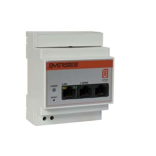
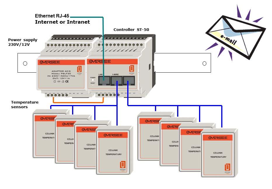
2 1. ST-50 Controller (Ethernet 1-Wire). To be able to operate, the ST-50 controller based monitoring system requires only a 12V power supply, connected directly to the controller and sensors or 1-Wire devices, as specified for individual solutions. Apart from standard sensors (for humidity, voltage and temperature measurements), integration modules are also available (for voltage measurements, with two counters and an optional switch) that make it possible to connect the bus with other devices equipped with an analog input, pulse input or two-state output. The ST-50 controller enables also control with any two-state switch, connected to the 1-Wire bus being monitored. NOTE: The recommended (optimal) connection topology for sensors is via a bus (serial topology). With such topology, you can extend the network of sensors across a distance of up to 100 m. 2. Technical requirements a) application To be able to launch the application, it is necessary to install the J2RE environment version 5.0 or higher, so that Java applications can run in the Graphics Mode. b) communication The ST-50 controller can be set up via Ethernet. For this, the following conditions need to be fulfilled: twisted-pair cable (crossover cable for direct connection with the computer s graphics card; straight cable for connections via a network switch/hub) one free IP address in your LAN, assigned permanently to the controller Optional: 1-Wire patch cord needed for connecting more 1-Wire devices When using a firewall, enable the following ports: Port 80 a Web panel for controller configuration Port 502 the controller s default communication port (can be changed during basic configuration of the controller) The maximum length of the 1-Wire bus must not exceed 150 m. 3. Basic configuration working parameters The Ethernet Operation Mode is set up with a website-based configuration tool, accessed via the controller. To display the website, enter the IP address assigned to the controller in your browser window, and then log in to your user account, defined in the controller. The default settings defined by the manufacturer are as follows: IP address: Login: zpas

3 Password: net Fig. 1. The controller login page. NOTE: To ensure better protection for the controller, change the default user name and password during the initial configuration.
4 The controller allows you to modify of the following connection parameters: ETHERNET: IP Address controller s IP address in LAN. This address is used for communication with the controller. It also provides access to the controller s configuration website. In the case of several controllers existing within the same subnet, each one has to have a unique IP address assigned to it. Mask the default subnet mask. In the case of LAN configuration, the mask parameters need not be modified. Gate the IP address of the gate. If you wish to access the controller from an external network (Internet), this address needs to correspond to the gate address, set for the subnet in which the controller is operated. MAC Address the hardware address of the controller s network module. Each controller has the same MAC address assigned to it. In the case of several controllers existing within the same LAN, each one should have a unique MAC address assigned to it. Otherwise, there is no need to modify it. MODBUS: Port Nb Modbus communication port. Via this port, the controller communicates with the configuration application. Device Address the internal Modbus address of the controller (Modbus slave address). It does not need to be modified, even when several controllers are installed within the same LAN. The address has been provided to ensure compatibility with the protocol. Modbus Password the password used for communication via Modbus. Confirm Password when attempting to modify the password, input the same string of characters both in Modbus Password and Confirm Password. PROTECTIONS: Login the name of a user authorized to configure the controller. Password the user password. The password must not be longer than 10 characters. Confirm Password when attempting to modify the password, input the same string of characters both in Modbus Password and Confirm Password. To save the settings, click Send. Having done that, you can still verify whether the data input is correct (the changes will be highlighted in red).

5 Fig. 2. The controller s operating parameter configuration page. When you click Send, the settings you have made will be stored in the memory, and the configuration page will be refreshed.
. 4.1.")
6 4. Controller configuration The controller can be configured using a Java-based application, capable of running in graphics environments of any operating system with Java Runtime Environment 5.0 or higher installed. This software is available free of charge, and the installer can be downloaded from the manufacturer s website ( Installation of the configuration application Once the application has been downloaded or having inserted the installation CD into the CD drive, launch the installer (st50-setup.exe) and follow the instructions it displays. The installation wizard will let you install the application together with the dedicated Java environment (Java Runtime Environment). If you do not have the JRE installed on your computer, select Zainstaluj środowisko Java (JRE 5.0) and follow the instructions displayed by the installation wizard. The default installation folder is C:\Program Files\ST-50 but it can be modified during installation. If the application has been installed successfully, a shortcut group should be created in the Start menu, similar to the one shown below: Fig. 3. A shortcut group in the Start menu. To launch the application, select the ST-50 configurator shortcut. NOTE: Should you have any problems with running the application, please refer to the Troubleshooting section or contact ZPAS-Net s Technical Support.

7 4.2. Program description Once the application has been launched, the main window will be displayed to give you access to all controller configuration options. Connect ith Disconne Add Alarm Delete Alarm Status Download Main application Alarm table header Edit Alarm Delete All Alarms Alarms tab Measurements tab Alarms table Fig. 4. The application window. To establish connection with the controller, click the Connect with... button or select the corresponding option form the Plik menu. In the window displayed (see point 4.2.3, Fig. 5), enter the connection details.
8 Menu options Plik Połącz z opens the connection window (see Fig. 5) Rozłącz closes the connection with the controller Zamknij closes the application Opcje Aliasy czujników opens the alias names window (see , Fig. 14.) Narzędzia Serwer opens the message server panel; it allows you to preview messages sent if the user selects the Send to server option when defining alarms (further details will be described later). Pomoc O programie displays information on the program
9 Buttons Connect with opens the connection window (see also Plik Połącz z ). Disconnect closes the connection (see also Plik Rozłącz ). Add Alarm opens the alarm definition window (Fig. 12). Once an alarm configuration has been saved, a new definition is added to the first empty slot in the controller s memory. Edit Alarm opens the alarm definition window (Fig. 12). It is possible to edit an alarm that has been highlighted in the alarms table. Saving the settings will overwrite the definition saved in the slot assigned to the alarm. Delete Alarm deletes the alarm highlighted in the alarms table. Before deletion, you will be asked to confirm your decision. Delete All Alarms deletes all alarms defined in the controller. Before deletion, you will be asked to confirm your decision. Alarm Status opens the alarm status window (Fig. 11). Download Data if connection with the controller has been established correctly, selecting this button will refresh all data downloaded from the controller. Depending on the number of alarms and/or sensors, this operation may take from several seconds to several minutes.


10 Dialog box Połącz z Fig. 6. The Connect with controller window. Adres urządzenia : IP address or domain name assigned to the controller. Adres urządzenia : since the controller uses the Modbus protocol, it is necessary to provide the slave address. The value input into the field must correspond to the value provided during the basic configuration made via the website. The default value is 1. Port: the network port used by the controller. This value must also correspond to the value provided during the basic configuration or, if the communication is established via a router or firewall, it is necessary to specify the port to which communication from/to the controller has been redirected. When you click the Połącz button, the application will attempt to establish connection with the controller. The default response time is 10 seconds. The connection status is displayed on the window title bar. During the next stage, all alarms and current measurement messages available in the controller are automatically downloaded. When the download process has been finished, a message will appear with the number of sensors and alarms that were downloaded from the controller. Fig. 8. The Data download finished window.

11 Alarmy (tab) The Alarmy tab contains a list of alarms defined in the controller. To refresh the values, click the Download Data button (see 4.2.2). Fig. 9. The Alarmy tab. The individual fields within the Alarmy tab: * alarm fault this field indicates the occurrence of a fault when checking the alarm status. The most common reason for this is disconnection of the 1-Wire sensor that was assigned with the alarm. If this is the case, the current value is always 0 with the alarm activity remaining the same as it was before the fault. The basic alarm codes are as follows: 0 status O.K Wire error (internal bus error) 200 unknown error 201 no device 202 internal error 203 wrong family code (incorrect MAC address of a sensor) ID (alarm ID) controller s memory slot number, under which the alarm has been stored. It is assigned automatically when creating a new alarm definition. MAC (sensor s MAC address) unique sensor number, specified by the manufacturer and preceded by a prefix common to the entire family. Nazwa (sensor s name) user-defined name of the measurement (see Aliasy czujników ). Bieżąca wartość (alarm current value) the current value downloaded from the sensor. The readout is updated according to an interval set for the given alarm. Hence, the value can differ from those for other alarms assigned to the same measurement.
12 Warunek available: (condition for the occurrence of an alarm) there are five conditions > the current value being higher than the condition value < the current value being lower than the condition value!= the current value being different than the condition value <= the current value being equal to or lower than the condition value >= the current value being equal to or higher than the condition value Wartość warunku the value being compared with the current value Akcja controller s response when the set condition is met. The field contains action symbols as follows: H (HTTP) a message is sent to a specified server. The option is enabled when fields in Serwer HTTP section are filled in correctly when defining the alarm (see Konfiguracja alarmu ). T (TEXT) the message being sent is accompanied by the user s own text, entered when defining the alarm. This feature is also enabled when the user has opted for notifications. M (MAC) the message being sent is accompanied by the sensor s MAC address. This option allows you to identify the location of the alarm. V (VALUE) the message being sent is accompanied by the status of the measurement that has caused the occurrence of the alarm. SA (SWITCH ACTIVE) occurrence of the alarm causes activation of the selected switch. SI (SWITCH INACTIVE) cancellation of the alarm causes activation of the selected switch. G[2] the alarm message is sent via . Value 2 next to the letter means that the message is sent both at occurrence and cancellation of the alarm.

.")
13 Pomiary (tab) The Pomiary tab shows information on all sensors that are currently connected to the ST-50 controller. In this window, you will find such values as: ID, type, MAC address, current measurement value, user-defined name. All these details help to identify measurements. Fig. 10. The Pomiary tab. Here you can also change the state of any switch within the 1-Wire bus being monitored. Status alarmu The alarm status window can be called up by highlighting any alarm from the available list, and then by clicking the Alarm Status button (see ). Fig. 11. The Status alarmu window. Clicking the Refresh button will re-download the current alarm parameters.
. Fig. 12.")
14 Konfiguracja alarmu The alarm configuration window is displayed by clicking the Add Alarm or Edit Alarm button (having highlighted the alarm to be edited on the list). Fig. 12. The alarm definition window.
15 Via the alarm configuration window, you can set the following: Czujnik using a drop-down list of all sensors, you can select one that will be assigned with the alarm being defined. Warunek alarm trigger condition options o Bieżąca wartość a read-only field that indicates the current measurement for the sensor highlighted on the list. o Warunek one of five available conditions (conditions listed in the description of the Alarmy tab). o Wartość warunku a value that if exceeded will cause the alarm to be triggered. o Histereza inertia of the measurement in relation to the defined condition value. It helps to prevent alarms from being triggered as the result fluctuates around the condition value. o Interwał [s] indicates how often is the alarm status to be refreshed. Ustaw stan przełącznika this option is available only when the bus contains switches (sensors with the SW_ prefix). When you check this property, you can select any switch together with its response to the alarm: o Ustaw, gdy alarm włączony alarm occurrence will activate the switch o Ustaw, gdy alarm wyłączony alarm cancellation will activate the switch Wyślij wiadomość this option allows you to send e- mails. o Wyślij wiadomość to be able to send an , you need to provide the correct address of the recipient. It is also possible to specify whether the is to be sent exclusively in response to the occurrence of an alarm or also in the case of its cancellation. Opcje wiadomości configuration of the content of messages being sent. o Dołącz tekst the message is accompanied by text that has been entered by the user into the text field below the option. A message can be up to 200 characters long. This length is further reduced when the Wyślij wiadomość option is checked. o Dołącz pomiar the message is accompanied by the measurement from the sensor assigned to the alarm. o Dołącz MAC czujnika the message contains the sensor s MAC address.
16 Once the selected alarm parameters have been defined, click the Zapisz button to store the alarm in the controller s memory in the first empty slot. The controller lets you store up to 40 freely configurable alarms. NOTE: Alarms can be assigned to most of available 1-Wire devices. The only exception here is the switch (sensor with the SW_ prefix) that can be controlled only by an alarm assigned to another sensor (the Ustaw stan przełącznika option).
 sensors together with their current values. Fig.")
17 Aliasy czujników To make it easier to identify 1-Wire sensors connected to the controller, it is possible to assign user-defined names (alias names). When you select Opcje Aliasy czujników, a window will be displayed containing a list of available (currently connected to the controller s 1-Wire bus) sensors together with their current values. Fig. 14. The alias name definition window. If you click the Zapisz button, values input in the Nazwa field will be automatically assigned to measurements. Leaving the Nazwa field blank will cause the MAC address of the measurement to be displayed. The list of all alias names is stored in an XML file named aliases.xml that is created in the installation folder.
18 5. Visualizing controller measurements In the case of individual installations for applications in households or small server rooms, you can use the FlashWizual software. The philosophy behind it is very simple. When you enter the controller address together with your login and password, you will be able to download sensor measurements and designations. All you need to do then is to arrange the images, animations and other visualization components to form visualization screens. With the Właściwości window, you can define component parameters and, if necessary, rescale the measurement data. A key advantage of the technology behind this software (Macromedia Flash) is the possibility of adding SWF animations to visualization screens. This includes also Action Script elements and advanced vector graphics. This all makes the tool a visually interesting working environment for supervising the monitored facilities. Once created, visualization screens can be saved and shared via a Web server using the ZPAS Control Oversee system. In such case, you gain access to additional remote tools for viewing measurement archives, using aggregation functions and handling alarms. Below, you will see a working environment for creating visualization screens. The window shows components and their properties. For convenience, whenever possible, visualizations can be created by dragging and dropping components with a mouse.
19 Fig. 16. A sample visualization of controller measurements.
20 5.1. First steps with FlashWizual FlashWizual will display all measurements that have been assigned with alarms in the controller s configuration software. The remaining measurements will not be visible. After successful configuration, the next step is to read the available variables from the controller. To do so, go to Połączenia Sterownik. Once connection with the controller has been established, information on measurements should be available: For subsequent operations, you can use names of measurement available in the controller. For example, if you want to display the measurement of temperature, position the Opis component from the library over the visualization screen and set the corresponding measurement of temperature in the menu. To facilitate identification, the ID of the sensor is preceded by the T_ prefix. For convenience, the measurement value is accompanied by text input in the Opis field, for instance to indicate the unit of measurement, e.g. C, % and more. For unconverted measurements, e.g. humidity, it may be necessary to convert them before they are displayed. This can be done by using conversion factors A, B and Offset. The result is then displayed according to the following formula: X = (Measurement * A)/B + Offset For humidity, A=32.6, B=1, Offset= -25.8
21 Displaying temperature measurements: Displaying humidity measurements:
22 Measurements can also be used to control component parameters. The examples include displaying an image in response to the occurrence of the flooding alarm. The flooding sensor at the integration module is triggered by the ground signal. In the absence of flooding, the controller s measurement is at 5V, whereas during flooding, it drops to below 4.5V. Therefore, A needs to be set to -1, and Offset to 5. Here is an example: Another possible application for measurements are macros. Start defining macros by providing a name and then selecting a macro in the Zarządzanie makrami window: For instance, the following conditional statement:
23 IF [V_FB DFFA26]>1 then CHPAR(Progress_bar3,_visible,false); will have the following effect: when the measurement value is greater than 1, the _visible parameter of the Progress_bar3 component will change to false. If you want the conditional statement to be executed for each measurement, make sure it is included in the onpomiar macro. A macro can also be activated by clicking a button or an image. However, such macro needs to be assigned to the component. To do so, select it from the properties window.
24 Macros support the following commands: Command name CHPAR Action, example Changing parameters for components in use. CHPAR(Component_name,attribute,value) CHPAR(Image1,x,100) ATTRIBUTES: text alpha visible x y height width xscale yscale colour IF Conditional statement IF T1=0 then CHPAR(Image1,_visible,true) PRINT_FORM Printing the displayed visualization. RUN Running another visualization screen. RUN( run5.ovr )
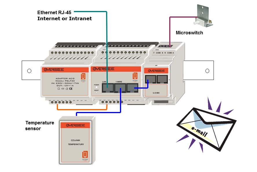
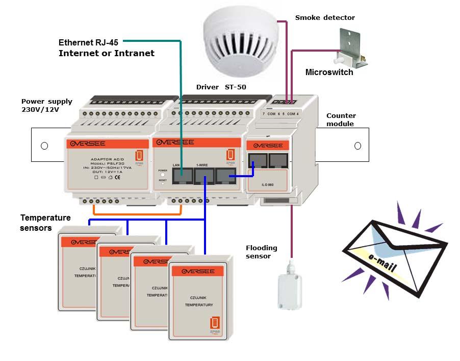
25 6. Sample connection diagrams
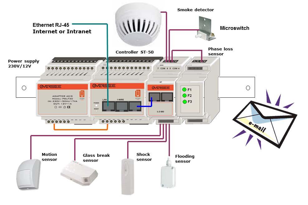
26
27 7. Troubleshooting and FAQs JAVA environment 1. How to check the current version of the JRE? MS Windows: Go to Start Run and launch the cmd command. Enter the following string in the displayed window: java version Unix/Linux: Enter the following string in the system console: java -version 2. Error: javaw is not recognized as a command This error occurs when no JAVA environment is installed or its paths are incorrect. To solve the problem, add the destination folder of the javaw.exe file to the PATH variable (by default: C:\Program Files\Java\jre1.5.0_11\bin). 3. Error: Exception in thread "main" java.lang.noclassdeffounderror: org/jdom/content The package needed to be able to launch the application has not been found. The application needs to be reinstalled. 4. The program cannot be launched. Please reinstall the application. Defining alarms 1. How many alarms can be defined in the controller? The ST-50 controller can store up to 24 alarm conditions. 2. How can I simultaneously send an alarm notification to a phone number and address? You need to define two similar alarms that differ only in the notification method. 3. The controller cannot send messages. The reasons can be numerous: an incorrect address has been entered an incorrect SMTP server has been entered
28 8. Contact information Technical Support and IT Development Department Phone 0 (10xx) 74 / www: Zakład Produkcji Automatyki Sieciowej S.A. ul. Przygórze Wolibórz
ION Meter Alerts TECHNICAL NOTE NOVEMBER In This Document
 70072-0125-01 TECHNICAL NOTE NOVEMBER 2006 ION Meter Alerts A PowerLogic ION meter can send alerts to indicate a user specified power system condition such as a power quality problem (including surges,
Avigilon Control Center 5 System Integration Guide
 Avigilon Control Center 5 System Integration Guide for Paxton Net2 Access Control Systems 2014 Avigilon Corporation. All rights reserved. Unless expressly granted in writing, no license is granted with
Alarm Client. Installation and User Guide. NEC NEC Corporation. May 2009 NDA-30364, Revision 9
 Alarm Client Installation and User Guide NEC NEC Corporation May 2009 NDA-30364, Revision 9 Liability Disclaimer NEC Corporation reserves the right to change the specifications, functions, or features,
Smart Combiners Installation Guide. For Obvius A89DC-08 sensor modules
 For Obvius A89DC-08 sensor modules Introduction Large roof and ground arrays connect the panels into stings that are merged together in combiner boxes. Each string will typically consist of 10-15 panels
Avigilon Control Center System Integration Guide
 Avigilon Control Center System Integration Guide with Velocity INT-HIRSCH-A-Rev3 Copyright 2013 Avigilon. All rights reserved. No copying, distribution, publication, modification, or incorporation of this
Ion Gateway Cellular Gateway and Wireless Sensors
 Page 1 of 9 Account & Network Setup If this is your first time using the Ion Gateway online system site you will need to create a new account. If you have already created an account you can skip to the
Milestone SMI Intrepid II Perimeter Module 1.1 User s Manual
 Milestone SMI Intrepid II Perimeter Module 1.1 User s Manual Target Audience for this Document This document is aimed at system users and provides descriptions on how to install and maintain the Milestone
Setting up and Managing Alarms in McAfee ESM 10.x
 McAfee SIEM Alarms Setting up and Managing Alarms in McAfee ESM 10.x Introduction McAfee SIEM provides the ability to send alarms on a multitude of conditions. These alarms allow for users to be notified
PWM. Solar Charge controller with Ethernet. Solar Smart PWM 20Amp. Hardware Description : Release : 19 June 2014
 Solar Charge controller with Ethernet Release : 19 June 2014 Hardware Version : Version 1 Firmware version 1 PC Application Software : Version 1.0.0.0 Hardware Description : The Solar Smart regulator was
ibox Modbus Server Gateway for the integration of Notifier ID3000 / ID3002 / ID60 / ID50 fire panels in Modbus enabled monitoring and control systems
 Honeywell Life Safety Iberia C/Pau Vila 15-19; 08911 Badalona Barcelona T. 902 03 05 45; Internacional:+34932424236 www.honeywelllifesafety.es infohlsiberia@honeywell.com ibox Modbus Server Gateway for
MultiSite Manager. Setup Guide
 MultiSite Manager Setup Guide Contents 1. Introduction... 2 How MultiSite Manager works... 2 How MultiSite Manager is implemented... 2 2. MultiSite Manager requirements... 3 Operating System requirements...
IndigoVision Alarm Panel. User Guide
 IndigoVision Alarm Panel User Guide THIS MANUAL WAS CREATED ON 2/21/2017. DOCUMENT ID: IU-AP-MAN002-4 Legal considerations LAWS THAT CAN VARY FROM COUNTRY TO COUNTRY MAY PROHIBIT CAMERA SURVEILLANCE. PLEASE
Table of Contents. i-vu CCN Standard 4.2
 i-vu CCN Standard 4.2 Owner's Guide CARRIER CORPORATION 2009 A member of the United Technologies Corporation family Stock symbol UTX Catalog No. 11-808-381-01 7/13/2009 Table of Contents Accessing your
PAPERLESS RECORDER COMMUNICATION FUNCTION (Ethernet)
") Instruction Manual PAPERLESS RECORDER COMMUNICATION FUNCTION (Ethernet) TYPE: PHU INP-TN5A0024-E Note: MODBUS is the registered trade mark of AEG Schneider Aumaion International. NOTICE 1. Exemption items
Instruction Manual PAPERLESS RECORDER COMMUNICATION FUNCTION (Ethernet) TYPE: PHU INP-TN5A0024-E Note: MODBUS is the registered trade mark of AEG Schneider Aumaion International. NOTICE 1. Exemption items
Avigilon System Integration Guide. for the Avigilon Control Center and Access Control Manager
 Avigilon System Integration Guide for the Avigilon Control Center and Access Control Manager 2014-2017, Avigilon Corporation. All rights reserved. AVIGILON, the AVIGILON logo, ACC, AVIGILON CONTROL CENTER,
Avigilon Control Center System Integration Guide
 Avigilon Control Center System Integration Guide with Gallagher Command Centre INT-CARDAX-C-Rev3 Copyright 2013 Avigilon. All rights reserved. No copying, distribution, publication, modification, or incorporation
Metasys System Extended Architecture Fire System Integration Using the IFC BACnet Gateway
 Metasys System Extended Architecture Fire System Integration Using the IFC BACnet Gateway Code No. LIT-1201993 Software Release 2.1 Issued April 12, 2006 Supersedes July 20, 2005 Document Introduction.................................................
Avigilon System Integration Guide. for the Avigilon Control Center and Access Control Manager
 Avigilon System Integration Guide for the Avigilon Control Center and Access Control Manager 2014-2016, Avigilon Corporation. All rights reserved. AVIGILON, the AVIGILON logo, AVIGILON CONTROL CENTER,
i-vu CCN 4.0 Owner s Guide
 i-vu CCN 4.0 Owner s Guide CARRIER CORPORAION 2007 A member of the United echnologies Corporation family. Stock symbol UX. 11-808-377-01 07/07 able of Contents ACCESSING YOUR SYSEM... 3 YOUR SYSEM DEAILS...
HERCULES 6 GRAPHICS SYSTEM
 HERCULES 6 GRAPHICS SYSTEM USER MANUAL Protec Fire Detection PLC, Protec House, Churchill Way, Nelson, Lancashire, BB9 6RT. Telephone: +44 (0) 1282 717171 Fax: +44 (0) 1282 717273 Web: www.protec.co.uk
CSP-204 CSP-208 CSP-104 CSP-108
 Fire Alarm Control Panel CSP-204 CSP-208 CSP-104 CSP-108 Operation manual Firmware version 1.1 csp-x_o_en 06/15 SATEL sp. z o.o. ul. Budowlanych 66 80-298 Gdańsk POLAND tel. 58 320 94 00 www.satel.eu CONTENTS
Bosch TCU Integration Module Administrator's Guide
 Bosch TCU Integration Module 1.0 - Administrator's Guide 10 Dec 2008 Rev 1.2 Table of Contents 1 Overview... 3 1.1 Compatibility...3 1.2 References...3 2 Installation... 4 3 Configuration... 5 3.1 System
Avigilon Control Center System Integration Guide
 Avigilon Control Center System Integration Guide with Gallagher Command Centre INT-CARDAX-C-Rev2 Copyright 2011 Avigilon. All rights reserved. No copying, distribution, publication, modification, or incorporation
Simplex Panel Interface Guide
 Simplex Panel Interface Guide February 2016 SATEON Software Integrations Simplex Panel Interface Guide Issue 1.0, released February 2016 Disclaimer Copyright 2016, Grosvenor Technology. All rights reserved.
Added password for IP setup page : Password must be in IP format!
 NETWORK POWER MONITOR Release : 21 August 2014 Hardware Version : Version 7 Firmware version 1.00 PC Application Software : Version (latest)...2 Added password for IP setup page : Password must be in IP
RMS Monitoring Software System Startup
 System Startup 2017 ROTRONIC AG Bassersdorf Switzerland 2017 ROTRONIC AG Bassersdorf Switzerland Page 2 of 53 Contents Contents... 3 1 Overview... 5 1.1 System Requirements... 5 1.1.1 Browser... 5 2 Create
Installation, Configuration and User Manual
 Model 8826 System Controller Model 8826 System Controller Installation, Configuration and User Manual READ AND SAVE THESE INSTRUCTIONS WELCOME Thank you for choosing the Aprilaire HVAC Automation System.
AK-CS On Board Guide
 MAKING MODERN LIVING POSSIBLE AK-CS On Board Guide electronic controls & sensors About this guide The AK-CS On Board guide highlights the use of the RMT tool, allowing remote software management. Consult
Alarm Monitoring and Management
 CHAPTER 10 This chapter describes Cisco Transport Controller (CTC) alarm management. To troubleshoot specific alarms, refer to the Cisco ONS 15310-MA SDH Troubleshooting Guide. Chapter topics include:
Installation Manual. ATS Remote Annunciator Catalog 5350 DANGER WARNING D
 ASCO 5350 The ASCO 5350 ATS Remote Annunciator is listed under the Underwriter s Laboratories Standard UL-1008 for Automatic Transfer Switch accessories. This stand-alone device provides individual status
Installing ProSeries 2005
 Installing ProSeries 2005 The following instructions will walk you through Installing and Launching ProSeries 2005. Before you begin your installation, it is very important to make note of the following
Halton SAFE / 7.14 user guide and installation instructions
 Halton SAFE / 7.14 user guide and installation instructions VERIFIED SOLUTIONS BY H A LTO N Enabling Wellbeing Table of contents 1 System description 3 2 User Accounts 4 3 Main menu 7 3.1 Main menu - Change
Avigilon Control Center 5 System Integration Guide
 Avigilon Control Center 5 System Integration Guide with Hirsch Velocity INT-HIRSCH-B-Rev1 2012 2014 Avigilon Corporation. All rights reserved. Unless expressly granted in writing, no license is granted
Diagnostics and Monitoring System WEB Tool 2. User Manual
 Diagnostics and Monitoring System 2 (Translation of the original documentation) User Manual S/N: Valid from: 01.05.2012 Rev.: 2.0 2 Rev. 1.... 1 1.1 General information... 1 1.1.1 Equipment... 1 1.1.2
USER MANUAL DexTempTM 1000 Temperature Monitor (P/N: IR-1001) DexTempTM 1000 USB Non-Contact Temperature Monitor. User Manual.
 DexTempTM 1000 USB Non-Contact Temperature Monitor. User Manual.") USER MANUAL DexTempTM 1000 Temperature Monitor (P/N: IR-1001) DexTempTM 1000 USB Non-Contact Temperature Monitor User Manual 8690 Rev B Update: 10/24/2013 1 Table of Contents 1 Introduction.. 3 2 Host
USER MANUAL DexTempTM 1000 Temperature Monitor (P/N: IR-1001) DexTempTM 1000 USB Non-Contact Temperature Monitor User Manual 8690 Rev B Update: 10/24/2013 1 Table of Contents 1 Introduction.. 3 2 Host
OnGuard 7.1 Resolved Issues
 Lenel Systems International, Inc. 1212 Pittsford-Victor Road Pittsford, New York 14534 Tel 866.788.5095 Fax 585.248.9185 www.lenel.com Contents OnGuard 7.1 Resolved Issues 1. Introduction... 2 2. Access
ArchestrA Direct Connect
 Table of Contents ArchestrA Direct Connect... 1 Introduction... 1 ArchestrA Direct Connection... 1 ArchestrA Data Source Definition... 2 Data Source Definition... 2 Importing Alarms from ArchestrA... 6
Yokogawa DX Ethernet Driver Help Kepware Technologies
 Yokogawa DX Ethernet Driver Help 2012 Kepware Technologies 2 Table of Contents Table of Contents 2 4 Overview 4 Device Setup 5 Communications Parameters 7 Optimizing Your Ethernet Communications 9 Data
Manage Alarms. Before You Begin CHAPTER
 CHAPTER 9 Manage Alarms This chapter contains the procedures for viewing and managing the alarms and conditions on a Cisco ONS 15454 SDH. Cisco Transport Controller (CTC) detects and reports SDH alarms
Trident User s Manual
 Labkotec Oy Myllyhaantie 6 33960 Pirkkala FINLAND Tel. +358 (0)29 006 260 18.05.2017 Fax +358 (0)29 006 1260 Internet: www.labkotec.fi 34 pages Trident Copyright 2017 Labkotec Oy 1/34 TABLE OF CONTENTS
FortiNAC. Lightspeed Single Sign-On Integration. Version: 8.x Date: 8/29/2018. Rev: B
 FortiNAC Lightspeed Single Sign-On Integration Version: 8.x Date: 8/29/2018 Rev: B FORTINET DOCUMENT LIBRARY http://docs.fortinet.com FORTINET VIDEO GUIDE http://video.fortinet.com FORTINET KNOWLEDGE BASE
RADview-EMS/TDM. Element Management System for TDM Applications Optimux RAD Data Communications Publication 07/04
 RADview-EMS/TDM Element Management System for TDM Applications Optimux-1553 1994 2004 RAD Data Communications Publication 07/04 Contents Chapter 1. Introduction 1.1 Overview... 1-1 1.2 System Features...
Integration with Mobotix Q24
 Integration with Mobotix Q24 Camera This is the third tutorial from the series of tutorials describing integration of the DOMIQ system with Mobotix devices. In the previous tutorials we described the integration
Alarm User Guide IGSS Version 9.0
 Alarm User Guide IGSS Version 9.0 Table of Contents Chapter 1: The Alarm List 4 1.1 Introducing the Alarm List 4 Process alarms and 'IGSS Alarm' 4 How is an alarm identified? 4 Alarm characteristics 4
IndigoVision. GAI-Tronics Integration Module. Administrator's Guide
 IndigoVision GAI-Tronics Integration Module Administrator's Guide GAI-Tronics Integration Module THIS MANUAL WAS CREATED ON 10 APRIL 2013. DOCUMENT ID: IU-IM-MAN019-1 Legal Considerations LAWS THAT CAN
Niagara4 Technical Certification Program Student Guide DAY 1 DAY 2
 Niagara4 Technical Certification Program Student Guide DAY 1 Welcome Course Introduction Platforms & Stations Niagara4 Fundamentals Simple Logic: Hot Water Pump Control (Thermostatic) Simple Logic: Hot
Universal Monitoring System. Model IMEC8A. User Manual Version 1.10 Software version 2.3.1
 Unit 7/8, Heathrow Causeway Estate, Ariel Way, Hounslow Middlesex, TW4 6JW +44 (0) 208 6302270 www.cpcuk.co.uk Universal Monitoring System Model IMEC8A User Manual Version 1.10 Software version 2.3.1-1
Apertum. Working with the Alarm Module. How to define and configure alarms How to visualize and recognize alarms. Airviro User s Reference.
 Apertum Volume 8 Airviro User s Reference Working with the Alarm Module How to define and configure alarms How to visualize and recognize alarms Working with Alarm Module - How to define and configure
Before you install ProSeries Express Edition software for network use
 Before you install ProSeries Express Edition software for network use The following pages describe system requirements and other information you need to know before installing ProSeries Express Edition
AK SM 800 Commissioning Guide
 AK SM 800 Commissioning Guide AK-SM 800 step-by-step ADAP-KOOL Oy Danfoss Ab / Kylmäosasto 1 Intro... 3 Connection to the system... 5 Software version... 7 Preferences wizard... 8 Users wizard... 10 Alarm
Using ANM Mobile CHAPTER
 CHAPTER 19 Date: 3/22/13 This chapter describes Cisco ANM Mobile, which allows you to access your ANM server or ANM Virtual Appliance and manage your devices using a mobile device such as an iphone or
Alarm Monitoring and Management
 14 CHAPTER This chapter explains how to manage alarms with Cisco Transport Controller (CTC). To troubleshoot specific alarms, refer to the Cisco ONS 15454 SDH Troubleshooting Guide. Chapter topics include:
Model 135 Reference Document
 Model 135 Reference Document 2007 by Gordon Kapes, Inc. all rights reserved 5520 West Touhy Avenue Skokie, Illinois 60077 USA Telephone 847 676-1750 Fax 847 982-0747 www.gkinc.com 40218, Issue 1 January
Tech Data Sheet D01662GB0_Esgraf 4.1 and Configuration Server 30/2011 2/(5)
") Tech Data Sheet D01662GB1_Esgraf 4.1 and Configuration Server 30/2011 1/(5) Esgraf 4.1 graphical user interface, configuration server and fire detectors contamination monitoring Esgraf 4.1 ESGRAF is a
Tech Data Sheet D01662GB1_Esgraf 4.1 and Configuration Server 30/2011 1/(5) Esgraf 4.1 graphical user interface, configuration server and fire detectors contamination monitoring Esgraf 4.1 ESGRAF is a
Avigilon Control Center 5 System Integration Guide. with STENTOFON AlphaCom. INT-STENTOFON-C-Rev1
 Avigilon Control Center 5 System Integration Guide with STENTOFON AlphaCom INT-STENTOFON-C-Rev1 2013 2014 Avigilon Corporation. All rights reserved. Unless expressly granted in writing, no license is granted
ModSync Sequencing System Installation & Operation Manual. For use with Fulton Steam Boilers.
 ModSync Sequencing System Installation & Operation Manual For use with Fulton Steam Boilers. Revision 3.0 8/21/2008 - 2 - Table of Contents Introduction Page 4 Features Page 4 Sequence of Operation Page
HikCentral Web Client. User Manual
 HikCentral Web Client User Manual Legal Information User Manual 2018 Hangzhou Hikvision Digital Technology Co., Ltd. About this Manual This Manual is subject to domestic and international copyright protection.
AUTOMATION. Operator s Manual RST Series Web Enabled Input Module. Rev. A2, 1/12
 AUTOMATION P R O D U C T S GROUP, INC. Operator s Manual RST-5000 Series Web Enabled Input Module Rev. A2, 1/12 Tel: 1/888/525-7300 Fax: 1/435/753-7490 www.apgsensors.com E-mail: sales@apgsensors.com RST-5000
ICT180S-12I INTELLIGENT MODEL (SERIES 2)
") The Power of Reliability ICT180S-12I INTELLIGENT MODEL (SERIES 2) INSTRUCTION MANUAL TABLE OF CONTENTS Warnings Page 2 Product Description Page 3 Installation Page 4 LCD/Select Button Operation Page 7
The Power of Reliability ICT180S-12I INTELLIGENT MODEL (SERIES 2) INSTRUCTION MANUAL TABLE OF CONTENTS Warnings Page 2 Product Description Page 3 Installation Page 4 LCD/Select Button Operation Page 7
Operation Manual Fighter ProVision Software. Version: 0.0 Revision: 1
 Operation Manual Fighter ProVision Software Version: 0.0 Revision: 1 TABLE OF CONTENTS 1. Introduction 5 2. Software Installation 5 3. PC Users 6 3.1 Introduction 6 3.2 Default Code 6 3.3 Edit PC User
Managing Network Alarms and Events
 9 CHAPTER Prime Performance Manager allows you to view alarms and events that occur in your network. The following topics provide information about displaying network alarms and events: Displaying Active
Paradox Integration Module Settings Guide
 Paradox Integration Module Settings Guide List of Terms used in Paradox Integration Module Settings Guide............. 3 Introduction into Paradox Integration Module Settings Guide............... 4 Configuration
Alarm System Example
 Alarm System Example ASD:Suite Copyright 2013 Verum Software Technologies B.V. ASD is licensed under EU Patent 1749264, Hong Kong Patent HK1104100 and US Patent 8370798 All rights are reserved. No part
Manage Alarms. Before You Begin CHAPTER
 CHAPTER 8 Manage Alarms This chapter contains the procedures for viewing and managing the alarms and conditions on a Cisco ONS 15454. Cisco Transport Controller (CTC) detects and reports alarms generated
Avigilon System Integration Guide. Avigilon Control Center with AMAG Symmetry Security Management System 7.0
 Avigilon System Integration Guide Avigilon Control Center with AMAG Symmetry Security Management System 7.0 2013-2016, Avigilon Corporation. All rights reserved. AVIGILON, the AVIGILON logo, HDSM, HIGH
Alarm module for leak detection with webserver
 This instruction document consists of 2 parts : one part about the assembly of the components and one part about configuration and starting-up of the system. The assembly is done by the qualified installer
Security Management System Configuring TCP-IP MODBUS Inputs
 Security Management System Configuring TCP-IP MODBUS Inputs This document explains the configuration of TCP/IP MODBUS devices in the Security Management System Server software. A) Configuring TCP-IP MODBUS
Instruction manual MTL process alarm equipment. October 2016 CSM 725B rev 2 MTL RTK 725B. Configuration Software Manual
 Instruction manual MTL process alarm equipment October 2016 CSM 725B rev 2 MTL RTK 725B Configuration Software Manual SECTION 1 - INTRODUCTION... 5 Basic Requirements... 5 SECTION 2 - SOFTWARE INSTALLATION...
Med Touch Master Alarm
 Submittal Data Sheet Features The Powerex Med Touch Master Alarm Panel monitors and displays normal and alarm conditions from up to 128 remote medical gas source signals and provides alarm conditions as
ESB Tools Reference Guide. Version: CR2
 ESB Tools Reference Guide Version: 1.1.0.CR2 1. Introduction... 1 1.1. What is ESB?... 1 1.2. Other relevant resources on the topic... 1 2. ESB Support... 3 2.1. ESB Tools Installation... 3 2.2. Creating
ESB Tools Reference Guide. Version: GA
 ESB Tools Reference Guide Version: 1.1.0.GA 1. Introduction... 1 1.1. What is ESB?... 1 1.2. Other relevant resources on the topic... 1 2. ESB Support... 3 2.1. ESB Tools Installation... 3 2.2. Creating
Proliphix. NT10e & NT20e. Configuration Guide
 Proliphix NT10e & NT20e Configuration Guide Rev 2.5 Page i of iii TABLE OF CONTENTS INTRODUCTION...5 THERMOSTAT MANAGEMENT INTERFACE (TMI) AUTHENTICATION...5 QUICK SETUP...5 IP Addressability...5 Real
Monitor Alarms and Events
 This chapter contains the following topics: What Are Alarms and Events?, page 1 How are Alarms and Events Created and Updated?, page 2 Find and View Alarms, page 3 Set Alarm and Event Management Preferences,
Lighting Xpert Insight User Manual
 Lighting Xpert Insight User Manual Table of Contents 1 About This Document... 3 1.1 Key Terms... 3 1.2 Related Fifth Light Documentation... 3 2 Lighting Xpert Insight Overview... 4 2.1 Key Features...
Alarm Coordination Connected Components Building Block. Quick Start
 Alarm Coordination Connected Components Building Block Quick Start Important User Information Solid state equipment has operational characteristics differing from those of electromechanical equipment.
HikCentral Web Client. User Manual
 HikCentral Web Client User Manual Legal Information User Manual 2018 Hangzhou Hikvision Digital Technology Co., Ltd. About this Manual This Manual is subject to domestic and international copyright protection.
Monitor Alarms and Events
 What Are Alarms and Events?, page 1 How are Alarms and Events Created and Updated?, page 2 Which Events Are Supported?, page 5 Set Alarm and Event Management Preferences, page 5 Interpret Event and Alarm
Raytec Avigilon Integration User Guide Integrating Raytec Network Illuminators with Avigilon Control Center Document Revision 2.0
 Raytec Avigilon Integration User Guide Integrating Raytec Network Illuminators with Avigilon Control Center Document Revision 2.0 Table of Contents 1 INTRODUCTION... 3 1.1 OVERVIEW... 3 1.2 SOFTWARE COMPONENTS...
D-TECT 3 IP. GJD260 IP Motion Detector
 D-TECT 3 IP GJD260 IP Motion Detector PACKAGE CONTENTS 1 x D-TECT 3 IP 1 x Drilling template for fixing holes 3 x 31.75mm wall plugs 3 x 31.75mm screws 2 x Spare sliding curtains 2 x Tamper feet 1 x Tamper
Ambient Temperature/ Relative Humidity & Dew Point Temperature Sensors to USB Output. Model LFS108B
 Ambient Temperature/ Relative Humidity & Dew Point Temperature Sensors to USB Output Model LFS108B Copyright 2018 - LLC. All rights reserved. Table of Contents Quick Start... 3 1- Introduction... 4 2-
Please use authentic SATA hard drive, USB device and battery.
 Note The device should be set in the room with good ventilation, far from water, hot reservoir or dust. Network Video Recorder is not designed to be used outdoor. Please use authentic SATA hard drive,
CompleteView Alarm Client User Manual. CompleteView Version 4.6.1
 CompleteView Alarm Client User Manual CompleteView Version 4.6.1 Table of Contents Introduction... 1 Overview...2 System Requirements...2 Configuration... 3 Starting the Alarm Client...3 Menus...3 File
Running IGSS as an Operator, Part One
 Running IGSS as an Operator, Part One Contents Duration We want to see how a completed IGSS SCADA system appears to plant operator personnel to get an idea of the various elements in the system and how
CRIME. Manufacturing And Minor Inventions CRIME. Control Room Integrated Monitoring Environment
 Control Room Integrated Monitoring Environment INDEX 1. Requirements for software. 2. Installation Instructions. 3. How to Register your Software. 4. Start Using... 5. Operating Instructions. 6. Screen
Monitoring Operator Guide. Access Control Manager Software Version
 Monitoring Operator Guide Access Control Manager Software Version 5.10.10 2018, Avigilon Corporation. All rights reserved. AVIGILON, the AVIGILON logo, ACCESS CONTROL MANAGER, ACM, ACM VERIFY AND TRUSTED
Centroid Snet 2. Battery Management Software. User Manual V1.1. Eagle Eye Power Solutions, LLC Keeping an Eye on Your Critical Power!
 Eagle Eye Power Solutions, LLC Keeping an Eye on Your Critical Power! Centroid Snet 2 Battery Management Software User Manual V1.1 www.eepowersolutions.com Tel: 1-877-805-3377 info@eepowersolutions.com
Avigilon Control Center System Integration Guide
 Avigilon Control Center System Integration Guide with Picture Perfect 4 INT-PP4-A-Rev1 Copyright 2012 Avigilon. All rights reserved. No copying, distribution, publication, modification, or incorporation
Tri-Tech Medical Inc.
 Submittal Data Sheet Project Information Project Number Approval Features The Master Alarm Panel conversion kits are designed to upgrade or retro-fit existing panels produced by several major brands. The
D-TECT 2 IP. GJD230 IP Motion Detector
 D-TECT 2 IP GJD230 IP Motion Detector PACKAGE CONTENTS 1 x D-TECT 2 IP 1 x Drilling template for fixing holes 3 x 31.75mm wall plugs 3 x 31.75mm screws 2 x Spare sliding curtains 2 x Tamper feet 1 x Tamper
Laptop / PC Programming Manual
 Laptop / PC Programming Manual Doc. # Fire PC Program rev B 01.07 This Document is property of Evax Systems, Inc. The Evax Fire Solutions Programmer Components 2 1.0 System Setup 4 1.1 Interface Setup
Security Escort Central Console Software SE2000 Series
 Release Notes Security Escort Central Console Software SE2000 Series Table of Contents 1 Security Escort v2.18.1.0... 2 1.1 Enhancements... 2 1.2 Errors Fixed... 2 1.3 Known Limitations and Restrictions...
Patriot Systems Limited
 COPYRIGHT 1997 - The Patriot Systems Ltd. Patriot Alarm Monitoring Automation Package is licensed for use on one computer, by the original person, or company, or organization whose name is registered with
Installing ProSeries 2004
 Installing ProSeries 2004 The following instructions will walk you through Installing and Launching ProSeries 2004. Before you begin your installation, it is very important to make note of the following
BlackBerry AtHoc Networked Crisis Communication Siemens Indoor Fire Panel Installation and Configuration Guide Release Version 7.
 BlackBerry AtHoc Networked Crisis Communication Siemens Indoor Fire Panel Installation and Configuration Guide Release Version 7.3, October 2017 Copyright 2017 BlackBerry Limited. All Rights Reserved.
WiFi Hints & Tips. Contents. WiFi Hints and Tips 1. Page No. Section No. Title
 WiFi Hints & Tips Contents Page No. Section No. Title Section.0 System Set-Up 3 Section. Sensor Set-Up 4-5 Section. Sensor Set-Up (Configuring Network) 6-9 Section.3 Sensor Set-Up (Configuring Settings)
ENTOUCH ONE USER GUIDE
 ENTOUCH ONE USER GUIDE v4.0 MEASURE. MANAGE. SAVE. Contents Getting Started 3 Installation 7 Using the Setup Wizard 11 Using the Home Screen 12 Using the Main Menu 16 The Setup Menu 19 Using the Web Management
Procidia iware AlarmWorX32. AlarmWorX32 Viewer January 2010
 Procidia iware AlarmWorX32 AlarmWorX32 Viewer Siemens Protection AG 2008. notice All / Copyright rights reserved. notice Introduction / Contents Procidia iware is an operator interface software designed
Proliphix. Remote Management. User Guide
 Proliphix Remote Management User Guide Rev 2.5 Page 2 of 12 Table of Contents Intended Audience...3 Remote Management...4 Remote Management Interface (RMI)...5 Accessing My Account... 5 Device List Page...
BROADBAND MODEL WITH REMOTE POWER CONTROL (SERIES 2) ICT180S-12BRC (FOR POSITIVE GROUND SYSTEMS) ICT180S-12BRCP (FOR NEGATIVE GROUND SYSTEMS)
 ICT180S-12BRC (FOR POSITIVE GROUND SYSTEMS) ICT180S-12BRCP (FOR NEGATIVE GROUND SYSTEMS)") The Power of Reliability BROADBAND MODEL WITH REMOTE POWER CONTROL (SERIES 2) ICT180S-12BRC (FOR POSITIVE GROUND SYSTEMS) ICT180S-12BRCP (FOR NEGATIVE GROUND SYSTEMS) INSTRUCTION MANUAL TABLE OF CONTENTS
The Power of Reliability BROADBAND MODEL WITH REMOTE POWER CONTROL (SERIES 2) ICT180S-12BRC (FOR POSITIVE GROUND SYSTEMS) ICT180S-12BRCP (FOR NEGATIVE GROUND SYSTEMS) INSTRUCTION MANUAL TABLE OF CONTENTS
Operations Manual TS400. Test Station for G450/G460 Gas Detector
 TS400 Test Station for G450/G460 Gas Detector Operations Manual 1194 Oak Valley Dr, Ste 20, Ann Arbor MI 48108 USA (800) 959-0329 (734) 769-0573 www.goodforgas.com GfG Products for Increased Safety Congratulations