Release 4. System Description. AutroSafe Interactive Fire Detection System. 116-P-ASAFE-SYSTEMD/EGB Rev. H, , Autronica Fire And Security AS
|
|
|
- Griffin Barber
- 5 years ago
- Views:
Transcription


1 p Release 4 System Description AutroSafe Interactive Fire Detection System 116-P-ASAFE-SYSTEMD/EGB Rev. H, Autronica Fire And Security AS
2 COPYRIGHT This publication, or parts thereof, may not be reproduced in any form, by any method, for any purpose. and its subsidiaries assume no responsibility for any errors that may appear in the publication, or for damages arising from the information in it. No information in this publication should be regarded as a warranty made by. The information in this publication may be updated without notice. Product names mentioned in this publication may be trademarks. They are used only for identification. E-1676 This product contains static-sensitive devices. Avoid any electrostatic discharge. The WEEE Directive When the marking below is shown on the product and/or its literature, it means that the product should not be disposed with other household wastes at the end of its life cycle. During waste treatment, disposal and collection, please separate the product from other types of wastes and recycle it responsibly to promote the sustainable reuse of material resources. This product should not be mixed with other commercial wastes for disposal. System Description, AutroSafe Interactive Fire Detection System, 116-P-ASAFE-SYSTEMD/EGB Rev. H, Autronica Fire and Security
3 Introduction
4 Introduction Table of Contents 1. Introduction About the Handbook The Reader Reference Documentation Compliance to Standards Compliance with Regulations and Standards EN 54-2 Functionality List Optional functions with requirements of this European Standard Functions relating to other parts of EN Ancillary functions not required by this European Standard CE Marking Information Terms, Abbreviations/Acronyms and Definitions System Characteristics Introduction Cyber Security Safety Functions Onshore Market / Maritime Market Petrochemical, Oil & Gas Market Maritime Gas Installation AutroNet - the Local Area Network AutroFieldBus the Low Level Protocol for Field Devices System Capacity AutroSafe Dual Safety Concept Description AutroKeeper BN Scenarios for Transfer of Loop Control / Switchover of Loop Access Connection of Loop Driver Modules Rules of Thumb Example 1: Connections Using AL_Com+ only Example 2: Connections using both AL_Com+ and AutroFieldBus Dual CPU concept Zoning Concept Communication Ports AutroMaster ISEMS Interfacing Peripheral Equipment Language Options Environmental Requirements Configuration / Service Downloading from one central point AutroSafe Remote Access SelfVerify Function Operation Classes for different Detection Methods Page 4
5 Introduction 3.21 Performance Classes for Environmental Adaptivity Interactive Detectors with Dynamic Filtering (DYFI+) Built-in Short-circuit Isolator Integrity of Transmissions Paths FWRE, Common Trouble and Panel Operation State Fault Warning Routing Equipment (FWRE) Output Common Trouble Output Panel Operational State Output Heat Dissipation System Units Examples of Network Solutions Introduction AutroNet T opologies General Guidelines Phoenix Ethernet Switches Overview AutroNet Redundant Star Topology Network Solution Example Network Solution Example Network Solution Example Network Solution Example Network Solution Example Network Solution Example Network Solution Example Network Solution Example AutroNet Single Star Topology Network Solution - Example AutroNet Ring Topology Network Solution Example Network Solution Example Network Solution Example Network Solution Example Internal Modules Module Capacity inside the Fire Alarm Control Panel and Controller Overview Loop Units Overview Detectors Input and Output Units Manual Call Points and Release Stations Control Units Alarm Units Loop Panels Detectors for Special Requirements Page 5
6 Introduction 8.1 Overview Aspirating Detectors Flame Detectors Beam Detectors Communication Modules Detection Loops Description Branch-offs Capacity on the Detection Loop Maximum Loop Units Current Consumption Guidelines Example - using Scores to Estimate Example using Exact Values to Calculate Example Calculating the Exact Cable Length Cable Specifications Shielding and Earthing Definitions Single Earth Systems - PowerLoop Dual Earth Systems - PowerLoop Shielding and Earthing AutroFieldBus Earth Fault Detection - AutroFieldBus Power Distribution, Calculation and Consumption Introduction Power Calculation Example 4 Power Cabinets BP Power Consumption System Units Loop Units Phoenix Ethernet Switches Appendix Zoning Concept General Detection Zone Alarm Zone Operation Zone Configuration Examples Simple Configuration Example Configuration Example with Several Operation Zones Page 6
7 Introduction 1. Introduction 1.1 About the Handbook 1.2 The Reader This document provides a description of the AutroSafe Interactive Fire Detection System, Release 4. This handbook is intended for consultants, sales personnel, potential customers and distributors. 1.3 Reference Documentation The table below shows an overview of the technical marketing documentation for AutroSafe Interactive Fire Detection System, Release 4. Document Name Part number File name System Description 116-P-ASAFE-SYSTEMD/EGB asafesystemd_egb Installation Handbook 116-P-ASAFE-INSTALL/DGB asafeinstall_dgb Commissioning Handbook 116-P-ASAFE-COMMISS/EGB asafecommiss_egb Connecting Loop Units 116-P-CONNECTLOOPUNIT/DGB connectloopunit_dgb User Guide, Remote Access 116-P-ASAFE-REMOTEAC/EGB asaferemoteac_egb Operator s Handbook 116-P-ASAFE-OPERATE/FGB asafeoperate_fgb User Guide 116-P-ASAFE-USERGUI/LGB asafeusergui_lgb Wall Chart 116-P-ASAFE-WALLCHA/LGB asafewallcha_lgb Menu Structure 116-P-ASAFE-MENUSTR/MGB asafemenustr_mgb Datasheet; Fire Alarm Control Panel BS P-BS420/CGB bs420_cgb Datasheet; Operator Panel BS P-BS430/CGB bs430_cgb Datasheet; Repeater Panel BU-BV P-BUBV420/CGB bubv420_cgb Datasheet; Fire Brigade Loop Panel BU P-BU110/CGB bu110_cgb Datasheet; Information Loop Panel BV P-BV110/CGB bv110_cgb Datasheet; Controller BC P-BC420/CGB bc420_cgb Datasheet; Controller Unit Rack BC P-BC440/CGB bc440_cgb Datasheet; Power Cabinet BP P-BP405/CGB bp405_cgb Datasheet; Power Unit BPS P-BPS405/CGB bps405_cgb Datasheet; Power Unit BPS P-BPS410/CGB bps410_cgb Datasheet; AutroKeeper BN P-BN180/CGB bn180_cgb For detailed technical information on Phoenix Ethernet Switches, refer to Phoenix Contact web site at For detailed technical information on DSL Modem and Fiber Converters, refer to Page 7
8 Compliance to Standards 2. Compliance to Standards 2.1 Compliance with Regulations and Standards AutroSafe Interactive Fire Detection System, Release 4, complies with IEC SIL2 requirements, EN 54-2, EN 54-4 and EN regulations, AS and AS regulations, FM regulations (Factory Mutual) and the maritime SOLAS (Safety Of Life At Sea) requirements. The system complies to IMO SOLAS convention including the amendment Safe Return to Port (AutroSafe Dual Safety, see chapter 3.10). Certified according to Construction Products Directive (CPD) and Marine Equipment Directive (MED). 2.2 EN 54-2 Functionality List With reference to in EN h) a general description of the equipment, including a list of the: optional functions with requirements of this European Standard (chapter 2.3 in this handbook) functions relating to other parts of EN 54 (chapter in this handbook) ancillary functions not required by this European Standard (chapter in this handbook) 2.3 Optional functions with requirements of this European Standard EN 54-2 Imple- Option text Description/Requirement AutroSafe functionality Clause mented 7.8 Yes Output to Fire Alarm Device(s) Automatic transmission of fire alarm signals to fire alarm devices Yes Output to Fire Automatic transmission of Indicated by separate light Alarm Routing fire alarm signals to fire emitting indicator. Equipment alarm routing equipment No Yes Confirmation input from Fire Alarm Routing Equipment Output type A: Output to Fire Protection Equipment Reception and indication of signal from fire alarm routing equipment. Transmission of fire alarm signals to controls for automatic fire protection equipment. Only Output type A implemented No Output type B: Indication of signals to Fire Protection Equipment No Output type C: Page 8
9 Compliance to Standards EN 54-2 Clause Implemented Option text Description/Requirement AutroSafe functionality Confirmation input from Fire Protection Equipment No Fault monitoring of Fire Protection Equipment Reception and indication of fault warning signals from Fire Protection Equipment Yes Delays to outputs Delay the actioning of outputs to fire alarm devices and/or fire alarm routing equipment and/or fire protection equipment No Dependency Inhibit either the indication of fire alarm condition, or the operation of outputs, until confirmatory signals are received No Alarm counter Record the number of instances that the c.i.e. enters the fire alarm condition. 8.3 Yes Fault signal from Faults shall be indicated at points 8.4 No Total loss of power supply 8.9 Yes Output to Fault Warning Routing Equipment 9.5 Yes Disablement of addressable points least as zone faults. An indication shall be given for a period of at least one hour. Transmission of fault signals to fault warning routing equipment. Disabling and enabling points individually, or in groups, by manual operation. 10 Yes Test condition Testing the processing and indication of fire alarm signals from zones. 11 No Standardized input/output interface 12.5 Yes Integrity of transmission paths Standardized input/output interface, suitable for the transmission and reception of signals to and from ancillary equipment c.i.e. in more than one cabinet. Prepared through configuration. Entering Day-mode (input or menu) activates delays. Manual call points may override delays. First release will meet the requirements of the 7.12 Co-incidence detection of EN 54-2:1997. Outputs inhibited until confirmatory signals. Manual call points overrides co-incidence. Search filters in Log may give alarms or resets only (with date/time). Interpreted to be better to give detailed point info. If all points within a detection zone are disabled, the indication changes to zone disablement. Communication options available. Serial line protocol to cover required functionality in 11a) and 11b) to be defined. See also ancillary function list. Power supply in separate cabinet. Page 9
10 Compliance to Standards Functions relating to other parts of EN 54 EN 54 part no EN 54-4 Power supply equipment Description Battery internal resistance and deep discharge Ancillary functions not required by this European Standard Ancillary function Pre Alarm condition Self Verifying Function DYFI+ Environmental Adaptivity SOLAS functionality Co-incidence detection Delayed co-incidence detection Operator panels Repeater panels Short circuit isolators integrated in loop units. Alarm zones Description A warning level from the detectors with zone indication on display. Point info. available. Implemented as a condition in line with those required by the standard. An automatic, calibrated test of all detectors, interfaces, connections and cables for 300- and 500-series equipment. Series 200 without SV. Dynamic Filtering, introduced in our BS-100 c.i.e., further enhanced in AutroSafe and Autroprime. Autroprime detectors may be programmed for environments, clean, normal, industrial. Mandatory functional requirements given by Safety Of Life At Sea (SOLAS) for installations on ships. As defined in EN 54-2: Co-incidence detection. Norwegian requirement according to HO-2/98. (Also as described in EN 54-2:A1:2006 Annex E Type C dependency.) Event indication and handling, menu available. (In accordance with Annex G, an ancillary function without requirements. See also above option: 11 Standardised input/output interface) Function / type of panel (Fire Brigade Panel or Information Panel) determined by switch settings (see Installation Handbook for details). Communication path between neighbouring loop units may be isolated in case of short circuit or break. Provided connection as a loop (recommended), no loop units will be lost in case of such a fault. Means of sub-dividing the alarming area in an installation during fire alarm condition Page 10

11 Compliance to Standards 2.4 CE Marking Information 7483 Trondheim 09 EN 54 2:1997/A1:2006 Control and indicating equipment for fire detection and fire alarm systems for buildings xxxxxxxxxxxxxxxxxxxxxxxxxxxxxxxxx Provided options: See chapter in this handbook. Other technical data: See AutroSafe Installation Handbook 116-P-ASAFEINSTALL/DGB 2.5 Terms, Abbreviations/Acronyms and Definitions Term Abbr/ Acron Definition Activation To bring a component into (one of) its active activation states (depending on type, a component may have several active activation states). Examples of activation are turning a fire extinguisher on and making a sounder to issue a EVACUATE or ALERT signal. Components may be activated and deactivated either on command or on alarm. Active Mode The AutroSafe system is in Active Mode when it controls the detection loops (see Dual Safety). AL_Com The Autronica loop communication protocol for detectors and I/O units. AL_Com+ The Autronica protocol between the panel and the Loop Driver. Alarm Zone AZ The geographical area throughout which Fire Alarm Devices give identical alarm signals present identical audible information in response to the same event. An alarm zone is activated by one or several Detection Zones. The alarm zone assigned to the detection zone in alarm is called the parent alarm zone. Fire Alarm Devices in a parent alarm zone will always give EVACUATE signal. To any (parent) alarm zone there may be defined a number of Page 11
12 Compliance to Standards Term Abbr/ Acron Definition neighbour alarm zones. Fire Alarm Devices in neighbour alarm zones will give alert signal when its parent alarm zone gives EVACUATE signal. AutroCom The Autronica communication protocol between AutroSafe and AutroMaster or other third party systems. AutroFieldBus AFB The Autronica serial interface and low level protocol for field devices (loop controllers and power units / AutroSafe). AutroKeeper BN-180 A unit that controls the Loop Driver s access to the loop. AutroMaster ISEMS The Autronica top-level graphical presentation system. ISEMS: Integrated Safety and Emergency Management System AutroNet The system s local area network. BLC-Eq Basic Loop Controller Equipment (equipment part for all Loop Units and I/O modules, i.e. Eq-part for Loop-Ctrl, Point-Ctrl, FPE-Ctrl etc.) Component An assembly of one or more modules, implementing a system function. The following components are defined in the AutroSafe Interactive Fire Alarm System (also see detailed description of Components, Chapter 1): Points (fire detectors, manual call points) Detection Zones Fire Protection Equipment (fire extinguishers, ventilation controllers) Fire Alarm Devices (sounders, information panel, visual indicator) Fire Alarm Routing Equipment Fault Warning Routing Equipment Operator Panels Condition Meaning similar to «state», but used only in conjunction with the Control and indicating equipment Deactivation Detection Loop Detection Loop c.i.e control and indication equipment. (EN54 standard). Equipment supplying power to, as well as accepting fault and alarm signals from detectors. A c.i.e. will indicate an alarm condition audibly as well as visibly and indicate the location of danger. To bring a component into its inactive activation state (a component can have only one inactive activation state). Examples of deactivation are turning a fire extinguisher off and silencing a sounder. Wired from the Loop Module to connect all loop units. Loop circuit connecting a number of fire detectors, manual callpoints and other Loop Units. A detector loop is connected to control and indicating equipment. Detection Zone DZ One or more fire detectors and/or manual call-points logically belonging together for geographical, functional or other reasons. Dual Safety DS An AutroSafe system consisting of a Primary System and a Secondary System. The purpose of the concept is to ensure that the Secondary System takes over the control of the detection loops if the Primary System is lost for any reason. Fault Warning Routing Equipment Fire Alarm Device Fire Alarm Recieving Station Fire Alarm Routing Equipment Fire Detector FWRE FAD FARE Intermediate equipment which routes a fault warning signal from (B) to a fault warning signal receiving station. Equipment used to give warning of fire, for example, sounder or visual indicator. A centre from which the necessary fire protection measures can be initiated at any time. Intermediate equipment which routes an alarm signal from control and indicating equipment to a Fire Alarm Receiving Station. The part of an automatic fire detection system which constantly or at frequent intervals monitors suitable physical and/or chemical Page 12
13 Compliance to Standards Term Fire Protection Equipment Loop Unit Abbr/ Acron FPE Definition phenomena for detection of fires in the area under surveillance. Fire control or fighting equipment, e.g. extinguishing installation. A Point, an I/O unit or an Electronic Sounder that is connected to a detection loop. A device for the manual initiation of an alarm. Manual Call- Point Operation Zone OZ An Operation Zone defines the scope of an Operator Panel. One operation zone may encompass one or more detection zones. Operation zones are allowed to be contained in other operation zones, building an hierarchy consisting of different levels of operation zones. Operation zones must be fully contained in each other, i.e. the operation zone can not be partly contained in (overlap) another operation zone. One operation zone may be controlled by more than one Operator Panel. Point PowerLoop Primary System Secondary System SOLAS Standby Mode System Unit A detector or a manual call point. The Autronica loop communication protocol for high power gas and flame detectors. 2-wire loop for both power and communication. The AutroSafe system that is designed to be in Active mode during normal operation (see Dual Safety). The AutroSafe system that is designed to be in Standby mode during normal operation (see Dual Safety). A program version of the AutroSafe software, spesially designed for maritime application - Safety Of Life At Sea (SOLAS). The AutroSafe system is in Standby Mode when it is ready to take over the control of the detection loops if the system in Active Mode fails (see Dual Safety). A unit that is directly connected to AutroNet. Page 13
14 System Characteristics 3. System Characteristics 3.1 Introduction AutroSafe Interactive Fire Detection System, Release 4, provides advanced functionality within fire detection for a wide range of applications. The system is designed to meet requirements in the high-end segment of the land, maritime and offshore market, and is developed for worldwide standards and regulations. AutroSafe 4 operates on a high-speed and fully redundant Ethernetbased network solution; AutroNet, providing extremely fast data transmission. A maximum of 64 system units (panels, controllers) can be connected to the AutroNet in a standard system (depends on the type of configuration). A standalone system is also possible, using the Fire Alarm Control Panel BS-420 (the mandatory panel in any system). The system has a great capacity, and the fact that all types of loop units can be connected to the same detection loop gives large flexibility. 3.2 Cyber Security 3.3 Safety Functions To ensure cyber security, we strongly recommend that the Ethernet ports are not part of a public internet. Also, to prevent unauthorized personnel from accessing Ethernet connections we recommend that the fire alarm control panels (BS-420) and controllers (BC-420) are placed in a locked room. The main safety function of the AutroSafe Interactive Fire Detection System is detection and action to alarms. The system supports both fire and gas detection and alarming. The cause & effect from input to output is very flexible and configurable. An alarm from a Point activates outputs to FPE (Fire Protection Equipment), FAD (Fire Alarm Devices) and FARE (Fire Alarm Routing Equipment) according to the Site Specific Configuration data. The Alarm causes Point and Detection Zone status to be sent to external systems via AutroCom, and appears at the panel by indicators and text in the display. To ensure that the safety is available in the life cycle of the system internal diagnostic runs continuously and alerts if any discrepancies are found. See Operator s Handbook for more information on modes of operation. Page 14
15 System Characteristics 3.4 Onshore Market / Maritime Market The illustration below shows an example of an installation for the onshore or maritime market. Page 15
16 System Characteristics 3.5 Petrochemical, Oil & Gas Market The illustration below shows an example of an installation for the petrochemical market (Integrated Fire and Gas Detection IFG). AL_Com loop AL_Com loop Page 16
17 System Characteristics 3.6 Maritime Gas Installation The illustration below shows an example of a Maritime Gas installation. Page 17
18 System Characteristics 3.7 AutroNet - the Local Area Network AutroSafe Interactive Fire Detection System, Release 4, features an Ethernet-based local area network called AutroNet. The main circuit board in each single panel/cabinet provides two Ethernet ports, enabling redundancy. AutroNet consists of one of the following solutions: AutroNet Redundant Star Topology AutroSafe s standard redundant network AutroNet Single Star Topology a system consisting of several panels with a single network connection to one panel or several panels AutroNet Ring Topology a redundant network with ring topology The maximum number of system units supported by AutroNet depends on the type of system (see System Capacity below). In a standard system the maximum number is 64. For detailed information on network solutions, including guidelines and information on Ethernet switches, refer to Example of Network Solutions, chapter AutroFieldBus the Low Level Protocol for Field Devices 3.9 System Capacity Maximum number of System units (panels) per system (connected to the local area network; AutroNet) AutroFieldBus is the system s serial interface and low level protocol for field devices (loop controllers and power units). All power cabinets and field devices communicate on the AutroFieldBus to achieve fault monitoring and control,. Standard System Page 18 Dual Safety System (Pri) 16 (Sec) SIL2 System Loop units per system Modules per fire alarm control panel / controller Detection Loops per fire alarm control panel / controller 6 12* 6 Loop units per system unit (panel) Loop units per detection loop Loop units per branch on a detection loop Loop units per Intrinsically Safe (IS) branch on a detection loop Ring Topology Loop units per Powerloop Socket sounder / loop sounders per detection loop AutroFieldBus units connected to AutroFieldBus Ethernet ports per fire alarm control panel / controller USB host ports per fire alarm control panel / controller * 6 Loops on panel internal I/O stack and 6 loops on BSD-321 I/O stack.
19 System Characteristics 3.10 AutroSafe Dual Safety Concept Description AutroSafe version 4.3 and more recent versions feature the AutroSafe Dual Safety concept. The concept is based on two individual AutroSafe systems physically connected to the same set of fire detection loops. One system acts as the Primary System and the other as the Secondary System. The purpose of the concept is to ensure that all detection loops are able to communicate with the Secondary System if the Primary System or parts of the Primary System for any reason fails to communicate with some or all detection loops (for more details, see chapter ). The two AutroSafe Systems, using an AutroKeeper (BN-180) in addition to each Loop Driver Module, provides a total system with a primary and a secondary loop control (AutroSafe Dual Safety). An AutroMaster can communicate with both the Primary and Secondary System via AutroCom AutroKeeper BN-180 Patented component to meet the SOLAS requirement Safe Return to Port, NO Patent application PCT/NO2009/ Two AutroSafe Interactive Fire Alarm Systems using AutroKeepers (BN-180) to access one set of detection loops, provides a total system with a primary and a secondary loop control. If, by any reason, the primary loop control fails, the secondary loop control will take over, and fire detection is thus maintained. Redundancy is achieved without introducing two set of detection loops and thus avoiding twice the amount of cabling and detectors. The AutroKeeper is physically placed between the Loop Driver Module (BSD-310) and the detection loop and thus controlling/providing the loop controller access to the loop. The AutroKeeper s function is to make sure that only one system through one loop controller can control the detection loop or part of the detection loop at the same time. The two AutroKeepers connected to one loop will communicate using the detection loop and strive to make sure that one of the two is in active mode and the other is in standby mode (see definitions, chapter 2.5). The AutroKeepers will continuously monitor critical parameters to ensure loop access without conflict through either the primary or the secondary AutroKeeper. As already implied the AutroKeeper giving loop access is in active mode while the other AutroKeeper is in standby mode. User commands are available to appeal for a transfer of control to the AutroKeeper in standby mode. Commands may be rejected due to loop access conflicts or the standby AutroKeeper not being able to take over. Automatic switchover also has acceptance and rejection criteria like this. Page 19
.")
 Autro FieldBus Autro Safe An AutroKeeper in standby mode creates galvanic isolation between its loop controller")
20 1:n System Characteristics A detection loop switchover makes the active AutroKeeper standby and the standby AutroKeeper active. The transfer/switchover time is so short that the loop units will be operating during the switchover, powered by their internal battery capacitor (version dependent). Two BN-180 AutroKeepers control loop access Autro Safe AL_Com+ Stack BSD-310 Loop control modules OUT IN 14 OUT 13 PRIMARY IN 15 as ACTIVE Detection Loop SECONDARY as STANDBY 14 OUT IN 15 1:n IN OUT AL_Com+ Stack BSD-310 Loop control modules (if remote) Autro FieldBus Autro Safe An AutroKeeper in standby mode creates galvanic isolation between its loop controller (system) and the detection loop. Thus, the two systems connected to one set of loops, can have different sources of power. A detection loop earth fault will only be detected and will only affect the system on the detection loop's active side. A disabled loop will set both AutroKeepers in standby mode and leave the loop unpowered and floating. The AutroKeeper will normally have one 24VDC power input. If power is lost, the AutroKeeper will still be operational by using power provided from the detection loop, but it will try to leave the active mode. If both power sources fail, there will be a switchover if the standy AutroKeeper is ready to become active Scenarios for Transfer of Loop Control / Switchover of Loop Access Manual transfer of loop control: The System appeals AutroKeeper for transfer and the appeal is accepted. This causes immediate transfer on a per loop basis. The AutroMaster or AutroSafe may also appeal a Take or Give, which is on a per panel basis, including at most all of its loops. Transfer will occur for all loops if the appeal for transfer of all loops is accepted. Automatic switchover of loop access: The AutroKeepers watch the state of the two Systems (Primary and Secondary), by communicating with them. They also watch the other AutroKeeper. Based on what they see, there may be a delayed switchover to a better alternative, on a per loop basis. If the loop access is such that two loop controllers may communicate on the loop, this is detected by the AutroKeepers. The one that detects this collision first will withdraw to standby mode. If a loop looses power or it is disconnected, there will be an immediate switchover. If there is a shortcircuit, then the loop will be raised again by the side that was active when the shortcircuit occurred. For all these scenarios the action may fail. In any case the connected system will be informed at any new or present mode. Page 20
21 System Characteristics Connection of Loop Driver Modules To avoid twice the amount of Autrosafe panels compared with existing non Dual Safety systems, the panel loop capacity is doubled from 6 to maximum 12 detection loops. A set of maximum 6 Loop Driver Modules are stacked together in the panel I/O stack. If more than 6 Loop Driver Modules are to be connected to one panel, two or more I/O stacks have to be used. One I/O stack can be connected to the panel s main board directly (AL_Com+ flat ribbon cable length maximum 3 meters). An alternative connection to be used is through the panel AutroFieldBus by using the AutroFieldBus Protocol Converter BSD-321. The AFB capacity is up to 12 BSD-321 for the connection of Loop Driver Modules and the maximum AFB cable length is 1000 meters (see AFB spec. for more details). Booster equipment can be added to expand the AFB cable length even further. The connections that are to be used between the Primary/Secondary System and the detection loops depend on distances and the number of Loop Driver Modules/detection loops used. Refer to Rules of Thumb and the examples in chapter and Rules of Thumb Note that the following rules of thumb goes for both systems in a Dual Safety configuration: Up to 12 Loop Driver Modules can be connected to one panel through AutroFieldBus (up to 12 I/O stacks). This solution has to be used if the cable length between the panel s main board and the I/O stack exceeds 3 meters, but can also be used for cable lengths less than 3 meters. Only Loop Driver Module BSD-310 can be used (not BSD-311). Page 21

22 System Characteristics Example 1: Connections Using AL_Com+ only The figure below illustrates an example of the system concept where a Primary System and a Secondary System share a detection loop. The distance from the Primary Panel to the Loop Driver Module is less than 3 meters. An AL_Com+ flat ribbon cable is used between the panel AL_Com port and the I/O stack (including the Loop Driver Module). The distance from the Secondary Panel to the Secondary Loop Driver Module is less than 3 meters. An AL_Com+ flat ribbon cable is used between the panel AL_Com port and the I/O stack (including the Secondary Loop Driver Module). Page 22

23 System Characteristics Example 2: Connections using both AL_Com+ and AutroFieldBus The figure below illustrates an example of the system concept on a vessel where a Primary System and a Secondary System share a detection loop. The detection loop covers an area of Fire Zone 1, and all equipment in the Primary System plus the Loop Drivers in the Secondary System are located in this fire zone. The panels in the Secondary System are located in Fire Zone 2. Only the AutroFieldBus crosses the boundary between the fire zones. An AutroMaster (top-level Integrated Safety and Emergency Management System) is located on the bridge, and communicates with both the Primary and Secondary System via AutroCom. The AutroMaster operator has a complete graphical view of the entire system, and can easily see which system is in Active or Standby Mode during normal operation (see definitions, chapter 2.5). If necessary, the operator can manually transfer the control of detection loops from the Primary to the Secondary System, and vice versa. The distance from the Primary Panel to the Primary Loop Driver Module is less than 3 meters. An AL_Com+ flat ribbon cable is used between the panel AL_Com port and the I/O stack (including the Loop Driver Module). The distance from the Secondary Panel to the Secondary Loop Driver Module is more than 3 meters. An AL_Com+ flat ribbon cable (maximum 3 meters) is used between the AutroFieldBus (AFB) Protocol Converter BSD-321 and the I/O stack (including the Secondary Loop Driver Module). The AFB Protocol Converter is connected to the panel s AFB. The AFB cable length can be up to 1000 meters. Booster equipment can be added to exceed the AFB cable length even further. Page 23
24 System Characteristics 3.11 Dual CPU concept By combining the functionality of Dual Safety and analyzing certain events in the system (see criteria below), the AutroSafe supports dual processing of signals for increased reliability. In a Dual Safety system, loops will be transferred individually on certain faults (for more details, see chapter 3.9.3). In a Dual CPU configuration all loops will be transferred from primary to secondary system based on the following criteria: Same criteria as for Dual Safety (see chapter ) Faults on both networks in primary or secondary system Loss of external communication links where Loss of Comm Loop Switch over is enabled.(see Configuration Handbook for details) Distributing the processors provides higher reliability by eliminating the problem of single source of failure. With Dual CPU, the redundant processor in the secondary panel can be installed in a different location than the primary panel Zoning Concept To describe the functional hierarchy of the system we use the term "zone". Assigning system components to zones enables hierarchical control from detection to activation of alarm. This hierarchy consists of the following zones: Detection Zone (DZ) Alarm Zone (AZ) Operation Zone (OZ) Fire Alarm Control Panels Operator Panels Information Panels Repeater Panels Points (Detectors / Manual Call Points Input signals) Detection Zone Operation Zone Alarm Zone Sounders For detailed information on each zone, refer to Appendix. Page 24

25 System Characteristics 3.13 Communication Ports The system offers the following communication ports: 2 Ethernet ports for AutroNet and/or AutroCom, plus downloading of configuration data and system software 1 AL_Com+ interface 1 AutroFieldBus (AFB) interface 1 RS-232, RS-422 or RS-485 serial port for communication with third party equipment (AutroCom/ESPA4.4.4/MODBUS/VDR) 2 USB host ports for the connection of a printer and for the connection of a memory stick for downloading configuration data and system software FailSafe relay output 3.14 AutroMaster ISEMS AutroMaster ISEMS is an Integrated Safety and Emergency Management System which can be used together with the AutroSafe Interactive Fire Detection System. The AutroMaster ISEMS has an intuitive control and monitoring interface, providing an easy-to-understand graphical presentation of the premises and events that may occur. Navigation is fast and instinctual, and the powerful zoom functions allow you to monitor all areas in great detail Interfacing Peripheral Equipment For communication with peripheral equipment / third-party equipment the following protocols are used: ESPA 4.4.4, allowing connectivity with devices such as AutroTel alarm routing via telephone networks and pocket paging systems. NMEA-0183, allowing connectivity with devices such as the maritime Voyage Data Recorder (VDR). MODBUS, allowing connectivity with Programmable Logic Controllers (PLC). Page 25
26 System Characteristics 3.16 Language Options AutroSafe version 4 supports the following languages (listed in alphabetical order): Danish Dutch English English (version intended for the Oil & Gas market) Finnish French German Hungarian Icelandic Italian Norwegian Polish Portuguese (Brazilian) Russian Spanish Swedish 3.17 Environmental Requirements For information on environmental requirements for AutroSafe equipment, refer to separate datasheets Configuration / Service Downloading from one central point Downloading of configuration data or system software to the entire system can be done from one central point during normal operation. The USB port is used for downloading data from a USB memory stick. To replace the existing configuration data with new configuration data, a system restart must be performed after the configuration is downloaded AutroSafe Remote Access AutroSafe provides access to a web site where you can perform system service functions from a computer via the Ethernet connections. Refer to the User Guide, 116-P-ASAFE- REMOTEAC/EGB. Page 26


27 System Characteristics 3.19 SelfVerify Function AutroSafe SelfVerify solves all issues of manual maintenance, leaving time-consuming and costly physical testing no longer necessary. With AutroSafe SelfVerify, the system checks all detectors, interfaces, connections and cables from detector chamber to alarm output every single day. Not only does the system test whether a detector is capable of provoking an alarm, it even verifies the sensitivity of every detector with a calibrated signal. The SelfVerify system ensures that each detector always responds to the correct alarm level. In the event of irregularities, the display on the operating panel will accurately pinpoint the source of any problem Operation Classes for different Detection Methods The MultiSensor detector can be set to three different Operation Classes, allowing you to choose the MultiSensor s detection method and calculation. The Operation Classes are as follows; MultiSensor (optical detection with heat enhancement) Heat only (thermal detection only) - class A1 MultiSensor with Heat (a combination of optical detection with heat enhancement and Heat class A1) By means of a command from AutroCom (AutroMaster) it is possible to disable the smoke detection for a given time and make the MultiSensor work as a pure heat detector. The MultiSensor will return automatically to its configured Operation class when the time has elapsed. Page 27

28 System Characteristics 3.21 Performance Classes for Environmental Adaptivity AutroSafe uses detectors that can be programmed to one of three different Performance Classes, with sensitivity settings covering the following environments: clean environments, for example laboratories, data rooms etc. normal environments, for example offices and hospitals etc. industrial environments, for example, factories and warehouses etc. By choosing a sensitivity setting that suits the environment, it is possible to achieve an accurate and reliable system, providing the optimal detection, whilst virtually eliminating false alarms. All three different sensitivity settings comply with the C.E.N. regulations EN-54. Page 28


29 System Characteristics 3.22 Interactive Detectors with Dynamic Filtering (DYFI+) AutroSafe features detectors with the digital filter technology DYFI+. False alarms are virtually eliminated, and the system provides the earliest possible warning of a potential fire - before it becomes a problem. The DYFI+ digital filtering is present in each detector. Each detector has three different filter functions: The smouldering fire filter provides accurate and quick detection in the event of a smouldering fire, i.e. in a situation where a potential fire with no flames develops during a longer period. The transient filter virtually eliminates false alarms caused by phenomena that are not related to a real fire. Such phenomena can be short pulses caused by, for example, vapour, cigarette smoke etc. The pollution filter maintains the chosen sensitivity throughout the detector s entire lifetime, even with a polluted detector.. Page 29
30 System Characteristics 3.23 Built-in Short-circuit Isolator The loop resistance on the detection loop is continously monitored to register a possible break or short-circuit on the detection loop. Each individual detector has a built-in short-circuit isolator. In the event of a short-circuit in the detector cable, the short-circuit location will be isolated as the short-circuit isolator will be activated in the detectors on either side Integrity of Transmissions Paths Reference document EN 54-2, chapter Means, specified and provided, to limit the consequences of faults (short-circuit or interruption): Detection loop: Built-in short-circuit isolator (no loop units lost in case of a shortcircuit or interruption). AutroFieldBus: Built-in short-circuit isolator (no loop units lost in case of a shortcircuit or interruption). AutroNet: The main circuit board in each single panel/cabinet provides two Ethernet ports, enabling redundancy Page 30
31 System Characteristics 3.25 FWRE, Common Trouble and Panel Operation State Fault Warning Routing Equipment (FWRE) Output Fault Warning Routing Equipment (FWRE) has 3 states: OK: 8mA current is sourced (max 10V), reverse polarised. Relay is deactivated. FAULT condition: 24V is sourced to the output. Relay is activated. De-energised panel or System Fault: Open output. Relay is deactivated Common Trouble Output Common Trouble connected to a BSB-310 output no 1-3 or BSJ-310 has 2 states: OK: The system is operational. Relay is deactivated. Activated: One or more faults, Inhibits, Disablements are present in the system. Relay is deactivated. Common Trouble connected to a BSB-310 output no 4 has 3 states, just like the FWRE: OK: 8mA current is sourced (max 10V), reverse polarised. Relay is deactivated. FAULT condition: 24V is sourced to the output. Relay is activated. De-energised panel or System Fault: Open output. Relay is deactivated Panel Operational State Output 3.26 Heat Dissipation The Panel Operation State indicates the operational state of a panel (any with BSA-400/BSA-400A), i.e. operational or non-operational. Note that the state is per panel, not per system. The states are as follows: Operational is an initialized panel Non-operational is a panel that is deenergized, not initialized or in safe state/system fault Note that it is important to calculate the power consumption in order to ensure an acceptable temperature range during normal system operation. High temperatures within the specified temperature range will reduce the lifetime. Cooling is strongly recommended if the Fire Alarm Control Panels/Controllers or system racks are placed in environments where the temperature during normal operation is likely to exceed +55 o C for long periods of time. Note that batteries placed in high temperatures will have reduced lifetime and need to be replaced more often. Page 31

, maritime market (BS-420M) and petrochemical oil & gas market (BS-420G) / IEC")

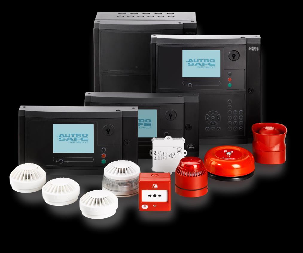
32 System Units 4. System Units Fire Alarm Control Panel Operator Panel System Units BS-420 BS-420M BS-420G BS-420G2 Description BS-420 is a complete fire alarm control panel with full operating capabilities. The panel serves as a operating panel for one or several operation zones. All alarm handling and system features can be controlled and monitored from the panel. The fire alarm control panel is available in three different variants specifically designed for the land market (BS-420), maritime market (BS-420M) and petrochemical oil & gas market (BS-420G) / IEC SIL 2 approval (BS-420G2). The Operator Panel serves as a operating panel for one or several defined operation zones. All alarm handling and system features can be controlled and monitored from this panel. Controller BS-430 BS-430G2 The Controller serves as a connection unit for Loop Driver Modules and I/O modules. Controller Rack Unit BC-420 BC-420G2 The Controller Rack Unit BC-440 serves as a connection unit for the detection loop, alarm sounders, controls and inputs. It is a variant of the BC-420 Controller prepared for rack installations. Together with the IO modules the unit will have the full functionality of the BC-420 Controller. Repeater Panel BC-440 BC-440G2 The Repeater Panel BU-BV-420 serves as both a Fire Brigade Panel and an Information Panel. Settings on a dipswitch determine the type of panel. BU-BV-420 The Fire Brigade Panel allows you to operate alarms related to the relevant operation zone. The Information Panel serves as an indication device only. Page 32
. The maximum power available is 24V/5A.")

33 System Units Power Cabinet System Units BU-BV-420G2 Description It provides information related to the operation zone(s). The Power Cabinet BP-405 provides space for two 12V/18Ah batteries (not included). The maximum power available is 24V/5A. Power Supply Unit BPS-405 / BPS-410 BP-405 BPS-405: 24V/5A power supply BPS-410: 24V/10A power supply Both units include: Power Board BSF-400, including: AutroFieldBus interface 115VAC /230VAC input 6 outputs 24VDC (max. 2A each) 1 fault relay output Page 33
34 Examples of Network Solutions 5. Examples of Network Solutions 5.1 Introduction 5.2 AutroNet Topologies This chapter deals with general guidelines, Ethernet switches, DSL modems, fiber converters and a selection of different examples of network solutions. In the examples the following parameters vary: the type of AutroNet topology (refer to next chapter) the number of system units the use, number and type of switches the use and the number of DSL modems and fiber converters the transmission length between the system units/switches or between the system units/dsl modems/fiber converters the cabling (Cat 5 cable max. 100m, or single-mode/multi-mode optic fibre) AutroNet consists of one of the following network topologies: AutroNet Redundant Star Topology AutroNet Single Star Topology AutroNet Ring Topology 5.3 General Guidelines The smallest network solution consists of two panels (example 1). The use of Cat 5 cable type/category allows a maximum transmission length of 100 meters between panels/switches. The transmission length between two panels using Cat 5 cable type/category can be extended by using Ethernet switches (example 2). A network solution based on Star Topology or Single Star Topology (AutroNet) with more than two panels requires the use of switches (example 3). A network solution based on Ring Topology does not require switches. DSL modems and fiber converters can be used to exceed the transmission lengths between the system units To secure AutroNet redundancy (communication between panels), the origin of power to switches serving one network shall be from a different source than the origin of power to the switches serving the other network, such that a power cable break or power loss in one network will not affect the operability of the other. Transmission lengths that exceed 100 meters require the use of single-mode or multi-mode optic fibre. Page 34
35 Examples of Network Solutions 5.4 Phoenix Ethernet Switches Overview A network solution based on Star Topology or Single Star Topology (AutroNet) with more than two panels requires the use of switches. Only Phoenix Ethernet switches (see table below) are approved and supported by. All Ethernet switches can be used for the Onshore market. Only Ethernet switches that are indicated in coloured rows (the first 9 that are listed) can be used for the Maritime market and the Petrochemical Oil & Gas market. The switch type and the number of switches depend on the actual installation / network design (number of panels and the distances between the panels/switches). For information on current consumption, see chapter Switch type (Phoenix) Description Autronica part number FL SWITCH SFNT 5TX 5 RJ45 ports FL SWITCH SFNT 4TX/FX 4 RJ45 ports 1 fibre optic multi-mode port (SC) FL SWITCH SFNT 8TX 8 RJ45 ports FL SWITCH SFNT 7TX/FX 7 RJ45 ports 1 fibre optic multi-mode port (SC) FL SWITCH LM 5TX 5 RJ45 ports FL SWITCH LM 4TX/FX 4 RJ45 ports 1 fibre optic multi-mode port (SC) FL SWITCH LM 4TX/2FX 4 RJ45 ports 2 fibre optic multi-mode ports (SC) FL SWITCH LM 4TX/FX SM 4 RJ45 ports 1 fibre optic single-mode port (SC) FL SWITCH LM 4TX/2FX SM 4 RJ45 ports 2 fibre optic single-mode ports (SC) RJ45 ports FL SWITCH SFNB 5TX RJ45 ports FL SWITCH SFNB 8TX FL SWITCH SFN 4TX/FX 4 RJ45 ports 1 fibre optic multi-mode port (SC) FL SWITCH SFN 7TX/FX 7 RJ45 ports 1 fibre optic multi-mode port (SC) FL SWITCH SFN 6TX/2FX 6 RJ45 ports 2 fibre optic multi-mode ports (SC) RJ45 ports FL SWITCH SFNB 4TX/FX SM 20 1 fibre optic single-mode port (SC) SFNT: Standard Function Narrow High Temperature Unmanaged Switches LM: Lean Managed Switches Page 35


36 Examples of Network Solutions 5.5 AutroNet Redundant Star Topology Network Solution Example 1 A system equipped with maximum two panels can be installed without the use of any Ethernet switches. In this case, the transmission length between the two panels cannot exceed 100 meters. max.. 100m Network Solution Example 2 The maximum transmission length between the two panels is increased (compared to example 1) by using Ethernet switches to boost the signal. max.. 100m max.. 100m Page 36


37 Examples of Network Solutions Network Solution Example 3 A simple network system. The transmission length between the panels and an Ethernet switch does not exceed 100 meters Network Solution Example 4 The simplest Ethernet switch is equipped with five Tx ports. The switch allows five connections, for example, five panels can be included in a system. Page 37
38 Examples of Network Solutions Network Solution Example 5 If the transmission length between two Ethernet switches exceeds 100 meters, a fibre optic cable can be used to achieve longer distances. Multi-mode optic fibre is a type of optic fibre mostly used for communication over shorter distances, such as within a building. An Ethernet switch equipped with a multi-mode fibre optic port is required. The transmission length depends on the fibre optics cable specifications. Page 38

39 Examples of Network Solutions Network Solution Example 6 If the transmission length between two Ethernet switches exceeds 100 meters, a fibre optic cable can be used to achieve longer distances. Single-mode fibers are mostly used for communication links longer than 1000 metres. The transmission length depends on the fibre optics cable specifications. Page 39
. 5.")
40 Examples of Network Solutions Network Solution Example 7 All AutroSafe panels within a system are linked together using an internal Ethernet network. The AutroSafe system uses the same network to communicate with AutroMaster ISEMS (Integrated Safety and Emergency Management System) Network Solution Example 8 By using a single (two for redundancy) Ethernet switch, up to eight AutroSafe panels can be linked together making one system. Page 40

41 Examples of Network Solutions 5.6 AutroNet Single Star Topology Network Solution - Example 9 As an option, AutroSafe 4 allows also single Ethernet connections to one or several panels in a system consisting of several panels if redundancy is not required. Ethernet 1 must always be used for single Ethernet connections. In the example below all panels have redundant connections to the system, except for the Repeater Panel, which has a single Ethernet connection. Page 41

42 Examples of Network Solutions Page 42
 to Ethernet 2 (Connector J2), from Ethernet 2 to Ethernet 1,")
43 Examples of Network Solutions 5.7 AutroNet Ring Topology Network Solution Example 10 In an AutroNet Ring Topology all panels are connected to each other forming a closed loop. The first panel is connected to the second, the second is connected to the third, and so on, preferably from Ethernet 1 (Connector J1) to Ethernet 2 (Connector J2), from Ethernet 2 to Ethernet 1, from Ethernet 1 to Ethernet 2 and so on. A ring topology is a redundant network, as all panels will continue to operate even with a single break or short-circuit on the ring. Page 43
44 Examples of Network Solutions Network Solution Example 11 A system solution with an AutroNet Ring Topology can communicate with AutroCom (AutroMaster ISEMS or third party equipment) via an Ethernet switch. In this example, the Ethernet switch is connected to the ring between a Fire Alarm Control Panel and a Controller. In the Configuration Tool, AutroCom can be added to either of these two panels, but the one that is chosen must be physically connected to AutroCom, for example, to Ethernet 1 (Connector J1) on the Fire Alarm Control Panel. Page 44
45 Examples of Network Solutions Network Solution Example 12 A system solution with an AutroNet Ring Topology can communicate with AutroCom (AutroMaster ISEMS or third party equipment) via an Ethernet Switch. In this example, a redundant connection to AutroCom is achieved by using two Ethernet switches. One Ethernet switch is connected to the ring between a Fire Alarm Control Panel and a Repeater Panel, the other is connected to the ring between the Controller and the Fire Alarm Control Panel. In the Configuration Tool, AutroCom can be added to the Fire Alarm Control Panel (Ethernet 1, Connector J1) and to the Controller (Ethernet 1, Connector J1). This solution not only provides a redundant connection to AutroCom, it also provides panel redundancy as two panels are connected to AutroCom. Alternatively, a redundant connection to AutroCom can be achieved by adding AutroCom to both Ethernet 1 and Ethernet 2 on the Fire Alarm Control Panel (no panel redundancy). Page 45
46 Examples of Network Solutions Network Solution Example 13 In this example all panels are connected to each other by means of DSL modems and fiber converters in an AutroNet Ring Topology. Page 46
47 Internal Modules 6. Internal Modules 6.1 Module Capacity inside the Fire Alarm Control Panel and Controller Each Fire Alarm Control Panel or Controller provides an internal Power Module, BSS-310 and Communication Module, BSL-310. In addition to these 2 mandatory modules, each system unit can accommodate up to a maximum of 12 optional modules. Refer to the next chapter. The limitation of 12 modules is due to the total capacity in one system unit. Maximum 6 of these modules can be Loop Driver Modules, due to traffic capacity and power consumption. 6.2 Overview The Fire Alarm Control Panel and the Controller can be equipped with the same modules. All outputs are freely programmable from all detectors, manual call points and input signals. All modules have the same dimensions and are easily plugged onto each other on a standard mounting rail inside the unit. Modules in the Fire Alarm Control Panel / Controller Description Loop Driver Module Loop Driver Module Output Module, monitored BSD-310 / BSD-311 BSD-310/N BSB-310A Each Loop Driver Module provides 1 detection loop with 127 loop units. Each Loop Driver Module provides 1 detection loop with 127 loop units. Zone 2 only. Each module provides 4 monitored output circuits (sounder output circuits). May be used for Fire Alarm Devices (FAD), Fire Alarm Routing Equipment (FARE), Fire Protection Equipment (FPE) and other fault outputs. Output Module BSJ-310 The module can be used for relay or LED operation. Each module provides 8 open collector non-monitored outputs. Input Module, monitored BSE-310 Each module provides 4 monitored inputs. Input Module BSE-320 Each module provides 8 non-monitored and galvanic isolated inputs. Communication Module BSL-310 The module serves as an interface for the common internal communication line between the I/O modules. BS-100 Loop Interface BSD-330 The BS-100 Loop Interface, BSD-330 is used as an interface between the AutroSafe detector loop protocol and BS-100 loop protocol. The interface makes it possible to connect BS-panel type detectors to the AutroSafe system, including detectors used in systems BS-3, BS-30, BS-60, BS-80, BS- 90 and BS-100. Power Module BSS-310A The module provides 24V and 5V to the I/O modules. Dual Power Monitoring Module BSS-311 The Dual Power Monitoring Module BSS-311 provides redundant power input to the BSS-310A module Page 47

48 Loop Units 7. Loop Units 7.1 Overview The AutroSafe System offers a wide range of fire alarm detectors, manual call points and input/output units, control units and alarm units that are developed and approved according to European directives (CPD) requiring EN 54 compliance. Both input and input/output units are also available with the SV-function. Input units can also be delivered in series 500 and 500/Ex. For more information on loop units, refer to the Product Catalogue. Detailed information for each loop unit is provided on separate data sheets. 7.2 Detectors The detectors are available both with or without the Self-Verifying Function (SV-function). The system offers the choice of the following three main series: Series 200, standard interactive addressable units. Series 300 with SelfVerify, interactive addressable units. Series 500 with SelfVerify, interactive addressable units designed for use in heavy-duty applications and hazardous areas. The system also offers Exn and Ex ia-approved versions intended for high-risk applications. Smoke detector series S comprise special high sensitive smoke detectors. Each individual detector has a built-in short-circuit isolator. In the event of a short-circuit in the detector cable, the short-circuit location will be isolated as the short-circuit isolator will be activated in the detectors on either side. Page 48

49 Loop Units 7.3 Input and Output Units AutroSafe offers a wide range of input and output units for many different applications. The system features Exn, Exia and Exd approved input and output units for high risk applications. All input and output units feature automatic addressing and short-circuit protection. 7.4 Manual Call Points and Release Stations 7.5 Control Units 7.6 Alarm Units 7.7 Loop Panels AutroSafe offers a wide range of manual call points for different applications, every unit features SelfVerify. Two main series are available: Series 300 with SelfVerify, interactive manual call points. Series 500 with SelfVerify, interactive addressable manual call points designed for use in heavy-duty applications and hazardous areas. The system also offers Exn and Ex ia-approved versions intended for high-risk applications. Autronica offers control units for enabling and disabling of detectors, as well as daytime/nighttime units. Autronica offers a wide range of alarm units for monitoring on detection loops or dedicated alarm outputs. Fire Brigade Loop Panel BU-110 Loop Panels Description The Fire Brigade Loop Panel features the following: Connected and powered by the detector loop The panel presents fire alarms on the display The panel allows Silence and Reset of alarms Information Loop Panel BV-110 BU-110 BV-110 The Information Loop Panel features the following: Connected and powered by the detector loop The panel presents fire alarms, faults and disablements Scrolling function within each window No system operations are allowed (Silence, Reset, menu functions) Page 49

50 Detectors for Special Requirements 8. Detectors for Special Requirements 8.1 Overview Some situations or applications demand a little more from the fire detection system. For these Autronica deliver custom solutions with special detectors. For more information on these detectors, refer to the Product Catalogue. Detailed information for each detector is provided on separate data sheets. 8.2 Aspirating Detectors Aspirating detectors function by sampling air via a network of pipes, sampled air is passed through a dust filter and into a detector chamber where the air is analysed for traces of smoke. The detectors are capable of detecting the small amounts of smoke that are generated in the initial phases of a smouldering fire, ensuring the earliest possible warning of a potential fire while distinguishing real smoke from dust and pollutants, reducing unwanted alarms to a minimum. Every detector is trainable for the specific environment in which it is installed. Typical applications include laboratories, large open spaces, corrosive environments, archives/historical buildings and industrial areas. The AutroSense series are stand-alone detectors, but can also be connected to fire alarm panels. These are highly sensitive detectors with patented artificial intelligence (ClassiFire), which means they are able to adapt to any environment regarding optimal sensitivity, alarm limits and minimum unwanted alarms. Page 50
51 Detectors for Special Requirements 8.3 Flame Detectors 8.4 Beam Detectors Flame detectors are especially suitable for use in connection with the general protection of large open areas where spreading of flames are expected to happen very quickly. They detect radiation from fires, the detection based on ultraviolet radiation (UV radiation), infrared radiation (IR radiation) or a combination of UV and IR radiation. Typical applications are large open areas, such as atria, aircraft hangars and shopping centres as well as storage rooms for flammable substances. Beam detectors are used in large open areas instead of a quantity of point smoke detectors. The detector protects a given area by sending signals (infrared light beam) between a transmitter and receiver, and detect dimmer or changes in frequency by heat or smoke. Beam detectors are suited to applications in open spaces where costs associated with point smoke detectors would be prohibitive. Typical applications include warehouses, hotels, hospitals, schools, public buildings, etc. Page 51
52 Communication Modules 9. Communication Modules Autronica provides a large range of communication modules: AutroFieldBus Protocol Converter BSD-321; interfacing AutroFieldBus and AL_Com+ AutroSafe Communication Module BSL-310; interfacing the common internal communication line between all the different I/O modules Multi Mode Fibre Optic Converter BSL-321; amplifier for AutroFieldBus networks. Single Mode Fibre Optic Converter BSL-322; amplifier for AutroFieldBus networks. AUTROLON/AutroFieldBus Communication Amplifier, BSL-325; amplifier for communication signals on networks AutroSafe BU-70 Interface Module BSL-337; enables connection of BU-70/BU-100/BU-101 (BS-100 systems) to AutroSafe. In addition, Autronica provides integrated fire and gas modules intended for the oil & gas market (refer to Product Catalogue and separate datasheets). Furthermore, Autronica provide the AutroSafe OPC Server, enabling communication between several fire detection systems and other control systems. The solution improves the compatibility between AutroSafe and surveillance systems from other manufacturers. For more information on these communication modules, refer to the Product Catalogue. Detailed information for each module is provided on separate datasheets. Page 52
53 BRANNALARM Tilpasningsenhet FIRE ALARM Interface unit Nr. No. BRANNALARM Tilpasningsenhet FIRE ALARM Interface unit Nr. No. KNUS G LAS SE T TRYKK HER PRESS H ER E BREAK G LASS Detection Loops 10. Detection Loops 10.1 Description A detection loop is connected directly to the Loop Driver Module. A maximum of 6 Loop Driver Modules can be installed in one Controller or Fire Alarm Control Panel. The detection loop must be wired as a loop. This installation method provides optimum safety. The cable for the detection loop must be in accordance with local/national regulations. Note that all types and series of AutroSafe detectors, manual call points and I/O units can be connected to the same detection loop. Detectors, manual call points and input/output signals are freely programmable during system configuration. Detector I/O Unit BN- 320 Manual Call Point Loop Driver Module BN Branch-offs For optimum safety and as a general rule, the detection loop must be wired as a loop. If necessary, a branch-off can be connected to a detection loop if the existing cable layout requires this, but this is not recommended, as the safety will be reduced. To ensure a correct addressing of the detectors on a branch-off when configuring the system, there can not be more than one branch-off per detector. For safety reasons, the number of detectors on each branch-off must be kept to a minimum (a maximum of 32 detectors on each branchoff), as the detectors on a branch-off will not operate in case of a break og shortcuit on the branch-off. Accepted NOT Accepted! Branch-off Branch-off Loop Loop Branch-off Page 53
54 Detection Loops 10.3 Capacity on the Detection Loop Maximum Loop Units There can be a maximum of 127 loop units per detection loop. A loop unit is defined as a point (detector or manual callpoint, an I/O unit or an Electronic Sounder) that is connected to a detection loop Current Consumption The table below shows the current consumption for loop units in normal status and in alarm status. A detector with active LED indication will also draw current on the detection loop. In a configuration where it is required that several LEDs must be activated simultaneously, the number of detectors on the loop must be reduced. Loop Unit Detector, Manual Call Point and I/O Unit Electronic Sounder (BBR-200) Current Consumption in Normal Status 0,3mA 0,3mA Current Consumption in Alarm Status 0,3mA 5mA The maximum number of activated LEDs is 6 when using Loop Driver Module BSD-310, and 18 when using the Loop Driver Module highpower version BSD-311. Loop Driver Module BSD-310 (standard version) BSD-311 (high-power version) Maximum Current Consumption 100mA 200mA Page 54
55 Detection Loops Guidelines Scores To easily estimate the type of loop driver module to be used and the maximum length of the detection loop when projecting, each type of loop unit is given a score. Each detector, manual callpoint or I/O unit is to be given 1 score. Each electronic sounder is to be given 15 scores. Type of loop driver module The type of loop driver module (standard or high-power version) to be used depends on the total number of scores. Total no. of scores Type of loop driver module BSD BSD BSD-311 > 600 Not allowed. Maximum lenght of detection loop The table below shows the maximum length of the detection loop based on the cable dimension and the total number of scores (2-wire cable measured from output to input). BSD-310 BSD-311 Cable dimension Scores Scores Scores ,75mm2 1100m 660m 430m 1mm2 1470m 880m 580m 1,5mm2 2200m 1320m 870m 2mm2 2940m 1760m 1160m 2,5mm2 3670m 2200m 1450m Example - using Scores to Estimate A detection loop consists of 60 detectors, 10 manual callpoints, 14 electronic sounders and 10 I/O units, which adds up to 94 loop units (below the limit of 127). The following scores apply: 60 detectors: 60 scores 10 manual callpoints: 10 scores 14 electronic sounders: 210 scores 10 I/O units: 10 scores Total number of scores: 290 scores In this example, the total number of scores is below 300, and the standard loop driver module BSD-310 can thus be used. The maximum length of the detection loop for various cable dimensions is Page 55
56 Detection Loops shown in the second column of the table above (within the range of scores) Example using Exact Values to Calculate A detection loop consists of 86 detectors, 10 manual callpoints, 5 I/O units and 26 electronic sounders, which adds up to 127 loop units (within the limit of 127). 86 detectors: 86 x 0,3mA= 25,8mA 10 manual callpoints: 10 x 0,3mA= 3mA 5 I/O units: 5 x 0.3mA= 1,5mA 26 electronic sounder: 26 x 5mA= 130mA Total current consumption: 160,3mA In this example, the high-power loop driver BSD-311 is required, as the total power consumption is > 100mA and <200mA (see table below). The calculation is based on values measured in alarm status (worst case). Loop Driver Maximum Current Consumption Maximum resistance ( ) / capacitance (F) BSD-310 (standard version) 100mA Standard loop driver module BSD-310: Rmax=50 total and Cmax=0,5 F BSD-311 (high-power version) 200mA High-power version BSD-311: Rmax=20 total and Cmax=0,5 F The cable type, cable dimension and maximum cable length, plus the maximum resistance and capacitance is included in the table below (refer to Cable Specifications, chapter 11). As the high-power version BSD-311 is required in this example, the maximum resistance is Rmax=20 total and the maximum capacitance is Cmax=0,5 F. Cable type / category Cable dimension Maximum cable length (m) Maximum resistance ( ) / capacitance (F) 2 x 0,75mm 2 18 AWG 400m High-power version 2 x 1,5 mm 2 15 AWG 800m 2 x 2,5 mm 2 13 AWG 1320m Note that when measuring the total resistance on the detection loop, always measure the resistance on the plus-wire and multiply the measured value by 2. BSD-311: Rmax=20 total and Cmax=0,5 F Page 56
57 Detection Loops Example Calculating the Exact Cable Length The following equation can be used to calculate the exact cable length of a detection loop: L = the total cable length r+ = the resistance on the plus-wire (<10 ) A = the cable dimension (mm 2 ) ρ = the specific resistance of copper (0,017) r+ x A L = = ρ r+ x A 0,017 Example: L = 10 x 1,5mm2 ~ 882m 0,017 x mm2 m The cable dimension (1,5mm 2 ) and calculated cable length (882m) requires the use of the high-power loop driver module version BSD-311 (as shown in the shaded row in the table below). Cable type / category Cable dimension Maximum cable length (m) Maximum resistance ( ) / capacitance (F) 2 x 0,75mm 2 18 AWG 400m High-power version 2 x 1,5 mm 2 15 AWG 800m 2 x 2,5 mm 2 13 AWG 1320m BSD-311: Rmax=20 total and Cmax=0,5 F Page 57
58 Cable Specifications 11. Cable Specifications For the complete information on cable specifications, refer to Cable Specifications, part number 116-P-ASIFGCABLESPEC/CGB (file name: asafeifgcable_cgb). For specific information on cable specifications for integrated fire and gas detection systems, refer to the separate IFG handbook; System Design and Engineering, 116-P-SYSDEENGIN-IFG/XGB. Page 58

59 Shielding and Earthing 12. Shielding and Earthing 12.1 Definitions The shielded cable shall be connected to the instrument earth (IE) at one end and left floating at the other end. Local Frame Earth The electrical connection to the framework at the described physical position, such as the frame or chassis of a cabinet, the power cable outlet etc. Shield Conductive structure encapsulating the wire in a harness or cable, normally in the form of a mesh or foil forming a Faraday cage. Armour Mechanical protection to avoid physically damaging electrical cables or circuits. Instrument Earth (IE) An earth reference that is normally used to reference measurements of electrical signals. It may be the same as the Protective Earth (single earthed systems). Protective Earth (PE) An earth reference that is normally used as a coupling path for unwanted electrical signals, like transients and over-voltage. The chassis or framework of the installation is normally considered to be the local Protective Earth. As the name implies, it is intended to provide a safe electrical potential for human safety. Ground Synonym for Earth, in this handbook Earth is used. Page 59
60 Shielding and Earthing 12.2 Single Earth Systems - PowerLoop Firstly, consider a Single Earth system for simplicity. Please note that an Integrated Fire and Gas system with PowerLoop shall by no means be designed as a single earth system. Refer to section 12.3 for details about keeping the PowerLoop as a dual earth system. 1) All PowerLoop cabling shall be shielded. Every segment of the PowerLoop cable has to be protected by a shield that effectively attenuates the radiated field from the cable. The shielding is required to avoid radiated emissions and hence crosstalk from one PowerLoop to any other. Armouring is normally not considered to be a sufficient shield. 2) Shield shall be terminated at one end only. The shield shall be terminated close to the BSD-340 PowerLoop Driver. As the cable forms a full loop, the return path of the cable shield shall not be terminated. No electrical connection to earth shall be made anywhere in the system, i.e. the units shall be installed and galvanically isolated from the chassis. The termination of the shield will be defined by the site installation, to a earth terminal in the cabinet or similar. PLA+ 6 PLA- 7 IE 8 BSD-340 IE PLB+ 9 PLB- 10 Max 30 cm 3) Maximum permissible non-shielded length of cable - 30 cm This implies that the internal cabling in a rack or enclosure where the BSD-340 and / or the Loop Units are installed also needs to be fully shielded. The requirement includes termination / junction boxes and all field wiring as well. Page 60
61 Shielding and Earthing 4) Shield shall be continuous The PowerLoop cable will be split in two segments, separated by field equipment including junction boxes or Loop Units. The shield shall be continued through these separations. There shall be no electrical connection to the local frame earth. In the following figure the junction boxes includes a strap / jumper to continue the shield between the cable segments (these straps / jumpers should be made of a suitable low-impedance cable). PLA+ 6 PLA- 7 IE 8 BSD-340 IE PLB+ 9 PLB- 10 Note jumper! If there are break-outs from the main loop (to make local small loops that return to the same break-out box), care shall be taken to avoid local closed loops. See the figure below. PLA+ 6 PLA- 7 IE 8 BSD-340 IE Break! PLB+ 9 PLB- 10 5) Maximum cable length The PowerLoop Calculator will define the maximum length of each cable segment, this tool however determines length only from the power loss of the specified cable. The cable or wire capacitance will not affect the cable length as much as the resistive loss will restrict the power, not the communication. Page 61
62 Shielding and Earthing 12.3 Dual Earth Systems - PowerLoop PowerLoop installations use both Instrument Earth (IE) and Protective Earth (PE) as two separate earthing paths. In this case, the shield (inner layer of cable) shall be continuous and earthed at one end only. The outer braid, shield or armour, is then connected to the Protective Earth connection. This will normally be the local connection point to the PE, the chassis of the cabinet or a chassis connection close to the field equipment. The two earth systems shall be kept isolated. PLA+ 6 PLA- 7 IE 8 BSD-340 IE PE PE PLB+ 9 PLB- 10 PE will make earth loops as they are terminated at multiple points, however the loop area will be narrow or closed as the armour will be close to the frame or earth. It is essential that the armour is kept on the same equipotential around to avoid EMC problems or large current flow in the PE. PE may be connected through glands to the junction boxes to form a continued protective armour or shield. Still the internal shield and IE shall be kept isolated from the PE. Page 62
63 Shielding and Earthing 12.4 Shielding and Earthing AutroFieldBus A description of the local earthing requirements for each unit that may be connected to AutroFieldBus is included in the respective datasheets. In the total system overview, some key issues needs to be taken care of: Shielded cable is recommended. There are no absolute requirements for shielding, however if severe electromagnetic interference is expected, shielding should be applied. Unshielded cable may be used inside the cabinet. If shielded cable is used, the shield shall be kept continous. Care should be taken to avoid earth/shield loops. As a guideline, connect the shield to the B-side of the AutroFieldBus Driver EAU- 341 / Controller Board BSA-400 and not to the A-side. If segments of the AutroFieldbus cable is isolated, as it will be when including BSL-325 Booster, BSL-321 Multimode Fiber or BSL-322 Single Mode Fiber, local earthing of the isolated segments is required. See figure for example. We follow the cabling counter-clockwise: BSD-340 AFB-A AFB-A AFB-CT BSL- 322 Fiber BSL- 322 EAU-341 / BSA-400 IE 1 AFB-B AFB-B AFB-CT BSL BSD Junction Box The cable shield is referenced to earth at Earthpoint 2 according to the guidelines above. Through the BSD-340 the shield is continued. There s a galvanic isolation in the Booster (BSL-325) that makes the cable (on the right side) floating. To avoid this, the Center Tap of the transformer of the AutroFieldBus (internal in the BSL-325) is terminated to the local Earth at Earthpoint 3. An alternative is to rather bring the reference from the other side of the Booster across it, to continue the shield in that way. Note that the bus needs to be referenced by connecting the CenterTap (pin 3 or 6) to Earth. On the left side, this is ensured by the AFB-CT to Earth at the EAU-341 / BSA-400, while the BSL-325 right side needs to be tied to Earth or to the reference of It s left side, by for instance connecting pin 3 to 6. Further on, the BSL-322 to BSL-322 also isolates. If there had been several fiber jumps, each individual cable segment between the fiber segments would have to be earthed. In this case, the segment following passes through a BSD-340, the shield is kept continous and it is referenced to earth at Earthpoint 1, close to the EAU-341 / BSA An alternative to this would be to terminate at the other end of this segment, at the BSL-322. Page 63
64 Shielding and Earthing The main rule is: Ensure that all segment s shield are terminated at one end and one end only. Dual Earth systems acts similar to the description of the PowerLoop, as long as the inner Instrumental Earth shield is kept according to the above rules, the outer protective shield may be terminated at multiple locations Earth Fault Detection - AutroFieldBus The Earth Fault detection mechanism monitors the cable segment that is electrically connected to the AutroFieldBus Driver EAU-341 / Controller Board BSA-400. However, if the cable is interrupted electrically by a BSL-325 Booster or a Fibre modem, these segments may need additional Earth Fault Monitoring. This may be achieved by including a BSD-321 into this segment, and enable the Earth Fault Monitoring at this device. Care shall be taken to avoid two units monitoring the same segment, as they may interfere with each other on this feature. All earth fault monitoring is done towards Instrument Earth (IE) in the units. Page 64
65 Power Distribution, Calculation and Consumption 13. Power Distribution, Calculation and Consumption 13.1 Introduction The power supply provides power to AutroSafe, AutroSafe s existing I/O module stacks, battery monitoring and charging, plus 24 voltage contacts for other external equipment. 2 x 24V outputs of 2A to AutroSafe panel 2 x 24V outputs of 2A to I/O stack 2 x 24V outputs of 2A to third-party equipment 1 input for battery 1 input for battery charger Communication Power control for battery Control signals for battery charger All internal voltage levels are monitored Temperature sensor for compensation of charger voltage Power Supply Interfaces / Connections 24 V Control signals Autro Safe AFB (Autro- FieldBus) 24 V Switches for I/O Stack 24 V 24 V I/O Stack Contact, 24V/2A Contact, 24V/2A 24 V Temperature 3rd party power outputs Battery Page 65
66 Power Distribution, Calculation and Consumption The Power Cabinet BP-405 supplies a maximum of 5A, of which 3A is available for the fire detection system. 2A is used for the charging and maintenance of the battery. Note that the maximum load for each output (A1, A2, B1, B2, C1, C2) is 2A. Output A supplies 2A and functions as a single output for all Controllers BC-420 and panels (BS-420, BS-430, BU-BV-420). Output C supplies 2A to the internal modules mounted on the rail inside the Controller BC-420 and Fire Alarm Control Panel BS-420. Note that if there is a maximum load from both output A and C, the total load would be 4A, which in this case would exceed the limit of 3A. It is therefore important to calculate the total power consumption for each Power Cabinet BP-405 to ensure that this limit is not exceeded. The example described in the next chapter shows how you can easily find out if the power consumption in a system is within the given limits Power Calculation Example 4 Power Cabinets BP-405 Power Cabinet 1 A1 Panel BS-420 and BC ma A2 Panel BS-420 and BC-420 B1 External Fibre converters 2x LM 4TX/2FX B2 External Fibre converters 2x LM 4TX/2FX 800 ma Internal 1860 ma C1 modules (I/O stack) BS-420 and BC-420 C2 Total power consumption 3380 ma All outputs in Power Cabinet 1 are correctly set up for redundancy and are below the limit of 2A. However, the total power consumption is 3,38A, meaning that the limit of 3A is exceeded by 0,38A. The total power consumption must be reduced by 0,38A, or another power cabinet has to be added. Page 66
67 Power Distribution, Calculation and Consumption Power Cabinet 2 A1 Panel 2 x BC ma A2 Panel 2 x BC-420 B1 External B2 External Internal modules 1860 ma C1 (I/O stack) 2 x BC-420 C2 Total power consumption 2580 ma Power Cabinet 2 is correctly set up, as no outputs exceed the limit of 2A and the total power consumption is 2,58A, i.e. below the limit of 3A. In order to reduce the total power consumption for Power Cabinet 1 to 3A (the limit), one of the fibre converters powered from Power Cabinet 1 can instead be powered from Power Cabinet 2. The total power consumption for Power Cabinet 1 will then be reduced by 400mA to 2980mA (<3A). Both Power Cabinets will now have a total power consumption within the limit of 3A. Power Cabinet 3 A1 Panel BU-BV ma A2 Panel BU-BV-420 B1 External Various additional external equipment 24V 500 ma B2 External Equipment that does not require redundancy 750 ma C1 Internal modules (I/O stack) C2 Total power consumption 1470 ma A Repeater Panel BU-BV-420 is powered from a Power Cabinet 3. Power Cabinet 3 supplies redundant power to the Repeater Panel BU- BV-420. In addition, it supplies power to equipment that does not require redundant power. If redundancy is not required, power can be supplied from one output (for example, output B1 or B2). Output C1 or C2 cannot be used to other equipment, as this output is shut off 3 seconds during an initialization of the system. Power Cabinet 4 A1 Panel 1x BC ma A2 Panel 1x BC-420 and BS-420 B1 External Various relays and door magnets B2 External Various relays and door magnets 2500 ma Internal 2300 ma modules C1 (I/O stack) BC-420 and BS-420 C2 BC-420 and BS-420 Total power consumption 5480 ma Page 67
68 Power Distribution, Calculation and Consumption The power distribution from Power Cabinet 4 is not according to legal specifications of the Power Cabinet BP-405. BS-420 is not supplied with redundant power. Power must also be supplied from output A1. The power consumption from output C1 and C2 exceeds the limits. The internal modules (I/O stack) draw too much power. The total power consumption exceeds 3A. Power consumption status: Output A The power consumption is below the limit (2A), but the BS-420 must have redundant power, and thus must be supplied with power from A1. Output B More than 2A is supplied to equipment that does not require redundant power. This means that this output can supply a maximum of 4A (2A + 2A). Output C This connection is not satisfactory as the power consumption is above 2A. Conclusion: The total power consumption (5480mA) related to the power distribution in Power Cabinet 4 is far too high. More power must be supplied. A separate power supply can be used to supply power to equipment that does not require redundancy. If the power consumption is reduced by 2,5A, power supplied from Power Cabinet 4 will be sufficient, as the power needed is no longer exceeding the total limit of BP-405. Port C is still above 2A and must be reduced either by removing components that are not needed or by using an additional Power Cabinet BP Power Consumption System Units System Unit Fire Alarm Control Panel BS-420 Controller BC-420 Repeater Panel BU-BV-420 Operator Panel BS-430 Power Board BSF-400 Current Consumption 156mA/27,2VDC (idle) Max. 340mA/27,2VDC (lamp test) 156mA/22,2V DC (idle) Max. 220mA/27,2V (lamp test) 175mA/27,2V DC (idle) Max. 340mA/27,2V DC (lamp test) 85mA Page 68
69 Power Distribution, Calculation and Consumption Loop Units For information on the current consumption for various loop units, refer to technical specifications provided in the relevant datasheets Phoenix Ethernet Switches Switch type (Phoenix) The current consumption for each Phoenix switch is shown in the rightmost column below. Description Autronica part number Current Consumption 24V DC FL SWITCH SFNT 5TX 5 RJ45 ports mA FL SWITCH SFNT 4TX/FX 4 RJ45 ports 1 fibre optic multi-mode port (SC) mA FL SWITCH SFNT 8TX 8 RJ45 ports mA FL SWITCH SFNT 7TX/FX 7 RJ45 ports 1 fibre optic multi-mode port (SC) mA FL SWITCH LM 5TX 5 RJ45 ports ma FL SWITCH LM 4TX/FX 4 RJ45 ports 1 fibre optic multi-mode port (SC) mA FL SWITCH LM 4TX/2FX 4 RJ45 ports 2 fibre optic multi-mode ports (SC) mA FL SWITCH LM 4TX/FX SM 4 RJ45 ports 1 fibre optic single-mode port (SC) mA FL SWITCH LM 4TX/2FX SM 4 RJ45 ports 2 fibre optic single-mode ports (SC) mA FL SWITCH SFNB 5TX 5 RJ45 ports FL SWITCH SFNB 8TX mA FL SWITCH SFN 4TX/FX 4 RJ45 ports 1 fibre optic multi-mode port (SC) mA FL SWITCH SFN 7TX/FX 7 RJ45 ports 1 fibre optic multi-mode port (SC) mA FL SWITCH SFN 6TX/2FX 6 RJ45 ports 2 fibre optic multi-mode ports (SC) mA FL SWITCH SFNB 4TX/FX SM 20 4 RJ45 ports 1 fibre optic single-mode port (SC) mA Page 69
70 Appendix 14. Appendix 14.1 Zoning Concept General To describe the functional hierarchy of the system we use the term "zone". Assigning system components to zones enables hierarchical control from detection to activation of alarm. This hierarchy consists of the following zones: Detection Zone (DZ) Alarm Zone (AZ) Operation Zone (OZ) Fire Alarm Control Panels Operator Panels Information Panels Repeater Panels Points (Detectors / Manual Call Points Input signals) Detection Zone Operation Zone Alarm Zone Sounders Detection Zone A Detection Zone (DZ) is defined as a zone with one or more points (detectors or manual call-points) that logically belong together, determined by geographical/functional parameters (for example, the sales department on the second floor). A point can only be assigned to one detection zone, and can only refer to one specific location in the system (for example, a specific office on the second floor in a building). The Detection Zone will be the trigger to generate outputs to the Alarm Zone. Page 70
71 Appendix Alarm Zone An Alarm Zone (AZ) is activated by one or several detection zones. Example: An alarm from one of the devices in DZ3 will activate sounders in AZ1. Within the same alarm zone, alarm sounders give the same audible signal. Geographically associated alarm zones can be defined as neighbour zones, such that these can operate outputs for alarm zones adjacent to the incident Operation Zone An Operation Zone (OZ) defines the scope of an Operator Panel. The operation zone can cover one floor or one building, and is designed to restrict the operators sphere of influence on the system as a whole. At least one Fire Alarm Control Panel / Operator Panel should have the overall control of the system. Operation zones on higher levels may encompass several other operation zones. Input / Output units (for example, Door Control Units, Sprinkler Control Units etc.) can be controlled from an Operation Zone. An Operation Zone given these properties and necessary parameter settings is referred to as a Control Operation Zone. Different day / night operation for different areas (i.e. detection zones) requires the use of several Operation Zones / sub-operation zones with different Day / Night Operation. An Operation Zone given these properties and necessary parameter settings is referred to as a Day / Night Operation Zone. Page 71


72 Appendix 14.2 Configuration Examples Simple Configuration Example The simple configuration example is based on the AutroSafe Demo Board configuration, and it looks like this: BS-420 Page 72
AUTROSAFE. An interactive fire detection system for larger vessels
 AUTROSAFE An interactive fire detection system for larger vessels AUTROSAFE AutroSafe interactive fire detection system is designed for the toughest requirements and expands the possibilities of a fire
System Design and Engineering AutroSafe Interactive Fire & Gas Detection System (IFG)
") System Design and Engineering AutroSafe Interactive Fire & Gas Detection System (IFG) 116-P-SYSDEENGIN-IFG/XGB, Rev. A, 2015-08-14, Autronica Fire And Security AS COPYRIGHT This publication, or parts thereof,
System Design and Engineering AutroSafe Interactive Fire & Gas Detection System (IFG) 116-P-SYSDEENGIN-IFG/XGB, Rev. A, 2015-08-14, Autronica Fire And Security AS COPYRIGHT This publication, or parts thereof,
AUTROSAFE 4 A new level in interactive fire detection systems
 AUTROSAFE 4 A new level in interactive fire detection systems Autronica Fire and Security AS Protecting life, environment and property... Proven, reliable and now even better AutroSafe 4 the next generation
AutroSafe interactive fire detection system AUTROSAFE. An interactive fire detection system for complex installations
 AutroSafe interactive fire detection system AUTROSAFE An interactive fire detection system for complex installations AUTROSAFE AutroSafe interactive fire detection system is designed to meet the toughest
System Description Autroprime Interactive Fire Detection System
 System Description Autroprime Interactive Fire Detection System 116-P-APRIME2-SYSTEM/XGB, Rev. B, 2018-03-23, Autronica Fire And Security AS COPYRIGHT This publication, or parts thereof, may not be reproduced
Not to be distributed outside of FM Approvals and its affiliates except by Customer APPROVAL REPORT. BU-110 and BV-110 Loop Based Displays
 Not to be distributed outside of FM Approvals and its affiliates except by Customer APPROVAL REPORT Project No: 0003053331 Supplements Project No.: 3034449 Class: 3010 Product Name: BU-110 and BV-110 Loop
Operator's Handbook. Release 3. Fire Alarm Control Panel, BS-310 / 320 / Operator Panel BS-330. System Program Version 3.8.0
 Release 3 System Program Version 3.8.0 Operator's Handbook Fire Alarm Control Panel, BS-310 / 320 / Operator Panel BS-330 Protecting life, environment and property... ASAFE-FO/FE Rev. I, 2009-02-27 COPYRIGHT
Operator's Handbook. Interactive Fire Alarm System Release 3. Information Panel, BV-320. Protecting life, environment and property...
 Interactive Fire Alarm System Release 3 Operator's Handbook Information Panel, BV-320 Protecting life, environment and property... ASAFE-IN/FE Rev. A, 010531 COPYRIGHT This publication, or parts thereof,
Панели. AutroSafe 4. Технические характеристики
 Панели AutroSafe 4 Технические характеристики Архангельск (8182)63-90-72 Астана +7(7172)727-132 Белгород (4722)40-23-64 Брянск (4832)59-03-52 Владивосток (423)249-28-31 Волгоград (844)278-03-48 Вологда
System Description AutroMaster V Presentation System
 System Description AutroMaster V Presentation System AMASTERV-SYSTEM/XGB, Rev. B, 2018-05-07, Autronica Fire And Security AS COPYRIGHT This publication, or parts thereof, may not be reproduced in any form,
System Description AutroMaster ISEMS - Integrated Safety and Emergency Management System
 System Description AutroMaster ISEMS - Integrated Safety and Emergency Management System 116-P-AMASTER-SYSTEM/XGB, Rev. C, 2016-05-20, Autronica Fire And Security AS COPYRIGHT This publication, or parts
DUAL MONITORED INPUT/OUTPUT UNIT BN-305
 DUAL MONITORED INPUT/OUTPUT UNIT BN-30 Interactive fire detection systems Product Datasheet Features Interactive For interfacing and controlling external units to Autronica s interactive fire detection
Shortform Configuration Guide
 Interactive Fire Alarm System Release 3 Shortform Configuration Guide AutroSafe Configuration Tool For the AutroSafe Demo Board Protecting life, environment and property... P-ASAFE-SH/VE Rev. B, 010531
Different types of Fire Alarm System
 Different types of Fire Alarm System Conventional Fire System Generally comes with Zones. Each zone can have max 20 detectors. Addressable Fire Alarm System This comes in loops. Different manufacturer
Installation Handbook. Interactive Fire Alarm System Release 3. Operator Panel, BS-330. Protecting life, environment and property...
 Interactive Fire Alarm System Release 3 Installation Handbook Operator Panel, BS-330 Protecting life, environment and property... P-ASAFE/OP/DE Rev. A, 010531 COPYRIGHT This publication, or parts thereof,
DUAL MONITORED INPUT/OUTPUT UNIT BN-305-2
 DUAL MONITORED INPUT/OUTPUT UNIT BN-305-2 Interactive fire detection systems Product Datasheet Features Interactive For interfacing and controlling external units to Autronica s interactive fire detection
Autronica Fire and Security AS ID:
 1 1 Autronica Fire and Security AS A leading innovator, manufacturer and supplier of fire & gas detection equipment Founded in 1957 in Trondheim, Norway Protecting life, environment and property 2 Fire
GE Security. FP1200, FP2000 and KSA1200 series fire panels, repeaters and emulators Interconnection and wiring
 GE Security FP1200, FP2000 and KSA1200 series fire panels, repeaters and emulators Interconnection and wiring Version v2-2 / September 2005 Aritech and Kilsen are GE Security brands. http://www.geindustrial.com/ge-interlogix/emea
The EN54 Part 2, 4 and 13 Fire System
 Scope of work: To design, supply, install and commission an Analogue Addressable Fire Alarm Control System in accordance with the details specified herein and in accordance with supplied drawings The EN54
KFP-CF Series Operation Manual
 KFP-CF Series Operation Manual P/N 501-415103-2-31 REV 03.10 ISS 13NOV13 Copyright Trademarks and patents Manufacturer Version Certification European Union directives Contact information 2013 UTC Fire
SINGLE MONITORED INPUT UNIT BN-303
 SINGLE MONITORED INPUT UNIT BN-303 Interactive fire detection system Product Datasheet Features Interactive For interfacing switches and 3rd party detectors with relay outputs to Autronica s interactive
MINERVA. Marine. Fire Detection. MX T2000 Panel Range. Features: MINERVA Marine Panel Range
 Fire Detection MINERVA Marine MX T2000 Panel Range Features: Enhances fire detection and eliminates unwanted alarms using fuzzy logic Assists fire fighting and training by providing on-screen risk management
ZX1e ZX2e ZX5e. Document No Issue 01 user manual
 ZX1e ZX2e ZX5e Document No. 996-130 Issue 01 user manual MORLEY-IAS ZX2E/ZX5E Fire Alarm Control Panels Table of Contents 1 INTRODUCTION... 4 1.1 NOTICE... 4 1.2 WARNINGS AND CAUTIONS... 4 1.3 NATIONAL
Instructions AutroFlame IR Flame Detector BG-201/BG-21
 Instructions AutroFlame IR Flame Detector BG-201/BG-21 116-P-BG201-BG21/DGB 2012-10-10 COPYRIGHT This publication, or parts thereof, may not be reproduced in any form, by any method, for any purpose. and
The system is expanded via the RCC network with each RCC capable of passing information to and from up to 31 detection or output devices.
 FireCell Radio Hub Fully addressable Wireless activation Third party approved (EN54) 2-way radio communication Loop powered Diagnostics port Range in excess of 150 metres Overview The model FCX-500-001
The EN54 Part 2 & 4 Fire System
 Scope of work: To design, supply, install and commission an Analogue Addressable Fire Alarm Control System in accordance with the details specified herein and in accordance with supplied drawings The EN54
For Complete Fire and Gas Solutions
 Industrial Fire For Complete Fire and Gas Solutions 2 The Total Package What do you need from an integrated fire and gas system? In industrial fire and gas environments it s important to have a reliable
Fire alarm system EBL512 G3
 Fire alarm system EBL512 G3 An analog addressable fire alarm system for early detection - without any unwanted alarms. Third generation. www.panasonic-fire-security.com 2010-04-23 Page 1 of 6 The demands
Protecting life, environment and property... PRODUCTS 2012 Oil & Gas
 Protecting life, environment and property... PRODUCTS 2012 Oil & Gas Contents AutroSafe IFG...4 Panels AutroSafe 4... 6 Panel kits AutroSafe 4... 7 Switches... 8 Printer... 9 Panels AutroSafe 3... 10 Spare
Consultant Specification AGILE Wireless Fire Detection System
 Contents Scope of Work... 2 The EN54 Part 2 & 4 Fire System... 2 Standards... 2 Wireless Intelligent Photoelectric Smoke Detector Specification... 4 Wireless Intelligent Thermal Heat Detector Specification...
Intelligent Security & Fire Ltd
 Product Data Sheet Mx-4000 Series User Manual MX-4100, MX-4200, MX-4400, Mx-4400/LE & Mx-4800 Fire Alarm Control Panels The operation and functions described in the manual are available from Software Versions
On the job around the clock 24/7: Fire detection systems
 On the job around the clock 24/7: Fire detection systems Version 02.2010 Version: 02.2010 Product catalogue Fire detection systems This product catalogue is intended for sales purposes only. For planning,
SUPREMATouch. Modular Fire & Gas Detection System
 SUPREMATouch Modular Fire & Gas Detection System Tel: +44 (0)8 9388 Email: info@ Fire & Gas Detection Solutions MSA permanent gas detection systems are used throughout the world to protect plant and personnel
Halton SAFE / 7.14 user guide and installation instructions
 Halton SAFE / 7.14 user guide and installation instructions VERIFIED SOLUTIONS BY H A LTO N Enabling Wellbeing Table of contents 1 System description 3 2 User Accounts 4 3 Main menu 7 3.1 Main menu - Change
Autronica Fire and Security PRODUCTS Fire and gas safety Division Maritime
 Autronica Fire and Security PRODUCTS 2017 Fire and gas safety Division Maritime Autronica Fire and Security is a leading innovator, manufacturer and supplier of fire and gas safety worldwide. Our products
FC330A-ECO1 Auto-addressing analogue 1-Loop fire detection panel
 FC330A-ECO1 Auto-addressing analogue 1-Loop fire detection panel Synova Commissioning in no time thanks to automatic address allocation Auto-addressing makes setting dip switches, punch cards, etc. unnecessary
Dryer Controller M720
 User Manual Dryer Controller M720 Hardware version 2.00 Software version 2.00 Manual M720 Dryer controller Page 1 of 60 Document history Preliminary version: - Created in April, 2009 Hardware Version 2.00,
SERVICE INSTRUCTIONS FOR. Fire Alarm System MINI-2000
 SERVICE INSTRUCTIONS FOR Fire Alarm System MINI-2000 Version 1.3 02.04.1998 Jari Ollila Tom Brunberg Oy Esmi Ab Copyright Oy ESMI Ab, 1991... 1998 The copyright to the documentation herein is the property
Laptop / PC Programming Manual
 Laptop / PC Programming Manual Doc. # Fire PC Program rev B 01.07 This Document is property of Evax Systems, Inc. The Evax Fire Solutions Programmer Components 2 1.0 System Setup 4 1.1 Interface Setup
User Manual. Dryer Controller M720
 User Manual Dryer Controller M720 Hardware version 1.00 Software version 1.00 Preliminary version Manual M720 Dryer controller Page 1 of 42 Document history Preliminary version: - Created in April, 2009
Autronica Fire and Security PRODUCTS Fire and gas safety Division Maritime
 Autronica Fire and Security PRODUCTS 2016 Fire and gas safety Division Maritime Autronica Fire and Security is a leading innovator, manufacturer and supplier of fire and gas safety worldwide. Our products
PRODUCTS 2014 Autronica Fire and Security AS. Protecting life, environment and property
 Protecting life, environment and property PRODUCTS 2014 CONTENTS AUTROSAFE 4 FIRE DETECTION SYSTEM...4 Panels.... 6 Panel kits.... 7 Switches... 8 Printer... 9 Modules.... 10 Communication... 12 Service
HART XL High Sensitivity Smoke Detection
 High Sensitivity Smoke Detection The Hart XL High Sensitivity Smoke Detection system (HSSD) is an aspirating fire detection system designed to give very early indication of an incipient fire condition.
Intelligent Security & Fire Ltd
 full installation, commissioning and operating manuals can be downloaded from www.haes-systems.co.uk combined addressable / conventional fire alarm control panel User Guide Approved Document No. MFBU-04
Fire control panels FC726 FC726-XA
 Fire control panels FC726 FC726-XA Modular, pre-confectioned, microprocessor-controlled fire control panel for up to max. 1512 device addresses Integrated, user-friendly operating unit Detection and automatic
SUPREMATouch. Modular Fire & Gas Detection System
 SUPREMATouch Modular Fire & Gas Detection System Fire & Gas Detection Solutions MSA permanent gas detection systems are used throughout the world to protect plant and personnel from hazardous gases in
ZXSe Range. Fire Safety. Analogue addressable fire alarm control panel KEY FEATURES. Panel Features
 Fire Safety ZXSe Range Analogue addressable fire alarm control panel The ZXSe range of analogue addressable fire alarm control panels have been designed and constructed around proven and reliable microprocessor
Fire control panel detect 3004 plus and accessories
 Fire control panel detect 3004 and accessories The modular fire alarm panel detect 3004 is the basic version of a broad product portfolio of the system detect 3000. Up to 20 fire control panels can be
Fire and Gas Monitoring Panel ST7-HV
 Fire and Gas Monitoring Panel ST7-HV INTRODUCTION TO THE ST7-HV SYSTEM The ST7-HV system is a programmable PLC suitable for safety and security installations with a high technological and economic content
Operating instructions Vigilon panel and Network node Fire detection and alarm system
 Healthy 15:45 Fault Power Fault Vigilon Fire System GENT 2015 Designed to EN54 Pt 2 & 4 System Fault Operating instructions Vigilon panel and Network node Fire detection and alarm system Test Fire Fault/Dis
Digital Control Systems & Remote Communications Options
 Digital Control Systems & Remote Options PowerWizard Providing Safe Control of Your Generating Set PowerWizard 1.0 and 2.0 The Olympian PowerWizard range of digital control panels combine straight forward
Syncro AS. Analogue Addressable Fire Control Panel. User Manual
 Syncro AS Analogue Addressable Fire Control Panel User Manual Man-1100 Issue 02 Nov. 2008 Index Section Page 1. Introduction...3 2. Safety...3 3. Panel Controls...4 3.1 Access Level 1...4 3.2 Access Level
CCU Family of Modules
 The CCUNet range of products, when integrated with XL, provide fire network amalgamation for various differing fire networks. Rapid and effective monitoring and control is provided via multi-drop secure
Loop units. a wide range covering your basic fire detection needs
 Loop units a wide range covering your basic fire detection needs We provide a wide range of loop units for our fire detection systems. Our detectors, manual call points, I/O units, control units and alarm
FC724 Fire control panel
 FC724 Fire control panel Series FS720 (IP5) Cerberus PRO Compact, prefabricated microprocessor-controlled fire control panel for the connection of up to 504 addresses Fire control panel can be used as
TX7004. Intelligent Addressable Fire Alarm Control Panel Installation and Operation Manual. TANDA UK Technology Copyright 2015, All right reserved.
 TX7004 Intelligent Addressable Fire Alarm Control Panel Installation and Operation Manual Technology Copyright 2015, All right reserved. Product Safety To prevent severe injury and loss of life or property,
6100 SINGLE LOOP DIGITAL ADDRESSABLE FIRE ALARM CONTROL PANEL
 6100 SINGLE LOOP DIGITAL ADDRESSABLE FIRE ALARM CONTROL PANEL USER MANUAL Protec Fire Detection plc, Protec House, Churchill Way, Nelson, Lancashire, BB9 6RT. Telephone: +44 (0) 1282 717171 Fax: +44 (0)
PRODUCT CATALOGUE. Autronica Fire and Security AS Maritime
 2015 PRODUCT CATALOGUE Autronica Fire and Security is a leading innovator, manufacturer and supplier of fire and gas safety worldwide. Our products ensure safety in applications on land, sea and in the
FC724 Fire control panel
 FC724 Fire control panel Series FS720 (IP4) Cerberus PRO Compact, prefabricated microprocessor-controlled fire control panel for the connection of up to 504 addresses Fire control panel can be used as
MINERVA MX. 800 Series Ancillary Equipment
 An extensive range of ancillary modules has been specifically designed for use with the MX range of Fire Controllers. The 800 range of ancillary modules provide the MX Fire Controller with a wide degree
Advanced FireAlarm Panel 1-4Loop
 Advanced FireAlarm Panel 1-4Loop Advanced Technologies Advanced Electronics Ltd IP Gateway Monitoring and interrogation via the internet Password protected multiple user permissions Event notification
ZXe INTELLIGENT MULTI PROTOCOL FIRE ALARM CONTROL PANEL
 ZXe INTELLIGENT MULTI PROTOCOL FIRE ALARM CONTROL PANEL PRODUCT Specification FEATURES Designed To Meet The Requirements Of EN54 Expandable From 1 To 5 Loops As Standard A Variety Of Networking Options
DS7400Xi Addressable Control/ Communicator
 DS7400Xi Addressable Control/ Communicator DS7400Xi DS7400Xi-EXP 110VAC operation 220VAC operation Remotely Programmable WDSRP (Windows Detection Systems Remote Programming Software), allows the systems
FC722 Fire control panel
 FC722 Fire control panel Series FS720 (IP4) Cerberus PRO Compact, prefabricated microprocessor-controlled fire control panel for the connection of up to 252 addresses Fire control panel can be used as
ED820-24V MODEL INSTRUCTION MANUAL. fire DETECTOR
 ED820 24V MODEL fire DETECTOR INSTRUCTION MANUAL Address: Enigma House, Enigma Business Park, Malvern, Worcestershire, WR14 1GD Tel: 44 (0)1684 891500 Fax: 44 (0)1684 891600 Email: sales@electronicdevices.co.uk
Innovative protection that combines power and flexibility
 Innovative protection that combines power and flexibility Desigo Fire Safety Modular outpaces industry standards and includes cutting-edge detection and communication capabilities usa.siemens.com/desigo-fs-modular
FC2020 Fire control panel
 FC2020 Fire control panel Series FS20 (MP4.0) Sinteso Compact, prefabricated, microprocessor-controlled fire control panel for the connection of up to 252 addresses Fire control panel can be used as stand-alone
Protecting life, environment and property PRODUCTS Maritime. Autronica Fire and Security AS
 Protecting life, environment and property PRODUCTS 2013 Maritime Protecting life, environment and property Contents AutroSafe....4 Panels AutroSafe 4.... 6 Panel kits....7 Switches...8 Printer....9 Modules....10
PowerWizard Range. Digital Control Systems & Remote Communication Options. PowerWizard Providing Safe Control of Your.
 PowerWizard Providing Safe Control of Your Generating Set The Fg Wilson PowerWizard range of digital control panels combine straight forward menu navigation with advanced metering and protection technology.
Written by: A.C. Amended by G.G. Checked by: JBJ/PB Approved by:jbj
 Written by: A.C. Amended by G.G. Checked by: JBJ/PB Approved by:jbj Control Equipment Limited 32 Zone, 40 Character Discovery Panel, Voyager Panel and Integra Network Repeater Installation, Commissioning
FC330A-ECO Auto-addressing analogue 1-Loop fire detection panel
 FC330A-ECO Auto-addressing analogue 1-Loop fire detection panel Synova TM Commissioning in no time thanks to automatic address allocation Auto-addressing makes setting dip switches unnecessary Automatic
The Kentec driver connects to the Kentec Syncro range of fire detection panels. Available for Commander and ObSys.
 The Kentec Driver The Kentec driver connects to the Kentec Syncro range of fire detection panels. Available for Commander and ObSys. This document relates to Kentec driver version 1.1 to 1.3 Please read
TX7110. Intelligent Heat Detector Installation and Operation Manual. TANDA UK Technology Copyright 2015, All right reserved.
 TX7110 Intelligent Heat Detector Installation and Operation Manual Technology Copyright 2015, All right reserved. Product Safety To prevent severe injury and loss of life or property, read the instruction
Centaur TM II Cube Slave Alarm Signalling Equipment INSTALLATION GUIDE
 Centaur TM II Cube Slave Alarm Signalling Equipment INSTALLATION GUIDE General Description This guide provides a summary for installing and configuring the Centaur TM Cube Slave Alarm Signalling Equipment
E N G L I S H FIRE ALARM ASPIRATION SENSING TECHNOLOGY QUICK INSTALLATION GUIDE STAND-ALONE FAAST LT MODELS FL0111E FL0112E FL0122E. 367 mm.
 E N G L I S H FIRE ALARM ASPIRATION SENSING TECHNOLOGY QUICK INSTALLATION GUIDE STAND-ALONE FAAST LT MODELS FL0E FL0E FL0E mm mm 0 mm DESCRIPTION The LT FL0 Series is part of the Fire Alarm Aspiration
Панели. Autroprime. Технические характеристики
 Панели Autroprime Технические характеристики Архангельск (818)-90- Астана (1)-1 Белгород ()0-- Брянск (8)9-0- Владивосток ()9-8-1 Волгоград (8)8-0-8 Вологда (81)-1-9 Воронеж ()0-1- Екатеринбург ()8--89
ABOUT THIS DOCUMENT AND THE DOCUMENT STRUCTURE WE USE
 ABOUT THIS DOCUMENT AND THE DOCUMENT STRUCTURE WE USE isocket Smart Relay is a complex Smart House system which is installed in the fuse cabinet (electric cabinet) in the house. We therefore assume that
BSR Addressable Fire Detection control panel. Installation operation manual
 BSR-1116 Addressable Fire Detection control panel Installation operation manual ATTENTION!!! READ THE MANUAL BEFORE THE INSTALLATION AND PAY ATTENTION TO PARAGRAPH 2.6.3 AND 2.6.4. Page 2 from 36 Contents
Control Panel. 1.0 GENERAL SCOPE OF WORK Introduction... 2
 Architectural & Engineering Specifications Control Panel 1.0 GENERAL... 2 1.1 SCOPE OF WORK... 2 1.1.1 Introduction... 2 1.2 GENERAL CONDITIONS... 2 1.2.1 After-Sales Support... 2 1.2.2 Quality assurance...
HART XL High Sensitivity Smoke Detection
 High Sensitivity Smoke Detection Hart XL High Sensitivity Smoke Detection (HSSD) TM is a smoke detection system that is simple to install, commission, service and use yet remains brilliantly capable in
3500 CONVENTIONAL FIRE ALARM CONTROL PANEL
 3500 CONVENTIONAL FIRE ALARM CONTROL PANEL USER MANUAL Protec Fire Detection PLC, Protec House, Churchill Way, Nelson, Lancashire, BB9 6RT. Telephone: +44 (0) 1282 717171 Fax: +44 (0) 1282 717273 Web:
HERCULES 6 GRAPHICS SYSTEM
 HERCULES 6 GRAPHICS SYSTEM USER MANUAL Protec Fire Detection PLC, Protec House, Churchill Way, Nelson, Lancashire, BB9 6RT. Telephone: +44 (0) 1282 717171 Fax: +44 (0) 1282 717273 Web: www.protec.co.uk
user manual Document No , Revision 03 November 2015
 user manual Document No. 996-202-600-3, Revision 03 November 2015 Contents 1 Introduction...1 1.1 Notice...1 1.2 Models...1 2 User Control Levels...2 2.1 Level Definition...2 2.2 User Passwords...2 3 Controls
Autronica Fire and Security PRODUCTS Fire and gas safety Division Petrochemical, Oil & Gas
 Autronica Fire and Security PRODUCTS 2017 Fire and gas safety Division Petrochemical, Oil & Gas Autronica Fire and Security is a leading innovator, manufacturer and supplier of fire and gas safety worldwide.
ZXSe Range Data Sheet
 ZXSe Range Data Sheet Analogue addressable fire alarm control panel Product Overview The ZXSe range of analogue addressable fire alarm control panels have been designed and constructed around proven and
Danfoss gas detection unit Type GD Heavy Duty
 Data sheet Danfoss gas detection unit Type GD Heavy Duty The Heavy Duty gas detection units are used for monitoring and warning of hazardous Ammonia gas concentrations. They are intended for ATEX/ IECEx
Easy Reliable Flexible. Interactive fire detection system
 Easy Reliable Flexible Interactive fire detection system Autroprime Fire detection made easy 1 Install all detectors and other loop 2 units Connect the loops and other external connections to the system,
F&G detection system for LNG plants
 LNG PLANT F&G detection system for LNG plants The historical safety record for the LNG industry is strong. Engineering, installation and lifetime use takes into account the well known hazards of such an
INTELLIGENT FIRE ALARM CONTROL UNITS. MMX NDS Intelligent Network Fire Alarm Control Unit. Features. Description
 INTELLIGENT FIRE ALARM CONTROL UNITS MMX-2003-12NDS Intelligent Network Fire Alarm Control Unit Description Secutron's MMX-2003-12NDS is a powerful intelligent networkable fire alarm solution designed
Vocia VACIE. Reference Guide
 Vocia VACIE Reference Guide Document Revision 1.2.3, August 2015 Biamp Systems 9300 SW Gemini Drive Beaverton, Oregon 97008, U.S.A. (503) 641-7287 www.biamp.com INTRODUCTION... 3 SECTION 1... 4 VACIE CONFIGURATION...
ZP2 Series Operation Manual
 ZP2 Series Operation Manual P/N 501-405203-2-31 REV 03.10 ISS 07NOV13 Copyright Trademarks and patents Manufacturer Version Certification European Union directives Contact information 2013 UTC Fire & Security.
one Operating instructions SenTRI ONE panel-based Fire detection and alarm system
 SenTRI ONE panel-based Fire detection and alarm system one 042bc/14 4188-978 issue 2_04-10_SenTRI ONE system oper Part of Document pack 2535-235 issue 2 1 Contents User responsibility - - - - - - - - -
USER MANUAL COMBINED FIRE & EXTINGUISHING CONTROL PANEL COMPLIES WITH BS EN PART 1 & EN54 PARTS 2 & 4
 PREMIER EX8 EXTINGUISHING PANEL USER MANUAL COMBINED FIRE & EXTINGUISHING CONTROL PANEL COMPLIES WITH BS EN 12094 PART 1 & EN54 PARTS 2 & 4 USER MANUAL Approved Document No: GLT.MAN-132 INDEX Extinguishing
Fire Detection Systems Product Catalogue (Version )
") Fire Detection Systems Product Catalogue (Version 2015-01) Version 2015-01 Product Catalogue Fire Detection Systems This product catalogue is intended for sales purposes only. For planning, installation,
Fire Detection Systems Product Catalogue (Version 2015-01) Version 2015-01 Product Catalogue Fire Detection Systems This product catalogue is intended for sales purposes only. For planning, installation,
Intelligent addressable fire alarm control panel
 Intelligent addressable fire alarm control panel Input current consumption: Panel rating: Batteries: Networking and Interfaces Panel to panel communication: Number of panels: Interface port: System capacity
SCC Inc. Master Panel. Specifications. Document No. TS 2010 February 11, Product Description. Sample Specification
 February 11, 2019 Master Panel Product Description The Master Panel shall provide lead/lag control and time based, automatic rotation of up to eight (8) boilers, when used in conjunction with LMV3 or LMV5
Autronica Fire and Security PRODUCTS Fire safety Division Onshore Global
 Autronica Fire and Security PRODUCTS 2016 Fire safety Division Onshore Global Autronica Fire and Security is a leading innovator, manufacturer and supplier of fire and gas safety worldwide. Our products
DATA SHEET CYBERCAT 254 INTELLIGENT FIRE ALARM CONTROL SYSTEM DESCRIPTION APPROVALS: SYSTEM OPERATION. Form No. D
 DATA SHEET CYBERCAT 254 INTELLIGENT FIRE ALARM CONTROL SYSTEM DESCRIPTION Fike s CyberCat 254 (P/N 10-066) is a state-of-the-art true intelligent digital peer-to-peer modular fire alarm control system.
REPEATER FS5200R INSTRUCTION MANUAL
 REPEATER FS5200R INSTRUCTION MANUAL Instruction Manual Page1 CONTENTS 1. Introduction... 3 2. Function... 3 3. Technical data... 3 4. Contents of delivery... 4 5. General information... 5 6. Duty Mode...
Operating instructions SENTRI4 Control panel based Fire detection and alarm system
 1 2 3 4 5 6 7 8 9 10 11 12 13 14 15 16 17 18 19 20 21 22 23 24 25 26 27 28 29 30 30 32 Zones Healthy 15:45 Fault Power Fault System Fault SenTRI 4 Fire System Designed to EN54 Pt 2 & 4 Operating instructions