TCP/IP&GSM Home Alarm Control Panel Instruction Manual
|
|
|
- Junior Stokes
- 6 years ago
- Views:
Transcription
1 TCP/IP&GSM Home Alarm Control Panel Instruction Manual ST-VGT
2 Brief...1 Chapter I Product Introduction...2 Chapter II Installation and Connection Bo x In clude d Installation For the Alarm Control Panel Connection( The wired zones support N.O. N.C detectors) Install wired detector Install wireless detector...7 Chapter III Key description and Basic operation Key description Basic operation LCD Icon System Arm And Disarm Operation Al a r m P r o c e d u r e Chapter IV Voice Alarm Receiving And GSM Control Remote Phone Control Alarm receiving phone operation GSM remote operation GSM Alarm Receiving GSM control via SMS...17 Chapter V User Settings Set System Clock Set User Password Set Voice Phone...18 Chapter VI System Settings Set Password Set Network Set CMS NO Set Voice Phone Set System Option...24
3 6.5.1 set system clock set entry delay set exit delay set siren time set detector loss inspection set arm/disarm tone set arm/disarm report set emergency alarm siren type set others set force alarm set AC off inspection time enable magnetic contact inspection check wireless detector tamper set zone alarm times set listen-in time Set Wireless Device set remote controller enroll remote controller enter remote control code delete remote controller s e t de t e c t o r s detector coding enter the detector code delete detector se t RF I D t a g s RFID tag enrolling RFID tag delete set appliance switch enroll appliance switch delete appliance switch...33
4 6.6.5 enroll wireless siren enroll wireless siren delete wireless siren s e t d o o r b e l l enroll door bell delete door bell Set Zone set zone attribution set zone siren type set related zone set RFID tag function System Maintenance set timing arm/disarm recording play recording set programmable output port delete system log restore to factory fault Advanced Setting Options GSM message language boot voice volume LCD standby lightness CMS Heartbeat Time Settings GSM SPK GSM MIC door bell voice options web port setting alarm network receiving center connection...46 Chapter VII Web IE Introduction Remote Control...48
5 7.2 Password Setting CMS Setting Network Setting System Options Voice Phone Wireless Device Zone Setting RFID Setting Event Log Remote Upgrade System Reboot Alert Setting Setting Time Setting Home Automation...60 Chapter VIII Mobile APP Management enter into the app local account Platform account zone bypass control log events Function settings...66 Chapter VXI Technical Specification...68 Chapter VXII Maintenance Regular Test The Cleanliness of Control Main Machine...69 Chapter VXIII Limitation of the Products...69
6
7 Brief Thank you for purchasing the smart home products of our company, we hope our products can bring convenience and and protection for your safety! The smart home system uses the most advanced digital sensing and control technology, it is a set of smart alarm control system of anti-theft,anti-fire, and anti-gas leak compatible with wired and wireless alarm. This product is easy to operate and easy to learn with voice indication all around the operation, complicated orders are not needed. The smart home system recommends the most advanced multi-random vault technology in safety and reliability, which effectively solve the problem of interference, false positives, false negatives that cannot be solved by similar system at present.the way the smart home system uses in the alarm signal on the common high-speed way CONTACT ID makes application of this series of products wider and compatibility stronger. The system can be widely used in family,community,villas,shops,units and so on. We recommend that you carefully read the instruction to facilitate you for a skilled operation and use to the product, so the product can better serve you. We will not notice if there is a change of product performance, if you want to know the latest features,please contact with the relevant business. 1
8 Chapter I Product Introduction 1. Alarm mode: with Internet Network and GSM network alarm, GSM network with GPRS function, remote arm and disarm panel through CMS or SMS. CID protocol, SMS notification, the priority of Internet Network and GSM Network is Optional. 2. With a new large-screen, full-touch buttons, LCD graphic display steps, work status, Alarm process easy and intuitive. 3. The full English voice prompting operation: all local or remote operation, alarm information, event log view. 4. GSM-hook and voice telephone with intercom function. 5. All alarm information can be programmed by 16 ways. Please refer to manual Sleep mode design,in sleep mode status, all the lights, LCD Back light, voice and prompt tone are disabled. 7.Alarm panel under idle status is equivalent to a cellphone, you can call through the GSM network for balance cost inquiries. 8.With associated zones, 8 groups associated zone, 2 kinds of association patterns, can effectively reduce false alarm or for other functions. 9.PGM output: With a programmed output port, followed by 5 kinds of alarm events output. 10.The doorbell Audio Optional: 1. Ding Dong 2 Welcome. 11.Remote phone operation:dialing by telephone offsite, after password verification, you can arm, disarm, listen-in premise, system status query and electrical switches controls and other operations. 12.Voice Alarm: When panel alarm, it will automatically dial the preset user phone numbers to report alarm information then you can remote control the panel after enter user passwords wireless zones, each wireless zone can automatically learn the codes or be coded manually via the keyboard and web operation wired zones, User can set the circuit type and speed of response, support N.O, N.C. 2
9 15. Enable enroll total 8 wireless remote, 16 electronic switch, 1 wireless doorbell and unlimited for quantity of one way wireless siren, 1 wireless two way siren, 16 RFID tags follow me phone#(voice alarm receiving phone#), 2 for CMS, 4 for private alarm receiving. 17. Status inspection functions: enable record and inquiry 512 alarm event messages. Like the time when happens anti-tamper alarm, detector alarm, tel-line off, arm, disarm, system setting, battery low voltage ect. And also can inquiry the zone number and alarm type. 18. Timing arm and disarm: 4 sets of timing arm and disarm time. 19. Electrical switches control: User can remote switch on/off via phone or SMS, also can be controlled manually through the local alarm panel. 20. Zone programmable: factory preset for each zone type. Users can modify all the zone type according to the actual needs. 21. Clock: Built-in full automatic calendar clock, set to local time consistent. 22. Password access management: the panel has one administrator password 16 user password, The administrator password primarily for system administrators to set up the alarm system; The user passwords for users in the day-to-day use such arm/ disarm, remote operation. The administrator password, user password can be freely modified. 23. For CMS networking alarm, depending on the number of users, the user can set four user codes(account number). 24. Zone type identification:after an alarm is triggered, the alarm zone number displayed on the LCD screen of the panel, also can send the detailed report to CMS which includes alarm locations and zone types. 25.Al-proof function :if try to cut off the wire between wired detector and panel or cut off the tel line which. 26.The tampering alarm: cut the cable between wired detectors and the panel will trigger alarm, 27. Anti-tamper function: When someone deliberately dismantled the panel, it will 3
10 alarm when triggering tamper switch at the back of the panel. 28. CMS communications test: The panel will send a message to CMS at the pre-set time interval to inspect the communication if normal. 29. Siren options: Built-in siren, external wired siren, Wireless siren. All sirens can be programmed as enabled/disable when alarms. 30. The voice speaker volume adjustment: total 8 level,adjust the volume by a panel arrow keys. 31. Wireless repeater function: can extend the distance between the detector and the panel by adding a wireless repeater of our company. 32. The wireless detector low battery prompted: Detectors will send status report to the panel every 1-3 hours, the corresponding zone number and the battery voltage symbol will be displayed on the LCD screen and also will report to CMS. 4


11 2.1 Box Included Chapter II Installation and Connection Alarm Control Panel*1pc Wireless PIR Detector*1pc Wireless Door Sensor*1pc Remote Controller*2pcs Battery CR123A*2pcs Power Plug 15/2A RFID Tag*2pcs Components Bag Instruction Manual 2.2 Installation For the Alarm Control Panel 1.Fix the bracket to the wall and hang the panel to the bracket 2.The large metal objects can not be placed around the panel, so as not to affect the wireless signal. 3.Make sure to place the panel within the wireless range of all wireless accessories and pay attention to the hidden. 5
12 2.3 Connection( The wired zones support N.O. N.C detectors) As pictures Here only introduce the zone 33, 34, 37, 38. The other zones please refer to the above. 2.4 Install wired detector The wired zones is disabled as factory default. when to use wired zones please enable the zones firstly. When wired zones is in trouble, the panel will voice prompt "operation failed, Zone trouble if users try to arm the panel. The zone number will be also display on the LCD screen. At this time arm system is not allowed unless you force arm The control pane can power 15V, 100mA to detectors. The max current is 100mA. Do not exceed 100mA, otherwise please use extra power supply. 6
13 2.5 Install wireless detector As the detector s manual says, install coded detector in the area 150m from the control panel. Please make the walk testing and make sure detector can work with control panel normally Wireless repeater function: (product item No.PB-205R) when wireless detector is too far from the panel or some wall blocked up between panel and detector which disable the panel receive the signal from wireless detector. Now you can choose the repeater to make wireless repeater to achieve wireless signal relay transmitting. 3.1 Key Description Chapter III Key description and Basic operation 7
 Light flashes when alarm Arm Home Arm Disarm Inquiry Arrow keys( page down, page up, previous,confirm) Up and down button can adjust the")
14 Light on under armed status, light flashes under stay status Light on under disarmed status Light flashes under AC loss, Zone faulty. Long light under normal working( without any zone faulty) Light flashes when alarm Arm Home Arm Disarm Inquiry Arrow keys( page down, page up, previous,confirm) Up and down button can adjust the voice volume RFID card Press 3 seconds to trigger fire alarm Press 3 seconds for medical help Press 3 seconds for SOS Press 3 seconds and enter user code to enable or disable delay zone door bell Press 3 seconds then enter user code to enable or disable PGM output 8
15 Press 3 seconds to enter or exit sleep mode Press 3 seconds then enter user code to enable or disable electrical power switch Press 3 seconds then enter user code to bypass zones or activate zones Press 3 seconds then enter user code to proceed normal testing, siren testing and walk testing Press 0 for 3 seconds to make phone call through GSM, the talk time up to approximately 240 seconds Previous button Confirm button Sleep mode: all led indicators, back light, voice, remind tone will be disabled under sleep mode, The panel will exit sleep mode automatically when users enter system setting or when alarm occurs. Bypass zone: bypassed zones means zones disabled. Bypass zones will be canceled when users disarm systems under home armed or armed status. Communication test: To test the communication between the panel and the CMS if normal Siren test: to test if siren working normal Walk test: to test if the detectors are working normally with the panel and alarm 3.2 Basic operation Admin password (factory default) User 01 password (factory default)

 Enter system operation Press * and hold for more")
![than 3 seconds + admin password [012345] Enter user setting Press * and hold](/docs-images/79/80089425/images/16-5.jpg "for more than 3 seconds + user No.")
![01 password [1234] Zone inspection Within 1 minutes of panel system power up,](/docs-images/79/80089425/images/16-6.jpg "do not inspect wired zones.")

16 User Blank (can not enter the user setting) Disarm User password [1234 ]+Disarm Home Arm Press home arm key Arm Press arm key Event log Inquiry Key Shutdown operation Press * and hold for more than 3 seconds+user password [1234] (AC power-off status) Enter system operation Press * and hold for more than 3 seconds + admin password [012345] Enter user setting Press * and hold for more than 3 seconds + user No. 01 password [1234] Zone inspection Within 1 minutes of panel system power up, do not inspect wired zones. Password reset Enter to enter system setting menu within 1 minute of panel power up 3.3 LCD Icon Icon Meaning Icon Meaning GSM signal GSM enabled Internet web Detector low battery System low battery Home Arm Disarm Arm Alarm Enable GPRS Voice prompt 10
17 flashes when internet loss, light on when internet is normal Flashes when GSM not ready, light on when GSM is normal flashes when GPRS or internet disconnected with CMS, light on when GPRS is connected with CMS. flashes under sleep mode, light on under normal working mode. Zone 5 Alarm Zone 5 detector lost Zone 5 trouble Zone 5 low battery Zone 5 bypass Note: The alarm zone number will still be displayed on LCD screen after first disarm when alarm occurs, returned to normal screen display only users disarm twice. 11


18 3.4 System Arm And Disarm Operation Press the arm key on remote or the keypad, then you hear system armed, please exit the protection area there will be Di-Di sound to confirm the system is armed successfully. Press the disarm key on the remote or enter your user password on the keypad,then you will hear Di-Di and voice system disarmed, then you have disarm successfully. Press the key for home arm on the remote or HOME key on the keypad,then you will hear system stay and it display home arm icon on the LCD screen. Press the panic button on remote, or press 3 key on panel for 3 seconds,it will trigger to alarm. 12
19 Note: Above operation is arm/disarm by the remote controller. If user receive the SMS from the mobile.it will indicate the code first as below. Different way to arm/disarm, the CMS alarm center and SMS will display the below code and let you know which ways to arm/disarm the system The alarm system can work with 8 remote controller. If you use the remote controller to arm/disarm the system, you will get the code from 40 to If user arm/disarm the panel by the password from the keyboard. Code from The alarm system can set 16 user password If user arm/disarm the panel by the voice phone. Code from If user arm/disarm the panel through the CMS software platform, code only have Timing arm/disarm or Key zone, code from 80 to Using the RFID tag to arm/disarm, code from 20 to Using web IP address to program, code only have Unknown control to arm/disarm show 90. Example: If user arm/disarm the panel system by the remote controller failure. The SMS indicate the 8pcs remote controller of corresponding code from 40 to 47. Mobile SMS: Security system to remind you: User 40 system arm failure If user receive above message, It means the first remote controller to remote arm the system failure. 13
20 3.5 Alarm Procedure 14

21 Chapter IV Voice Alarm Receiving And GSM Control 4.1 Remote Phone Control User make phone call to the GSM No. Of the alarm control panel. Directly connect to the alarm control panel, according to the voice prompt to input the password as below photo. 1.Dial the GSM No. Of the alarm control panel. 2.The alarm control panel auto off-hook 3.Please enter password 1234(default factory) Press 1 to arm system Press 2 to disarm system Press 3 to Stay arm Press 4 to check system status Press 5 to appliance switch control Press 6 to control PGM Press0 to disconnect 4.2 Alarm receiving phone operation When alarm, the panel will dial the pre-set voice phone number, when the user pick up the call, they will hear the voice prompting as below, if not press 1 to cancel the alarm or press 4 to disarm the system, after off-hook, the panel will call other preset voice phone numbers. 15

22 1. The alarm control panel dial preset voice phone as soon as alarm occurs. 2. The user pick up the phone. 3.Play the recorded voice message first. Press 1 to cancel alarm Press 2 to check alarm event Press 3 to arm system Press 4 to disarm system Press 5 to stay arm Press 6 to enable siren Press 7 to listen in Press 8 to control PGM Press 0 to disconnect 4.3 GSM remote operation ( on-site Intercom added) When alarm occurs, GSM will call the preset voice number, when pick up the call, Enter 4 digit user password, then voice prompt: Press 1 to arm system, Press 2 to disarm system, Press 3 to Stay arm, Press 4 to check system status, Press 5 to appliance switch control, Press 9 to talk-back (Intercom function) Press 0 to Disconnect. 16
23 4.4 GSM Alarm Receiving (on-site intercom added) When alarm occurs, it will send SMS first, then call the preset voice number, when pick up the call, it will play the recorded voice message first, then voice prompt: Press 1 to cancel alarm, Press 2 to check alarm event, Press 3 to arm system, Press 4 to disarm system, Press 5 to Stay arm, Press 6 to enable siren, Press 7 to listen-in, Press 8 to control programmable output port, Press 9 to talk-back, Press 0 to Disconnect. 4.5 GSM control via SMS Arm Command #PWD1234#arm Disarm Command #PWD1234#disarm Home Arm Command #PWD1234#home Status Checking command #PWD1234#check Enable programmable output port #PWD1234#PGM open Disable programmable output port #PWD1234#PGM close Enable appliance switch command #PWD1234#switch open 01 Disable appliance switch command #PWD1234#switch off 01 Note: the factory default user code is 1234, when arm successfully, SMS auto reply arm successfully, if the password is correct, the command is not correct, SMS will reply operation failure, if the password is not correct, no SMS reply. 17
24 Chapter V User Settings Press[ * ] for 3 seconds Set system clock Set user password Set voice phone 5.1 Set System Clock For example: set system clock as : 22:59:36 22/12/2012 Press [*] for 3 seconds * Enter password # 1 # Please enter system clock,press confirm key to save,press back key to exit # Y M D H MI S Note: According to the flash of Y.M.D.H.Min.Sec. On screen, enter by return,also can press[up][down] key to move cursor. 5.2 Set User Password For example: set No.16 user password as 5678 Press [*] for 3 seconds * Enter password # 2 # Please enter the serial number of your modified password Please enter new password,press confirm key to save,press back key to exit. 1 6 # # Note: Can set 16 user passwords, corresponding password No. from 01 to 16, Only No.1 password can enter user setting. 5.3 Set Voice Phone (refer to 6.4) 18
25 Chapter VI System Settings Press [ * ] for 3 seconds * # Set password Set network Set CMS number Set voice phone Set system options Set wireless devices Set zone System maintenance Set other options 6.1 Set Password Press [*] for 3 seconds. * # 1 # Set password [1] set admin password [2] set user password 1 # 2 # Please enter new password,press confirm key to save,press back key to exit x x x x x # Please enter the serial number of your modified password The setting is saved x x # Please enter new password,press confirm key to save,press back key to exit. x x x x # The setting is saved 19
26 Note: 1. password setting include user password and administrator password, user password mainly use to disarm the system, it is a private key for remote controlling, administrator password is the sole password to set the system. 2. Administrator password is 6 digit, user password is 4 digit, can set 16 user passwords, corresponding password No. from 01 to 16, but No.2-16 password can t enter user setting. 3.If forget the password, when the alarm is powered on, for the first minute,the administrator password is For example: Set admin password as Press [* ] for 3 seconds * Enter password # 1 # 1 # Please enter new password,press confirm key to save,press back key to exit # Note: 1.Above base on the correct operation, if incorrect operation occurs, please press back key to back previous menu to reset. 2.The factory default of admin password is , user password is 1234, if you have modified the password, please refer to the new password. 6.2 Set Network Press[*] for 3 seconds * # 2 # According to the voice prompt to make follow operations 20
27 Set network 1.Set network IP 2.set network gateway 3.set network mask 4.set network CMS IP 5.set network CMS port 6.set network CMS account No. 7.set network CMS password 1 # 2 # 3 # 4 # 5 # 6 # 7 # Please enter 12-digit IP ID,press confirm key to save, press back key to exit. Please enter 12-digit subnet mask,press confirm key to save,press back key to exit. Please enter 5-digit port data,press confirm key to save,press back key to exit. Please enter 8-digit CMS account number,pres s confirm key to save,press back key to exit. Please enter 8-digit CMS password.pr ess confirm key to save,press back key to exit. X X X # The setting is saved Note: 1. The IP address of the alarm control panel is ( factory default), please set it according to actual network environment. If it have more alarm control panels, it can not repeat the IP address. 2. Setting the IP address, gate way, If it is not enough 3 digits, please fill in the 0 before the digit. 3. User have to save and back to the network setting to make the parameter in valid. 6.3 Set CMS NO. Press[*] for 3 seconds * # 3 # 21
28 Set network 1.set CMS phone No.1 2.set CMS phone No.2 3.set user No. 4.set CMS dialing times 5.set CMS communication test interval time 1 # 2 # 3 # 4 # 5 # please enter phone Please enter please enter please enter number, press * key to phone No. Press dialing times, communication delete, Press confirm * key to press confirm inspection interval key to save, press back delete,press key to save, time, 0 for disable, key to exit. confirm key to press back key press confirm key save, press back to exit. to save, press key to exit. back key to exit The setting is saved Note: 1.The user code is the identification code in CMS setting, CMS 1 and CMS 2 use the same user code; dialing times can be set 1-15, communication inspection interval time can be set hours, the common setting is 24 hours. 2.When set phone number, long press 1, display the letter P, means pause 1 second when dialing, when the telephone line which connect to the alarm panel is sub-line, need a pause dialing. 3.For GSM, just recognize the number behind P, can make sure telephone and GSM dial the same number. 22
29 6.4 Set Voice Phone Press[*] for 3 seconds *012345#4# Set voice phone 1.set voice phone 1 2.set voice phone 2 3.set voice phone 3 4.set voice phone 4 5.set voice phone dialing times 6.set voice phone pwd inspection 1 # 2 # 3 # 4 # 5 # 6 # please enter phone number, press * key to delete, press confirm key to save, press back key to exit. please enter dialing times. press confirm key to save, press back key to exit. 1.Enable 2.Disable The setting is saved Note: 1.dialing times can set When panel call user s phone, if you enable password check, it will prompt enter user password when pick up the call. 23
30 6.5 Set System Option Press[*] for 3 seconds * # 5 # Set system clock Set entry delay Set exit delay Set siren time Set detector loss inspection Set arm/disarm tone Set arm/disarm report Set emergency alarm siren type Set others set system clock. Please refer the operation set entry delay Entry Delay: it refers to the period in which the alarm control panel will delay the alarm when the alarm is triggered.default setting is 10 seconds Example: set entry delay as 20 seconds. Press[*] for 3 seconds * Enter password # 5 # 2 # Please enter entry delay time,press confirm key to save,press back key to exit # Enter 3 digit number from 0-255, add 0 from the first digit if less than 3 digit Note: entry delay is just effective to the delay zone. It is disable for the other alarm type. 24
31 6.5.3 set exit delay Exit Delay: it refers to the period which allows users to exit the zone before arming is activated after setting arm manually or by remote controller, default setting is 10 seconds. Example: set exit delay as 20 seconds. Press [*] for 3 seconds * Enter password # 5 # 3 # Please enter exit delay time,press confirm key to save,press back key to exit # Enter 3 digit number from 0-255, add 0 from the first digit if less than 3 digit set siren time The ring times of the siren after the system is triggered. Default setting is 5 minutes. Example: set siren time is 10 minutes Press [*] for 3 seconds * Enter password # 5 # 4 # Please enter 0 to 30 minutes siren time, press confirm key to save,press back key to exit. 1 0 # set detector loss inspection The alarm control panel in setting the time period of testing whether receive detector status report or alarm information,generally setting not less than 6 hours, factory default setting is 0 (Disable) 25
32 Example: set the detector loss inspection time is 8 hours. Press [*] for 3 seconds. * Enter password # 5 # 5 # Please enter 0 to 99 hours detector loss inspection time, 0 for disable,press confirm key to save,press back key to exit. 0 8 # set arm/disarm tone When user arm/disarm the alarm control panel by the remote controller whether enable or disable the built-in siren tone of the alarm control panel. Default setting is disable. Example: set arm/disarm tone as siren short sound. Press[*] for 3 seconds. * Enter password # 5 # 6 # Please choose arm/disarm tone: 1. siren short sound 2. no voice,press confirm key to save,press back key to exit. 1 # set arm/disarm report Whether send the arm/disarm report the CMS or not. Default setting is disable Example: set report the arm/disarm to the CMS. Press [*] for 3 seconds. * Enter password # 5 # 7 # Please choose arm/disarm report: 1. enable 2.disable,press confirm key to save,press back key to exit. 1 # 26
33 6.5.8 set emergency alarm siren type (Default setting is mute) Example: set emergency alarm siren type is pedal point Press[*] for 3 seconds * Enter password # 5 # 8 # Please choose zone siren type: 1.pedal point 2.pulse tone 3. Mute,press confirm key to save,press back key to exit. 1 # set others Press[*] for 3 seconds * # 5 # 9 # Set force alarm Set AC off inspection time Enable magnetic contact inspection Check wireless detector tamper Set zone alarm times Set listen-in time set force alarm When sensor faulty has been triggered to alarm frequently, force alarm can bypass the faulty zone of the sensor. If disable force alarm, the alarm control panel can not arm the system under the faulty status. Default setting is disable. Press [*] for 3 seconds * Enter password # 5 # 9 # 1 # Please choose: 1. Enable force arm 2. Disable force arm, press confirm key to save,press back key to exit. 1 # 27
34 set AC off inspection time When AC loss, delay time of sending the report to the CMS. Default setting is 30 minutes.(0-255 minutes for setting) Press [*] for 3 seconds * Enter password # 5 # 9 # Please enter 0 to 255 minutes AC off 2 # # duration time, press confirm key to save,press back key to exit. *The function mainly used in the power supply unstable area enable magnetic contact inspection To detect the door whether open or closed (when separate the magnetic strip from transmitter, the alarm control panel show zone faulty on the LCD screen and give report to users. Default setting is disable. Press [*] for 3 seconds * Enter password # 5 # 9 # 3 # Please choose: 1. Enable door contact inspection 2. Disable, press 1 # confirm key to save,press back key to exit check wireless detector tamper Whether check detector tamper or not, if check, the alarm control panel will alarm, if do not check the detector tamper, the alarm control panel will not alarm. Default setting is enable. * Enter password # 5 # 9 # 4 # Please choose : 1. Enable wireless detector tamper inspection, 2. Disable, press confirm key to save,press back key to exit. 2 # 28
35 set zone alarm times Before clear alarm or disarm, if set alarm times is 3, when you trigger to alarm again, the alarm control panel will not make alarm. Example: set zone alarm times is 3 times. * Enter password # 5 # 9 # 5 # Please choose zone alarm times: 1. no limited 2. 3 time, press confirm key to save,press back key to exit. 2 # set listen-in time Example:set listen-in time is 20 seconds. * Enter password # 5 # 9 # Please enter 10 to 255 seconds 6 # # listen-in time, press confirm key to save,press back key to exit. 6.6 Set Wireless Device Press[*] for 3 seconds * # 6 # Set remote controller Set detectors Set RFID tags Set appliance switch Enroll wireless siren Set door bell 29
36 6.6.1 set remote controller Press [*] for 3 seconds * # 1 Enroll remote controller 2 Enter remote control code 6 # 1 # 3 Delete remote control enroll remote controller Example:enroll the remote controller to the serial No.3. * Enter password # 6 # 1 # 1 # Please enter the serial number of remote control, press confirm key to save,press back key to exit. 3 # Please trigger the remote control Enroll successful # Trigger the arm button enter remote control code Example:manual enter the address code of the remote controller as the serial No. 8 * Enter password # 6 # 1 # 1 # Please enter the serial number of remote control, press confirm key to save,press back key to exit # 3 # Please enter remote controller No., press confirm key to save,press back key to exit. 30
37 delete remote controller Example: delete the serial No. 5 one. * Enter password # 6 # 1 # 3 # Please enter the serial number of remote control to delete, enter 0 to delete all, press confirm key to save,press back key to exit. 5 # set detectors Press [*] for 3 seconds * # 1 Detector coding 2 Enter detector code 6 # 2 # 3 Delete detector detector coding Example: set the detector auto enroll to the serial No.9 * Enter password # 6 # 2 # 1 # Please enter detector No., press confirm key to save,press back key to exit. 0 9 # Please trigger the detector Enroll successful # enter the detector code Example: manual enter the detector address code to the serial No.7 detector. 31
38 * Enter password # 6 # 2 # 2 # Please enter detector No., press confirm key to save,press back key to exit. 0 7 # Please enter detector code, press confirm key to save,press back key to exit # delete detector Example:delete the serial No.3 detector * Enter password # 6 # 2 # 0 3 Please enter the serial number of detector to delete, enter 00 to delete all,press confirm key to save,press back key to exit set RFID tags 0 3 # * # 6 # 3 # 1 2 RFID tag enrolling RFID tag delete RFID tag enrolling Example: make the RFID tag auto enroll to the serial No. 1 use * Enter password # 6 # 3 # 1 # Enter the serial number of RFID tag, press confirm key to save,press back key to exit. 1 # Keep the RFID tag near the sensor area Enroll successful # 32
39 After enroll RFID tag success. Please set the RFID tag function to make in valid. Refer to the manual RFID tag delete Example: delete the serial No. 2 RFID tag. * Enter password # 6 # 3 # 2 # Please enter the serial number of RFID tags to delete, enter 00 to delete all, press confirm key to save,press back key to exit. 2 # set appliance switch Press [*] for 3 seconds * # 6 # 4 # 1 2 Enroll appliance switch Delete appliance switch enroll appliance switch Example: make the appliance switch auto enroll to the serial No. 1. * Enter password # 6 # 4 # 1 # Please enter the serial number of appliance switch, press confirm key 0 9 # Please trigger appliance to save,press back key to exit. switch Enroll successful # delete appliance switch Example: delete the serial No.4 appliance switch. 33
40 * Enter password # 6 # 4 # 2 # Please enter the serial number of appliance switch to delete, enter 0 to delete all, press confirm key to save,press back key to exit. 4 # enroll wireless siren Press [*] for 3 seconds * # 6 # 5 # 1 2 Enroll wireless siren Delete wireless siren enroll wireless siren Press [*] for 3 seconds * Enter password # 6 # 5 # 1 # Please make wireless siren under coding status, then press confirm # Start siren coding, please operate as key to start coding. voice prompting Trigger the siren by manual This is one way wireless siren,press confirm key to save,press back key to exit. This is 2-way wireless siren,press confirm key to save,press back key to exit. # Setting is saved Note: when the wireless dual way siren be triggered by the tamper button. The LCD 34
41 display the zone No.41 alarm from the alarm control panel. One alarm control panel only can enroll one dual way wireless siren. The single wireless siren have no quantity limited for enrolling delete wireless siren Press [*] for 3 seconds * Enter password # 6 # 5 # 2 # Delete wireless siren,press confirm key to save,press back key to exit. # Setting is saved (note: as above operation is to delete the dual way wireless siren) set door bell Press [*] for 3 seconds. * # 6 # 6 # 1 2 Enroll door bell Delete door bell enroll door bell * Enter password # 6 # 6 # 1 # Please trigger the door bell trigger the door bell button by manual Enroll successful # Note: only can enroll 1 wireless door bell. 35
42 delete door bell Press [*] for 3 seconds * Enter password # 6 # 6 # 2 # Delete doorbell,press confirm key to save,press back key to exit. # 6.7 Set Zone Press [*] for 3 seconds * # 7 # Set zone attributions Set zone siren type Set related zone Set RFID tag function set zone attribution Zone attribution: refer to the detector in this zone be triggered to alarm and display the alarm type to the LCD screens. If set as 0, it will not trigger to alarm in any cases. The type of zone attribution is as below: 0>disable zone 1> delay zone 2> perimeter zone 3>interior zone 4>emergency zone 5> 24 hours zone 6>fire zone 7> key zone 1. Zone attribution is the alarm type of the zone display on the alarm panel s LCD screen when the zone is triggered. When set the zone attribution as 0 is to disable the zone. The alarm panel will not make alarm when trigger this zone. 2. interior zone only trigger alarm when the zone is triggered under system at armed status. 3. delay and perimeter zone trigger alarm when the zone is triggered under system at armed or home arm status. 36
43 4. emergency zone, 24 hours zone, fire zone will trigger alarm when system at any status 5. wireless zone can not set key zone type. When wired zone is set as key zone, trigger the zone, system turn to disarm status. The zone restore, system turn to armed status. This is for access control system. Factory default: Wireless zone 1-32 enable, wired zone disable. Zone 00 is system zone. Zone 41 is dual-way wireless siren zone. Example set the zone 39 as key zone. * Enter password # 7 # 1 # Please enter the zone No. to modify, press confirm key to save,press back key to exit. 7 # 3 9 # Please choose zone type:0. Disable the zone,1. Delay zone,2. Perimeter zone,3. Interior zone,4. Emergency zone,5. 24 hours zone,6. Fire zone,7. Key zone,press confirm key to save, press back key to exit set zone siren type.(default setting is pedal point) Example: set zone 23 siren type is pedal point. * Enter password # 7 # 2 # Please enter the zone No. to modify, press confirm key to save,press back key to exit. 2 3 # Please choose zone siren type: 1.pedal point 2.pulse tone 3. mute,press confirm key to save, press back key to exit. 2 # 37
44 6.7.3 set related zone ( Support 8 Group Of Related Zone) Formula: Zone1 + Zone 2 + related time + Mode 1. Dual trigger alarm mode *Single trigger zone 1 or zone 2, do not alarm. * trigger zone 1 or zone 2 separately within the related time, zone 1 and zone 2 alarm. 2. disable Do not use the related zone Example: make zone 5 and zone 9 related as group of 4, and related time is 120 seconds. Mode is dual trigger alarm mode. * Enter password # 7 # 3 # Please enter the related zone group No., press confirm key to save,press back key to exit. 4 # Please enter the No.1 related zone,press confirm key to save, press back key to exit. 0 5 # Please enter the No.2 related zone,press confirm key to save, press back key to exit. 0 9 # Setting is saved,please enter 0 to 255 second relation time,press confirm key to save, press back key to exit. Setting is saved,please choose relation mode:1. Double trigger alarm mode 2. disable,press confirm key to save, press back key to exit # 1 # 38
45 6.7.4 set RFID tag function Example: set serial No. RFID tag 2 function is disarm the system and send the message to the users. The SMS must be preset in the web IE settings. * Enter password # 7 # 4 # Enter the serial number of RFID tag, press confirm key to save,press back key to exit. 3 # Please set RFID tag function 1, Disarm 2, Disarm then stay arm 3 Disarm and send SMS 4, Stay arm and send SMS 5, Disarm and call voice phone 3 # number 1, press confirm key to save, press back key to exit. 6.8 System Maintenance Press[*] for 3 seconds * # 8 # Set timing arm/disarm Recording Play recording Set PGM output port Delete system log Restore to factory default set timing arm/disarm Example: set the group 3 timing arm at 17:30, timing disarm 8:30. 39
46 * Enter password # 8 # 1 # Please enter timing arm/disarm group No.,press confirm key to save,press back key to exit. 3 # Please enter timing arm time, 00 is invalid time,press confirm key to save,press back key to exit # Setting is saved. Please enter timing disarm time, 00 is invalid # time,press confirm key to save,press back key to exit recording Press[*] for 3 seconds * Enter password # 8 # 2 # Start to record when you hear Bi sound. Note: 15 seconds for the recording time. It will play recording as soon as the panel be triggered and dial to the user s voice phone No play recording * Enter password # 8 # 3 # Play recording set programmable output port User can connect one wired device to the PGM port. The voltage will verity from 0V to 14.5V from this PGM port as some alarm events be triggered. User can 40
47 set below alarm output options as below. 1.Follow alarm output 2. Follow AC power fault output 3.Follow arm output 4, Follow disarm output 5, Follow Communication fault output 6. Password control output Example: set PGM output port follow the password control output. * Enter password # 8 # 4 # Please select PGM output port follow event 1.Follow alarm output 2. Follow AC power fault output 3.Follow arm output 4, Follow disarm output 5, Follow Communication fault output 6. Password control output,press 5 # confirm key to save, press back key to exit. When follow the password control output. Press [5] button from the alarm control panel for 3 seconds. Input the password, enable or disable the PGM port. Or can operate it through the voice phone call and GSM message remote control delete system log Press[*] for 3 seconds * Enter password # 8 # 5 # Please re-confirm to delete system event,press confirm key to save,press back key to exit. # restore to factory fault Press[*] for 3 seconds * Enter password # 8 # 6 # Please re-confirm to restore to factory default,press confirm key to save,press back key to exit. # 41
48 After restore to factory fault setting. All the wireless devices need to reset and enroll the parameter to alarm control panel again. 6.9 Advanced Setting Options( Without Voice Prompt) The programmable address (50-99) is alarm events. 01 SMS Language Settings 60 Home Arm 5 02 Boot Voice Volume 61 System Low Battery 5 03 LCD Standby Lightness 62 System AC Loss 5 04 CMS Heartbeat Settings 63 System AC Recovery 5 05 GSM SPK 64 Clear Alarm 5 06 GSM MIC 65 Detector Low Battery 9 07 Door Bell Options 66 Detector Battery Recovery 9 08 Web Port 67 Wireless Detector Loss 9 09 Network CMS 68 System Programming Changed 9 50 Delay Alarm 7 69 System Arm Failed 9 51 Perimeter Alarm 7 70 Communication Testing 9 52 Interior Alarm 7 71 Zone Bypass Hour Alarm 7 72 System Battery Recovery 8 54 Emergency Alarm 7 73 System Communication Faulty 8 55 Fire Alarm 7 74 Zone Bypass Recovery 8 56 SOS 7 75 System Communication Recovery 8 57 Tamper Alarm 7 76 Zone Loop Faulty 0 58 System Arm 5 77 Zone Loop Recovery 0 59 System Disarm 5 The data options for alarm report: 0 Disable 1 CMS 2 Voice Phone 42
49 3 CMS+Voice Phone 4 SMS 5 CMS+SMS 6 Voice Phone+SMS 7 CMS+Voice Phone+SMS 8 9 CMS+ 10 Voice Phone+ 11 CMS+Voice Phone+ 12 SMS+ 13 CMS+SMS+ 14 Voice Phone+SMS+ 15 CMS+Voice Phone+SMS+ Make a example When AC loss, user want to receive the message only. From above programmable address table, find the AC loss belongs to 62, and data is 5, send the message to user and report the alarm info to the CMS. Press [*] for 3 seconds * Enter password # 9 # # 43
50 6.9.1 GSM message language 0 Chinese 1 English Example set GSM message language is English. * Enter password # 9 # # Note: after the alarm control panel do the operation of the restore the factory setting. The GSM message back to Chinese. Please change to English as below operations boot voice volume (level 1-8) Example: make the voice volume is 8. * Enter password # 9 # # LCD standby lightness level, do not set 03 or 04 level, which is corresponding to the refresh the LCD display. It will cause to blinking display) Example: set LCD standby lightness is 5 * Enter password # 9 # # CMS Heartbeat Time Settings( seconds) Example set the CMS heartbeat time is 25 seconds. * Enter password # 9 # # 44
51 6.9.5 GSM SPK (01-99 for options,factory default setting is 60) Example: set GSM SPK is 50. * Enter password # 9 # # GSM MIC (01-07 for options, factory default setting is 01) Example: set GSM MIC is 07 * Enter password # 9 # # door bell voice options 0. Ding dong 1. Welcome Example set the door bell is welcome * Enter password # 9 # # web port setting Web port support Example set the web port is * Enter password # 9 # # 45
52 6.9.9 alarm network receiving center connection(0 disable, 1 enable) Example enable the alarm network receiving center * Enter password # 9 # # 46

53 Chapter VII Web IE Introduction Open the IE browse and input the IP address of the alarm control panel, please enter the user and password. Default user account is admin, and password is Open the internet browse as below photo. 47


54 7.1 Remote Control Press the remote control icon to enter below interface. System Status: including system arm, system disarm, system stay, cancel alarm. Zone Bypass: do not let the faulty zone without affecting the normal use of other zones. User can bypass the faulty zone. Zone: 1-40 for options Bypass: Enable/Disable for options After zone bypass enable success. User can check the bypass zones as below photo. 48


55 7.2 Password Setting Enter the password setting, including web admin, web user, panel user password setting. 7.3 CMS Setting 49

56 CMS Phone: It can set 2 CMS phone No. After choosing the enable CMS phone, it will report the alarm info to the CMS alarm center machine. Network CMS: If choose enable network CMS, it need to build up own server system and Meian software to operate. The software can operate in computer, it can support over users online. More info please contact Meian sales person. Note: If user choose the CMS phone and Network CMS both. The alarm info 50

57 will report to the Network CMS instead of CMS phone. 7.4 Network Setting It can set the alarm control panel s network info as below. Pls refer to the System Options It can set entry delay, exit delay, siren time, detector loss, AC off inspection time, communication test, arm/disarm tone and report. Detailed info please refer to manual


58 7.6 Voice Phone Please refer to the manual

59 7.7 Wireless Device It can set remote controller, detector, appliance switch. 7.8 Zone Setting It can set up zone attribution and related zone. Zone attribution configure please refer to manual 6.7 Related Zone please refer to the manual Note: Key zones only can set from wired zones

60 7.9 RFID Setting It can set the RFID s enroll, delete, and functions from tags. 1, Disarm 2, Disarm then stay arm 3 Disarm and send SMS 4, Stay arm and send SMS 5, Disarm and call voice phone number 1 Note: If user choose the RFID tag function as disarm and send SMS. The user can input the message as RFID SMS text box. It can support 60 characters. 54

61 7.10 Event Log It can inquiry the latest 512 event log. If user want to delete the event log, please enter into the delete system log. 55

62 7.11 Remote Upgrade Warning: Error of the upgrade file will bring disastrous consequences to your device, please be careful operation! If there is a upgrade error please contact us. The upgrade file is devided into application and webpage file. An upgraded operation need all or part of the files. Please contact your distributors for further details. If you need to upgrade webpage and application at the same time, please upgrade the webpage in advance. Admin Authority Operation Webpage Ver.: V0.01F Hardware Ver.: V0.01F Aug Software Ver.: V0.22F Sep :37:08 56


63 Note: in the process of the upgrading, it will show the percentage of the process. please do not close the web page and power off the computer. After upgrading success, please restart the alarm control panel. For the upgrade file, please contact us. 57


64 7.12 System Reboot Including system reboot and restore to factory default setting Alert Setting 58

65 7.14 Setting 7.15 Time Setting 1. Server Time: China national center for time: US Standard for time: time.nist. gov. 2. Timing Arm/Disarm: Support 4 Groups, please refer to the manual 6.8 Note: The alarm control panel can auto compare the time per 24 hours. 59

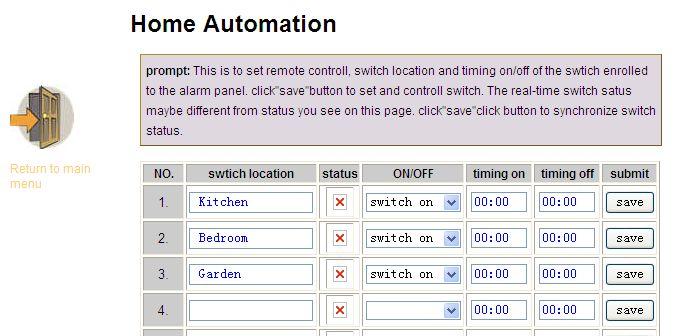

66 7.16 Home Automation It can set 16CH appliance switch. 60

67 Chapter VIII Mobile APP Management The alarm control panel support IOS&Andriod mobile remote control. APP NAME: SMART HOME EX Current state:includes [arm] [stay] [disarm] [clear], remote control the alarm control panel s alarm mode by the TCP/IP network. Module: includes[ zone bypass control] [switch control] [log events] [function settings] [Account information] [system settings] 8.1 Enter Into the App 61


68 8.1.1 Local Account First, create the local account Name: the name of the alarm control panel. User name: the admin user name of the alarm control panel. Password: the alarm control panel s admin password. IP address: the IP address of the alarm control panel. Port: 8000 is fixed for the mobile port. 62
69 Note: Before enter into the mobile app. User have to input the IP address and port configuration. For the local account, it have two ways to connection. 1. Wan -LAN(mobile is 3G/4G network. Alarm control panel is LAN network) * If need the WAN access to LAN network. Need to make the port mapping from the Router. WEB IE also similar operations Example: *IP address for the alarm control panel is *Router port mapping Mobile WAN PORT 8000 LAN PORT 8000 WEB IE WAN PORT 1027 LAN PORT 1027 * Set network gate way with similar segment to the IP address of the system * when you enter into the local account, the IP address should input the dynamic IP address. Not the alarm control panel IP address. In china, the dynamic IP address is changing every day. Here suggest customer to apply for a domain name and binding the dynamic IP address. Directly input the domain name here can enter into the app. 2. LAN-LAN(mobile and alarm control panel in a one LAN network) After setting the network IP address, gate, with similar segment and the mobile cellphone with similar LAN network to the alarm control panel. Directly input the IP address of the alarm control panel to enter the APP. 63
70 8.1.2 Platform Account Need the Meian software to control. Please contact sales person from our Meian company. 8.2 Zone Bypass Control When one of the zone faulty and can not enforce arm the system. Check the zone bypass list and can bypass the faulty zone. 8.3 Log Events inquiry the alarm control panel s alarm log events. 64


71 8.4 Function Settings. First enter into the function setting have to set the gesture password. 65

72 Includes: center platform, network, system setting, phone setting, wireless device, zone setting, RFID settings, alarm settings. GPRS settings, protection settings, settings, time settings. Function similar to WEB IE and alarm control panel setting. 66
73 Chapter VXI Technical Specification General information 1.Power supply: 15V/2000mA 2.Built in rechargeable battery:11.1v/1000mah 3.System static current: <50mA(exclude wireless detector) 4.System alarming current: <300mA(exclude wireless high siren current) 5.System maximum output current: 100mA(supply wireless detector) 6.Frequency:433MHz/868MHz 7.Signal transmit distance: 100 to 150 meters (open area) 8.The method of alarming dial: DTMF GSM or GPRS 9.Communication protocol with CMS: Ademco Contact ID 10.DTMF dial frequency variation:,1.5% 11.Recording time:15s Physical performance. Operation temperature range: 0-45 (32F-120F Storage temperature range: (-4F-140F) Relative humidity: 85% at 30 (86F) Color: as box indicated. 67
74 Chapter VXII Maintenance 10.1 Regular Test Design of components of the system is to reduce maintenance cost, but still it is suggested that periodical check may be carried out The Cleanliness of Control Main Machine Main control panel may be stained by fingers or covered by dust after using for a while. Use soft cotton cloth or sponge to clean it, don't use any lubricant, liquid such as kerosene, acetone and strong gel which will damage appearance and the transparency of top window. Attention: don't use any lubricant, liquid such as kerosene, acetone and strong gel which will damage appearance and the top transparency of window. Chapter VXIII Limitation of the Products. Although the products is a high standard products, there is also some limitation of them such as false alarm or no alarm. The reasons may be below: Lack of maintenance, the system needs maintenance and test regularly test the sensitive of the detector may decrease and the siren may not whistle. Lack of power supply if no power input and the back up power is not enough, the panel can not work normally. Telephone line false, if the telephone line is cut, the panel could not send alarm signals. Limitation of smoke detectors, if the smoke is far from the smoke detector, the detector could not alarm. If the intrude break in through some door or window not monitored. Or someone know how to make the system not work. 68


75 MEIAN PE DEMO P AND E ELECTRONICS HK LIMITED SHENZHEN MEIAN TECHNOLOGY CO., LTD No.32, Lanshui Rd, Meian Industrial Park, Longgang District, Shenzhen City, China. postal code: Phone: Fax: Demo Video :
System. For a better understanding of this product, please read this user manual thoroughly before using it.
 GSM Alarm System User s Manual For a better understanding of this product, please read this user manual thoroughly before using it. Chapter 1. Features Chapter 2. Control Panel Introduction Chapter 3.
GSM Alarm System. User s Manual. Profile. MOBILE CALL GSM Alarm System
 MOBILE CALL GSM Alarm System GSM Alarm System System disarmed 11/26/2013 User s Manual Profile For a better understanding of this product, please read this user manual thoroughly before using it. CONTENTS
Preface. Thank you for purchasing our GSM Security Alarm System ( The System )! The System will keep your home and property safe around the clock.
! The System will keep your home and property safe around the clock.") Preface Thank you for purchasing our GSM Security Alarm System ( The System )! The System will keep your home and property safe around the clock. The GSM Security Alarm ( The Alarm ) adopts the most advanced
Preface Thank you for purchasing our GSM Security Alarm System ( The System )! The System will keep your home and property safe around the clock. The GSM Security Alarm ( The Alarm ) adopts the most advanced
USER S MANUAL. Profile. MOBILE CALL GSM Alarm System
 MOBILE CALL GSM Alarm System USER S MANUAL System disarmed 00/00/00 00:00 ARM STAY CALL 1 2 3 4 5 6 7 8 9 Power Set Signal Alarm SOS ESC 0 ENTER Profile For a better understanding of this product, please
GSM RFID VOICE Alarm System
 GSM RFID VOICE Alarm System User s Manual For a better understanding of this product, please read this user manual thoroughly before using it. CONTENTS [Function Instruction] [Control Panel] Control Panel
Profile. For a better understanding of this product, please read this user manual thoroughly before using it.
 Intelligent GSM Auto-Dial Alarm System User s Manual Profile For a better understanding of this product, please read this user manual thoroughly before using it. Contents Function Introduction (3) Alarm
MOBILE CALL GSM Alarm System User s Manual
 MOBILE CALL GSM Alarm System User s Manual Profile For a better understanding of this product, please read this user manual thoroughly before using it. Contents Function Introduction (3) Alarm Host Diagram
Intelligent Wireless GSM Alarm System
 Intelligent Wireless GSM Alarm System 00M2K User s Manual Profile For a better understanding of this product, please read this user manual thoroughly before using it. Contents [Function Instruction] [Alarm
NEUTRON TCP/IP Alarm Control Panel Instruction Manual NTA-GNA8540
 NEUTRON TCP/IP Alarm Control Panel Instruction Manual NTA-GNA8540 Wiring diagramme LED dispaly Blink when GSM on metal box work normal Buzzer or speaker CMS connect(quick blink) disconnect(slow blink)
WiFi GSM APP Smart Home Security System
 User Manual WiFi GSM APP Smart Home Security System Tips: Please read through this user manual before installation so as to operate properly. Please keep well of the user manual for further reference.
To activate using remote control: press [ ] key once. To activate using keyboard: on panel keyboard [ ] keys once.
![To activate using remote control: press [ ] key once. To activate using keyboard: on panel keyboard [ ] keys once.](/thumbs/93/113878877.jpg "To activate using remote control: press [ ] key once. To activate using keyboard: on panel keyboard [ ] keys once.") Table of Content 1.1General Description----------------------------------------------------------------------2 2.2System Setup-----------------------------------------------------------------------------3
Table of Content 1.1General Description----------------------------------------------------------------------2 2.2System Setup-----------------------------------------------------------------------------3
V1.0. Smart Home Alarm System. User Manual. APP download via QR Code scanning. Please read the manual carefully before using.
 V1.0 Smart Home Alarm System User Manual APP download via QR Code scanning Please read the manual carefully before using. Content FUNCTION PROFILE 2 THE SCHEMATIC GRAPH OF HOST 3 PROCESS OF BOOTING 6 OPERATION
Wolf Guard Touch Keypad GSM Wireless alarm system User s Manual
 Wolf Guard Touch Keypad GSM Wireless alarm system User s Manual Page 1 Warning Do not remove the front or back cover of the unit and keep it intact. There are no parts inside this unit that can be repaired
D3D Wi-Fi GSM Smart Alarm System -User Manual
 D3D Wi-Fi GSM Smart Alarm System -User Manual D3D Wi-Fi / GSM Smart Alarm system (Model : D10). Please read all instructions carefully & follow steps for easy home installation. 1 P a g e D3D Wi-Fi / GSM
With Magictrl, you can control MatiGard anytime & anywhere via your smartphone, even without data network.
 MatiGard User Guide 02 Menu Feature-------------------------------------------------------------- 05 Overviews---------------------------------------------------------- 07 Read Before Using-----------------------------------------------
GSM Emergency Alarm. User s Manual. For a better understanding of this porduct,please read this user manual thoroughly before using it.
 Version: MS1 GSM Emergency Alarm User s Manual For a better understanding of this porduct,please read this user manual thoroughly before using it. CONTENTS CONTENTS Ⅰ. Introduction Ⅱ. Product Appearance
GSM Smart Home Alarm Apparatus. [99+4 defense zones] Instruction for Use
![GSM Smart Home Alarm Apparatus. [99+4 defense zones] Instruction for Use](/thumbs/83/87979951.jpg "GSM Smart Home Alarm Apparatus. [99+4 defense zones] Instruction for Use") GSM Smart Home Alarm Apparatus [99+4 defense zones] Instruction for Use Table of content Ⅰ. Introduction to the system... 2 Ⅱ. Introduction to function... 2 Ⅲ. System composition and use method... 3 Ⅳ.
GSM Smart Home Alarm Apparatus [99+4 defense zones] Instruction for Use Table of content Ⅰ. Introduction to the system... 2 Ⅱ. Introduction to function... 2 Ⅲ. System composition and use method... 3 Ⅳ.
S3 Sim Secual Alarm system with GSM transmitter
 S3 Sim Secual Alarm system with GSM transmitter www.etiger.com Features Control Panel Layout (Back) - ARM CPU + Auror CPU - GSM frequency: 850 / 900 / 1800 / 1900 MHz, suits all phones - Supports up to
13. The wireless coding and timing arm and disarm settings Function Setting First / second group of time arm set 1.
 Contents 10.4 Arm and disarm the Upload Settings Preface 11. Alarm type set Function Instruction 12. Zone type setting About the host 13. The wireless coding and timing arm and disarm settings Function
SK642 THE TELEPHONE DIALER REQUIRES A LAND TELEPHONE LINE TO MAKE OUTGOING CALLS AND ELECTRICITY.
 SK642 WIRELESS WATER ALARM SYSTEM WITH AUTO DIALER OWNER'S MANUAL AND SET UP INSTRUCTIONS. Thank you for choosing Ideal Security s Wireless Water Alarm with Telephone Dialer. Please read through complete
Contents. Glossary
 Contents Glossary ------------------------------------------------------------------------------------------------------ 6 1. Introduction to the IDS 1632 -------------------------------------------------------------
1. Introduction. 2. Product overview
 1. Introduction The AG400011 GSM Alarm panel is a control panel that is compatible with other H-net security devices from Everspring, such as wireless sensors, remote keyfobs, tags, and keypad. With this
Thank you for choosing Ideal Security s Home Security System with Telephone Dialer.
 SK618 WIRELESS ALARM SYSTEM WITH AUTO DIALER OWNER'S MANUAL Thank you for choosing Ideal Security s Home Security System with Telephone Dialer. If at any time during your installation you have any questions
Security GSM Alarm System
 Security GSM Alarm System USER MANUAL 4 wired and 6 wireless defense zones; Can preset and store 6 voice phones and 3 message phones; Remote two-way intercom; Telephone (mobile phone) remote control programming;
SMART HOME SECURITY. Dual Network Communicating Alarm System with RFID INVINCIBLE. Instruction Manual. Customer Helpline
 SMART HOME SECURITY Dual Network Communicating Alarm System with RFID INVINCIBLE Instruction Manual Customer Helpline 045 57 500 Table of Contents Kit Contents ---------------------------------------------------------------------
BURGLAR ALARM PANEL BS-468
 BURGLAR ALARM PANEL BS-468 Contents 1. Description... 3 2. Instructions for the user... 4 2.1Basic operations... 4 Complete system.... 4 Split system.... 4 2.2 Armed system indication... 5 2.3 Advanced
Control/Communicator Installation Manual
 DAS NETWORX NX-12 Control/Communicator Installation Manual General Description...2 Ordering Information...2 Option Definitions...3 Programming the LED Code Pads...5 Programming the NX-12...9 Types of Programming
PiSector GSM Cellular Wireless Alarm System
 PiSector GSM Cellular Wireless Alarm System User Manual ( GS08 ) Read manual fully before use. PiSector Inc., USA, www.pisector.com Welcome to PiSECTOR Thank you for choosing PiSECTOR. Everyone at PiSECTOR
WIRELESS ALARM SYSTEM WITH TELEPHONE AUTO DIALER
 BAT.LOW AC WIRELESS ALARM SYSTEM WITH TELEPHONE AUTO DIALER THE SYSTEM THAT CALLS YOU! Our WIRELESS ALARM SYSTEM WITH TELEPHONE AUTO DIALER is designed to allow you to create your own security system.
Vcare. User Manual. Ver WiFi - GSM- App. Smart Home Security System
 Vcare User Manual Ver.20161126 WiFi - GSM- App Smart Home Security System Tips:. Carefully read through this user manual prior to installation. Keep the user manual in a safe place for future reference
Touch Keypad GSM Smart Alarm System USER MANUAL
 Touch Keypad GSM Smart Alarm System USER MANUAL I. Foreword Thank you for purchasing and using GSM LCD touch screen wireless home alarm system. This is a Hi-tech household security product. It will make
Thank you for choosing Ideal Security s Home Security System with Telephone Dialer.
 SK618 WIRELESS ALARM SYSTEM WITH AUTO DIALER OWNER'S MANUAL Thank you for choosing Ideal Security s Home Security System with Telephone Dialer. If at any time during your installation you have any questions
Contents. Contents
 Contents Contents-----------------------------------------------------3 Preface-------------------------------------------------------------------4 Function Introduction-------------------------------------------------5
User Manual (LS-GSM-006)
") GSM Home/Business Alarm System User Manual (LS-GSM-006) Profile For a better understanding of this product, please read this user manual thoroughly before using it. - 1 - Catalogue: Function Introduction
GSM Home/Business Alarm System User Manual (LS-GSM-006) Profile For a better understanding of this product, please read this user manual thoroughly before using it. - 1 - Catalogue: Function Introduction
MG Partition 64-Zone Wireless Console with GPRS/GSM Version 1.6. Section Programming Guide
 MG6250 2-Partition 64-Zone Wireless Console with GPRS/GSM Version.6 Section Programming Guide Things You Need to Know About this Programming Guide The MG6250 All-in-one Wireless Console can be programmed
Content. Chapter 1 Knowing the alarm host 1.1 Features 1.2 Technical Parameters 1.3 Packing List 1.4 Knowing the alarm host
 Content Chapter 1 Knowing the alarm host 1.1 Features 1.2 Technical Parameters 1.3 Packing List 1.4 Knowing the alarm host Chapter 2 Alarm phone&sms number settings 2.1 Alarm phone setting. 2.2 SMS numbers
Version 1.03 January-2002 USER S MANUAL
 Version 1.03 January-2002 1 USER S MANUAL 2 Version 1.03 January-2002 System Details CUSTOMER:...... PHONE:... FAX:... INSTALLED BY:...... PHONE:... FAX:... MAINTENANCE & SERVICE:...... PHONE:... FAX:...
3 User s settings. 3.3 Internal clock setting
 2.9 Subsystem arming In a large building a sub control panel can be enrolled to the JA-63. The subsystem reports all alarms and failures to the main system. The installer can program if the systems will
Honeywell Control Panels FOR RESIDENTIAL AND COMMERCIAL INSTALLATIONS. Feature Charts
 Honeywell Control Panels FOR RESIDENTIAL AND COMMERCIAL INSTALLATIONS Feature Charts Control Panels FEATURE CHART LYNX Plus (L3000) (Supported Feature) (Not Supported) N/A (Not Applicable) LYNX Touch (L5210)
GSM LCD Touch Keypad Wireless Intelligent Alarm System. User s manual
 GSM LCD Touch Keypad Wireless Intelligent Alarm System User s manual I. Foreword Thank you for purchasing and using GSM LCD touch keypad wireless intelligent home alarm system. This is a high-performance
M2M Services Ltd. RControl Alarm - Installer Manual V 1.0
 M2M Services Ltd. RControl Alarm - Installer Manual V 1.0 Content Content... 2 Wiring the power supply module... 3 Wiring a siren... 3 SMARTEnroll self-learning zones... 3 Wireless keyfobs... 3 Supported
VAP304 PRO INSTALLATION & OPERATION MANUAL
 VAP304 PRO INSTALLATION & OPERATION MANUAL Panic Fire Duress Program Bypass Report Chime Test Memory B A D C Program Chime Panic Duress Exit Fire Report Bypass Memory Test Reset Password Exit Reset Password
Quick Installation Manual LED Touch Keypad Autodial Wireless Alarm System
 Quick Installation Manual LED Touch Keypad Autodial Wireless Alarm System By shield4u http:// (Version 20110816) A. Alarm Understanding Away Disarm Home Emergency Function Signal Interpretation Buzzer
AXI LED USER MANUAL (REV. 1.0)
") Security & Home Automation System AXI LED USER MANUAL (REV. 1.0) CONTENTS PREFACE FEATURES LED KEYPAD OUTLOOK 1.0 LIGHT INDICATION 1 2 4 6 CHAPTER 1: ALARM SYSTEM CONTROL 1.0 USING LED KEYPAD 1.0.1 ARMING
Security & Home Automation System AXI LED USER MANUAL (REV. 1.0) CONTENTS PREFACE FEATURES LED KEYPAD OUTLOOK 1.0 LIGHT INDICATION 1 2 4 6 CHAPTER 1: ALARM SYSTEM CONTROL 1.0 USING LED KEYPAD 1.0.1 ARMING
1. User features of the GSM dialer
 1. User features of the GSM dialer The JA60GSM dialer offers many useful features described in detail below. The installer should properly demonstrate the use of the system to the user after installation
S6 Titan Security System. Wi-Fi and 3G GSM
 S6 Titan Security System Wi-Fi and 3G GSM Version 1 - Apr 2018 Table of Contents Introduction 1 Self Monitoring 1 GSM SIM Card and Land Line 1 Free Mobile App (iphone / Android) 1 Pre-Programmed Accessories
User s Guide. SUB-MA7240O-0001.OG.Solution doc. Created: 6/05/03. Last Updated: 23/09/03. MA7240AO-0001 Version 1.0
 User s Guide SUB-MA7240O-0001.OG.Solution40-111.doc Created: 6/05/03 Last Updated: 23/09/03 MA7240AO-0001 Version 1.0 2 Table Of Contents User List...6 Quick Reference..7 Features...7 Keypad User's Guide...8
WiFi + PSTN. Smart Home Alarm System
 WiFi + PSTN Smart Home Alarm System Content Preface Specifications Technical information Front side panel view Back side panel view Initialization APP names Add alarm host and connect WiFi for host How
GSM-SMS-APP Smart Touch Alarm System
 SECURE YOUR HOME User Guide Ver.1810 GSM-SMS-APP Smart Touch Alarm System Dear users, Thanks for selecting the touch alarm system. Please read through this guide before installation so as to operate properly.
GSM CAR ALARM SYSTEM USER S MANUAL
 Features: GSM CAR ALARM SYSTEM USER S MANUAL 1 Mainframe size: 134MM*120MM*34MM 2 Mainframe: Working Voltage: 12V Static current: (including GSM module) 40mA-60mA Frequency: 300MHZ-350HMZ Cover range and
Advisor Advanced Mobile Application User Manual
 Advisor Advanced Mobile Application User Manual Content Warnings and Disclaimers 2 Advanced Mobile 2 Contact information 2 Description 2 Screen navigation 4 Gestures 4 Menu 4 Help navigation 4 Login 5
JA-63 Profi User manual
 JA-63 Profi User manual Contents: 1 Limited warranty... 2 2 Indicators... 3 3 Controlling the system... 4 3.1 Arming... 5 3.2 Disarming... 6 3.3 Panic Alarm... 6 3.4 To stop ALARM... 6 3.5 Home arming...
Remote switching machines with a SMS text from your mobile phone! Remote Monitoring your assets in the worldwide by your mobile Phone!
 Remote switching machines with a SMS text from your mobile phone! Remote Monitoring your assets in the worldwide by your mobile Phone! GSM SMS Controller DCS-130 User Manual Ver 1.20 Date Issued: 14-9-2010
Alarm Control Panel WIC-16Z4P WIC-5Z2P. User Instructions
 WIC-16Z4P WIC-5Z2P User Instructions Page : 2/14 INDEX # Function Page 1 Add a New User Code 11 2 Arm or Disarm All Areas or Disarm Selected Areas (Partitioned System) 8 3 Arming the System (Away Mode)
status AW1 WiFi Alarm System Printed in China PA : AW1-UM-EN-V1.0 User Manual 2016 Chuango. All Rights Reserved.
 status 2016 Chuango. All Rights Reserved. Printed in China PA : AW1-UM-EN-V1.0 AW1 WiFi Alarm System User Manual Foreword Contents Congratulations on your purchase of the AW1 Alarm system. Before you commence
Fire Command Keypad. XR5 User s Guide
 Fire Command Keypad XR5 User s Guide Silencing an Alarm While the fire alarm horns, strobes, or sirens are sounding use one of the following methods to silence the alarm depending on which type of keypad
SA 2650 Kit User Manual
 SA 2650 Kit User Manual Table of Contents 1. System Installation Planning 1 2. Device Introduction 3 3. Getting Started 6 4. System Default Setting 10 5. Connect2Home Application 11 6. System Information
DYGIZONE GJD910 Lighting Controller & Enunciator
 DYGIZONE GJD910 Lighting Controller & Enunciator MASTER WIRING IDENTIFICATION Power up to the DygiZone and you will see: All the LED s (red,yellow,green and blue buttons) will flash All the LCD icons will
Series. NX-4-EUR Control Panel. Installation manual
 g GE Security NetworX TM Series NX-4-EUR Control Panel Installation manual CONTENTS CONTENTS...2 GENERAL INFORMATION...4 ORDERING INFORMATION...4 FEATURE DEFINITIONS...5 PROGRAMMING THE NX-4 KEYPADS...12
Quick Reference Guide
 infinite Prime with Hybrid Connections User Manual - Version 1.00 Catalog Number: ZI0473A (1/07) All data is subject to change without prior notice. Hereby, Electronics Line 3000 Ltd. declares that this
A1UL PERS. Personal Emergency Response System. For Technical Support Please Contact Your Service Provider Or Distributor
 A1UL PERS Personal Emergency Response System TABLE OF CONTENTS 1. READ THIS FIRST... 1 2. SYSTEM OVERVIEW.. 1 3. COMPONENTS 2 4. UNIT OPERATION! Standby Mode.. 3! Emergency Activation. 3! Answering Incoming
2G & 3G GSM Portable PIR Alarm
 2G & 3G GSM Portable PIR Alarm www.gsm-activate.co.uk MODEL RF - PORTABLE-PIR PAGE 1 Product Information Our 2G/3G Portable PIR Alarm is a standalone alarm system suitable for indoors or outside usage.
DESCRIPTION OF KEYPAD (Access module with segments)
") DESCRIPTION OF KEYPAD (Access module with segments) For the most convenient control and status indication the JABLOTRON 100 system offers various types of access modules. Controlling (setting, unsetting
DESCRIPTION OF KEYPAD (Access module with segments) For the most convenient control and status indication the JABLOTRON 100 system offers various types of access modules. Controlling (setting, unsetting
GSM SMS Controller GSM SMS Alarm Unit S130 S140 S150. User Manual
 Remote switching machines with a SMS text from your mobile phone! Remote Monitoring your assets in the worldwide by your mobile Phone! GSM SMS Controller GSM SMS Alarm Unit S130 S140 S150 User Manual Ver
Watchguard WGAP864 User Manual
 Watchguard WGAP864 User Manual v1.0 Issued September 2016 1 2 Table of Contents Glossary... 5 1. Introduction to your Watchguard WGAP864... 6 2. Before Operating your Alarm System... 6 3. Understanding
2000 Series. Program Entry Guide. Control Panels
 2000 Series EN Program Entry Guide Control Panels 2000 Series Program Entry Guide About This Manual EN 2 About This Manual This guide describes the programming parameters available to the 2000 Series Control
Ontech GSM 9040/50. Reference Manual English -1 -
 Ontech GSM 9040/50 Reference Manual English -1 - Content Welcome... 5 This manual... 5 Text styles... 5 Support... 5 Disclaimer... 5 Overview... 6 Accessories... 6 External temperature sensor 9901... 7
Security Alarm Systems
 eclipse Security Alarm Systems Contents Introduction 2 System Configuration 3 Control Panels 4 Remote Keypads & Expanders 5 Communication Modules 6 Upload/Download 6 Specifications 7 Introduction Zeta
 www.eraeverywhere.com ERA Home Security Straight Road, Short Heath, Willenhall, West Midlands, WV12 5RA email: alarms @ eraeverywhere.com Customer Helpline: 0345 257 2500 Vault_V1.0_3616 IMPORTANT Table
Ref. 1067/024 Ref. 1067/032A Ref. 1067/052A
 DS1067-062C Mod. 1067 LBT20063 REMOTE CONTROLLABLE ALARM CONTROL PANELS Ref. 1067/024 Ref. 1067/032A Ref. 1067/052A USER MANUAL TABLE OF CONTENTS INTRODUCTION... 6 1 CONTROL DEVICES... 7 1.1 1067/022 keypad
EC-P Zone Intruder Alarm System
 EC-P10 10-20 Zone Intruder Alarm System Installation Manual Contents 1. System Overview... 4 System Configuration... 4 Control Panel... 5 Remote Keypads... 5 EC-LED Remote Keypad... 5 EC-LCD Remote Keypad...
2G & 3G GSM Door Contact Alarm
 2G & 3G GSM Door Contact Alarm www.gsm-activate.co.uk MODEL RF - PIR PAGE 1 Product Information Our 2G/3G GSM Door Contact Alarm is a standalone alarm system for smaller rooms inside properties. It will
Alarm Control Panel WIC-16Z4P WIC-5Z2P. Installation & Operation User Manual
 WIC-16Z4P WIC-5Z2P Installation & Operation User Manual Page : 1/34 INDEX # Function Page 1 Abort Current Communication and Clear Reporting Queue (*59) 13 2 Abort Current Communications (*59) 10 3 Account
SCORPION Z16040C, Z8040C and Z5120C
 SCORPION Z16040C, Z8040C and Z5120C Alarm Controller User Instructions Thank you for choosing to purchase this micron security alarm controller. Micron product is manufactured to exacting quality standards.
Other trade names mentioned in this document may be registered trademarks or trademarks of respective product manufacturers or vendor products.
 Attention! Read this user manual carefully. Representative of the company installing the alarm system will explain which security module SP231 functions needs to be activated to ensure proper security
reading carefully this guide, operating this system strictly on the standard procedure. System 816
 Thanks for choosing System 816 Multi-Function Alarm Control Panel. We suggest you reading carefully this guide, operating this system strictly on the standard procedure. System 816 is suitable for most
reading carefully this guide, operating this system strictly on the standard procedure.
 SYSTEM-ZDAS-16CA-8 PROGRAMMING GUIDE Thanks for choosing ZDAS-16CA-8 Multi-Function Alarm Control Panel. We suggest you reading carefully this guide, operating this system strictly on the standard procedure.
READY TO ARM 1st Floor 2nd Floor
 SECOLINK KM24, KM24A, and KM24G are user-friendly new concept keypads. Large graphic display with helpful texts and backlit keys simplify the use of an alarm system. There are options to customize main
QUICK USER MANUAL. Alarm Control Panel. The full user manual and other manuals are available on
 Alarm Control Panel Firmware Version 1.09 QUICK USER MANUAL The full user manual and other manuals are available on www.satel.eu versa_ip_us_en 11/17 SATEL sp. z o.o. ul. Budowlanych 66 80-298 Gdańsk POLAND
MT-S20 USER S MANUAL. (Motor Alarm &Tracker) (Version 1.4)
 (Version 1.4)") MT-S20 USER S MANUAL (Motor Alarm &Tracker) (Version 1.4) IndeX Chapter 1 Introduction 3 1. Package Contents... 5 2. Features & Specification:... 6 2.1 Main Features:... 6 2.2 Specifications:... 6 3. Application
MT-S20 USER S MANUAL (Motor Alarm &Tracker) (Version 1.4) IndeX Chapter 1 Introduction 3 1. Package Contents... 5 2. Features & Specification:... 6 2.1 Main Features:... 6 2.2 Specifications:... 6 3. Application
PWM. Solar Charge controller with Ethernet. Solar Smart PWM 20Amp. Hardware Description : Release : 19 June 2014
 Solar Charge controller with Ethernet Release : 19 June 2014 Hardware Version : Version 1 Firmware version 1 PC Application Software : Version 1.0.0.0 Hardware Description : The Solar Smart regulator was
NetworX Series. NX-8 Commercial Fire Panel Installation and Startup
 NetworX Series NX-8 Commercial Fire Panel Installation and Startup 2004 GE Security All rights reserved. Printed in the United States of America. These instructions do not purport to cover all details
DSC PowerSeries NEO Quick Start Guide
 DSC PowerSeries NEO Quick Start Guide WE DO NOT RECOMMEND BEING IN ANY PROGRAMMING SECTION THAT IS NOT IN THIS GUIDE UNLESS YOU FULLY UNDERSTAND THE FUNCTION OF THAT SECTION. Doing so may cause problems
ALARM SYSTEM USER S MANUAL Rev
 ALARM SYSTEM USER S MANUAL Rev.06 890-00011 Manufacturer: Viatron Electronics 3514 1st Street, St-Hubert (Quebec) Canada J3Y 8Y5 WARNINGS the warranty can be void if the Agri-Alert 2400 is used in a manner
Memcom Emergency Telephone
 Memcom Emergency Telephone Installation Guide Ref No. 450 900 (GB) Version 2 + + Simple wiring for quick installation + + Integrated LCD display shows you what you have programmed + + All code based programming
Elite 16D Version 16 Zone Controller Arrowhead Alarm Products Ltd. Operating Guide. Proudly Designed and Manufactured in New Zealand
 6 Elite 16D Version 16 Zone Controller Arrowhead Alarm Products Ltd Operating Guide 1 Proudly Designed and Manufactured in New Zealand CONTENTS Page No. INTRODUCTION 3 About your Alarm 3 OPERATING YOUR
CONTENTS. (User s Manual)
") CONTENTS (User s Manual) 1. Foreword & Main Features & Brief introduction of the Product 2. Understanding of Alarm Host 3. Specifications 4. Type and definition of Defense Line 5. Programming the alarm
CONTENTS (User s Manual) 1. Foreword & Main Features & Brief introduction of the Product 2. Understanding of Alarm Host 3. Specifications 4. Type and definition of Defense Line 5. Programming the alarm
BURGLAR ALARM PANEL BS-468/A
 BURGLAR ALARM PANEL BS-468/A Contents 1. Description... 4 2. User instructions... 5 2.1. Basic operations... 5 Complete System... 5 Split System... 5 2.2. Armed system indication... 6 2.3. Advanced operations...
Lyric Gateway. User Reference Guide. Ref: LCP300-L/LCP300-LC /16 Rev A
 Lyric Gateway User Reference Guide Ref: LCP300-L/LCP300-LC 800-21670 10/16 Rev A Your Honeywell security system is designed for use with devices manufactured or approved by Honeywell for use with your
Elderly Care Alarm System
 Introduction 24/7 Peace of mind for your family The GSM Elderly Care Alarm System is a new released smart solution for take care of senior, aged, elder or disabled people on their daily life. Big LED display
MG5000 V2.4 MG5050 V2.4 SP5500 V2.4 SP6000 V2.4 SP7000 V2.4. Programming Guide
 MG5000 V2.4 MG5050 V2.4 SP5500 V2.4 SP6000 V2.4 SP7000 V2.4 Programming Guide We hope this product performs to your complete satisfaction. Should you have any questions or comments, please visit www.paradox.com
EM8710 GSM Alarm System Starter Kit
 EM8710 GSM Alarm System Starter Kit EM8710 - GSM Alarm System Starter Kit 2 ENGLISH Table of contents 1.0 Introduction... 3 1.1 Packing contents... 4 2.0 Explanation of the Alarm system... 5 2.1 Front...
Instructions manual. By-alarm. By-alarm Manager software
 Instructions manual By-alarm By-alarm Manager software Index 1. Procedure for the complete programming of the By-alarm system 5 Operations to be carried out prior to the programming with By-Alarm Manager
TT16 RFID COLOR SCREEN INTELLIGENT GSM NETWORK ALARM SYSTEM. MODEL: KR-G19 BRAND: KERUI Secrui Electronic Co., Ltd
 TT16 RFID COLOR SCREEN INTELLIGENT GSM NETWORK ALARM SYSTEM 4px, Unit 5, Trident Way UB25LF Southall UNITED KINGDOM CONTACT: 02081278528 MODEL: KR-G19 BRAND: KERUI Secrui Electronic Co., Ltd Standards
Wireless Keypads LKP(E)S8M Series
S8M Series") Wireless Keypads LKP(E)S8M Series User manual Contents Congratulations on your purchase of this Honeywell wireless keypad. To make the best out of your equipment we advise you to read this manual carefully.
Wireless Keypads LKP(E)S8M Series User manual Contents Congratulations on your purchase of this Honeywell wireless keypad. To make the best out of your equipment we advise you to read this manual carefully.
LYNX Touch L5210 Series Security System
 LYNX Touch L5210 Series Security System User Guide 800-19975 12/14 Rev. B LYNX Touch L5210 Series Your Honeywell security system is designed for use with devices manufactured or approved by Honeywell for
Operation Manual Fighter ProVision Software. Version: 0.0 Revision: 1
 Operation Manual Fighter ProVision Software Version: 0.0 Revision: 1 TABLE OF CONTENTS 1. Introduction 5 2. Software Installation 5 3. PC Users 6 3.1 Introduction 6 3.2 Default Code 6 3.3 Edit PC User
i on Compact Security System
 i on Compact Security System Administration and User Manual Issue 1 Control unit software version 5.03 Eaton 2017 The information, recommendations, descriptions and safety notations in this document are
Using Your. Security System With LED Keypad S5030, S5031, S5032
 Using Your Security System With LED Keypad S5030, S5031, S5032 Contents 1 Overview Your Security System... 1 How Your Security System Works... 2 Your System's Programming... 3 Getting Used to Your System...
2G & 3G GSM Wireless Beam Alarm
 2G & 3G GSM Wireless Beam Alarm www.gsm-activate.co.uk MODEL RF - BEAM PAGE 1 Product Information Our 2G/3G GSM Wireless Beam Alarm is a standalone alarm system suitable for indoor and outside use. It