Installation Manual for D1100 / D1101 DigiCom
|
|
|
- Bethanie Ashlyn Miles
- 5 years ago
- Views:
Transcription
1 Installation Manual for D1100 / D1101 DigiCom Dycon Ltd Tel: +44 (0) Fax: +44 (0) Cwm Cynon Business Park Mountain Ash CF45 4ER - UK sales.en@dyconsecurity.eu
2 TABLE OF CONTENTS Index 2 Description 3 Part numbers 3 What to do: Installation 5 System testing 6 Troubleshooting 7 Helpdesk 8 The details: Inputs and self learning 9 Telephone line connection 10 Analogue PSTN telephone line connection 11 PABX connections 13 ISDN, ISDN2, ISDN2e 14 Home highway, business highway 15 ISDN30 16 ADSL and Broadband 17 The Call Minder call answering service 19 Safety earth connection 19 System power supply and battery 19 NVM programming, line monitoring 20 Appendix 1 LED indications 22 Appendix 2 Input connections 24 Appendix 3 Plug-on details 27 Appendix 4 Specification 29 Appendix 5 Approvals 30 Appendix 6 Glossary of terms 31 2
3 DigiCom Installation Manual Description DigiCom is an advanced auto-dialling digital communicator for alarm reporting. It can transmit alarm signals to an Alarm Receiving Centre via the analogue PSTN (Public Switched Telephone Network) using the DTMF Fast Format protocol. DigiCom has 8 alarm inputs. When triggered by the alarm system, it initiates calls to the Alarm Receiving Centre (ARC). DigiCom monitors the PSTN line continuously. If a fault occurs local annunciation is made. DigiCom comes complete with the Alarm Abort feature to enable older alarm systems to comply with the ACPO false alarm policy (in the UK). Once the system is set, if a misoperation occurs and the system is unset within 90 seconds, a Restore on Channel 3 or separate code will be sent to the Alarm Receiving Centre. If programmed a Tellback will also reset the control panel. DigiCom is available in two versions: stand alone and plug-on. DigiCom is housed in an ABS plastic case which protects the electronics and meets the PSTN safety requirements. A tamper protected steel box with an integral 1 amp power supply is also available. See below for part numbers. An NVM Programmer is available that connects to a PC computer. Part numbers D1100 D1101 D1055 D1154 D1500 D0730 D0402 DigiCom stand-alone DigiCom plug-on Box of 10 NVM ICs NVM programmer and software Tamper protected box with 1 amp power supply Security ADSL (broadband) filter Dycon products CD with manuals for all products 3
4 4
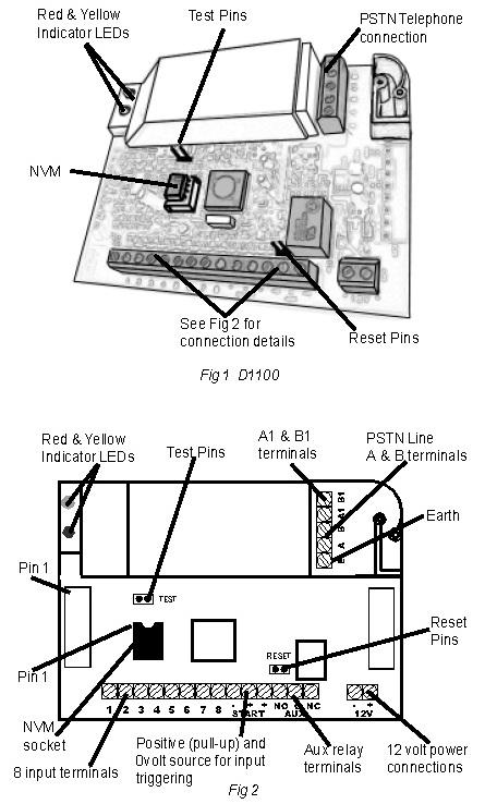
5 Installation Programme the NVM for the system specific requirements, or obtain a programmed NVM from your Alarm Receiving Centre. See page Totally power down the control panel mains and battery. 2. Fit the (programmed) NVM into the 8-pin socket located at the front of the DigiCom module ensuring correct orientation. See Fig 1and 2. The NVM should be programmed with the D1154 NVM programmer or any other proprietary programmer. A Master NVM may be required for some programmers. 3. If you are installing a D1101 plug-on DigiCom, plug the unit onto the control panel pins ensuring they are correctly aligned. 4. If you are you are using a D1100 stand-alone DigiCom, connect the input triggers as required. See Fig 1 and 2 and Self Learning Inputs on page On the stand-alone version, one changeover relay output is provided. See page 20. The connections marked Aux C, N.O and N.C can be programmed to operate: a) When a line fault is detected b) If a communication attempt fails c) If a communication attempt is successful d) When a communication attempt is in progress. 6. Connect the PSTN line to the terminals provided under the protective cover. See pages 11 to Connect the 12 volt supply to the 12v + & 12v - terminals. See Fig 1 and 2 and page Reconnect the mains supply to the control panel. 9. Your DigiCom is now ready for testing. 5
6 System Testing Ensure you have informed your Alarm Receiving Centre that you are ready to test your DigiCom Product. Note: If the NVM is faulty, fitted incorrectly or has been incorrectly programmed, the red and yellow communication LEDs will flash alternately. If there is a problem with the PSTN telephone line, the red communication LEDs will flash. See Appendix Power up the DigiCom, the unit will initialise. 2. Start testing by momentarily shorting the test pins on the DigiCom. This will cause DigiCom to send a test signal to the Alarm Receiving Centre. Once the test pins are shorted, the Active LED will illuminate. During communication the LED will flash to indicate the progress of the call, see Appendix 1. When DigiCom successfully communicates with the Alarm Receiving Centre, the Active LED will go off, this will mean that the test call is complete. 3. Now trigger all the used inputs on the DigiCom. This should be done by setting the control panel and triggering an alarm condition. If PA or fire circuits are being monitored, these should also be triggered. 4. Contact your Alarm Receiving Centre to confirm that all signals have been received. Ensure that all Restore signals are received when the DigiCom input terminals return to their quiescent value. 5. If the quiescent (non-active) states of the input terminals are incorrect, i.e. positive applied/removed is inverted, then the ARC will report that the alarm/restore or open/close is the wrong way round. To correct this, use the self learning input feature. See page If at any time you wish to cancel a call, short the reset pins. See Fig 1 and If you are using the Alarm Abort feature, set the alarm panel, initiate an alarm condition and (if the alarm system incorporates bell delay this will be overridden), unset the system within 90 seconds. Check that the alarm abort signal has been sent to the Alarm Receiving Centre and, if selected the alarm system has reset. 8. Your DigiCom is now fully tested. 6
7 Troubleshooting Q. What if there appears to be random triggering of the DigiCom? Ensure that 0 volts is common across all parts of the alarm system. If the DigiCom receives its power from a power supply that is additional to the alarm system, ensure that the 0 volt connection on the additional power supply is connected to the 0 volt connection on the alarm system. Check that the supply voltage is sufficient for reliable operation. A supply voltage below 9v will damage the standby battery and may generate spurious signals. Q. What if the Digital Communicator is not received by the Alarm Receiving Centre? Check that the NVM is fitted and has been correctly programmed, i.e. correct telephone numbers. Check that the PSTN line is properly connected. Check with a meter that approximately 50 volts DC is present across the PSTN terminals marked A and B. Connect a telephone to the PSTN line and make a call to ensure that it is fully functional. Remove telephone after test. Disconnect any other equipment that is using the same PSTN line to ensure that it is not inhibiting the DigiCom. Check that when the digital communicator is triggered, the voltage across the A and B terminals drops to between 6 and 12 volts DC. Ensure that call barring to the ARC Receiver telephone number has not been set on the PSTN line used by Digicom. See Appendix 1 for line monitoring indications. These will help diagnose line problems. Q. What if some channels are not received correctly by the Alarm Receiving Centre? Check that the NVM has been correctly programmed for your requirements. Repeat the Learning the Inputs programming stage. 7
8 Help Desk If you have installed the DigiCom in accordance with these instructions, checked all the above points but are still experiencing problems you can contact your DigiCom supplier or your Telecom Service Provider. In UK, DigiCom installation, programming, operation or other questions may be addressed to: Dycon Technical Support: Tel: +44 (0) The Dycon web site: contains the latest copies of all manuals for all Dycon products. Please ensure that you are working from the latest version. You can also download associated information and software samplers. Sales, shipping and contact information is here too. A CD is available that contains manuals for all Dycon products and the programming software for DigiCom and Dualcom. Contact our Technical Support for more information. 8
9 Inputs and Self Learning For full Inputs connection information see Appendix 2. To aid installation, DigiCom can learn the quiescent state of its inputs, i.e. the not active state, without having to re-program the NVM. This allows the unit to be programmed during installation with positive applied or positive removed inputs. It will correct NVMs that have been supplied with incorrect input polarities. 1. Setup the inputs non-active conditions by connecting a positive voltage or no voltage (0v) on each input terminal as required. This is easily achieved by connecting the control panel outputs to the DigiCom inputs, then put the control panel in the day state with no activated detectors and all alarm conditions reset. You can leave any unused DigiCom inputs disconnected. Non-active means that the voltage on the alarm inputs are in the not in alarm condition and open/close inputs are in the open, unset or day condition. 2. Ensure that the unset/open/day state is selected on the control panel, not the set or engineering states. 3. With the DigiCom powered up, apply a permanent short to the test pins with a jumper link or screwdriver blade etc 4. Momentarily short the reset pins. The red and yellow LEDs will flash: 4 red... 4 yellow... 4 red... etc indicating learning mode. 5. Remove the short on the test pins. The LED flashing will cease and the state of the 8 inputs will be remembered as the non-active condition. This information will be stored in the NVM. When complete, DO NOT park the jumper link onto BOTH test pins because this will immediately trigger a test call and inhibit further operation. 9
10 Telephone Line Connection There are several different types of telephone line available from different service providers. DigiCom, Dualcom, the Dycon range of control panels and most other intruder alarm equipment require an analogue telephone line connection. Earth Loop Calling or Earth Calling types of analogue telephone line cannot be used. Equipment that requires an analogue line cannot be connected directly to digital ISDN or digital or hybrid ADSL telephone lines. Details of these lines and connections follow. Analogue PSTN Telephone Line The analogue PSTN is a communication network where the line from the exchange equipment and the service supplied to the subscriber is analogue, i.e. not digital. See Fig 3. A telephone line is always terminated at the user s premises by an NTP (Network Termination Point) which is provided by the Telecomms Service Provider. This is a socket or connection where the user s equipment can be connected. Some NTPs provide a socket and terminals for connection. In many cases, the NTP operates using power supplied from the exchange equipment via the telephone line. An analogue PSTN telephone line may be provided by the telecomms service providers. DigiCom can be connected here. See Fig 3. Refer also to the Safety Earth and the Call Minder sections. 10
11 PSTN Line Connection Options DigiCom s line connection requires an analogue telephone line. Where the analogue telephone line also carries ADSL (Broadband) signals refer to ADSL later in this section. Connecting other telecomms equipment IN PARALLEL to the analogue telephone line used by DigiCom (or any digital communicator) can stop the unit sending alarm calls to an Alarm Receiving Centre. Parallel connection is NOT recommended for DigiCom when it is used in a security system. There are several ways that a DigiCom may be connected to a PSTN telephone line, particularly when other equipment needs to share the same telephone line. Some require that your Telecom Service Provider supplies particular line features. Some require NVM programming options. Refer also to the safety Earth and the Call Minder sections. The highest security PSTN line for DigiCom (Recommended): A PSTN line supplied as outgoing calls only, i.e. Incoming Ringing Barred, and the PSTN line is ex-directory, and the PSTN line goes to the DigiCom only. Other equipment can be connected to the DigiCom A1 & B1 terminals (i.e. series connection) to make outgoing calls only. See next page. The next best security option for a PSTN line (Recommended): A PSTN line supplied with the 3-way calling feature, and the DigiCom NVM is programmed for 3-way calling, and the PSTN line goes to the DigiCom only. Other equipment can be connected to the DigiCom A1 and B1 terminals (i.e. series connection) for incoming and outgoing calls. See next page. The no security option (NOT recommended!!!): A PSTN line supplied without outgoing calls only or the 3-way calling feature. This option cannot cancel or hold incoming calls and these will inhibit DigiCom from making a telephone call to the Alarm Receiving Centre. The parallel connection option (NOT recommended!!!): The DigiCom A and B terminals connect to the telephone line, and other equipment connects directly to the same telephone line. This connection option cannot cancel or hold incoming or outgoing calls and these will inhibit DigiCom from making a telephone call to the Alarm Receiving Centre. 11
12 PSTN Line Connection (DigiCom alone on line) Your Telecom Service Provider should be asked to supply and fit an analogue line and an NTP with terminals near the alarm system. The alarm installer should then follow steps 1, 2 and 4 below. See Fig 4. Note : If DigiCom is connected to the PSTN line and a telephone or other equipment is sharing the same line (parallel connection), the bell in the telephone may tinkle when DigiCom is operating. DigiCom alarm calls to the Alarm Receiving Centre will also be inhibited. See previous page. Series Connection (DigiCom and other equipment on line) Your Telecom Service Provider should be asked to supply and fit an analogue line and an NTP with terminals near the alarm system. The alarm installer should then follow steps 1-4 below. See Fig Use cable type 1/0.5mm CW1308, feed through the cable entry, connect the cores to the DigiCom terminals marked A and B. 2. Connect the other end of the cable to the terminal bock connections for the incoming telephone line, marked A and B, or 2 and If the PSTN line used by DigiCom is shared with other apparatus (e.g. telephone, fax or answer machine), connect the terminals marked A1 and B1 on the DigiCom to a PSTN Socket. (Terminals 1 and 6 in the NTP can be used as loop in points for this purpose). The customer may then plug their phone, fax etc into that socket. 4. On DigiCom and other equipment with an earth or E terminal, connect a 1.0mm earth cable to terminal E. Ensure that the other end of this earth cable is connected to a good ground earth. This protects the equipment from high voltages, e.g. lightning, that may strike the telephone line. Refer also to the safety Earth section. 12
13 PABX (Private Automatic Branch Exchange) A PABX is a telephone exchange in one business or building (where a dial 9 is needed for an outside line). It connects to one or more outside telephone lines and has two or more extensions within the business or building. See Fig 6. DigiCom may be connected to one of the outside telephone lines where they are the analogue PSTN type. DigiCom cannot be directly connected to a digital telephone line. See Fig 6. The extensions within the building may be analogue or digital. Where an extension is analogue, a normal phone or fax machine may be connected. DigiCom can be connected here and programmed to dial a 9. See Fig 7. Where the extension is digital, it is often to the ISDN standard or is a special digital standard that is particular to the manufacturer of the PABX equipment. Where a special digital standard is used, a special feature phone is usually required, provided by the manufacturer of the PABX equipment. DigiCom cannot be directly connected to any type of digital telephone line. Refer also to the safety Earth and the Call Minder sections. 13
14 ISDN (Integrated System Digital Network) The digital ISDN is a communication network where the line from the exchange equipment and the service supplied to the subscriber is digital, i.e. not analogue. An ISDN line is a digital telephone line that conforms to the international ISDN standard. It can carry several calls simultaneously. A basic rate ISDN telephone line can carry the equivalent of two simultaneous calls. In UK, a basic rate ISDN line is called ISDN2 or ISDN2e. A primary rate ISDN line can carry the equivalent of up to thirty simultaneous calls. In UK, a primary rate ISDN line is called ISDN30. An ISDN line is always terminated at the users premises by an NTP (Network Termination Point) which is provided by the Telecomms Service Provider. The NTP is a socket or connection where the users equipment can be connected. The service supplied to the user from the NTP may vary. The digital connection on the NTP is called the S-Bus. The S-Bus allows many different types of digital communication equipment to be connected, e.g. an ISDN interface card in a PC. In many cases, the ISDN NTP operates using power supplied from the exchange equipment via the ISDN telephone line, however some types of NTP may require a connection to the mains supply at the users premises. Some ISDN NTPs include a converter to provide analogue sockets (e.g. Home Highway). See page

15 ISDN2e (Integrated System Digital Network, 2 channel) A basic rate ISDN telephone line can carry the equivalent of two simultaneous calls. In the UK, a basic rate ISDN line is called ISDN2 or ISDN2e. Some suppliers call an ISDN2e line Home Highway or Business Highway. See below. Where an ISDN2 line is fitted but an analogue line is required, e.g. for DigiCom, then the D0700 ISDN-Analogue converter may be used. The D0700 has some important features, especially for security communications including over-ride line grab. Refer to the D0700 manual and see Fig 8. DigiCom cannot be directly connected to a digital telephone line. An ISDN2 line can be provided as point-to-point or point-to-multipoint. Where there is only one item connected to the S-bus then a point-to-point service is OK. Where two or more items are connected to the S-bus then a point-to-multipoint line must be provided. Home Highway, Business Highway Home Highway or Business Highway is the marketing name for a basic rate ISDN2 line supplied by BT with an NTE9 NTP. The NTE9 NTP provides two S-Bus sockets and it includes an ISDN-Analogue converter and two analogue telephone sockets. This type of NTP can have an analogue telephone, fax, modem etc connected at either or both of the analogue telephone sockets. DigiCom may be connected to these analogue sockets. See Fig 9. Power for the NTE9 comes from the exchange equipment via the ISDN line and also from the mains supply at the user s premises. 15
16 Home Highway, Business Highway (continued) In the event of mains failure, the right-hand analogue telephone socket on the NTE9 will cease to operate but all other functions are powered from the exchange equipment. It is important therefore to connect DigiCom to the left-hand analogue telephone socket on the NTE9. See Fig 9. A maximum of two calls on an NTE9 may be in progress at the same time. Use of one analogue telephone socket constitutes one call. Use of the S-bus on either S-bus socket constitutes one or two calls (64 or 128 K byte bandwidth). If two calls are in progress it is impossible to make another outgoing call or receive another incoming call. Refer also to the safety Earth and the Call Minder sections. The two call maximum means that if either of the S-bus sockets are being used and a telephone call is in progress on one analogue socket, then anybody ringing into the other analogue telephone socket will get a busy signal. Equally any connection to the other analogue socket, e.g. DigiCom or a telephone at the user s premises, will not hear the dialling tone and will not be able to dial out. Note that an override line grab facility does not exist on an NTE9. ISDN30 (Integrated System Digital Network, 30 channel) A primary rate ISDN line can carry the equivalent of up to thirty simultaneous calls. In the UK, a primary rate ISDN line is called ISDN30. This is a digital telephone line that conforms to the international ISDN standard. It can carry up to 30 simultaneous telephone calls. This type of digital telephone line normally connects directly to a PABX telephone exchange. See Fig 7. DigiCom cannot be directly connected to a digital telephone line. 16
17 ADSL (Asynchronous Digital Subscriber Line) or Broadband When an analogue PSTN telephone line also carries ADSL (Broadband) signals and it is used by a security system, e.g. Dualcom, then a security ADSL filter MUST be used. A filter is used to separate the analogue telephone signals from the ADSL (Broadband) digital data signals because the telephone or security system may be disrupted or completely inhibited if ADSL (Broadband) digital data is allowed into them from the telephone line. The D0730 security ADSL filter is designed specifically for use with security systems. It includes spare terminals to aid wiring that are labelled Pass Through. This item meets all of the requirements of the British and European telephone and security standards. See Fig 10. Other types of filter and plug-in filters should not be used for series connection of a security system to the telephone line. These types are for use with telephones, fax machines etc... Plug-in filters are available from the Telephone Service Provider and many electrical distributors including: CPC Part Number: TE or TE04070 Farnell Part Number: or Maplin Part Number: A61AK or A72AG Serial connection to a PSTN (and Broadband) telephone line is shown in Fig 11. The installer must ensure that: Fig 10 D0730 ADSL security filter 1. The user s telephone wiring is disconnected from the NTP and reconnected to the D0730 ADSL filter only. 2. The NTP connects only to the D0730 ADSL filter and to no other wiring or telephone sockets. 3. The wiring between the NTP and the D0730 ADSL filter cannot be unplugged by the user. 4. The user cannot plug a phone/fax etc into the NTP. 5. The terminals 2, 3 and 5, A and B and A1 and B1 are connected exactly as shown. 17
18 ADSL (Asynchronous Digital Subscriber Line) or Broadband Q. Why is a Broadband Filter necessary? A. When ADSL (Broadband) digital data is supplied on a normal PSTN telephone line then... an ADSL (Broadband) Filter must be fitted between that telephone line and each item of non digital equipment because the operation of non digital equipment may be disrupted or completely inhibited if ADSL (Broadband) digital data is allowed into it from the telephone line. Non digital equipment means anything that would be used on a normal analogue PSTN telephone line, i.e. a telehone, Fax machine, Dualcom, Digicom, digital communicator, control panel s Digi-Modem. 18
19 The Call Minder Call Answering Service Some Telecom Service Providers offer a call answering service. This will answer incoming calls if the subscriber s telephone is not answered within a number of rings. DigiCom NVM programming may need changing to ensure operation when this service is provided. This service is available from BT in most areas of the UK on analogue PSTN, ISDN, Home Highway and hybrid ADSL lines. It may also be available from other Telecomm Service Providers. DigiCom may be connected to lines offering this service. See earlier connection information. This service indicates to the subscriber that an earlier call has been recorded and should be heard by pulsing the dial-tone on subsequent calls. See the table below. Dial Tone Dialing Answered calls Continuous You may dial There are no answered calls Pulsed You may dial There are answered calls waiting to be heard The DigiCom NVM is normally programmed to require a dial-tone of 1 second before it will dial the number of the ARC to send its alarm information. When the dial-tone is pulsed as described above, the NVM programming must be changed to 0.1 second dial-tone detection to ensure correct operation. Safety Earth connection Some equipment requires an earth connection to meet the safety requirement of testing and approval. Other equipment designs provide electrical safety with no earth connection. Where an E or earth connection is provided at the telephone line terminals of equipment, then this must be connected to an earth point. DigiCom is this type. See Fig 1 and 2. Ideally, the earth point should be an earth stake in the ground, close to the equipment. Where this is unavailable, then a connection to the mains supply earth should be used. System Power Supply and Battery DigiCom requires a supply of volts DC at 20mA in standby and 75mA when activated. The installer must ensure that the alarm system power supply is rated to provide adequate power for this apparatus and for any other auxiliary apparatus drawing power from the alarm system power supply. If the supply voltage falls to below 11v, a Low Voltage signal will be transmitted to the ARC. If the standby battery voltage falls below 9v (deep discharge), the battery will result in permanent damage, and the reliable operation of the DigiCom is unlikely. If the DigiCom receives its power from a power supply that is additional to the alarm system, ensure that the 0 volt connection on the additional power supply is connected to the 0 volt connection on the alarm system. Only power supplies conforming to EN60950, EN41003 or International Safety Standards should be used with this apparatus. 19
20 NVM Programming The operating parameters for DigiCom, e.g. telephone numbers, are stored in the NVM (Non Volatile Memory). DigiCom is designed to use an NVM that has been specifically programmed for it, or an NVM that has been programmed for a Scantronic 8400, 8440 or 9056 Digital Communicator. Note: when using a Scantronic NVM, the option to specify regular dial-tone tests nor the ACPO Abort features will be available. The NVM can be programmed using the D1154 NVM programmer connected to a PC. The NVM can also be programmed by a Scantronic- type 7200 or 7300 programmer. Your Alarm Receiving Centre will normally provide a programming service and will supply programmed NVMs on request. Professional installers may also have the D1154 and be able to provide a DigiCom programming service. For a full list of programmable features see instructions for the D1154 NVM programmer. Calling a) DTMF or Pulse Dialling b) Three Way Calling (Select Services) c) Two telephone numbers for PSTN alarm reporting. Select Services If the PSTN line for the DigiCom is not outgoing calls only, we recommend that your Telecom Service Provider s Three Way Calling service (if available) is enabled on the phone line. The NVM will need to be programmed with 3-way calling enabled. This will ensure that DigiCom can make an outgoing PSTN call if the line is engaged by an incoming call. See page 10 for recommended connections for security applications. Inputs 1-8 There are 8 inputs on the DigiCom. These inputs require 0 volts or a DC positive voltage (+4v to +15v) to operate. They may be programmed to send an alarm call when a positive voltage is applied to an input or when a positive voltage is removed, i.e. the input voltage is changed to 0 volts. To assist triggering, there are two output terminals labelled Start + that supply +12 volts via a resistor, and Start - that supplies 0 volts. See page 8 and Appendix 2. Automatic Test Calls Periodic test calls can be sent at intervals of 1 to 99 hours since the last call was made. 20
21 NVM Programming (continued) PSTN Line Monitoring Any or all of the following PSTN tests may be switched on. If a problem is detected, the stand-alone DigiCom can operate the Aux relay and the plug-on DigiCom will send a line fault signal to the control panel. a) 24 Hour DC Voltage b) 24 Hour Off Hook Detect c) 24 Hour Ringing Detect d) Regular Dial Tone Detect e) Pre-dial Ringing Detect f) Pre-dial Off Hook Detect g) Pre-dial Dial Tone Detect Outputs On the stand-alone version one changeover relay output is provided. The connections marked Aux C, N.O and N.C can be programmed to operate: a) When a line fault is detected b) If a communication attempt fails c) If a communication attempt is successful d) When a communication attempt is in progress The Aux relay may also be programmed to be normally energised or normally de-energised. In addition it may be programmed to follow its input or to be latched. If latched, the Aux relay will remain in its active state until the DigiCom is reset or power is removed and restored. Note: On the plug-on version only terminals for input 8 and start pull-ups are fitted. There is no programmable output; instead, all relevant signals are automatically fed via the plug-on pins to/from the control panel. See Appendix 3. 21
22 APPENDIX 1 LED Indications The communication LEDs are red and yellow, and labelled as Fault and Active. See Fig 1 and 2. Input Learning Indication When the DualCom is learning the quiescent (non-active) state of its inputs, the red and yellow LEDs will flash: 4 red... 4 yellow... 4 red... etc NVM Fault Indications LEDS alternate flash - slow (red, yellow, red, yellow...) NVM is faulty, or fitted incorrectly LEDS alternate flash fast (red, yellow, red, yellow...) (on and off 5 times per sec) NVM is the correct type and is working, but has been incorrectly programmed Communication indications The Active LED will flash to indicate the progress of the call. LED Off PSTN path not activated LED On solid PSTN activated or dialling numbers LED On + short off-blinks Dialling completed, waiting for handshake (3 off-blinks per sec) from receiving equipment LED rapid flash (on and off 12 times per sec) Handshake received, sending data to receiving equipment LED 15 medium flashes (on and off 5 times per sec) Communications successful. Data received correctly at receiving equipment Both ON D1100 is resetting 22
23 APPENDIX 1 LED Indications (cont d) PSTN Line Failure Indications The PSTN LED will flash to indicate the type of line or communication failure. If more than one type of failure is detected, the lowest number will be displayed. 1 flash PSTN telephone line DC voltage is very low or absent 2 flashes Another telephone (or fax, modem etc ) on the same PSTN line is offhook and can inhibit DigiCom from making a telephone call 3 flashes Incoming ringing is detected and this will inhibit DigiCom from making a telephone call 4 flashes The regular dial-tone test has failed indicating that there may be a line fault and this can inhibit DigiCom from making a telephone call - check that the Service Provider is still providing a service (paid the bill?) 5 flashes When DigiCom tried to make a telephone call, another telephone (or fax, modem etc ) on the same PSTN line was off-hook and DigiCom could not make its call 6 flashes When DigiCom tried to make a telephone call, incoming ringing was detected, and DigiCom could not make its call 7 flashes When DigiCom tried to make a telephone call it failed to hear a dial-tone and could not make its call 23
24 APPENDIX 2 Input Connections There are 8 input terminals on the DigiCom. When DigiCom is triggered, the voltages on the input terminals are 0 volts changing to a positive voltage (+4 volts to +12 volts), or they may be a positive voltage changing to 0 volts. This is called positive applied or positive removed triggering. All voltages are measured with respect to 0 volts. The Inputs may be programmed to send an alarm call when a positive voltage is applied to an input or when a positive voltage is removed. See the D1154 NVM Programming Manual for details. Note: Triggering voltages in excess of +16 volts may cause spurious operation. The DigiCom can self learn its inputs and correct the NVM. See page 8. The diagram above shows the internal connections of the DigiCom. The +12 volt and 0v supply connections from the control panel or power supply is connected to the +12v and - 12v terminals. Each of the input terminals on DigiCom is connected to 0 volts by a resistor. Therefore, by leaving an input terminal unconnected will ensure that that input is connected to 0 volts and is unused. The Start+ terminal on DigiCom is an output. It will give a positive pull-up voltage which can be used to assist input triggering. See page 26. The Start- terminal is hard connected to 0 volts and can be used to assist input triggering. See page
25 APPENDIX 2 Input Connections (cont d) 25
26 APPENDIX 2 Input Connections (cont d) APPENDIX 3 26
27 D1101 Plug-on Pins The pins are mounted on the host unit, e.g. the control panel. The pins are fitted on a plastic spacer, inches (3.96mm) pin centre to centre. There are two rows of 8 pins spaced apart by 4.25 inches (108mm) pin centre to centre. The view below is looking at the pins mounted on a host unit, onto which the Digicom plugs. Note that some equipments label the pins 9-16 as 1-8. Pin Allocation 1 Input to Communicator Input 1 Fire 2 Input to Communicator Input 2 P.A. 3 Input to Communicator Input 3 Burglar 4 Input to Communicator Input 4 Open/Close 5 No connection 6 Output from Communicator Tell Back (remote reset) 7 Output from Communicator Communications Fail 8 Input to Communicator Low Battery 9 Input to Communicator +12 volts 10 Input to Communicator 0v 11 No connection 12 Input to Communicator +5v 13 Input to Communicator Input 6 Bell active 14 Input to Communicator Input 7 Alarm 15 Output from Communicator PSTN Line Fail 16 Output from Communicator Reset host unit (not used) 27
28 APPENDIX 3 D1101 Plug-on Pins (cont d) 28
29 APPENDIX 4 Specification Models Dimensions (h x w x d) Weight Telephone Path Abort Facility Power Requirement Current Consumption Low Battery Outputs Start Inputs Temperature Humidity Mounting Warranty D1100 Stand Alone and D1101 Plug On 32 x 120 x 85 mm 110 grams Standard PSTN technology Built In Max 13.8v Min 9.0v DC, 0.1volt max ripple 20mA quiescent, 75mA operating volts falling, v recovery D1100, 1 changeover relay (24v 1A contacts) D1101, 5 volt logic levels Max +15 volt, Min +3.5 volts DC -20 C to +60 C transit, -4 C to +5 0C operating 0-80% non-condensing Any orientation 2 years 29
30 APPENDIX 5 Regulatory Requirements Before attempting to install DigiCom, the installer must be aware that the D1100 range of DigiCom products may only be installed by a professional installer. The Ringer Equivalence Number (REN) of the apparatus is 1.0. The sum of RENs of the individual items connected to one analogue PSTN line should not exceed 4. European PSTN Approval The D1100 range of DigiCom products meets the requirements of the EU PSTN standard CTR21 and is approved for connection to any exchange line forming part of a Public Switched Telephone Network (PSTN). AHCTR Declaration of Network Compatibility The equipment has been approved in accordance with Council Decision 98/ / EC ( 5 ) for pan-european single terminal connection to the Public Switched Telephone Network (PSTN). However, due to differences between the individual PSTNs provided in different countries, the approval does not, of itself, give an unconditional assurance of successful operation on every PSTN network termination point. In the event of problems, you should contact your equipment supplier in the first instance. AHCTR Statement to Notified Body, Vendor and User The equipment has been approved in accordance with Council Decision 98/ / EC ( 5 ) for pan-european single terminal connection to the Public Switched Telephone Network (PSTN). The equipment has been designed for use in all 17 EU countries, plus Switzerland, but may have interworking difficulties in Germany and Greece. For use in Portugal it is necessary to ensure that a programming master chip, catalogue number D is used to ensure reliable operation with the Portuguese telephone network. Approval Authority: CE0168 Approval Number for DigiCom range:
31 APPENDIX 6 Glossary of Terms ADSL - Asynchronous Digital Subscriber Line A wideband digital communication service from a network provider to a subscriber that carries a high volume of digital data, most commonly for internet access. Sometimes called Broadband. An ADSL service is often provided with a simultaneous analogue PSTN service on a hybrid line. Alarm Abort A facility to reduce false alarms requiring police response. Specified by ACPO (The Association of Chief Police Officers) in the UK. An Alarm Abort situation occurs when the alarm system is set, and an alarm occurs, and it is then reset by the alarm system being unset by a key or valid user code, all within 90 seconds. This false alarm is often caused by the user of an alarm system failing to set the system correctly. The Alarm Abort signal identifies this situation to the ARC thus avoiding an unnecessary police visit to the site. Analogue PSTN - Analogue Public Switched Telephone Network. The analogue national telephone system, often just called the PSTN. Service is available to customers on twisted-pair wires that carries a DC supply provided from the network telephone exchange. ARC - Alarm Receiving Centre See ARS. ARS - Alarm Receiving Station A 24-hour manned centre (often privately owned and operated) capable of receiving and logging calls of alarm, and forwarding them to security authorities and other relevant services. Often called a Central Station. Broadband See ADSL. Call Minder A call answering service offered by some telecom Service Providers. When an incomming call to the subscriber s telephone is not answered, the Service Provider can record it and forward it to the subscriber at a later time. Central Station See ARS. Digital PSTN - Digital Public Switched Telephone Network. The digital national telephone system. Service is available to customers on twisted-pair wires that carry a DC supply provided from the network telephone exchange, on optical fibre or other digital transmission medium. The digital service may be in ISDN format or another digital format. DTMF - Dual Tone Multi Frequency The series of tones used by telephones to send dialling information to an analogue PSTN exchange. These tones are also used by the DTMF Fast Format and Contact ID alarms reporting protocols. 31
32 APPENDIX 6 Glossary of Terms (cont d) DTMF Fast Format - Alarms Reporting Protocol A protocol that is a sequence of analogue tones (push-button telephone tones) used to send via telephone lines a transmission to receiving equipment at an ARC, and to receive checking and acknowledgement replies from that receiving equipment. Eight or 16-channel DTMF Fast Format protocol is commonly used in burglar or intruder alarm equipment. Earth Loop Calling An older type of analogue PSTN or analogue PABX extension line. Normally provided with no DC voltage present on the line. Requires the line to be connected to earth to obtain a dial tone. Dycon s Dualcom, DigiCom and control panel Digi-Modems cannot be used with this type of telephone line. EEPROM - Electrically Erasable Programmable Read Only Memory. A type of NVM. See NVM. Hybrid Line A line that carries digital data and analogue signals simultaneously. Most commonly this is an ADSL digital service and an analogue telephone service on one line from a Service Provider to a subscriber. ISDN - Integrated Services Digital Network A digital communication network where services are provided via electrical or optical cables. This may also be a digital PSTN. The network is usually provided as a 2 channel or 30 channel ISDN service. ISDN 2 2-Channel ISDN An ISDN communication service where two simultaneous channels may be used. Each channel is normally a 64 KB/sec serial data path. Each path may typically carry one speech telephone call, or an internet connection or a fax call. ISDN Channel ISDN An ISDN communication service where thirty simultaneous channels may be used. Each channel is normally a 64 KB/sec serial data path. Each path may typically carry one speech telephone call, or an internet connection or a fax call. NTP - Network Termination Point A telephone line is terminated at the users premises by a Network Termination Point which is provided by the Telecomms Service Provider. This is a socket or connection where the users equipment can be connected. NVM - Non Volatile Memory. An integrated circuit memory device that does not need any power to remember data. PABX - Private Automatic Branch Exchange A small telephone exchange for use within one building or group of buildings. Commonly used in businesses where each phone in that business is an extension on that PABX. Usually connects to one or more analogue PSTN or ISDN telephone lines. PSTN - Public Switched Telephone Network. A national telephone system. This may be analogue and/or digital. See analogue PSTN. 32
33 APPENDIX 6 Glossary of Terms (cont d) Terminal Adapter A device that connects to the S-bus connection of an ISDN Network Termination Point and adapts the digital S-bus data, i.e. protocol, data speed, structure, to that required, e.g. the conversion may be to analogue PSTN or to a serial port for cable connection to a PC s serial COM port. 3-Way-Calling This is a service provided by some telecommunication service providers. BT in the UK offers this service. When a call is in progress on a telephone line it is possible to send a signal via that line to the equipment at the telephone exchange. The exchange will put the current call on hold and provide a dialling tone so that another outgoing call may be made. When this second call has finished a signal to the exchange will disconnect the second call and reconnect the first one that was put on hold. 33
Installation Manual. for D2300 DualCom GPRS
 Installation Manual for D2300 DualCom GPRS Dycon Ltd Tel: +44 (0)1443 471 060 Fax: +44 (0)1443 479 374 www.dyconsecurity.eu sales.en@dyconsecurity.eu D2300 Installation Manual D2300-INST-EU/10D/v2-1 TABLE
DigiPlus INSTRUCTION MANUAL
 DigiPlus INSTRUCTION MANUAL Introduction DigiPlus DigiPlus is a converter for use with Digital Communicators (and Control Panels with built-in Digital Communicators) that use Fast Format DTMF signalling
GRADESHIFT UDL INSTRUCTION MANUAL 3.1 PSTN CONNECTION
 GRADESHIFT UDL INSTRUCTION MANUAL 3.1 PSTN CONNECTION GradeShift UDL Instruction Manual 3.1 PSTN Connection Telephone Line Connection There are several different types of telephone line available from
GradeShift G2r/G3r INSTallaTIoN MaNUal
 GradeShift G2r/G3r INSTallation MANUAL CONTENTS Description 2 Part Numbers 3 Installation Procedure: Site Survey 4 Installation - Checklist 5 System Testing 6-7 Troubleshooting 8 Technical Support & Web
GRADESHIFT UDL INSTRUCTION MANUAL 2.5 APPENDIX
 GRADESHIFT UDL INSTRUCTION MANUAL 2.5 APPENDIX GradeShift UDL Instruction Manual 2.5 Appendix 2.5 APPENDIX SPECIFICATIONS Dimensions 21 mm (h), 132mm (w), 94mm (d) Weight 140g including NVM and SIM Temperature
DualCom GradeShift UDL QUICK GUIDE & INSTRUCTION MANUAL
 DualCom GradeShift UDL QUICK GUIDE & INSTRUCTION MANUAL The most trusted brand in Alarm Signalling www.csldual.com @CSLDualCom CSL DualCom Limited Figure 1 - GradeShift UDL SIM card slot Service LED Aerial
ADE Gen4. Speech Dialler Engineering Information. Description. Features
 ADE Gen4 Speech Dialler Engineering Information Description The Informa is a Speech Dialler for use with intruder alarm systems. When the control panel recognises an alarm it triggers the Informa. The
DigiAir QUICK GUIDE & INSTRUCTION MANUAL
 DigiAir QUICK GUIDE & INSTRUCTION MANUAL The most trusted brand in Alarm Signalling www.csldual.com @CSLDualCom CSL DualCom Limited Figure 1 - DigiAir Yellow Comms LED Red Fault LED Yellow Service LED
Sentient. Downloader Manual D4854
 Sentient Downloader Manual D4854 Dycon Ltd Tel: +44 (0)1443 471 060 Fax: +44 (0)1443 479 374 Cwm Cynon Business Park Mountain Ash CF45 4ER - UK www.dyconsecurity.com sales@dyconsecurity.com TABLE OF CONTENTS
GRADESHIFT UDL INSTRUCTION MANUAL
 GRADESHIFT UDL INSTRUCTION MANUAL GradeShift UDL Instruction Manual 1. Quick Guide Figure 1 - GradeShift UDL Figure 2 - LED Indications STEP 1. SITE SURVEY Use a Signal Analyser (available from the CSL
PERMACONN PM1030 Includes DI300. Installation Manual
 PERMACONN PM1030 Includes DI300 Installation Manual Radio Data Comms Unit 5/20-30 Stubbs Street Silverwater NSW 2128 Telephone: 02 9352 1777 Facsimile: 02 9352 1700 Introduction The PERMACONN system provides
Any additional devices linked to the system ET08 (computer, sensors, relays etc.) must be approved by LST EN standard.
 must be approved by LST EN standard.") COMMUNICATOR ET08 User Manual v1.0 Safety instructions Please read and follow these safety guidelines in order to maintain safety of operators and people around: GSM communicator (gateway) ET08 (further
COMMUNICATOR ET08 User Manual v1.0 Safety instructions Please read and follow these safety guidelines in order to maintain safety of operators and people around: GSM communicator (gateway) ET08 (further
Centaur TM II Cube Slave Alarm Signalling Equipment INSTALLATION GUIDE
 Centaur TM II Cube Slave Alarm Signalling Equipment INSTALLATION GUIDE General Description This guide provides a summary for installing and configuring the Centaur TM Cube Slave Alarm Signalling Equipment
Installation Manual Premier 412/816/832. Issue 10
 Installation Manual Premier // Issue 0 Premier // Installation Manual 5. Operating the System Introduction Before attempting to operate the alarm system ensure you have familiarised yourself with all the
Solution Ultima Series Operators Manual ISSUE 1.00
 Solution Ultima Series Operators Manual ISSUE 1.00 Solution Ultima Series Operators Manual Copyright 1998 by, SYDNEY, AUSTRALIA Document Part Number MA488O DOCUMENT ISSUE 1.00 Printed 16 February 1999
RANGER 8600 DOWNLOADABLE CONTROL COMMUNICATOR INSTALLATION MANUAL
 RANGER 8600 DOWNLOADABLE CONTROL COMMUNICATOR INSTALLATION MANUAL TABLE OF CONTENTS GENERAL DESCRIPTION... 2 STANDARD AND OPTIONAL PARTS LIST... 2 PARTS DIAGRAM... 3 TERMINAL DRAWING AND SPECIAL NOTES...
DL150 DOWNLOADABLE CONTROL COMMUNICATOR INSTALLATION MANUAL
 DL150 DOWNLOADABLE CONTROL COMMUNICATOR INSTALLATION MANUAL TABLE OF CONTENTS 1. GENERAL DESCRIPTION... 2 2. STANDARD AND OPTIONAL PARTS LIST... 2 3. FEATURE DEFINITIONS... 3 4. TERMINAL DRAWING AND SPECIAL
IRIS Touch 400 & 600 Range Installation Manual. Honeywell Galaxy Range. Version 2.0
 IRIS Touch 400 & 600 Range Installation Manual Honeywell Galaxy Range Version 2.0 Table of Contents 1 System Overview... 4 2 IRIS Touch 440 & 640 PCB Layout... 5 3 Connection & Configuration for Honeywell
RANGER 7600 DOWNLOADABLE CONTROL COMMUNICATOR INSTALLATION MANUAL
 RANGER 7600 DOWNLOADABLE CONTROL COMMUNICATOR INSTALLATION MANUAL TABLE OF CONTENTS 1. TABLE OF CONTENTS... P.1 2. GENERAL DESCRIPTION... P.2... 3. STANDARD AND OPTIONAL PARTS LIST... P.2... 4. FEATURE
GradeShift UDL QUICK GUIDE & INSTRUCTION MANUAL
 GradeShift UDL QUICK GUIDE & INSTRUCTION MNUL This guide contains information taken from the UDL Installation Manual. full copy of the manual can be downloaded from www.csldual.com. Please note that all
HEXA PROGRAMMING: STREAMLINED SECTION PROGRAMMING
 -961212-0004 SOFTWARE VERSION 3.10 CONTROL PANEL RESET: Installer lock must be unlocked. ( 058: enter any value other than 147) Power down reset (1) Remove battery and AC to power down the unit. (2) Connect
CC880/LP880, SC8016. Operators Guide Solution-16, Solution-16 Safecom
 CC880/LP880, SC8016 EN Operators Guide Solution-16, Solution-16 Safecom CC880/LP880, SC8016 Operators Guide EN 2 Copyright Notice Unless otherwise indicated, this publication is the copyright of Bosch
Memcom Emergency Telephone
 Memcom Emergency Telephone Installation Guide Ref No. 450 900 (GB) Version 2 + + Simple wiring for quick installation + + Integrated LCD display shows you what you have programmed + + All code based programming
600 Range Dialer Installation Manual. Version 1.0
 600 Range Dialer Installation Manual Version 1.0 The information contained is supplied without liability for any errors or omissions. No part may be reproduced or used except as authorised by contract
BENTEL SECURITY reserves the right to modify the technical features of this product without prior notice.
 BENTEL SECURITY reserves the right to modify the technical features of this product without prior notice. via Florida Z.I. Valtesino - 63013 GROTTAMMARE (AP) - ITALY Installation and Quick guide: DUAL
Telemetry Communications Device. Installation Guide. Interface for the Emizon managed network. Issue 1: February 2008
 TCD Telemetry Communications Device Installation Guide Interface for the Emizon managed network Issue 1: February 2008 This guide sets out a simple check list together with a step-by-step guide to the
Fratech Multipath-IP STU
 Rev 2.41 (September 2008) Installer Manual 1 Fratech Multipath-IP STU P/Nos: Single SIM: 998304OPT/998304TEL Dual SIM: 998307OPT/998307TEL Installer Manual This document contains a product overview, specifications
PNC 1000 SERIES 2, 4, 8 Zone Fire Alarm Control Panel
 PNC 1000 SERIES 2, 4, 8 Zone Fire Alarm Control Panel INSTALLATION, OPERATION AND MAINTENANCE MANUAL Version: CN-PM-1000.VER1.1-12/2012 EN54 INFORMATION In accordance with EN 54-2 clause 13.7, the maximum
SECURIT 700L PLUS ENGINEERING MANUAL
 SECURIT 700L PLUS ENGINEERING MANUAL C & K Systems Ltd 13/03/97 C031-096-02 NEW ENHANCED FEATURE SET Securit 700L PLUS Engineering instructions INTRODUCTION The Securit 700L is a microprocessor intruder
The Windcrest Remote Alarm for Passenger and Goods Lifts with Optional BS EN81-28 & BS EN81-70
 The Windcrest Remote Alarm for Passenger and Goods Lifts with Optional BS EN81-28 & BS EN81-70 1. Identify the Equipment and carry out a Risk Assessment before installation AD1000EN- 1R Main Unit EN1 Speaker
HEXA PROGRAMMING: STREAMLINED SECTION PROGRAMMING
 48ESEP-01 SOFTWARE VERSION 3.10 CONTROL PANEL RESET: Installer lock must be unlocked. (Address 058: enter any value other than 147) Power down reset (1) Remove battery and AC to power down the unit. (2)
PTE0705 Electric Fence Monitor
 PTE0705 Electric Fence Monitor The JVA logo is a registered trademark of JVA Technologies. JVA Technologies. TABLE OF CONTENTS DESCRIPTION... 2 QUICK START GUIDE... 3 FEATURES... 4 EXPLANATION OF TERMS...
Installation, Operating and Maintenance Manual
 STATUS ZONES CONTROLS FIRE FAULT DISABLED FIRE 1 2 3 4 5 6 7 8 TEST FAULT DISABLED 1 5 BUZZER SILENCE RESET 1 2 TEST 2 6 LAMP TEST 3 SUPPLY 3 7 SYSTEM FAULT 4 8 SOUNDERS ACTIVATE/ SILENCE 4 FAULTS INSTRUCTIONS
EVO192 v3.0 Fire and Burglary What s New
 EVO192 v3.0 Fire and Burglary What s New Compatibility: EVO192 v3.0 TM50 v1.31 K641 v2.41 Overview: CP-01 Compliancy Wiring Diagram The following sections/options have been added to the EVO192 panel. They
Version 1.03 January-2002 USER S MANUAL
 Version 1.03 January-2002 1 USER S MANUAL 2 Version 1.03 January-2002 System Details CUSTOMER:...... PHONE:... FAX:... INSTALLED BY:...... PHONE:... FAX:... MAINTENANCE & SERVICE:...... PHONE:... FAX:...
NESS 5000 SERIES DIALLER
 NESS 5000 SERIES DIALLER INSTALLATION MANUAL This manual is designed to provide the installation instructions on the NESS SECURITY PRODUCT'S 5000 SERIES Dialler. For complete details on the warranty or
SOFTWARE VERSION 2.20 CONTROL PANEL RESET: Installer lock must be unlocked. (Address 255: enter any value other than 147)
") -961112-0003 SOFTWARE VERSI 2.20 CTROL PANEL RESET: Installer lock must be unlocked. ( 255: enter any value other than 147) Power down reset (1) Remove battery and AC to power down the unit. (4) Wait 3
-961112-0003 SOFTWARE VERSI 2.20 CTROL PANEL RESET: Installer lock must be unlocked. ( 255: enter any value other than 147) Power down reset (1) Remove battery and AC to power down the unit. (4) Wait 3
COMMUNICATOR ET08 / ET081
 COMMUNICATOR ET08 / ET081 User Manual v1.2 Safety instructions Please read and follow these safety guidelines in order to maintain safety of operators and people around: GSM communicator ET08 / ET081 (further
SOFTWARE VERSION 2.20 CONTROL PANEL RESET:
 -961112-0002 SOFTWARE VERSI 2.20 CTROL PANEL RESET: Installer lock must be unlocked. ( 255: enter any value other than 147) Power down reset (1) Remove battery and AC to power down the unit. (4) Wait 3
USER MANUAL FOR OPERATING SYSTEM
 P2262 ALARM PANEL USER MANUAL FOR OPERATING SYSTEM 21765-07 September 1999 Associated Controls (Aust) PTY. LTD. 29 Smith Street, Hillsdale, NSW, 2036. PH (02) 9311 3255, FAX (02) 9311 3779 Page 1 of 177
IRIS Touch 200 Range Dialler Installation Manual. Version 1.4
 IRIS Touch 200 Range Dialler Installation Manual Version 1.4 The information contained is supplied without liability for any errors or omissions. No part may be reproduced or used except as authorised
RANGER 8980E DOWNLOADABLE CONTROL COMMUNICATOR INSTALLATION MANUAL
 RANGER 8980E DOWNLOADABLE CONTROL COMMUNICATOR INSTALLATION MANUAL TABLE OF CONTENTS GENERAL DESCRIPTION...2 STANDARD AND OPTIONAL PARTS LIST...2 FEATURE DEFINITIONS...3 TERMINAL DRAWING AND SPECIAL NOTES...4
Alarm Control Panel WIC-16Z4P WIC-5Z2P. Installation & Operation User Manual
 WIC-16Z4P WIC-5Z2P Installation & Operation User Manual Page : 1/34 INDEX # Function Page 1 Abort Current Communication and Clear Reporting Queue (*59) 13 2 Abort Current Communications (*59) 10 3 Account
Fratech Multipath-IP
 Rev 2.0 (May 2013) Installer Manual 1 Current Part Numbers: Fratech Multipath-IP E-Link STU PCB & Accessory Kit only In Metal Enclosure with Power Supply 998325-PK 998325-XS Installer Manual This document
DL100 DOWNLOADABLE CONTROL COMMUNICATOR INSTALLATION MANUAL
 DL100 DOWNLOADABLE CONTROL COMMUNICATOR INSTALLATION MANUAL TABLE OF CONTENTS 1. GENERAL DESCRIPTION...P.2 2. STANDARD AND OPTIONAL PARTS LIST...P.2 3. FEATURE DEFINITIONS...P.3 4. TERMINAL DRAWING AND
NZ 400 AUTOMATIC FIRE ALARM SYSTEM OPERATORS MANUAL
 NZ 400 AUTOMATIC FIRE ALARM SYSTEM OPERATORS MANUAL Document No...G108WO1.DOC Serial No... Issue Date...17 th SEPTEMBER 1999 Software Version...1.4 APPROVED TO: NZS 4512:1997 AS/NZS 3548:1992 Fire Alarm
ICP-CC408 ICP-CC408 EN. Control Panel. User s Guide
 ICP-CC408 EN User s Guide ICP-CC408 Control Panel ICP-CC408 User's Guide Notices EN 2 Copyright Notice Unless otherwise indicated, this publication is the copyright of Bosch Security Systems, Inc, ( Bosch
OPERATOR S MANUAL MODEL AP15/AP15-1/AP15-2 PC-ALARM PANEL
 ap15_2manual04/22/13 Page 1 4/22/2013 1 Serial Number : Option: OPERATOR S MANUAL MODEL AP15/AP15-1/AP15-2 PC-ALARM PANEL Micro Seven, Inc. 1095-K N.E. 25th Hillsboro, OR 97124 U.S.A. phone: 503-693-6982
DL-250 DOWNLOADABLE CONTROL COMMUNICATOR INSTALLATION MANUAL
 DL-250 DOWNLOADABLE CONTROL COMMUNICATOR INSTALLATION MANUAL TABLE OF CONTENTS 1. GENERAL DESCRIPTION...P.2 2. STANDARD AND OPTIONAL PARTS LIST...P.2 3. FEATURE DEFINITIONS...P.3 4. TERMINAL DRAWING AND
SC-F3G User Manual 1.0
 SC-F3G User Manual 1.0 Table of Contents 1. Introduction... 3 2. Functions... 3 3. Features... 3 4. Package Contents... 3 5. Device Configuration... 4 6. Status LED signals... 5 7. Before You Start...
ICP-CC488 ICP-CC488 EN. Control Panel. User s Guide
 ICP-CC488 EN User s Guide ICP-CC488 Control Panel ICP-CC488 User's Guide Notices EN 2 Copyright Notice Unless otherwise indicated, this publication is the copyright of Bosch Security Systems, Inc. ( Bosch
IDS S E C U R I T Y IDS816. User Manual MANUAL NO B ISSUED DEC 2004 VERSION 2.00
 INHEP DIGITAL IDS S E C U R I T Y IDS816 User Manual MANUAL NO. 700-283-01 B ISSUED DEC 2004 VERSION 2.00 Contents 1. Introduction to the IDS816... 4 2. Understanding the Keypad Indicators... 4 3. Programmable
USER GUIDE HARDWIRED CONTROL PANELS
 USER GUIDE HARDWIRED CONTROL PANELS Scantronic Contents 1. Introduction... 3 The Alarm System... 3 The Keypads... 3 The 725r Remote Setting Device... 6 About This Guide... 6 2. Everyday Operation... 7
IRIS Touch Firmware Enhancements and Additions from Version to Version
 Overview IRIS Touch Firmware Enhancements and Additions from Version 1.14.3 to Version 1.19.1 This document details enhancements to the feature set of the IRIS Touch from firmware Version 1.14.3 to Version
HEXA PROGRAMMING: STREAMLINED SECTION PROGRAMMING
 -961212-0004 SOFTWARE VERSI 3.10 CTROL PANEL RESET: Installer lock must be unlocked. (Address 058: enter any value other than 147) Power down reset (1) Remove battery and AC to power down the unit. (2)
Control/Communicator Installation Manual
 DAS NETWORX NX-12 Control/Communicator Installation Manual General Description...2 Ordering Information...2 Option Definitions...3 Programming the LED Code Pads...5 Programming the NX-12...9 Types of Programming
Contents. Glossary
 Contents Glossary ------------------------------------------------------------------------------------------------------ 6 1. Introduction to the IDS 1632 -------------------------------------------------------------
DS9400 Series. Release Notes for Firmware V2.07. Fire Alarm Control Panel
 DS9400 Series EN Release Notes for Firmware V2.07 Fire Alarm Control Panel DS9400 Series Release Notes for Firmware V2.07 Trademarks Trademarks Gentex is a trademark of Gentex Corporation, Fire Protection
MK9 series CarePhone. Installers Mauual
 MK9 series CarePhone Installers Mauual 1 Please ensure that the last thing you do before leaving a User with an alarm is to make a test call through to the Monitoring Centre and speak to the Operator.
Added password for IP setup page : Password must be in IP format!
 NETWORK POWER MONITOR Release : 21 August 2014 Hardware Version : Version 7 Firmware version 1.00 PC Application Software : Version (latest)...2 Added password for IP setup page : Password must be in IP
Basic Installation Manual
 SAR SAR-V.7 Program or Higher Alarm Equipment for Lifts Basic Installation Manual in HIDRA System controllers Revision 0 (EN) NOTES FROM THE MANUFACTURER Carlos Silva SA shall not be responsible for any
2000 Series. Program Entry Guide. Control Panels
 2000 Series EN Program Entry Guide Control Panels 2000 Series Program Entry Guide About This Manual EN 2 About This Manual This guide describes the programming parameters available to the 2000 Series Control
MEDI-CALL UNIT INSTALLATION MANUAL. Medi-Call V2.0 - V2.7 Installation Manual
 MEDI-CALL UNIT INSTALLATION MANUAL Medi-Call V2.0 - V2.7 Installation Manual Copyright SmartLink International Pty Ltd February 2006 475 Nepean Highway, Brighton VIC 3186 Australia Telephone: +61 3 9596
The EN54 Part 2 & 4 Fire System
 Scope of work: To design, supply, install and commission an Analogue Addressable Fire Alarm Control System in accordance with the details specified herein and in accordance with supplied drawings The EN54
TABLE OF CONTENTS. General Description Standard and Optional Parts List Feature Definitions Comments about the 8600E...
 5$1*(5( DOWNLOADABLE CONTROL COMMUNICATOR INSTALLATION MANUAL TABLE OF CONTENTS General Description... 2 Standard and Optional Parts List... 2 Feature Definitions... 3 Comments about the 8600E... 4 Terminal
ANEP S-BOX EMERGENCY TELEPHONE FOR ELEVATORS.
 ANEP S-BOX EMERGENCY TELEPHONE FOR ELEVATORS www.anepanywhere.com SUMMARY 1 - TECHNICAL CHARACTERISTICS Page 4 1.1 - Technical characteristics 1.2 - Machine room Intercom and fireman until functionnality
Revision November 2013 JVA Technologies. Ethernet General Purpose IO Technical Manual
 Revision 1.03 8 November 2013 JVA Technologies Ethernet General Purpose IO Technical Manual www.jva-fence.com.au Table of Contents INTRODUCTION...3 Scope and Purpose...3 Glossary...3 SPECIFICATIONS...4
Solution 880 Operators Manual. Issue 1.00
 Solution 880 Operators Manual Issue 1.00 Solution 880 Operators Manual Copyright 1998 by, SYDNEY, AUSTRALIA Document Part Number MA408O Document ISSUE 1.00 Printed 15 June 1998 This documentation is provided
Voice Board. Installation and Programming Guide. Runner 4/8,PowerWave 4/8/16 &, Elite64. Add-on Board For Storing Recorded Voice Messages
 ELECTRONIC ENGINEERING LTD. Voice Board Runner 4/8,PowerWave 4/8/16 &, Elite64 Add-on Board For Storing Recorded Voice Messages And listen-in. Installation and Programming Guide. P/N 7101372 Rev. C V.K
P2267 NETWORK INTERFACE
 P2267 NETWORK INTERFACE USER MANUAL FOR OPERATING SYSTEMS: 22031-03 23636-01 October 2009 Associated Controls (Australia) Pty. Limited 2-4 Norfolk Road Greenacre, NSW, 2190. PH +61 2 9642 4922, FAX +61
M550 and M600. Installation Instructions
 M550 and M600 Installation Instructions Cooper Security Limited 2005-2006 Every effort has been made to ensure that the contents of this book are correct. However, neither the authors nor Cooper Security
QUICKFIT INSTALL HOOK-UP SHEET FOR ESL KIT REV 1.17 OP
 QUICKFIT INSTALL HOOK-UP SHEET FOR ESL KIT REV 1.17 OP PROGRAMMING STARTS Entering Installer mode If you want to get into program mode press followed by your installer code, default set to 000000
Gen4 Domestic Intruder Panels RELIABLE AND FLEXIBLE INTRUDER PANELS. Domestic applications
 Gen4 Domestic Intruder Panels RELIABLE AND FLEXIBLE INTRUDER PANELS Domestic applications Overview and features 8 Zones Each one is separately identified on the keypad and provides ample security detection
TABLE OF CONTENTS TABLE OF CONTENTS 1
 TABLE OF CONTENTS TABLE OF CONTENTS 1 FEATURES 2 Keypad Programmable... 2 EEPROM Memory... 2 Static/Lightning Protection... 2 Supervision... 2 Operation... 2 SPECIFICATIONS 2 PC1550 Control Panel... 2
Security System. User Guide for the LED Command Center
 Security System User Guide for the LED Command Center National Security Systems Inc (800)457-1999 MY SECURITY COMPANY IS: CALL BEFORE TEST: THIS SECURITY SYSTEM IS CONNECTED TO TELEPHONE NUMBER: THE SECURITY
6100 SINGLE LOOP DIGITAL ADDRESSABLE FIRE ALARM CONTROL PANEL
 6100 SINGLE LOOP DIGITAL ADDRESSABLE FIRE ALARM CONTROL PANEL USER MANUAL Protec Fire Detection plc, Protec House, Churchill Way, Nelson, Lancashire, BB9 6RT. Telephone: +44 (0) 1282 717171 Fax: +44 (0)
USER & INSTALLATION GUIDE
 Reach Plus At Home Alarm Unit Touch Personal Pendant USER & INSTALLATION GUIDE www.tynetec.co.uk SECTION 1 USER INSTRUCTIONS Section Topic Page 1.1 Important Information 3 1.2 Unpacking the Reach Plus
EasyLoader. Integrated Alarm Control/Communicator. Year 2000 ready. Express Installation and Operation Manual. Edition II
 EasyLoader AV-2004, AV-2048 Integrated Alarm Control/Communicator Year 2000 ready Express Installation and Operation Manual Version 3.06 (with very slow zone) Edition II This product is subject to continual
IRIS Touch Quick Installation & Maintenance Guide. Version 1.0
 IRIS Touch Quick Installation & Maintenance Guide Version 1.0 Page 2 of 16 IRIS Touch Quick Installation & Maintenance Guide Version 1.0 Contents 1. Introduction... 4 2. Product Features... 4 3. Package
SmartLINK Module Ei3000MRF for Mains Powered Multi-Sensor Fire / Smoke / Heat / CO Alarms - Ei3000 Series
 SmartLINK Module Ei3000MRF for Mains Powered Multi-Sensor Fire / Smoke / Heat / CO Alarms - Ei3000 Series Instruction Manual Read and retain carefully for as long as the product is being used. It contains
Solution Ultima 862 Operators Manual ISSUE 1.10
 Solution Ultima 862 Operators Manual ISSUE 1.10 Solution Ultima 862 Operators Manual Copyright 2001 by, SYDNEY, AUSTRALIA Document Part Number MA486O DOCUMENT ISSUE 1.10 Printed 24 April 2001 This documentation
General Routing Interface
 General Routing Interface Features The General Routing Interface Card is an optional module to provide Fire and Fault Routing Outputs compliant with BSEN54-2: 1998 Clauses 7.9 and 8.9 and BS5839-1: 2002.
THANK YOU FOR VOTING TEXECOM INSTALLATION MANUAL. Security Control Panel with Communicator Interface
 THANK YOU FOR VOTING TEXECOM INSTALLATION MANUAL Security Control Panel with Communicator Interface Table of Contents Table of Contents Section Page 1 Programming Summary 4 1.1 Programming Menu 4 1.1.1
ALL YOU NEED TO KNOW ABOUT THE NEW STANDARDS IN ONE HANDY POCKET GUIDE. Updated for 2016 to include IA1501. Brought to you by: In association with:
 ALL YOU NEED TO KNOW ABOUT THE NEW STANDARDS IN ONE HANDY POCKET GUIDE Updated for 2016 to include IA1501 Brought to you by: In association with: This Pocket Guide has been designed as a quick reference
Ethernet General Purpose
 Ethernet General Purpose Technical Manual Revision 1.03 8 November 2013 Pakton Technologies IO PAE224 Ethernet GPIO Manual.docx Page 1 of 22 Revision 1.03 Last updated 8/11/2013 Table of Contents INTRODUCTION...3
SECURIT 703 USER MANUAL
 SECURIT 703 USER MANUAL C & K Systems Ltd THE SECURIT 703. USER INSTRUCTIONS VERSION 1.4 September 1996 C031-111-03 1.0 SETTING 1.1 FULL SET To start the exit procedure ensure all alarmed zones are clear
Movement Detector GJD 300
 Movement Detector GJD 300 Installation & Set Up Guide Introduction A CCTV event trigger utilising two independent passive infrared detectors combined in a T05 package. Both sensors have to trigger before
3500 CONVENTIONAL FIRE ALARM CONTROL PANEL
 3500 CONVENTIONAL FIRE ALARM CONTROL PANEL USER MANUAL Protec Fire Detection PLC, Protec House, Churchill Way, Nelson, Lancashire, BB9 6RT. Telephone: +44 (0) 1282 717171 Fax: +44 (0) 1282 717273 Web:
Digiplex System V2.14 / V2.2ACC. Control Panel Programming Guide
 Digiplex System V2.14 / V2.2ACC Control Panel Programming Guide Table of Contents Getting Started...2 What Do I Do First?...2 How Do I Program the Control Panel?...2 Single Digit Entry Method...2 Multiple
FIRECLASS Networking. Addressable Fire Alarm Control Panels From Software version 21. Product Application and Design Information FC-A-FCNET-A
 FIRECLASS Networking Addressable Fire Alarm Control Panels From Software version 21 Product Application and Design Information FC-A-FCNET-A Doc. version 1 23. March 2012 FIRECLASS. Hillcrest Business Park,
Solution 844 Operators Manual ISSUE 1.10
 Solution 844 Operators Manual ISSUE 1.10 Solution 844 Operators Manual Copyright 2001 by, SYDNEY, AUSTRALIA Document Part Number MA406O DOCUMENT ISSUE 1.10 Printed 24 April 2001 This documentation is provided
General Purpose IO Technical Manual
 General Purpose IO Technical Manual Revision 1.06 8 November 2013 Pakton Technologies PAE222 GPIO Manual.docx Page 1 of 21 Revision 1.06 Last updated 8/11/2013 Table of Contents INTRODUCTION...3 Scope
5, SE GÅNGHESTER,
 KSUB Control and monitoring unit Valid from week of manufacture 48/2005 Description The KSUB is a control and monitoring unit designed to control various types of fire/smoke dampers and fans in a flexible
D6500 reports are shown in typewriter style letters. For example, AC FAILED indicates the report sent when the panel reports an AC power failure.
 Notice The material and instructions covered in this manual have been carefully checked for accuracy and are presumed to be reliable. However, Radionics, Inc. assumes no responsibility for inaccuracies
INSTALLATION MANUAL PC56O. Version 1.OA
 INSTALLATION MANUAL PC56O Version 1.OA TABLE OF CONTENTS INTRODUCTION 3 Features... 3 Specifications... 3 INSTALLATION 4 Mounting the Control Panel... 4 Mounting the Keypad... 4 Wiring... 5 Burglary Zone
JA-63 Profi User manual
 JA-63 Profi User manual Contents: 1 Limited warranty... 2 2 Indicators... 3 3 Controlling the system... 4 3.1 Arming... 5 3.2 Disarming... 6 3.3 Panic Alarm... 6 3.4 To stop ALARM... 6 3.5 Home arming...
A1UL PERS. Personal Emergency Response System. For Technical Support Please Contact Your Service Provider Or Distributor
 A1UL PERS Personal Emergency Response System TABLE OF CONTENTS 1. READ THIS FIRST... 1 2. SYSTEM OVERVIEW.. 1 3. COMPONENTS 2 4. UNIT OPERATION! Standby Mode.. 3! Emergency Activation. 3! Answering Incoming
HA-263K HA-263D. OWNER'S MANUAL Installation And Operation 8-ZONE ALARM CONTROL PANEL FOR HOME AND OFFICE PROTECTIONS OPEN THE CABINET FOR SERVICE
 D (OPERATION) INITIATE A DYNAMIC BATTERY TEST The system tests the back-up battery once every 24 hours. The owner can initiate a dynamic battery test at any time with the following codes while the system
CC408. Quick Reference Guide Solution 880
 CC408 EN Quick Reference Guide Solution 880 CC408 Quick Reference Guide Notices EN 2 Copyright Notice Unless otherwise indicated, this publication is the copyright of Bosch Security Systems Pty Ltd ( Bosch
GLOBAL. InstallatIon & operation manual
 InstallatIon & operation manual INDEX 1. INTRODUCTION... 5 2. FEATURES AND FUNCTIONS 2.1 Reporting Options... 2.2 Interfaces... 2.3 Programming... 2.4 Indicators and Controls...... 6 6 6 6 6 3. INSTALLATION...