_A_EN i Doc:
|
|
|
- Suzanna Willis
- 5 years ago
- Views:
Transcription

1 _A_EN i Doc:
2 Elster GmbH Steinern Strasse D Mainz-Kastel, Germany Tel.: Fax: info@elster-instromet.com Page 2 of 38 Safety Instructions UFM Series 6
3 Contents 1 General Information About these Instructions Limitation of Liability 5 2 Text Labelling Presentation of Safety and Risk Instructions Paragraph Formats Character Formats 8 3 Application and Operation System SPU SPU - Special Conditions for Safe Use SPU Label Hazardous Situations Storage and Transportation 15 4 Installation General Wiring System Specifications DSL / Network Connections (TB2 & J4) Outputs / Communication (TB3) Field Terminal Board Transducer Connections Pressure Connection Maintenance 22 UFM Series 6 Safety Instructions Page 3 of 38
4 Contents 5 Electrical Parameters 23 6 Index 25 Appendix I References 26 Annex A - Control Drawing (FM) 29 Annex B - Control Drawing (CSA) 31 Annex C - Safety Prescriptions 33 Page 4 of 38 Safety Instructions UFM Series 6
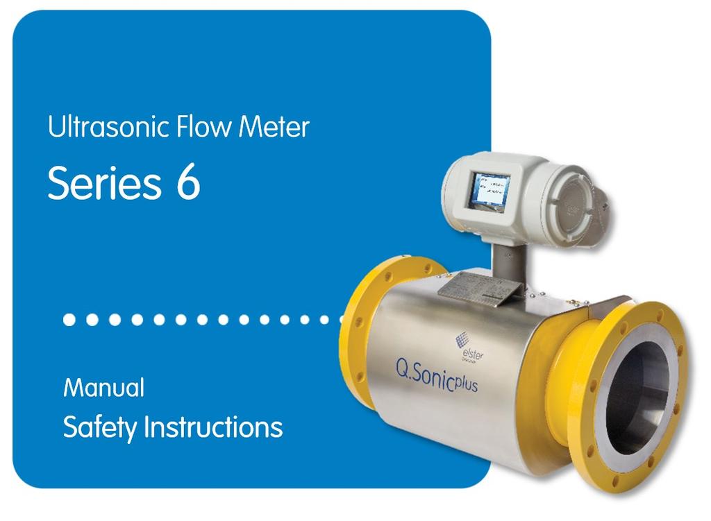
5 1 General Information 1 General Information 1.1 About these Instructions This manual contains safety instructions for installation, operation, and maintenance of the Ultrasonic Flow Meter (UFM) Series 6, models Q.Sonic atom, Q.Sonic plus, CheckSonic, Vx.Sonic and FlareSonic. In addition to providing essential information for proper operation and maintenance of the product, this manual offers important instructions to prevent accidents and serious damage in all stages of the product s lifespan; precommissioning, daily operations, and trouble-free maintenance. Before using any of the products please read this manual carefully, familiarise yourself with the operation of the product, and strictly follow the instructions. If you have any questions, or need further details on specific matters concerning this product, please do not hesitate to contact one of our staff members by at aftersales@elster-instromet.com (or see more contact information on page 2). This document only contains safety information for an Elster Series 6 UFM. For general information, please refer to the Operation and Maintenance Manual for your particular flow meter (latest valid revision). Please also consider reading the following Series 6 UFM information: Wiring Instructions, Shipping and Storage, and Modbus Protocol. These documents are available online at Please also refer to Appendix I References for a complete list of reference materials. 1.2 Limitation of Liability This manual is based on the latest information available. It is provided subject to alterations. We reserve the right to change the construction and/or configuration of our products at any time without obligation to update previously shipped equipment. UFM Series 6 Safety Instructions Page 5 of 38
6 General Information 1 The warranty provisions stipulated in the manufacturer's Terms of Delivery are applicable to the product. The manufacturer shall have no obligation in the event that: Repair or replacement of equipment or parts is required through normal wear and tear, or by necessity in whole or part by catastrophe, or the fault or negligence of the purchaser; The equipment, or parts, have been maintained or repaired by someone other than an authorized representative of the manufacturer, or have been modified in any manner without prior express written permission of the manufacturer; Non-original parts are used; Equipment is used improperly, incorrectly, carelessly or not in line with its nature and/or purpose; Use of this product with unauthorized equipment or peripherals, including, but not necessarily limited to, cables, testing equipment, computers, voltage, etc. The manufacturer is not responsible for the incidental or consequential damages resulting from the breach of any express or implied warranties, including damage to property, and to the extent permitted by law, damage for personal injury. Read through these Safety Instructions carefully before beginning any work. The manufacturer assumes no liability for loss and malfunctions that result from non-compliance with these instructions. We reserve the right to make technical changes within the scope of improving performance characteristics and continuous development of the device. Current warranty conditions in the General Terms and Conditions are available on our website: Page 6 of 38 Safety Instructions UFM Series 6
7 2 Text Labelling 2 Text Labelling This manual employs consistent visual cues and standard text formats to help you easily locate and interpret information. This information will help you quickly identify relevant content Presentation of Safety and Risk Instructions Hazard Warnings Hazard warnings indicate hazardous situations which may result in material damage and bodily harm or even death if disregarded. Hazard warnings are described below: DANGER WORD! Type of danger / consequences in case of non-compliance Avoiding danger Safety Instructions Safety instructions include notes and information which if disregarded may lead to functions not working correctly or not working at all. Safety instructions are described below: Safety instruction (optional) Safety instruction text Tips and Recommendations Tips include notes and information that make it easier for the user. Tips are described below: Heading (optional) Hint text UFM Series 6 Safety Instructions Page 7 of 38
8 Text Labelling Paragraph Formats This triangle prompts you for an action. This character will show you the immediate result of your action. Example Multi-row examples are marked by two continuous blue lines and the keyword Example Character Formats Example See Chapter 3.3 Hazardous Situations (p.15) Use References to additional information are marked with an arrow. If the arrow refers to information within the document, these references are formatted as hyperlinks in blue font. You can go directly to the corresponding section by clicking on the blue text. links (Hyperlink) Table 1: Character formats Page 8 of 38 Safety Instructions UFM Series 6
 is the part of the ultrasonic flow meter that is mounted in the piping system. All other components are mounted on the flow cell.")
9 3 Application and Operation 3 Application and Operation 3.1 System The ultrasonic flow meter comprises of the following main parts as listed below and seen in Figure 3-1. The flow cell (in yellow) is the part of the ultrasonic flow meter that is mounted in the piping system. All other components are mounted on the flow cell. SPU label (rear side) SPU Temperature Sensor (rear side) Main Type Plate Pressure Connection Ultrasonic Transducer Pressure Sensor Flow Cell Figure 3-1: Example of an Elster Ultrasonic Gas Flow Meter UFM Series 6 Safety Instructions Page 9 of 38
10 Application and Operation 3 Flow Meter components: The Signal Processing Unit (SPU) houses the flow meter electronics. Two Ultrasonic Transducers per flow measurement path. The spoolpiece (Flow Cell) designed for gas flow measurement. An optional Pressure Sensor. An optional Temperature Sensor. pm (or pr) Pressure Connection (for flow pressure); one or two (provided with adapter piece). The SPU Label (see subsequent sections) The Main Type Plate Caution! The ultrasonic flow meter is intended for flow measurement as indicated on the SPU label and the flow meter (main) type plate. Never exceed any limitations for use! Tip! This document provides essential details for safe installation and maintenance of the ultrasonic flow meter, including a nonexhaustive list of safety prescriptions provided in Annex C Safety Prescriptions (p. 33). It is also required to read and understand all other documentation of your flow meter; please see the reference list Appendix I References at the back of this manual. Alternatively, most documents are available online at The ultrasonic flow meter is to be operated on the local display or by remote control, for example, by means of a PC with the SonicExplorer software, as part of your specific flow meter. Page 10 of 38 Safety Instructions UFM Series 6
11 3 Application and Operation 3.2 SPU The Signal Processing Unit (SPU) houses the flow meter electronics and comprises the following user interfaces: SPU label (see the following paragraphs) Electrical user connections ( see Chapter 4 Installation and Chapter 5 Electrical Parameters) Local display (see the Operation and Maintenance manual of your particular flow meter, latest valid version) SPU - Special Conditions for Safe Use Contact the manufacturer for information on the dimensions of the flameproof joints. The enclosure is provided with special fasteners of property class A2-70. These special fasteners are only available from Elster. For FM approved products refer to Annex A Control Drawing (FM) for particular requirements SPU Label The ultrasonic flow meter is available with approval for use in hazardous areas according to ATEX, IECEx, FM Approval, or CSA. Always refer to the actual label information on your flow meter as well as this manual for correct use. Each SPU label comprises: Our company name and address Type of ultrasonic flow meter Model SPU Serial number Power: VDC / 20Wmax Year-Month Warning: Read instruction manual before operating device UFM Series 6 Safety Instructions Page 11 of 38

12 Application and Operation 3 Additional label information depending on the applicable approval (see following label examples) Please see below for an explanation of each label type using an Ultrasonic Flow Meter Series 6 Q.Sonic Plus model as an example. ATEX Certification The explosion proof housing has the following ATEX certification information: Classification: Ex II 2 G Ex d ia [ia] IIB+H2 T6 Gb IP66-50 C Tamb +60 C ATEX markings: II 2 G 0044 o 0044 is the Notified Body number of DEKRA Certification B.V. ATEX certificate reference: DEKRA 11ATEX0170 X Warning: Read instruction manual before operating device Figure 3-2: Example of an ATEX Label IECEx Certification The explosion proof housing has following IECEx certification information: Classification: Ex d ia [ia] IIB+H2 T6 Gb IP66-40 C Tamb +60 C IECEx certificate reference: IECEx DEK X Warning: Read instruction manual before operating device Page 12 of 38 Safety Instructions UFM Series 6
, T6 Type 4X FM approved mark Installation requirement: Seal fitting required")
13 3 Application and Operation Figure 3-3: Example of an IECEx Label FM Certification The explosion proof housing has the following FM certification information: Explosion proof for Class I, Division 1, Group A, B, C and D Intrinsically safe for Class I, Division 1, Group A, B, C and D Ta = -40 F to 140 F (-40 C to +60 C), T6 Type 4X FM approved mark Installation requirement: Seal fitting required within 1.5 inches of enclosure Warning: Read Instruction Manual (Control Drawing: /2) before operating device. A copy of the control drawing is available in Annex A Control Drawing (FM) (p.29). Figure 3-4: Example of an FM Label UFM Series 6 Safety Instructions Page 13 of 38
![Application and Operation 3 CSA Certification The explosion proof housing has the following CSA certification information: Explosion proof for Class I, Division 1, Group B, C and D T6 Ex d ia [ia]](/docs-images/89/99819087/images/14-0.jpg "IIB + H2 T6-50 C < Tamb < +60 C Type 4X IP66 CSA 13.70001043 Installation requirement: Seal all conduit within 1.")
14 Application and Operation 3 CSA Certification The explosion proof housing has the following CSA certification information: Explosion proof for Class I, Division 1, Group B, C and D T6 Ex d ia [ia] IIB + H2 T6-50 C < Tamb < +60 C Type 4X IP66 CSA Installation requirement: Seal all conduit within 1.50 inches in group B & C Warnings: o o Substitution of components may impair intrinsic safety. Read Instruction Manual (control drawing: /2) before operating device. A copy of the control drawing is available in Annex B Control Drawing (CSA) (p.31) Figure 3-5: Example of a CSA Label WARNING! Always refer to the label on the product itself for the correct information for your particular product. Do not use or keep the product outside of its specifications. Page 14 of 38 Safety Instructions UFM Series 6
15 3 Application and Operation 3.3 Hazardous Situations Read the instruction manual before operating device. Never open the explosion proof box with the electronics inside when meter is energized. Do not open the enclosure if explosive atmosphere may be present. Use the ultrasonic flow meter only for its intended application. Never use it outside of its intended application or limits. It is not allowed to perform repair and maintenance activities on an operating flow meter. The meter is pressurized and is used for dangerous media. Removing / exchanging parts during operation can cause severe harm or even death. The meter can be used for media within a specified range. Take care of proper grounding of the meter. To prevent water entering the electronics enclosure, firmly tighten the box when closing. Make sure O-rings on the covers are correctly fitted and in good condition. Take care that no dirt / particles are present on the gasket on the back compartment before closing. Also: Please see Annex C Safety Prescriptions. 3.4 Storage and Transportation The back and main compartments of the electronics enclosure may be equipped with a silica gel bag in the explosion safe box. Before powering up, take the silica gel bag out of its enclosure. Always store or transport the meter with a silica gel bag in the back and main compartments, to absorb excessive humidity. Replace the silica gel with a fresh one before it is saturated. Check on a regular basis (e.g. monthly). UFM Series 6 Safety Instructions Page 15 of 38
16 Installation 4 WARNING! Obey the rules and regulations that apply to hazardous area operations and those with respect to custody transfer regulations (sealing). 4 Installation 4.1 General It is the user s responsibility to ensure that the installation complies with appropriate regulations, including those required by applicable certifications. It is highly recommended to install the meter on a vibration free location. Continuous vibration or shocks may have negative effects on the construction of the flow meter. More information on installation of the ultrasonic flow meter in the pipeline is provided in the Operation and Maintenance manual of your particular flow meter (latest valid revision). This chapter provides information on the electrical user connections available on the SPU (see Figure 3-1). For additional wiring information see document: UFM Series 6 Wiring Instructions, listed in Appendix I References at the back of this manual. 4.2 Wiring User connections are available in the back compartment of the SPU. The transducers and optional pressure and temperature sensors are already factory connected. The electronics enclosure is provided with five M20 or ½ NPT size cable gland entries available to the user, as seen in Figure 4-2. Select and install the glands according to all applicable requirements, such as those stated in: Page 16 of 38 Safety Instructions UFM Series 6
17 4 Installation National and local regulations; the SPU documentation (this manual, order specification stating the type of entry holes) and on the SPU label; the certificate and manual of the glands; Specifications of the user wiring. It is recommended to use suitable armoured shielded cable to provide protection against mechanical damage and electrical interference. Important! Use a cable with suitable resistance, diameter, cores and length. If your ultrasonic flow meter is FM approved (see the SPU label), these special remarks are also applicable: Installations shall comply with the relevant requirements of the latest edition of the National Electrical Code (ANSI/NFPA 70). Installations shall comply with the latest edition of the manufacturer s instruction manual. For intrinsically safe installation in the United States of America, electrical equipment connected to the Associated Apparatus shall not use or generate more than 250 volts rms. For guidance on installations in the United States of America, see ANSI/ISA-RP , Installation of Intrinsically Safe Systems for Hazardous (Classified) Locations. Tampering and replacement with non-factory components may adversely affect the safe use of the system. Seal fitting is required within 1.5 inches of enclosure. Warning: See control drawing: /2 before operating device. A copy of the control drawing is available in Annex A Control Drawing (FM) (p.29). UFM Series 6 Safety Instructions Page 17 of 38
18 Installation 4 WARNING! Do not perform any modification of the products supplied. The volume of the SPU enclosure to fit user glands is less than 2 liters. Unused gland entries must be fitted with suitable certified stopping plugs. Before use ensure unused entries contain suitable certified plugs (and not temporary or transportation plugs). The connection between each gland or stopping plug and the enclosure must comply with the NEMA or IP class and the temperatures indicated on the SPU (e.g. by using a suitable IP washer). During transport and storage the electronics enclosure back and main compartment may contain a bag of silica gel to absorb excessive humidity. Remove the bags before powering the SPU. 4.3 System Specifications Power connection (TB1): 18 30VDC, 20 Watt maximum. 24 V Nominal. Cable max. 700m, max. 5 Ohm/wire Built-in surge protection Maximum cable core 2.5 mm 2 Page 18 of 38 Safety Instructions UFM Series 6
19 4 Installation WARNING! For compliance with EN-IEC (also harmonized under EU Low Voltage directive 2006/95/EC) the SPU requires an external power supply, limited-energy (< 30 Vdc max. 8A), and reinforced insulation between input and output by the safety transformer and appropriate distance between components on the PCB. Do not open the rear compartment when device is energized. The electronics requires a (preferably) 24VDC (nominal) power supply. A combined power supply and communication cable between the electronics enclosure and the external equipment can be used. For example; 2x2 wire (min. Ø 0.5 mm) twisted-pair max. 700m, max. 5Ω/wire. Armoured shielded cable is recommended to provide protection against mechanical damage and electrical interference. Cathodic Protection! In case the ultrasonic flow meter body is connected to a cathodic protection system, DO NOT CONNECT the ground of the external power supply to the ground (GND) of the field terminal power connection (TB1). UFM Series 6 Safety Instructions Page 19 of 38
20 Installation DSL / Network Connections (TB2 & J4) DSL Network / Ethernet connections Power over Ethernet Maximum cable core 1.5 mm Outputs / Communication (TB3) Two configurable opto-coupler outputs, max 12mA. Two isolated passive/active mA analogue outputs, 16 bit resolution. Two opto-coupler outputs, max 12mA (shared with analogue outputs.) Two RS232/RS485 (software configurable) ports: o Cable: 3 x 2 wire (min 0.5 mm 2 ), shielded max. 15m, max. 2,5 Ohm/wire o Programmable up to bps. Maximum cable core 1.5 mm2 IS Inputs (optional) (TB4/TB5). For electrical parameters, refer to Chapter 4.4 Field Terminal Board (p.21) Two isolated passive/active mA analogue inputs, 16 bit resolution. Maximum cable core 1.5 mm 2 Page 20 of 38 Safety Instructions UFM Series 6

21 4 Installation 4.4 Field Terminal Board The field terminal board in the back compartment of the electronics enclosure is for customer connections. Figure 4-1: Field Terminal Board in Electronics Enclosure 4.5 Transducer Connections The Analogue board PCB has a terminal block to connect the transducers for each transducer and the optional pressure sensor. The transducers are connected using a single connector. Figure 4-2: Field Terminal Board with Labelled Connections UFM Series 6 Safety Instructions Page 21 of 38

22 Installation Pressure Connection All forged meters bodies sizes 3 (DN80) to 12 (DN300) are supplied with ½ NPT Pr adapters and ½ NPT blind plugs. Adapters and plugs are sealed with PTFE tape and hydrotested with the meter body. After the hydrotest, adapters and plugs are painted together with the meter body. Where necessary, seals on Pm (Pr) point adapter (at both ends) and the blind plug should be replaced with appropriate sealant for the application. Hold the Pr point adapter with a 30mm wrench while removing the blind plug or fitting new connections. Attention! ALWAYS CHECK NEWLY MADE CONNECTIONS FOR LEAKS. Please see Figure 4-3. These places need to be checked for leaks when a new pressure connection has been made. Figure 4-3: Example of Pressure connection with Pressure Adapter 4.7 Maintenance For maintenance refer to the UFM Series 6 Operation and Maintenance Manual for your particular meter (latest valid revision). Please see Appendix I References for a complete list of resources. Page 22 of 38 Safety Instructions UFM Series 6
23 5 Electrical Parameters 5 Electrical Parameters Intrinsically Safe Field Terminal Board (see Figure 4-2) Terminals IS_opt_C1, IS_opt_C ma connection with HART, label IS_opt_C1 and IS_opt_C2 circuit (terminals P+ and P-) (for pm flow pressure sensor) In type of protection intrinsic safety, with the following maximum values: Uo Io Po Lo Co = 23.1 V = 109 ma = 629 mw = 1 mh = 0.1 μf Terminals IS_opt_A1, IS_opt_A2, IS_opt_A3, IS_opt_A4 4-wire PT 100 (external) temperature sensor input with label IS_opt_A1, IS_opt_A4, IS_opt_A2 and IS_opt_A3 circuit (terminals I+, I-, U+ and U-): In type of protection intrinsic safety, with the following maximum values: Uo Io Po Lo Co = 5.9 V = 9.8 ma = 15 mw = 10 mh = 0.5 μf UFM Series 6 Safety Instructions Page 23 of 38
24 Electrical Parameters 5 Intrinsically Safe Terminals IS_opt_B1, IS_opt_B3 Namur pulse input #1, with label IS_opt_B1 and IS_opt_B3 circuit (terminals Z1+ and Z1-): In type of protection intrinsic safety, with the following maximum values: Uo Io Po Lo Co = 9.1 V = 37 ma = 84 mw = 10 mh = 0.5 μf Terminals IS_opt_B2, IS_opt_B4 Namur pulse input #2, with label IS_opt_B2 and IS_opt_B4 circuit (terminals Z2- and Z2+): In type of protection intrinsic safety, with the following maximum values: Uo Io Po Lo Co = 9.1 V = 37 ma = 84 mw = 10 mh = 0.5 μf Table 2: Intrinsically Safe Parameters Non- Intrinsically Safe Terminals TB1 1,2,3 Terminals TB2, TB3 and J4 Power supply connection (Um = 250V) pins: VDC nom. (18-30 VDC, 20 W) 2. 0 V 1. Do not connect ( see Chapter 4 Installation [p.16]) Non-IS data circuits (Um = 250V) TB2: DSL / Network connections TB3: Output / Communication ports J4: Ethernet Table 3: Non - Intrinsically Safe Parameters Page 24 of 38 Safety Instructions UFM Series 6
25 Index 6 Index A ATEX Certification, 12 C Cathodic Protection, 19 Character Formats, 8 CSA Certification, 14 D Dokuthek, 5, 10 DSL / Network Connections (TB2 & J4), 20 E Electrical Parameters, 23 EN-IEC Compliance, 19 F Field Terminal Board, 21 FM Approval, 17 FM Certification, 13 G General Terms and Conditions, 6 I IECEx Certification, 12 Installation, 16 Intrinsically Safe Terminals, 23 L Limitation of Liability, 5 N Non- Intrinsically Safe Terminals, 24 O Outputs / Communication (TB3), 20 P Paragraph formats, 8 Power connection (TB1):, 18 Pressure Connection, 22 R References, 26 S Safety instructions, 7 SPU, 11 SPU Labels, 11 Storage, 15 System, 9 T Text Labelling, 7 Transducer Connections, 21 Transportation, 15 W Wiring, 16 UFM Series 6 Safety Instructions Page 25 of 38
26 Appendix I References Appendix I References All references listed below can be obtained from Elster. Additionally, most references are available online at: [1] UFM Series 6 Q.Sonic plus Operation and Maintenance Manual SAP Ref.: Doc. No.: (last valid revision) [2] UFM Series 6 CheckSonic Operation and Maintenance Manual SAP Ref.: Doc. No.: (last valid revision) [3] UFM Series 6 Q.Sonic max Operation and Maintenance Manual SAP Ref.: Doc. No.: (last valid revision) [4] UFM Series 6 Wiring Instructions SAP Ref.: Doc. No.: (last valid revision) [5] UFM Series 6 Shipping and Storage Manual SAP Ref.: Doc. No.: (last valid revision) [6] UFM Series 6 Safety Instructions SAP Ref.: Doc. No.: (last valid revision) [7] UFM Series 6 Modbus Protocol SAP Ref.: Doc. No.: (last valid revision) Page 26 of 38 Safety Instructions UFM Series 6
27 Appendix I References [8] UFM Series 6 Transducer Exchange at Atmospheric Conditions SAP Ref.: Doc. No.: /02/2 (last valid revision) [9] Retraction Tool NG Transducers SAP Ref.: Doc. No.: /2 (last valid revision) [10] UFM Series 6 Exchanging PCB boards in TIP SAP Ref.: Doc. No.: /2 (last valid revision) [11] UFM Series 6 Exchanging Boards at the Rear Compartment of the SPU SAP Ref.: Doc. No.: /2 (last valid revision) [12] External VDSL Range Extender User Manual SAP Ref.: Doc. No.: (last valid revision) [13] UFM Series 6 SonicExplorer Software Application Manual SAP Ref.: Doc. No.: (last valid revision) UFM Series 6 Safety Instructions Page 27 of 38
28 Page 28 of 38 Safety Instructions UFM Series 6
29 Annex A Control Drawing (FM) Drawing /2 (FM Approved) UFM Series 6 Safety Instructions Page 29 of 38
30 Annex A Control Drawing (FM) Page 30 of 38 Safety Instructions UFM Series 6
31 Annex B Control Drawing (CSA) Drawing /2 (CSA Approved) UFM Series 6 Safety Instructions Page 31 of 38
32 Annex B Control Drawing (CSA) 5 Page 32 of 38 Safety Instructions UFM Series 6
33 Annex C Safety Prescriptions Ultrasonic Flow Meter Series 6 This annex includes a non-exhaustive list of important safety prescriptions for a Series 6 Ultrasonic Flow Meter. At dispatch the latest version of this Annex is attached to the UFM. For safety reasons it is required to read and understand the entire document to which this Annex belongs: UFM Series 6 Safety Instructions. Ref: (last valid revision). UFM Series 6 Safety Instructions Page 33 of 38
34 Annex C Safety Prescriptions Safety Prescriptions - Ultrasonic Flow Meter Series 6 Read the instruction manuals before handling or operating the device! See Appendix I References at the back of this manual for a list of all available information. Storage and transportation (also refer to the UFM Series 6 Shipping and Storage Manual. Ref: ): o o o o o Use a fork-lift or fork-truck for transportation, loading and unloading of the packed ultrasonic gas flow meter. The wooden cover of the box is not suitable for the use of strap belts and a crane. If the package has been removed from the product, lifting and moving may only be carried out using suitable, properly fitted lifting lugs. Take care that the meter will be installed on a vibration free location. Continuous vibration or shocks may have disadvantageous effect on the construction of the flow meter. The back and main compartments of the electronics enclosure may be provided with a silica gel bag in the Explosion proof box. Before powering, take the silica gel bag out of the enclosure. Always store or transport the meter with a silica gel bag in the SPU box, to absorb excessive humidity. Replace the silica gel with a fresh one before it is saturated. Check on a regular basis (e.g. monthly). All forged meters bodies sizes 3 (DN80) to 12 (DN300) are supplied with ½ NPT Pr adapters and ½ NPT blind plugs. Adapters and plugs are sealed with PTFE tape and hydrotested with meter body. After that hydrotest, adapters and plugs are painted together with meter body. Where necessary, seals on Pm Page 34 of 38 Safety Instructions UFM Series 6
35 Annex C Safety Prescriptions (Pr) point adapter (at both ends) and the blind plug shall be replaced with appropriate sealant for the application. Hold Pr point adapter with 30mm wrench while removing blind plug or fitting new connections. ALWAYS CHECK NEWLY MADE CONNECTIONS FOR LEAKS. IT IS NOT ALLOWED TO DO A HYDROTEST WHEN TRANSDUCERS ARE INSTALLED ON THE ULTRASONIC FLOW METER. Water can be trapped between the transducers and the spoolpiece. It is very hard to remove this afterwards. This water can cause the ultrasonic flow meter to operate incorrectly. Installation, maintenance and replacement may only be carried out by qualified personnel under safe conditions. Always use a gas detector during servicing of the meter! Obey the rules and regulations that apply to hazardous area operations and those with respect to custody transfer regulations (sealing). Pressurized parts involved. When executing any work, comply with the regulations that are specifically stipulated applicable to pressurized installations in a possible explosive danger area (as the case may be). Explosion proof box with the electronics inside may never be opened when meter is energized. Do not open the enclosure when explosive atmosphere may be present (see label & manual). UFM Series 6 Safety Instructions Page 35 of 38
36 Annex C Safety Prescriptions Use the ultrasonic meter only for its intended application. Restrict to media and pressure & temperature limits. Never use an ultrasonic meter outside of these limits (for information see name plate). It is not allowed to perform repair and maintenance activities on an operating ultrasonic meter. The meter is pressurized and is used for dangerous media. Removing / exchanging parts during operation can cause severe harm or even death. When a non-retractable transducer needs to be taken out of the flow cell, the meter and the process line must be de-pressurized and have ambient temperature suitable to handle. In case of retractable transducers, it is only allowed to exchange these retractable transducers during operation of the meter when the procedure for exchanging transducers, as described in the manual from the manufacturer, is strictly followed. Be careful when removing transducers, media from the process line may still come out. This media can be poisonous, inflammable or dangerous in a different kind. Take the necessary precautions to avoid these dangerous situations. If any doubts arise about the type of transducers / manual please contact manufacturer: aftersales@elster-instromet.com or your local agent. When the meter needs to be taken out of the process line, this process line must be de-pressurized. The meter can be used for media with high or low temperatures, within the specified range. Any contact with the meter can cause severe harm. Page 36 of 38 Safety Instructions UFM Series 6
37 Annex C Safety Prescriptions Always use the correct tools and parts. Never use pneumatically powered tools, electrically powered tools or hydraulically powered tools to perform retraction of an Ultrasonic Transducer. Always leak test the meter after installation. Take care of proper grounding of the meter. To prevent water entering the flameproof certified box, firmly tighten the box when closing. Take care of preventive inspection of the meter (environment - & weather influence). ATTENTION! Removing Internal Coating and Tape BEFORE INSTALLATION REMOVE CONSERVING COATING INSIDE SPOOLPIECE. Before this ultrasonic gas flow meter was shipped a conservative protection layer was applied on the inside of the meter. It was applied immediately after the internal of the meter had been in contact with the atmosphere (oxygen) and should be removed prior to installing the meter in-line or calibration. The face of the transducers is not coated. The face of some particular transducers might be protected against the coating by means of tape that can be removed easily. Prior to installation of the flow meter verify there is no tape. UFM Series 6 Safety Instructions Page 37 of 38
38 Annex C Safety Prescriptions Types of coatings that may be applied in the spoolpiece of an ultrasonic flow meter: VCI Foam: Vapour Corrosion Inhibitor (VCI) foam has been applied if its type reference is mentioned above. The foam needs to be removed before installation. The foam itself is not harmful and can be thrown away as standard garbage. It is recommended to use gloves when handling the foam. Tectyl: Tectyl coating has been applied if its type reference is mentioned above. To remove Tectyl coating use cloth and a solvent (e.g. solvent thinner). Avoid the use of chlorinated or highly aromatic solvents. If the Tectyl layer is dried out removal of it will take some effort. Do not clean the face of the transducer with solvent. If cleaning of the transducer is needed, which should not be the case, use only a dry cloth. Oil: Oil coating has been applied if its type reference is mentioned above. Removal of oil is not really needed. Because it is not dried out, the gas-flow will certainly remove the present layer. However, it is preferred to remove it using cloth and a solvent. Do not clean the face of the transducer with solvent. If cleaning of the transducer is needed, which should not be the case, use only a dry clo Page 38 of 38 Safety Instructions UFM Series 6
OPTIBAR DP 7060 Supplementary Instructions
 OPTIBAR DP 7060 Supplementary Instructions Differential pressure transmitter Category ATEX II 1/2G, 2G Ex db ia IIC T6...T1 Ga/Gb, Gb IECEx Ex db ia IIC T6...T1 Ga/Gb, Gb Housing Aluminium: Single chamber,
AM54. Armored Variable Area Flowmeter Series AM54331/32 Series AM54371/72/73/74 Series AM54431/32 Series AM54471/72/73/74
 AM54 Instruction Bulletin North American Installation Addendum Document Number PN25016 Armored Variable Area Flowmeter Series AM54331/32 Series AM54371/72/73/74 Series AM54431/32 Series AM54471/72/73/74
Installation Guide SmartRadar FlexLine
 Contact Information: Head Office - Delft, The Netherlands Honeywell Enraf Delftechpark 39, 2628 XJ Delft PO Box 812, 2600 AV Delft The Netherlands Tel.: +31 (0)15 2701 100 Fax: +31 (0)15 2701 111 E-mail:
VERSAFLOW VORTEX Supplementary instructions
 VERSAFLOW VORTEX Supplementary instructions Vortex flowmeter Equipment category II 2G CONTENTS VERSAFLOW VORTEX 1 Safety instructions 3 1.1 General notes... 3 1.2 EC conformity... 3 1.3 Approval according
OPTIWAVE X500 Supplementary Instructions
 OPTIWAVE X500 Supplementary Instructions OPTIWAVE 3500 C OPTIWAVE 6500 C OPTIWAVE 7500 C Supplementary Instructions for ATEX applications KROHNE CONTENTS OPTIWAVE X500 1 General safety information 4 1.1
Quick Start Guide For the
 A Leader in Level Measurement Quick Start Guide For the Universal IV Lite and Universal IV Pro Model Transmitters 2-Wire RF Admittance / Capacitance Level Measurement System with HART Protocol For Assistance
Additional Operating Instructions SITRANS F. Vortex flowmeters. SITRANS FX330 Ex-d.
 Additional Operating Instructions SITRANS F Vortex flowmeters Ex-d Edition 09/208 CONTENTS Safety instructions 3. General notes... 3.2 EU conformity... 3.3 Approval according to the IECEx scheme... 3.4
Additional Operating Instructions SITRANS F. Vortex flowmeters. SITRANS FX330 Ex-i.
 Additional Operating Instructions SITRANS F Vortex flowmeters Ex-i Edition 09/2018 CONTENTS 1 Safety instructions 3 1.1 General notes... 3 1.2 EU conformity... 3 1.3 Approval according to the IECEx scheme...
Certificate of Compliance
 FF0 001 Certificate of Compliance Certificate: 70116284 (LR 064969_0_00) Issued to: Mine Safety Appliances Company North American Division 1000 Cranberry Woods Dr Cranberry Township, Pennsylvania 16066-5296
Flameproof Manual Call Points
 Operating instructions Additional languages www.r-stahl.com CS & Clifford & Snell Contents General Information.... Manufacturer.... Information regarding the operating instructions.... Further documents....
MICROpeL 75 Combustible Gas Sensor Part Number: PM
 MICROpeL 75 Combustible Gas Sensor Part Number: PM759-000 Key Features & Benefits: ATEX, UL and CSA Approvals Withstands EN/IEC 60079-0 impact test Enhanced H 2 S and silicone poison resistance Reduced
IECEx Certificate of Conformity
 IECEx Certificate of Conformity INTERNATIONAL ELECTROTECHNICAL COMMISSION IEC Certification Scheme for Explosive Atmospheres for rules and details of the IECEx Scheme visit www.iecex.com Certificate IECEx
Certificate of Compliance
 FF0 001 Certificate of Compliance Certificate: 70116279 (LR 025993_0_000) Issued to: General Monitors, Incorporated 26776 Simpatica Circle Lake Forest, California 92630 USA Attention: Larry Vlagea The
INSTRUCTION MANUAL IS-mB1 Minialite Intrinsically Safe Round LED Beacon
 INSTRUCTION MANUAL Minialite Intrinsically Safe Round LED This instruction sheet describes installations which conform to EN60079:Part14:2008 Electrical Installation in Hazardous Areas. When designing
Regulated Ex-Heater HEX with internal controller, HEX with external controller II 3 G II 3 D
 Regulated Ex-Heater HEX5-1.08 with internal controller, HEX5-2.08 with external controller II 3 G II 3 D Instruction Manual Version 1.02.00 Dear customer, we have made up this operating manual in such
Additional Operating Instructions SITRANS F. Vortex flowmeters. SITRANS FX330 Ex-nA.
 Additional Operating Instructions SITRANS F Vortex flowmeters Ex-nA Edition 08/207 CONTENTS Safety instructions 3. General notes... 3.2 EU conformity... 3.3 Approval according to the IECEx scheme... 3.4
Manual Power relay SR853
 Manual Power relay SR853 Product types SR853.8.x.x, Rev. 1 SR853 manual page2 The symbols WARNING, CAUTION, NOTE This symbol warns of a serious hazard. Failure to observe this warning may result in death
4) Intrinsic Safety Certification
 Intrinsic Safety Certification") INSTRUCTION MANUAL Minialert Intrinsically Safe Round Combined Unit Section Volume Control Tone Generator S2 S3 Tone Selection Switches Fig 1 Simplified block diagram The combined unit is CE marked for
INSTRUCTION MANUAL Minialert Intrinsically Safe Round Combined Unit Section Volume Control Tone Generator S2 S3 Tone Selection Switches Fig 1 Simplified block diagram The combined unit is CE marked for
User s Manual YTA610 and YTA710 NEPSI Certification
 User s Manual YTA60 and YTA70 NEPSI Certification [Option code: /NS, /NS5 and /NF] st Edition . INTRODUCTION Thank you for purchasing the YTA60 and YTA70 Temperature transmitters. This manual contains
SET-2000 Oil/Sludge. Alarm Device for Oil Separators. Installation and Operating Instructions
 SET-000 Oil/Sludge Alarm Device for Oil Separators Copyright 007 Labkotec Oy We reserve the right for changes without notice TABLE OF CONTENTS GENERAL... INSTALLATION... 4. SET-000 Oil/Sludge Control Unit...
Safety instructions VEGADIS DIS61.CC/O** VEGADIS DIS81.CC/O******
 Safety instructions VEGADIS DIS61.CC/O** VEGADIS DIS81.CC/O****** CSA 14.2662675 Ex ia IIC T6 Ga, Gb 0044 Document ID: 48924 Contents 1 Area of applicability... 3 2 General information... 3 3 Technical
Operating Instructions Edition 02/2007
 Operating Instructions Edition 02/2007 Temperature Transmitter 7NG3214 with PROFIBUS PA 7NG3215 with FOUNDATION Fieldbus sitrans Introduction 1 General safety notes 2 SITRANS T Temperature transmitter
SET-2000 Oil/Sludge 12 VDC
 Labkotec Oy Myllyhaantie 6 FI-33960 PIRKKALA FINLAND Tel: + 358 29 006 260 Fax: + 358 29 006 1260 12.2.2015 Internet: www.labkotec.fi 1/14 SET-2000 Oil/Sludge 12 VDC Alarm Device for Oil Separators with
INSTRUCTION MANUAL. SIL 3 - SIL 2 IIB Group Power Supply for Hazardous Area Equipment DIN-Rail Model PSD1001C PSD1001C
 PSD1001C INSTRUCTION MANUAL SIL 3 SIL 2 IIB Group Power Supply for Hazardous Area Equipment DINRail Model PSD1001C PSD1001C SIL 3 SIL 2 IIB Group Power Supply for hazardous Area Equipment ISM006510 General
Translation of the assembly instructions with operating instructions and technical appendix
 BA Ex-SBU Switch box type SBU-x(1,2,3)x Translation of the assembly instructions with operating instructions and technical appendix In accordance with EU ATEX Directive 2014/32/EU In accordance with EU
OilSET Installation and Operating Instructions. Oil Separator Alarm Device
 Labkotec Oy Myllyhaantie 6 FI-33960 PIRKKALA FINLAND Tel: +358 29 006 260 Fax: +358 29 006 1260 18.11.2010 Internet: www.labkotec.fi 1/10 OilSET-1000 Oil Separator Alarm Device Copyright 2010 Labkotec
Additional Information. Introduction. Temperature transmitter for all communications protocols. Redundancy thanks to two inputs. Measurement made easy
 ABB MEASUREMENT & ANALYTICS COMMISSIONING INSTRUCTION TTF300 Field-mount temperature transmitter Temperature transmitter for all communications protocols. Redundancy thanks to two inputs. Measurement made
Dräger Polytron 8100 EC Detection of toxic gases and oxygen
 Dräger Polytron 8100 EC Detection of toxic gases and oxygen The Polytron 8100 EC is Dräger s top of the line explosion-proof transmitter for the detection of toxic gases or oxygen It uses a high performance
Certificate of Compliance
 FF0002 Certificate of Compliance Certificate: 2792948 Issued to: Siemens Canada Limited 1954 Technology Drive Peterborough, ON K9J 7B1 Canada Attention: Mr. Lee Rogers The products listed below are eligible
INSTRUCTION MANUAL (ATEX / IECEx)
") INSTRUCTION MANUAL (ATEX / IECEx) BExS110D and BExS110D-R Sounder For use in Flammable Gas and Dust Atmospheres BExS110D BExS110D-R 1) Warnings DO NOT OPEN WHEN AN EXPLOSIVE ATMOSPHERE IS PRESENT DO NOT
INSTRUCTION MANUAL (ATEX / IECEx) BExS110D and BExS110D-R Sounder For use in Flammable Gas and Dust Atmospheres BExS110D BExS110D-R 1) Warnings DO NOT OPEN WHEN AN EXPLOSIVE ATMOSPHERE IS PRESENT DO NOT
SET Installation and Operating Instructions. Level switch for one sensor
 Labkotec Oy Myllyhaantie 6 FI-33960 PIRKKALA FINLAND Tel.: +358 29 006 260 Fax: +358 29 006 1260 7.11.2013 Internet: www.labkotec.fi 1/14 SET-1000 Level switch for one sensor Copyright 2013 Labkotec Oy
OPTIBAR P 1010/2010 C Supplementary instructions
 OPTIBAR P 1010/2010 C Supplementary instructions Pressure transmitter Equipment category II 1G / Ga, II 1D / Da in protection type intrinsic safety Exi KROHNE CONTENTS OPTIBAR P 1010/2010 C 1 Safety instructions
SET-2000 Hi Level/Oil
 Labkotec Oy Labkotie 1 FI-36240 KANGASALA FINLAND Tel: + 358 29 006 260 Fax: + 358 29 006 1260 13.03.2008 Internet: www.labkotec.fi Alarm Device for Oil Separators Copyright 2008 Labkotec Oy We reserve
4P75 CiTipeL Combustible Gas Sensor Part Number: PM
 Product Datasheet 4P75 Document Purpose The purpose of this document is to present the performance specification of the 4P75 CiTipeL. This document should be used in conjunction with Operating Principles
DET-TRONICS SPECIFICATION DATA. Eagle Quantum EQ2200UVHT For Use With C7050B Continuous Duty High Temperature UV Flame Detector DESCRIPTION
 DET-TRONICS SPECIFICATION DATA Eagle Quantum EQ2200UVHT For Use With C7050B Continuous Duty High Temperature UV Flame Detector DESCRIPTION The EQ2200UVHT UV Flame Detector is used with the Eagle Quantum
Intrinsically Safe, NEMA 4, Type 4X, IP67 Loop-Powered Meter
 PD685 Intrinsically Safe, NEMA 4, Type 4X, IP67 Loop-Powered Meter Actual Size Digits C US Intrinsically Safe 3½ Digits LARGE DISPLAY NEMA 4, Type 4X, IP67 Loop-Powered Field-Mount Process Meter 4-20 ma
IECEx Certificate. INTERNATIONAL ELECTROTECHNICAL COMMISSION IEC Certification Scheme for Explosive Atmospheres
 INTERNATIONAL ELECTROTECHNICAL COMMISSION IEC Certification Scheme for Explosive Atmospheres for rules and details of the IECEx Scheme visit www.iecex.com Certificate No.: Certificate history: Status:
Inspection Light LED 6149/2. Operating instructions EN EN EN EN EN EN EN EN EN EN EN EN EN EN EN EN EN EN EN EN EN EN EN EN
 Inspection Light LED Operating instructions Additional languages www.stahl-ex.com Contents 1 General Information...3 1.1 Manufacturer...3 1.2 Information regarding the operating instructions...3 1.3 Conformity
Model 144H. Product Data Sheet , Rev DB February Content
 Rosemount 144 PC-Programmable Temperature Transmitter Provides an installation-ready solution for temperature monitoring applications using Complete Point Solutions (CPS) Increases measurement accuracy
Manual Isolating Barrier D461R1 (Revision 01)
") D461R1 Manual Isolating Barrier D461R1 (Revision 01) Product Manual Original Instructions valid for models D461R1.11 with 1x signal input into 1x isolated signal output D461R1.12 with 1x signal input into
D461R1 Manual Isolating Barrier D461R1 (Revision 01) Product Manual Original Instructions valid for models D461R1.11 with 1x signal input into 1x isolated signal output D461R1.12 with 1x signal input into
INSTALLATION OPERATION AND MAINTENANCE INSTRUCTIONS FAW, FAW-C & FAW-C-T TYPE AIR WARMERS FCR & FCR-A TYPE CONVECTORS
 INSTALLATION OPERATION AND MAINTENANCE INSTRUCTIONS FAW, FAW-C & FAW-C-T TYPE AIR WARMERS FCR & FCR-A TYPE CONVECTORS STW & STW-T SAFE AREA AIR WARMERS HFT, AFT & SAT TYPE AIR THERMOSTATS Please read these
4P-90 CiTipeL Combustible Gas Sensor Part Number: PM
 Key Features & Benefits: ATEX, UL and CSA Approvals Withstands EN/IEC 60079-0 impact test Enhanced H 2 S and silicone poison resistance 4P-90 CiTipeL Combustible Gas Sensor Part Number: PM143-000 Performance
MANUAL Overflow sensor NVF-104/34-PF
 PROCESS AUTOMATION MANUAL Overflow sensor NVF-104/34-PF ISO9001 0102 Overflow sensor NVF-104/34-PF With regard to the supply of products, the current issue of the following document is applicable: The
Dräger Polytron 8310 IR Detection of flammable gases and vapour
 Dräger Polytron 8310 IR Detection of flammable gases and vapour The Dräger Polytron 8310 IR is an advanced explosion proof transmitter for the detection of combustible gases in the lower explosion limit
OilSET-1000 (12 VDC)
") Labkotec Oy Myllyhaantie 6 FI-33960 PIRKKALA FINLAND Tel: +358 29 006 260 Fax: +358 29 006 1260 Internet: www.labkotec.fi 20.03.2009 1/11 OilSET-1000 (12 VDC) Oil Separator Alarm Device Copyright 2009
Labkotec Oy Myllyhaantie 6 FI-33960 PIRKKALA FINLAND Tel: +358 29 006 260 Fax: +358 29 006 1260 Internet: www.labkotec.fi 20.03.2009 1/11 OilSET-1000 (12 VDC) Oil Separator Alarm Device Copyright 2009
Dräger Polytron 8100 EC Detection of toxic gases and vapors
 Dräger Polytron 8100 EC Detection of toxic gases and vapors The Polytron 8100 EC is Dräger s top of the line explosion proof transmitter for the detection of toxic gases or oxygen It uses a high performance
Officine Meccaniche M.A.M. series for command, control, signaling and/or automation. DOCUMENT IS-EJB-A-14 rev. 0
 Officine Meccaniche M.A.M. Apparecchiature Antideflagranti DOCUMENT IS-EJB-A-14 rev. 0 Instructions Flameproof enclosures EJB../W series for command, control, signaling and/or automation Emission date:
MANUAL Oil Level Sensor
 PROCESS AUTOMATION MANUAL Oil Level Sensor KVF-104-PF ISO9001 0102 With regard to the supply of products, the current issue of the following document is applicable: The General Terms of Delivery for Products
YTA Series Temperature Transmitters [Style: S3] EN :2006, -11:2007, -26:2007. Supply circuit: Ui=30 V, Ii=165 ma,
![YTA Series Temperature Transmitters [Style: S3] EN :2006, -11:2007, -26:2007. Supply circuit: Ui=30 V, Ii=165 ma,](/thumbs/89/98785336.jpg "YTA Series Temperature Transmitters [Style: S3] EN :2006, -11:2007, -26:2007. Supply circuit: Ui=30 V, Ii=165 ma,") User s Manual YTA Series Temperature Transmitters [Style: S3] Manual Change No. 10-008 Please use the attached sheets in the following manuals when the product is with /KU2 option and EN60000 Series based
User s Manual YTA Series Temperature Transmitters [Style: S3] Manual Change No. 10-008 Please use the attached sheets in the following manuals when the product is with /KU2 option and EN60000 Series based
Pressure sensors. Ex ia I / IIC T6 acc. to ATEX. Features. Description. Measuring ranges. Applications
 Force Pressure Temperature Switch Pressure sensors Ex ia I / IIC T6 acc. to ATEX with internal diaphragm with front flush diaphragm Accuracy: 0,25% and 0,5 % Standard output: 4...20 ma; 2-wire system Description
Report No EC. 1 Windsor Dials, Windsor, Berkshire, UK. SL4 1RS ATEX CERTIFICATION REPORT. Electronstandart-pribor
 Report No. 3040249EC FM Approvals Ltd 1 Windsor Dials, Windsor, Berkshire, UK. SL4 1RS ATEX CERTIFICATION REPORT Product: Model and/or Type Reference: Flame Detector IPES-IR3 Description of the Product:
Technical Data. General specifications Switching element function Rated operating distance s n 4 mm
 0102 Model Number Features 4 mm non-flush Accessories BF 12 Mounting flange, 12 mm Technical Data specifications Switching element function NAMUR, NO Rated operating distance s n 4 mm Installation non-flush
OilSET Installation and Operating Instructions. Oil Separator Alarm Device with SET/DM3AL sensor
 Labkotec UK Ltd Adminicle House 1 Lumb Lane Audenshaw Manchester M34 5WH GREAT BRITAIN Tel: 0844 3350 477 Fax: 0161 4281 179 E-mail: info@labkotec.co.uk 10.8.2012 Internet: www.labkotec.co.uk 1/13 OilSET-1000
Annubar Flowmeter Series
 Reference Manual Appendix B Approvals Annubar Flowmeter Series Hazardous Locations Installations.................. page B-1 Rosemount 3051SFA Product Certifications.......... page B-1 Rosemount 3095MFA
CONTROL BE MADE CHANGES MAY NOT. Page 1
 HI 6020IT and HI 6020JB US & Canada Hazardous Locations User Guide (Class I, II, III, Division 1, Class I, Zone 0 and Zone 20) Hardy Process Solutions Document Number: : 0596-0352-01 REV A CONTROL LLED
ATM Lighting sp. z o.o
 INSTALLATION AND MAINTENANCE MANUAL FOR EXPLOSIONPROOF LIGHT FITTING EXL210LED Carefully read the instructions before mounting the light fitting. ATM Lighting sp. z o.o., ul. Budowlanych 31, 80-298 Gdańsk,
Instructions. Explosion Proof Smoke Detector U Rev: 9/
 Instructions Explosion Proof Smoke Detector U0. Rev: 9/ 9-7 Table of Contents OVERVIEW... FEATURES... BENEFITS... SPECIFICATIONS... OPERATION... Warm Up... Outputs... Integral Wiring Compartment... LED...
OMC Ex interface unit. Manual. Version 1.2 August Author: Observator Instruments
 OMC-158-2 Ex interface unit Manual Version 1.2 August 2017 Author: Observator Instruments Revisions: 0.1 (October 2016) First issue 0.2 (December 2016) Prototype 0.3 (January 2017) Test release 1.0 (March
Rosemount 148 Temperature Transmitter. Quick Start Guide , Rev GA September 2016
 Rosemount 148 Temperature Transmitter 00825-0100-4148, Rev GA NOTICE This guide provides basic guidelines for the Rosemount 148. It does not provide instructions for detailed configuration, diagnostics,
INSTALLATION OPERATION AND MAINTENANCE INSTRUCTIONS EXHEAT INDUSTRIAL FLR & FLRA TYPE FLAMEPROOF RADIATORS
 INSTALLATION OPERATION AND MAINTENANCE INSTRUCTIONS EXHEAT INDUSTRIAL FLR & FLRA TYPE FLAMEPROOF RADIATORS Please read these instructions thoroughly before installation and ensure they are passed on to
IECEx Certificate of Conformity
 Page 1 of 10 IECEx Certificate of Conformity INTERNATIONAL ELECTROTECHNICAL COMMISSION IEC Certification Scheme for Explosive Atmospheres for rules and details of the IECEx Scheme visit www.iecex.com Certificate
Operating Instructions
 Operating Instructions MSi-JM0100-USB R. STAHL HMI Systems GmbH Adolf-Grimme-Allee 8 D 50829 Köln Operating Instructions Version: 01.00.03 Issue date: 29.06.2017 Disclaimer Disclaimer Publisher and copyright
Earth-Rite II PLUS Static Earthing System
 READ MANUAL BEFORE COMMENCING WITH INSTALLATION EN Earth-Rite II PLUS Static Earthing System P1 PLUS - DC Supply Installation & Operating Instructions The safety of any system incorporating the equipment
INSTRUCTION MANUAL (ATEX/IECEx/SIL2) BExBG05D-SIL Flameproof Xenon SIL 2 Beacons For use in Flammable Gas and Dust Atmospheres
 BExBG05D-SIL Flameproof Xenon SIL 2 Beacons For use in Flammable Gas and Dust Atmospheres") INSTRUCTION MANUAL (ATEX/IECEx/SIL2) BExBG05D-SIL Flameproof Xenon SIL 2 Beacons For use in Flammable Gas and Dust Atmospheres 1) Introduction The BExBG05D-SIL is a flameproof beacon which is certified
INSTRUCTION MANUAL (ATEX/IECEx/SIL2) BExBG05D-SIL Flameproof Xenon SIL 2 Beacons For use in Flammable Gas and Dust Atmospheres 1) Introduction The BExBG05D-SIL is a flameproof beacon which is certified
BA334D Intrinsically safe Externally powered pulse input field mounting rate totaliser Issue 13
 TR Automatyka Sp. z o. o. Tel. (+48 022) 886 10 16 www.trautomatyka.pl ul. Lechicka 14 ; 02-156 Warszawa Fax. (+48 022) 846 50 37 biuro@trautomatyka.pl BA334D Intrinsically safe Externally powered pulse
Dräger Polytron 5200 CAT Detection of flammable gases and vapours
 Dräger Polytron 5200 CAT Detection of flammable gases and vapours The Dräger Polytron 5200 CAT is a cost-effective explosion-proof transmitter for the detection of flammable gases in the lower explosion
Fisher LCP100 Local Control Panel
 Instruction Manual LCP100 Local Control Panel Fisher LCP100 Local Control Panel Contents Introduction... 1 Scope of Manual... 1 Description... 2 Specifications... 2 Installation... 3 Hazardous Area Classifications
Model 144H. Product Data Sheet , Rev DB February Content
 Rosemount 144 PC-Programmable Temperature Transmitter Provides an installation-ready solution for temperature monitoring applications using Complete Point Solutions (CPS) Increases measurement accuracy
Vanguard. Toxic & combustible gas detector
 Toxic & combustible gas detector T C D 5 0 - B - 0 1 Capability Overview Wireless Capability WirelessHART communication 7.2 IEC 62591 compatible Integrated HART terminals Adjustable update rate Quick Mount
EX-TECH SIGNALLING SAS SD100-1 WEATHERPROOF SOUNDER/HORN TECHNICAL MANUAL
 PRODUCT NAME: SD-100-1- WEATHER-PROOF SOUNDER/HORN DOC NO.: EX-TECH SIGNALLING SAS-12-SD100-1-TM REV03 WEATHERPROOF SOUNDER/HORN IP66 SD-100 SERIES EX-TECH SIGNALLING SAS SD100-1 WEATHERPROOF SOUNDER/HORN
IECEx TEST REPORT IEC Explosive atmospheres Part 0: Equipment General requirements
 ExTR Reference Number...: ExTR Free Reference Number...: 223531 Compiled by + signature (ExTL)...: Reviewed by + signature (ExTL)...: NO/NEM/ExTR12.0018/00 Stig André Norheim Arne Hortman Date of issue...:
Tank Gauging System Special Safety Instruction
 Tank Gauging System www.rosemount-tg.com Rosemount TankRadar REX Table of Contents Contents SPECIAL SAFETY INSTRUCTION........................ 1-1 1. GENERAL REQUIREMENTS....................... 1-2 1.1
Technical Data. Dimensions
 0102 Model Number Features Comfort series 50 mm non-flush Technical Data specifications Switching element function NAMUR, NC Rated operating distance s n 50 mm Installation non-flush Output polarity NAMUR
PILOT VALVE ENCLOSURES FOR HAZARDOUS LOCATIONS
 3-VFD COMBINATION FLAME AND DUST IGNITION PROOF ENCLOSURES Goyen pilot valve enclosures for hazardous locations are available in a combination of flame proof and dust ignition proof assemblies, where,
FUNCTIONAL SAFETY MANUAL. Gassonic Observer-H and Observer-i Ultrasonic Gas Leak Detector
 FUNCTIONAL SAFETY MANUAL Gassonic Observer-H and Observer-i Ultrasonic Gas Leak Detector The information and technical data disclosed in this document may be used and disseminated only for the purposes
Limit Switch Box YT-870/875 SERIES
 Limit Switch Box YT-870/875 SERIES PRODUCT MANUAL VERSION 1.01 Contents 1. Introduction 3 1.1 General information for the users. 3 1.2 Manufacturer Warranty 3 1.3 Explosion Proof Warning. 3 2. Product
Dräger Polytron 8000 Stationary gas detector (EC)
") Dräger Polytron 8000 Stationary gas detector (EC) The microprocessor-based transmitter can be equipped with various electrochemical DrägerSensors. This way, you can easily detect oxygen and various toxic
Dräger Polytron 8000 Stationary gas detector (EC) The microprocessor-based transmitter can be equipped with various electrochemical DrägerSensors. This way, you can easily detect oxygen and various toxic
FUNCTIONAL SAFETY MANUAL
 FUNCTIONAL SAFETY MANUAL UltraSonic EX-5 Ultrasonic Gas Leak Detector The information and technical data disclosed in this document may be used and disseminated only for the purposes and to the extent
GG-LEL2 COMBUSTIBLE GAS SENSOR. Installation and Operation Manual
 GG-LEL2 COMBUSTIBLE GAS SENSOR Installation and Operation Manual 2 GG-LEL2 Warning Use this product only in the manner described in this manual. If the equipment is used in a manner not specified by Calibration
Instruction Manual. CAT 100 & CAT 200 Continuous Analyzer Transmitter Addendum for Hazardous Area Applications. 3 rd Edition 05/2007
 CAT 100 & CAT 200 Continuous Analyzer Transmitter Addendum for Hazardous Area Applications 3 rd Edition www.emersonprocess.com CAT 100 & CAT 200 Addendum for Hazardous Area Applications ESSENTIAL INSTRUCTIONS
GETTING STARTED GUIDE NI RTD, 0 Ω to 400 Ω, 24 Bit, 400 S/s Aggregate, PT100
 GETTING STARTED GUIDE NI 9217 4 RTD, 0 Ω to 400 Ω, 24 Bit, 400 S/s Aggregate, PT100 This document explains how to connect to the NI 9217. Note Before you begin, complete the software and hardware installation
PILOT VALVE ENCLOSURES FOR HAZARDOUS LOCATIONS PENTAIR CLEAN AIR SYSTEMS
 PENTAIR CLEAN AIR SYSTEMS 3-VFD COMBINATION FLAME AND DUST IGNITION PROOF ENCLOSURES Goyen pilot valve enclosures for hazardous locations are available in a combination of flame proof and dust ignition
Technical Data. Dimensions
 0102 Model Number Features 15 mm non-flush Technical Data specifications Switching element function NAMUR, NC Rated operating distance s n 15 mm Installation non-flush Assured operating distance s a 0...
GASGUARD H2S EXP. Hydrogen Sulfide Sensor OPERATING & INSTALLATION MANUAL
 GASGUARD H2S EXP Hydrogen Sulfide Sensor OPERATING & INSTALLATION MANUAL Operating and Installation Manual Warning Use this product only in the manner described in this manual. If the equipment is used
Dräger Polytron 5100 EC Detection of toxic gases and vapors
 Dräger Polytron 5100 EC Detection of toxic gases and vapors The Dräger Polytron 5100 EC is a cost-effective explosion proof transmitter for the detection of toxic gases or oxygen. It uses a high performance
GG-CO-EXP CARBON MONOXIDE SENSOR. Installation and Operation Manual
 GG-CO-EXP CARBON MONOXIDE SENSOR Installation and Operation Manual 2 GG-CO-EXP Warning Use this product only in the manner described in this manual. If the equipment is used in a manner not specified by
Survey of electrical equipment installed in hazardous areas on tankers
 (June 2015) Survey of electrical equipment installed in hazardous areas on tankers 1. Application The recommendations in this document apply for survey of electrical installation in hazardous areas on
Local Control Panels for VG9000H LCP9H Series. Installation, Maintenance and Operating Instructions
 Local Control Panels for VG9000H LCP9H Series Installation, Maintenance and Operating Instructions 7 LCP9H 70 en 9/2011 2 7 LCP9H 70 en Table of Contents 1 LCP9H Local Control Panels for VG9000H.. 3 1.1
ATM Lighting sp. z o.o
 INSTALLATION AND MAINTENANCE MANUAL FOR EXPLOSIONPROOF LIGHT FITTING EXL390LED Carefully read the instructions before mounting the light fitting. ATM Lighting sp. z o.o., ul. Budowlanych 31, 80-298 Gdańsk,
FDOOT241-A9-Ex Multisensor fire detector
 FDOOT241-A9-Ex Multisensor fire detector ASAtechnology TM For potentially explosive areas Sinteso Collective Signal processing with ASAtechnology Multiple protocol detector (collective/fdnet-ex) Event-controlled
KM300 Carbon Monoxide Detection System Installation Manual
 GE Security KM300 Carbon Monoxide Detection System Installation Manual P/N 1068922 REV 2.0 16SEP09 Copyright Copyright 2009 GE Security, Inc. All rights reserved. This document may not be copied in whole
OOH740-A9-Ex Multi-sensor fire detector
 OOH740-A9-Ex Multi-sensor fire detector ASAtechnology TM For potentially explosive areas Cerberus PRO Collective Signal processing with ASAtechnology Multiple protocol detector (collective/c-net-ex) Event-controlled
Sensor module. Operating instructions. Sensor module, Type 17-51P2-... Document No P2-7D0001 Version: 17 May 2011/Rev. 0
 Sensor module Operating instructions Sensor module, Document No. 11-51P2-7D0001 Version: 17 May 2011/Rev. 0 Operating Instructions Sensor-Module Type: 17-51P2-. Document no.: 11-51P2-7D0001 Version: 17.
User s Manual. AXF Series Magnetic Flowmeter Installation Manual ATEX and IECEx Explosion Proof Type IM 01E20A01-11EN IM 01E20A01-11EN.
 User s Manual AXF Series Magnetic Flowmeter Installation Manual ATEX and IECEx Explosion Proof Type Contents 1. ATEX Documentation 2. Explosion Proof Type Instrument 2.1 ATEX...2 2.2 IECEx...7 1 2 Integral
Dräger Polytron 5100 EC Detection of toxic gases and vapors
 Dräger Polytron 5100 EC Detection of toxic gases and vapors The Dräger Polytron 5100 EC is a cost-effective explosion proof transmitter for the detection of toxic gases or oxygen It uses a high performance
OOH740-A9-Ex Multisensor fire detector
 OOH740-A9-Ex Multisensor fire detector ASAtechnology TM For potentially explosive areas Cerberus PRO Collective Signal processing with ASAtechnology Multiple protocol detector (collective/c-net-ex) Event-controlled
Safe Operation Manual. Honeywell IQ Force Gas Detector
 Safe Operation Manual Honeywell IQ Force Gas Detector Honeywell Analytics 800-663-4164 403-248-9226 Fax 403-575-3708 03JUN2012 P/N 50105843-047 Version 01 http://www.honeywell.com HONEYWELL IQ Force PERSONAL
Dräger Polytron 8310 Stationary gas detector (DSIR)
") Stationary gas detector (DSIR) SIMPLE INSTRUMENT MANAGEMENT POISON-RESISTANT AND FAIL-SAFE THANKS TO DIGITAL COMMUNICATION The DrägerSensor IR offers several benefits: technological advantages such as
Stationary gas detector (DSIR) SIMPLE INSTRUMENT MANAGEMENT POISON-RESISTANT AND FAIL-SAFE THANKS TO DIGITAL COMMUNICATION The DrägerSensor IR offers several benefits: technological advantages such as
RK Hydrogen Sulfide Transmitter Operator s Manual
 65-2331RK Hydrogen Sulfide Transmitter Operator s Manual Part Number: 71-0176RK Revision: B Released: 11/26/14 RKI Instruments, Inc. www.rkiinstruments.com WARNING Read and understand this instruction
Technical Data. General specifications Switching element function Rated operating distance s n 5 mm
 0102 Model Number Features 5 mm non-flush Usable up to SIL2 acc. to IEC 61508 Technical Data specifications Switching element function NAMUR, NC Rated operating distance s n 5 mm Installation non-flush